1
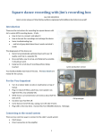
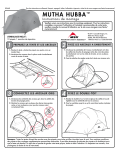
The Mutha Goose and Her Gaggle
Instruction Manual
Base Units
Overview
Wiring and Operation
DIP Switch Settings Defined
Buttons
Setup & Notes
DIP Switch Chart
Dailies Program Info
OPTIONAL : Mutha Hub
OPTIONAL : PIN Setter
OPTIONAL : Programming Custom Info via Terminal
2
3
3
5
6
7
9
10
11
12
Slave Units
Wiring and Operation
DIP Switch Settings Defined
Buttons
Fledgling Overview
Fledgling DIP Switch Chart
Gosling DIP Switch Chart
13
14
15
16
17
19
Common Printer Settings
Citizen 3541
Citizen 3551
21
22
Reliability Tips
23
Misc Game Setup Information
“Pot-O-Gold”
“Cherry Master”
“Omega/RamStar”
“QuarterMaster”
25
26
27
28
Warranty and Disclaimer
30
Mutha Goose & Gaggle
Instruction Sheet
V1.58/V1.60
Please Read ALL instructions before beginning an installation
Overview:
The “Mutha Goose & Gaggle” is a multidrop network system that allows up to 63 game
machines to be connected to a single master print station. It also has many features built
in that makes it ideal for use in the Coin-Op industry.Up to 63 (99 W/V1.60) machines can use
a single master printer station.
Features:
Up to 63 (99 W/V1.60) machines can use a single master printer station.
Sequential mode allows the automatic switching to a backup printer.
Fully stored bookkeeping and daily/shift books.
Reprint of last 10 or 25 monetary transactions.
Cabling is readily available “Category 5" network wiring.
Custom location header.
Single cable “Daisy Chain” to all machines.
One machine down does NOT affect other games.
Industry proven RS-485 protocol for maximum reliability.
Brown Out and Watch Dog protection.
Easy to bypass for normal “manual” collect.
Tampering with wires can not produce illegitimate vouchers.
Connections:
Base / Master Unit :
All of the connections are on the back panel and are marked on the case
for ease of use.
Power
:
+9VDC 1000mA wall transformer
2.1mm plus tip positive.
Network
:
RJ-45 plug that leads to the first game
in the network.
Printer A
:
Primary printer RS-232 connection.
Printer B
:
Optional backup printer, and all of the
programmable settings are set from here.
2
Base unit wiring & Operation :
The base unit is very straight forward. The wall transformer goes into the power jack.
Connect the proper length Cat5 cable to the network connector, this goes from the base
unit to the first game in the system. Printer A is where the primary printer is attached,
and Printer B is where the backup printer goes if you are using the system in
“SEQUENTIAL” mode. Printer B is also the port that is used to program the custom
settings.
Base unit operation is also very simple, but there are a few things to keep in mind. All
settings that are location specific are set inside the base unit. Such as the location header,
the date/time, how many units are in the system, and other voucher settings that are
consistent through out the location. Most settings are done through the three banks of
DIP switches that are inside the unit. Refer to the DIP switch chart while reading the
following settings.
Base Unit DIP switch setting explanation:
(See the DIP switch Chart)
Description
Possible settings
Maximum number
8 - 63
of machines in network
Operation Mode
Single Printer
Sequential
Diagnostics
Explanation
This setting is set to the lowest
number that is equal or greater
than the number of machines in
the network.
Printer Port A is the sole output
Port A and B are both used,
if one printer goes down the
other takes over.
Printer Port A is the sole output,
and all network messages are
printed out. Useful when first
setting up a location.
Check For CIAO Baby
YES/NO
Should the base unit attempt to
communicate with a credit box
History Summary
10 or 25
How many of the stored values
should be printed out when a
summary is requested. (V1.60 or
better)
Send CIAO Baby Credits
to PIN Setter
YES/NO
Should Credits sent by the CIAO
Baby be used to print phone/internet
PINs from a PIN Setter Module.
(V1.55 or better)
Send Money In Credits
to PIN Setter
YES/NO
Should money into the games be
used to print phone/internet PINs
from a PIN Setter Module. (V1.55 or
better)
3
Printer Type
Generic
Citizen/Epson
Star Micronics
Ithaca 70 series
Generic ASCII printer
Use the special features of these
printers.
Use Star control codes
Use Ithaca control codes
Use Date & Time
Yes/No
Should the date and time be printed.
12 or 24 HR Clock
12/24
Time be in 12 or 24hr format
Auto Adjust for DLS
Yes/No
Should the unit auto adjust for
U.S. Daylight Savings Time
Use Custom Header
Yes/No
If a location specific header has been
programmed, should it be used.
Multi-voucher Mode
Yes/No
Also called the ticket mode, if set
to yes the unit will print one voucher
for every trip point reached. Not
recommended for low value trip
points.
What Should the Voucher
be printed in.
Money
Print in dollars/cents.
Points
Print the amount in points.
Credits
Print the amount in credits.
Tickets
Print the amount as tickets.
SPECIAL NOTE : If you set the printout in Tickets and the Money Value to cents,
the unit will go into the “NOTHING” mode. The value of the
Ticket will not have any value before or after it, just a plain
number. (V1.60 or better)
If money dollars
or cents
Dollars
Cents
The value is in whole dollars.
The value has fractional dollars.
Customer Signature area
Yes/No
Print an area for the customer to
sign when redeeming the voucher.
Locality Specific Information
These settings are constantly in flux, but there
will always be a NONE ,USER, and CUSTOM
setting. NONE means just that, USER is to
print information that is entered by the operator,
and the CUSTOM setting is reserved by us. Any
other settings on your paperwork are to print the
data in such a manner to be more acceptable in
that area.
4
Base Unit External and internal buttons :
The standard base unit comes with 2 external buttons, an LED, a key switch, and a
buzzer. The key switch is to disable the book keeping button which also disables the clear book
keeping function. This is to keep a curious location employee from checking to see how much
money is in a particular machine, or clearing out the book keeping to cover missing money. The
Reprint/Summary button causes the base unit to issue a reprint of the last 5 voucher events
including the current date and time and the original vouchers’ date and time if that feature is
turned on. The book keeping button causes the base unit to print the total amount of vouchers
printed and then polls every game to collect the individual numbers. After this is done pressing
both buttons (reprint and books) will cause the base unit to reset its’ books and instruct all active
slave units to do the same. For normal operation the key switch should be in the off position.
The LED will light and a buzzer will sound if the system suffers from a printer error that needs
human intervention. When the base is in this state it will instruct all of the games on the network
to go into standby mode, which can lockout any collects and/or disable the DBA, resolving the
printer error (usually an out of paper condition) will cause all of games to come back online and
any pending events will get handled. Inside the base unit there are 4 more push buttons located
on the front edge of the PCB. These can be accessed by removing the 4 panel screws and lifting
the top panel off. This is also how you access the DIP switch banks. These buttons have
different functions depending on the mode of operation the base unit is in. When setting up a
location the base unit should be placed in the DIAGNOSTIC mode until the system has been
tested and verified. The internal buttons will help with this.
The following button functions are valid only when the unit is in DIAGNOSTIC mode.
Button 1
:
Base unit prints a summary of its’ current settings.
Button 2
:
Poll all possible node / slave addresses (1 - 63) for current settings
even if the base unit is set to poll less that 63. This is useful
to check out how each unit is set and make sure there are no
units set to the wrong node number.
Button 3
:
The base unit will send out the request for all units to coin up
100 credit units times the credit per dollar multiplier on the
slave unit.
Button 4
:
Pulses the remote collect line.
The Following button functions are for all other modes :
Button 1
:
Base unit prints a summary of its’ current settings.
Button 2
:
Base unit prints entire location book keeping.
Button 3
:
Base unit goes into setup mode for entering date/time/header
information. See setup mode below.
Button 4
:
Unused.
Button Combinations
Buttons 1 & 2 :
Clears Base unit books.
Buttons 1 & 3 :
Clears slave unit books.
Buttons 1 & 4 :
Clears entire base unit memory. Use if RAM error occurs.
5
Setup Mode:
When the unit is in a normal operation mode (any mode but DIAGNOSTICS) pressing
the internal button 3 will put the system in setup mode. You use setup mode to set the date and
time, enter a custom header message, or add locality specific information to the voucher. You
use a PC or laptop PC with a 9 pin female to 9 pin female straight through cable, and terminal
software. “Windows” based PCs can use the HYPERTERM software that comes bundled with
Windows. To make the connection, connect the cable between PORT B on the base unit and a
serial port on the PC. Set your terminal software to 8 data bits, one stop bit, no parity, no flow
control. Then press button 3. You will get a menu of choices and instructions from the base
unit. If at any time you get lost, or things don’t seem to be functioning press the reset button to
allow the system to go back to normal operation. It is best that the network not be in use while
making any changes. See the attached sheets for more detailed information on using your PC to
setup your base unit. The unit must have either a printer or a printer bypass plug (available on
request) connected to PORTA for the unit to go into setup mode from a power up state, or you
can plug the PC into PORTA and then move it to PORTB after the power up message.
Misc. Base Unit Notes :
We recommend the Citizen IDP-3551 serial printer for its’ reliability, ease of use, price,
and the ability to print in two colors. When set to the CITIZEN setting the base unit takes full
advantage of the Citizen printers’ ability to print in both red and double sized characters to make
all vouchers and reports as easy to read as possible, and as hard to falsely duplicate as possible.
While all of the other manufacturers make a fine product, and we make use of any special
features they have to offer, we have found the IDP-3551 to be the optimal choice. In any case,
when choosing a printer it should offer the following communication protocol for proper
operation : 9600baud, 8 data bits, one stop bit, and DTR/DSR flow control. Also, the printer
should provide a battery backed buffer, so any unprinted characters are not lost during a power
failure. Other settings will be based on how the unit is being operated. In the single printer
mode, we do not recommend that the unit be fully unsupervised, and the printer should offer a
buffer of at least 2000 characters. In the sequential mode we recommend that the buffer be set to
200 - 300 characters if possible. This allows the backup printer to take up where the other left
off without having any vouchers caught in limbo. If the network has more than 20 machines the
system should not be run as an unsupervised location, and the printers should be set to the
highest buffer value, 2000 characters or above, to maximize system throughput. In this situation
any vouchers stored in the printer buffer will be printed when the paper is reloaded. These
settings should be followed even if the system is set up with a backup printer and the unit is
being run in sequential mode. We have included sheets on the recommended DIP switch settings
for the Citizen printer in the following DIP switch sheets.
6
Mutha Goose V1.60NDL
DIP Switch Bank 1
Description
Maximum
Number of
Machines
in
Network
Value
1
2
3
4
5
6
10 ( 8*)
0
0
25 (16*)
1
0
50 (32*)
0
1
99 (63*)
1
1
Single Printer
0
0
Sequential
1
0
NOT USED
0
1
Diagnostics
1
1
Generic
0
0
Citizen/Epson
1
0
Star Micronics
0
1
Ithaca 70
1
1
7
8
Operation
Mode
Printer
Type
Number of transactions to print with
summary button
25
0
10
Use CIAO Baby
Credit Unit
1
No
0
Yes
1
* Values for earlier Firmware. V1.60 and above will do up to 99 machines
Mutha Goose V1.60NDL
DIP Switch Bank 2
Description
Value
1
Use
Date and Time
12 or 24
Hour clock
Automatically
Adjust for
Daylight Savings
Use Custom
Header Message
Multi-Voucher Mode
(Ticket Mode)
NO
0
YES
1
12
0
24
1
3
NO
0
YES
1
4
NO
0
YES
1
5
NO
0
YES
1
Not Used
N/U
Send CIAO Baby Credits to PIN Setter
NO
YES
Send Money In to Machines to PIN Setter
2
6
7
8
0
0
1
NO
0
YES
1
7
Mutha Goose V1.60NDL
DIP Switch Bank 3
Description
Value
What should
the voucher
value be
printed in
1
2
MONEY
0
0
POINTS
1
0
CREDITS
0
1
TICKETS*
1
1
3
4
5
6
7
NONE
0
0
0
AR
1
0
0
GA
0
1
0
KY
1
1
0
TN
0
0
1
TX
1
0
1
CUSTOM
0
1
1
USER
1
1
1
If in money
dollars or cents
DOLLARS
0
CENTS*
1
Customer Signature
Area
NO
0
YES
1
Include
State or locality
Specific
Information
Print Extended Plays
Collected Info
8
No
0
Yes
1
*On V1.60 or Better, setting to TICKETS and CENTS causes the Mutha Goose to print no
defining value before or after the number. For example, instead of saying “$10.00" or “10
TICKETS” the unit would just print “10”.
8
Mutha Goose
Dailies Program Information
Overview:
The dailies program just creates a separate set of running books that can be printed and
cleared separately from each other. This allows the location to access one set of books for in
house use and the main books can be protected by the key and only accessed during a collection.
Naturally, there are other scenarios that another set of books may come in handy for.
Setup Information :
You should be using Gaggle V1.26 or better, Fledgling V1.26 or better and the base unit
should have V1.58 or better installed. These ICs are available from RKS if you need to upgrade
any of your units. Be aware that the memory of the units will be cleared when upgrading to the
dailies programs, so you should do a full bookeeping dump before the upgrade. The best time is
during a location collection after all the bookeeping and money have been settled and verified.
If the base unit is being upgraded you will need to add a push button switch for the dailies. We
recommend a button similar to the existing switches, which are available at Radio Shack, and
that the dailies button be placed 2 inches below the Summary Reprint button. (See Photo)
The Daily button should get its’ ground from the Summary Reprint button and the other
connection should go to pin 3 (counting left to right) of the 6 pin panel connector. (See Photo)
This will allow the dailies to be printed and cleared without the need for a key, while keeping the
main books protected.
Change all the ICs at once and power up the games first. Make sure that they all power up
with flashing status LEDs. Once those have been verified, power up the base unit. It should
power up and print a power up ticket. You may be asked to press buttons 1 and 4 inside the base
unit to clear the RAM, do so if requested.
9
Mutha Hub
Overview :
The Mutha Hub is an RS-485 network hub that is compatible with both our Mutha Goose
and the Remote Credit systems. It allows you to do things with the network that would
otherwise require extra cabling. Things like network stubs or modified star topologies are
no longer impossible. It is useful for dropping a line over into an “island” of games
without requiring the daisy chain to return (a stub), or to run games in areas on opposite
ends of the building without having to make a giant loop to maintain the daisy chain.
Along with creating two independent outputs, the unit also offers 1500V of isolation
between the primary network and both outputs. This means that a catastrophic failure on
a game on one of the isolated stubs can not affect the other sections of the network.
Operation :
The Hub is pretty straight forward to use. The primary network is that going back to the
Mutha base unit. It is the input to the Hub. If the hub is the last item on the net the Last
Node jumper should be installed. The primary network out jack can be used to either
continue on to other games or be used to stack multiple hubs. For the most robust setup,
if the unit is just being used to drop a line to an island
10
PIN Setter
Instructions
The PIN Setter prototype is easy to set up. Take the 3' CAT5 cable and
use it to put the unit inline with the base unit, connect the printer to the PIN
Setter using the DB-9 to DB-25 printer cable, and plug in the power
transformer. That’ all there is to it. Inside the Mutha unit you must set the
switches for proper operation. If you are using a CIAO Baby (Credit Unit)
and you want it to print PINs on remote credits turn Bank 2 Number 7 ON
and if you want it to print PINs on money into the game’s DBA turn Bank 2
number 8 ON.
The PIN IC’s are located inside the unit in a ZIF socket that uses a small
screwdriver to turn the release. They are marked H and L and are compatible
with our F1_Pin boards.
PIN Setter V1.00
Description
Printer
Value
1
2
3
GENERIC
0
0
0
Citizen/Epson
1
0
0
Ithaca 70
0
1
0
Star
1
1
0
ESC/POS
0
0
1
TG-558
1
0
1
N/U
0
1
1
N/U
1
1
1
Type
Loop
PINs
Jumper Settings :
JMP1
JMP2
4
NO
0
YES
1
OFF = $1 PINs
ON = $5 PINs
NOT USED
11
Programming Custom Features
The Mutha Goose has several functions and features that can only be set in a special mode
using a terminal program, on a PC or Laptop, and a serial port.
The functions that require setup through the serial port are Date and Time, Location
name/Header, and Custom Text before and after the collect amount.
We recommend HyperTerminal for your terminal program because it is included free with
many versions of Microsoft Windows.
You will find it under START/All Programs/Accessories/Communications/HyperTerminal
If you do not find it there it may not have been installed on your system. A quick Web Search for
HyperTerminal Personal Edition will get you to the proper website, but any terminal program
should work fine.
You will also need a 9 pin serial port available on your computer system, if you are lacking
this port, a USB to Serial dongle will be required also. You can get these at most Big Box
electronic stores or through us, and you will need the DB-9 to DB-9 programming cable that we
include with the base unit.
The COM port setup parameters are :
9600 Baud
8 Data Bits
1 Stop Bit
No Parity
Terminal Emulation should be None or TTY.
To connect to the Mutha Goos you should have either a printer or a printer fooler/bypass unit
plugged into PORT A on the back of the Mutha and the programming cable plugged into PORT
B.
Once you have your terminal program configured all you need to do is power up the Mutha
and press Button 3 inside the fron of the unit. You will need to remove the cover to get to the
button. At that point, if all is well, you will see a menu on your computer screen and everything
is explained on screen from there on out.
The most common problem encountered when setting all this up is not knowing which COM
port your terminal program should connect to and plugging into the wrong port on the back of the
Mutha. If you are using a USB dongle, the first time you plug it in your system should report
what COM port the unit is configured for, write it down for future reference. If you have
forgotten which port it is, you can just try each available port until the connection is made. There
shouldn’t be that many options to choose from.
12
Slave Unit Wiring and operation :
All connectors have a square solder pad denoting Pin 1 and the connector
designator text (J1, J2, J3) is nearest pin 1.
Connector
J1
J1
J1
J1
J1
J1
Pin
1
2
3
4
5
6
Description
Credit Pulse In
Coin In for book keeping
Bypass Switch +
Bypass Switch Tamper Switch +(Or Lockout)
Tamper Switch -
Wire Color
Orange
Grey
Red
Black
White
Black
J2
J2
1 & 2 Power GROUND
3 & 4 Power +5VDC
Black
Red
J3
J3
J3
J3
J3
J3
J3
J3
1
2
3
4
5
6
7
8
Blue
Credit Return/Out
+5VDC out (not used)
Remote Collect (not used)
+5VDC out (not used)
Error Lamp Error Lamp + for 5VDC lamp
System Enable/ Switch GND
+5VDC out (not used)
Yellow
Violet
Green
How to wire your cabinet to the slave unit :
J1
The ORANGE wire (Pin 1) should go to your source of pulses when the unit is
collected. In a “Cherry Master” Style game this is Pin 28 parts side on the edge
connector, or the signal that is commonly referred to as “KEY DOWN COUNTER”.
The GREY wire (Pin 2) is connected to the “In Meter” line and is used solely for
book keeping and reporting. There is a setting to divide this count before reporting
so you can keep all your meters equal even if the games are not. For example, if your
games’ out meter is in nickels, but you want it to report in dollars set the coin in
divisor to 20.
The RED wire (Pin 3) and its’ ground (Pin 4) are for a bypass switch. If for some
reason the network were to go down the slave unit is normally wired to disable the
collect button and the DBA, to manually re-enable these functions a switch
(We recommend a key switch) can be connected here. A system of hand written
vouchers can then be employed until the error is corrected.
The WHITE wire (Pin 5) and its’ GROUND (Pin 6) are to be used with an alarm
style normally open (N/O) reed switch. If the game is opened the base unit will sound
an alarm and print out a voucher showing which machine is the one being tampered with.
J2
The power cable should go directly to the power supply, do not use the PCB edge
connector for a tie point. The BLACK and GREEN wires go to DC GROUND and the
RED and WHITE wires go to +5VDC.
13
J3
The BLUE wire (Pin 1) is used when returning any unused credits back to the machine.
To take advantage of this feature, the machine should have a credit or service input that
can be set on a 1 to 1 ratio and the unused credit return option should be turned on.
The YELLOW wire (Pin 3) is currently unused.
The Violet wire (Pin 5) can be used to light an error lamp on a machine to let the
location know the machine is not currently on the network, or is malfunctioning.
The GREEN wire (Pin 7) is the system enable line. For the utmost in security and
reliability this wire should be properly used. The normal ground should be removed
from the COLLECT switch and this line be put in its’ place. This will keep a player
from trying to collect a machine when the network is down for one reason or another.
It should also be connected to the ENABLE- pin on the DBA (see your DBA
documentation for the specifics) so money can not be placed in a machine that is
not currently online.
LAST NODE JUMPER
The board also includes a pair of jumper pins labeled LAST NODE, this should be
shorted if the machine is the last in the string. In other words the “NETWORK IN” plug
is used but the “NETWORK OUT” plug is empty. The machine number itself is not
important, just whether it is the last in the string or not.
THERE SHOULD ONLY BE *ONE* LAST NODE JUMPER ON A STRING OF
MACHINES!
Slave Unit DIP switch setting explanation:
(See the DIP switch Chart)
Description
Possible settings
Pulses in
1 through 5000
to equal
(Some may have
one internal
custom settings)
point
Explanation
This is the number of pulses the game
has to put out to get something.
For example 100 nickels to get an
internal point.
Each point
is worth
1 through 1000
What is the above point worth.
In keeping with the above example,
100 nickels would be worth 5 items.
The base unit will then use its’ settings to
determine if that should be dollars, points,
tickets, or whatever.
Unused Credit
Return
ON/OFF
Should any “odd” credits be returned
To the game.
Credit Speed
FAST/SLOW
Some games require a slower coin
Pulse than others.
Coin In
Divisor
1 through 100
This setting allows you to use the system
to keep track of all of your machines
in the same denomination. That way
If you have penny, nickel, and quarter
games all in the same location, you
can keep track of all of them in dollars.
This is simply for book keeping
simplicity.
14
Remote out
1 through 100
How many pulses should the
Fledgling/Gosling put out for each dollar
from the CIAO Baby.
Node Number
1 through 63
Each slave has to have a unique number so
the master can identify and communicate
with it. When a voucher is printed the
node or machine number is printed at the
top. You add up the switch values to get
the node setting.
Slave Unit Buttons :
The slave unit has two function buttons that can be used to print and/or clear the book
keeping and the setup of the individual machine. The functions just duplicate what can be done
globally from the master, but on a machine by machine basis.
BUTTON 1 :
Print the Books for the specific machine.
BUTTON 2 :
Print the status/setup of the specific machine
COMBO of 1 & 2
:
Clears the memory of the specific slave unit.
Misc. slave notes :
The node number is also the “Machine Number” on the printed voucher. All of the slave unit
inputs are diode blocked and optically isolated, so the inputs are protected from a continuous
75V source, and a 2500V spike. This means the inputs can coexist with PROPERLY wired hard
meters if you need to double check the validity of any book keeping numbers. The status LEDs
on the unit should give you a basic idea if anything is going awry. The red LED is on when the
unit is on and executing instructions. The yellow LED is on when the unit is sending data out
onto the network. The green LED is on when there is incoming network traffic. In a normal
situation the red LED should be on, the yellow should flash about once a second, and the green
should flicker all the time. Also, the in and out cables should have some type of strain relief
attached to them where they enter and exit the cabinet. A cable tie with an integral screw hole is
perfect. That way a player or route person pulling on the cabinet does not break the network
connector on the slave board.
See the attached sheets on safety an reliability for additional information.
15
Fledgling
Replacement for the Gaggle
Overview :
The Fledgling PCB is a direct, pin for pin compatible, replacement for the Gaggle PCB. It incorporates
some technology improvements along with some enhancements to ease installation and operation.
Enhancements and changes :
The Fledgling can operate from 4.5 to over 5.25VDC with no compromise is reliability. It now uses direct
setting rotary switches to set the machine number, so no more adding up the values on DIPSW3, just set 01 to
63 on the dials and off you go. All of the printout value options are now on DIPSW1 which is a 10 position
unit, no more spill over onto DIPSW2. The battery backed RAM has been replaced with a nonvolatile FRAM,
so there is no battery to go dead down the road. The firmware supports the latest Mutha operating modes, such
as daily books along with the standard book keeping data, and all the stored data is stored redundantly, so if one
copy gets corrupted the back up copy is used to restore from.
What this all means is a better product to you at the same price point.
PCB Layout :
16
Fledgling V1.XX
Description
Value
DIP Switch 1
1
2
3
4
5
1
0
0
0
0
0
2
1
0
0
0
0
Pulses in to
equal one
internal point
4
0
1
0
0
0
5
1
1
0
0
0
(Pulses in to get a voucher)
8
0
0
1
0
0
10
1
0
1
0
0
15
0
1
1
0
0
20
1
1
1
0
0
25
0
0
0
1
0
40
1
0
0
1
0
50
0
1
0
1
0
75
1
1
0
1
0
100
0
0
1
1
0
150
1
0
1
1
0
200
0
1
1
1
0
250
1
1
1
1
0
400
0
0
0
0
1
500
1
0
0
0
1
1000
0
1
0
0
1
2000
1
1
0
0
1
2500
0
0
1
0
1
5000
1
0
1
0
1
0
1
1
0
1
1
1
1
0
1
Internal point
is multiplied
by :
(What the above number is worth)
For example,
If the machine is a nickel out and
you want to collect in $5.00
increments,
you would set the internal point
value to 100 and the multiplier
to 5.
100 nickels = $5.00
6
7
8
9
1
0
0
0
0
2
1
0
0
0
5
0
1
0
0
10
1
1
0
0
15
0
0
1
0
20
1
0
1
0
25
0
1
1
0
50
1
1
1
0
75
0
0
0
1
100
1
0
0
1
150
0
1
0
1
200
1
1
0
1
250
0
0
1
1
400
1
0
1
1
500
0
1
1
1
1000
1
1
1
1
10
17
Fledgling V1.XX
DIP Switch 2
Description
Value
Unused Credit
Return
OFF
0
ON
1
Credit Speed
(unused/remote)
FAST
0
SLOW
1
Coin In
Divisor
For
Bookkeeping
Remote
Out
Pulses
per
Dollar
1
2
3
4
5
6
7
8
1
0
0
0
4
1
0
0
10
0
1
0
20
1
1
0
100
0
0
1
1
0
1
1
0
0
4
1
0
20
0
1
100
1
1
DIP Switch 3 has been replaced with direct reading rotary switches
Node
Number
Set by BCD/Numerical Switch
01 - 63 valid range
18
Gosling V1.00
Description
Pulses
In
to
Equal
one
internal
Point
Each
Internal
Point
is
worth
(Multiplied by)
Value
DIP Switch 1
1
2
3
4
5
1
0
0
0
0
0
2
1
0
0
0
0
4
0
1
0
0
0
5
1
1
0
0
0
8
0
0
1
0
0
10
1
0
1
0
0
15
0
1
1
0
0
20
1
1
1
0
0
25
0
0
0
1
0
40
1
0
0
1
0
50
0
1
0
1
0
75
1
1
0
1
0
100
0
0
1
1
0
150
1
0
1
1
0
200
0
1
1
1
0
250
1
1
1
1
0
400
0
0
0
0
1
500
1
0
0
0
1
1000
0
1
0
0
1
2000
1
1
0
0
1
2500
0
0
1
0
1
5000
1
0
1
0
1
0
1
1
0
1
1
1
1
0
1
DIP Switch 2
6
7
8
1
2
3
4
5
6
7
8
See
Next
Sheet
1
0
0
0
0
2
1
0
0
0
5
0
1
0
0
10
1
1
0
0
15
0
0
1
0
20
1
0
1
0
25
0
1
1
0
50
1
1
1
0
75
0
0
0
1
100
1
0
0
1
150
0
1
0
1
200
1
1
0
1
250
0
0
1
1
400
1
0
1
1
500
0
1
1
1
1000
1
1
1
1
19
Gosling V1.20
DIP Switch 2
Description
Value
Unused Credit
Return
OFF
0
ON
1
Credit Speed
(unused/remote)
FAST
0
SLOW
1
Coin In
Divisor
For
Bookkeeping
Remote
Out
Pulses
per
Dollar
4
5
6
1
0
0
0
4
1
0
0
10
0
1
0
20
1
1
0
100
0
0
1
1
0
1
3
7
8
2
3
4
5
6
7
8
U
s
e
d
0
4
1
0
20
0
1
100
1
1
4
1
N
o
t
0
2
Add Values
for
1 - 63
2
1
1
Node
Number
1
DIP Switch 3
1
1
1
8
16
32
1
1
1
For example Node 11 would be switches 1,2,4 on the rest off.
(1 + 2 + 8 == 11)
J1 Pin 5
Tamper SW or
Coin Lockout
Tamper
0
Lockout
1
20
21
22
Mutha Goose and Gaggle Reliability Tips
or, How to Make Your Network Live Through a Thunderstorm
You can commit a lot of sins putting a game together, and get away with it, when the game is going to be
operated as a stand-alone machine, but when you start running wires between them you have to pay careful
attention to things you may not have even known about in the past. This guide is designed to give you a check
list of items you should go through every time you build a machine, add a machine to an existing network, or
service a location that has suffered damage from lightening. We are going to break this down into four parts,
what tools and materials you should have on hand, what you should do with your base unit (Mutha), how the
individual machines should be wired, and what to look for at the location.
Tools and Materials:
The following should always be with you, no exceptions.
1) An electronic digital multi-meter
Even the cheap $15.00 units are better than an analog meter. The big advantage is the reading
on the LCD isn’t subject to misreading.
2) A wall outlet tester
Just because the wall outlet has a 3-prong plug, there is no guarantee that the 3rd prong is hooked
to anything. The Earth ground is where ALL stray currents should be shunted to, not the network
board or your game board.
3) A CAT5, or better, network cable tester
You can’t tell if that wire in the ceiling or through that wall is any good if you don’t have one.
The best one to have, and it is reasonably priced, is made by Punktal, Part Number TCT-141.
It has a remote terminator that you can put on the far end of the cable so you don’t need to have
access to both ends of the cable to test it. It will spot miswires, opens, and shorts.
4) A selection of .093 pins and a real crimp tool
The best way to make a good power supply connection is in the output plug on the power supply
and you will need some male pins to do that.
5) Some butt connectors and an insulated connector crimp tool
I know we aren’t suppose to strip wires, twist them, and then tape them off, but we do it anyway,
and that piece of tape that was really sticky 4-5 years ago has since fallen off and we now have a
bunch of bare (and loose) connections in the machines. It is really easy to just slip one end of a
butt connector over the twisted wires and give them a crimp.
6) Your manuals for the machines and the Mutha Goose
We print these things by the hundreds and give them out with every system. There is no reason
for every service person and/or location to not have a manual. We will gladly supply a few
extras in an order if you just ask.
The Base (Mutha) Unit :
The base unit is pretty straight forward and not a lot can go wrong with it, but there are a few things that can
be done to improve performance and reliability.
1) Make sure the wall outlet is properly grounded/wired using your wall outlet tester
2) Use a surge protector and plug the base unit’s power supply and the printer(s) into it
For the ultimate in protection and reliability, you can buy a small 600VA UPS/backup power
supply and use it in place of the surge protector. Do NOT use both. A surge protector on the
UPS’s input can alter how it protects the network, and one on the output can actually damage the
UPS.
3) Make sure you have the latest firmware in the unit
You can get the revision number by cycling the power. We only charge for the cost of the blank
IC, and it keeps the system up to the latest compliance regulations.
23
The Game Machines :
This is the most critical link in the chain. I have seen a steady decline in the quality of the interior wiring of
the cabinets over the last 10 years, and some of the short cuts that are being done are down right dangerous.
1) Power Cords
EVERY power cord should have the 3rd prong intact.
2) Ground Continuity
That ground should test for continuity from the lug on the power cord to the case of the power
supply, the frame of the monitor, and it should be connected to EVERY metal surface that a
player can come into contact with, PERIOD. Anything less is dangerous and leaves your game
susceptible to electrical noise.
3) Ground bonding
On the old CRT monitors the Earth ground and the DC ground got coupled together via the
RGB/SYNC connection. With the advent of LCD monitors, this is no longer the case. So, your
DC ground is fairly isolated and I can’t vouch for how well the current power supplies are
handling excessive noise, voltage, or currents on the DC ground in respect to the AC ground. I
would suggest that a 10 - 100 Ohm resistor be placed from the DC ground to the Earth ground as
close to the power supply as possible. You can even bond one of the DC ground wires to a screw
on the power supply case if it is grounded.
4) All CRT (non-LCD) monitors must have isolation
If your CRT monitor didn’t have an Earth ground running to it, it might have been because whom
ever made the game took the ultimate short cut. They left out the isolation transformer and just
made sure there were no Earth grounds running to anything in the cabinet. This is an extremely
dangerous situation and must be tested for and corrected before anything else. If you have a
game with a CRT monitor in it, it is cheap insurance to just add an isolation transformer if you
don’t see one in the machine. You can test for it by checking for continuity from the line cord
prongs to the monitor AC input. There should be no continuity between them. The nice thing is,
if you run a ground to the chassis and there is an isolation problem, it will just blow the fuse on
the monitor instead of frying all the network boards.
5) Power Supply Voltage
The Gaggle PCB should be run from 4.90 - 5.10VDC w/ < 100mV of ripple.
If you have a board set that needs to run higher than 5.10, we have small switcher supplies that
will let you run the Gaggle PCB from the +12VDC lines by regulating it down to 5VDC.
The Fledgling board is a lot more liberal in its’ power demands. It will work from 4.5 - 5.5VDC
with no problems. If you have a machine acting funny, the power is the first thing you should
test.
6) Strain Reliefs
The CAT5 network cables should be long enough that they don’t get tugged when you jockey a
machine around to move it or work on it. Every set of cables should have a hold down strain
relief so if the wires do get pulled they are not breaking off the network jacks.
The Location :
The location wiring is as much a part of the network wiring as the CAT5 cable is.
1) Wall Sockets
Every wall socket should be tested with your wall outlet tester. If there is an open ground in the
wall outlet, the only place for stray voltages/currents to go is down the network wire.
2) Vermin control
Rodents LOVE to chew on network wires. I have seen wires on floors, in ceilings, and inside of
walls that have been chewed completely through by mice. Test your cables if they are hidden, or
out of the way, and you are having network resets or data errors.
3) The machines should not share a circuit with any big current or noisy loads.
If the machines are sharing a power circuit with refrigeration equipment, fluorescent lighting, or
some other big load, you can have issues. Remember these aren’t just games, they are computer
systems.
24
Pot-O-Gold Machine
Pin Out (Your Harness colors *MAY* be different)
BLK
GROUND
A
1
GROUND
BLK
BLK
GROUND
B
2
GROUND
BLK
RED
+5VDC
C
3
+5VDC
RED
+5VDC
D
4
+5VDC
-12VDC
E
5
-12VDC
BLU
+12VDC
F
6
+12VDC
WHT
KEY
H
7
KEY
GRY/BRN
METER “B”
J
8
METER “A”
GRY/BLK
YEL/BLK
BILL LOCKOUT
K
9
COIN LOCKOUT
PNK/BLK
N/U
L
10
SPEAKER OUT
YEL
YEL/RED
RXD FROM DBA
M
11
HOPPER DRIVE
BRN/WHT
GRN/WHT
VIDEO GREEN
N
12
VIDEO RED
RED/WHT
GRY/WHT
VIDEO SYNC
P
13
VIDEO BLUE
BLU/WHT
WHT/BLK
SUPERVISOR KEY
R
14
VIDEO GROUND
BLK
GRY/YEL
METER “D”
S
15
METER “C”
GRY/ORN
CASH DOOR SW
T
16
COIN SW
WHT/PNK
MAIN DOOR SW
U
17
DBA INT LINE
WHT/YEL
LOGIC DOOR SW
V
18
ATTENDANT KEY
WHT/ORN
N/U
W
19
N/U
WHT/RED
HOPPER FULL SW
X
20
N/U
WHT/ORN
HOPPER LOW SW
Y
21
COLLECT SW
WHT/YEL
HOPPER COIN SW
Z
22
N/U
WHT/GRN
CALL ATTEND SW
a
23
PLAY SW
BRN/BLK
DIVERTER COIL
b
24
N/U
ORN/BLK
DBA SEND LINE
c
25
BELL
VIO/BLK
ORN/BLK
METER “E”
d
26
COLLECT LAMP
BRN/WHT
YEL/BLK
METER “F”
e
27
METER “G”
BLK/WHT
GRN/BLK
CALL ATTEND LAMP f 28
PLAY LAMP
Use COIN LOCKOUT when using COIN SW to avoid lockout errors.
COIN LOCKOUT to J1 Pin 5 and COIN SW to J3 Pin 1
GRY/BLK
WHT
WHT/RED
WHT/BRN
WHT/GRY
25
Cherry Master
Edge Connector ( 72 Pin )
Parts Side
Solder Side
Video RED
1
Video GREEN
Video BLUE
2
Video /COMP SYNC
3
4
5
6
7
Service Switch
8
Start Switch
9
Small / Center Stop Switch
10
Play Points Switch
11
Take Score / All Stop Switch
12
Double-Up / Left Stop Switch
13
14
15
Big / Right Stop Switch
16
17
Coin A Input
18
Key In Switch
Coin C Input
19
Coin D Input
20
Status Screen Switch
Hopper Collect Switch
21
Collect Points Switch
Hopper Full Switch
22
Hopper Switch
Coin A Counter
23
Key In Counter
24
Coin C Counter
25
Coin D Counter
26
Hopper Counter
27
Collect Point Meter
28
Start Lamp
29
Cancle Lamp
30
Play Point Lamp
31
Take Score Lamp
32
Double Up Lamp
33
34
35
GROUND
36
GROUND
Edge Connector ( 20 Pin )
Parts Side
Solder Side
GROUND
1
GROUND
GROUND
2
GROUND
+5VDC
3
+5VDC
+5VDC
4
+5VDC
+12VDC
+12VDC
5
Counter +V (not used)
6
Hopper AC Switch
7
Hopper AC Switch
8
GROUND
9
GROUND
GROUND
10
GROUND
26
“Omega”
Coin Meter Output
Tap off U59 Pin 2
27
Quarter Masters
3 Player Game to Mutha System
You will need 3 of the “Generic Isolator” PCB for a full installation. If you are not going to be
remote collecting, you can get away with 2.
You must have all 3 Fledgling/Slave boards running from the same power supply and that
power supply should not have a common ground to the game boards. A 5VDC wall
transformer capable of 500mA or more should be adequate and easy to install.
Before going any further, the Fledgling should all be installed and functioning. You can check
that by using the buttons on the Fledglings to get bookkeeping and status reports.
The following connections will need to be made for the cash out/collect of the Quarter Masters
board to work. On the Opto boards Pin 1 is the left pin as looking at the board edge on, and
there is a square pad on the bottom of the PCB for pin 1. On the Fledgling boards the same
thing applies, and the connector number (JX) is always next to Pin 1.
On the Opto board, cut off the 3 shorting jumpers near the Input connector and add 3 jumpers
to the side that says Outputs. Any small piece of wire will do.
Generic Isolator # 1
Input Connector
1
Game 1 Out meter +
2
Game 1 Out meter 3
Game 2 Out meter +
4
Game 2 Out meter 5
Game 3 Out meter +
6
Game 3 Out meter 7
N/U
8
N/U
Output Connector
1
Fledgling 1 J1 Pin 6
2
N/U
3
N/U
4
Fledgling 3 J1 Pin 1
5
N/U
6
Fledgling 2 J1 Pin 1
7
N/U
8
Fledgling 1 J1 Pin 1
On the Fledglings, turn all switches on DIP Switch 1 to off, and collect credits from each
station. You should get a print out from each unit. The amounts might not be correct, but they
should print the number of credits from each station.
28
Generic Isolator # 2
Input Connector
1
Fledgling 1 J3 Pin 2
2
Fledgling 1 J3 Pin 1
3
N/U
4
Fledgling 1 J3 Pin 3
5
N/U
6
Fledgling 2 J3 Pin 1
7
N/U
8
Fledgling 2 J3 Pin 3
Generic Isolator # 3
1
Fledgling 3 J3 Pin 2
2
Fledgling 3 J3 Pin 1
3
N/U
4
Fledgling 3 J3 Pin 3
5
N/U
6
N/U
7
N/U
8
N/U
Output Connector
1
Station 2 Collect Button 2
Station 2 Collect Button +
3
Station 2 Credit SW 4
Station 2 Credit SW 5
Station 1 Collect Button 6
Station 1 Collect Button +
7
Station 1 Credit SW 8
Station 1 Credit Sw +
1
2
3
4
5
6
7
8
N/U
N/U
N/U
N/U
Station 3 Collect Button Station 3 Collect Button +
Station 3 Credit SW Station 3 Credit Sw +
29
Warranty and Disclaimer Information
RKS, Inc. warranties the base and slave units for a period of 90 days
against defects in materials or workmanship. RKS, Inc. will, at its’
discretion, repair or replace any defective unit and pay for standard ground
shipping back to the purchaser. Damage caused by improper use or
installation shall be the sole responsibility of the purchaser. RKS, Inc. its’
officers, or employees will not be held responsible for any losses or injuries,
real or intangible, due to the use or misuse of this, or any other RKS, product.
The suitability of this product to perform any specific task is the purchaser’s
responsibility. If you decline agreement with the above disclaimer contact
RKS, Inc., before installation, for information on how to return the product.
RKS, Inc.
(800)360-1960
137 Bethea Rd. #701
Fayetteville, GA 30214
www.reallykillersystems.com
30