1
"
"( £
....•.......
~'
}'
4.\
o.
to·······. ·
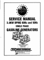
SERVICE MANUAL
3.0KW BPMG 60Hz and 50Hz
SINGLE PHASE
GASOLI
ENERATORS
rPiJBLiCt~ NO. 52089
I
SECOND EDITION
MARCH 2009
~
WESTERBEKE
WESTERBEKE CORPORATION' 150 JOHN HANCOCK ROAO
MYLES STANOISH INDUSTRIAL PARK' TAUNTON MA 02780
WEBSITE: www.WESTERBEKECOM
.
~
...
Membu Nlltional Mllrln~ Manufacturers Association
I
Gasoline with an ETHANOL content
higher than 10% (E10) is not allowed
and may void warranty.
Engines & Generators
A WARNING
Exhaust gasses contain t:arbon Monoxide, an odorless and
colotless gas. t:arbon Monoxide Is poisonous and can cause
u/lt:llllSCiDusness and death. Symptoms of Corbon Monoxide
exptJSII1fI can Include:
-Dizziness
-.."..
-'''stew
- WubIIss and Sleepiness
- Throbbing In Temples
- Muscular Twitching
- Vomiting
-Inability to Think Coherently
IF YOII DR All'f0NE ELSE EXPERIENCE ANY OF THESE SYMPTOMS,
BET DIIT INTO THE FRESH AIR IMMEDIATELY. If symptoms pelSlst,
. . . mtldical attBntion. Shut down the unit and do not restart
_I
Inspected and repaired.
\
!o!o!~
A WARNING DECAL Is plOvlded by
WESTERBEKE and should be fixed to a
bulkhtlBd near your engine Dr generator.
WESTERBEKE also recommtllllls Installing
CARBON MONOXIDE OETECTORS In the
Ilvlng/s/eeping quartelS of your vessel.
They are Inexpensive and easily
obtainable at your local marine store.
CALIFORNIA
PROPOSITION 65 WARNING
Marine diesel and gasoline engine
exhaust and some of Its constituents
are known to the State of California
to cause cancer, birth defects,
and other reproductive harm.
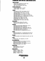
SAFETY INSTRUCTIONS
INTRODUCTION
PREVENT BURNS - FIRE
Read this safety 1TUlnual carefully. Most accidents are
caused by failure to follow fundamental rules and
precautions. Know when dangerous conditions exist and
toJre the necessary precautions to protect yourself, your
personne~ and your machinery.
The following safety instructions are in compliBnce wiJh
the American Boat and Yacht Council (ABYC) standards.
A WARNING: Fire can cause injury Of death!
•
Prevent flash fires. Do not smoke or permit flames or
sparks to occur near the carburetor, fuel line, filter, fuel
pump, or other potential sources of spilled fuel or fuel
vapors. Use a suitable container to catch all fuel when
removing the fuel line, carburetor, or fuel filters.
• Do not operate without a Coast Guard Approved flame
arrester. Backfire can cause severe injury or death.
• Do not operate with the air cleaner/silencer removed.
Backfire can cause severe injury or death.
• Do not smoke or permit flames or sparks to occur near
the fuel system. Keep the compartment and the
engine/generator clean and free of debris to minimize the
chances of fire. Wipe up all spilled fuel and engine oil.
• Be aware - diesel fuel will bum.
PREVENT ELECTRIC SHOCK
A WARNING: Do nat touch AC electrical connectiollS
willis BIlIlne Is running,
Of wilen connected to
shore
power. Lethal voltage Is p/TISBnt at these connections!
•
•
•
•
•
•
•
Do not operate this machinery without electrical
enclosures and covers in place.
Shut off electrical power before accessing electrical
equipment.
Use insulated mats whenever working on electrical
equipment.
Make sure your clothing and skin are dry, not damp
(particularly shoes) when handling electrical equipment.
Remove wristwatch and all jewelry when working on
electrical equipment.
Do not connect utility shore power to vessels AC
circuits, except through a ship-to-shore double throw
transfer switch. Damage to vessels AC generator may
result if this procedure is not followed.
Electrical shock results from handling a charged
capacitor. Discharge capacitor by shorting terminals
together.
PREVENT BURNS - EXPLOSION
A WARNING: ExplosiollS from fuel vapolS can cause
injury Of death!
•
•
•
•
PREVENT BURNS - HOT ENGINE
A WARNING: Do not touch hot engine parts Of
BXhaust system components. A running engine gets
reryhot!
•
A WARNING: Steam can cause Injury
•
•
•
•
Always check the engine coolant level at the coolant
recovery tank.
Of death!
•
In case of an engine overheat, allow the engine to cool
before touching the engine or checking the coolant.
...v"
Follow re-fueling safety instructions. Keep the vessels
hatches closed when fueling. Open and ventilate cabin
after fueling. Check below for fumes/vapor before
running the blower. Run the blower for four minutes
before starting your engine.
All fuel vapors are highly explosive. Use extreme care
when handling and storing fuels. Store fuel in a
well-ventilated area away from spark-producing
equipment and out of the reach of children.
Do not fill the fuel tank(s) while the engine is running.
Shut off the fuel service valve at the engine when servicing
the fuel system. Take care in catching any fuel that might
spill. DO NOT allow any smoking, open flames, or other
sources of fire near the fuel system or engine when
servicing. Ensure proper ventilation exists when servicing
the fuel system.
Do not alter or modify the fuel system.
Be sure all fuel supplies have a positive shutoff valve.
Be certain fuel line fittings are adequately tightened and
free of leaks.
Make sure a fire extinguisher is installed nearby and is
properly maintained. Be familiar with its proper use.
Extinguishers rated ABC by the NFPA are appropriate
for all applications encountered in this environment.
WESTERBEKE
Engines & Generators
i
SAFETY INSTRUCTIONS
ACCIDENTAL STARTING
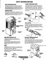
TOXIC EXHAUST GASES
A WARNING: Accidental starting can cause injury
A WARNING: Carbon monoxide (CO) Is a deadly gas!
III dIIath!
•
Ensure that the exhaust system is adequate to expel gases
discharged from the engine. Check the exhaust system
regularly for leaks and make sure the exhaust
manifolds/water-injected elbow is securely attached.
• Be sure the unit and its surroundings are well ventilated.
Run blowers when running the generator set or engine.
• Do not run the generator set or engine unless the boat is
equipped with a functioning marine carbon monoxide
detector that complies with ABYCA-24. Consult your
boat builder or dealer for installation of approved
detectors.
• For additional information refer to ABYC T-22
(educational information on Carbon Monoxide).
•
Disconnect the battery cables before servicing the engine/
generator. Remove the negative lead first and reconnect
it last.
• Make certain all personnel are clear of the engine before
starting.
• Make certain all covers, guards, and hatches are
re-installed before starting the engine.
IAnERY EXPLOSION
A WARNING: Battery explosion can cauS/J injury
III ",.",!
•
Do not smoke or allow an open flame near the battery
being serviced. Lead acid batteries emit hydrogen, a
highly explosive gas, which can be ignited by electrical
arcing or by lit tobacco products. Shut off all electrical
equipment in the vicinity to prevent electrical arcing
during servicing.
• Never connect the negative (-) battery cable to the
positive (+) connection terminal of the starter solenoid.
Do not test the battery condition by shorting the terminals
together. Sparks could ignite battery gases or fuel vapors.
Ventilate any comparttnent containing batteries to prevent
accumulation of explosive gases. To avoid sparks, do not
disturb the battery charger connections while the battery
is being charged.
• Avoid contacting the terminals with tools, etc., to prevent
burns or sparks that could cause an explosion. Remove
wristwatch, rings, and any other jewelry before handling
the battery.
• Always turn the battery charger off before disconnecting
the battery connections. Remove the negative lead first
and reconnect it last when disconnecting the battery.
A WARNING: Carbon monoxide (CO) is an invisible
odollllSS gas. Inhalation PlOdUCBS flu·like symptoms,
naussa 01 dealh!
•
Do not use copper tubing in diesel exhaust systems. Diesel
fumes can rapidly destroy copper tubing in exhaust
systems. Exhaust sulfur causes rapid deterioration of
copper tubing resulting in exhaust/water leakage.
• Do not install exhaust outlet where exhaust can be drawn
through portholes, vents, or air conditioners. If the engine
exhaust discharge outlet is near the waterline, water could
enter the exhaust discharge outlet and close or restrict the
flow of exhaust. Avoid overloading the craft.
• Although diesel engine exhaust gases are not as toxic as
exhaust fumes from gasoline engines, carbon monoxide
gas is present in diesel exhaust fumes. Some of the
symptoms or signs of carbon monoxide inhalation or
poisoning are:
Vomiting
Inability to think coherently
Throbbing in temples
Dizziness
Muscular twitching
Headache
Nausea
Weakness and sleepiness
BAnERYACID
A WARNING: Sulfuric acid In batteliBS can cauS/J
AVOID MOVING PARTS
stmIf8lnjury /11 death!
•
A WARNING: Rotating parts can cause InJUlY
When servicing the battery or checking the electrolyte
level, wear rubber gloves, a rubber apron, and eye
protection. Batteries contain sulfuric acid which is
destructive. If it comes in contact with your skin, wash it
off at once with water. Acid may splash on the skin or
into the eyes inadvertently when removing electrolyte
caps.
01 death!
•
Do not service the engine while it is running. If a
situation arises in which it is absolutely necessary to
make operating adjustments, use extreme care to avoid
touching moving parts and hot exhaust system
components.
Engines & Generators
ii
SAFETY INSTRUCTIONS
ABYC, NFPA AND USCG PUBLICATIONS FOR
INSTALLING DIESEL ENGINES
• Do not wear loose clothing or jewelry when servicing
equipment; tie back long hair and avoid wearing loose
jackets, shirts, sleeves, rings, necklaces or bracelets that
could be caugbt in moving parts.
• Make sure all attaching hardware is properly tightened.
Keep protective shields and guards in their respective
places at all times.
• Do not check fluid levels or the drive belts tension while
the engine is operating.
• Stay clear of the drive shaft and the transmission coupling
when the engine is running; hair and clothing can easily
be caught in these rotating parts.
Read the following ABYC, NFPA and USCG publications
for safety codes and standards. Follow their
recommendations when installing your engine.
ABYC (American Boat and Yacht Council)
"Safety Standards for Small Craft"
Order from:
ABYC
3069 Solomon's Island Rd.
Edgewater, MD 21037
NFPA (National Fire Protection Association)
"Fire Protection Standard for Motor Craft"
Order from:
NFPA
11 Tracy Drive
Avon Industrial Park
Avon, MA 02322
USCG (United States Coast Guard)
"USCG 33CFR183"
Order from:
U.S. Government Printing Office
Washington, D.C. 20404
HAZARDOUS NOISE
A WARNING: High nDlse lelll1ls can cause hearing
loss!
• Never operate an engine without its muffler installed.
• Do not run an engine with the air intake (silencer)
removed.
• Do not run engines for long periods with their enclosures
open.
A
WARNING: Do nDt work Dn machinery when YDU are
IfIBIIta/Iy or physically IncapaCitated by fatigue!
OPERATORS MANUAL
Many of the preceding safety tips and warnings are repeated
in your Operators Manual along with other cautions and
notes to highlight critical information. Read your manual
carefully, maintain your equipment, and follow all safety
procedures.
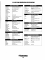
GASOUNE ENGINE AND GENERATOR INSTALLATIONS
Preparations to install an engine should begin with a
thorough examination of the American Boat and Yacht
Council's (ABYC) standards. These standards are a
combination of sources including the USCG and the NFPA.
Sections of the ABYC standards of particular interest are:
H-2 Ventilation
P-I Exhaust Systems
P-4 Inboard Engines
E-9 DC Electrical Systems
All installations must comply with the Federal Code of
Regulations (FCR).
~
WESTERBEKE
Engines & Generators
iii
INSTALLATION
When installing WESTERBEKE engines and generators it is important that strict
attention he paid to the following information:
CODES AND REGULATIONS
Strict federal regulations, ABYC guidelines, and safety codes must he complied with
when installing engines and generators in a marine environment.
SIPHON-BREAK
For installations where the exhaust manifold/water injected exhaust elbow is close to
or will he helow the vessel's waterline, provisions must he made to install a siphonbreak in the raw water supply hose to the exhaust elbow. This hose must he looped a
minimum of 20" above the vessel's waterline. Failure to use a siphon-break when
the exhaust l1Ul1Iifold injectiDn POI1 is oJ or below the load woJerline will result in
raw water domage to the engine aad possible /Wading of the boaJ.
If you have any doubt about the position of the water-injected exhaust elbow relative
to the vessel's waterline under the vessel's various operating conditions, install a
siphon-break.
MI1'E: A siplwn-break requires periodic inspection and cleaning to ensure proper
operation. Failure to properly maintain a siphon-break can result in catastrophic
engine domage. Consult the siplwn-break manufacturer for proper maintenance.
EXHAUST SYSTEM
The exhaust hose must he certified for marine use. The system must he designed to
prevent water from entering the exhaust under any sea conditions and at any angle
of the vessels hull.
A detailed Installation Manual is furnished with the generator. The
Operators manual also has specific installation data for the 3.0 generator.
~
WESTERBEKE
Engines & Generators
iv
AVAILABLE FROM
YOUR WESTERBEKE
DEALER
TABLE OF CONTENTS
Parts Identification ....................................................2
Testing For Dverhaul... ............................................... .3
Troubleshooting Gulde ................................................4
Disassembly Procadures ............................................6
Sealants And Lubricants ............................................7
Torque Specifications .................................................9
Spacial Tools ............................................................. 11
Servlca Standardslllepair Limits .............................. 12
Engine Disassembly .................................................. 15
Inspactlon And Measurement ..................................20
Englna Assembly .......................................................27
011 Pump ....................................................................32
lubrication System ................................................... 32
Fuel Pump .................................................................33
Fuel Filter .................................................................33
Starter Motor ............................................................34
Carbartor ...................................................................35
Raw water Pump .......................................................36
Engine Tuning ...........................................................38
Engine Adjustments ..................................................39
Compression Test .............................................. .39
Water Pump Belt ............................................... .39
Ignition Timing .................................................. .39
Oil Pressure Test ............................................... .40
Spark Plugs ......................................................... 41
Thermostat... ...................................................... .41
Choke Solenoid ................................................. .41
Valve Clearance ................................................. .42
Timing Belt Replacement!Adjustment... ........... .42A
Electronic Governor ................................................. .43
Shutdown Switches ................................................. .44
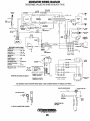
WIring Diagram .........................................................45
AC Generator ............................................................ .46
Specifications ...........................................................47
Metric Conversion Charts ....................................... .48
....v: WESTERBEKE
Engines & Generators
1
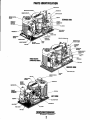
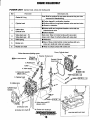
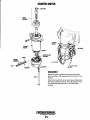
PARTS IDENTIFICATION
~"",.,,,...
COIL
ENGINE SERIAL
'GNmON
,un,.u,__
MODU1£
SERVICE SIDE
I
'CONNECTION
TO COOLANT
RECOVERY
TANK
THERMOSTAT
ASSEMBLY
WATER (COOLANT)
TEMPERATURE
SWITCH
1"'~--- HOSE
OIL DRAIN
+--HEAT
EXCHANGER
FRESHWATER
(COOlANn MODEL
ZINC ANODE
SERVICE SIDE
WAltH PUMP
,,.
IGNITION CONTROL
BAmRY
VOlTAGE
LEFT SIDE
fUEL
DRIP
Engines & Generators
2
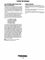
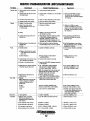
TESTING FOR OVERHAUL
HOW TO DETERMINE ENGINE OVERHAUL PERIOD
OVERHAUL CONDITIONS
Cause of Low Compression
co~pressioln pressure tendsdt0alincrease ahli \:-':::"e in a new
engme untl piston f1ngs an v ve seats a v- ~ b
b k '
Thereafter, it decreases gradually with the p""~geen rfo en 10.
~ ress 0 wear
of thesep arts .
Generally, the time at which an engine should be overhauled
is detennined by various conditions such as lowered engine
power output, decreased compression pressure, and increased
fuel and oil consumption. The lowered engine power output
is not necessarily due to trouble with the engine itself, but is
sometimes caused by improper oil, clogged filters or a faulty
carburetor.
When decrease of compression pressure reac::: ---e tl . .
' must be overh au led .
-0.1 S lelepalr
· . th
Imut,
e engIne
The engine requires overhaul when oil consL.~ t'
. h' I
.
.
....·.IIpIOI1IS 19l
blowby eVident, and compression values are ~t ..
'
mlmmum or
beow.
1
The decrease in compression pressure is caused by many factors. It is. therefore, necessary to detennine a cause or causes
on the basis of data produced by periodic inspection and
maintenance. Oil analysis on a seasonal basis is a good
means of monitoring engine internal wear. When caused by
worn cylinders or piston rings, the following symptoms will
occur:
1
2
3
4
5
Low engine power output
Increased fuel consumption
Increased oil consumption
Hard engine starting
Noisy engine operation
These symptoms often appear together. Symptoms 2 and 4
can result also from improper fuel regulation or a faulty carburetor. They are caused also by defective electrical devices
such as the battery, starter or spark plugs. Therefore it is
desirable to judge the optimum engine overhaul time by the
lowered compression pressure caused by worn cylinders and
pistons plus increased oil consumption. Satisfactory combustion is obtained only under sufficient compression pressure.
If an engine lacks compression pressure, incomplete combustion of fuel will take place even if other parts of the engine
are operating properly. To detennine the period of engine
overhaul, it is important to measure the engine compression
pressure regularly. At the same time, the engine speed at
which the measurement of compression pressure is made
should be checked because the compression pressure varies
with engine rpm. The engine rpm can be measured at the
front end of the crankshaft.
NOTE: To test engine compression see the ENGINE
ADJUSTMENT section of this manual.
Engines & Gener.tors
3
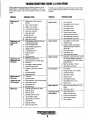
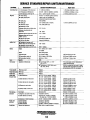
TROUBLESHOOTING GUIDE 3.0 KW BPMG
When toubleshooting indicates an electrical problem, see the
ELECfRICAL SYSTEM WIRING DIAGRAM, as this may
reveal other possible causes of the problem which are not listed
below.
PROBLEM
Engine does not
crank.
Engine starts, runs
and then shuts
down.
Engine starts, runs
but does not come
up to speed.
Engine cranks but
lalts to starl
(Engine wiIl crank
lor 15 seconds)
Engine hunts.
The following troubleshooting tables are based upon certain
engine problem indicators and the most likely causes of the
problems
PROBABLE CAUSE
1. Voltage drop at starter solenoid
terminal.
2. Main 10 amp fuse blown.
4. Battery is low or dead.
5. Loose battery connections.
6. Faulty wire connection.
7. Faulty start switch.
B Faulty pc board
9. Faulty starter solenoid
10. Water filled cylinders.
1. Faulty shutdown switch,(oil pressure,
or exhaust temperature).
2. Faulty overspeed switch.
3. Dirty fueVwater separator filter.
4. Clogged fuel line.
5. Low oil level in sump.
6. Faulty fuel pump.
7. No fuel
B. Clogged fuel filter
1. Faulty mag-pickup sensor.
2. Electronic governor controller faulty,
3. Fuel pump.
4. Fuel supply to engine restricted.
5. Actuator linkage binding.
6. Actuator or electrical connections
faulty.
7. Air intake restricted.
B. Exhaust restricted.
1. Out of fuel.
2. Engine is flooded.
3. Faulty carburetor. (See Carburetor page)
4. Faulty choke solenoid
5. Faulty ignition coil.
6. Bad spark plugs
1. Controller gain adjustment needed.
2. Faulty fuel pump.
3. Faulty PC board.
4. Improper drive belt tension.
5. Low DC battery voltage.
6. High exhaust back pressure.
7. Dirty fuel filter
B. Generator overload.
9. Valves need adjustment.
PROBLEM
PROBABLE CAUSE
Engine misfires.
1. Poor quality fuel.
2. Faulty ignition control module.
3. Dirty flame arrester.
4. Faulty ignition wires.
5. Spark plugs are worn.
6. Binding actuator linkage.
7. High exhaust back-pressure.
B. Valve clearances are incorrect.
9. Valve clearances are incorrect.
Engine backfires.
1. Faulty ignition control module.
2. Incorrect timing.
3. Engine is flooded. See Engine is
flooded under Engine cranks but
fails to start.
4. Dirty flame arrester.
5. Faulty ignition coil.
6. High exhaust back-pressure.
Engine overheats.
1. Blockage in cooling water flow: inspect
the raw water intake, intake strainer,
pump impellers, and look for broken or
seperated hoses.
2. Belts may be loose or broken.
3. Obstructed by-pass hose.
Low oil pressure.
1. Low oil level.
2. Wrong SAE type oil in the engine.
3. Oil diluted with fuel.
4. Relief valve is stuck.
5. Faulty oil pump.
6. Faulty engine bearings.
7. Boat heeled over too much.
B. Faulty oil filter.
High oil pressure.
1. Dirty oil or wrong SAE type oil in the
engine.
2. Relief valve is stuck.
No DC charge to the
starting battery.
1. Faulty connections to
battery charging control.
2. 20 amp fuse blown/faulty.
3. Faulty voltage regulator.
4. Faulty magneto.
Engines & Generators
4
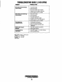
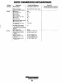
TROUBLESHOOTING GUIDE 3.0 KW BPMG
PROBLEM
PROBABLE CAUSE
Blue Exhaust Smoke Discharge
from Ihe Engine
1.
2.
3.
4.
5.
Lube oil is diluted.
High lube oil level.
Crankcase breather hose is clogged.
Valves are worn or adjusted incorrectly.
Piston rings are worn or unseated.
Black exhausl smoke Discharge
from the Engine
1.
2.
3.
4.
5.
6.
Dirty flame arrester.
Faulty carburetor.
Idle mixture jet too rich.
Accelerator diaphragm leaking.
Valves are worn or incorrectly adjusted.
Piston rings are worn or unseated.
Poor perlormance
at generator speed
1. Contaminates in carburetor.
2. Faulty fuel pump/contaminated.
3. Electronic governor controller needs
adjustment.
Starler stays energized
alter starl
1. Faulty MPU suspected. Check MPU.
2. Faulty starter solenoid.
Unit starts and runs
at Idle speed
1. Check MPU signal. 1.5 - 2.0 VAC cranking.
2. Faulty overspeed board.
Note: MPU voltages to PC board:
Cranking: 1.5 - 2.0 VAC
Running: 4.0 - 5.0 VAC
(2200 rpm)
~
WESTERBEKE
Engines & Generators
5
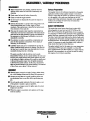
DISASSEMBLY I ASSEMBLY PROCEDURES
DISASSEMBLY
•
•
•
•
•
•
•
•
Before disassembly and cleaning, carefully check for
defects which cannot be found after disassembly and
cleaning.
Drain water, fuel and oil before disassembly.
Clean or wash the engine exterior.
Do not remove or disassemble the parts that require no
disassembly.
Perform disassembly in a proper order using proper tools.
Keep disassembled parts in order. Apply oil when
necessary. Take special care to keep the fuel system parts
from intrusion of dust and dirt.
Parts must be restored to their respective components from
which they were removed at disassembly. This means that all
parts must be set aside separately in groups, each marked for
its componen~ so that the sarne combination or set can be
reproduced at assembly.
Pay attention to marks on assemblies, components and
parts for their positions or directions. Put on marks, if
necessary, to aid assembly..
Carefully check each part or component for any sign of
faulty condition during removal or cleaning. The part will
tell you how it acted or what was abnormal about it more
accwately during removal or cleaning.
The parts assembled with the silicone can be easily
disassembled without use of a special method. In some case,
however, the sealant between the joined surfaces may have
to be broken by lightly striking with a mallet or similar tool.
A ftat and thin gasket scraper may be lightly hammered'
in between the joined surfaces. In this case, care must be
taken to prevent damage to the joined surfaces. For removal
of the oil pan, use a special "oil pan remover".
Surface Preparation
Thoroughly removes all substances deposited on the gasket
application surfaces using a gasket scraper or wire brush.
Check to ensure that the surfaces to which the silicone gasket
is to be applied is ftat. make sure that there are no oils,
greases and foreign substances deposited on the application
surfaces. Do not forget to remove the old sealant that
remains in the bolt holes.
GASKET INFORMATION
The engine has several areas where form-in-place RTV
silicone gaskets are used such as LOCTITE 598 or GE
RTV 100. To ensure that the gasket fully serves its purpose,
it is necessary to observe some precaution when applying the
gasket. Bead size, continuity and location are very important.
Too thin a bead could cause leaks and too thick a bead could
be squeezed out of location causing blOCking or narrowing of
the fluid feed lines. To eliminate the possibility of leaks from
a joint, it is necessary to apply the gasket evenly without a
break while observing the correct bead size.
The gasket material used in the engine is a room temperature
vulcanization (RTV) type and is supplied in a 140z (400
gram) applicator/tube. The RTV hardens as it reacts with the
moisture in the atmospheric air and can be used for sealing
both engine oil and coolant assemblies.
ASSEMBLY
•
•
•
•
•
Wash all parts, except for oil seals, O-rings, rubber sheets,
etc., with cleaning solvent and dry them with pressure air.
Always use tools that are in good condition and be sure
you understand how to use them before performing any
job.
Use only good quality lubricants. Be sure to apply a coat
of oil, grease or sealant to parts as specified ..
Be sure to use a torque wrench to tighten parts for whieh
torques are specified.
When the engine is assembled, new gaskets and O-rings
must be installed.
Engines & Generators
6
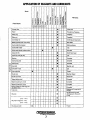
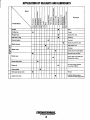
APPLICATION OF SEALANTS AND LUBRICANTS
~
Items
~
.~
Cl
~
~
.<=
-0
~
<:
lil
e
Cl
0
~
-0
-0
"0 III"0
III
Parts Name
~
~
g-g
-0
"0
0
Sill
H
F F ~F
j
E
"
III
~
.<=
I-
I
~ " ~ "
.3
E i
Cl
-0
0
0
III
1342 1373B 1741 1207B 518
~
~
E
.~
::;;
III
0
~
~
0
U
Cl
Connecting rod
Metal (Cylinder block. crank case)
Crank shaft (thrust place)
•
Crank shaft oil seal
•
Valve stem seal (IN, EX)
Retainer
Valve spring seat
Valve spring
0
UJ
Cam pulley bolt
Rocker arm
•
•
10
•
•
•
•
•
•
•
•
•
•
•
•
•
Tappet adjust screw
Washer (rocker arm, 1=0.5),
Washer (rocker arm, 1=2.5)
Spring Jrocker arm, free length 30
mman 51 mm}
Fuel pump
Oil pump
(01.5 - to.7)
Oil pump O-ring (ot.5 - 8,5)
(ot.5 - 15.5)
•
WESTERBEKE
Engines & Generstors
7
oS
UeD
en
,~
.3
Inside wall
Ring groove, Periphery
Periphery
Periphery
Inside big and small ends
Both sides
Sliding surfaces
Lips
Shaft, Stem head
Ups
Complete
Complete
Complete
Bearing. cam
Lips
Thread
~
~
Remarks
(jj
Joint part
•
•
•
•
•
•
•
•
•
•
Rocker arm shaft
Oil pressure switch
I
KS·.. 5900
Piston pin
:0 Camshaft
Q)
c Camshaft oil seal
'6>
c
"
"
'0,
Q17
Piston ring
-"
0
~
~
-0"
iN "8
Cl
j 8.~
E~
en
1 I . 1 o~ -
Piston
Valve (IN, EX)
i5
W
Cylinder liner
Crank case cylinder mating surface
i5
Bearing. Slipper
Shaft, side
Complete
Complete
Complete
Complete
Periphery of a-ring, end of
plung_er
2ml at Suction port and
discharge port, Boss part
a-ring
Thread
APPLICATION OF SEALANTS AND LUBRICANTS
.,
0
Items
"e
.~0
.,
.."'
"C
c
0
Parts Name
"C
c
0
ID
ID
"e
~
~
g-g
~
co
"C
c
0
.!!lID ID
"j
"C
H "e "
..1)
,'
F F 1lF F .9
"C
c
0
ID
~
0
E
"iii
~
0
0
m
E
.,
"C
E
"
"l(l
e
"
c
~
~
ID
E
.!!I
."e .2., .c,c.,
l(l w
0
:i10
e
"
0
•
•
Solenoid switch
c:
Spark plug cap
•
Starter motor
go
W
Starter case
"
"C
.~
'"~
en"
" "c
•
Remarks
"C5
~
u;
E~
oS
0., --;;Co
~,;;
en o~
""...
]
.900
Seal
Thread
Inside (Pour 1ml)
Periphery
Tenninal
•
Spark plug insertion part
High lentian cord
Termin~1
•
•
Spread at pinion part slightly
Bolt and screw for Reel
•
Friction plate, reel shaft part,
Spiral spring, rachel
•
Starter seal rubber
•
Engine oil
Ollpan gasket
Bolt (upper pump case)
'"
.,
~
•
Filter cap, O-ring
.,.,
~.,
;;
•
•
Qilliher
Plunger ass'y
(5
C
0
1342 I373B 1741 12ll7B .18 G17
Oil fiher boh
0
::E
•
•
Thread
•
Upper pump case
,..yo
Oil; at oil change 1000rnl
at overhaul 1200ml
WESTERBEKE
Engines. & G.enerators
8
Impeller sliding surfaces
Joint part for water pipe guide
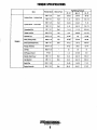
TORQUE SPECIFICATIONS
Item
Thread size
Bo~
or Nut
N-m
Tightening Torque
kg-m
Ib-ft
M8 x 1.25
Bo~
28-30
2.&-3.0
20-22
M& x 1.0
Boll
8-10
0.8-1.0
5.8-7.2
M8 x 1.25
Boll
23-25
2.3-2.5
17-18
M8 x 1.0
Boll
8-10
0.8-1.0
5.8-7.2
Connecting Rod
M7 x 1.0
Boll
11-13
1.1-1.3
8.0-9.4
Tappet Lock Nul
M8 x 0.75
Nul
6-8
0.8-0.8
4.4-5.8
Flywhael Cup
M18 x 1.5
Nul
70-90
7-9
51-65
Drive [Timing) Pulley
M28 x 1.0
Nul
34-38'
3.4-3.6
25-28
M8 x 1.0
Bo~
10-12
1.0-1.2
5.&-&.7
Plunger Assembly
M16 x 1.5
-
19-21
1.9-2.1
.12-15
Oil Filter
M20 x 1.5
-
1&
1.&
13
PTI/&
-
7-9
0.7-0.9
5-8
Cylinder Head Cover
M6 x 1.0
Boll
8-10
0.8-1.0
5.8-7.2
Inlel Manifold
MS x 1.0
Bo~
8-10
0.S-I.0
5.8-7.2
SparkPiug
M12 x 1.25
-
15-20
1.5-2.0
11-15
Engine Assembly
M8 x 1.25
Boll
29-31
2.9-3.1
21-22
Cylinder Block - Cylinder Head
Cylinder Block - Crank Case
Engine
Driven (Camshaft) Pulley
Oil Pressure Switch
Engines & Generators
9
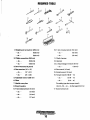
REQUIRED TOOLS
~~~y~
~jP~~~
~~p~ ~
15
17
1. Straight-point screwdriver (200 mm)
10. T·bar universal wrench (10 mm)
- do. -
(150 mm)
- do. -
(12 mm)
- do. -
(100 mm)
- do. -
(13 mm)
2. Phillips screwdriver (200 mm)
11. Plastic hammer
- do. -
(150 mm)
12. Hammer
- do.-
(100 mm)
13. L·shape hexagon wrench (8 mm)
- do. -
3. Set of wrenches (6 pieces)
4. Box wrenches (10 x 13)
(10 mm)
14. Box wrench (16 mm)
- do. -
(17 x 21)
15. Socket wrench (16 mm)
- do.-
(21 x 23)
16. Torque wrench (100 N - m)
5. Adjustable wrench (300 mm)
-do.-
(12N-m)
6. Pliers
- do.-
(5 N - m)
7. Needle-nose pliers
Pre-setting type box torque wrench
8. Snap ring pliers
(10 mm, 7N - m) .... for the tappetiock nut
9. T-bar' socket wrench (10 mm)
- do. -
(12 rnfTl)
- do.-
(13 mm)
- do.-
(17 mm)
17. Socket wrench set
",y"
WESTERBEKE
Engines & Generators
10
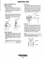
USING SPECIAL TOOLS
5. How to Use Special Tools
2. Piston pin tool
1. Flywheel cup puller
<D When
After removing the piston pin clip, insert the tip of
the piston pin tool into the piston pin hole and
disassembling
Fasten the tools
® and I8i to the flywheel
with
lightly tap the other end of the tool with a hammer.
the tlolls iQ) and remove the magneto nut
Hold the piston with your hand to prevent damage
(right- hand screw) with the socket wrench of
to the connecting rod. (When inserting the piston
the correct size 24.
pin again, take the same care as removing.)
Next. screw tool 0 into tool
I8i and
Piston pin
tighten 0
with the socket wrench of the correct size 24.
Piston pin tool
The flywheel can be removed. Be sure to
use baHs (D),
.'
/~
-;://
«~
r:::Y'
5°
3. Piston slider
•
This tool is to be used for inserting the piston into
the cylinder. After inserting the piston into the
tapered end of the piston slider. set the piston
slider together with the piston tightly on the top of
the cylinder and insert the piston into the cylinder
by pushing the piston crown with fingers.
@When reassembiing
Before replacing the flywheel make sure that
Note:
Don t stop inserting the piston into the cylinder
until all the piston rings enter the cylinder.
the magneto key has properly been set. After
setting the washer and nut on the crank shaft.
fasten tools@and B>to the flywheel and tighten
the nut.
Piston slider
TIghtening torque: 70-90 N-m (7.0-9.0 kg-m)
(51-65Ib-ft)
---Ifl---J t---f'l-
Engines & Generators
11
Top 01 cylinder
SERVICE STANDARDS/REPAIR LlMITS/MAINTENANCE
Part Name
Cylinder Head
Cylinder
Piston
Check/lnsaect
1. Carbon deposit on the combustion
chamber
2. Scratch depth and distortion of the
mounting surface.
3. Seizure
3. Replace or use an over-sized piston
after boring the cylinder.
4. Scratch and wearing down in the
cylinder liner.
4. When the liner cannot be repaired by means
of #400·#600 sandpaper because it is
extremely scratched or scored, or the
difference between the maximum wear and
minimum wear is 0.06mm (0.0024in) or more.
5. When the depth of scratch or distortion
in/of the mating suriace is O.lmm (0.004in)
2. Carbon deposit on the piston crown
and in the piston ring groove.
3. Scratch on the sliding suriace.
4. Measurement of clearance between
the piston ring and ring groove.
Piston Pin
Crankshaft
2. Scratch depth or distortion is O.lmm (0.004in)
or more.
3.
4.
1.
2.
5. Mating suriaces of the cylinder and
cylinder head.
or more.
1. Outside Diameter
5. Measurement of diameter of the
piston pin hole.
1. End Gap
NOTE: Measurement of the end gap:
when no ring gauge is available,
measure the lower part of the
cylinder bore.
a) Top
b) Second
c) Oil
1. Outer diameter
1.Deflection of the crankshaft.
Both the main bearings of the
crankshaft should be supported
with V·blocks.
2. Outer diameter of the crankpin.
3. Outer diameter of the bearing.
4. Oil clearance of the bearing.
5. Side clearance of the crankshaft.
Repair limit
1. Remove carbon deposit and clean.
3. Corrosion in the mated surface.
4. Clogged cooling water passage.
1. Deposit in the water jacket.
2. Wear of the inside cylinder
diameter. Measure the bore with
a cylinder gauge
0) Measure the diameter at a point
7mm above the lower end of the
piston skirt.
b) Piston Clearance
Piston Ring
Standard ValueJMalntenance
Repair or replace depending on the situation.
Clean and remove foreign matters.
Clean and remove foreign matters.
59.00mm (2.3228in)
1. Diameter: 58.960mm (2.3213in)
b) Piston clearance: 0.020·0.055mm
(0.0008-0.0022in)
2. Remove carbon residuum and clean.
3. Repair with #400·#600 sandpaper depending
on the situation.
4. Top: 0.04·0.08mm (0.0016·0.0031in)
2nd: 0.03·0.07mm (0.0012·0.0028in)
Oil: 0.01·0.18mm (0.0004· 0.0071in)
NOTE: To be replaced wifh a new oil ring, when
replacing with new top and/or second rings.
Sandpaper means water proof pap.,
5. Clearance between pin and hole
Loose: 0.002·0.012mm (0.00008·0.00005in)
1. Replace with new piston ring n wear of the
cylinder liner is within the repair limit.
a) Top: 0.15·0.35mm (0.006·0.014in)
b) Second: 0.30·0.50mm (0.012·0.020in)
c) Oil: 0.20.Q.7mm (0.008·0.028in)
2. Repair (set /240·#400 sandpaper
the suriace plate and pOlish the
surface for repair. Use #600 sandpaper
for finishing).
2. 59.06mm (2.3252in) or more
(If wear is exceeding the repair limit,
replace or bore the cylinder and finish
by honing. Over-sized piston is O.Smm.
refer to item 4).
4. Bore and hone to 059.5KO.Olmm
(02.3425 ±0.0004in).Use oversize
piston and rings.
5. Use 1400 sandpaper on the suriace
plate and pOlish the suriace. Use #600
sandpaper for finishing.
1. Outer Diameter: 58.90mm (2.3189in)
or more.
b) Piston Clearance: 0.15mm
(0.0059in) or more
4. Top: 0.10mm (0.004in) or more
2nd: 0.09mm (0.0035in) or more
Oil: 0.21mm (0.0083in) or more
5. 0.04mm (0.0016in) or more
1. 16.00mm (0.6299in)
1. Less than 0.05mm (0.002in)·both ends.
0) Top: 0.5mm (0.020in) or more
b) Second: 07mm (0.028in) or more
c) Oil Ring: to be replaced with a new
oil ring. when replacing with new top
and/or second rings. Sandpaper
means water proof paper.
1. 15.97mm (0.629in) or less.
1. 0.05mm (0.002in) or more.
2. 29.98mm (1.1803in)
3. 31.99mm (1.2594in)
4.0.012· 0.044mm (0.0005· O.OOI71n)
5. 0.1 • 0.2mm (0.004 ·0.008in)
2. 29.95mm (1.17910) or less.
3. 31.97mm (1.259in) or less.
4. 0.06mm (0.002in) or more.
5. 0.6mm (0.024in) or more.
-..v: WESTERBEICE
Engines & Generators
12
SERVICE STANDARDSIREPAIR LlMITS/MAINTENANCE
Part IIaIIIe
Connecting Rod
Magneto
Check/lllSllect
1. Inner diameter of the small end.
2. Oil clearance of the big end.
3. Side clearance of the big end.
• Inition liming
• Spark performance
•
•
•
•
Spark plug
Spark gap
Alternator output
Resistance of coils
Battery
148 - 2220
12.5 - 18.80
• ESG for high speed
• ESG for low speed
• Resistance of primary coil
between black wire and orange wire
• Resistance of secondary coil
between high tension cord and core
Output
2) Commutator under-cut
3) Commutator diameter
Capacity
Operation of thermostat
Pump Impeller
Worn-out, crack
Pump Case liner Worn-out
Guide Plate
Worn-out
Intake Valve
1) Valve Clearance
Exhaust Valve
2) Outer diameter of valve stem
3) Inner diameter of valve guide
4) Clearance to valve stem
5) Contact width of valve seat
Rocker Arm
and Shaft
Timing Belt
1. 16.04mm (0.631 in) or more.
0.27 - 0.410
Clutch
Valve Spring
Camshaft
1. 16.01mm (0.630in)
2. 0.Q15 - 0.041mm (0.0006 - 0.0016in)
3.0.1 - 0.25mm (0.004 - 0.01 in)
BTDC 5' - 5' (electric ignition advance)
10mm (0.4in) or more/500 rpm
(measured by genuine spark tester.
NGK DCPR6E
0.8 - 0.9mm (0.032 - 0.035in)
12V. 130W (5000 rpm)
Between white wire and yellow wire
1) Brush length
Fuse
Thermostat
Repair Limit
Between red-white wire and
black wire
Between black-red wire and blue wire
Between yellow-red wire and
yellow -red wire
Ignition Coil
Standard Value/Maintenance
Free length
1) Height of cam (both IN and EX)
2) Outer diameter of bearing
3) Clearance of holder (bearing)
1) Inner diameter
2) Outer diameter
3) Shaft Clearance
Tension and appearance
2. 0.060mm (0.002in) or more.
3. 0.6mm (0.024in) or more.
1.2mm 9 0.0047in) or more
1.40 - 2.100
Restricting at 6250 rpm
Reducing at 2000rpm
0.26 - 0.350
6800 - 102000
12V -70AH to 12V -100AH
12VO.6KW
Over-running clutch
1) 12.5mm (0.49in)
2) 0.5-0.8mm (0.02-0.03in)
3)30mm (1.18in)
120A
• Start to open: 60'C ± 1.5'C
(140 ± 3'F)
• Temperature at which valve opens
full: 75'C (167'F)
Replace
Replace
Replace
IN: 0.13 - 0.17mm (0.005 - 0.007in)
EX: 0.18 - 0.22mm (0.007 - 0.008in)
IN: 0.13 - 0.17mm (0.005 - 0.007in)
EX: 0.18 - 0.22mm (0.007 - 0.008in)
IN: 0.13 - 0.17mm (0.005 - 0.007in)
EX: 0.18 - 0.22mm (0.007 - 0.008in)
IN: 0.13 - 0.17mm (0.005 - 0.007in)
EX: 0.18 - 0.22mm (0.007 - 0.008in)
IN: 0.13 - 0.17mm (0.005 - 0.007in)
EX: 0.18 - 0.22mm (0.007 - 0.008in)
35mm (1.38in)
1) 23.90mm (0.94in)
2) Pulley side: 17.98mm (0.0708in)
Oil pump side:: 15.97mm(0.629in)
3) 0.02 - 0.05mm (0.0008 - 0.0020in)
1) 13.01mm (0.512in)
2) 12.99mm (0.511in)
3) 0.006 - 0.035mm (0.00024 -0.00138in)
Wear, crack or lengthen-replace
Engines & Generators
13
1) 9.5mm (0.37in) or less
2) 0.2mm (0.008in) or less
3)29 mm (1.14in) or less
If the valve opens at room temperature •
replace the thermostat.
While immersing the thermostat in water,
raise the water temperature and check the
temperature at which the valve opens.
5.46mm (0.215in) or less
5.44mm (0.214in) or less
5.55mm (0.218in) or more
5.57mm (0.219in) or more
0.07mm (0.0028in) or more
0.10",m (0.004in) or more
2.0mm (0.079in) or more
2.0mm (0.079in) or more
33.5mm (1.319in) or less
1) 23.75mm (0.935in) or less
2) 17.95mm (0.707in) or less
15.95mm (0.628in) or less
3) 0.09mm (0.0035in) or more
1) 13.05mm (0.514in) or less
2) 12.94mm (0.509in) or less
3) 0.6 mm (0.0024in) or less
SERVICE STANDARDSJREPAIR LlMITSIMAINTENANCE
Part Name
Engine Block
Carburetor
Check/lnspect
0.4±0.1 MPa (5±1 kg/cm',71 psi)
Without de-compressor
(rocker arm in EX side is removed)
0.93±0.1 MPa (9.5±1 kg/cm', 135 psi)
•
•
•
•
•
3H8A
23/11.5mm
#68
#135
2.2mm
#42
#115
80'
1-3/4
14mm (0.55in)
•
•
•
•
•
Oil Pump
Standard Value/Malntenance
With de-compressor
Setting mark
ThrottleNenturi bore
Main jet (MJ)
Main air jet (MAJ)
Inner diameter of main nozzle
Slow jet (SJ)
Slow air jet (SAJ)
Opening angle of throttle (at W.O.T.)
Pilot screw (PS) - Blind
Fuell"el (from flange surtace
to float bottom
• Resistance of PTC' heater for
auto-by'tarter at 20' C (68' F)
(·PTC: positive temperature coefficient
thermistor)
• Idle speed (clutch in)
1) Inner diameter of pump body
2) Clearance between outer rotor
and body
3) Height of outer rotor
4) Clearance between rotor and
body side
5) Clearance between outer rotor
and inner rotor
20n
900 rpm
1) 29.04mm (1.143in) or more
2) 0.36mm (0.014in) or more
3) 14.96mm (0.589in) or less
4) O.llmm (0.0043In) or more
(incl. wear of the pump cover)
5) 0.16mm (0.006in) or more
...v: WESTERBEKE
Engines & Generators
14
RepaIr LImit
Pay heed to pressure leak in compression
from lhe rolation, sliding and sealing parts.
190
ENGINE DISASSEMBLY
...
0
I'
"
Bolts, nuts, and washers are indicated by the symbols below,
H820 Na La W6 SW6 Screw 620 -
Hexagon headed bolt
Normal hexagon nut
Hexagon lock nut
Plain washer
Spring washer
Pan headed screw
Diameter a mm Length 20 mm
Diameter 8 mm
Diameter a mm
Diameter 6 mm
Diameter 6 mm
Diameter 6 mm Length 20 mm
Removing Parts
Alternator
Oil strainer
<D Remove
<D Cut
the hose band and then remove the oil
0
0
N
., ........
'v;;"
h.
~
....
't'
l - ~32- ~3SHoIo
v_ - <1115- <112OHoIO
14
Thickness: 30 or more
Unit: mil
Setting board for power ynit
the alternator fitting screw
and then remove the
strainer with the hose from the nipple.
I- ~35- ~4OHoh
a~ernator.
Pulser coil
<D Remove
the pulser coil fitting screw
and then remove the pulser coil.
Startor motor and starter solenoid
<D Remove the starter motor fitting bolt
and then remove the starter motor.
@ Pull the starter solenoid from the electric
bracket.
Ignition coil
Rectifier
<D Remove the plug cap from the spark plug,
<D Remove
the rectifier fitting bolt
then remove the rectifier.
@ Remove the ignition coil fitting bolt
and then remove ignition coil.
C. D. Unit
<D Remove the C.D. unit fitting bolt
then remove the C.D. unit.
Magneto flywheel cup
<D Remove
the fiywheel cup with a special tool
according to the instructions of "How to Use
Carburetor
Special Tools~
<D Remove
the carburetor fitting bolt
and then remol(e the carburetor together with
the air silencer, insulator and gaskets.
Fuel pump
<D Remove the fuel pump fitting bolt
th en remove the fuel pu mp.
Engines & Generators
15
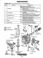
ENGINE DISASSEMBLY
POWER UNIT
Cylinder head. valves and relating parts
Part name
NO
Check point. etc.
Gasket & O-ring
Note: Must be replaced by new parts whenever they are once
removed for·disassembling.
1
Cylinder head
• Carbon deposit in combustion chamber
• Surface width and roughness between valve seat and valve
• Scratch or distortion
2
Intake valve
Exhaust valve
3
Valve stem seal - IN
Valve stem seal - EX
.Surface width and roughness between valve seat and
intake/exhaust valve
.Carbon deposit
Black color: Wear of contact surface with valve stem
Green color: Wear of contact surface with valve stem
4
Valve spring
.Weekness
5
Rocker arm
6
Rocker arm shaft
.Wear of three contact points: contact surface with cam.
rocker arm shaft and rocker arm washer.
• Wear of contact surface with rocker arm
Cover. Cylinder head
Valve clearance adjusting screw
WID» 4-stroke Engine 011
Rock nut
5.
~,,~
Washer. Rocker arm
~
arm
18-10 N
3. Valve stem seal-IN
(Black color)
ml
ml
H625-218-10 N -
1. Cylinder head
ml
~~.'---'
1...::::::::1
...~u".ln
118-10 N-
~Ht'
D
~
ml
3. Valve stem seal-EX
(Green color)
6. Rocker arm ~n'UT_IN
Rocker arm shaft-EX
VIEW FROM UNDER BASE FRAME
Engines & Generators
16
ENGINE DISASSEMBLY
POWER UNIT
Crank shaft, pistons, cylinder/crank case and related parts
NO.
Check point, etc.
Part name
1
Crankshaft
• Oil clearance at main bearings
• Oil clearance at big end of connecting rod
Note: Align the tab of the metal bearing with the notch in the
cylinder/crank case
Note: There are two type of metal bearings
(Thickness code: Black color and Brown color)
2
Connecting rod
Note: Pay attention to the connecting rod orientation for
reassembling
("UP" mark must face the magneto side)
3
Connecting rod cap
Note: Mate the markings of the cap and connecting rod with
each other ("UP" mark must face the magneto side)
4
Connecting rod bolt
Note: Tighten the bolts in ·careful manner;
Gradually tighten the two bolts alternately several times
so thatthey are evenly tightened.
5
Piston
Note: Pay attention to the piston direction
("UP" mark faces the magneto side)
6
Piston pin clip
~
Note:
Don~ use the clip that is once removed.
Be sure to use a new part for reassembling.
Loctite "518"
fi2iiiIDi 4-stroke Engine Oil
CYlinder
Metal bearing
---,:-------11
1.
3. Connecting rod cap
Crankcase
4. Connecting rod bolt
111-13N
ml
ml
Oil strainer
H630-6
/8-10 N -
ml
Engines & Generators
17
ENGINE DISASSEMBLY
~~
~J PISTON RINGS
~,~ o
o
@
CONNECTING ROD
~PISTON
ENGINE DRIVE PUllEY---l-__
SPRING TENillONER
\t ~ff~'JQ:::J:ol
ENGINE DRIVE
PULLEY
SHEAVE ARRANGEMENT
VIEW FROM UNDER BASE FRAME
Engines & Generators
18
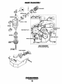
ENGINE DISASSEMBLY
POWER UNIT
NO.
Cam shaft, oil pump and related parts
Part name
Check pOint:etc.
1
Cam shaft
• Smooth movement of decompressor weight
Note: This part is very wfi)akagainst impact.
2
Timing belt
Note: Be sure to keep clean free from oil and grease
3
Drive pulley
Note: Be sure to keep clean free from oil and grease
Note: Pay attention of direction
("UP' mark faces the magneto side)
4
Driven pulley
Note: Be sure to keep clean free from oil and grease
Note: Pay attention of direction
("UP" mark faces the magneto side)
5
Oil pump
MD> 4..troke engine 011
HEAT EXCHANGER
2. Timing beft
ASSEMBLY
26mmNut
Mark
...I....
4. Driven pulley
m/~
/34-36N
Lock washer
ZINC ANODE
-~_.:r
~
PJate--@
Mar~
3. Driven pulley ~
Plate-®
I
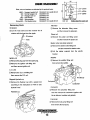
HEAT EXCHANGER (FRESH WATER COOLED MODELS)
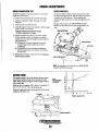
The heat exchanger should be removed, inspected, and
cleaned. Install a new zinc and fresh hoses with new clamps
at reassembly. If suspect, a local automotive radiator shop
should be able to clean and pressure test the heat exchanger.
[=""1--
1. Cam chaft
Decompressor
weight ----tI.o
The water injected exhaust elbow should be removed and
inspected for defects and corrosion. Also inspect the siphon
break hose and its connections.
Flush out the coolant recovery tank and its connecting hose.
Loosen the raw water pump, remove the drive belt and then
remove the raw water pump.
Remove the engines coolant pump. For servicing, refer to
COOLANT PUMP.
5. Oil pump
Remove the thermostat assembly and clean the interior
chambers. Inspect the seals in the pressure cap when
reassembling. Replace the thermostat and gasket.
Engines & Generators
19
J
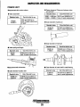
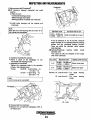
INSPECTION AND MEASUREMENTS
POWER UNIT
• Piston clearance (Clearance between piston
and cylinder)
Measurement with vernier calipers
Standard value
• Valve seat width
Standard value
1.0mm
0.0393 in
Out of the limit to use
0.020 - 0.055 mrn If 0.15 mm (0.0059 in) or
0.0008 - 0.0022 in more, it needs replacement.
Out of the limit to use
If 2.0 mm (0.079 in) or
more, it needs replacement
or repair.
• Outer diameter of piston pin
Standard value
16.00mm
0.6299 in
Out of the limit to use
If 15.97 mm (0.629 in) or
less, it needs replacement.
• Outer diameter of crank pin
Standard value
• Valve spring free length
Standard value
35mm
1.38 in
29.98mm
1.1803 in
Out of the limit to use
less, it needs replacement.
• Outer diameter of crank shaft in metal bearing
Standard value
• Outer diameter of piston skirt
58.960mm
2.3213 in
If 29.95 mm (1.179 in) or
less, it needs replacement.
If 33.5 mm (1.319 in) or
Measurement with micrometer
Standard value
Out of the limit to use
31.99 mm
1.2594 in
Out of the limit to use
If 58.90 mm (2.3189 in) or
less, it needs replacement,
~
WESTERBEKE
Engines & Generators
20
Out of the limit to use
If 31.97 mm.(1.259 in) or
less, it needs replacement.
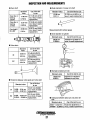
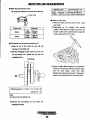
INSPECTION AND MEASUREMENTS
• Cam shaft
• Outer diameter of rocker arm shaft
Standard
value
Outer dia. in
bearing
(Upper)
Outer dia. in
bearing
(Lower)
Cam height
IN&EX
17.98mm
0.708 in
15.97mm
0.629 in
23.90mm
0.94 in
Out of the limit
to use
Out of the limit to use
Standard value
12.99mm
0.511 in
If 17.95 mm (0.707
in) or less, it needs
replacement.
If 12.94 mm (0.509 in) or
less, it needs replacement.
If 15.95 mm (0.628
in) or less, it needs
replacement.
If 23.75 mm (0.935
in) or less, it needs
replacement.
Measurement with cylinder gauge
• Inner diameter of cylinder
Out of the limit to use
Standard value
59.00mm
2.3228 in
.A
• Valve stem
IN
Standard
value
Out ofthe limit
to use
5.48mm
If 5.46 mm (0.215
in) or less, it needs
replacement.
0.216 in
EX
If 59.06 mm (2.3252 in) or
more, it needs replacement.
5.46 mm
0.215 in
If 5.44 mm (0.214
in) or lE!ss, it needs
replacement.
• Diameter of piston pin hole
Standard value
16.002mm
0.630 in
Out of the limit to use
Depends on clearance
between pin and hole.
• Clearance between valve guide and valve stem
Standard value
Out of the limit
to use
IN
0.008 - 0.04 mm
0.003 - 0.0016 in
If 0.07 mm (0.0028
in) or more, it needs
replacement.
EX
If 0.10 mm (0.004
0.025 - 0.057 mm in) or more, it needs
0.0010 - 0.0022 in replacement.
• Clearance between piston pin and piston pin
hole
Standard value
Out of the limit to use
0.002 - 0.012 mm
If 0.04 mm (0.0016 in) or
0.00008 - 0:0005 in more, it needs replacement.
Engines & Generators
21
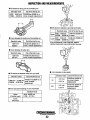
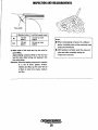
INSPECTION AND MEASUREMENTS
ru
• Oil clearance at big end of connecting rod
Standard value
Out of the limit to use
0.015 - 0.041 mm
0.0006 - 0.0016 in
If 0.060 mm (0.002 in) or
more, it needs replacement.
• Oil clearance between cam shaft and holder
Standard value . Out of the limit to use
• Inner diameter of small end of connecting rod
Standard value
16.01 mm
0.630 in
Out of the limit to use
Upper
0.02 - 0.05 mm
0.09 mm (0.0035 in)
0.0008 - 0.0020 in or more
Lower
0.02 - 0.05 mm
0.09 mm (0.0035 in)
0.0008 - 0.0020 in or more
If the oil clearance is out of the limit, replace
cylinder head and/or cam shaft and/or oil pump.
If 16.04 mm (0.631 in) or
more, it needs replacement.
• Inner diameter of rocker anm
Standard value
13.01 mm
0.512 in
Out of the limit to use
If 13.05 mm (0.514 in) or
more, it needs replacement.
• Inner diameter of valve guide
• Oil clearance between rocker arm and shaft
Standard value
Standard value
Out of the limit to use
If 0.06 mm (0.0024 in) or
0.006 mm - 0.035 mm
more, it needs
0.00024 - 0.00138 in
replacement.
5.51 mm
IN
0.217 in
5.51 mm
EX
0.217 in
• Inner diameter (bearing) of cam shaft holder
If 5.55 mm (0.218 in)
or more, it needs
replacement.
If 5.57 mm (0.219 in)
or more, it needs
replacement.
EX
Standard value
Upper
(Cylinder head)
Out of the limit to use
18.01-18.025 mm
0.709 - 0.710 in
Lower
(Oil pump)
IN
~
WESTERBEICE
Engines & Generators
22
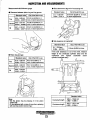
INSPECTION AND MEASUREMENTS
Measurement with thickness gauge
• Side clearance at big end of connecting rod
Standard value
• Clearance between piston ring and ring groove
Standard value
Top
0.1 - 0.25mm
0.004 - 0.D1 in
Out of the limit to use
Out of the limit to use
If 0.6 mm (0.024 in) or more,
it needs replacement.
0.04 - 0.08 mm
If 0.10 mm (0.004 in) or
0.0016 - 0.0031 In more, tt needs replacement.
0.03 - 0.07 mm
If 0.09 mm (0.0035 in) or
Second 0.0012 - 0.0028 in more, it needs replacement.
Oil
0.01 - 0.18 mm
If 0.21 mm (0.0083 in) or
0.0004 - 0.0071 In more, it needs replacement.
• Side clearance of crankshaft
Out of the limit to use
Top
0.15 - 0:35 mm
0.006 - 0.014 In
If 0.5 mm (0.020 in) or
more, tt needs replacement.
Second
0.30 - 0.50 mm
0.012 - 0.020 in
If 0.7 mm (0.028 in) or
more, It needs replacement.
Oil
0.20 - 0.70 mm
0.008 - 0.028 in
Out of the limit to use
0.1 - 0.3 mm
0.004 - 0.012 in
0.6 mm (0.024 in) more
If the side clearance is out of the limit, measure
length of the crankcase (cylinder side) and the
crankshaft
and
replace
crankshaft
and/or
cylinder-crankcase ass'y.
• Piston ring end gap
Standard value
Standard value
Standard value
Note:
• Set the piston ring by pressing it in the piston
crown side.
• To be replaced with a new oil ring when replacing
with new top and/or second rings.
Crankshaft length
126.8 - 126.9 mm
4.992 - 4.996 in
Crankcase length
127.0 - 127.1 mm
5.000 - 5.004 in
Engines & Generators
23
INSPECTION AND MEASUREMENTS
5) Measurement with Plastigage®
• Oil clearance between crankshaft and metal
bearing
1) Wipe oil out of:
• Crankshaft bearing journals
• Metal bearings (both sides)
• Bearing portions of cylinder and crankcase
2) Install metal bearings into the cylinder and
crankcase.
Note:
Align the tab of the bearing with the notch
the cylinder and crankcase.
® in
Standard value
Out of the limit to use
0.012 - 0.044 mm
0.0005 - 0.0017 in
0.06 mm (0.002 in) or less
If the oil clearance is out of the limit, measure
inside diameter of the cylinder/crankcase bearing
holders and the crankshaft bearing journals.
There are within the standard value, replace
metal bearings .
• Cylinder/Crankcase
bearing holder inside
diameter code
The codes (2 sort) are stamped on the upper
side of the crankcase.
o
3) Install the crankshaft to cylinder.
4) Place a piece of the plastigage on the
crankshaft main bearing journal.
5) Assenble the crankcase.
TIghten the crankcase bolts to the specified
torque in the indicated order.
Torque:
: 23-25 N - m (2.3-2.5 kg - m)
(17-18Ib - ft)
: 8-10 N - m (0.8-1.0 kg - m)
(5.8-7.2 Ib - ft)
I.D. code
Standard value
A,X
35.000 - 35.008 mm
1.3780 - 1.3783 in
B,Y
35.008 - 35.016 mm
Black color paint
1.3783 - 1.3786 in
Remark: I.D. code A and B -
Note:
Do not crank up the crankshaft.
~----;;:;~*7{::~tl~
6) Disassemble the crankcase.
7) Measure the compressed plastigage width at
its widest point.
~
Brown color paint
For upper
holder
I.D. code X and X - For lower
holder
I
Plastigage
Appling metal bearing
WESTERBEKE
Engines & Generators
24
bearing
bearing
INSPECTION AND MEASUREMENTS
• Metel bearing thickness code
The codes are painted on the side of the bearing.
/Colorcode
Standard value
Out of the limit to use
0.Q15 - 0.041 mm
0.0006 - 0.0016 in
H 0.06 mm (0.002 in) or
less, it needs replacement
~====-~
• Repair of valve seat
1) Plane the valve seat face with the 45
seat cutter.
Color code
1.488 1.494 mm
0.0586 - 0.0588 in
Black
1.494- 1.500mm
0.0588 - 0.0590 in
valve
2) Depending on the situation (the contact
position of the seat is too high or too low), use
0
0
the 30 cutter or 60 cutter and then repair the
0
surface area with the 45 cutter.
Thickness
Brown
0
• Oil clearance at big end of connecting rod
1) Wipe oil out of the crank pin and big end
bearing of connecting rod.
2) Set the Plastigage to the crank pin and fit it to
the conneCting rod. Tighten the bo~ with the
specified torque.
Plastigage
3) Apply Prussian Blue compound (or equivalent)
evenly on the seat face. While turning the valve
with the valve lapper, check face. width
between the valve and valve seat. If necessary,
repair the face width with the valve seat cutter.
Tightening torque: 11-13 N-m (1.1-1.3 kg-m) .
(8.0-9.4 Ib - ft)
Note:
Do not tum the connecting rod.
3) Remove the connecting rod and check the
Plastigage reading.
Engine. & Generstors
25
INSPECTION AND MEASUREMENTS
Facewidlh
Standard value
Limit that needs repair
IN
1.0mm
0.04 in
2.0 mm or more
O.OBin
EX
1.0mm
0.04 in
2.0 mm or more
O.OBin
Notes:
• When using lapping compound of a different
grade, completely wipe out the previously used
compound beforehand .
• After lapping is complete, wash the valve and
: 4) After repair of the valve seat, lap the valve for
good fitting.
Apply lapping compound thinly on the seat and
lap the valve while turning and tapping it with
the valve lapper.
Remarks: Since the lapping compound is supplied
in a set of three grades (coarse,
medium and fine), lap the valve with all
of them in order from coarse, medium
and fine.
valve seat after completely Wiping the
compound out of them.
...-v: WESTERBEKE
Eng/n"s & G"neralors
26
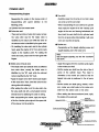
ASSEMBLY
POWER UNIT
Reassembling Engine
• Cam shaft
Reassemble the engine in the reverse order of
disassembling with
• Carefully press the oil pump pin so that it does
careful attention to the
not come out of the cam shaft.
following points.
• When reassembling the cam shaft to the cylinder
(1) Cylinder head and related parts
head, apply the engine oil for the 4-stroke cycle
• Valve stem seal
engine to the cam and bearing beforehand and
• There are two kinds of valve stem seals, namely,
then insert the cam shaft into the cylinder head
the valve stem seal for the intake valve is
from the oil pump side while twisting it with care
identified by the black color while the other for
not to turn over the oil seal lip.
the exhaust valve is identified by the green color.
• Rocker arm
• On installing the valve stem seal to the cylinder
• Temporarily set the tappet adjusting screw and
head, apply the engine oil for the 4-stroke cycle
tappet adjusting nut to the rocker arm.
engine to the insertion point. For setting the
Note:
Set the tappet adjusting nut with the chamfered
side down .
valve stem seal, press it into the valve gUide with
fingers.
• Intake valve, Exhaust valve
• Apply the engine oil for the 4-stroke cycle engine
to the rocker arm shaft.
• The intake valve and exhaust valve are different
from each other, namely the intake valve is
• Set the rocker arm shaft from the side of the oil
identified by the "IN" mark while the exhaust
pump of the cylinder head. Pay heed to
valve is identified by the "EX" mark.
orientation of the rocker arm shaft so that the
tapped hole side is positioned in the oil pump
• Apply the engine oil for the 4-stroke cycle engine
side.
to the valve stem. Then, insert the valve into the
• Set the rocker arm shaft spring, washer, rocker
valve guide while twisting it.
arm, rocker arm shaft collar to the rocker arm
• After setting the cotter on-to the valve stem, tap
shaft from the bottom side in this order.
the valve shaft end with a small plastic hammer
• When selting the above-mentioned parts, apply
several times for stabilizing the cotter in selting.
the engine oil to every part.
• After reassembling the valves, apply the engine
Bolt M6·19
oil for the 4-stroke cycle engine to the upper side
of the retainer and its periphery.
Washer 13.2-21.8-2.0
Rocker arm shaft
Rocker ann shaft collar
Aockerarm
~
WES7ERBEKE
Engines & Generators
27
ASSEMBLY
• Oil pump
• Plunger
• Pour the engine oil of approximately 2.0 ml into
• When setting the plunger stopper into the
the oil pump through the inlet and outlet ports.
plunger case, pay attention to the orientation of
• Apply the engine oil for the 4-stroke cycle engine
the plunger stopper so that it is set as shown.
to the a-rings (1.5-10.70, 1.5-8.50, 1.5-15.50)
• When assembling the plunger assembly to the
and the O·ring at the boss before setting them in
cylinder, fasten it together with the cover.
the oil pump.
• When assembling the oil pump to the cylinder
Tightening torque: 19-21 N-m (1.9-2.1 kg-m)
head, carefully set it so that the cam shaft pin
(12-15Ib - It)
and the notch on the oil pump shaft meet each
other.
Plunger stopper
Cover
• Fasten the oil pump with the three M6 bo~s with
the tightening torque and in the tightening order
specified below.
Tightening order:
<D,
~ and
@
• Piston ring
Tightening torque: 5-6 N - m (0.5-0.6 kg - m)
Fitting oil rings to piston
1. Set the spacer expander in the oil ring groove,
and check to see if both the ends of it correctly
link with each other as shown in <D.
Cam shaft
Oilrin~~
O-Ring~
~
, /1.5-15.5
CORRECT
~
1.5-8.5
+-<i~
Oil rOUTJ
Oil nNJ
Oil pump
Engines & Generators
28
ASSEMBLY
2. While holding down the slit of the spacer
Check of correct selling of each piston ring
expander with a thumb, set the upper rail as its
1. Check to see if the slit of each piston ring is not
slit is deviated from the slit of the spacer
set in the piston thrust direction or piston pin
expander
at
an
angle
of
90· in
the
direction.
counterclockwise direction. ®
2. After the assembling work is complete, make sure
3. In the same manner as the preceding step, set
that each piston ring is set as shown once again.
the lower rail as its slit is deviated from the slit of
the spacer expander at an angle of 90· in the
• Piston and Connecting rod
clockwise direction. ®
• Assemble the connecting rod and connecting
Chrome
rod cap to each other as they were put together
plating
before
removing.
(Before
removing
the
Tapered
connecting rod cap, be sure to leave a marking
at a mated point between the connecting rod
and connecting rod cap as a reference for
reassembling.)
of spacer eXDand!er II
• The upper sides of the connecting rod cap,
Riling compression rings to piston
connecting rod and piston are identified by the
Fit the compression rings onto the piston in the
·UP" mark.
correct order to start with the lower ring. Set each
• For inserting the piston and connecting rod
compression ring. with the side marked with the
assembly intQ the cylinder, use the piston slider.
brand and size up.
Apply the engine oil for the 4-stroke cycle engine
to the cylinder liner, piston rings before inserting
the assembled piston.
Oversize mark.
Brand mark
Engines & Generators
29
ASSEMBLY
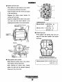
• Cylinder and Crank case
6
• When fitting the metal bearing to the cylinder
and crank case, set the tab in the notch.
2
• Apply the engine oil for the 4-stroke cycle engine
to the metal bearing.
• Degrease the mating surface between the
cylinder and crank case.
3
• Apply the Locktight #518 to either of the cylinder
and crank case with careful attention to the
Tightening torque:
applying part and width so as to avoid overflow.
M8 bolt: 28-30 N - m (2.8-3.0 kg' - m)
Apply Locktight #518 to the black part.
Applying width: 1 mm
(20-22lb - tt)
M6 bolt: 8-10 N - m (0.8-1.0 kg - m)
o
(5.8-7.2Ib - tt)
=
otll======~
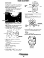
• Cylinder head cover
Carefully avoid
• Fit the gasket to the cylinder head cover and
overflow.
apply the Three Bond #1207B to the shaded
part shown.
Apply the sealanllo the shaded part.
Shaded part (Part shown by slanled lines)
• Fitting cylinder head to cylinder
Tightening torque: 8-10 N-m (0.8-1.0 kg-m)
• Before fitting the cylinder head to the cylinder,
(5.8-7.2Ib - It)
set the piston at the top dead center.
• When fastening the cylinder head, carefully
tighten the bolts with the specified tightening
torque and in the correct order.
30
ASSEMBLY
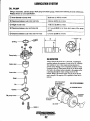
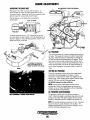
e Oil filter
e Fuel pump
• Make sure that the marks "2" and "0" on the
• Apply the engine oil for the 4-stroke cycle engine
driven pulley and the mark" \1" on the cylinder
to the rubber seal of the oil filter.
head are aligned in a straight line.
• Apply the engine oil for the 4-stroke cycle engine
to the top of the plunger and O-ring of the fuel
· pump.
Crank shaft holder
FILTER WRENCH
OIL FILTER
Tightening torque: 18 N - m (1.8 kg - m)
(131b - ft)
Tightening torque: 5-6 N - m (0.5-0.6 kg - m)
• Water Injected Exhaust
Elbow
(3.6-4.3 Ib - ft)
~<:b,
., ,,
I,~,~)
e Drive pulley
• For tightening the nut to· fasten the drive pulley,
use the crank shaft holder.
~
Tightening torque: 34-36 N-m (3.4-3.6 kg-m)
(25-26 Ib - ft)
lock washer
•!
(Bend it by a part.)
Crank shaft
Plate
Drive pulley
PULLEY BOLT
25-30Nm
• After tightening the nut, bend up the lock washer
by a part.
~
WESTERBEKE
Engines & Generators
31
~
OIL PAN
• Oil Pan
Coat the new gasket with
three bond #12078 on both sides
and mount the oil pan. TIghten
the cap screws gradually in
opposing order.
Torque at 28 - 30 Nm (20 - 22 Ib-ft)
LUBRICATION SYSTEM
OIL PUMP
Using a micrometor, cylinder gauge, depth gauge and feeler gauge, measure the following oil pump clearances.
Replace if wom or out of specification.
<D Inner diameter of pump body
29.04 mm (1.143 in) or more
@ Clearance between outer rotor and body
0.36 mm (0.014 in) or more
@ Heigth of outer rotor
14.96 mm (0.589 in) or less
@ Clearance between rotor and body side
0.11 mm (0.0043 in) or more (incl. wear of the pump
cover)
@ Clearance between outer rotor and inner rotor
0.16 mm (0.006 in) or more
O-Ring
--~«b>-~
@
@>
$~
•
@
@
Pump body
OIL INSPECTION
--~
Inner rotor
Always observe the old oil as it is removed. A yellow/gray
emulsion indicates the presence of water in the oil. Although
this condition is rare, it does require prompt attention to
prevent serious damage. Call a competent mechanic if water
is present in the oil. Water present in the oil can be the result
of a fault in the exhaust system attached to the engine andlor
a siphoning through the water cooling circuit into the
exhaust, filling it up into the engine. Use an oil test kit and
send a sample of the engine oil to a qualified oil test lab for
analysis.
~
I
S~4
Pin
WIPE THIS SURFACE
CLEAN BEFORE
/lV~/~Ll./lV" FILTER
c(?
~~
Oil pump cover
OIL FILTER ASSEMBLY
PRESSURE SWITCH
---c.
~
WESTERBEKE
Engines & Generators
32
FUEL SYSTEM
FUEL PUMP
DISASSEMBLY
Before disassembly, make a aligning line on the out
side of fuel pump for correctly reassembling.
Valve body
CD Remove screw, and take off:
Inspection:
.Wear and damage
• Outer plate
• Gasket
• Valve body
@ Turn the piston clockwise or counter clockwise
until you look the pin from the cutaway of the
pump body.
@ Pull the pin, and remove from the pump body:
• Piston
• Spring
• Diaphragm
• Spring
Diaphragm
Pump body
Inspection:
• Crack and damage
_L----------~
ENGINE
FUEl
FILTER
________
Inspection:
• Burst, crack and swelling
~
REASSEMBLY
"1!!t;;!I~_ LUBRICATE WITH
Reassembly is reverse order of disassembly
CLEAN FUEL AND
PRESS THE FILTER
ON OVER THE a-RING
Note:
After connecting the diaphragm rod to the piston
with pin, align the diaphragm holes (6) to the
pump body holes so that the pin will not come out
through pump body cutaway.
Engines & Generators
33
STARTER MOTOR
"'=~- SNAP
RING
PINION
ASSEMBLY
"..
..
~
.•..
STARTER
MOTOR
MOTOR
BRUSH HOLDER
ASSEMBLY
(-J TO Q"7·~"V
(+J POSITIVE FROM
BATTERY
DISASSEMBLY
Remove the snap ring from the end of the shaft and the
pinion assembly can be disassembled from the front of the
housing.
Remove the long bolts from the motor base and disconnect
the wiring connection hardware. This will separate the base
from the housing allowing access to the brush holder
assembly.
...v"
WESTERBEKE
Engines & Generators
34
CARBURETOR
DE-RICHENING
DC nCUULo,un.
MIXTURE JET
SCREEN
REMOVE E-R1NG TO
ACCESS THE SCREEN
FOR CLEANING
/+---n"---:'Ilr- BOWL
DRAIN
LEVER
KEEP THE LINKAGE
WELL LUBRICATED
'ArTHATn.
DESCRIPTION
The carburetor is a single barrel, side-draft type with a
cleanable metal screen air intake filter/spark arrester.
Fuel Overflow Chamber
The choke is operated by a 12 VDC solenoid. The choke
solenoid is activated when the start switch is depressed and is
controlled by the I.C.M.
Excess fuel drains into the fuel overflow chamber but is
drawn out again at start-up. This chamber should be kept free
of contaminates. Cleaning every 250 operating hours should
be sufficient unless there is a fuel problem.
Air ScreenJFlame Arrester
The air screen can easily be removed. Clean after the first 50
hours of operation and every 100 hours from then on. Clean
the air screen in a water soluble cleaner such as GUNK.
Idler Mixture Jet
Adjustment is performed with the generator operating.Screw
the jet slowly in until it seats, then back it out 2 to 3 turns.
Maximum adjustment is 5 turns.
NOTE: An idle mixture jet adjusted too far off its seat can
induce a sooty exhaust discharge at engine start-up and
shut-down.
De-Richening Valve
The de-richening valve closes off a fuel port that is supplying
additional fuel on a cold start after start up. This is a thermal
electric device that slowly moves a needle outward when
DC power is applied after start up to close this fuel port.
To check this valve, remove from the carburetor (cold) and
apply DC voltage across its electrical connections. The
devise should get hot and the needle will slowly move
outward. the devise will remain hot during engine operation
Carburetor Bowl Drain
A bowl drain slotted plug is located on the lower right comer
of the carburetor bowl. This is located just inboard of the
actuators ball joint/clevis.,
CARBURETOR WITH SPEED ACTUATOR
-...v: WESTERBEKE
Engines & Generators
35
RAW WATER PUMP
DESCRIPTION
SCREWS
Coolant (fresh water) cooled generators have dual water
pumps while the raw water cooled models use a single water
pump. The pumps are essentially the sarne. The upper pump
mounts to the top of the lower pump and has a tang on the
shaft that fits into the shaft of the lower pump. Both pumps
are driven simultaneously by the engines drive belt.
The following instructions apply to either pump:
IMPELLER
INSPECTION: CHECK AT THE BASE OF
EACH BLADE BY BENDING VIGDROUSL~
REPLACE THE IMPELLER IF THERE
ARE ANY CRACKS.
INSPECT THE D·RING
AND IMPELLER. REPLACE
IF ANY SIGNS OF WEAR
OR TEARING
PUMP OVERHAUL
Disassembly
The pump when removed from the engine will have the hose
attachment nipple threaded into the inlet and outlet ports of
the pump along with a drive pulley attached to the shaft of
the pump. remove these attachments noting their positions
before starting the pump disassembly.
1. Remove the four cover plate screws, cover plate, and
sealing O-ring.
IMPELLER PIN
FITS INTO SHAFT
SHAFT
Dual Pumps
Remove the cover screws and the cover will separate the
upper pump (raw water) from the fresh water (coolant)
pump as shown in the illustration.
Remove the wear plate to expose the impeller. Notice the
direction the impeller blodes are working in so as to install
the replacement impeller with blodes working in the same
direction.
CIRCLIP
D·RING
INNER
BEARING
2. Remove the impeller using a pair of pliers, grasping the
hub and pulling it out of the pump with a twisting motion.
3. Remove the screw and sealing washer that hold the earn in
place. remove the cam and inner wear plate behind it.
4. Remove the dust plate and circlip.
S. Support the pump body on an arbor press and with a drift,
press the shaft and bearing assembly out of the pulley end
of the pump.
6. Remove the O-ring from the shaft.
7. Support the outer bearing and push the shaft out of the
bearing.
S. Remove the spacer and circlip .
SPACER
OUTER
BEARING
CIRCLIP
DUST
PLATE
""'''''''v
LIGHTLY GREASE THE PUMP
CHAMBER WITH GLYCERIN
~ETSCREW
Inspection
Inspect all parts and replace those showing wear and
corrosion.
PULLEY
Engines & Ge,nerators
36
RAW WATER PUMP
Reassembly
Wipe the inside surface of the pump dry. Apply a film of
glycerin supplied in the impeller kit to the inside pump
surfaces and to the exposed area of the shaft lip seal.
1. Install a new shaft seal in the pump body. Apply some
glycerin to the lip of the seal.
2. Install the circlip on the shaft. Support the outer
bearing and push the shaft into the bearing until the
bearing contacts the circlip
3. Install the spacer against the circlip. Support the inner
bearing and push the shaft into the bearing until it
contacts the spacer.
4. Apply some glycerin onto the O·ring and install it on
the shaft approximately 1/8" away from the inner bearing.
5. Support the pump body on an arbor press. With a twisting
motion, install the shaft and bearing assembly into the
shaft seal until the inner bearing contacts the pump
body. Then assemble into the pump body so that the outer
bearing just clears the boss for circlip.
6. Install circlip and push the shaft and bearing assembly
so the outer bearing contacts the circlip.
7. Install the dust plate.
S. Install wear plate and cam and secure in place with
washers and screw.
DuolPumps
The wear plate is assembled above the impeller.
9. Apply some glycerin to the surface of the impeller
housing, impeller inner surface of the cover plate and
O-ring.
lO.With a twisting motion, install the impeller into the
pump. Install the O·ring and secure the cover with the
four screws.
UPPER
PUMP SHAFT
SCREWS
FASTENS THE
UPPER PUMP
BOOYTO THE
4'1~::::::::~~
WEAR
a-RING GASKET
ONLY NEEDS TO BE
REPLACES IF IT SHOWS'
SIGNS OF AGING.
DUAL PUMPS
ASSEMBLY
SETSCREW
NOTE: Install the new impellers with a rotating motion so the
blades are working in the same direction of those of the
removed impeller.
DuolPumps
Assemble the upper pump to the lower pump as illustrated
making sure the mounting screws are tight.
PULLEY
~
LOWER PUMP
WESTERBEKE
Engines & Generators
37
ENGINE TUNING
TEST RUN AND INSPECTION AFTER COMPLETE ASSEMBLY
After reassembly, the engine must be tuned. This will ensure
that the engine operates at its maximum efficiency.
• Mount the engine on a test bench.
• Connect the electrical wiring. refer to the WIRING
DIAGRAM.
• Connect the air intake line to the air cleaner.
• Connect the exhaust.
• Fill the engine cooling system with coolant and the engine
oil sump with lube oil.
• Connect the fuel lines.
• Crank the engine with the starter (non-ignition operation)
for about twenty seconds. This will pre-lubricate the
engine internal components.
• Start the engine and allow it to run five minutes.
• Remove the cylinder head cover while the engine is
running.
• Check that the engine oil is continuously circulating from
the oil pump to the valve rockers through the cylinder
head.
If there is no oil circulation or if the oil circulation is
sluggish, stop the engine and make the appropriate repairs
and adjustments.
• Re-install the cylinder head cover.
• Check the engine for oil, fuel, coolant, and air intake
leakage.
• Check for abnormal noise and odor.
• Check for abnormal electrical charging.
• Check the engine fastening parts for looseness.
• Check the operation of the start/stop switch and LED
panel lights.
• Adjust the engine speed to the specified value for
generator operation.
• Stop the engine to complete the tuning procedure.
• Additional tightening after test run. Check the tightening
condition of respective bolts and nuts after test run, and
additionally tighten them with the specified tightening
torques.
Engines & Generators
38
ENGINE ADJUSTMENTS
ENGINE COMPRESSION TEST
WATER PUMP BELT
10 check the engine's compression pressure, wann up tl,e
engine, then shut it down.
1. Remove both spark plug caps and both spark plugs.
2. Install a compression adapter and gauge in a spark
plug hole.
3. Close the thru hull valve (seacock).
4. Crank the engine several times quickly so that the gauge
pointer reaches it's maximum.
To remove, replace or adjust the belt, loosen the pivot bolt
and release the adjusting bolt. Slide tlle water pump bracket
to slacken the belt for removal. When replacing and
adjusting the bel~ set the belt very tight and tighten the bolt
and nut.
The dual water pumps on the FRESH WATER COOLED
MODELS use the same drive belt and the adjusbnent is tlle
same.
RAW WATER PUMP
STANDARD COMPRESSION PRESSURE AT 500 RPM:
71 PSI (5± 1 Kg/cm')(D.4± 0.1 MPa)
S. Test the compression pressure on the other cylinder.
If either cylinder is below the standard try adding a
small amount of engine oil through tl,e spark plug hole
and repeat the test.
<a) If additional oil causes an increase of pressure,
the piston ring andlor cylinder may be worn
or damaged.
(b) If additional oil does not increase compression
pressure suspect poor valve contact, valve seizure
or valve wear.
,AD,JUS IIING BOLT
I
I
6. Reinstall the two plugs, connect the wires and open the·
thru hull valve (seacock),
""",
WATER PUMP !t~A,CKE'(
NOTE: The adjusn;l£nt is the same for the FRESH WATER
COOLED MODEL dual pumps.
IGNITION DMING
The magneto employs the electric ignition advance system
that advances ignition timing with an increase of engine
speed. While rurming the engine, check the ignition timing
with a timing light.
There are nine (9) markings (TOC, ATDC 5' and BTDC 5',
10', 15°, 20", 25°, 30°, 35) on the flywheel cup.
Check the timing while observing the position of the carved
marking on the starter case.
FLYWHEEL
30
BTDC
IGNITION TIMING
IN DEGREES
25
20
10
_--:=--___
=
~,...,.-~
.... 7'1"-(.".;;__"--l5r__~CARVED
Engines & Generators
39
5
0
0
3
4
5
Engine speed rpm
MARKINGS
6 X 10 3
ENGINE ADJUSTMENTS
ADJUSTING THE DRIVE BELT
BELT ASSEMBLY VIEWED FROM BENEATH
The engine's drive belt is located under the engine. To
access the belt, for inspection and/or adjustment, remove
the cover as shown. Inspect the belt for wear along the edges
and for proper belt tension (belt should be tight).
The belt tension can be checked by meassuring the
spring length.
11/41n (31
JAM NUT
r-;~'-1
To set the spring tension at 1-114", release the jam nut and
use a rod such as an allen wrench to tum the adjustins nut (as
shown) to tighten or loosen the spring tension, which in turn
adjusts the tension on the belt.
\
ROD
IT IS NORMAL FOR SOME BELT
DUST TO ACCUMULATE IN THE
ENGINE PAN, SIMPLY WIPE CLEAN
COVER
OIL PRESSURE
The lubricating system is a pressure feeding system using an
oil pump. The engine oil is drawn from the oil sump by the
oil pump, which drives the oil, under pressure, through the
oil filter and various lubricating parts in the engine. The oil
then returns to the oil sump to repeat the continuous cycle.
When the oil pressure exceeds the specified pressure, the oil
pushes open the relief valve in the oil pump and returns to
the oil sump, keeping the oil pressure within it's specified
range.
TESTING OIL PRESSURE
To test the oil pressure, remove the oil switch and install a
mechanical oil pressure gauge in it's place, it will be
necessary to connect the two switch wires together for the
engine to run. After wanning up the engine, with the engine
speed at 2200 rpm, read the oil pressure gauge.
OIL PRESSURE: between 30 and 40 psi at 2200 rpm
NOTE: A newly starter (cold) engine may have an oil
pressure up to 40 psi. A wanned engine can have an oil
pressure as low as 30 psi. Oil pressure will vary depending
on the load placed on the generator.
OIL PRESSURE SWITCH/SENSOR
The generator is fitted with an oil pressure shutdown
switch. Should the engine's oil pressure drop below the safe
minimum, the switch will shut the engine down to prevent
damage by interrupting the DC voltage to the ignition coil.
NOTE: The specified minimum oil pressure is 5 psi. A gradual
loss of oil pressure usually indicates worn bearings. For
additional in/omlation on low oil pressure readings, see the
ENGINE TROUBLESHOOTING chart.
l"'f1V'IWESTERBEKE
, Enaines & Generatars
40
ENGINE ADJUSTMENTS
SPARK PLUGS
The spark plugs should be cleaned and re-gapped after the
first 50 hour break-in period, then inspected every 250 hours
thereafter and replaced as needed.
A
WARNING: Do not remove the spark plugs while
the engine is hot. Allow the engine to cool before
removing them.
SPARK PLUG GAP: 0.032 - 0.03510. (0.8 - O.9mm).
SPARK PLUG TORQUE: 11-15Ib-ft (15- 26 Nm).
NOTE: Loctite Anti-Seize applied to the threaded ponion of
the spark plugs will retard corrosion, making future removal
of the spark plugs easier.
GAP
-,tL-_
~
INSPECT FOR
WEAR & CARBON'"
INSPECnNG
THE SPARK
PWGS
INSPECT FOR
DAMAGE
THERMOSTAT [Raw Water Cooled Models]
A thennostat controls the coolant temperature as the raw water
continuously flows through the closed cooling cirCUit. When
the engine is first started, the closed thermostat prevents the
water from flowing (some water is by-passed arOUnd the
thermostat to provide coolant circulation in the engine block).
As the engine warms up, the thermostat gradually opens. The
thermostat is accessible and can be checked, cleaned, or
replaced easily. Carry a spare thermostat and gasket.
If you suspect a faulty thermostat, place it in a pan of water
and bring to a boil. A working thermostat should open when
heated and close when cold.
1;=~'---.-f'LI'Cf'V FOR
DETERIORATION
AND DAMAGE
GASKET
APPLY SEALANT
'. WHEN INSTALLING
CHOKE SOLENOID
The choke solenoid is a 12 volt DC operated unit that
is an integral part of the carburetor. When the engine is cold,
extra fuel is supplied to the engine. 'The choke is controlled
by the ignition control module and requires no adjustments.
ZINC ANODE [Raw Water Cooled Models]
The zinc anode is located just below the thermostat cover
and next to the oil filter. The purpose of the zinc anode is to
sacrifice itself to electrolysis action taking place in the raw
water cooling circuit, thereby reducing the effects of
electrolysis on other components of the system. The
condition of the zinc anode should be checked monthly and
the anode cleaned or replaced as required. Spare anodes
should be carried on board.
THERMOSTAT
ASSEMBLY
ZINC ANOOE
THE GASKET IS SEALED TO
THE CASTING AND, UNLESS
DAMAGED. CAN BE LEFT IN
POSITION. ADD SEALANT TO
THE GASKET SURFACE WHEN
REASSEMBLING THE COVER.
NOTE: Refer to the Cooling System
pages for Fresh Water Cooled Thermostat
and Zinc Anode assemblies.
Engines & Generators
41
ZINC ANODE
AND GASkET
ENGINE ADJUSTMENTS
VALVE CLEARANCE
It is routine maintenance to adjust the valve clearance after
the first fifty hours of operation. Valve clearance adjustment
must be performed when the engine is cool and the piston
must be the top dead center of the compression stroke.
Perform the following adjustment steps:
EXHAUST
SIDE
INTAKE
SIDE
ADJUSTING SCREW
1. Remove the fuel pump and fuel filter from the cylinder
head cover. This assembly can be set aside without
disconnecting the hoses.
FEELER GAUGE
2. Remove the cylinder head cover..
VALVE #2
7. Adjust the intake and exhaust valve clearance for cylinder
#2 using the same sequence.
NOTE: When loosening and tightening the lock nut. hold
the adjusting screw with a valve clearance driver to pre
vent it from moving.
----~-
3. Remove the flywheel cover to access the flywheel and
driven pulley.
TORQUE WRENCH
(PRE-SmING TYPE)
VALVE
CLEARANCE
DRIVER
NOTE: The governor sensor (mag pick-up) wires can be
disconnected at the sid of the control panel.
4. Turn the driven gear and align the '1 and 0" mark on the
driven pulley with the" V" mark on the cylinder head.
~hO:02
8. Install the cylinder head COVet. Apply sealant to the inside
rim of the cover as indicated by the shaded area of the
drawing.
BOLT TORQUE:
8 -10 Nm (0.8 -1.0 kg·m) S.8 -7.2Ib-ft
FLYWHEEl
9. Install the flywheel cover and re-attach the sensor wires.
5. Adjust the intake and exhaust valve clearance for
cylinder # I.
a. Loosen the lock nut.
b. Insert a feeler gauge between the valve end and the
adjusting screw.
c. Set the valve clearance by the adjusting screw.
VALVE CLEARANCE:
INTAKE: 0.13 - D.17mm (D.DDS - D.D07in)
E EXHAUST: 0.18 - D.22mm (0.007 - 0.009in)
SEAL THIS AREA
WITH LOCTITE
BLACK SILICONE
d_ Tighten the lock nut.
e. Again. check the valve clearance.
6_ Tum the driven gear and align the "2 and 0" mark on the
driven pulley with the " V" mark on the cylinder head.
Engines & Generators
42
·
ENGINE ADJUSTMENTS
INSPECTIONJREPLACING OF THE TIMING BELT
If cracks, wear, lengthening or other damage is found,
replace the timing belt.
UMIT OF ElONGATION: MORE THAN 10mm (0.4 IN) DEFLECTION BY
PUSHING WITH YOUR ANGER
Replacement of the Timing Belt
1. Remove the parts in the following order:
a ..Spark plugs
b. Recoil starter
c. Magneto flywheel cup
d. Alternator assembly
e. Alternator bracket
2. "fum the crankshaft and align "0" mark on the drive
pulley and the "0" mark on the cylinder head.
3. Remove the timing belt from the driven pulley side.
4. Install the timing belt from the drive pulley side.
FLYWHEEL CUP
NOTE: After installing the timing belt, when the aligning
"0" marie on the drive pulley with "0" on the cylinder
block. Please conJinn that the "I & 0" or "2 & 0" mark
on the driven pulley are aligned with the "V''' mark on the
cylinder head.
NOTE: Always keep the timing belt away from any oil and
grease.
o
V'MARK
DRIVEN PULLEY
ALTERNATOR BRACKET
TIMING BELT
...v: WESTERBEKE
Engines & Generators
42A
ELECTRONIC GOVERNOR'"
DESCRIPTION
~~~~
CONTROLLER
GOVERNOR
PC BOARO
The system is composed if three basic components.
1. Controller. The PC board that governs the system is
located in the control panel.
2. Sensor. Mounted on the flywheel cover, the sensor measures the speed of the engine (via the ring gear).
3. Actuator. Electronically controls the carburetor throttle.
The sensor and actuator are wired thru the wiring harness to
the controller (PC board).
CONTROL
PANEL
(P2)
(INTERIOR
VIEW)
SPEEO (Pl)
ACTUATOR
FEEOBACK (P4)
'"
Following are the basic procedures for adjusting the speed
(PI). stability (P2), gain (P3), and actuator feedback (P4)
pots.
The adjusting pots (except speed) have physical internal
stops. Tum to the right (clockwise) to increase, tum to the
left (counter-clockwise) to decrease.
Before starting the engine
• Remove all loads and tum off the AC circuit breaker
to insure that loads will not be subjected to voltage
variations while these adjustment are made.
• Decrease the speed pot to prevent overspeed at start up.
• Tum the other adjustment pots to the middle position.
FLYWHEEL COVER
MAGNETIC
(MPU) PN 046874
950 -1000 OHM
Start the engine, monitor speed and adjust to the hertz rating
of the unit by adjusting the SPEED (PI) as needed. Verify
that the AC voltage output is in the correct range.
Decreasing the gain (P3) dampens no load hunting. With the
engine running at no load and proper speed, manually bump
the throttle lever to cause hunting. If necessary, decrease the
gain in small increments to eliminate hunting.
After the engine's no load speed and gain are set correctly,
the AC circuit breaker can be turned on and the ships load
applied. In the event of speed variations with loads applied,
the stability (P2) pot may need adjustment. This adjustment
also changes how the engine responds to generator load
changes.
If the range of adjustment of either gain (P3) or stability (P2)
pots do not correct engine hunting, the actuator feedback
(P4) pot can be increased. This adjustment dampens the signals to the throttle control actuator. Increasing this adjustment
will decrease the amount of throttle control resolution.
Because of this, it is recommended the adjustment be made
in very small increments. The gain and stability pots may
now need to be readjusted.
Most hunting problems occur because of mechanical problems with the linkage between the actuator and the carburetor. Insure that the linkage is free of any debris or corrosion
and that it moves freely. It is recommended that the linkage
be lubricated with a graphite lubricant. Do not use oil
because it tends to collect dirt and dust.
NOTE: Adjustments to one parameter may affect others,
such as speed. It may be necessary to readjust some pots
throughout this process.
SENSOR
FLYWHEEL
RING GEAR
ADJUSTMENT PROCEDURE
Speed. This adjustment is used to raise or lower the
engine's speed. This generator engine is set to run at
2200 RPM.
Gain. Adjusts the overall set of the engine. If too low, the
engine seems sluggish, to high causes the engine to hunt.
Stability. Adjusts the engine's response to generator load
changes.
Alternator Feedback. Adjusts the stability of the speed
signal to the throttle actuator.
NOTE: These adjustments are extremely delicate and require
proper meters for measuring voltage and RPM'S. The
potentiometers are linked and adjustments to one may upset
the balance of another.
Engines & Generators
43
SAFETY SHUTDOWN SWITCHES
SAFETY SHUTDOWN SWITCHES
EXHAUST TEMPERATURE SWITCH
This engine is protected by three shutdown switches and
two fuses. Should a shutdown occur, do not attempt to
restort witlwut finding and co"ecting the cause. Refer to
the heading Engine storts, runs and then shuts down in the
ENGINE TROUBLESHOOTING section of this manual.
An exhaust temperature switch located at the base of the
exhaust elbow sensors an excessive exhaust temperature
(an inadequate supply of cooling water). A temperature
above 240° F will shut the engine down. Inspect the cooling
system, water pump, pump belt, seacock, water strainer,
water hoses, etc. This switch will reset itself when the
exhaust cools.
OVERSPEED SWITCH
The overspeed PC board inside the control panel will shut
the engine down if the engine speed (RPM'S) exceeds the
operating speed required to run the generator. The overspeed
PC board will reset itself once the engine shuts down.
EXHAUST
ELBOW
FUSE
TEMPERATURE
SWITCH
SWITCH
LOW OIL SWITCH
Located just to the righi of the oil filter, this switch Sensors
the engine's oil pressure if the oil pressure falls to below
5 psi. This switch will shut the engine down. Check the
angle of operation, dipstick oil level and oil filter. The switch
will reset itself.
PC BOARD
LOW OIL PRESSURE SWITCH
CONTROL
PANEL
Jrt-r---lftAIN CIRCUIT
BREAKER
MAIN CIRCUIT BREAKER AC 25A
HIGH WATER TEMPERATURE SWITCH
(Fresh Water Cooled Model)
The main circuit breaker at the control panel will
automatically disconnect the AC power if there is an
electrical overload.
This circuit breaker should be manually switched off
when servicing the engine/generator to ensure that no
power is coming into the boat. The breaker is reset
manually.
A high water temperature switch is located at the thermostat
housing. Normally closed, this switch, should the fresh water
coolant's operating temperature reach approximately 2lO'F
(99°C), will open and shut the engine down. This switch
resets itself at 195°F (107°C) .
....--..,~==--
FUSES
CGO'LANT RI'CG~fERY TANK
A lOA fuse located on the side of the control panel protects
the DC electrical wiring. If an electrical overload occurs the
fuse will blow and shut the engine down.
An 20A in-line fuse protects the battery charging circuit. If
this fuse fails, the engine will continue to run but the banery
will not be charging.
THERMqSTAT
HOUSING
~
~))~
lOA FUSE
20A FUSE
BATTERY CHARGING
44
GENERATOR WIRING DIAGRAM
RESISTANCE VALUES IN OHMS IN BLACK ITALIC
tI'
MAGNETIC
PlCKLP
12.5 -IB.51}
_____ EXCiTER COtL
f.4 -2.W
MAG. COIL
eLK/RED
lis BLKIRECI
116 VELIR D
II.
Bl~
'16
., eLK
LK
)
148-2221}
Sill (LOED
IGNITION
MOOULE
PULSERCOIL
Boon
fleRO/HT
~
~
~
..
MAG. PICK·UP :i
Q
I
[l/A
1.4·2.m~
trIAD. COIL'
TlT4
COHTROl PC BOAAD
SPARK
IGMTION
COL
116 ORij
PLUGS
I Hl
6 A
Iii BLU
0.Z6· O.35fl
JGN. CDIL
c'-'2.5',UIl
EXCITER COIL
fla Tn
OIL PRESS
CAAB..ftETOR
'OI.<NOID
FUSE
0.27-0.411}
ALT. COIL
•• i
R(O
SWITCH
20ll
CARS SOLENOID
20 AWl'
8ATHIY
12 YDC
,--40
EXHAUST
lEMPERATUle
SWITCH
UTTEAT
Sil'l TeN
.. ,
.,8
o
"1 GRN/RED
fa
au
HT
ACTUATOR: 3.0·3.' ()
RESISTANCE VALUES IN OHMS
ACTUATOR
MAGNETO COIL. •••••....•••...••••• 1.4· 2.1
'TARm!
o
,14 8LK
SOLENOID
EXCITER COIL. ......................12.5 -18.8
4.7fl
START SOLENDIO
PULSER COIl •••......••••••..••••••. 148· 222
ALTERNATOR COll. .•....•••....•..• O.27 • 0,41
IGNITION COIL. ...................... O.26· 0.35
UGIN[ CONH[CTOR
COlllflOL PC HOARG
run
10J.
(Primary)
MAGNffiC rICK·UP...•..•••....•..•800
START SOLENOID ................... 4.1
I
"8 REDillT
I
HHEL/REWOtE
HIGH TENSION lEADS.............. 6.800·10.DDD
COll~(CTOII
116 BLI(
CARBERATDR SOLENOID .......... 20
tl'
TOLERANCE ± 20%
r+
~
•
•
fl6 ORG
ACTUATOA ........................... 3.0 ·3.1
NOTE: TESTER USED· FLUKE MULTIMEl'ER
+
UNIT CAN
RESTART
uHI r CAN
NOT RESTART
RENOT( SHUTDOWN TERN I HAL
I: POSITIYE 1+1
2: AUX. SfluTDOWH
I
YEl
".
leI ® ct
J: ENERG£/lCl STOP
4: GROUND (.J
JIINPERISI HUST BE ROIGYED
OVERSPEEO PC BOARD (PN «045377)
"
f<D@CD
TERMINALS 1 "2 ARE FOR
"FIREBOY" CDtlNECTION
""
.TERMINALS 3 & 4 ARE FOR
"EMERGENCY STOP SWITCH"
- f0
116 GftM
I
1~2
@ G)
PANEl/REMOTE CONNECTOR
,n
•
2 I
'~'
CONTROL PC BOARD
A
~
.,6 B K
START/STOP
SWITCH
I
PART NUMBERS: REMOTE STOPISTART PANEL N048056 PANEL EXTENSION HARNESS 15FT «048200,30 FT «048201
GREEN TO STARTER GROUND
REO ISOLATION POST
REO ISOLATION POST
WHITE
AC
N
..o,,_j-------,
220V·50Hl
WHITE
GREEN
CONNECTIONS FOR
230V 50Hz
AC OUTPUT CONNECTIONS 120V 60Hz
..... WESTERBEKE
Engines & Generetors
45
L
N
LOAD
AC GENERATOR
MOTOR DATA
The power required to start an electric motor is considerably
more than is required to keep it running after it is started.
Some motors require much more current to start them than
others. Split-phase (AC) motors require more current to start.
under similar circumstances, than other types. They are commonly used on easy-starting loads, such as washing
machines, or where loads are applied after the motor is
started, such as small power tools. Because they require 5 to
7 times as much current to start as to run, their use should be
avoided, whenever possible. if the electric motor is to be driven by a small generator. Capacitor and repulsion-induction
motors require from 2 to 4 times as much current to start as
to run. The current required to start any motor varies with the
load connected to it. An electric motor connected to an air
compressor, for example, will require more current than a
motor to which no load is connected.
In general, the current required to start 115-Volt motors connected
to medium starting loads will be approximately as follows:
MOTOR SIZE
(HP)
AMPS FOR
RUNNING
(AMPERES)
(JTARTIN~)
1/6
3.2
4.6
5.2
7.2
10.2
13
6.4 to 22.4'
9.2 to 32.2'
10.4 to 72.8'
14.4 to 29.2'
20.4 to 40.8'
26 to 52
t/4
1/3
1/2
3/4
PERMANENT MAGNET GENERATOR
Engine rpm at 2200
Generator tums at 3600 (60 Hz). 3000 (50Hz)
60Hz 120 voltsl25 amps. 50 Hz 230 voltsll3 amps
1
AMPS FOR
AMPERES
'NOTE: In the above table the maximum Amps for Starting is
more for some small motors than for larger ones. The reason
A WARNING: Do not attempt to make adjustments or
for this is that the hardest starting types (split-phase) are not
IfIII8/IS ID tIIII f/IIIIIfBfor. the ,eneraIDr Is maintenance
made in larger sizes.
frrIB, «tIIII f/IIIIIfBfor fails (no ac output), contact your
WESrEllBEKE dealer or distributor.
Because the heavy surge of current needed for starting
motors is required for only an instant, the generator will not
be damaged if it can bring the motor up to speed in a few
seconds. If difficulty is experienced in starting motors. tum
off all other electrical loads and, if possible. reduce the load
on the electric motor.
Required Operating Speed
Run the generator first with no load applied. then at half the
generators capacity, and finally loaded to its full capacity as
indicted on the generators data plate. The output voltage
should be checked periodically to ensure proper operation of
the generating plant and the appliances it supplies. To
monitor voltage and load. check it with a portable meter and
ampprobe.
GENERATOR FAILURE
Should a failure occur in the permanent magnet generator,
contact your Westerbeke dealer of the Westerbeke factory.
NOTE: It would be important to inspect the pulley and drive
Generator Maintenance
belt under the generator base frame.
Maintaining reasonable cleanliness is important. Connections
of tenninal boards and rectifiers may become corroded, and
insulation surfaces may start conducting if salts. dust, engine
exhaust. carbon. etc. are allowed to build up. Clogged ventilation openings may cause excessive heating and reduced life
of windings.
In addition to periodic cleaning. the generator should be
inspected for tightness of all connections. evidence of
. ove~eated tenninals and loose Of damaged wires.
Engines &. Generators
46
3.0 KW BPMG GENERATOR SPECIFICATIONS
ENGINE SPECIFICATIONS
COOLING SYSTEM
Engine Type
Two cylinder, four stroke gasoline engine.
General
Water cooled via raw water pump.
Bore & Stroke
2.32 x 2.36 inches (59 x 60 mm)
Raw Water Pump
Total Displacement
20.01 Cubic Inches (.33 liter)
Positive displacement type, rubber impeller,
belt driven.
Bearings
Two main bearings.
1.75 GPM (6.6 LPM) (before thermostat opens)
Valve System
Overhead cam-cross flow.
Raw Water Flow
(into water injected
exhaust elbow)
2.0 GPM (7.5 LPM) (thermostat open)
Compression Ratio
9:1
Operating Temperature
140'F (60'C)
Rring Order
1-2
Aspiration
Naturally aspirated.
Direction of Rotation
Counterclockwise viewed from the back end.
Inclination
250 maximum angle of operation
Dry Weight
1651bs (75 Kg)
Governor
Electronic
AC GENERATOR (SINGLE PHASE)
Type
Permanent magnet (two pole)
Speed
3600 RPMl60Hz
3000RPMl50Hz
3.0 Kw
3.0 KW - 60 Hz single phase, 120 volts
2 wire, 25 amp
3.0 KW - 50 Hz single phase, 230 volts
2 wire. 13 amp
FUEL SYSTEM
Fuel Pump
Mechanical fuel pump.
Fuel
Unleaded 89 octane or higher gasoline.
Ignition liming
BlDC 25' (not adjustable).
Spark Plug Gap
0.032 - 0.035in (0.8 - 0.9mm)
Ignnion Coil
12 volt.
Spark Plug Torque
11 -15Ib-ft (15 - 20 Nm)
Rame Arrester
Metal screen type.
Bolt Torque
See TORQUING THE CYLINDER HEAD.
Garburetor
Single barrel side draft.
Fuel Consumption
(Full Load)
0.4 GPH@ 2200 RPMl25 Amps
Ignnion liming
12-Volt flywheel magneto.
TUNE-UP SPECIFICATIONS
AIR REQUIREMENTS
Engine Combustion
13 CFM (0.287 cmm)
Generator Cooling
200 CFM (5.66 cmm)
ELECTRICAL SYSTEM
Start Motor
12-Volt reduction gear with solenoid.
Starting Batte ry
12-Volt, (-) negative ground
Battery Capacity
600-900 Cold Cranking Amps (CCA)
Battery Charging
11 Amp
DC Amperage Draw
70 Amps DC
FRESH WATER COOLED MODELS
LUBRICATION SYSTEM
Cooling System
Fresh water cooled block, thermostatically
controlled Ihru a heal exchanger.
Fresh Water (coolant)
Pump
Positive displacement, rubber impeller belt
driven
Raw Water Pump
Positive displacement, rubber impeller belt
driven
2.5 - 3.0 GPM
9.5 -11.3 LPM
Type
Wet sump system trochoid type pump.
Oil flfter
Fuel flow. paper element, spin-on disposals.
Oil Capacity
1.5 qts. (91.4 L)
Raw Water Flow
(into water injected
exhaust elbow)
Oil Grade
API SJ 10W-30, 15W-40
Operating Temperature
...v WESTERBEKE
Engines & Generators
47
ENGLISH TO METRIC CONVERSION CHART
MuJUelY Temeerature
De~ree FahrenheiIJ"F)
TO---.9~t eauivalent number of:
Bv
{"F-311l
+ 1.8
DeQree Celsius °C}.
Mullielv Accelerallon
By
To Qel eauivalent number of:
Foot/second'lfl/sec')
0.3048
Meler/second'lm/s'l
Inch/second2{inJsec Z)
0.0254
Meier/second' (mls'l
Muhiply Torque
By
To Qet eQuivalent number of:
Pound-inch Ilb·in.)
0.11298
Newton-melers (N·ml
Pound-foot (Ib·ft)
1.3558
Newton-meters (N·ml
~_guivalent
Mullli1h'_Power
~.
Homepower Ihp)
0.746
KiiowaHs (kWl
Multiply Pressure or Stress
By
To Qet equivalent number of:
at water (in. H
To get
number of:
0)
0.249t
KiloDascals (kPal
Pounds/sauare in. (lbnn.'l
6.895
KiioDaseals (kPal'
MuHiely Energy or Work
By
To aet eauivalent number of:
British Thennal Unit (Btu)
1055
Joules (Jl
1.3558
Joules IJ)
Inches
Foot-oound (ft·tb)
kilowatt-hour IkW·hr)
3,600,000. or
Joules (J = one W/s)
3.6 x 10'
Multiply Light
By
To Qet equivalent number of:
Fool candle ([cl
1.0764
Lumens/melei'(lmlm')
~
TO---.gel eauivalent number of:
Multielv Fuel Performance
Kllomelersililer (kmiLi
MHesiaat (mlle/aan
0.4251
GaUons/miie (aaVmile)
2.3527
LHerlkiiomeler (L/km)
MulHetv Velocity
By
To Qet eQuivalent number of~
Mneslhour Imile/hrl
1.6093
Kilometers/hour Ikmlhr)
MuHlolv Length
By
To Qet equivalent number of:
Inch (in.)
25.4
Millimeters_{mm)
Foot 1ft)
0.3048
Meiers (m)
Yard (vdl
0.9144
Meters (m)
Mlle_ (mile)
1.609
Kilometers Ikm)
MuHiDIv Area
By
To ael equivalent number of:
Inch'l;n.')
6452
MilJimeters~mm2)
Inch'lin.')
6.45
Centimeters2(cm l )
Fool'lft')
0.0929
Melers'lm'l
Yard'lvd')
0.8361
Meters'lm')
Multiply Volume
B.
To get eauivalent number of:
Inch.'lin. 'l
16387
Millimeters'lmm'l
Inch.'/in,')
16.387
Centimeters3( cm 3)
Inch.'/in,')
0.0164
Liters (Ll
Quart lat)
0.9_
Lners (Ll
·G8tlon icaJl
3.785
Liters (Ll
Yard'lvd')
0.7646
Meters'(m'l
Multielv Mass
By
To get eauivalent number of:
Pound lib)
0.4536
Kiloorams (kol
Ton ltoo)
907.18
Kiloorams (kol
Ton lton)
0.907
Tonne II)
MulUelv Farce
By
To get equivalent number of:
K1loo",m Iko\
9.807
Newtons INl
Ounce 102)
0.2780
Newtons INl
Pound Clb\
4.448
Newtons-.lNJ
,... WESTERBEKE
Engines & Generators
48
STANDARD AND METRIC CONVERSION DATA
LENGTH·DISTANCE
Inches tin) x 25.4 = Millimeters (mm) x .0394 = Inches
Feet (It) x .305 = Meters (m) x 3.281 = Feel
Miles x 1.609 = Kilometers (km) x .0621 = Miles
DISTANCE EQUIVALENTS
1 Degree of Latitude = 60 Nm = 111.120 km
1 Minute of Latitude = 1 Nm = 1.852 km
VOLUME
Cubic Inches (in') x 16.387 = Cubic Centimeters x .061 =in'
Imperial Pints (IMP pt) x .568 = Liters (L) x 1.76 = IMP pt
Imperial Quarts (IMP qt) 1.137 = Liters (L) x.88 = IMP qt
Imperial Gallons (IMP gal) x 4.546 = Lhers (L) x .22 = IMP gal
Imperial Quarts (IMP qt) x 1.201 = US Quarts (US qt) x .833 = IMP qt
Imperial Gallons (IMP gal) x 1.201 =US Gallons (US gal) x .833 =IMP gal
Fluid Ounces x 29.573 = Milliliters x .034 = Ounces
US Pints (US pt) x .473 =Liters{L) x 2.113 =Pints
US Quarts (US qt) x .946 = Liters (L) x 1.057 = Quarts
US Gallons (US gal) x 3.785 =Liters (L) x .264 =Gallons
x
MASS·WEIGHT
Ounces (oz) x 28.35 = Grams (g) x .035 = Ounces
Pounds (Ib) x .454 = Kilograms (kg) x 2.205 = Pounds
PRESSURE
Pounds Per Sq In (psi) x 6.895 = Kilopascals (kPa) x .145 = psi
Inches of Mercury (Hg) x .4912 = psi x 2.036 = Hg
Inches of Mercury (Hg) x 3.377 = Kllopascals (kPa) x .2961 = Hg
Inches of Water (H20) x .07355 = Inches 01 Mercury x 13.783 = H20
Inches of Water (H,O) x .03613 = psi x 27.684 = H20
Inches of Water (H20) x .248 =Kilopascals (kPa) x 4.026 =H20
TORQUE
Pounds-Force Inches (in-Ib) x .113 = Newton Meters (Nm) x 8.85 =in-Ib
Pounds·Force Feet (It-Ib) x 1.356 =Newton Meters (Nm) x .738 =It-Ib
VELOCITY
Miles Per Hour (MPH) x 1.609 =Kilometers Per Hour (KPH) x .621
POWER
Horsepower (Hp) x .745 = Kilowatts (Kw) x 1.34 = MPH
FUEL CONSUMPTION
Miles Per Hour IMP (MPG) x .354 = Kilometers Per Liter (Km/L)
Kilometers Per Liter (KmlL) x 2.352 = IMP MPG
MUes Per Gallons US (MPG) x .425 = Kilometers Per Liter (Km/L)
Kilometers Per Lher (Km/L) x 2.352 = US MPG
TEMPERATURE
Degree Fahrenhett ('F) = ('C X 1.8) + 32
Degree Celsius (OC) = (OF· 32) x .56
UQUID WEIGHTS
Diesel Oil = 1 US gallon = 7.13 Ibs
Fresh Water = 1 US g~lIon = 8.33 Ibs
Gasoline': 1 US gallon = 6.1 Ibs
Salt Water = 1 US gallon = 8.56 Ibs
~
WESTERBEKE
Engines. & Generators
49
=MPH
DECIMAL TO METRIC EQUIVALENT CHART
Fractions of
Decimal (in.)
Metric (mm)
Fractions of
an inch
Decimal (in.)
Metric (mm)
1/64
0.015625
0.39688
33164
0.515625
13.09687
1/32
0.03125
0.79375
17/32
0.53125
13.49375
3/64
0.046875
1.19062
35/64
0.546875
13.89062
1/16
0.0625
1.58750
9116
0.5625
14.28750
5/64
37/64
0.578125
14.66437
an inch
0.078125
1.98437
3/32
0.09375
2.38125
19/32
0.59375
15.08125
7/64
0.109375
2.77812
39/64
0.609375
15.47812
1/8
0.125
3.175
518
0.625
15.87500
9/64
0.140625
3.57187
41/64
0.640625
16.27187
5/32
0.15625
3.96875
21/32
0.65625
16.66875
11/64
0.171875
4.36562
43/64
0.671875
17.06562
3/16
0.1875
4.76250
11/16
0.6875
17.46250
13/64
0.203125
5.15937
45164
0.703125
17.85937
7/32
0.21875
5.55625
23132
0.71875
18.25625
15/64
0.234375
5.95312
47/64
0.734375
18.65312
1/4
0.250
6.35000
314
0.750
19.05000
17/64
0.265625
6.74687
49/64
0.765625
19.44687
9/32
0.28125
7.14375
25132
0.78125
19.84375
19/64
0.296875
7.54062
51/64
0.796875
20.24062
5/16
0.3125
7.93750
13116
0.8125
20.63750
21/64
0.328125
8.33437
53164
0.828125
21.03437
11/32
0.34375
8.73125
27/32
0.84375
21.43125
23/64
0.359375
9.12812
55164
0.859375
21.82812
3/8
0.375
9.52500
7/8
0.875
22.22500
25/64
0.390625
9.92187
57/64
0.890625
22.62187
13/32
0.40625
10.31875
29/32
0.90625
23.01875
27/64
0.421875
10.71562
59/64
0.921875
23.41562
7/16
0.4375
11.11250
15116
0.9375
23.81250
29/64
0.453125
11.50937
61/64
0.953125
24.20937
15/32
0.46875
11.90625
31/32
0.96875
24.60625
31/64
0.484375
12.30312
63/64
0.984375
25.00312
1/2
0.500
12.70000
1
1.00
25.40000
"MI'"
WESTERBEKE
Engines & Generators
50
INDEX
AC Generator ........................... 046
Assembly ............................... 27
Assembly Procedures ....................... 6
Camshaft . . . . . . . . . . . . . . . . . . . . . . . . . . . . . . . .19
Carburetor .............................. .35
Choke Solenoid .......................... Al
Compression Test ......................... 39
Cylinder Head Cover .......................30
Disassembly Procedures ..................... 6
Drive Belt Adjustment ..................... AD
Drive Pulley ............................. 31
Electronic Governor ...................... 043
Engine Adjustments ....................... 39
Engine Disassembly ...................... .15
Engine Tuning ............................ 38
Exhaust Valve ............................ 27
Fuel Filter ............................... 33
Fuel Pump . ............................. .33
Fuses ...... , ........................... 044
Gasket Information ......................... 6
Governor-Electric ........................ 043
Heat Exchanger . . . . . . . . . . . . . . . . . . . . . . . . . . .19
Injection Timing ......................... .39
Inspection and Measurement ................ 20
Intake Valve ............................. 27
Lubrication ............................. .32
Metric Conversion Charts .................. 048
Oil Clearance ............................22
Oil Inspection ............................ 32
Oil Pressure ............................ AD
Oil Pump ............................. 28,32
Overspeed Switch .........................44
Parts identification ......................... 2
Piston Rings ............................ .28
Pump-Raw Water ......................... 36
Raw Water Pump ......................... 36
Repair Limits ........................... .12
Required Tools ........................... 10
Resistance Values ........................ 045
Safety Instructions ..................... .1,11,111
Sealants and Lubricants Chart .................7
Shutdown Switches ........................44
Siphon-Break ........................... .IV
Spark Plugs ............................. Al
Special Tools ............................. 11
Specifications ........................... 047
Standard and Repair Limits ................. .12
Starter Motor ............................. 34
Testing for Overhaul . . . . . . . . . . . . . . . . . . . . ... .3
Testing Oil Pressure ...................... .40
Thermostat ............................. Al
Timing Belt ReplacementlAdjustment ......... A2A
Torque Specincations .......................9
Troubleshooting Guide ..................... A
Valve Clearance ......................... 042
Valve Seat ............................... 25
Water Pump Belt ......................... .39
Wiring Diagram ......................... .45
Zinc Anode . . . . . . . . . . . . . . . . . . . . . ........ Al
•
Engines & Generators
51
Engines & Generators
lD92WMDW6JD5