1
OPERATORS MANUAL'
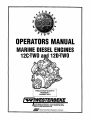
MARINE D'IESEL ENGINES·
a
12C~TWO
120-TWO,
PUBLICATION NO.039717
REVISION 3
JANUARY 2011
..~ WESTERBEKE
,
WESTERBEKE CORPORA TlON • 150 JOHN HANCOCK ROAD
MyLES STANDISH INDUSTRIAL PARK' TAUNTON MA 02780
, W.B,SITE: WWW.WESTERBEKE.COM
.
.L;r
Member National Marine Manu/acturers Association
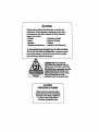
A WARNING ..
Exhaust gasses contain Carbon Monoxide, an odorless anil
colorless gas. Carbon Monoxide is poisonous and can cause
unconsciousness and death. Symptoms of Carbon Monoxide
exposure can Include:
-Dizziness
- Throbbing in Temples
-Nausea
- Muscular Twitching
-Headache
- Vomiting
- Weakness and Sleepiness -Inability to Think Coherently
IF. YOU ORANYONE ELSE EXPERIENCE ANY OF THESE SYMPTOMS,
GET OUT INTO tHE FRESH AIR IMMEDIATELY. If symptoms persist,
seek medical attention. Shut down the unit and do not restart
until it has belln inspected and repaired.
A WARNING DECAL is provided by
WESTERBEKE and should be fixed to a
bulkhead near your engine or generator.
14'!'!"i!O:!!~~~ WESTERBEKE also recommends installing
CARBON MONOXIDE DETECTORS in the
liviltg/sleeping quarters of your vessel.
~":"~_T"" They are inexpensive and easily
L~tEf~lW"~.~·""'~_.J obtainable at your local marine store.
I~
WAR
N· I
NG
CALIFORNIA
PROPOSITION 65 WARNING
Marine diesel and gasoline engine
exhaust and some of its constituents
are known to the State of California
to cause cancer, birth defects,
and other reproductive harm.
SAFETY INSTRUCTIONS
INTRODUCTION
PREVENT BURNS - FIRE
Read this safety manual carefully. Most accidents are
caused by failure to folww fundamental rules and
precautions. Know when dangerous conditions exist and
take the necessary precautions to protect yourself, your
personne~ and your machinery.
follOWing safety instructions are in compliance with
the American Boat and Yacht Council (ABYC) standards.
•
PREVENT ELECTRIC SHOCK
•
A WARNING: File can cause injury 01 death!"
Prevent flash fires. Do not smoke or permit flaines or
sparks to occur near the carburetor, fuel line, filter, fuel
punlp, or other poten!ial sources of spilled fuel or fuel
vapors. Use a suitable container to catch all fuel when
removing the fuel line, carburetor, or fuel filters.
Do not operate without a Coast Guard Approved flame
arrester. Backfue can cause severe injury or death.
Do not operate with the air cleaner/silencer removed.
Backfire can cause sevete injury or death.
Do not smoke or pennit flames or sparks to occur near
the fuel system t(eep the compartment and the
engine/generator clean and free of debris to minimize the
chances of fire. Wipe up all spilled fuel and engine oil.
Be aW\ll'e - diesel fueLw.jj] burn.
The
A WARNING: Do not touch AC electrical connections
•
while engine is lunning, 01 when connected to shore
powel. Lethal voltage is plesent at these connections!
•
•
•
•
•
•
•
•
Do not operate this machinery without electrical
enclosures and covers in place.
Shut off electrical power before accessing electrical
equipment
Use insulated mats whenever working on electrical
equipment.
Make sure your clothing and skin are dry, not damp
(particularly shoes) when handling electrical equipment.
Remove wristwatch and all jewelry when working on
electrical equipment.
Do not connect ntility shore power to vessels AC
circuits, except through a ship-to-shore double throw
transfer switch. Damage to vessels AC generator may
result if this procedure is not followed.
Electrical shock results from handliog a cbarged
capacitor. Discharge capacitor by shorting terminals
together.
•
PREVENT BURNS - EXPLOSION
A WARNING: Explosions flom fuel vapors can cause
injUlY 01 death!
•
•
•
•
PREVENT BURNS - HOT ENGINE
.A WARNING: Do not touch hot engine parts 01
exhaust system components. Alunning engine gets
very hot!
•
•
•
•
Always check the engine coolant level at the coolant
recovery tank.
A WARNING: Steam can cause injury 01 death!
•
• In case of an engine overheat, allow the engine to cool
before touching the engine or checking the coolant.
~
Follow re-fueling safety instructions. Keep the vessels
hatches closed when fueling. Open and ventilate cabin
after fueling. Check below for fumes/vapor before
running the blower. Run the blower for four minutes
before starting your engine.
All fuel vapors are highly explosive. Use extreme care
when handling and storing fuels. Store fuel in a
well-ventilated area away from spark-producing
equipment and out of the reach of children.
Do not fill the fuel tank(s) while the engine is running.
Shut off the fuel service valve at the engine when servicing
the fuel system. Take care in catching any fuel that might
spill. DO NOT allow any smoking, open flames, or other
sources of fire near the fuel system or engine when
servicing. Ensure proper ventilation exists when servicing
the fuel system.
Do not alter or modify the fuel system.
Be sure all fuel supplieiiiave a positivei~i\Utoff valve.
Be certall\ fuel line fittings are adequately tightened and
free ofleaks.
.
Make sure a fire extinguisher is Installed nearby and is
properly maintained. Be familiar with its proper use.
Extinguishers rated ABC by the NFPA are appropriate
for all applications encountered in this environment.
WESTERBEKE
Engines & Generators
•
I
SAFETY INSTRUCTIONS
ACCIDENTAL STARTING
TOXIC EXHAUST GASES
A WARNING: Accidental starting can cause injury
A WARNING: Carbon monoxide (CO) is a deadly gas!
or death!
•
•
Ensure that the exhaust system is adequate to expel gases
discharged from the engine. Check the exhaust system
regularly for leaks and make sure the exhaust manifold!
water-injected elbow is securely attached.
• Be sure the unit and its surroundings are well ventilated.
Run blowers when running the generator set or engine.
• Don't run the generator set or engine unless the boat is
equipped with a functioning marine carbon monoxide
detector that complies with ABYCA-24. Consult your boat
builder or dealer for installation of approved detectors.
• For additional information refer to ABYC T-22
(educational information on Carbon Monoxide).
Disconnect the battery cables before servicing the engine/
generator. Remove the negative lead first and reconnect
it last.
Make certain all personnel are clear of the engine before
starting.
Make certain all covers, guards, and hatches are reinstalled before starting the engine.
•
•
BATTERY EXPLOSION
A WARNING: Battery explosion can cause injury
or death!
A WARNING: Carbon monoxide (CO) is an invisible
•
Do not smoke or allow an open flame near the battery
being serviced. Lead acid batteries emit hydrogen, a
highly explosive gas, which can be ignited by electrical
arcing or by lit tobacco products. Shut off all electrical
equipment in the vicinity to prevent electrical arcing during servicing.
. • Never connect the negative (-) battery cable to the positive (+) connection terminal of the starter solenoid. Do
not test the battery condition by shorting the terminals
together. Sparks could ignite battery gases or fuel vapors.
Ventilate any compartment containing batteries to prevent
accumulation of explosive gases. To avoid sparks, do not
disturb the battery charger connections while the battery
is being charged.
• Avoid contacting the terminals with tools, etc., to prevent
burns or sparks that could cause an explosion. Remove
wristwatch, rings, and any other jewelry before handling
the battery.
• Always tum the battery charger off before disconnecting
the battery connections. Remove the negative lead first
and reconnect it last whenservicing the battery.
odorless gas. Inhalation produces flu-like symptr1ms,
nausea or death!
•
Do not use copper tubing in diesel exhaust systems. Diesel
fumes can rapidly destroy copper tubing in exhaust systems.
Exhaust sulfur causes rapid deterioration of copper tubing
resulting in exhaust/water leakage.
• Do not install exhaust outlet where exhaust can be drawn
through portholes, vents, or aii' conditioners. If the engine
exhaust discharge outlet is near the waterline, water could
enter the exhaust discharge outlet and close or restrict the
flow of exhaust. Avoid overloading the craft.
• Although diesel engine exhaust gases are not as toxic as
exhaust fumes from gasoline engines, carbon monoxide
gas is present in diesel exhaust fume~. S?me o~ the
symptoms or signs of carbon monOXIde Inhalation or
poisoning are:
Inability to think coherently
Vomiting
Throbbing in temples
Dizziness
Muscular twitching
Headache
Weakness and sleepiness
Nausea
BATTERY ACID
AVOID MOVING PARTS
A WARNING: Sulfuric acid in batteries can cause
A WARNING: Rotating parts can cause injury
severe injury or death!
•
or death!
When servicing the battery or checking the electrolyte
level, wear rubber gloves, a rubber apron, and eye protection. Batteries contain sulfuric acid which is destructJve.
If it comes in contact with your skin, wash it off at once
with water. Acid may splash on the skin or into the eyes
inadvertently when removing electrolyte caps.
~
•
Do not service the engine while it is running. If a situation
arises in which it is absolutely necessary to make operating adjustments, use extreme care to avoid touching moving parts and hot exhaust system components.
WESTERBEKE
Engines & Generators
ii
SAFETY INSTRUCTIONS
OPERATORS MANUAL
Many of the preceding safety tips and warnings are repeated
in your Operators Manual along with other cautions and
notes to highlight critical infonnation. Read your manual
carefully, maintain your equipment, and follow all safety
procedures.
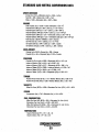
GASOLINE ENGINE AND GENERATOR INSTALLATIONS
Preparations to install a gasoline engine or generator should
begin with a thorough examination of the American Boat and
Yacht Council's (ABYC) standards. These standards are from
a combination of sources including the USCG and the NFPA.
Sections of the ABYC standards of particular interest are:
H-2 Ventilation
H-24 Gasoline Fuel Systems
P-l Exhaust Systems
P-4 Inboard Engines
E-9 DC Electrical Systems
All installations must comply with the Federal Code of
Regulations (FCR).
~
ABYC, NFPA AND USCG PUBLICATIONS FOR
INSTALLING DIESEL ENGINES
Read the following ABYC, NFPA and USCG pUblications
for safety codes and standards. Follow their recommendations when installing your engine.
ABYC (American Boat and Yacht Council)
"Safety Standards for Small Craft"
Order from:
ABYC
3069 Solomon'S Island Rd.
Edgewater, MD 21037
NFPA (National Fire Protection Association)
"Fire Protection Standard for Motor Craft"
Order from:
NFPA
11 Tracy Drive
Avon Industrial Park
Avon, MA 02322
USCG· (United States Coast Guard)
"USCG 33CFR183"
Order from:
U.S. Government Printing Office
Washington, D.C. 20404
WESTERBEKE
Engines & Generators
iii
INSTALLATION
When installing WESTERBEKE engines and generators it is important that strict
attention be paid to the following information:
CODES AND REGULATIONS
Strict federal regulations, ABYC guidelines, and safety codes must be complied with
when installing engines and generators in a marine environment.
SIPHON-BREAK
For installations where the exhaust manifold/water injected exhaust elbow is close to
or will be below the vessel's waterline, provisions must be made to install a siphonbreak in the raw water supply hose to the exhaust elbow. 'This hose must be looped a
minimum of 20" above the vessel's waterline. Failure to use a siphon-break when
the exhaust manifold injection port is at or below the waterline will result in raw
water damage to the engine and possible flooding of the boat.
If you have any doubt about the position of the water-injected exhaust elbow relative
to the vessel's waterline under the vessel's various operating conditions, install a
siphon-break.
NOTE:. A siphon-break requires periodic inspection and cleaning to ensure proper
operation. Failure to properly maintain a siphon-break can result in catastrophic
engine damage. Consult the siphon-break manufacturer for proper maintenance.
EXHAUST SYSTEM
The exhaust hose must be certified for marine use. The system must be designed to
prevent water from entering the exhaust under any sea conditions and at any angle
of the vessels hull.
Carefully review the Marine Installation manual provided with your
WESTERBEKE Engine or Generator.
Additional manuals are available from your WESTERBEKE dealer.
Engines & Generators
iv
AVAILABLE FROM
YOUR WESTERBEKE
DEALER
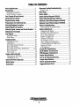
TABLE OF CONTENTS
Parts Identification ................................................2
Introductl"on ............................................................. 3
Warranty Procedures ......................................... 3
Serial Number Location .................................. .4
Fuel, Engine Oil and Coolant.. ............................5
Admiral Control Panel .........................................6
Captain Control Panel .........................................7
Preparations for Initial Start-Up ......................... 8
Starting/Stopping Procedure ...............................9
Engine Break-In Procedure ............................... l0
Warning Lights, Alarms and Circuit Breaker .... 11
Maintenance Schedule .................................... .12
Alternator Testing/Troubleshooting ..................25
Battery Care .................................................... 27
Glow Plugs .........................................................28
Starter Motor .....................................................29
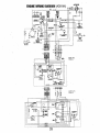
Engine Wiring Diagram (#39144) ......................31
Engine Wiring Schematic (#39144) ................... 32
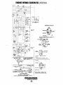
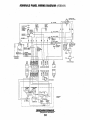
Admirals Panel Wiring Diagram (#36844) ........ .33
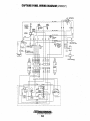
Captains Panel Wiring Diagram (#36467) ......... 34
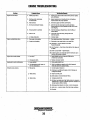
En9ine Troubleshooting .....................................35
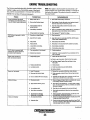
Control Panel Troubleshooting ...................... .37
Engine Adjustments ............................................ .38
Adjusting Idle Speed ........:d........................ ·.... 3388
FuellRun Shut-Off Solenol .......................... .
Fuel System ....................................................... 14
D'
nve Belt AdJ'ustment .................................. .39
E
' Compressl'on ...................................... .39
FueI/Water Filter ............................................. 14
ngme
Fuel Filters ...................................................... 14
'l'
ti' ng 0'1
1 Pressure ...................................... .. 40
Cooling System .................................................. 15
Oil Pressure Switch ....................................... .40
Changing Coolant.. ......................................... 16
Valve Clearance Adjustment ......................... .41
Thennostat ...................................................... 17
CylinderHead Bolt Tightening ..................... .41
Raw Water Intake Strainer.............................. 18
Injection Timing ............................................ .42
Raw Water Pump ............................................ 18
Fuel Injectors ,................................................ .43
Raw Water Pump Parts Breakdown ............ 18A
JS and BWTransmissions ................................. .44
Heat Exchanger .............................................. 11 9
Hurth HBW/ZF Transmissions ......: .................... .46
9
Zinc Anode ...................................................... '.. P'RM N
. T
""
51
" L b" t" 0"1
20'
,ewage ransmlsslons ............................ .
Engme u rica 109 I .................. ................ .....
"S
f" t"
54
. the
0'1
Engme peci Ica Ions .......................................
l F'lt
l er .................................. .20
Ch angmg.
Lay-up and Recommissioning .......................... .56
Changing the Oil ........................................... 20
Remote Oil Filter (Optional) ..............................21
Torque Specifications ...................................... .57
Water Heater .....................................................22
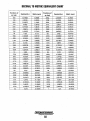
Metric Conversions Oata ...................................58
Tachometer ........................................................24
Suggested Spare Parts ......................................60
~es
...v- WESTERBEKE
Engines & Generators
1
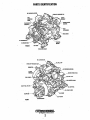
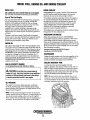
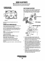
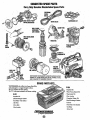
PARTS IDENTIFICATION
AIR INTAI!E/SIILENCIER,
.••U'~'" PRESSURE CAP
"iI~~:3r--- ENGINE SERIAL
~
OIL DRAIN HOSE
i
NUMBER
MOTOR
FRONT
DC ALTE~NATOR
FILL CAP
COOLANT PRESSURE
INTAKEJSILENCE~
___-.LIJ"~ UHIUN
PLUG
OIL FILL
FUEL PUNIP-,lbi~f:
.J ___,'RAW WATER PUMP
INLET FUEL FILTER
OIL DIPSTICK
DRAIN HOSE
SUMP
OIL FILTER
REAR
TRANSMISSION
~
WESTERSEKE
EngInes & Generators
2
INTRODUCTION
This WESTERBEKE Diesel Engine is a product of
WESTERBEKE's long years of experience and advanced
technology. We take great pride in the superior durability and
dependable performance of our engines and generators.
Thank you for selecting WESTERBEKE.
In order to get the full use and benefit from your generator it
is important that you operate and maintain it correctly. This
manual is designed to help you do this. Please, read this
manual carefully and observe all the safety precautions
throughout. Should your engine require servicing, contact
your nearest WESTERBEKE dealer for assistance.
This is your operators manual. A parts catalog is also
provided and a technical manual is available from your
WESTERBEKE dealer. If you are planning to install this
equipment contact your WESTERBEKE dealer for'
WESTERBEKE'S installation manual.
WARRANTY PROCEDURES
Your WESTERBEKE Warranty is included in a separate
folder. If, after 60 days of submitting the Warranty Registry
form you have not received a customer identification card
registering your warrauty, please contact the factory in
writing with model information, including the unit's serial
number and commission date.
Customer Identification Card
NOTES, CAUTIONS AND WARNINGS
IW WEStERSEKE
, Engines & Generators
Customer Identification
MR. ENGINE OWNER
MAIN STREET
HOMETOWN, USA
Model
Expires
PRODUCT SOFTWARE
Product software, (tech data, parts lists, manuals,
brochures and catalogs), provided from sources other than
WESTERBEKE are not within WESTERBEKE's control.
WESTERBEKE CANNOT BE RESPONSIBLE FOR THE
CONTENT OF SUCH SOFTWARE, MAKES NO WARRANTIES OR REPRESENTATIONS WITH RESPECT
THERETO, INCLUDING ACCURACY, TIMELINESS OR
COMPLETENESS THEREOF AND WILL IN NO EVENT
BE LIABLE FOR ANY TYPE OF DAMAGE OR INJURY
INCURRED IN CONNECTION WITH OR ARISING OUT
OF THE FURNISHING OR USE OF SUCH SOFTWARE.
WESTERBEKE customers should also keep in mind the
time span between printiogs of WESTERBEKE product
software and the unavoidable existence of earlier
WESTERBEKE manuals. In summation, product software
provided with WESTERBBKE products, whether from
WESTERBEKE or I1ther suppliers, must not and cannot
be relied upon exclusively as the definitive authority on
the respective product. It not "uly makes good sense
but is imperati~e that appropriate representatives of
WESTERBEKE or the supplier in question be consulted
to detennine the accuracy and currentness of the
product software being consulted by the customer.
As this manual takes you through the operating procedures,
maintenance schedules, and troubleshooting of your maline
engine, critical information will be highlight~d by NOTES,
CAUTIONS, and WARNINGS. An explanatIon follows:
NOTE: An operating procedure essential to note.
A CAUTION: Procedures, which if not strictly
observed, can result in the damage or destruction of
your engine.
Ser.#
A WARNING: Procedures, which if not properly
followed, can result in personal injury or loss of life.
'M7"
WESTERBEKE
Engines & Generators
3
INTRODUCTION
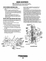
SERIAL NUMBER LOCATION
ORDERING PARTS
The engine's model and serial number are located on
a nameplate mounted on the side of the engine's water
jacketed exhaust manifold. The engine serial number is
also stamped into the engine block on the flat surface
out board of the injection pump. Take time to enter this
important information on the illustration of the namplate
below, as this will provide a quick reference when seeking
technical infOrmation and/or ordering parts.
Whenever replacement parts are needed, always provide the
engine model number and serial number as they appear on
the silver and black name plate located on the manifold. You
must provide us with this information so we may pro'perly
identify your engine. In addition, include a complete part
description and part number for each part needed (see the
separately furnished Parts List). Insist upon WESlERBEKE
packaged parts because will fit or generic parts are frequently
not made to the same specifications as original equipment.
iiiiijiiiiiiiiiii..
SPARES AND ACCESSORIES
Certain spares will be needed to support and maintain your
WESlERBEKE engine. Your local WESlERBEKE dealer
will assist you in preparing an inventory of spare parts. See
the SPARE PARTS page in this manual. For Engine
Accessories, see WESlERBEKE'S ACCESSORIES
brochure.
Fill in the' injo1711ation for y~ur reference. ~
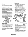
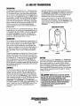
UNDERSTANDING THE QIESEL ENGINE
INSTALLATION MANUAL
The diesel engirie closely resembles the gasoline engine,
since the mechanism is essentially the same. The cylinders
arranged above a closed crankcase. The crankshaft is the
same general type as a gasoline engine, and the diesel engine
has the same types of valves, camshaft, pistons, connecting
rods and lubricating system.
Therefore, to a great extent, a diesel engine requires the
same preventive maintenance as a gasoline engine. The
most important factors are proper ventilation and proper
maintenance of the fuel, lubricating and cooling systems.
Fuel and lubricating filter elements must be replaced at the
time periods specified, and frequent checking for
contamination (water, sediment, etc.) in the fuel
system is also essential. Another important factor is the
consistent use of the same brand of high detergent diesel
lubrication oil desigoed specifically for diesel engines.
The diesel engine does differ from the gasoline engine,
however, in its method of handling and firing of fuel. The
carburetor and ignition systems are replaced by a single
component'- the fuel injection pump - which performs the
function of both.
Publication #43400 provides de1hlled information for
installing engine•. '
.
are
. PROTECTING YOUR INVESTMENT
Care at the factory during assembly and thorough testing
. have resulted in a WESlERBEKE engine capable of many
thousands of hours of dependable service. However the
manufacturer cannot control how or where the engine is
installed in the vessel or the manner in which the unit is
operated and serviced in the field. This is up to the
buyer/owner·operator.
NOTE: Six important steps to ensure 10llg engine life:
• Proper engine installation and alignment.
..• An efficient well.designed exhaust system that includes
an anti-siphon break to prevent water from entering the
engine.
• Changing the engine o{[ and oil filters every 100
operating hours.
. • Proper maintenance of all engine and generator
components according to the maintenance schedule in
this manual.
• Use clean, filtered dieselJueL
~Iii--DIIESI!L FUEL SPRAY
• Winterize your engine according to the "Lay.up and
Recommissioning" section in this manuaL
PRE·COMBUSTION CHJI,MBI:R~";:
EngInes & Generators
4
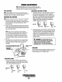
DIESEL FUEL, ENGINE OIL AND ENGINE COOLANT
DIESEL FUEL
ENGINE COOLANT
USE A DIESEL FUEL WITH A CETANE RATING OF #45 OR HIGHER.
(No. 2·D (SAE J313) diesel fuel according to ASTM D975}.
WESTERBEKE recommends a mixture of 50% antifreeze
and 50% distilled water. Distilled water is free from the
chemicals that can corrode internal engine surfaces.
The antifreeze performs double duty. It allows the engine to
run at proper temperatures by transferring heat away from
the engine to the coolant, and lubricates and protects the
Care Of The Fuel Supply
Use only clean diesel fuel! The clearance of the components
in your fuel injection pump is very critical; invisible dirt
particles which might pass through the filter can damage
these finely finished parts. It is important to buy clean fuel,
and keep it clean. The best fuel can be rendered
unsatisfactory by careless handling or improper storage
facilities. To assute that the fuel gping into the tank for your
engine's daily use is clean and pure, the following practice is
advisable:
Purchase a well-known brand of fuel.Install and regularly
service a good, visual-type fuel filter/water separator between
.the fuel tank and the engine. The Raycor 500 MA or 230
RMAM are good examples of such filters.
ENGINE OIL
Use a heavy duty engine oil with an API classification of CF,
CG-4, CH-4 or CIA. Change the engine oil and filter after an
initial 50 hours of break-in operation. Then follow the oil and
filter change intervals as specified in the MAINTENANCE
SCHEDULE in this manual. Westerbeke Corporation does
not approve or disapprove of the use of synthetic oils. If
synthetic oils are used, engine break-in must be performed
using conventional oil. Oil change intervals must be as in the
MAINTENANCE SCHEDULE, not extended because
synthetic oils are used.
cooling circuit from rust and corrosion. Look for a good
quality antifreeze that contains Supplemental Cooling
Additives (SCAs) that keep the antifreeze chemically
balanced, crucial to long term protection.
The distilled water and antifreeze should be premixed before
being poured into the cooling circuit.
PURCHASING ANTIFREEZE
Rather than preparing the mixture, WESTERBEKE
recommends buying the premixed antifreeze so that so that
when adding coolant the mixture will always be con·ect.
There are two common types of antifreeze, Ethylene Glycol
(green) and Propylene Glycol (red/purple), either can be used
but do not mix the two and if changing from one to another,
flush the engine thoroughly.
Premixed antifreeze for DIESEL Engines:
Specification #ASTM D53456.
MAINTENANCE
Change the engine coolant every five years regardless of the
number of operating hours as the chemical additives that
protect and lubricate the engine have a limited life.
COOLANT RECOVERY TANK
SAE OILVISCOSITY GRADES
A coolant recovery tank kit is supplied with each
engine or generator. The purpose of this recovery tank is to
allow for engine coolant expansion and contraction during
engine operation, without the loss of coolant and without
introducing air into the cooling system. This kit is provided .
and must be installed before operating the engine.
For all temperatures use SAE lOW-3D or l5W-40.
A
CAUTION: 00 not allow two or more brands of
engine oil to mix. Each brand contains its own a(lditives;
additives of different brands 1I0uid reactin the miXture
to produce properties harmful to your engine.
NOTE: This tank, with its short run of plastic hose, is best
located at or above the level of the engine's manifold, but it
can be located below the level of the engine's manifold if the
particular installation makes this necessary.
OIL PRESSURE
The engine's oil pressure, during operation, is indicated
by the oil pressure gauge on the instrument panel. During
normal operation, tl,e oil pressure will range between 35 and
65 psi 2.5 and 3.9 kg/cm').
NOTE: A newly started, cold engine can have an oil pressure
reading upwards of60 psi (4.2 kg/cm". A warmed engine can
have an oil pressure reading as lowas 25 psi (1.8 kg/cm".
These readings will vary depending upon the temperature of
the engine. the load placed on the engine, and the RPM's.
Engines & Generators
5
ADMIRAL CONTROL PANEL
DESCRIPTION
When the engine is shut down with the key switch turned off.
the water temperature gauge will continue to register the last
temperature reading indicated by the gauge before electrical
.power was turned off. 'The oil pressure gauge will fali to zero
when the key switch is turned off. 'The temperature gauge
. will once again register the engine's Ime temperature when
electrical power is restored to the gauge.
A separate alarm buzzer with harness is supplied with every
Admiral Panel. The installer is responsibla'for electrically connecting the buzzer to the four~pin connection on the engine's
electrical harness. 'The installer is also responsible for installing
the buzzer in a location where it will be dry and where it will
be audible to the operator should it sound while the engine is
running. 'The buzzer will sound when the ignition key is turned
on and should silence when the engine has started and the
engine's oil pressure rises above 15 psi (1.1 kglcrn'J.
This manually-operated control panel is equipped with a
KEY switch and RPM gauge with an ELAPSED TIME
meter which measures the engine's running time in hours and
in 1/10 hours. 'The panel also includes a WA1ER 1EMPERATURE gauge which indicates water temperature in degrees
Fahrenheit. an OIL PRESSURE gauge which measures the
engine's oil pressure in pounds per square inch. and a DC
control circuit VOLTAGE gauge which measures the system's voltage. All gauges are illuminated when the key
switch is turned on and remain illuminated while the engine
is in operation. The panel also contains two rubber-booted
pushbuttons. one for PREHEAT and one for START.
'OIL PRESSURE GAUGE; THIS GAUGE IS GRADU·
ATEO IN POUNDS PER SQUARE INCH (PSI) AND IS
ILLUMINATED WHILE THE KEY SWITCH IS TURNED
ON. THE ENGlNE'S NORMAL OPERATING OIL
PRESSURE RANGES BETWEEN 30 - 60 psi
(2.1 - 4.2 kglem').
WATER TEMPERATURE GAUGE; THIS GAUGE IS
GRADUATED IN DEGREES FAHRENHEIT AND IS
ILLUMINATED WHILE THE KEY SWITCH IS
TURNED ON. THE ENGINE'S NORMAL OPERATING
TEMPERATURE IS 170'-190' F(77' - 66·C).
RPM GAUGE; REGISTERS REVOLUTIONS
PER MINUTE OF THE
ENGINE AND CAN BE
RECALIBRATED FOR
ACCURACY FROM THE
REAR OFTHE PANEL.
--p;,..,_____
HOURMETER;
REGISTERS ELAPSED
TIME. AND SHOULD BE
USED AS A GUIDE FOR
THE MAINTENANCE
SCHEDULE.
PREHEAT
PRESSED. ENERGIZES THE
ALTERNATOR'S EXCITER. THE FUEL LIFT PUMP, THE
FUEL SDLENOIO ON THE INJECTION PUMP. ANO THE
ENGINE'S GLOW PLUGS. IT BYPASSES THE ENGINE'S
OIL PRESSURE ALARM SWITCH. IN ADOITION. THIS
BUTTON ENERGIZES. THE START BUTTON.
START BUTTON; WHEN PRESSED, ENERGIZES THE
STARTER'S SOLENOID WHICH CRANKS THE ENGINE.
THIS BUTTON WILL NOT OPERATE ELECTRICALLY
UNLESS THE PREHEAT BUTTON IS PRESSED AND HELD
AT THE SAME TIME.
__-KI:Y S'WITI~H; PROVIDES
POWER ONLY TO THE
INSTRUMENT PANEL
CLUSTER.
~
~
:
•
.
'
'/..,
]1.
.••••••••
DC VOLTMETER;
INDICATES THE AMOUNT THE
BATIERY IS BEING CHARGED.
!iHOULD SHOW 13V TO 14V.
AUTOMATIC ALARM SYSTEM
COOLANT TEMPERATURE ALARf,,; AN ALARM BUZZER HAS BEEN
SUPP LIED WITHTHEINSTRUMENT PANEL.IFTHE ENGINE'S
COOLANT
.
REACHES 210' F (99·C),.THIS SWITCH WllLCeOSE SDUNOING THE ALARM
WHICHWILlEMIT A CONTINUOUS SIGNAL.
OIL PRESSURE AI.ARM; AN Oil PRESSURE ALARM SWITCH IS
lOCATEOPFF THEENGiNE'S Oil GALLERY. THIS SWITCH MONITORS
t~E5E~~rp~~(g~!~.~S~~C~;)~~~~~~T~M~?~~~~E~~6~~~~~~\fteLL
ALARM. IN THIS EVENT. THE ALARM WILL EMIT A PULSATING SIGNAL
~
WESTERBEKE
Engines & Generators
6
CAPTAIN CONTROL PANEL
DESCRIPTION·
The panel also includes an alann buzzer for low OIL
PRESSURE or high COOLANT 1EMPERATURE. The
RPM gauge is illuminated when the KEY switch js turned on
and reniains illuminated while the engine is in openition.
This manually-operated control panel is equipped with a
KEY switch, an RPM gauge, PREHEKf and START buttons, an INSTRUMENT TEST button and three indicator
lamps, one for AL1ERNATOR DISCHARGE, one for low
OIL PRESSURE, and one for high ENGINE COOLANT
TEMPERATURE.
ALARM: THE ALARM WILL SOUND IFTHE ENGINE'S OIL PRESSURE FALLS
BELOW 5-10 psi (0.4-0.7 kg/em'). IN THIS EVENT, THEALliRM WILL EMIT A
PULSATING SIGNAL. THE ALARM WILL ALSO SOUND IF THE COOLANT
TEMPERATURE IN THE FRESHWATER COOLING CIRCUIT RISES TO·
210'F (99'C). IN THIS EVENT,THE ALARM WILL EMIT A CONTINUOUS SIGNAL.
NOTE: THE ALARM WILL SOUND WHEN THE KEY SWITCH IS TURNED ON. THIS
SOUNDING IS NORMAL. ONCE THE ENGINE STARTS AND THE ENGINE'S OIL
PRESSURE REACHES 15 psi M~1 k'g/em~, THE ALARM WILL SILENCE
RPM GAUGE: REGISTERS REVOLUTIONS
PER MINUTE OF THE ENGINE AND CAN BE
RECALIBRATED FOR ACCURACY FROM
THE REAR OFTHE PANEL
OIL PRESSURE
ALARM
TEST BUlTON: WHEN
PRESSED, TESTS THE
ALTERNATOR. THE OIL
PRESSURE, AND THE
COOLANTTEMPERATURE CONTROL CIRCUITS. WHEN PRESSED.
THE ALTERNATOR, THE
OIL PRESSURE, AND
THE WATER TEMPERATURE INDICATOR
LIGHTS ILLUMINATE IN
. ADDITION TO SOUND·
ING THE ALARM
BUZZER.
---~-- KEY SWITCH: PROVIDES
POWER ONLYTO THE
INSTRUMENT PANEL
CLUSTER.
LIGHT
START BUTTON: WHEN·PRESSEO, ENERGIZES THE
STARTER'S SOLENO,ID WHICH CRANKS THE ENGINE. THIS
BUlTON WILL NOT OPERATE ELECTRICALLY UNLESS THE
PREHEAT BUTTON IS PRESSED.AND HELD ATTHE SAME
TIME.
·"IIY'WESTERBEKE .
Engines··& Generators
7
BUTTON: WHEN PRESSED, ENERGIZES THE
.
ALTERNATOR'S EXCITER, THE FUEL LIFT PUMP, THE FUEL .
SOLENOID ON THE INJECTION PUMP, AND THE ENGINE'S
GLOW PLUGS, AND BYPASSES THE ENGINE'S OIL PRESSURE ALARM SWITCH. IN ADDITION, THIS BUTTON ENERGIZES THE START BUTTON.
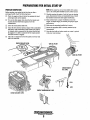
PREPARATIONS FOR INITIAL START-UP
PRESTART INSPECTION
NOTE: If the engine has not yet been filled with coolant,
Before starting your engine for the first time or after a
prolonged layoff, check the following items:
o Check the engine oilleve!. Add oil to maintain the level
at the high mark on the dipstick.
OThman the fuel supply, then check the fuel supply and
examine the fuel filter/water separator bowl for
contaminants.
Check the transmission fluid leve!.
o Check the DC electrical system. Inspect wire connections
and battery cable connections. Make certain the positive
(+) battery cable is connected to the starter solenoid and
the negative (-) cable is connected to the engine ground
stud (this location is tagged).
Check the coolant level in both the plastic recovery tank
and at the manifold.
refer to the COOLING SYSTEM section of this manual.
o
D Visually examine the engine. Look for loose or missing
parts, disconnected wires, and unattached hoses. Check
the threaded connections and engine attachment~.
D Make certain there is proper ventilation around the
engine. An ample supply is necessary for proper engine
perfonnance.
D Make sure the mounting installation is secure.
D Ensure the propeller shaft is securely attached to the
transmission.
D .Open the thru-hull and make certain raw water is primed
to the raw'water strainer.
o
TOP 'OIL FILTER
CHECK ENGINE
OIL LEVEL
,
.I.
.
CHECK TRANSMISSION FLUIO.
CHECK COOLANT LEVEL
~
WESTERBEKE
Engines & Generators
8
LOW
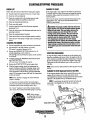
STARTING/STOPPING PROCEDURE
CHECKLIST
FAILURE TO START
Follow this check list each day before starting your engine.
If the engine fails to start when the start button is pressed for
D Visually inspect the engine for fuel, oil, or water leaks.
5 seconds, wait for at least 30 seconds and repeat the starting
procedure. Make certain the transmission control is in the
neutral position ..
Never run the starter motor for more than 30 seconds. If the
engine fails to start. refer to the TROUBLESHOOTING·
CHART in this manual.
D Check the oil level (dipstick).
D Check the coolant level in the coolant recovery tank.
D
D
D
D
D
D
D
Periodically check the manifold coolant level.
Check the transmission fluid level.
Check your fuel supply.
Look for clean fuel in the fuel filterlwater separator
transparent bowl.
Check for loose wires at the alternator and make sure its
mounting is secure.
Check the starting batteries (weekly).
Check drive belts for wear and proper tension (weekly).
Check the raw water pump to make sure its mounting is
secure.
A CAUTION: Prolonged cranking intervals without the
engine starting can result in the engine exhaust system
filling with raw water. This may happen because the
pump is pumping raw water through the raw water
cooling system during cranking. This raw water can
enter the engine's cylinders by way of the exhaust
manifold once the exhaust system fills. Prevent this
from happening by closing the raw water supply
through-hull shut-off; draining the exhaust muffler, and
correcting.the cause of the ellcessive engine cranking.
Engine damage resulting from raw water entry is not a
warrantable issue; the owner/operator should keep this
STARTING THE ENGINE
1. Put the transmission in neutral and advance the throttle.
2. Tum the· KEY to the ON position (2 o'ciock).
(The panel is energized, gauges are lit).
3. Depress the PREHEAT BUITON, hold for 5 to 15
seconds depending on how cold it is.
(The fuel lift pump is priming the engine and the preheat
is activated).
4. Continue pressing the PREHEAT BUTTON and press
the START BUTTON.
(The start motor is cranking the engine).
5. Release the START BUTTON as the engine starts.
6. With the engine running, check the instruments for
proper oil pressure and battery charging voltage. Also
check for overboatd discharge of exhaust water. The
water temperature will rise slowly until the thermostat
opens. Do not engage the gear shift until the temperature
is ciose to normal.
in mind_
STOPPING PROCEDURES
To stop the engine, bring the throttle to an idle position and
place the transmission in ·neutral. Allow the engine to idle for
a few moments to stabilize the engine temperature. Then pull
the shut-off teelknob out and allow the engine to stop fully.
Then push the shut-off tee!knob back in fully and shut-off
with key.
NOTE: Units with the Optional Electric Shut-Off, just turn off
the key.
FAILURE TO STOP (Optional Electric Shut-Off)
In the unusual situation that the ·key switch fails to tum the
engine off and it stays at a low idle, shut down can be
accomplished by manually working the shut off lever located
adjacent to the throttle lever by the injection pump.
NOTE: Never attempt to engage the starter while the
engine is running.
NOTE:' In such,cases the electric fuel sltut off soleuoid .
maym,edto be thu:aded into the block an additional
y. - V. turn.
It is important to closely monitor the panel gauges.
become aware of the normal engine readings and take
immediate action if these readings start to vary.
If a "smart" regulator is part of the charging system,
allow about 50 seconds for the RPM gauge to. activate.
NOTE: When starting:
A VQltage drop will occur
when the preheat·switch
is depressed.
ENGINE STOP LEVER'
Engi,.,e$ & Generator$
9
ENGINE BREAK-IN PROCEDURE
DESCRIPTION
Altliough your engine has experienced a minimum of one
hour of test operations at the factory to make sure accurate
assembly procedures were followed and that the engine operated properly, a break-in time is required. The service life of
your engine is dependent upon how the engine is operated
. and serviced during its initial 50 hours of use.
Breaking-in a new engine basically involves seating the piston rings to the cylinder walls. Excessive oil consumption
and smoky operation indicate that the cylinder walls are
scored, which is caused by overloading the engine during the
break-in period.
Your new engine requires approximately 50 hours of initial
conditioning operation to break in each moving part in order
to maximize the performance and service life of the engine.
Pelionn this conditioning carefully, keeping in mind the following:
1. Start the engine according to the STARTING PROCEDURE section. Run the engine at fast idle while checking
that all systems (raw water pump, oil pressure, battery
charging) are functioning.
2. Allow the engine to warm up (preferably by running at
fast idle) until the water temperature gauge moves into
the 130 - 140'F (55 - 60'C) range.
3. While using the vessel, run the engine at various engine
speeds for the first 25 hours. Avoid prolonged pedods of
idling.
4. Avoid rapid .acceleration, especially with a cold engine.
5. Use caution not to overload the engine. The presence of a
grey or black exhaust and the inability of the engine to
reach its full rated speed are signs ofan overload.
,6. During the next 25 hours, the engine may be operated at
vlUying engine speeds, with short runs at full rated rpm.
Avoid prolonged idling during this break-in pedod.
CHECKLIST
D Moniior the control panel gauges.
D . Check for leaks of fuel and engine oil.
D Check for abnonnal noise such as knocking, friction,
vibration and blow-back sounds.
D Confirm exhaust smoke:
When the engine is cold - white smoke.
When the engine is wann - almost smokeless.
When ihe engine is overloaded - some black smoke and soot.
NOTE: See the TRANSMISSION section of this manual for
break-in information on your transmission.
Engines & Generators
10
.
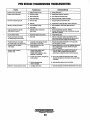
WARNING LIGHTS, ALARMS & CIRCUIT BREAKER
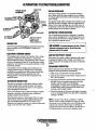
ALTERNATOR WARNINGS
COOLANT TEMPERATURE SWITCH
The Captain Control Panel indicates alternator low discharge
with a red warning light.
The Admiral Control Panel uses a voltmeter to monitor the
performance of the alternator.
A coolant temperature switch is located on the thermostat
housing; This switch will activate a continuous alarm if the
coolant's operating temperature reaches approximately ~J!Ff
(99'Cl.
THIS COOLANT TEMPERATURE SENDOR
IS ONLY AVAILABLE WITH THE AOMIRAL
COI!TRQ~ PANEL .
WATER (COOLANT) ..
TEMPERATURE· ' ,.
SENDER ,-
--"
-
.-
ENGINE CIRCUIT BREAKER
LOW OIL PRESSURE ALARM SWITCH
The DC hamess on the engine is protected by an engine
mounted manual reset circuit breaker (20 amps DC).
Excessive current draw or electrical overload anywhere in
the instrument panel wiring or engine wiring will cause the
breaker to trip. fu this event DC power to the electric fuel
pump will tenninate. As fuel is consumed and runs out, the
engine will slow and stop. If this breaker should trip, check
for the cause of high current draw and repair the problem.
Reset the breaker and re-start the engine.
A low oil pressure alarm switch is located on the engine
block. This switch's sensor monitors the engine's oil pressure. Should the engine's oil pressure fall to 5 - 10 psi
(0.4-0.7 kg/em'), this switch will activate a pulsating
alarm.
OIL PRESSURE SWITCH
Eng/nes & Gen,erstors
11
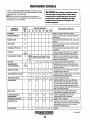
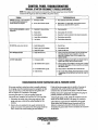
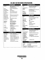
MAINTENANCE SCHEDULE
In order to use this Maintenance Schedule, it will be necessary
A WARNING: Never attempt to perform any service
to log your engine hours. Use your engine hourmeter or record
your engine hours by running time.
NOTE: Many of the following maintenance procedures are
simple but others are more difficult and may require the expert
knowledge of a service mechanic.
SCHEDULED
MAINTENANCE
CHECK
EACH
DAY
while the engine is running. Wear the proper safety
equipment such as goggles and gloves, and use the
correct tools for each job. Disconnect the battery
terminals when servicing any of the engine's DC
electrical equipment.
HOURS OF OPERATION
50
100
250 . 500
MAINTENANCE DESCRIPTION
750 1000 1250
Filter/Water Separator
D
D
Engine 011 Level
D
Oil level should indicate between MAX. and LOW on
dipstick.,.•
Coolant Level
D
Check at recovery tank; if empty, check at manifold.
Add coolant if neeii~d.
Transmission Fluid Level
D
Fluid level should indicate between MAX and LOW
on dipstick.
D
Inspect for proper tension (3/8" to 112" deflection)
and adjust if needed. Check belt edges for wear.
Fuel Supply
Drive Bells
Diesel No.2 rating of 45 cetane or higher.
Check for water and dirt in fuel (drain/replace filter
if necessary).
weekly
Visuallnspeclion of Engine
D
NOTE: Keep engine surface clean. Din and
Check for fuel, oil and water leaks. Inspect wiring
and electrical connections. Keep bolts & nuts tight.
Check for loose belt tension.
oil will inhibit the engine's ability to remain
cool.
Starting Batteries
(and House Batteries)
D
0
Fuel Filter
D
D
D
D
D
Change at 50 hours then every 250 hours.
Check electrolyte levels every 50 operating hours
and make sure connections are very tight. Clean off
excessive corrosion.
weekly
Engine 011 and Filter
D
D
D
D
D
D
D
Initial engine oil & filter change at 50 hours, then
change both every 100 hours.
Heat Exchanger Zinc Anode
0
D
D
D
D
D
D
Inspect zinc anode, replace if needed. Clear the heat .
exchanger end of zinc anode debris.
D
D
D
D
D
D
D
D
D
Change filter every 200 hours.
D
D
D
D
D
Hose should be hard & tight. Replace if soft or
spongy. Check and tighten all hose clamps.
Check for loose fittings, cotter pins, etc.
Lubricate with WD-40 or equivalent.
Filler/Water Separator
Exhaust System
0
0
Engine Hoses
Throttle Transmission
Shut-Off Cables
D
Adjust Engine Idle Speed
Raw Water Pump
D
Inlet Fuel Filter
D
D
D
D
D
D
D
D
D
D
D
Initial check at 50 hours, then every 250 hours.
Inspect for leaks. Check anti-siphon valve operation. Check the exhaust elbow for carbon and/or
corrosion buildup on inside passages; cl.ean and
replace as necessary. Check that alLconnections are
tight. Check castin'g integrity.
"
Adjustto 1000 -1200 rpm
Remove the pump cover and inspect the impeller,
gasket, cam and cover for wear. Check the bearings
and seals (the shaft can turn, but not wobble).
Lubricate when reassembling.
Replace.
(continued)
Engines & Generators
12
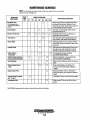
MAINTENANCE SCHEDULE
NOTE: Use the engine hourmeter gauge to log your engine hours of record your
engine hours by running time.
SCHEDULED
MAINTENANCE
CHECK
EACH
DAY
HOURS OF OPERATION
50
MAINTENANCE DESCRIPTION
100 250 500 750 1000 1250
Raw Water Pump
Remove the pump from the engine. Disassemble
and inspect all components, replacing all worn
components as needed. Inspect the drive gear slot
for wear. Replace drive gear as needed.
D
At 750 operating hours,
disassemble and inspect for
overhaul.
D
D
Drain, flush, and refill cooling system with the
appropriate antifreeze mix.
D
Periodically check the wiring Lonnections and
Inspect the fuel line connections.
Check and adjust Injection opening pressure and
spray condition. (see ENGINE ADJUSTMENTS).
D
D
'Preheat Circuit
D
D
Gheck.sqlenoid and motor for corrosion. Remove
and lubricate. Clean and lubricate the starter motor
pinion drive.'
~1
Check operation of preheat solenoid. Remove and
·clean glow plugs, check resistance (4-6 ohms).
Reinstall with anti-seize compound on threads.
'Engine Cylinder
Compression
D
D
Coolant System
Electric Fuel Lilt Pump
D
D
D
D
D
D
'Fuel Injectors
'Starter Motor
.
'Adjustthe Valve Clearances
Re-torque Cylinder Head Boils
D
D
'Heat Exchanger
D
'Water Injected Exhaust
Elbow
Engine Damper Plate.
Lubricate Panel Key Switch
with LDckeze"
Check compression pressure and timing
(see ENGINE ADJUSTMENTS).
D
Adjust Valve Clearances, re-torque cylinder head
bolts.(see ENGINE ADJUSTMENTS).
D
Remove, have professionally cleaned and pressure
tested.
D
D
Check casting Integrity every 500 hours of
operation. Clean internal passage. Replace as
needed.
Chattering at idle~ow rpm is an indication of
damper plate spring wear. Inspect and replace as
needed.
Lubricate at 50 hours, then at least once a season.
D
Initial change at 25 hours, then at least once a
season.
D
II
Transmission Fluid
'WESTERBEKE recommends this service be performed by an authorized mechanic.
Engines & Generators
13
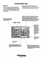
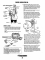
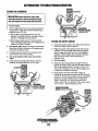
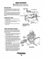
'FUEL SYSTEM
ENGINE FUEL FILTER
DIESEL FUEL
Periodically check the fuel connections and the bowl for
leakage. Replace the filter element after the first 50 hours
then follow the MAINTENANCE SCHEDULE.
USE A DIESEL FUEL WITH A CETANE RATING OF #45 OR HIGHER.
(No. 2-D (SAE J313) diesel fuel according to AStM D975}.
-Changing/cleaning the filter element
FUEL FItTERS
1. Shut off the fuel supply.
2. Unscrew the retainer ring that holds the filter bowl to the
housing and allow the bowl to coine away from the
housing,
The fuel injection pump and the fuel injectors are precisely
manufactnred and they must receive clean diesel fuel, free
from water and dirt. To ensure this flow of clean fuel, the fuel
must pass through at least two fuel filters, a fuel water
separator and the engine's spin-on fuel filter. Visually inspect,
clean, and change these filters according to the maintenance
schedule in this manual.
3. Remove and replace the filter element and clean the bowl.
4. Replace the sealing "0" ring and reassemble the bOWl
to the housing. Thread the retainer ring on carefully
,SO as not to cross 1bread. When retainer contacts the
"0" ring, tighten 1/4 - 112 turns by hand. Open the fuel,
ID!PPlY and run the engine to inspect for leaks.
FUEL WATER SEPARATOR
A primary fuel filter of the watef separating type must be
installed between the fuel tank and the engine to remove
water and other contami)lants from the fuel before they can
be, carried to the fuel 'system on the engine.
.
LIGHTLY WIPE
WITH CLEAN FUEL
WHEN INSTALLING
THE NEW FUEL
FILTER CARTRIDGE
The owner/operator is responsible for maldng certain the
fuel reaching the engine's injection equipment is free of
impurities. This process is accomplished hy installing and
maintaining a proper fuel
between the
fuel tank and the gerierator/engine.
a
10 micron (no'finer) filter be used.
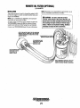
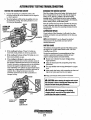
FUEL LIFT PUMP
TYPICAL
FUEL '
FILTER
INLET FUEL
FILTER
THE'D-RiNG n M""" 'it
ONLY NEEDS TO
,. REPLACfD IFfT
SIGNS OF AGING.
(OWNER IIlSTALLED)
FRESH FUEL
The fuel injection pump is the most important component
of the diesel engine, requiring the utmost caution in handling.
The fuel injection pump has been thoroughly bench-tested
and the owner/operator is cautioned -not to attempt to service
it. If it requires servicing, remove it and take it to an
authorized fuel injection pump service facility. Do not
attempt to disassembly and repair it.
The only adjustment the servicing mechanic should make to
the fuel injection pump is the adjustment for the engine idle
speed (see IDLE SPEED ADJUSTMENT under ENGINE
ADJUSTMENTS).
FUEL LIFT PUMP
Periodically check the fuel connections to and out me pump
and make sure that no leakage is present and that the fittings
are tight and secure. The DC ground connection at one of the
pump's mounting bolts sholjld be clean and. well secUred by
the_mounting boltto ensure proper pump o'petation. " '
When energized thrn the preheat circuit, the;fuellift pump will
purge air from the fuel system and provide a continuotis flow
of fuel as the engine is running.
'
INLET FUEL FILTER
,,1'0 ,nsure,cleanfuel-into the fuel pump, there is a small inline, fuel filter connected to the fuel lift pump elbow. This
filter should be replaced every 250 hours of operation or
once a season, which ever occurs first.
.
"IIY'
WESTERBEKE
~,?gines
& Generators
14
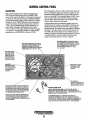
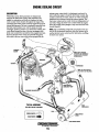
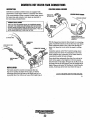
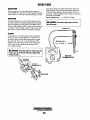
ENGINE COOLING CIRCUIT
exhaust system where finally it is discharged overboard. In
other words, the engine is cooled by fresh water coolant, this
coolant is cooled by raw water, and the raw water carries the
transferred heat overboard through the exhaust system. The .
fresh water coolant and raw water circuits are independent of
each other. Using only fresh water coolant wilhin the engine
allows the cooling water passages 10 slay Clean and free from
harmful deposits.
OEseRIPTION
Weslerbeke marine diesel generators are designed and
¢quipped for fresh water cooling. Heal produced in the
¢ngine by combustion and friction is transferred to fresh
water coolant which circulates throughout the engine. This
. ¢irculating fresh water coolant cools the engine block and its
internal meving parts. The heat is transferred externally from
the fresh water coolant to raw water by means of a heat
¢xchanger; similar in function to an automotive radiator. Raw
water flows through the tubes of the heat exchanger while
wesh water coolant flows around the tubes; engine heat trans~erred to the fresh water coolant is conducted through Ihe
tube walls to the raw water which is then pump~d into the
-""'.
''-........ ,
----
..
--.....:..
NOTE: Refer to ENGINE COOLANT paragraphs in this section for the recommended antifreeze and water mixture to be
used'as the fresh water coolant and for information on filling
the fresh water system.
----.'..
EXHAUST
NOTE: AN ANTI·SIPHON
VALVE MAY BE REQUIRED
TYPICAL ASSEMBLY
HEAT
EXCHANGER
COOLING CIRCUIT DIAGRAM
*
FRESH WATERy
RAW WATER
FRESH WATER
DRAIN
DRAIN
... WESTERBEICE
Engines & Generators
15
COOLING SYSTEM
FRESH WATER COOLlN.G I;I{lCUIT
Ftesh w:at~r coolant is pumped through the engine by a
'circulating pump, absorbing heat from the engine. The
coolant then passes through the .thermostat into the manifold,
to the heat exchanger where it is cooled and returned to the
engine block via the suction side of the circulating pump.
When the engine is started cold, external coolant flow is
prevented by the closed thermostat (although some coolant
flow is bypassed around the thermostat to prevent the exhaust
manifold from overheating). As the engine warms up, the
thermostat gradually opens, allowing full flow of the engine's
coolant to flow unrestricted to the external portion of the
cooling system .•
·NOTE: Periodically check the condition of the pressure cap.
Ensure thot the upper and lower rubber seals are in good
condition and check that the vacuum valve opens and closes
tightly. Carry a spare cap.
CHANGING COOLANT
ENGINE COOLANT
The engine's coolant must be changed according to the
MAINTENANCE SCHEDULE. If the coolant is allowed to
become contaminated, it can lead to overheating problems.
Drain the engine coolant by removing the block drain adjacent to the oil filter, remove the in-board drain plug on the
heat exchanger and ·remove the pressure cap from the water
jacketed exhaust manifold.
WESTERBEKE recommends a mixture of 50% antifreeze
and 50% distilled water. bistilled water is free from the
chemicals that can corrode internal engine surfaces.
The antifreeze performs a double duty. It allows the engine
to run at proper temperatures by transferring heat away from
the engine to the coolant and lubricates and protects the
cooting circuit from rust and corrosion. Look for a good
quality antifreeze that contains Supplemental Cooling
Additives (SCAs) that keep the antifreeze chemically balanced, crucial to long term protection.
BLOCK
. .COOL
DRAIN
NOTE: Lookfor the new environmentally friendly long lasting
antifreeze that is now available.
~ 4/)J~
. & ,.
\ (f(~~ ~?~
'i 1:;:::-
@'ii
The recommended 50/50 mixture will protect the engine
against the most extreme temperature. The antifreeze mixture
will also retard rust within the engine and add to the life of
the circulating pump impeller and seals.
A proper 50/50 mixture as recommeI!ded will protect the
engine coolant to temperatures of - 40'F.
1
0$ 'l~
.
. 0
~
Refillil1gthe.;~oolant
After closing the engine drains, pour clean, preri:rixed coolant
into the manifold, start the engine and run it at a slow idle.
Monitor the coolant in the manifold and add as needed. Fill
the manifold to the filler neck and when the coolant is
flowing, install the pressure cap.
Remove the cap on the coolant recovery tarik and fill with
coolant mix to halfway between LOW and MAX and replace
the cap. Run the engine and observe the coolant expansion
flow into the recovery tarik.
After checking for leaks, stop the engine and allow it to cool.
Coolant should draw back into the cooling system as the
engine cools down. Add coolant to the recovery tarik if
needed. Clean up any spilled coolant
A CAUTION: The engine "",ust be allowed to cool
Coolant Recovery Tank
The coolant recovery tarik allows for the expansion aJ!d contraction of the engines coolant during engine operation withoutintroducing air into the system. This recovery tarik is
provided with fresh water cooled models and with the fresh
water coolant conversion kit and must be installed before
operating the engine.
down before attempting these procedures. Not only is
the sudace of the engine hot but coolant temperatures
can be at 190'F.
A CAUTION: Proper cooling system maintenance is
.NOTE: This tank, with its short run ofplastic hose, is best
critical; a substantial number of engine failures can be
tracedbackto cooling lIystem corrosion.
located at or above the level of the engine's manifold.
ElJ.gJn_t!~ & Generators
16
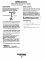
COOLING SYSTEM
THERMOSTAT
A thennosta~ located near the manifold at the' front of the
engine, controls the coolant temperature as the coolant
continuously flows through the closed cooling circirit. When
the engine is first started, the closed thennostat prevents
coolant from flowing (some coolant is by-passed t)rrough a
hole in the thermostat to prevent the exhaust manifold from
overheating). As the engine warms up, the thennostat
gradilally opens. The thennostat is accessible and can be
checked, cleaned, or replaced easily. Carry a spare thermostat
and gasket
. THERMOSTAT
'ASSEMBLY
A coolant recovery tank allows for engine coolant expansion
and contraction during engine operation, without any·significant loss of coolant and without introducing air into the cooling system.This· tank should be located at or above the
engine manifold level and should be easily accessible.
TO COOLANT
RECOVERY TANK
KEEP THE
COOLANT PASSAGE
CLEAR
FROM COOLANT
RECOVERY TANK
HOUSING
A CAUTION: The engine must be allowed to cool
Replacing the Thermostat
doWn' before attempting these procedures. Not only
is the surface of the engine hot but coolant
temperatures can be at 190' F.
Remove 'the cap screws and disassemble the thermostat
housing as shown. When instaJJingthe..ii:ew thermostat and
gasket, apply a thin coat of sealant on both sides of the
gasket before pressing it into place. Do not over-tighten the
cap screws.
Run the engine and check for normal temperatures and that
there are uo leaks at the thermostat housing.
Eng/nilS & Generators
17
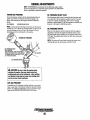
COOLING SYSTEM
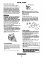
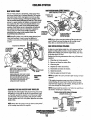
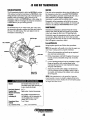
.. ·RAW-wATERJ'llMP(wu,Y"MODELsj
RAW WATER PUMp·
The raw water pump is a.,self-priming, rotary pump with a
non-ferrous housing and a Neoprene impeller. The impeller
has flexible blades which wipe against a curved cam plate .
within the impeller housing, producing the pumping action.
On no account should this pump be run dry. There should
always be a spare impeller and impeller cover gasket aboard
(an impeller kit); Raw water pump impeller failures occur
when lubricant (raw water) is not present during engine
operation. Such fat1ures are not warrantable, and operators
are cautioned to tnllke sure raw water flow is present at
start-up. The raw water pump should be inspected
peiipdjcally for broken or tom impeller blades. See
MAtNI'ENANCP; S9HEDULE.
.
SAME INSTRUCTIONS APPLY .
Impeller Kit
#034440
THE IMPELLER
SCREW WITH THE
, SLOT IN THe SHAFT
NOTE: Shoultr afailure occur with the pumps internal parts'
(seals and bearings), it may be more cost efficient to
NOTE: [{any ofthe vanes have broken off the impeller tliey
must be found to prevent blockage in the cooling circuit
They often can be founil iii; the heat exchanger.
p~rc1ulse a new pump and rebuild the original pump as
. a spare.
ImpellerKit #048500
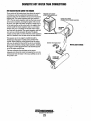
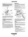
RAW WATER INTAKE STRAINER
FITTING SCREW
SLIDES INTO
SHAFT SLOT
•IMPELLER
INSPECTION: CHECK AT THE
, EACH BLADE BY BENOiNG VIGOROUSLY.
. REPLACE THE IMPELLER IF THERE
ARE ANY CRACKS•.
WHEN INSTALLING: TAKE CARE TO AUGN
THE IMPELLER KEYWAY WITH THE SHAFT
KEY. FOLD THE IMPELLER BLAOESIN
EITHER DIRECTION (THEY WILL TURN IN
THE CORRECT POSITION WHEN THE
IMPELLER STARTS TO ROTATE).
.'0"
.. :.;.
,~:--,
A cleao raw water intrus:e:strainer is a vital component of the
engine's cooling sysfum. Include a visual inspection of this ,
strainer when nuiking your pedodic engine check. The water
in the glass should be clear.
Perform the following maintenance after every 100 h6.urs' of
operation:
1. Close the raW water Beacoelt..
2. Remove aod clean the strainer filtet
3. Clean tile glass .
4. Replace the washer if necessary.
5. Reassemble aod install the strainer.
6. Open the seacock.
7. ,Roo the engine and check for leaks,
ni,'"
NOTE: Also follow the above procedure after having rnll hard
ag1'rJund.
RAW WATER
PUMP'
#048080·
If the engine temperature gauge ever shows a higher than
normal reading, the cause may be that silt,leaves or grass
may have been caught up ill the strainer, slOWing the flow of
raw water through the. cooling system.
NOTE: Always install the strainer at or belo~ the waterline so
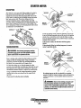
CHANGING THE RAW WATER PUMP IMPELLER
the strainer will always be self-printing.
Close the raw water intake valve. Remove the pump cover
and gasket or O-ring with the aid of tWo screwdrivers or pliers. Carefully pry/pull the impeller out of the pump. Lightly
coat the inside of the pump housing with glycerine, InstaU
the new impeller aod cover with gasket, open the raw water
intake valve.
TYPICAL RAW WATER INTAKE STRAINER
(OWNER INSTALLED) .
INCOMING
FI~TER
NOTE: Never allow the pump to rnn dry. Even a short period ,
of dry rnnning may destroy the impeller.
SEACOCK;,..·"""''''''''''
~WESTERBEKE
Engl!J~-4~en!Jrators
18
INSPECT AND
GLEAN EVERY
100HOURS
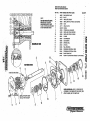
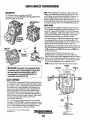
REPAIR PARTS ARE AVAILABLE
FROM YOUR WESTERBEKE DEALER
KEY NO.
NOTE
THE PUMP-REPAIR KIT (49000)
INCLUDES ALL THE USTED
CDMPQNENTS EXCEPT ITEMS
1 AND 7., THE KiT ALSO INCLUDES'
A PUMP MOUNTING GASKET.
ASSEMBLED VIEW
!l'
·a~"',.'
...• . • '
"~_c'-"l~". .' til
........ !II
1
2
3
4
5
'6
7
8
9
10
11
12
13
14 '
15
16'
17
18
PART NUMBER AND'PART NAME
48080
,49172
49170
48500
34458
49171
302575
48253
34463
48359
33041
33037
46662
48254 '
49169
34464,
33045
33044,
49000
37431
QUANITY '
RAW WJ!(fER PUMP'
1
SHAFT
1
IMPELLER COVER
1
IMPELLER KIT (O·RING & GLYCERIN) , I
CAM
1
WEAR PLATE
1
DOWEL
SPRING SEAL WASHER
1
IMPELLER COVER SCREW '
6
IMPELLER COVER O-RING
'1 '
O-RING
1
CAM WASHER
1,
CAM SCREW
l'
SPRING SEAL
1
LIP SEAL
l'
BALL BEARING
'2
RETAINING INTERNAL RING
l'
RETAINING EXTERNAL RING
l'
PUMP REPAIR KIT
1i
PUMP KIT (MOUNTING GASKET & FITTINGS) ,I'
1
••
CO ~ ",
-, . =,.
~,
:e
==
:t:!
;;I
:a
~
:s:
."
,-u
..... iQ ....
i':J'
'CD ~'.,
_
EXPLODED VIEW
'iI ,-,t'
Z
',S ~.
:CiJ',m·
~
ALlGNjSLOrJNtrJ OOWE~
00
a
-00
a
WHEN ASSEMBLING: APPLY A THIN COAT.QF
GLYCERIN TO THE (NSJOE OF THE COVER.' THIi
-COVER O-RlN6,ANO THE IMPELLER
'
PlffFITS INTO
THE SLOT IN THE'SHAFT
'IMYt:LLt:If
Engines & Generators
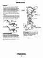
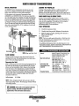
.COOLING SYSTEM
Zinc Anode #011885
A zinc anode, or pencil, is located in the raw water cooling
circuit within the heat exchanger. The purpose of having the .
zinc anode is to sacrifice them to electrolysis action takjng
place in the raw water cooling circuit, thereby reducing the
effects of electrolysis on other components of the system.
The condition of the zinc anode shonld be checked monthly
and the anode cleaned or replaced as required: Spare anodes
should be carried on board.
. If the zinc anodes need replacement, hold the hex boss into
which the zinc anode is threaded with a wrench while loos~
erung the anode with another wrench. 1his prevents· the hex
boss. frompossibly tearing off the exchanger shell. After
'
removing the iinc, note the condition of it. If the zinc is in
poor condition, thOte are probably a lot of zinc flakes within
the exchanger. Remove the end of the heat exchanger and
clean the inside of all zinc debris. Always have a spare heat
exchanger end gasket in case the present one becomes damaged when. ~emoving ~e end cover. Replace the gasket (refer
to your engIne model s heat exchanger end gasket part number), O-ring and cover, and install a new zinc anode.
NOTE: The threads of the zinc anodes lire pipe threads and
do .not require sealant. Sealant shoultlnot be used as it may
insulate the zinc from the metal of the heat exchanger housing preventing electrolysis action on the, zinc.
Heat Exchanger Service
NEW
REPLACE
REPLACE
After approximately 1000 hOl/rs of opera~on, remove, clean
and pressure test the engine's ~eat exchanger. (A local automotive radiator shop should be able to clean and test the heat
exchanger.).
.,
CLEAN AND
REUSE
ZINC ANODES
. NOTE: Operating in siliy and/or tropical waters may require
NOTE: Electrolysis action is the result of each particular
that a heat exchanger cleaning be performed' more often than
every 1000 hours.
installation and. vessel location; not that of the engine.
HEAT EXCHANGER
~
~
IRBlEED
PETCOCK
.~=.
ANTIFREEZE
CO'OlANT
DRAIN'
(PftCOCK OR HEX PLUI1;'
COVER
SECURING
OUT EVERY 'DRAIN
BOLT
100 HOURS
INSPECT
BOTH ENDS
CLEAN OUT DEBRis
TYPICAL ASSEMBLY
NOTE: When installing the heat exchanger end. covers. Be
sure that the end. cover seeUling,bolt.'s sealing O-ring is
installed. Failure to install miiiealingO.ring can result in
elld plate failure/sea water leakage.
Engilles & Gellerators
19
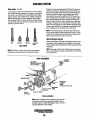
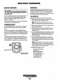
ENGINE LUBRICATING OIL
2. Replacing the Oil Filter. When removing the used oil
filter; you may find it helpful and cleaner to punch a hole
• in the upper and lower portion of the old filter to ~ain the
"il from it into a container before removing it. This helps
to lessen spillage. A small style automotive filter wrench
should be helpfijl in removing the old oil filter. •
TYPI.CAL LUBRICATION .O!A_GRAM
OIL PRESSURE' .
NOTE: Do not punch this hole without first loosening the
filter to make certain it can be removed!
OIL PRESSURE -~41
SWITCH
Place some paper towels and a plastic· bag aro~nd the
filter when unscrewing it to catch any oil left in the filter.
(Oil or any other fluid on the engine reduces the engine's
cooling ability. Please keep your engine clean.) Inspect the
old oil filter as. it is removed to make sure that the rubber
sealing gasket carne off with the old oil filter. If this
rupber sealing gasket remains sealed against the engine
block, g~ntly remove it. .
OIL FILTER,...---
PRESS~RE'-.....fi~~
OIL
RELIEF VALVE.'
OIL
OIL DRA.IN-~"-'
SCREEN
ENGINE OIL CHANGE
1. Draining the Oil Sump. Discharge the used oil through
the sump drain hose (attached to the front of the engine)
while the engine is warm. Drain the used oil complerely,
replace the hose in its bracket, and replace the end'cap
securely.
OIL FILTER
NOTE: Thread size for the lube oil drain hose capped end
#036918
is 114NPT.
When installing the new oil filter element, wipe the filter
gasket's sealing surface on the engine block free of oil and
apply a thin coat of clean engine oil to the rubber gasket'
on the new oil filter. Screw the filter onto the threaded oil
filter nipple, and then tighten the filter finnly by hand.
USINGAN~~r:::::~:::)~'i!~;~ge
TO DRAIN THE OIL OR PUMP
OIL UP THRU THE HOSE.
REMOVE
NOTE: Generic filters are not recommended, as the·
material standards or diameters of important items on .
generic parts might be entirely differentfram genuine
parts. Immediately after an ailfilter change andailfil~
run the engine to make suit! the oil pressure is normal and
that there are no oil leaks around
the new oil
,
, filter. .
. FOR EX1ENSION
NPT
.
A WARNING: Used engll1fl 011 contains harmful
contaminants. Avoid prolonged skin contact. Clean skin
and nails thoroughly using soap and water. LI/under or
discard Clothing or rags containing used oil. Discard
used oil properly.
3. Filling the Oil Sump. Add new oil through the oil filler
cap on the top of the engine. After refilling, run the
engine for a few moments while checking the oil
pressure. Make sure there is no leakage around the new
oil filter or from the oil drain system, and stop the engine.
Theu check the quantity' of oil with the lube oil dipstick.
Fill to, but not over the high mark on the dipstick, should
the engine require additional oil.
Englnes,,& (lenerators
20
REMOTE OIL FILTER (OPTIONAL)
.
PN# 040078
INSTALLATION
This popular accessory ·is used to reloc~te the engine's oil fil-
NOTE: Westerbeke is not responsiblefor engine failure due to
incorrect installation of the Remote ail Filter. . ,
ter from the engine to a more convenient location such as an
engine room bulkhead.
.
NOTE: Refer to ENGINE OIL CHANGE in this manual for
instructions on removing the oil jilter.
To install, simply remove the engine oil filter and thread on
WESTERBEKE's remote oil filter kit as shown. Always
install this kit with the oil filter facing down as illustrated.
Contact your WESTERBEKE dealer for more infonnation.
APPLY ATHIN COAT OF CLEAN OIL TO THE O·RING WHEN
INSTALLING THIS KIT. THREAD THE KIT ON, THEN HAND
TIGHTEN AN ADDITIONAL 3/4 TURN AFTER THE O·RING
CONTACTS THE BASE.
.
A CAUTION: It Is vital to install the oillin~s
correctly. If the oil flows in the reverse direction, the
bY1lass. valve In the filter assembly Will prevent the oil
from reaching the engine causing an internal engine
failure. 'If there is no oil pressure reading, shutdown
imediatelyand check the hose cnnnections.
FASTEN SECURELY,IO AB~~:~IT:~1
(SCREWS ARE OWNER iii
THE IN CONNECTION HOSE
MUST ATTACH TO THE OUT
~_ _ iiCiO~MNNioEii'ECTI.DiOiN AT THE
'"
FILTER.
THE OUT CONNECTION
MUST ATTACH TO THE
CONNECTION ATTHE
REMOTE OIL FILTER.
,
,Engines & Generators
21
" APPLY, ATHIN COAT OF CLEAN OIL TO niE FILTER
GASKET WHEN INSTALLING. AFTER THE FILTER
, toNTACTS THE BASE, TIGHTEN IT AN ADDITIONAL
DOMESTIC HOT WATER TANK CONNECTIONS
PREVIOUS MODEL ENGINES
DESCRIPTION
Bothihe two mid three cylinder models are equipped with
connections to send engine coolant to a domestic water heater.
[fthe owner/operator wishes to connect a water heater, remove
the bypass hose and connect a water heater as described in
.
the instructions presented below.
REMOVE THE
BY-PASS HOSE' ,
,HEATER BELOW ENGINE
• CURRENT MODEt.ENGINES' '
SIMPLY CUT INTO THE EXISTING HOSE AT THe THERMOSTAT HOUSING
AND INSERT TWO CONNECTORS (PifRr #802391)"INto THE TWO PIECES
OF HOSE. COUPLE THE HOSES FROM THE WATER TANK TO THE OTHER
END OF THE CONNECTORS AND TIGHTEN THE HOSE CLAMPS. IT WILL NOT
MATTER WHICH HOSES RUN TO AND FROM THE TANK.
HEATER COILS BELOW
, PRESSURE CAP ON ENGINE
MANIFOLD
With the bypass hose re11]?ved, there remain two connecting
points A and B for hoses to run to and from the water heater.
These connections assure '" fiowofhot water through the
heater at all times but do not restrict the engine's cooling
water.
, Connection point A on the Flow Control housing should
connect to the lower of the two connections on the water
heater while the upper connection on the heater returns to
connection B, nearest the heat exchanger_
Hoses should rise continuously from their low point at the
heater to the engine so that trapped air will rise naturally
from the heater to the engine. If trapped air is able to rise to
the heater, then an air bleed petcock must be installed at the
higher fitring on the heater for bleeding air while filling llie
system. Avoid loops in the hose runs which will trap air.
CONNECTOR
INSTALLATION .
The heater should be mounted conveniently either in a
high or low position in relation to the engine, so ·that the
connecting hoses from the heater to the engine can run in a
reasonably direct line without any loops which might trap air.
-
(CONT.) HEATER ABOVE THE ENGINE ,
engines & Generators
22
DOMESTIC HOT WATER TANK CONNECTIONS
HOT WATER HEATER ABOVE THE ENGINE
If any portion of the heating circuit rises above the engine's
own pressure cap, the a pressurized (aluruinum) remote
expansion tank must be installed in the circuit to become the
highest point. The remote expansion tanks part number is
24177. Tee the remote expansion tank into the heater circuit .
at the heater connection, choosing the higher of the two for
the retum. Tee right at the heater and plumb a single line up
to the tanks location and the other back to the engine's flow
control. Install the remote expansion tank in a convenient
location such as in a sail locker so the fresh water coolant
level can easily be checked. The remote expansion ian!<: will
now serve as a check and system fill point. The plastic
coolant recovery tank is not used when the remote expansion
tank kit is installed, since this tank serves the same function.
PRESSURE CAP IS RATED
LOWER THAN MANIFOLD. CAP
HEATER COILS ABOVE
PHt:>OUlit CAP ON ENGINE MANIFOLD
The pressure cap on the engine's manifold should be
installed once the engine's cooling system is filled with
coolant. Finish filling the cooling system from the remote
taDk once the system is filled and is free of air and eXhibits
good coolant circulation. During engine operation, checking
the engine's coolant should be done at the remote tank and
not at the engine manifold cap.
The hose connection from the heater to the remote
expansion tank should be routed and supported so as to rise
continuously from the heater to the tank, enabling any air in .
the system to rise.
.
,
REMOVE THE BY-PASS HOSE
..
.. ~.
~
ENGINE HEAT
. Englnes.& Generators
23
HEATER ABOVE ENGINE .....
TACHOMETER
TACHOMETER/HOUR METER
The tachometerlhour meter used in propulsion engine instrument panels contains two separate electrical circuits with a
common ground. One circuit operates the hour meter and the
other the tachometer. The hour meter circuit operates on 12
volts alternator charging voltage supplied to the (+) terminal
on the back of the instrument.
The tachometer circuit operates on AC voltage 6-8 volts, fed
from ~ne of the diodes in the alternator and supplied to the
tachometer input terminal while the engine is mnning, and
the alternator producing battery charging voltage 13.0-14.8
volts DC.
The following are procedures to follow when troubleshooting
a fault in either of the two circuits in a tachometerlhour
meter.
NOTE: Current model tachometers use a coarse adjustment'
dial to set the tachometer to the crankshaft pulley rpms. The
calibrating screw is then usedior fine tuning.
COARSE
ADJUSTMENT
Hour meter Inoperative
Check for the proper DC voltage between (+) and (-)
tenninals.
1. Voltage present - meter is defective - repair or replace.
2. Voltage not present - trace (+) and (-) e1ectlical connections for fault. (Jump 12 volts DC to meter (+)
terminal to verify the operation.)
Tachometer Inoperative
Check for the proper AC voltage between tachometer input
terminal and (-) terminal with the engine mnning.
1. Voltage present - attempt adjusting meter through calibration access hole. No results, repair or replace meter.
2. AC voltage not present - check for proper alternator DC
output voltage.
3. Check for AC voltage at tach terminal on alternator to
ground.
4. Check electrical connections from tachometer input terminal to alternator connection.
Tachometer Sticking
1. Check for proper AC voltage between "tach inp."
terminal and (-) terminal.
2. Check for good ground connection between meter (-)
terminal and alternator.
3. Check that alternator is well grounded to engine block at
alternator pivot bolt.
TACHOMETER CHECK (New Installation)
NOTE: In a new installation having new instrument panels,
the tachometer may not always be correctly calibrated to the
engine's rpm. This calibration should be checked in all new
installations.
1. Warm up the engine to normal operating temperature.
Remove any specks on the crankshaft pulley with a clean
cloth and place a piece of suitable reflecting tape on the
pulley to facilitate use of a photoelectric type tachometer.
2. Start and idle the engine.
3. Aim the light of the tachometer onto the reflecting tape to
confirm the engine speed. Check the instrument panel
tachometer reading. Adjust the tachometer in the panel by
using the instmment coarse adjustment to calibrate the
instrument reading to the closest R.P.M. that the photo tach
is showing. Then use the fine calibration adjustment to
bring the instrument to the exact rt:ading as the photo tach,
4. Set the tachometer to the idle speed (the engine idle speed
has been factory adjusted and the idle screws and high
speed screws have been locked in place).
,
--
~~ ~
I
Tachometer Inaccurate
i
ca" With a hand-held tach on the frollt of the crankshaft
pulley retaining nut or with a strobe-type tach, read the
front crankshaft pulley rpm at idle.
b. Adjust the tachometer using a 5/64 or 2mm Allen wrench
through the CAL. (calibration) access hole in the rear of
the tachometer. Zero the tachometer arid then adjust it to
the rpm indicated by the strobe or hand tachometer.
(Verify the rpm at idle and high rpm and adjust the
tachometer as needed)
----~OIL P~15S,
~
;<t-.
,, .
",
'
'I
•- - - - - - -(US- - I- -~-
~ "
I
- -- - -
t
~mR
,,,,,,;~~
III Btl
<
.3.-.-
II. 9l~ID
.!!!...lli.@
~
I. ",\
K[T ''"
SWITt~
"
~G~UG[
~
0:
VDllM[l[~
11DRlO
-i!:l'Q7
,
,
~'"O
~ >OS
"
"
I!
IUR[D
~
II. ~
D
®
-------------------------Engines & Generators
24
ALTERNATORS- TESTINGJTROUBLESHOOTING
TYPICAL 50 AMP
ALTERNATOR
#10 ORANGE BB!":~
TO STARTER 81
VOLTAGE REGULATOR
The integra! voltage regulator is an electronic switching
device which senses the system voltage level and switches
the voltage applied to the field in order to maintain it proper
. system voltage.
The regulator design utilizes all-silicon semi conductors and
. thick~film assembly techniques. After the voltage has been
'~..j;EiiiniNi\L adjusted to the proper regulating valve, the entire circuit is
,
encapsulated to protect the circuit and the components from
possible damage due to handling or vibration.
"'...,.,.."'''
ALTERNATOR TROUBLESHOOTING
m PINKJBLUE'
TO R TERMINAL-
DESCRIPTION
Use this troubleshooting section to determine if a problem
exists with the charging circuit or with the alternator. If it is
determined that the alternateir or voltage regulator is faulty,
have a qualified technician check it.
g~~~I8 Tff~::'NG
. MANUALFOR ALL
. WIRING CONNECTIONS
A WARNING: Aworking alternator run~ hot. A failed
The following information applies to the standard alternators'
that are supplied with WESTERBEKE'S Engines_ and
Generators.
ELECTRICAL CHARGING CIRCUIT
The charging system consists of an alternator with a voltage
regulator, an engine DC wiring hamess, a mouuted DC
circuit breaker and a battery with connecting cables. Because
of the use of integrated circuits (IC's), the electronic voltage
regulator is very compact and is mounted internally or on the
back of the alternator.
It is desirable to test the charging system (alternator and
voltage regulator) using the wiring hamess and electrical
loads that are a permanent part of the system and will then
provide the technician with an operational test of the
charging system as well as the major components of the
electrical system.
ALTERNATOR. DESCRIPTION
The stator is connected to a three-phase, full-wave bridge
rectifier package which contains six diodes. The bridge
converts the AC generated in the stator to a DC output for
battery charging and accessories,
Power to the regulator and the field of the integral regulator
alternator is provided by the field diode (or diode trio)
package contained in the alternator.
These alternators produce a rated output of 50 or 51 amps.
rated output is achieved at approxiroately 6000 alternator
rpm at an ambient temperatnre of 75°P (23.S°C). The
alternators are designed to operate in an ambient temperatnre
range of _40° to 212°P (-40° to 100°C).
altemator can become very hot. 00 not touch the
altemator until If has cooled.
LOW BATTERY/FAULTY CIRCUIT
If the starter only moans or makes a clicking sound instead
of spinning the engine to life it is likely a low battery or a
faulty connection in the starting circuit and not an alternator
problem.
PRELIMINARY INSPECTION
Before starting the actnal alternator and voltage.regulator,
testing the following checks are recommended.
•
1. Make certain your alternator is securely mounted.
2. Check the drive belts for proper tension. Replace the belt
if it is worn or glazed.
3. Check that all tennlnals, connectors and plugs are clean
and tight. Loose or corroded connections cause high
resistance and this conld cause overcharging,
undercharging or damage to the charging system. Badly
corroded battery cables could prevent the battery from
reaching a fully charged condition.
4. Check the condition of the battery and charge if necessary.
A low or discharged battery may cause false or misleading ..
readings in the tests.
NOTE: An isolator with a diode, a solenoid, or a battery
selector switch is usually mounted in the circuit to isolate
the batteries so the starling battery is not discharged along
with the house batteries. If the isolator is charging the
starting battery but not the house battery, the alternator is
OK and the problem is in the battery charging circuit.
Engines & Generators
25
ALTERNATORS TESTING/TROUBLESHOOTING
TESTING THE ALTERNATOR
A
CAUTION: Before starting the engine make
certain that everyone Is clear of moving parts! Keep
away from sheaves and belts during test procedures.
'li~~~~
6
.",...~ .
1. Start the engine.
2. After the engine has run for a few minutes, measure the
starting battery voltage at the battery tenninals using a
multimeter set on DC volts.
a. If the voltage is increasing toward 14 volts, the
altemator is working; omit Steps 3 through 8 and go
directly to "Checking the Service Battery."
b. If the voltage remains around 12 volts, a problem
exists with either the altemator or the charging circuit;
continue with Steps 3 through 8.
3. Thrn 00' the ·engine. Inspect all wiring and connections.
Ensure that the battery terminals and the. engine ground
connections are tight and clean.
4. If a battery selector switch is in the charging circuit,
ensure that it is on the correct setting.
S. Thrn on the ignition switch, but do not start the
engine. .
6. Check the battery voltage. If the battery is in good
condition, the reading should be 12 to 13 volts.
,MEASURiNG
BATIERY VOLTAGE
'(lGN.ITION ON
TESTING THE OUTPUT CIRCUIT
1. Connect the positive probe to the output terminal Band
connect the negative probe to ground ..
2. Wiggle the engine wiring harness while observing the
vol!I)leter. The meter should indicate the appro~imate
.battery voltage, and should not vary. If no reading is
obtained, or if the reading varies, check the alternator
output circuit for loose or dirty connections or
damaged wiring.
3. Start the engine.
4. Repeat the same measurelhent, the negative probe to
ground, the positive probe to B with the engine running:
The voltage reading shouidbe between 13.5 and 14.5
volts. If your altemator is over or under-charging, have
it repaired at a reliable service shop.
S. If the previous test reads ani)' battery voltage at
terminal B, use the meter to measure the DC excitation
terminal. If 12 volts is not present at exciter terminal R,
inspect the wiriIlg for breaks and poor connections.
Jump 12 volts from a 12 volt source (such the
..
battery) and operate the alternator. If the voltage' output
is 13-14 volts, . then the alternator is OK.
is:
.MEASURING
;--:-,-/~q •BAITelIY VOLTAGE
TESTING THE OUTPUT
CIRCUIT ENGINE RUNNING
ENGINE RUNNING
EXCITER
'TERMINAL
"R
,.y'
.WESTERBEKE
Engi,;e~ &
Generators
26
(+)
'~,\
.
ALTERNATORS TESTING/TROUBLESHOOTING
TESTING THE EXCITATION CIRCUIT
CHECKING THE SERVICE BATTERY
Check the voltage of the service battery. lhis battery shOuld
have .voltage between 13 and 14 volts when the engine is
running. If not, there is a pro.b1em in the service battery
charging circuit. Troubleshoot.the service battery eharging
circuit ·by checking the wiring and connections, the solenoid,
isolator, battery switch, and the battery itself.
When the problem has been solved and before the alternator
. is back in operation, take the time to tighten· and clean the
terminal studs. Also clean the connecting terminals from the
wiring harness.
1. Connect the positive (+) multimeter probe to the
excit~tion terminal R on the alternator and the negative
(-) lead to ground.
2. Turn the battery switch to the on position and note
the multimeter reading. The reading should be 1.3 to
2.5 volts (see illustration).
TESTING THE
EXCiTATION
J~IRCUJT
ALTERNATOR REPAIR
(IGNITION UIVl'-~il
If tests indicate a failed alternator, it will need to be disas-
sembled and repaired. Any good alternator service shop can
do the job.
NIiTE: WESTERBEKE'S service Manual has detailed
instructions for the disa"sembly and repair of their
staridard alternators.
· BATTERY CARE
3. If the reading is hetween .75 and 1.1 volts, the
rotor field circuit probably is shorted or wpunded.
4. If the reading is between 6.0 and 7.0 volts, the rotor
field circuit probably is open.
.
5. If no reading is obtained, an open eXists in the
alternator-excitation lead or in the excitation circuit of
the regulator. Disconnect the lead from exe. terminal R.
Connect the'positive multimeter probe to the excitation
lead and the negative multimeter probe to ground.
If the multimeter now indicates an approximate battery
voltage, the voltage regulator is defective and must be
replaced. If no voltageJs indicated, check the
excitation circuit for loose or dirty connectlons or.
damaged wiring.
The minimum recommended capacity of the battery used in
· the engine's 12 volt DC control circuit is 600 - 900 C;old
Cranking Amps (CCA).
·Review the manufacturer's recommendations lind thel).
establish a systematic maintenance schedule for·yout
engine's starting batteries and house batteries.
• Mouitor your voltmeter for proper charging during
engine operation.
• Check the electrolyte level and specific gravity with a
hydrometer.
• Use ouly distilled water to bring electrolytes to a proper
level.
•. Make certain that battery cable connections are clean and
tight to the battery posts (and to your engine).
•
Keep your batteries clean and free of corrosion.
A CAUTION: Before starting the engine make certain
that everyone is clear of moving parts! Keep away from
sheaves and belts during test procedures.
A CAUTION: To avoid damage to the battery
charging circuit, never shut off the engine battery
switch when the engine Is running!
(+)
TERMINAL R
. TESTING THE
EXCITATION
CIRCUIT
(IGNITION ON)
~
WESTERBEICE
Engines & Generators
27
GLOW PLUGS
Re-install the plugs in the engine and test them again. The
plugs should get very hot (at the terminal end) within 20. to
25 seconds. If the plugs don't heat up quiCkly, check for a
short circuit. When reinstalling the glow plugs, use anti-seize
compound on the tlrreads.
DESCRIPTION
The glow plugs are wired through the preheat solenoid.
When PREHEAT is pressed at the control panel this solenoid
should "click" on and the glow plug should begin to get hot.
Glow Plug Tightening Torque
INSPECTION
To inspect the plug, remove the electrical terminal connections, then unscrew or unclamp each plug from the cylinder
head. Thoroughly clean each plug's tip and tlrreads with a
soft brush and cleaning solution to remove all the carbon and
oil deposits. While cleaning, examine the tip for wear and
burn erosion; if it has eroded too m\lch, replace the plug.
7 -11 Ib-ff (1.0 -1.5 kg-m) ,
A WARNING: 00 not keep a glow plug on for more
than 30 seconds
TERMINAL .....____
TESTING
An accurate way to test glow plugs is with an ohmmeter.
Touch one prod to the glow plug's wire connection, and
the other to the body of the glow plug, as shown. A good
glow plug will. have a 1.0.- to 1.5-ohm resistance. This
method can be used with the plug in or out of the .engine.
You can also use an ammeter to test the power drain
(8 to 9 amps per plug).
Tightening tOl'flue:
(1.0 -1.5 m-kg (7· IIft-lb)
A WARNING: These plOW plugs will become very hot
to the touc". Be carefurnot til bum,yourJingers When
testing the plugs
. , . '. .
GLOW PLUG
THE OHMMETER TEST
GLOW PLUG
...>'..-l-~~
Engines & Generators .
28
STARTER MOTOR
DESCRIPTION
The starter is a new type, small, light-weight and is called a
high-speed internal-reduction starter. The pinion shafris
separate from the motor shaft; the pinion ~lides only on the
pinion shaft. A rednction gear is installed between the motor
shaft and a pinion shaft. The pinion sliding part is not
exposed outside the starter so that the pinion may slide
smoothly without becoming fouled with dust and grease. The
motor shaft is supported at both ends on ball bearings. The
lever mechanism, switch and overrunning clutch inner circuit
are identical to conventional ones.
TERMINALS-""-~
...,.,.....
[r~---(M) TERMINAL
IGNITION
TERMINAL
SOLENOID
To test the ignition circuit, locate the ignition(s) terminal (it
is one of the small terminal studs and is wired to the ignition
circuit). Use a screwdriver, don't touch the blade, to jump
from that ignition terminal to the positive battery connection
terminal on the solenoid.
If the starter cranks, the fault lies with the ignition
'
circult.
If the solenoid clicks bnt nothing happens, the starter
motor is probably faulty.
MOTOR
TYPICAL
STARTER MOTOR
,
REFER TO THEW/RING
DIAGRAM IN THIS MANUAL
TROUBLESHOOTING
A WARNING: The following emergency starting
SOLENOID
~
procedures must not be used with gasoline engines.
Sparks could cause an explosion and fire.
'AI''h'"--_(+) POSITiVE
Prior to testing, make certain the ships batteries are at full
charge and that the starting system wiring connections
(terminals) are clean and tight. Pay particular attention to
the 'ground wire connections on the engine block.
To check the wiring, try Cfl",c'dng the starter for a few
seconds, never more than 10 ,seconds at a time, then run your
hand along the wires and terminals looking for warm spots
that indicate resistance, Repair or replace any trouble spots,
Using a multimeter, test the voltage between the positive
terminal stud on the start solenoid and the engine block
(ground).,
If you read 12 volts, the starter is faulty.
'TERMINAL
. r~--(M) TERMINAL
IGNITION
, TERMINAL
~
If nothing hapF"ns at all, the solenoid is not getting
cnrrent.. Check the battery isolation switch and inspect the
wiring connections. it is also possible that the solenoid is
defective,
.
A WARNING: There will be arching and sparks will
fly. when jumping terminals. Be certain the engine
space Is free of potentially BJi#lloslve fumes, especially
gasoline, and tirat there are NO flammable solvents or
materials stored nearby.
-..v WESTERBEKE
Engines & Generators
29
STARTER MOTOR
EMERGENCY START
,A WARNING: When performIng these procedures,
Corrosion to the starter brushes and/or the solenoid contacts
can cause the spcradic problem of the engine starting one
time bul'not another. If corrosion is the problem, the starter
will Iieed to be rebuilt.
'
It is however, sometimes possible to get started by taping the
starter ligbtly with a small hammer.
With the battery switch off and no ignition,. tap lightly on the
starter/solenoid casing as shown, then try to start the engine.
position yourself safely away from the moving parts of
the engine in case the engine starts-up. Also warn
other crew members of the danger.
CAREFULLY NOT TO HIT
~
FITTINGS OR WIRE CONNECTIONS
\
~Ii{}_;:----(M)
~"
TERMINAL
TAP LIGHTLY WHERE
\ . INDICATED
IGNITION
TERMINAL
Test again by jumping the two large terminal studs, Hold the
screwdriver blade firmly between the studs. Do not allow the
screwdriver blade to touch the solenoid or starter casing, this
would cause a short.
A
If that fails, tum the battery switch on and have a crew
member tum the ignition on and off rapidly as you tap again
with the barrimer., This may loosen the brushes and allow
contact to start the engine. When you reach a repair facility,
the starter will need to be repaired.
WARNING: There will be arching as the full
starting current should be flowing thru the blade of
the screwdriver.
If the starter spins, the solenoid is faulty.
If the starter fails to spin, the motor is probably faulty.
If no arching occurred, tbere is no jnice reaching the
solenoid.
SERVICE
WESTERBEKE uses a standard starter motor which can be
serviced or rebuilt at any starter motor automotive service
center,
If replacing the st8rtef motor, make certain the new motor is
certified for marine use. Automotive starters do not meet
USCG standards. If in doubt, contact your WESTERBEKE
dealer.
NOTE: Sta1ter motors are either inertia type or pre~engaged.
In the pre-engaged model, the solenoid also moves an arm
that engages the starter motor to the flywheel of the engine.
using a screwdriver to bypass the solenoid on such 11. starter
will run the nwtor wiihout engaging the flywheel.. Thm the
stalter switch on to provide power to the solenoid. Hopefully
it will create enough magneticfieldfor the ann to nwve even
though the contacts inside the solenoid are bad.
~
TO REMOVE FOR SERVICE
1. Disconnect the negative battery cable.
2. If 'necessary, remove any components to gain full access
. to the starter motor.
3. Label and disconnect the wiring from the starter. (Do not
allow wires to touch, tape over the terminals).
- 4. Remove the starter mounting bolts.
5. Remove the starter from the engine. In some cases the
starter will have to be turned to a different angle to clear
obstructions,
WESTERBEKE
Engines & Generators
30
ENGINE WIRING DIAGRAM (#39144)
r---I
:~ :
It::
I
.
I
-
~
12 VDC
=-
>AIill:(
,,~
"~
"
ADMIRAL
PANEL
,,"U,,
IUZIU
r-=-:~::::-:-=-'J
___'-==, ___ '___ _
I
'- - - -
- -
- --
'-'="----'-----'--'-'_ - -
" f' \ "\ ~
I
_I
"
LU1l
;
CAPTAIN
PANEL
~~
,IH
---.J I
r
-
-
; "'-
I
,4~J
--c...s=
&T-'9
.-
0
ur=
.'" ,,/..'~ r
""'"")
(
J
I -~ -
" . .u
~~~
I
--- --
;,
ir.", \
~~L
~
--
~~
II", ...
I
... 'u
.I
- - --
-
•
•
31
- - -- _.
ENGINE WIRING SCHEMATIC (#39144)
s,,'l
I~ yO(;
•
-
n"nu
M
$Q~.
r -,
,, ,,
... _-----------
-':"-
------,
PUH[AT
r--.,
n,
SOl
--?J' ,
- --
'~CI'IIHVU
Al~UOI
;r
I[ ..
~~~~:
,
e.~.
r-:'--~---·-..'.'·.!:.I
I .!~ m",1
LifT 'UN'
., , •~
~.
'1
~
,
~
fUll
SMh...-7\
=1
J 'Pile ~liRN'ln,,9NI r
L
'-----------,
F-P
t
~-
~:•'"..
HII~UB!SHI
50 AHP ALI
ADM I RAL
PANEL
U;~!!~
~
114 1.11
,T
~
o~
.o[
S""T
~!:o
.........
AUU
--
UV5(
I
PRESTOLIT(\LEECEwMEVILLE 10 AMP. ALT.
610
$ UIIIH
~.
I
G"P
~
=-
.. OR
~"
L
,
-.. ..
.........
'UHIAT
SIITCH
'l'lrl"'f
.. .
ALT.
,~.
•,
STAU
$'. i
..
4'4 IllII
UCHOIItTU
"
n,
'"
,
".........
11£1
-----------~---------------,,'1
'1<1 . . 1-1,,,"
PH
.',
I
t
SOL.
t
sMi!~
•
I
run
I
,~r
,,U ~~IgJ""l:
1,
lWO
S~--e-'!!.[I!.!. -
!
t
I
P
"
·1
CAPTAIN
PANEL
"
"
0 ••.
O. DZ
LAW'
1.1.
LA••
"
..
n
114 LT. 8tU
II(
U
II
110 RED
•
."
SI AMP
0PRESTOI
'
ALTERNATOR
STANOARD ALTERNATOR ON TII£
~::BIjj, s:e,Hc ~~
I:!.
B211
0:.
I If
72
~
PIIiK
BRH
AMP
AI T
f..-------------------,14 BRN
114 GRA
.14 PINK
.14 LT .
•4
no
"~FT~"i~~ 1'..r:M~'I\W
I'
@
JJN I VERSA!
PRESTOI I Tf
OPT I DNA!
"U.
AYAlL",!" 9! IM( In
a
IIO~.
AI IERNAIORS
~EHU ~lT[RnTO.$
"0 rr In 11 !tU Jl
LU~.
us IJ
~
®
•
IUS n
001'
WESTERBEKE
.Engines & G.enerators
32
PROP!!I S ION
51 AMP
AI T
ADMIRALS PANELW.IRING DIAGRAM (#36844)
~
W'
JtJ::;Z o:'!Z'
~a:l%:3:
I§.::l ~5
~ ~~j;
S1
~
;[;19;
\';
~
z
;!!
,~
~
~
;;
~16
~
S216
',"
~
~
0
~
.~
;
",
0
iQ
"
1;
m
6 i 61
P20
~
I
--.--.~-! 1
:..;,•.)@~'"_ •• ~ ~~
I !
I \ ~\~
I
0
1·,4GRlI
;:.'
L_~_ _':-',,~~
'---'-----"'4:.--.
I
1
I
I
~
~
KEY SWITCH
~ ~\
c.;2
....;
.,..
\~!lLI':
J I~TCH
~
.:
TACHOMETER
I
START
PREHEAT
S~CH
VOL.TMETER
"'OIlLK.
I"
~
!
,"o
e
_____________
_
_l
_"
_!
J
~~
~
WESTERBEKE
Engines. & Generators
33
APMIRAL
PANEL
CAPTAINS PANEL WIRING DIAGRAM (#36467)
.---f-"~---...,
1
I
I
I
WATER
TEM".
G!.OwPLuGS
I
SWITCH
11",4,Q011;.
I
otllf.II!)IIIG 011
IlUNalA 01
Cll.llIOEIiSl
~
4
I
I
"'fG T.II.U(
I
,.NEHEt.T
;1-\
SOI..EN')IO
.,. T. !ll.IIE
"
___
I
SWITCH
_ --mL !U.f.~E'tIUSED c<
,
': J
I
PRESSURE
SENDEP.
,.
fO""'ON"I. ,..ITM
·"STAU"E"!
o;AGIIOiDTO
""'NELl
[MG"ll
~CCM
\
I
"WE.S'
0"
1
1
~E
_____
-1__
,,-.J
I
~
'I'
:
-Jr,
_-=q
OIL
PRESSURE'
... '" I
FUEL 501.£N010
Il1S(O 0'1 SOf4( ... oott.~l
:.~i~
LIFT
PUMP
",:-:'OID TO
(II6'1I( BUltK
~
~"
. LATER MCl'DE1S
"Y. r;,-: i:._ f:.
\-. "C-
--
-
~~
\
~,
V
~0+
I
-
- j,
""'CHOo-l[T[
Enaines & Generato'rs
34
!
!
I
I
I
I
ENGINE TROUBLESHOOTING
The following troubleshooting table describes certain problems
relating to engine service, the probable causes of these problems, and the recommendations to overcome these problems,
NOTE: Fuel run/shut off solenoid (Optional).
Problem
No pan,1 indications; fu,lsol,nold
or fuel pump Is not working (key switch
is on and PREHEAT button Is depressed).
NOTE: The engine's electrical system is protected by a 20
ampere manual reset circuit breaker located all a bracket at
the back of the engille. The preheat solelloid is niounted on.
the same bracket.
Probable Cause
Verilicallon/Remedy
1. Battel)l switch not on.
1. Check switch andlor battel)l connections.
2. 20-amp ch'cult breaker tripped.
2. Reset breaker; breaker Irlps again, check preheat solenoid
circuit and check circuit for shorts to· ground.
3. 1O-amp breaker tripped on
3. Check the ~ollage both al and after the breaker on Ihe
preheat solenoid.
preheat solenoid
4. loose batlel)l connections.
n
4. Check (+) connection to starter solenoid and (-) connection to
engine ground stUd. Check battel)l cable connections.
5. Preheat solenoid not operating.
5. Check solenoid "s" terminal for voltage.
1. Connection to solenoid faulty.
1. Check connection.
2. Gear shift not in neutrel.
2. Gear shift must be In neulrel (see NEUTRAL SWITCH under
HURTH HSW TRANSMISSIONS).
3. Faulty switch.
3. Check switch wilh ohmmeter.
4. Faulty solen'oid.
4. Check that 12 volts are present at the solenoid connection.
5. loose battel)l connecllons.
5. Check battel)l connections.
6. low battel)l.
6. Check battel)l charge state.
START button 15 depressed; panel
indications OK; starter solenoid OK;
1. Poor connections to fuel solenoid.
1. Check connections.
fuel solenoid n~t functioning.
2. Defective fuel solenoid.
2. Check that 12 volts are present althe (+) connection on the
fuel run solenoid.
Engine cranks, but does not
1. Faulty fueling system.
1. Check that fuel valves are open.
START button is depressed, no starter
engagement. .
start. fuel solenoid energized.
1a. Check for air In fuel system. Bleed air from fuel system.
1b. Fuel filters clogged. Replace filters and bleed air from
fuel system.
2. Preheat solenoid faulty.
2. Check solenoid.
3. Swllch to combine house and start batteries.
3. Low battery power.
3a. Replace batteries.
Engine can't be stopped.
Battery runs down.
1. Faulty DC allernator.
2. Dlsconn.ct fuel shut-off cable.
1. Remove Exc. connection at alternator: repair alternator.
3. Fuel run solenoid will not de-en~rgize.
3. Manually shut the engine down using the shut off lever
adjacent to the throttle lever on the engine.
1. Oil pressure switch.
1. Observe if gauges and panel lights are aclivaled when .nglne
2. Check connection at shut-off lever. Pul11ever back to close
offlhe lu.1
. Is not running, Test the oil pressure switch:
2. High resistance leak to ground.
2. Check wirlng.lnsert.sensitiv, (0 - .25 amp) meter In battel)l
lines. (Do not start engine.) Remove connections and replace
after short is located.
3. Low resistance leak.
3. Check all wires for temperature rise to locate the fault.
4. Check cable connections at battery for loose connect10~S,
corrosion
4. Poor battety connectIons.
-
Battel)l not charging
5. DC alternator not charging
(tachometer notop,retlngl.
1. DC charge circuit faulty.
5. Check connections, check belt tens10n, test alternator. See
OC ELECTRICAL SYSTEM/ALTERNATOR.
2. Alternator IIrlve.
2. Check drive belt tension; alternator should turn freely. Check
for loose connections. Check output with Voltmeter. Ensure 12
volts are present at the Exc. terminal.
1. Pertorrn DC voltag. check of g.n.retor charging circuit. See
7iJsting the B,Uety Charging Circuit
.
(continued)
EI1g1nes & Generators
35
ENGINE JROQBLESHOOTING
Problem
Engine slows and stops.
Probable Cause
VerilicationJRemedy
1. Fuel lift pump failure.
2. Switches and/or wiring loose
or disconnected,
3. Fuel starvation.
4. 20 Amp circuit breaker tripping.
5. Exhaust system Is restricted.
Engine overheats/shuts down.
1. Fuellift pump should make a distinct ticking sound. Replace
pump with spare.
2. Inspect wiring for short circuits and loose connections.
Inspect switches for proper operation.
3. Check fuel supply, fuel valves, fuel lift pump.
4. Check for high DC amperage draw during operation.
Ensure breaker is not overly sansitiva to heat which would
causa tripping.
5. Check for blockage, collapsed hose, carbon buildup at
exhaust elbow.
6. Water In fuel.
6. Pump water from fuel tank(s); change filters and
bleed fuel system.
7. Air Intake obstruction.
7. Check air intake
1. Raw water not circulating.
1. Raw water pump failure. Check Impeller - replace.
2. Coolant not circulating.
2. Obstruction at raw water Intake or raw water filter.
2a. Thermostat - remove and test in hot water.
Replace thermostat.
2b. Loss of coolant - check hoses, hose clamps, drain plug, etc.
for leaks.
2c. Broken or ioose belts - tighten/replace.
2d. Air leak in system; run engine and open the pressure cap to
bleed air. Add coolant as needed.
Engine alarm sound pulsates.
Engine alarm sounds continuously.
Exhaust smoke problems
1. Loss of oil.
1. Check dipstick, look for oil leaks at oil filter and at
01\ drain hose connection.
2. Oil pressure switch.
2. Replace oil pressure switch.
1. Engine coolant.
2. High temperature switch opens at .
too Iowa tamperatura.
1. Check engine coolant level.
2. Check for satisfactory oparation with switch bypassed,
check with ohmmeter, replace if faulty.
1. Blue smoke.
1. Incorrect grade of angine oil.
la. Crankcase is overfilled with engine oil (oil is blowing out
through the axhaust).
2. Engine Is running cold.
2. Whita smoke.
2a. Faulty injector or Incorrect injector timing.
3. Improper grade offuel.
3. Black smoke.
3a. Fuel burn incomplete due to high back'pressure in exhaust or
insufficient air for proper combustion (check for restrictions in
exhaust system; check air intake).
3b. Improperly timed injectors or valves, or poor compression.
3c. Lack of air - check air Intake. Check for proper ventilation.
3d. Overload.
) Engines & Generators
36
CONTROL PANEL TROUBLESHOOTING
MANUAL STARTER DISCONNECT (TOGGLE SWITCHES)
NOTE: The engine contro(system is protected by a 20 amp manual reset circuit breaker
located on the engine as close as possible to the power source.
Probable Cause
Problem
Verilication/Remedy
PREHEAT depressed, no panel Indications
fuel solenoid, electric fuel pump and
preheat solenoid not energized.
1. Oil Pressure switch.
1. Check switches andlor battery connections.
2. 20 amp circuit breaker tripped.
2. Reset breaker. If it opens again, check preheat solenoid
circuit and run circuit for shorts to ground.
START SWITCH DEPRESSED, no starter
engagement.
1. Connection to solenoid faulty.
1. Check connection.
NO IGNITION, cranks, does not slart.
2. Faulty swilch.
2. Check switch with ohmmeter.
3.. Faulty solenoid.
3. Check that 12 yolts are present at the solenoid connection.
4. Loose battery connections.
5 Low battery.
4. Check battery conneotions.
5. Check battery charge state.
·1. Faulty fueling syslem.
1. Check for fuel.
2. Check for air In Ihe fuel system.
2. Allow system to bleed.
3. Faulty fuel lift pump.
3. Replace fuel Uft pump.
NOT CHARGING BATTERY
1. Faulty alternator drive.
1. Check Ihe d~ve belt and Its lension. Be sure the alternator
lurns freely. Check for loose connections. Check Ihe
output with a voftmeter. Ensure 12V are present at Ihe
regulator lerminal.
BATTERY RUNS DOWN
1. Oil pressure switch.
1. Observe jf the gauges and panel lights are activated when the
engine is not running. Test the oil pressure switch.
2. High resistance leak to ground.
2. Check Ihe wiring. Insert sensitive (0-.25 amp) meter In battery
lines (Do NOT start engine). Remove connections and replace
after short is located.
3. Low resistance leak to ground.
3. Check all wires for temperature rise to locate the fault.
4. Faulty alternator.
4. After a good battery charging, disconnect alt.ernator at output.
If leakage slops. Remove alternator and bsnch test. Repair or
replace.
TROUBLESHOOTING WATER TEMPERATURE AND OIL PRESSURE GAUGES
If the gauge reading is other than. what is nOlmaJ.Jy indicated
by the gauge when the instrument panel is energized, the first
step is to check for 12 volts DC between the ignition (B+)
and the Negative (B-) tenninals of the gauge.
• Assuming that tilere is 12 volts as required, leave the
instmment panel energized and perfonn the following steps:
1. Discounect the sender wire at the gauge and see if the
gauge reads zero, which is the nOlmal reading for tlris
situation.
2. Remove the wire attached to the sender tenninal at tlle
gauge and connect it to ground. See if the gauge reads full
scale, which is the nonn.l reading for 11ris situation.
"tIY'
If both of the above gauge tests are positive, the gauge is
undoubtedly OK and the problem lies eitller with tlle
conductor from the sender to tl,e gauge or with the sender.
If either of the above gauge tests are negative, tlle gauge is
probably defective and should be replaced.
.
Assuming the gauge is QK, check tlle conductor from the
sender to tlle sender tenninal at the gauge for continuity.
Check that the engine block is connected to the ground.
Some starters have isolated ground !enninals and if tlle
battery is cOimected to tlle starter (both plus aud minus
terminals), the ground side will not necessarily be connected
to 11le block.
WESTERBEKE
Engines & Generators
'37
ENGINE ADJUSTMENTS
NOTE: WESTERBEKE recommends that the following
engine adjustments be peiformed by a competent engine
mechanic. The information below is provided to assist the
ENGINE IDLING SPEED
The engine idling speed is pre-set at the factory but once the
boat is operating in the water other variables such as propeller size, shaft length, and the transmission can affect the
idle speed.
The normal idle speed for these engine models is 1000-1200
rpm at normal engine operating temperatures. Where ever in
this rpm range the engine operates the smoothest, does not
stall when the throttle is restarted and no damper chatler is
produces.
.
STOP CONTROL
IOLE
4n.lIlOTM<I'T
BOLT
ADJUSTING THE IDLE SPEED
1. Loosen the locknut on the idle adjustment bolt on the
fuel injection pump.
2. Adjust the bolt so that the throttle control lever will hold
the engine at a quiet idle. (1000-12000 rpm) .
3. Tighten the locknut.
4. Race the engine several times to ensure the idle speed
remains as set.
I
ENGINE STOP ADJUSTMENT
POSITION CABLE SO THAT THE
STOP CONTROL WILL SHUT THE
ENGINE DOWN.
'
THE HIGH SPEED
ADJUSTMENT IS FACTORY
SET.
OPTIONAL FUEL RUN/SHUT-OFF SOLENOID
The fuetrun solenoid is mounted in a threaded hole on the
engine'S block just aft of and below the engine's injection
pump. Proceed as follows when installing a replacement or
new fuel run solenoid.
1. Visual access to the fuel injection pump's fuel rack is needed.
To obtain this, remove the shut off lever and gasket just
below the fuel injection pump.
2. Threed the locknut onto the solenoid and then apply a small
amount of Teflon sealant to the threads on the solenoid.
3. Thread the solenoid into the hole on the engine and
observe the solenoid plunger through the cover opening.
Allow the plunger to contact the fuel rack and move fully
into the injection pump. Do not thread further so as to
push the plunger into the solenoid.
4. Back the solenoid out 1/4 - 112 of a tum and secure it in
position with the locknut
LOCKNUT TORIlUE VALUE
28.9-36.2 Ff-LO (4.0-5.0 M-KG)
5. Properly connect the three electrical leads from the
solenoid.1\vo of the connections plug into the engine
harness and the third grounds to the engine block at an
adjacent inboard threaded hole with an 8mm bolt.
6. Re-assemble the shut-off lever with gasket and test run the
unit. Make certain the unit stops when the solenoid is deenergized. If it does not and only goes to idle. Threed the
solenoid in 1/8 - 1/4 tum till shut-off is obtained.
'"IIY'
FUEL RUN SOLENOID
WESTERBEKE
Engines & Generators
38
ENGINE ADJUSTMENTS
NOTE: WESTERBEKE ':;'commends that the/allowing engin~ adjust. ments be peiformed by a competent engine mechanic. The information
below is provided to assist the mechanic.
ENGINE COMPRESSION
DRIVE BELT ADJUSTMENT
Check; the engine's compression pressure at 500 and 1250
openiting'houis or whenever engine perfonnance is reduced.
Remove each glow plug and check each cylinder's
compression pressure. The engine's cranking speed is
at 280 rpm.
Excessive drive belt tension can cause rapid wear of the belt
and reduce the service life of the fresh water pump's bearing.
A slack belt or the presence of oil on the belt can cause belt
slipping, resulting in high operating temperamres.
The drive belt is properly adjusted if tlie belt can be
deflected no less thim 3/8 inch ClOmm) and no more than 1/2
inch (l2mro) as the belt is depressed with the thumb at the
midpoint between the tv(o pulleys on the longest span of the
beli. A spare bolh,r belts should always be carried on board.
MEASURING COMPRESSION:
A WARNING: Never attempt to check or adjust the
drive helt's tension while the engine is in operation.
Adjusting Belt Tension
Check LIe compression pressure. To do this wann the engine,
remove all fuel injectors, or glow plugs, disconnect the fuel
shut-off solenoid wire, and install a compression adapter in
the injector hole or glow plug hole. Connect a compression
tester on the adapter and cnmk the engine with the starter
motor until the pressure reaches a maximum value. Repeat
this process for .each cylinder. Look for cylinders with dramatically Cat least 20%) lower compression than the average
of the others. Compression pressure should not differ by
more than 35.5 psi C2.5 kglcm') at 280rpm.
1. Loosen the alternator pivot bolt.
2. Loosen the alternator alljusting bolt.
3. With the alternator loose, swing it outward l1I1i:i! the drive
belt is tensioned correctly.
4. Tighten both bolts.
S. Check the tension again after the engine has been in
. operation.
If a weak cylinder is flanked by healthy cylinder, the problem
is either valve or piston related. Check the valve clearances.
for the weak cylinder, adjust as needed and test again. If the
cyliilder is still low, apply a small amount of oil into the
. cylinder to seal the rings and repeat the test. If compression
comes up - the rings are faulty. .
Abnormally high readings on all cylillders indicates heavy
carbon accumulations, a condition that might be
accompanied by high pressures and noise.
NOTE: In case of severe vibrations and detonation noise, the
cause may be fuel injector problems, see FUEL INJEC~
TORS. Poor fuel quality. contaminates and loss of positive
fuel pressure to the injection pump will result in injector
faults.
.
When re-installing the glow plugs use anti-seize compound.
COMPRESSION VALUES
STANOARD (AT 280 RPM)
398.16 PSI (28Kg/cm')
MINIMUM (AT 280 RPM)
355.5 PSI (25Kg/cm"
MAXIMUM ACCEPTABLE DIFFERENCE BETWEEN 35.5 PSI (2.5 Kg/em"
Engines & Generators
39
ENGINE ADJUSTMENTS
NOTE: WESTERBEKE recommends that the following engine adjustments be peTjonned by a competent engine T(lechanic. The infonnation
below is provided to assist the mechanic.
TESTING OIL PRESSURE
OIL PRESSURE RELIEF VALVE
The all pressuterelief valve is located. in the front gear case
To test oil pressure, remove the hex head plug from the oil
gallery and install a mechanical oil pressure gauge in its
place. After warming up the engine, read the oil pressure
gauge.
OIL PRESSURE
cover just below the oil pressure senders location. It is held
in place by a 22mm hexhead plug. This valve's cracking
pressure is approximately 45 psi and operates to maintain the
pressure in the engine's lubricating system.
BETWEEN 35 AND 55 PSI
NOTE: A newly started, cold engine may have an oil pressure
reading up to 70 or 80 psi. A wanned engine can have an oil
pressure reading as low as 30 psi. Oil pressure will vary
del,eruljng upon the load placed on the engine.
OIL PRESSURE SWITCH
There is an oil pressure switch connected into the engine's
oil gallery to monitor the engine oil pressure and to sonnd
the panel alarm buzzer. should a low oil pressure issue occur
(5-10 psi). The engine alarm buzzer in such cases will sound
continuously.
TESTING DlL PRESSURE
NOTE: This alann will sound when starting the engine and
will shut off once il-ie oil pressure exceeds 5-10 psi.
OIL PRESSURE GAUGE
WITH ADAPTER
THIS MECHANICAL TEST' GA1JGECA~
INSTALLED WHERE THE OIL HU~H~' IcH;
THE ENGINE BLOCK OR. IN PLACE OF THE
OIL PRESSURE SENDER.
A CAUTION: Be sure to stop the engine bef~re
checking the engine. Keep your hands away from
rotating parts such as the cooling fan, v·belt, pulleys,
and flywheel. Keep long hair away from rotating parts
and do not wear music earphones.
LOW OIL PRESSURE
A gradual loss of oil pressure usually indicates a worn bearings. A rapid loss of oil pressure indicates a specific bearing
failure. For additional information on low oil pressure ,eadings, see the ENGINE TROUBLESHOOTING chart.
Engines & Generators
40
ENGINE ADJUSTMENTS
NOTE: WEST.ERBEKE recommends that the fallowing engine
adjustments be performed by a competimt engine mechanic.
TIW information below is provided to assist the mechanic.
CYLINDER HEAD BD,LT
TIGHTENING SEQUENCE
W\LVE CLEARANCE ADJUSTMENT
The valve clearance must be adjusted every 500 operating
hours or whenever the valve rocker is abnormally noisy.
Valve adjustment should only be done when the engfue is
cold. Cold engine valve clearance is O.OIOin (O.25mriJ.).
~~~=O.lnOiin(0.25mm)
SUB BOLTS
VALVE CLEARANCE
Cylinder head bolts must be tightened before valve
adjustment.
TORQUING THE CYLINDER HEAD BOLTS
'INSPECTION TIMING MARKS
After the initial break-in period (approximately 50 hours), the
cylinder head bolts should be re-torques.
Loosen the cylinder head bolts one half turn in the order
shown. (The engine:: should be cold). Then tighten the bolts in
the sequence shown below. One bolt at a. time. Tighten the
rocker cover stud securely.
.
NOTE: The rocker shaft assembly should be removed for '
, access to the cylinder head bolts.
'
TORQUE SPECIFICATIONS:
IT. MARK
Bolts #1, #2 '14.4 - 21.7Ib-H (2.0 - 3.0 Kg-m)
Bolts #3, #4, #5, #6, #7, #8, - 54.2 - 51.4Ib-1t (7.5 - B.5 Kg-m) ,
.
ON PULLEY
1. Pull off the aIr breather pipe from the'TOcker cover
and take off therecker cover bolts. Adjust the valve
clearances at IDC (Top Dead Ceriter) for each cylinder
when they are on their compression stroke.
2. Adjust all valve clearances at the Top Dead Center
(TOC) of the compression stroke fore.l"'h cylinder. Take
_care to align the TOC timing mark on'the crankshaft
pnlley exactly with the'indicator mark em the gear case,
as shown on the illustration below. If these marks are
not exactly aligned, the valves may be pushed up by the
piston, depending on the position of the carn lobe.
3. Confirm that the valves do not move up or down when
the crankshaft i,turned slightly in either direction from
the TOC mark.
4. Align the mark (as shown) for IDC for the No. 1
,cylinder on its compression stroke and adjust the valve
clearances for both intake,andexhaust valves for the
No.1 cylinder with the engine cold.
ROCKER SHAFT HOLD-DOWN BOLTS:
All main bolts are 14mm across the bolt head fiats.
All sub bolts are 12mm across the bolt head fiats.
Rocker shaft hold-down bolts are l2mm across the bolt
head fiats.
Rocker Cover Hold Down Cap Nuts - (IOmm socket) (snug)
o
41
ENGINE ADJUSTMENTS
NOTE: WESTERBEKE recommends that the following engine
adjustments .be petformed by a competent engine mechanic. The
information below is provided to assist the mechanic.
VALVE CLEARANCE ADJUSTMENT (CDNT.)
5. When setting IDe for the No.2 cylinder proceed as
follows:
a. For the two engine (2 cylinder) from IDC for
the No.1 cylinder, rotate the crankshaft 180 clockwise
(as viewed from the front of the engine) and adjust the
valve clearances for both the intake and exhaust valves
for the No.2 cylinder.
Rotate the crankshaft another 240 clockwise to,
position theNo,2 cylinder at IDC. Adjust the valve
clearances for both the intake and exhaust valves for
the No.2 cylinder.
0
Injection Pump Timing Adjustment (Spill Timing)
The shut·off lever (throttle) must be in the run position and
the throttle fully open while making these adjustments or no
fuel will flow to the injection pump.
.
Remove the cylinder glow plugs to allow the engines
crankshaft to be easily rotated.
Rotate the engine's crankshaft in its normal direction of
rotation to position piston No.1 at the beginning of its
.
compression stroke. ,
Move the throttle lever to its full open position and operate
the electric lift pump. Slowly rotate the crankshaft clockwise
(as viewed from the front), catching the friel from the No.1
fuel line, until the instant the fuel completely stops flowing ,
(no drips). At this instant, the 190 BIDCtiming mark on the
crankshaft pulley should be directly aligned with the timing
indicator on the front of the gear case ± .5 degrees.
If the specified injection timing (190 BIDC) can not be
attained, adjust the timing by increasing or decreasing the
thickness of shim material under the injection pump's
mounting flange to change the injection timing point.
Changing the shim thickness by 0;004in (O.01mm) changes
the injection timing by approxilllately one degree. To
advance the timing, decrease tile shitt! thickness, as required.
To retard the timing, increase the shim thickness, as required.
1. Remove the high pressure fuel line from between the
No.1 injector and the No.1 fuel delivery valve holder.
2. Remove the No.1 fuel delivery valve holder over the
"0" ring and remove the delivery valve spring beneath
the holder.
3. Reinstall only the delivery valve holder and re·attach the
high pressure fuel line to the delivery holder. Attach it so
that the end that would connect to the fuel injector is
.
pointing away from the engine. Fuel will flow from this
line during the timing check.
HIGH PRESSURE
FUEL LINE
'!\,-+---t'"'"' FUEL
...
CONTROL
RACK
IT MARK
FUEL INJECTION PUMP
ON PULLEY
"'iIV'
WESTERBEKE
Engines 1I<:4eneratprs
42
ENGINE ADJUSTMENTS
NOTE: WESTERBEKE recommends that the following engine
adjustments be peifonned by a competent engine mechanic. The
infonnatlon below is provided to assist the mechanic.
FUEL INJECTORS
INSPECTING THE SPRAY PATTERN
NOTE: WESTERBEKE recommends that the following engine
1. Operate the hand lever of the nozzle tester at intervals of
one stroke per second to check if the fuel is injected
correctly in its axial direction. A nozzle is defective if it
injects fuel in an oblique direction or in several separate
strips. Also, a spray in the form of particles indicates a
defect. These defects may sometimes be caused by
clogging with dust and, therefore, all parts should be
carefully cleaned before reassembly.
adjustments be peifonned by a competent engine mechanic. The
information below is provided to assist the mechanic.
REMOVING FUEL INJECTORS
NOTE: Injector must be serviced in a "clean room" environment.
1. Disconnect the high pressure fuel lines from the injectors
and loosen the lines at their attachment to the injection pump
and move them out of the way of the injectors. Avoid
bending the lines.
2. Using a 17mm long socket, remove the fuel return line in its
entirety from the top of the injectors. Take care not to loose
the two sealing washers and banjo bolt that attaches the fuel
return l.ine ,to each injector.
NOTE: Clean the area around the base of the injector
prior to lifting it out of the cylinder head to help prevent
any rust or debris from falling down into the injector
hole. If the injector will not lift out easily and is held in
by carbon build-up or the like, work the injector side-toside with the aid of the socket wrench to free it, and then
lift it out..
3. The injector seats in the cylinder head on a copper sealing
washer. This washer should be removed with the injector
and replaced with a new washer when the injector is
reinstalled.
FUEL INJECTION PRESSURE 1991 TO 2134 psi,
(140 TO 150 kgl/cm') 13.7310 14.71 MPa
DRIP TEST
"~.~ ~~m
00'"
({.
:i!
2. Apply the pressure of 1635 kg/cm' (115 1b/in') to nozzle
by operating the hand lever, and check the drips from the
nozzle tip. If it drips or has a large accumulation of fuel
on the bottom, it is considered defective and should be
replaced. A very small amount of fuel may sometimes
remain on the tip of the nozzle; however, this does not
indicate a defect.
A
WARNING: The spray injected from the
nozzle is of such velocity that it may penetrate
deeply Into the skin of fingers and hands,
destroying tissue. If it enters the bloodstream,
",.N:OllILEINJECTION
INJECTION
INSTALLING
PRESSURE TEST
Install the nozzle and nozzle holder assembly in the roverse
order of removal. When installing the nozzle and nozzle
holder assembly, use a new copper washer_
INJECTION TESTING
1. Using the nozzle tester, check the spray pattern and
injection starting pressure of the nozzle. If it exceeds the
limit, adjust or replace the nozzle. When using a nozzle
testee, take the following precautions:
'&;],
',I@
lEf1J
CHATTERING
TEST
, I
~~\\'
'I'"
• ,! I
NORMAL
~!
I:~',\
~I \,
FAULTY
I.
-', FAULTY
,:i
1",'
\',".,
"W'WESTERBEKE
Enginell&cGenerators
! --,' '.
-'
-~--.--.
43
JS AND BW TRANSMISSION
DESCRIPTION
If the throw distance (or travel) of the remote cable is too
The transmission's gear ratio is 2.47 to I. This manual transmission rotates opposite to the engine when in forward gear.
The JS transmits its power with case-hardenedheli,al gears
and, in reverse, an intennediate gear. The revei.'~i.ng·piocess IS
cllITied out by a servo double disc system. For safety reasons,
the transmission is NOT filled with lubricating for shipment.
Before leaving the factory, each transmission is th9roughiy
tested with oil in the transmission. This testing, arnol)go)her
things, provides all internal parts with a coating of oil. This
oil acts as a preservative, providing reliable protection
agains~ corrosion for at h~ast one year if the transmission is
properly stored.
The JStransmission is an immersion-lubricated type. Fiil the
transmission up to or near the top of the machined notch cut
on the dipstick with SAE .20 W/20 or SAE30 weight engine
'oil exclusively. Multigrade oils are not tobeused iIi this
transmission. DO NOT mix grades of oil! Lubricating oils
may have an API specification of CF or CG-4.· .
short, .the gear box lever cannot fully engage the transmission
into .FORWARD or REVERSE. In this' situation, the transmission's internal clutches will wear prematurely and the
transntission may over heat and eventually fail.
Excessive throw distance in the remote control level is not
detrhnental to the transmission. Note that the position of the
remote control lever should align with the NEUTRAL marking.on its bracket wheil the transmission is really in
NEUTRAL.
.
GEAR BOX SHIFT LEVER
LUBRICATION
The oil capacity for the JS transmission is approximately 1.0
quart (1.0 liter). Check the oil level daily after the engihehas
been warmed and stopped. The oil level should be roBintained at the top of the machined /lat on the dipstick when
:::,O====¥.t=-;:::=~
the dipstick is completely inserted into thetransmissibil. hous- .f,
. . ". ~ .
.
I
ing. Make sure that the two a-ring gaskets on the dipstick
-'
are in good shape. These a-rings will keep the:dip~tic"ic in
. \I'z:'~.-~\ .
place.
..
~EVER;E
1112"
~ • -~
'FORWARD
.1
Change the transmission oil after the fhst 25 hours of engine
NEUTRAL
operation and thereafter every 250 hours lor once per year,
minimum). The JS has a 6 mm Allen Hex wnmch drain plug
for draining the oil. To make sure most of the oil will drain
SHiftiNG·
from the transmission, run the engine in NEUTRAL for
Toshiftthe-transmissiOllfron NE(jTRAL into FORWARD,
approximately 10 to 15 minutes to warm 9i!..ThlS ollmay
exert'a heavy push to. the remote control lever. A.gentle throw
also be removed by insertirig a pumps tube into the opening
may nbt carry enough force to actually shift· the transmisfor·the dipstick and extend it to the bottom of the case and
sion's internal gears; A gentle throw is signalled by the transthen pump out the oil.
mission not engaging .into thi desired drive. Make sure the
rembte·control.Jeveris lubri.cated at.\east once each operating
CONTROtS
season •. Shift the transmission while the engine is running at
The only controls required to operate the transmission is a
l200tpm or below.
single level remote controled cable. The cable should be
attached to the gear box lever using the cabi" bracket supplied with the unit Both the gear b~x lever aDd the remote
CAUTION: NEVER remove Dr loosen the two-bolt
control lever mllst be in the NEUTRAL position when the
gearbox/ever
cover from transmission. The position of
cable- is attached to the gear box lever. This allows the remot,
this
plate:andtheactuating
level Inside of the
cable an equal throwdistanc.e to shift the gellfbox into
FORWARD or into REVERSE from the NEUTRAL positransmission has been finely adjustedatthe factory.to
tion without running out of cable. Allow approximately I 112
ensure equal throw distance of-internal mellhanisms.
inches of cable throw from the NEUTRAL position on tp.e
Loosenliig.ofthls cover's capscrews voids the
transmission's gear box lever to each o(the hvo drive
transmission warranty.
positions.
..
.
.
::::I··.
!l'l-
\
I
A
Engines & Generators
44
JS AND BW TRANSMISSION
SAILING OPERATION
SERVICE
The JS transmission'should be left in i~, NEUTRAL position
while sailing, Leaving the transmission in NEUTRAL while
sailing alleviates unnecessary drag on the vessel because the
propeller is able to freewheel (spin). However, if the
transmission is left in its FORWARD gear while sailing, the
transmission will not be daruaged. (Leaving the transmission
in NEUTRAL is just good sailing practice).
If any seal on the transmission shows signs of leaking, have
the transmission looked at by a qualified WES'IERBEKE
dealer, llis problem, especially concerning the rear seal, is
often con1nbuted to an improper alignment of the
transmission's coupling and the propeller shaft's coupling.
Disassembly of the transmission in the field is not recommended, If an overhaul or repair is needed, the work should
be done by an authorized WESTERBEKE service centel.
COOLING
MAINTENANCE
The JS transmission is raw water-cooled. Raw water enters
the transmission through a stainless steel inlet pipelpcated at
the base of the bell housing. This water helps to ccalthe
transmission's lubricating oiL
Transmission maintenance is minimal, Keep the exterior
housing clean, check the fluid level as part of your regular
routine, and change the fluid every 300 operating hours,
Periodically inspect the transmission and the cooler for leaks
and corrosion, Make certain the air vent is clear and when
checking the fluid level look for signs of water contamination
'(fluid will appear as strawberry cream).
BELL HOU:SING,
Lay-up/Winterize
Storage requires special care. Follow these procedures:
NOTE:>This operation will usually occur when the engine raw
waterwater cooling system is properly winterized.
D Clean up the transmission and touch-up any unpainted
areas (use heat resistant paint).
D Fill the transmission with SAE 30 engine oil to prevent
internal corrosion. (Extended storage only, 12 months
or more).
D Loosen attaching hardware from the transmission output
flange and propeller shaft coupling flange before
removing the boat from the water. Seperate the flanges
and spray with lubricant.
D Inspect the gear shift cable, linkage, and attachments.
Look for cmrosion of the end flttings, cracks or cuts in
the conduit, and bending of the actuator rods. Lubricate
all moving parts.
WATER
ALLEN
DRAIN PLUG
NOTE: If the transmission is to be stored for a long time
(twelve months or more), it should be topped offwith oil to
prevent internal corrosion. Reduce the oil level before putting
the engine back into se11'ice.
JS TRANSMISSIONS SPECIFICATIONS
General
Case-hardened helical gears with an
intermediate reverse gear. Reversing out
by servo double disc system
Gear Ratio (Standard)
Propeller ShaH
(Direction of Rotation)
Propeller
Lubricating 011
2,47: 1
Right handed - standard transmission,
Transmission Sump
Capacity
OIL TEMPERATURE
See propeller recommendation chart
SAE 20WI20 or SAE 30 exclusively (Do
not mix grades of oil or use multi
grades). API, CF, CG-4, or SJ,
1 qts (1 liters)
250 F (120 C) Maximum
"MI'"
WESTERBEKE,
Engines & Generators
45
HURTH ifBWJZF TRANSMISSIONS
NOTE: When installing the transmission, make certain that
DESCRIPTION
shifting is not impeded by restricted movability of the· cable
or rod linkage, by unsuitably positioned guide sheaves, too
small a bending radius or other restrictions. In order to
mount a support for shift control cable connections, use the
two threaded holes located above the cable bracket mounted
on the gear housing. Refer to the WESTERBEKE parts list.
The infonnation below is specific to the Haw
Transmissions, the TRANSMISSION TROUBLESHOOTING
SECTION applies to all models.
SHIFT LEVER
The transmission is suitable for single lever remote control.
Upon loosening the retaining screw, the actuating lever can
be moved to any position required for the control elemelllS
(cable or rod linkage). Milke certain that the shift lever does
not contact the actuating lever cover plate: the minimum
distimce between lever and cover should be O.5mm.
The control cable or rod should be arranged at right angle to
the actuating. shift lever when in the neutral position. The
neutral position of the operating lever on the control console
·should coincide with the neutral position of this lever.
The shifting travel, as measured at the pivot point o.f the actuating lever, between the neutral position and eM positions A
and B should be at least 35mm for the outer and 30mm for
the inner pivot point.
.
A greater amount of shift lever trayel is in no way
detrimental and is recommended. However, if the lever
travel is shorter, proper clutch engagement might be impeded
which, in turn, would mean premature wear, ex.cessive heat
generation arid clutch plate failure. This would be indicated
by slow clutch engagement or no engagement at all.
NOTE Check for proper lever travel at least each season.
INCLINATION
NEUTRAL
A CAUTION: The position of the mechanism behind
. REVERSE·
FORWARD
A
the actuating lever Is factory-adjust(ld to ensure equal
shift lever travel from neutral positio'; A and·B. If
this mechanism Is in any way tampered with, the
transmisSion warranty wili be void.
B
CONTROL
CABLE
SHAFT COUPLINGS
WESTERBEKE recommends a flexible connection between
the transmission and the propeller shaft if the engine is flexibly mounted, in order to compensate for angular deflections.
The installation of a special propeller thrust bearing is not
required, since the propeller thrust will be absorbed by the
transmission bearing, provided the value specified under .
SPECIFICATIONS is not exceeded. However, the output
shaft should be protected from additional loads. S,pecial care
should be taken to prevent torsionpi vibratipn. When using a
universal joint shaft, make certain' to observe the
manufacturers instructions-.
Even with the engine solidly mounted, the use of flexible
coupling or uDRlVESAVER" will reduce stress in the gear:.
box bearings caused by hull distortions, esp,cially in wooden
boats or where the distance between transmission output
flange and stem gland is less than about 800mm.
"Drivesaver" is a product of Globe Marine
Rockland, MA.
~
WESTERBEKE
'Englnes&.Gellerators
46
SHIFT
LEVER
COVER
F
O.5mm
MINIMUM DISTANCE
HURTH HBWJZF TRANSMISSIONS
INITIAL OPERATION
LOCKING THE PROPELLER
All HBWIZF marine transmissions are test-run on a test
stand with the engine at the factory prior to delivery. For
safety reasons the fluid is drained before shipment.
Fill the gearbox with Automatic Transmission Fluid
(DEXRON II or DEXTRON ill). The fluid level should be
up to the index mark on the dipstick. To check the fluid level,
just insert the dipstick, do not screw it in. Screw the dipstick
into the case after the fluid level is checked and tighten. Do
not forget the sealing ring um!er the hexhead of the dipstick.
Check for leaks and change the fluid after the first 25 hours,
also make a Visual inspection of the coupling, oil cooler and
hoses, and shift cables.
Locking of the propeller shaft by an additional brake is not
required: use the gear shift lever position opposite ·your
direction of travel for this purpose. Never put the gear shift in
the position corresponding to the direction of travel of the boat.
DIPSTICK
WHEN UNDER SAIL OR BEING TOWED
Rotation of the propeller without load (in neutral), such as
when the boat is being sailed, being towed, or anchored in a
river, as well as operation of the engine with the prop~lIer
stopped (for charging the battery), will have no
detrimental effects on the transmissioa
DAILY OPERATION
D. Check the transmission fluid.
VENT
o
Visually check the gear shift linkage and transmission.
[j Start the engine in neutral, allowing a few minutes at
idle to warm the fluid.
Shift into gear.
NOTE: Too Iowan idle speed will produce a chattering noise
from the transmission gear and damper plate. In such cases
the idle speed should be increased
o
For additional information refer to the following text in this
Transmission Section: SHAFf COUPLINGS, MAINTENANCE
AND TRANSMISSION TROUBLESHOOTING.
FLUID LEVEL
HBWJZF TRANSMISSIONS SPECIFICATIONS
NOTE: Keep vent holes clear. .
General·
(HurthlZF Standard Transmission) Case'
hardened helical gears, with a servo·
operated multiple disc clutch,
Gear ratio (optional)
HBW 50lZF 5M (2.05 : 1)
HBW100lZF10M (1.79:1).
HBW 150VIZF 15MIV (2.13: 1)
HBW 150NZF 15MA (1.88: 1)
ATF - or Dextran· /I or 11/
HBW 50lZF 5M
.. O.63pts (0.3l)
HBW 100lZF 10M
0.74pts (0.35l)
HBW 150VIZF 15MIV 2.1pts (1.0L)
HBW 150NZF 15MA 1.0pts (0.47l)
Transmissions turn Right Hand propellers·
FLUID CHANGE
Change the fluid for the .first time after about 25 hours of
operation, then every 250 operating hours or at least once a
year orwhen you change engine oil.
Re~oving
the fluid
Push a suction pump hose down through the dipstick hole to
the bottom of the housing and suck out the fluid. (If space
allows, use the transmission drain). Remove the drain plug
from the bottom of the transmission and allow the fluid to
drain into a container, then reinstall the plug with its sealing
washer. Wipe down the transmission and·properly dispose of
the used fluid. After running the engine, shut down and
recheck the fluid level.
Drain plug lorque
Lubricating Fluid
Transmission Sump
Capacity
Propeller Rotation
·20·25 HJIbs
NOTE: When changing the fluid, take care not to lose the
drain plug sealing washer. The drain plug will leak without
this sealing washer.
A WARNING: Never pull out the dipstick while the
engine is running. Hot fluid will splash from the
dipstick hole. This could cause severe burns.
Engines & Generators
47
HURTH HBWJZF TRANSMISSIONS
MAINTENANCE
OPERATING TEMPERATURE.
1bmsinission maintenance is ininimal. Keep the exterior
housing clean, check the fluid level as patt of your regular
routine, and change the fluid every 300 operating hours.
Periodicruly inspect the transinission and the cooler for leaks
and corrosion. Lubricate the cable connections. .
A WARNING: If the transmiSsion fluid temperature
is· too high, stop the engine immediately and r:hlir:kthe
transmission fluid.
Normal openiting temperature of the transinission fluid
should be in the range of 122"F (50'C) to 212"F (IOO'C). A
maximum temperature of 266"F (130'C) may be only
·reached for a short time.
Make certain there is enough space around the transinission
to provide good ventilation and cooling.
TRANSMISSION_COOLER
SomeWESTERBEKE model's transinissions are equipped
with an extemaIly attached convection type transmission
cooler.
The cooler is a separate patt of the transinission wltich
prevents any possibilities of coolant diluting the transinission
fluid. However, the continued flow of coolant thrn the cooler
will, in time, erode the inside of the cooler causing external
leaks.
A transinission cooler may last ten yemor more but, in
some circumst~ces, depending on operating hours, tropical
waters, maintenance, etc. it inight only last half that time.
WESTERBEKE recommends having a spare cooler aboard.
Lay-up/Winterize
Storage requires special care. Follow these procedures:
D Drain water from the transinission oil cooler and replace
with a proper mixture of antifreeze coolant.
NOTE: This operation will normally occur when the
engine raw water cooling system is properly winterized.
D Clean up the transmission and touch up unpainted areas
(use heat resistant paint).
D Fill the transmission with Dextran III ATF fluid to prevent"intemal corrosion (extended storage only, twelve
months or more).
D Loosen attaclting hardware fiom the transmission output
flange and propeller shaft coupling flange before removing the boat from the water. Separate the flanges and
.
spray with lubricant.
D Inspect the gear shift cable, linkage, and attachments.
Look for corrosion of the end fittings, cracks or cuts in
the conduit, and bendiug of the actuator rods. Lubricate
all moving parts.
NOTE: If the transmission is to be stored for a long time
ltwelve months or more), it should be topped offwith·
. fluid to prevent internal corrosion. Reduce the fluid level
before putting the engine back into service.
(
For additional information contact:
HURTH MARINE GEAR
ZF Industries
Marine US Headquarters
3131 SW 42nd Street
Fort Lauderdale, FL 33312
Tel.: (954) 581-4040
Fax: (954) 581-4077
www.zF-Marine.com
INSPECT FOR
lEAKAGE
En,glnes & Generators
48
,/
HURTH HBW/ZF TRANSMISSION TROUBLESHOOTING
CONTROL CABLES
The majority of transmission difficulties arise as a result of
improper clutch adjustments (manual transmissions) or
'problems with control cables (hydraulic transmissions)
rather than from problems with the ·transmission itself.
HURTHIZF clutches, in particular, are very sensitive to
improper cable adjustments.
If you experience operating problems with the transmission,
shut the engine down. First check the transmission.fluid
level, then have a helper move the cockpit shift lever througb
the full range - from neutral to full forward, back to
neutral, into full reverse, and back to neutral- while you
observe the actuating lever on the transmission. If the remote
is stiff to operate, break the cable loose at the transmission
and try again. If it is still stiff, check the cable for kinks or
excessively tight bends, and check any linkage for binding.
Problem
Transmission gears c~nnot be shifted.
Fails to move into gear.
A new cable and perhaps a new linkage mechanism may be
, needed. While the cable is loose, shift the transmission in and
out of gear using the lever on the side of the transmission to
make sure there's no binding inside the case.
If the transmission passes these tests, crank the engine and
have a helper put it in forward and reverse while you observe
the propeller shaft; if the shaft isn't turning, the transmission
needs professionaI attention. If it does tum but there's no
thrnst, check to see you still have a propeller on the end of
the shaft or, if you have a folding or feathering propeller,
that it isn't stuck in the "no pitch" position.
NOTE: If you suspect a major problem in your transmission,
immediately contact your WESTERBEKE dealer or an
authorized marine transmissioll[acility.
Probable Cause
Ve,ilicatlon/Remedy
1. Actuating lever is loose.
1. Tighten damping bolt on shifting lever.
2. Shifting cable Is broken, bent or
unattached. Cable radius is too severe.
2. Check the cable, reattach or replace.
3. Shift lever Is binding against cover plate.
3. Detaoh the shift cable and operate the lever by hand.
Clearance should be 0.02 in (0.5mm) .
.
Transmission shifts into gear,
but fails to propel the boat.
Delay of gear engagement or engages
only after an' increase in speed.
Transmission noise becomes louder.
Ch-attering transmission noise,
mainly at low engine speed.
.
1. Output coupling Is not turning.
1. Transmission needs professional attention.
2. Propeller shaft is not turning.
Output coupling is turning.
2. The coupling bolls are sheared or the coupling is slipping
on the propeller Shaft. Tighten or replace set screws, keys,
pins and coupling bolts as necessary.
3. Output coupling and
propeller shaft are turning.
3. Inspect the propeller. It may be missing or damaged.
Afolding propeller may be jammed. Avariable pitch
propeller may be in "no pitch" position:
1. Lever travel Nto B not equal to Nto A.
Refer to diagram.
1. Adjust cover plate until the lever is exact mid-position.
Refer to SHIFT LEVER TEXT AND DIAGRAM.
2. Shift level travel in insufficient.
2. Check shift lever cable length. See SHIFT LEVER DIAGRAM.
3. Shift lever Is binding against cover plate.
3. Check clearance, adjust if necessary.
1. Damage starting on flexible coupling due
to wear or fatigue, possibly due to
misalignment between engine and
drlveshaft.
1. Check angnment, inspect flexible coupling. If noise perSiSts,
inspect the damper plate between the transmission and the
engine. Replace if necessary.
2. Beginning damage of bearings in
transmission due to torsional Vibrations,
running without fluid, overload, wrong
. alignment of transmiSSion, or excessive
engine output
2. Transmission needs professional attention.
1. The engine or propeller generates torsional
1. Mount aflexible coupling with another stiftness factor
vibratIons in the drive unit which produces
a "chattering" noise in the transmission.
between the transmissIon coupling with and the driveshaft.
Ahigher stiffness factor might be suHiclent.
2. Inspect the damper plate between the engine and the
transmission. Replace if necessary.
Boat fails to attain specified max, speed.
Oil leakage.
1. Operating temperature is high.
1. Wrong type of flUid. Use ATF. Check fluid level.
2. Operating without cooling.
2. Check cooler, Inspect coolant hoses and coolant flow_
1. Corrosion at radial sealing ring and shaft.
Damag~d sealing ring.
1. Transmission needs professional attention.
2. MisaQgnment of output flanges.
2. Check 'lignment. Must be within 0.003 in (O.OBmrri).
NOTE: [[you suspect a major problem in your transmission,
immediately contact your WESTERBEKE dealer or an
~
authorized marine transmission facility.
WESTERBEKE
Engines & Generators
49
HURTH HBWJZF TRANSMISSION TROUBLESHOOTING
Probable ~ause
Problem
Verllicalion/Remedy
High fluid temperature.
1. Fluid level high during operation.
2. Fluid level low.
3. Plugged or restricted fluid coole,
4. No walerJn 'cooling system.
5. Filter cill\lged (If applicable).
Fluid on transmission housing.
1.
2.
3.
4.
5.
Fluid and water mixed; shifts hard.,
Loose screws.
Loose screw connections.
Loose dipstick.
Loose fluid filter.
Fluid level high during operation.
1. Damage to fluid cooler•.
·2. Selector coritrollinkage.
1; Pump out fluid to the maximum and mark on' dipstick.
'.'
,
·2. Add fluid.
3. Replace cooler and flush water system,
4. Check cooling system and repair.
5. Replace element.
1.
2.
3.
4.
5.
Tighten to specification. '
Tighten, replace.
Tighten; replace.
Tighten, replace.
Pump out fluid to the maximum and mark on dipstick.
1. Replace cooler and flush transmission and hoses.
2. Refer this manual.
Slow engagement.
1. Selector control.
2. Low fluid level.
3. Linkage.
1. Refer this manual.
2. Add lIuid.
3. Adjust (refer this manual.
No movement of the boat.
1. , Selector control.
2- Improper selector position.
3. Low fluid level.
4. propeller missing.
5. Prop,ellershaft broken.
6. 'Transmisslon malfunction.
7. Engine maHunction ..
1.
2.
,3.
4.
5.
6.
7.
Consult service station.
Adjust (see this manual).
Add fluid.
Replace.
Contact marlne repair,
Contact manufacturer.
Contact marine repair.
NOTE: If you suspect a major problem in your transmission, immediately contact your WESTERBEKE dealer or all authorized
marine transmission facility,
-..Y'
WESTERBEKE
Engines & Generators
50
PRM HEWAGE TRANSMISSIONS
120HASABREATHEti,~
MODELS aD-AND 120 .
. THE MODEL
FITTING ON THE TOP OF THE CASEr:::::::!!!!:I
NOTE: When changing the'fluid, take care not to lose the
drain plug sealing washer. The drain plug will leak without
this sealing washer.
A WARNING: Never pull (lut the dipstick while the
-':'DII'$m:K 112" HEX PLUG
.' MOPEL 80'(MODEL 120 USES
A8MMHEX PLUG)
inglne is running. Hot fluid will splash from the
dipstick hole. This t;(luld cause severe burns.
DAILY OPERATION
o
o
Check the transmission fluid.
VISually check the gear shift linkage and transmission.
Start the engine in neutral, allowing a few minutes at
idle to wann the fluid.
Shift into gear.
NOTE: Too Iowan idle speed will produce a chattering noise
from the transmission gear and damper plate. In such cases
the idle speed should be increased.
.
o
o .
GEAR SHIFtiNG
UNDEIJR':C'r."HtE~cUfV~~ER
The engine must be at Idle. PaUse in neutral befo~e
seleetiog ahead or astern, Transmission models PRM 80 and
120 are ideal for single lever controls, controlling both the
throttle and the gear shift at one time.
OF THE GEARCASE
SEALING WASHER'
NOTE:' .Keep
ventlvent holes clear and unobstructed.
.
A WARNING: When shifting gears, bring the engine
'.~
.INITIAL OPERATION
Before starting the engine, remove;: the dipstick and fill the
transmission with au1<>matic transmission fluid (ATE)
Dextron 11 or Dextran Ill. Fill to the mark on the dipstick.
Do not overfill.
.
.Run the engine to warm up the fluid and after shutting down
.the engine, re-check the fluid level.
Model PRM 80-1.0
U.S .. pints (0.6L)
Model PRM 12Q-l.4 U.S. pints (0.8L)
NOTE: Always clean the area around the dipstick plug before
filling with fluid. Replace the dipstick by screwing it down .
CHECKING THE FLUID LEVEL
Thread the dipstick fully into the case, then I!nscrew it and
observe the fluid level.
CHANGING THE. TRANSMISSION FLUID
thr(lttle t(l idle and pause in neutral before shifting
ahead (lr astern.
.
LOCKING THE PROPELLER
Locking of the propeller shaft by an additional brake is not
required. Use the gear shift lever position opposite your
direction of travel for this purpose. Never put the gear shift in
the position corresponding to the direction of travel of the
boat.
.
WHEN UNDER SAIL OR BEING TOWED
Rotation of the propeller without a load, such as when lhe
boat is being sailed, being towed or anchored in a river, as
well as operation of the engine with the propeller stopped
(for charging the battery), willhave no detrimental effects
on the transmission.
Change the f1l!id for the first time at'ter about 25 hours of
operation, then every 250 operatiog hours or at least once a
year or when you change engine fluid. Check for leaks and
malee a visual inspection of the shift' cables and shaft
coupling. Push a suction pump hose down through the
dipstick hole to the bottom of the housing and suck out the
fluid. (If space allows, use the transmission drain). Relilove
. the drain plug from the bottom of the transmission (1" with
sealing washer) and allow the fluid to drain into a container,
then reinstall the plug with its sealing washer, Wipe down the
transmission and properly dispose of the used fluid. After
running the engine, shut down and recheck the fluid leveL
Engines & Generators
51
PRM NEWAGE TRANSMISSIONS
MODELS 80 AND 120
CONTROL CABLES
The control cable or rod should be arranged at a right angle
to the actuating shift lever with the lever in the neutral
position. The neutral position of the operating lever in the
cockpit must coincide with the neutral position of this lever.
The shift level travel must be such that the lever just strikes
the internal stops for the lever when shifted into forward or
reverse. Those stops can be determined by manually moving
the shift lever with the cable disconnected. This is an
important adjustment for proper engagement of the gear.
A greater amount of shift lever travel is in no way detrimental and is recommended. However, if the lever travel is
shorter, proper clutch engagement might be impeded which,
in turn, would mean premature wear, excessive heat
generation and clutch plate failure. This would be indicated
by slow clutch engagement or no engagement at all.
NOTE: Checkfor proper lever travel and the security of the
cable to the lever bracket at least each season.
MAINTENANCE/SERVICE
WARRANTY
Make celtain the transmission fluid is changed annually. If the
fluid should become contaminated by water or the gearbox
suffers major mechanical damage, the gearbox must be
thoroughly flushed out and re-filled with fresh fluid to the
correct specifications.
NEWAGE TRANSMISSIONS LTD. has distributors around
the world. Listed here are those in the United States.
Atlantis Marine Gear Supply Inc.
418 Boston Street
TopSfield, MA 01933
Tel: 978-887-0001
Fax: 978-887-5599
NEWAGE TRANSMISSIONS LTD. walTants that all PRM
Newage Transmissioms will be free fTOm defects in material
and workmanship urider normal use and service for a p~dod
or 24 months.
All PRM transmissions must be correctly installed, aligned,
and maintained.
TROUBLESHOOTING
See the following page.
Harbor Marine Transmission
1402 West marineview Drive
Everett, WA 98021
Tel: 425-259-3285
Transmission Marine
223 Southwest 33 Court
P.O. Box 21086
Ft. Lauderdale, FL 33335-1086
Tel: 954-467-1540
Fax: 954-467-1525
Newage Transmissions, Limited.
Website: www.Newage-PRM.co.uk
If a major problem should occur, contact your WESTERBEKE
dealer or a NEWAGE distributor. To avoid prejudicing
walTanty rights, do not undeltake repair work on the gearbox
without first contacting NEWAGE TRANSMISSIONS LTD. or
a NEWAGE distributor (listed above) or your WESTERBEKE
dealer.
'WY' WESTERBEKE
Engines & Generators
52
. PRM NEWAGE TRANSMISSIONS TROUBLESHOOTING
.
Problem·
Excessive noise at low speeds.
Excessive noise at all speeds.
Fluid needs constant topping off.
Difficulty in moving lever control.
VerlllcationJReme~y
Probable CaUse
1.
1.
2.
3.
1.
Engine idle speed too low.
Defective coupling.
Prop out of balance.
2. Check alignment with feeler gauge.
3. Remove, check pitch, balance and weight.
Power too high.
1. Compare engine and transmission data.
Shaft misalignment.
2. Inspect seals, O-rings, drain plug, check for fluid leaks.
1. Check installation, remoVe sharp bends and turns.
2. Fluid leak.
1. Poor installation of cable.
2. Faulty cable.
Escape of pressure from gearbox
when dipstick is removed.
1. Defective breather causing leaks
No drive ahead or astern.
1. Mechanical-damper plate problem.
1. Shift cable.
Propeller speed does not increase
with engine speed ahead and astern.
past all seals.
1_ Cone/clutch cable Slippage. Damaged.
Excessive noise from gearbox
at low speeds.
1. Engine idle speed set too low.
Excessive noise throughout
1. Defective input coupling. Input
Difficulty in moving single lever control.
2. Replace.
1. Remove dipstick/clean vent holes - PRM80.
2. Unscrew vent assembly from top of transmission and clean
with solvent - PRM120.
1. Replace damper plate.
1. Remove contrQI cable or linkage not allowing F-N-R to
move correct distaQoe. Remove cable and operate lever by
hand to check movement. Adjust cable if necessary
Propeller speed does not increase
with engine speed in one direction only.
operating range.
..
1. Increase.ldling speed.
1. Inspect/replace coupling if necessary.
1. Remove and ex.mlne clutch/clutoh cone on appropriate
shaft and replace If necessary.
clutch plates or clutch cones.
1. Increase idling speed. If not cured by increasing Idling speed,
Faulty adjustment.
coupling worn/damaged.
Propeller shaft misalignment, faulty
installation or hull flexing.
refer to engine supplier. Remove, examine and replace
coupling if necassary.
1. Check the alignment of the propeller shaft coupling. If .
necessary, recmy by adjusting the shims under the
engine mounts or·adjust the engine mounts themselves.
2. Propeller out of balance, damaged prop,
poorly matched.
2. Remove the propeller and check that the pitch, weight,
diameter and balance of all the blades are equal and rectify
if necessary.
3. D.efective bearing/bearing.
Worn or damaged.
3. Isolate defective bearing, remove and replace.
1. Opereting control cable.
1. Check the installation ami eliminate all tight bends in the cable.
~WES'TERBEICE
Engines & Generators
53
12C AND 120 TWO ENGINE SPECIFICATIONS
LUBRICATION SYSTEM
SPECIFICATIONS
General
Pressure type by Trochoid pump, gear-driven,
with external pressure valve relief
Operating Oil Pressure
(engine hot)
15-45 psi (1.0-3.1 kg/cm')
Mechanical, centrifugal weight type
Valve Mechanism
Overhead
Oil Grade
Combustion Chamber
Swirl chamber type
API Specification CF. CF-4, CG-4, CH-4 or CI-4
SAE 15W-40 (all season)
Bore & Stroke
2.99 x 2.76 inches (76 x 70 mm)
Oil Filter
(Pn. #036920)
Full flow, paper element, spin on
Piston Displacement
3B.75 cubic inches (0.635 liters)
1- 2
Sump Capacity
(including filter)
3.0 U.S. q\s (2.B liters)
Firing Order
Direction of Rotation
Clockwise, when viewed from the front.
Maximum Torque
30 Ib-ft (4.15 kg-m) at 2200 rpm
Compression Ratio
23:1
COmpression Pressure
39B psi (28 kg/cm') at 2BO rpm
Valve Seat Angle
Intake 45°
Exhaust 45°
Engine Type
Diesel;"four-cycle, two-cylinder, fresh watercoated, vertical in-line.
12 Hp @ 3000 rpm maximum
Governor
Valve Clearance
(engine cold)
FUEL SYSTEM
Intake 0.010 inches (0.25)
Exhaust 0.010 inches (0.25)
Dimensions
Height 19.75 (501.65)
Width: 17.22 inches (437.3)
Length: 25 inches (635)
Inclination
Continuous 14°
Temporary 25' (not to exceed 30 min.)
Dry Weight
2281bs (103.4 kgs)
Fuel Consumption
1.1 US gph (4.1Iph)
at 3600 rpm (approximate)
Idle Speed
1000 -1200 rpm
Cruise Speed
2000 - 2500 rpm
General
Open flow, self-bleeding
Fuel
No.2 diesel (cetane rating of 45 or higher)
Injection Pump
In-line plunger type (BOSCH)
Engine Timing
(Spill Timing)
19' ± l' BTDC
Static
Injection Pressure
1991 psi (140 kg/cm2)
Nozzle
Throttle type
Air cleaner
Metal screen type-cleanable
Air Flow
(engine combustion)
34 cfm (0.96 cmm)
Lift Pump
(PN #039275)
12 volt DC lift capacity of 5' (1.5 mm) wet
COOLING SYSTEM
ELECTRICAL SYSTEM
Starting Battery
12 Volt, (-) negative ground
Battery Capacity
600 - BOO CCA (Cold Cranking Amps)
Starting Aid
Glow plugs, sheathed type
Starter Motor
12 Volt. 1.2 Kw, solenoid, actuator shift
DC No-Load Current
100 Amps at 11.5 Volts (3000 rpm, min)
Cold Cranking Current
125 Amps at 10 Volts (B05 rpm, min)
Alternator
12 Volt DC, 50 Amps
Regulator
Internal regulator, built into alternator
~
General
Fresh water-cooled block, thermostaticallycontrolled with heat exchanger
Operating Temperature
170 -190' F (77 - 8B' C)
Fresh Water Pump
(PN# 037015)
Centrifugal type, metal impeller, belt-driven
Raw Water Pump
(PN# 033636)
Positive displacement, rubber impeller,
mechanically-driven
Raw Water Flow
(measured before
discharge into exhaust
elbow)
11.1 US gmp (42Ipm) at 3000 rpm-approx.
System Capacity
(Fresh Water)
2.9 US qts (2.7 liters)
TRANSMISSIONS
JS Model
2.47:1 reduction (See Transmission pages)
PRMBO
BW7
Propeller Rotation
Propeller Shaft
2.50:1 reduction
2.47:1 reduction
Right hand turning - Standard Transmission
3/4" diameter (minimum)
WESTERBEKE
Engines & Generators
54
LAY-UP &RECOMMISSIONING
GENERAL
FUEL SYSTEM
Many owners rely on their boatyards to prepare their craft,
including engines and generators, for lay-up during the
off-season or for long periods of inactivity. Others prefer
to accomplish lay-up preparation themselves.
The procedures which follow will allow you to perform your
own lay-up and recorrunissioning, or you may use them as a
check list if others do the procedures.
These procedures should afford your engine protection
during a lay-up and also help familiarize you with the
maintenance needs of your engine.
If you have any questions regarding lay-up procedures, call
your local servicing dealer; he will be more than willing to
provide assistance.
Top off your fuel tanks with No.2 Diesel fuel. Fuel additives
such as BioBor and Diesel Kleen + Cetane Boost should be
added at this time to control bacterial growth and to
condition the fuel. Care should be taken that the additives
used are compatible with the primary fuel filter/water
separator used in the system. Change the element in your
primary filter and clean the separator sediment bowl.
Change the fuel filter elements on the engine and bleed the
fuel system, as needed. Start the engine and allow it to run
for 5 - 10 minutes to make sure no air is left in the fuel
system. Check for any leaks that may have been created in
the fuel system during this servicing, correcting them as
needed. Operating the engine for 5 - 10 minutes will help
allow movement of the treated fuel through the injection
equipment on the engine.
PROPELLER SHAfT COUPLING
The transmission and propeller half couplings should always
be opened up and the bolts removed when the boat is hauled
out of the water or moved from land to water, and during
storage in the cradle. The flexibility of the boat often puts a
severe strain on the propeller shaft or coupling or both, while
the boat is taken out or put in the water. In some cases, the
shaft has actually been bent by these strains. This does not
apply to small boats that are hauled out of the water when
not in use, unless they have been dry for a considerable
period of time.
FRESH WATER COOLING CIRCUIT
A 50-50 solution of antifreeze and distilled water is
recommended for use in the coolant system at all times.
This solution may require a higher concentration of
antifreeze, depending on the area's winter climate. Check the
solution to make sure the antifreeze protection is adequate.
Should more antifreeze be needed, drain an appropriate
amount from the engine block and add a more concentrated
mixture. Operate the engine to ensure a complete circulation
and mixture of the antifreeze concentration throughout the
cooling system. Now recheck the antifreeze solution's strength.
LUBRICATION SYSTEM
RAW WATER COOLING CIRCUIT
Close the through-hull seacock. Remove the raw water intake
hose from the seacock. Place the end of this hose into a five
gallon bucket of clean fresh water. Before starting the engine,
check the zinc anode found in the primary heat exchanger on
the engine and clean or replace it as required, and also clean
any zinc debris from inside the heat exchanger where the
zinc anode is located. Clean the raw water strainer.
Start the engine and allow the raw water pump to draw the
fresh water through the system. When the bucket is empty,
stop the engine and refill the bucket with an antifreeze
solution slightly stronger than needed for winter freeze
protection in your area.
Start the engine and allow all of this mixture to be drawn
through the raw water system. Once the bucket is empty, stop
the engine. This antifreeze mixture should protect the raw
water circuit from freezing during the winter lay-up, as well
as providing corrosion protection.
Remove the impeller from your raw water pump (some
antifreeze mixture will accompany it, so catch it in a bucket).
Examine the impeller. Acquire a replacement, if needed, and
a cover gasket. Do not replace the impeller (into the pump)
until recorrunissioning, but replace the cover and gasket.
With the engine warm, drain all the lubricating oil from the
oil sump. Remove and replace the oil filter (Place some
paper towels and a plastic bag around the filter to catch the
oil during its removal).
When installing the new oil filter, be sure to apply a small
amount of oil on the rubber seallng gasket at the base of the
filter. Fill the sump with the correct amount of oil for your
engine. (Refer to the SPECIFICATIONS section of this
manual). Use an oil with an API specification of CF or CG-4.
Run the engine and check for proper oil pressure and make
sure there are no leaks ..
INTAKE MANIFOLD AND THRU-HULL EXHAUST
Place a clean cloth, lightly soaked in lubricating oil, in the
opeuing of the intake manifold to block the opening. Do not
shove the cloth out of sight. (If it is not visible at
recorrunissioning, and an attempt is made to start the engine,
you may need assistance of the servicing dealer). Make a
note to remove the cloth prior to start-up. The thru-hull
exhaust port can be blocked in the same manner.
A CAUTION: Do not leave the engine's old engine oil
in the sump over the lay-up period. ~ubricating oil and
combustion depOSits combine to produce harmful
chemicals which can reduce the -life of your engine's
internal paris.
I~--'WESTERBEKE
--, Ergines & Generators
55
LAY-UP &RECOMMISSIONING
Starter Motor
Spare Parts
-,
Lubrication and cleaaing of the starter drive pinion is advisable,
if access to the starter permits its easy removal. Make sure the
battery connections are shut off before attempting to remove
the starter. Take care in properly replacing aay electrical
connections removed from the starter.
Lay-up time provides a good opportunity to inspect your
Westerbeke engine to see if external items such as drive belts
or coolant hoses need replacement. Check your basic spares
kit and order items not on hand, or replace those items used
during the lay-up, such as filters and zinc anodes. Refer to the
SPARE PARTS section of this manual.
Cylinder Lubrication [Diesel]
Recommissioning
If you anticipate a long lay-up period (12 months or more)
WESTERBEKE recommends you coat the engine cylinders
with SAE #40 oil. To do this, either remove the glow plug for
each cylinder or the fuel injector, which ever is easiest. Squirt a
good quantity of oil into each cylinder. Then rotate the engine
crankshaft by hand slowly two revolutions. Re-install the glow
plugs or injectors. Make sure you have available aay sealing
washers that may be needed for the injectors return line ..
The recommissioning of your Westerbeke engine after a
seasonal lay-up generally follows the same procedures as
those described in the PREPARATIONS FOR STARTING section regarding preparation for starting aad normal starts,
However, some of the lay-up procedures will need to be
counteracted before starting the engine.
1. Remove the oil-soaked cloths from the intake manifold.
2. Remove the raw water pump cover and gasket and
discard the old gasket. Install the raw water pump impeller
removed during lay-up (or a replacement, if required),
Install the raw water pump cover with a new cover gasket.
3. Reinstall the batteries that were removed during the
lay-up, and reconnect the battery cables, making sure the
terminals are clean and that the connections are tight.
Check to make sure that the batteries are fully charged.
Intake Manifold [Gasoline]
Clean the filter screen in the flame arrester, aad place a clean
cloth lightly soaked in lube oil around the flame arrester to
block any opening. Also place aa oil-soaked cloth in the
through-hull exhaust port, Make a note to remove cloths prior
to start-up!
Cylinder Lubrication [Gasoline]
With the engine running, spray the fogging oil into the open
intake, stalling the engine. This will lubricate, the valves aad
cylinders ..
NDTE: At spring commissioning, remove and clean the spark
plugs and rotate the engine by hand two complete revolutions.
Re-install the spar.k plugs, tighten properly and reconnect the
high tension leads fully onto each spark plug.
A CAUTION: Wear rubber gloves, a rubber apron,
and eye protection when servicing batteries. Lead acid
batteries emit hydrogen, a highly explosive gas, which
can be ignited by electrical arcing or a lighted
cigarette, cigar, or pipe. Do not smoke or allow an open
flame near the battery being serviced. Shut off all
electrical equipment in the vicinity to prevllnt eillctrical
arcing during servicing.
Batteries
If batteries are to be left on board during the lay-up period,
make sure that they are fully charged, aad will remain that way,
to prevent them from freezing. If there is any doubt that the
batteries will not remain fully charged, or that they will be
subjected to severe environmental conditions, remove the
batteries and store them in a warmer, more compatible
environment.
4. Remove the spark plugs, wipe cleaa, re-gap, and install to
proper tightness [gasolineJ.
5. Check the condition of the zinc anode in the raw water
circuit and clean or replace the anode as needed. Note
that it is not necessary to flush the antifreeze/fresh water
solution from the raw water coolant system. When the
engine is put into operation, the system will self-flush in a
short period of time with no adverse affects. It is
advisable, as either an end of season or recommissioning
service, to inspect the area where the zinc is located in the
heat exchanger and clear any and all zinc debris from that
A WARNING: Lead acid batteries emit hydrogen, a
highly·explosive gas, which can be ignited by electrical
arcing or a lighted cigarette, cigar, or pipe. Do not
smoke or allow an open flame near the battery being
serviced. Shut off all electrical equipment in the vicinity
to prevent electrical arcing during servicing.
area.
6. Start the engine in accordaace with procedures described
in the PREPARATIONS FOR STARTING section of this
maaual.
Transmission [Propulsion Engine]
Check or change the fluid in the transmission as required Wipe
off grime aad grease aad touch up any unpainted areas. Protect
the coupling and the output flange with an anti-corrosion
coating. Check that the transmission vent is open. For
additional iilforrnation, refer to the TRANSMISSION SECTION. '
"tIY'
WESTERBEKE
~ngines
& Generators
56
TORQUE SPECIFICATIONS
COMPONENT
FHB (M-KG)
COMPONENT
Alternator Bracket ..........................27 - 38 (3.8 - 5.3)
Back Plate ......................................24 - 35 (3.3 - 4.8)
Connecting Rod Cap M8 (14) ...... 23 - 28.2 (3.2 - 3.5)
Coolant Pump ................................12 - 17 (1.6 - 2.4)
Coolant Pump Pulley ...................... 12 - 17 (1.6 - 2.4)
. CoolantTemperature Sender ........ 9 - 13 (1.2 - 1.8)
CoolantTemperature Switch .......... 9 - 13 (1.2 - 1.8)
Crankshaft Pulley Nut, M16 (24) ..72 - 86 (10 - 12)
FHB (M-KG)
Injection Pump Hollow Screw
.
M10 (14) .................................... 7.2 - 10.8 (1.0 - 1.5)
Injectors ..........................................36 - 38 (5.0 - 6.0)
Intake Manifold ..............................12 - 17 (1.6 - 2.4)
Main Bearing Cap .......................... 36 - 38 (5.0 - 5.5)
. Nozzle Holder (fitting to engine),
M20 (21) ...........,........................36.1 -43.3 (5.0 -6.0)
Nozzle Retaining Nut,
M16 (21) .................................... 25.3 - 28.9 (3.5 - 4.0)
'Cylinder Head Bolts (wet)
M8 (12) Bolts 1, 2, 3 ................ 14 - 21 (2.0 - 3.0l
M10 (14) Bolts 4 - 11 .............. 54 - 61 (7.8 - 8.5
Nozzle Union Color Fixing Nut,
M12 (17) ....................................18.0 - 21.6 (2.5 -3.0)
Cylinder Head Cover ......................2 - 3 (0.3 - 0.45)
Engine Mounts ..............................23 - 34 (3.2 - 4.7)
Oil Filter
M20 (17) ......,.............................7.9 - 9,4 (1.1 - 1.3)
Exhaust Manifold .......................... ..20 - 24 (2.7 - 3.3)
Oil Pan Bolts .......... ,....................... 12 - 17 (1.6 - 2.3)
Fuel Solenoid Locknut
M30 (36) ....................................28.9 .. 36.2 (4.0 - 5.0)
Oil Pressure Sender ...................... 9 - 13 (1.2 - 1.8)
Flywheel bolt M1 0 (17) ..................61 - 68 (8.5 - 9.5)
Oil Relief Plug ................................28.9 - 36.1 (4.0 - 5.0)
Glow Plug, M10 (12) ...................... 11 - 14.5 (1.5 - 2.0)
Rear Oil Seal Cap ............................ 11 - 14 (1.5 - 2.0)
Glow Plug Lead Wire Fitting Nut,
M4 (7) ........................................ 0.7 - 1.0 (0.1 - 0.15)
Rocker Arm Assembly .................. 11 - 15 (1.5 - 2.2)
Oil Drain Hose Plug M18 (19) ..... :36.1 - 43.3 (5.0 - 6.0)
Oil Pressure Switch ........................ 9 - 13 (1.2 - 1.8)
Rocker Arm Cover .......................... 1.8 - 2.9 (0.25 - 0.40)
Governor Assembly .
Relief Plunger Assembly ......... 28.9 - 36.2 (4.0 - 5.0)
Taper Plug ...................................11 - 23 (1.5 - 2.2)
Rocker Cover Nut, M6 (10) ..........3.6 - 5.0 (0.5 - 0.7)
Idler Gear Thrust Plate .................. 15 - 23 (2.2 - 3.2)
Rocker Shaft Hold-down Bolt,
M8 (12) ......................................10.8 - 15.9 (1.5 - 2.2)
Injection Nozzle to Body ................25.3 - 36.2 (3.5 - 4.0)
Thermostat Housing ...................... 6 - 8 (0.8 - 1.1)
Injection Pipe Flare NuL............... 18 - 22 (2.5 - 3.0)
Timing Gear Case .......................... 12 - 17 (1.6 - 2.4).
Injection Pipe Nut, M12 (17) ........ 18 - 25 (2.5 - 3.5)
Injection Pump Delivery Valve Holder
M16 (17) ....................................25.3 - 28.2 (3.5 - 3.9)
Torque Spring Set Locknut ............6 - 9 (0.8 - 1.2)
Water Temperature Gauge Joint
M16 (17) ....................................14.4 - 21.6 (4.0 - 5.0)
Injection Pump Drive Gear
Lock Nut ........................................29 - 51 (4.0 - 7.0) .
NOTE: Hardware listed is metric, with values given as follows:
Flywheel Bolt, M1 0 (17)
M10 indicates Metric, 10mm thread diameter;
(17) indicates 17mm across the flats of the bolt head.
'(wet) indicates that the bolts (if removed) are to have a thin
ai/film wiped on them before they are retorqued.Ifthe bolts
have not been removed and need only to be retorqued, then
no oil is needed,
-.N" WES~RBEKE
Engines ~Generators
57
DECIMAL TO METRIC EQUIVALENT CHART
Fractions of
an inch
Decimal (in.)
1/64
0.015625
0.39688
1/32
0.03125
3/64
0.046875
1/16
5/64
0.0625
0.078125
Fractions of
Decimal (in.)
Metric (mm)
33/64
0.515625
13.09687
0.79375
17/32
0.53125
1.19062
1.58750
35/64
0.546875
13.49375
13.89062
9/16
37/64
0.5625
0.578125
.14.28750
Metric (mm)
.
1.98437
an inch
14.68437
3/32
0.09375
2.38125
19/32
0.59375
15.08125
7/64
0.109375
2.77812
39/64
0.609375
15.47812
1/8
0.125
3.175
5/8
0.625
15.87500
9/64
0.140625
3.57187
41/64
0.640625
16.27187
5/32
0.15625
3.96875
21/32
0.65625
16.66875
11/64
0.171875
4.36562
43/64
0.671875
17.06562
'"
3/16
0.1875
4.76250
11/16
13/64
0.203125
5.15937
45/64
0.703125'
17.85937
7/32
0.21875
5.55625
23/32
0.71875
18.25625
15/64
0.234375
5.95312
47/64
0.734375
18.65312
1/4
0.250
6.35000
3/4
0.750
19.05000
17/64
0.265625
. 6.74687
49/64
0.765625
19.44687
9/32
0.28125
7.14375
25/32
0.78125
19.84375
19/64
0.296875
7.54062
51/64
0.796875
20.24062
5/16
0.3125
7.93750
13/16
0.8125
20.63750
21/64
0.328125
8.33437
53/64
. 0.828125
21.03437
11/32
0.34375
8.73125
27/32
0.84375
21.43125
23/64
0.359375
9.12812
55/64
0.859375
21.82812
3/8
0.375
9.52500
7/8
0.875
22.22500
25/64
0.390625
9.92187
57/64
0.890625
22.62187
13/32
0.40625
10.31875
0.90625
27/64
0.421875
10.71562
29/32
59/64 .
0.6875
17.46250
23.01875
.
0.921875
23.41562
7116
0.4375
11.11250
15/16
0.9375
23.81250
29/64
0.453125
11.50937
61/64
0.953125
24.20937
15/32
0.46875
11.90625
31/32
0.96875
24.60625
31/64
0.484375
12.30312
63164
0.984375.
25.00312
1/2
0.500
12.70000
1
1.00
25.40000
Ermines & Generators
58
STANDARD AND METRIC CONVERSION DATA
LENGTH-DISTANCE
Inches (in) x 25.4 = Millimeters (mm) x .0394 = Inches
Feet (tt) X.305 = Meters (m) x 3.281 = Feet
Miles x 1.609 = Kilometers (km) x .0621 = Miles
VOLUME
.
Cubic Inches (in') x 16.387 = Cubic Centim~ters x .061 =in'
Imperial Pints (IMP pt) x .568 = Liters (L) x 1.76 = IMP pt
Imperial Quarts (IMP qt) x 1.137 = Liters (L) x.88 = IMP qt
Imperial Galions (IMP gal) x 4.546 = Liters (L) x .22 = IMP gal
Imperial Quarts (IMP qt) x1.201 = US Quarts (US qt).x .833 = IMP qt
Imperial Galions (IMP gal) x 1.201 = US Gallons (US gal) x .833 = IMP gal
Fluid Ounces x 29.573 = Milliliters x .034 = Ounces
US Pints (US pt) x .473 = Liters(L) x 2.113 = Pints
US Quarts (US qt) x .946 = Liters (L) x 1.057 = Quarts
US Gallons (US gal) ~ 3.785 = Liters (L) x .264 = Gallons
MASS-WEIGHT
Ounces (oz) x 28.35 = Grams (g) x .035 = Ounces
Pounds (Ib) x .454·= Kilograms (kg) x 2.205 = Pounds
PRESSURE
Pounds Per Sq In (psi) x 6.895 = Kllopascals (kPa) x .145 = psi
Inches of Mercury (Hg) x .4912 = psi x 2.036 = Hg
Inches of Mercury (Hg) x 3.377 = Kilopascals (kPa) x .2961 = Hg
Inches of Water (H,O) x .07355 = Inches of Mercuryx 13.783 = H,O
Inches of Water (H,O) x .03613 = psi x 27.684 =H,O
Inches of Water (H,O) x .248 = Kilopascals (kPa) x 4.026 = H,O
TORQUE
Pounds-Force Inches (in-I b) x .113 = Newton Meters (Nm) x 8.85 =in-Ib
Pounds-Force Feet (tt-Ib) x 1.356 = Newton Meters (Nm) x .738 = tt-Ib
VELOCITY .
Miles Per Hour (MPH) x 1.609= Kilometers Per Hour (KPH) x .621 = MPH
POWER
Horsepower (Hp) x .745 = Kilowatts (Kw) x 1.34 = MPH
FUEL CONSUMPTION
Miles Per Hour IMP (MPG) x .354 = Kilometers Per .Liter (Km/L)
Kilometers Per Liter (Km/L) x 2.352 = IMP MPG
Miles Per Gallons US (MPG) x .425 = Kilometers Per Liter (Km/L)
Kilometers Per Liter (Km/L) x 2.352 = US MPG
TEMPERATURE
Degree Fahrenheit (OF) = (OC X 1.8) + 32
Degree Celsius (OC) = (OF - 32) x .56
-.,.y'
WESTERBEKE
Englnf!s & Generators
59
SUGGESTED SPARE PARTS
Carry Only Genuine Westerbeke Spare Parts
. .' 0 '"'
•
Jr;~
{::
0,
.
'.
HARDWARE KIT
WESTERI3EKE
CARRYING ENOUGH SPARE .
. ENGINE OIL (YOUR BRAND) FOR Alii OIL CHANGE (5 OTS.)
AND A GALLON OF PREMIXED COOLANT.
.
SP.ARE PARTS .•.."'~......
WESTERBEKE also offers two Spare Pints Kits,
each packaged in a rugged hinged toolbox.
Kit "An includes the basic spares.
Kit "B" is 'for more. extensive off-shore cruising. .
BKit
Impdller Kit
Water Primp Repair Kit
; Thermostat Kit
Zinc Anodes
Complete Gask,et Kit
Heat Exchanger Gasket
.Injector
Fuel Filter with Gasket
Oil· Filter
Drive Belt'
A Kit.
Impeller Kit
lIeat Exchanger Gasket
. Fuel Filter with Gasket' •
.' Oil Filter
DrlveBelt
ZlncAnodes
: -..yo
WESTERBEKE
Engines. ~ Generators
60
~
WESTERBEKE
Engines & Generators
1158·2/2011