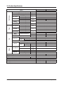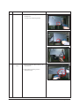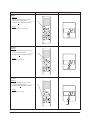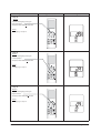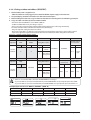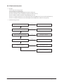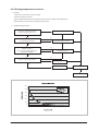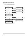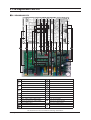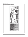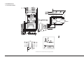
1
SYSTEM AIR CONDITIONER
Basic :
NS070LHXEA&UH070EAV2
DH070EAV1&UH070EAV2
Model :
NS035LDXEA
NS052LDXEA
NS071LDXEA
NS052SDXEA
NS071SDXEA
Model Code :
NS035LDXEA
NS052LDXEA
NS071LDXEA
NS052SDXEA
NS071SDXEA
AIR CONDITIONER
RC035DHXEA
RC052DHXEA
RC071DHXEA
RC052DHXEA
RC071DHXEA
RC035DHXEA
RC052DHXEA
RC071DHXEA
RC052DHXEA
RC071DHXEA
CONTENTS
1. Precautions
2. Product Specifications
3. Disassembly and Reassembly
NS035/052/071LDXEA
4. Troubleshooting
5. PCB Diagram and Parts List
NS052/071SDXEA
6. Wiring Diagram
7. Schematic Diagram
8. Reference Sheet
RC035/052DHXEA
RC071DHXEA
Refer to the service manual in the GSPN(see the rear cover) for the more information.
Contents
11. Precautions ........................................................................................................................................ 1-1
1-1 Installing the air conditioner
..........................................................................................................
1-1
1-2 Power supply and circuit breaker ..................................................................................................
1-1
1-3 During operation ..............................................................................................................................
1-2
1-4 Disposing of the unit
.......................................................................................................................
1-2
.................................................................................................................................................
1-2
1-5 Others
12. Product Specifications ............................................................................................................... 2-1
2-1 The Feature of Product ....................................................................................................................
2-1
2-2 Product Specifications .....................................................................................................................
2-2
2-3 The Comparative Specifications of Product ............................................................................... 2-7
2-4 Accessory and Option Specifications ............................................................................................ 2-12
3. Disassembly and Reassembly
..............................................................................................
3-1
3-1 Indoor Unit .........................................................................................................................................
3-2
3-2 Outdoor Unit
....................................................................................................................................
4. Trouble shooting
3-14
...........................................................................................................................
4-1
4-1 Indoor Display Error and Check Method ...................................................................................................
4-1
4-2 Outdoor LED Error Display and Check Method .......................................................................................
4-4
4-3 Setting Option Setup Method ........................................................................................................................
4-5
4-4 Items to be checked first ................................................................................................................................... 4-24
4-5 Fault Diagnosis by Symptom .......................................................................................................................... 4-25
4-6 PCB Inspection Method ..................................................................................................................................... 4-41
4-7 Main Part Inspection Method ......................................................................................................................... 4-43
5. PCB Diagram and Parts list ...................................................................................................... 5-1
6-1 Indoor Unit
........................................................................................................................................
6-2 Outdoor Unit
....................................................................................................................................
5-1
5-2
6. Wiring Diagram .............................................................................................................................. 6-1
1
7. Schematic Diagram ...................................................................................................................... 7-1
8-1 Indoor Unit .........................................................................................................................................
7-1
8-2 Outdoor Unit
7-2
....................................................................................................................................
8. Reference Sheet
.............................................................................................................................
9-1 Refrigerating Cycle Diagram
8-1
..........................................................................................................
8-1
9-2 Index for Model Name .....................................................................................................................
8-2
1. Precautions
1-1 Installing the air conditioner
O Users should not install the air conditioner by themselves.
Ask the dealer or authorized company to install the air conditioner except the
window-type air conditioner in U.S.A and Canada.
O If you don’t install the air conditioner properly, it may cause a fire, a water leakus
ero
ng
O You must install the air conditioner according to the national wiring regulations
da
age or an electric shock.
and safety regulations.
O Install the indoor unit higher than 2.5m from the floor to avoid the injury
caused by the operation of the fan. (except the window-type air conditioner)
O The manufacturer is not responsible for any accidents or injury caused by an
incorrect installation.
When installing the built-in type air conditioner, keep all electric cables such as
the power cable and the connection cord in pipes, ducts, or cable channels to
protect them from the danger of impact or any other incidents.
Avoid Dangerous Contact
1-2 Power supply and circuit breaker
O If the power cord of the air conditioner is damaged, it must be replaced by the manufacturer or a qualified person in order to avoid a hazard.
O The air conditioner must be plugged into an independent circuit if applicable or connect the power cable to the auxiliary circuit breaker.
An all pole disconnection from the power supply must be incorporated in the
fixed wiring with a contact opening of >3mm.
O Do not extend an electric cord to the air conditioner.
O The air conditioner must be plugged in after you complete the installation.
No Tapping and No Extension Cords
Samsung Electronics
1-1
1-3 During operation
O Do not repair the air conditioner at your discretion.
It is recommended to contact a service center directly.
O Never spill any kind of liquid on the air conditioner.
If this happens, turn off the air conditioner and contact an authorized service center.
O Do not insert anything between the airflow blades to prevent damage of the inner
fan and consequent injury. Keep children away from the air conditioner.
O Do not place any obstacles in front of the air conditioner.
O Do not spray any kind of liquid into the indoor unit. If this happens, turn off the air
conditioner and contact a service center.
O Make sure that the air conditioner is well ventilated at all times:
Do not place a cloth or other materials over it.
No children Nearby
O Remove the batteries if you don’t use the remote control for a long time. (If applicable)
O Use the remote control within 7 meters from the indoor unit. (If applicable)
1-4 Disposing of the unit
O Before throwing out the air conditioner, remove the batteries from the remote control.
O When you dispose of the air conditioner, consult your dealer. If pipes are removed incorrectly, refrigerant may blow out and cause
air pollution. When it contacts with your skin, it can cause skin injury.
O The package of the air conditioner should be recycled or disposed of properly for environmental reasons.
1-5 Others
O
O
O
O
1-2
Never store or load the air conditioner upside down or sideways to prevent the damage to the compressor.
Young children or infirm persons should be always supervised when they use the air conditioner.
Max current is measured according to IEC standard for safety.
Current is measured according to ISO standard for energy efficiency.
Samsung Electronics
2. Product Specifications
2-1 The Feature of Product
Q Built-in Cassette Type
After installed, the air conditioner can be harmonized with a room interior.
Q High Performance & Energy Saving
With the advanced BLDC inverter technology, it makes a room cool with highly energy saving and arises the efficiency of air
conditioner.
Q Long Piping(Length & Height)
It can give the benefit to the installers and aries the reliability of the air conditioner.
Q Long Ambient Operation(In Low Temperature)
It can arise the reliability and the capacity of the air conditioner, especially operated in low temperature.
Q Eco-friendly Product(Lead-Free, RoHS, WEEE)
Samsung Electronics
2-1
2-2 Product Specifications
Power
Performance
Model
Cooling(MIN/STD/MAX)
Heating(MIN/STD/MAX)
Dehumidifying
Cooling
Air Volume
Heating
Cooling
Noise
Heating
Cooling
Energy
Efficiency Ratio
Heating
Power
Cooling
Power
Consumption
Heating
Cooling
Operating
Current
Heating
Cooling
Power Factor
Heating
Outer
Dimension
W
W
ℓ/h
m³/min
(H/M/L)
dB
(H/M/L)
W/W
ph/V/Hz
W
A
%
WidthxHeightxDepth
Weight(Net)
mm
inch
kg
Size
Model
Compressor
Type
Rated Output
Motor
Oil Type
Blower
Motor
Type
Type
Rated Output
Liquid
Piping
Pipe O.D Size
Gas
Connection Method
Height
Between
Pipe Length
Heat Exerchanger
Refrigerant Control Unit
Freezer Oil Capacitor
Refrigerant to Change(R410A)
Protection Device(OLP)
Cooling Test Condition
Heating Test Condition
2-2
W
mm(inch)
xL(m)
mm(inch)
xL(m)
m
m
cc
g
Indoor Unit
Outdoor Unit
NS035LDXEA
RC035DHXEA
950/ 3500/ 4000
720/4000/4600
40
53
40
53
2.81
3.41
1/220~240V/50Hz
210/ 1245/ 1450
180/ 1173/ 1400
1.6/ 6.0/ 6.6
1.2/ 5.7/ 6.6
70/ 90/ 90
70/ 90/ 90
900*199*600
790*548*285
26
33
G4C090LUDJR
Single BLDC
320cc, POE
Blower
Propeller
SSR
BLDC
6.35(1/4)x5
9.53(3/8)x5
Flare
Max. 15
Max. 20
FP1.3*Slit*Slica
FP1.3*G-fin*SILLICA
EEV
950
DB27˚CWB19˚C
DB35˚C WB24˚C
DB20˚C WB15˚C
DB7˚C WB6˚C
Samsung Electronics
Product Specifications(cont.)
Power
Performance
Model
Cooling(MIN/STD/MAX)
Heating(MIN/STD/MAX)
Dehumidifying
Cooling
Air Volume
Heating
Cooling
Noise
Heating
Cooling
Energy
Efficiency Ratio
Heating
Power
Cooling
Power
Consumption
Heating
Cooling
Operating
Current
Heating
Cooling
Power Factor
Heating
Outer
Dimension
W
W
ℓ/h
m³/min
(H/M/L)
dB
(H/M/L)
W/W
ph/V/Hz
W
A
%
WidthxHeightxDepth
Weight(Net)
mm
inch
kg
Size
Model
Compressor
Type
Rated Output
Motor
Oil Type
Blower
Motor
Type
Type
Rated Output
Liquid
Piping
Pipe O.D Size
Gas
Connection Method
Height
Between
Pipe Length
Heat Exerchanger
Refrigerant Control Unit
Freezer Oil Capacitor
Refrigerant to Change(R410A)
Protection Device(OLP)
Cooling Test Condition
Heating Test Condition
Samsung Electronics
W
mm(inch)
xL(m)
mm(inch)
xL(m)
m
m
cc
g
Indoor Unit
Outdoor Unit
NS052LDXEA
RC052DHXEA
1200/ 5000/ 6000
700/6000/7000
42
58
42
58
3.23
3.64
1/220~240V/50Hz
230/ 1550/ 2200
280/ 1650/ 2200
1.3/ 7.0/ 9.8
1.6/ 7.5/ 10.0
95/ 97/ 95
95/ 97/ 95
1100*199*600
790*548*285
31
38.5
UG4T150FUDJQ
Twin BLDC
650cc, POE
Blower
Propeller
SSR
BLDC
6.35(1/4)x5
12.7(1/2)x5
Flare
Max. 20
Max. 30
FP1.3*Slit*Slica
FP1.4*G-fin* Hydrofile
EEV
1400 (10g/m)
DB27˚CWB19˚C
DB35˚C WB24˚C
DB20˚C WB15˚C
DB7˚C WB6˚C
2-3
Product Specifications(cont.)
Power
Performance
Model
Cooling(MIN/STD/MAX)
Heating(MIN/STD/MAX)
Dehumidifying
Cooling
Air Volume
Heating
Cooling
Noise
Heating
Cooling
Energy
Efficiency Ratio
Heating
Power
Cooling
Power
Consumption
Heating
Cooling
Operating
Current
Heating
Cooling
Power Factor
Heating
Outer
Dimension
W
W
ℓ/h
m³/min
(H/M/L)
dB
(H/M/L)
W/W
ph/V/Hz
W
A
%
WidthxHeightxDepth
Weight(Net)
mm
inch
kg
Size
Model
Compressor
Type
Rated Output
Motor
Oil Type
Blower
Motor
Type
Type
Rated Output
Liquid
Piping
Pipe O.D Size
Gas
Connection Method
Height
Between
Pipe Length
Heat Exerchanger
Refrigerant Control Unit
Freezer Oil Capacitor
Refrigerant to Change(R410A)
Protection Device(OLP)
Cooling Test Condition
Heating Test Condition
2-4
W
mm(inch)
xL(m)
mm(inch)
xL(m)
Indoor Unit
Outdoor Unit
NS071LDXEA
RC071DHXEA
2200/ 7100/ 8000
1900/8000/9000
9.54/14.2/15.88
11.37/16.87/18.68
44
60
44
60
3.21
3.61
1/220~240V/50Hz
350/ 2210/ 4000
350/ 2220/ 4000
2/ 10.5/ 21
2/ 10.5/ 21
90.6/ 97.4/ 97.76
92.1/ 97.5/ 97.3
1100*600*199
880X310X798
32
54.5
UG4T200FUAE4
Twin BLDC
8.0μF/450V
650cc, POE
Blower
Propeller
SSR
BLDC
30
40
6.35(1/4)x5
15.88(5/8)x5
Flare
Max.30
Max50
m
m
FP1.3*Slit*Slica
cc
g
FP1.3*Louver
EEV
650
1800(25g/m)
DB27˚CWB19˚C
DB35˚C WB24˚C
DB20˚C WB15˚C
DB7˚C WB6˚C
Samsung Electronics
Product Specifications(cont.)
Power
Performance
Model
Cooling(MIN/STD/MAX)
Heating(MIN/STD/MAX)
Dehumidifying
Cooling
Air Volume
Heating
Cooling
Noise
Heating
Cooling
Energy Efficiency
Ratio
Heating
Power
Cooling
Power Consumption
Heating
Cooling
Operating Current
Heating
Cooling
Power Factor
Heating
Outer Dimension
W
W
ℓ/h
m³/min
(H/M/L)
dB
(H/M/L)
W/W
ph/V/Hz
W
A
%
WidthxHeightxDepth
Weight(Net)
Indoor Unit
Outdoor Unit
NS052SDXEA
RC052DHXEA
1000/ 5000/ 6000
750/ 6000/ 7200
45
58
45
58
3.21
3.41
1/220~240V/50Hz
430/ 1560/ 2200
330/ 1760/ 2300
2.2/7.5/10.0
1.9/8.4/10.0
95/ 97/ 95
95/ 97/ 95
mm
900*260*480
790*548*285
inch
kg
29.5
38.5
Size
Model
Compressor
UG4T150FUDJQ
TWIN BLDC
650cc, POE
Type
Rated Output
Motor
Oil Type
Blower
Type
Type
Rated
Output
Motor
Liquid
Piping
Pipe O.D Size
Gas
Connection Method
Height
Between
Pipe Length
Heat Exerchanger
Refrigerant Control Unit
Freezer Oil Capacitor
Refrigerant to Change(R410A)
Protection Device(OLP)
Cooling Test Condition
Heating Test Condition
Samsung Electronics
W
mm(inch)
xL(m)
mm(inch)
xL(m)
m
m
cc
g
Blower
SSR
Propeller
BLDC
-
6.35(1/4)x5
12.7(1/2)x5
Flare
Max. 20
Max. 30
FP1.3*H-fin*Slica
FP1.4*G-fin,*Hydrofile
EEV
1400(10g/m)
DB27˚CWB19˚C
DB35˚C WB24˚C
DB20˚C WB15˚C
DB7˚C WB6˚C
2-5
Product Specifications(cont.)
Power
Performance
Model
Cooling(MIN/STD/MAX)
Heating(MIN/STD/MAX)
Dehumidifying
Cooling
Air Volume
Heating
Cooling
Noise
Heating
Cooling
Energy Efficiency
Ratio
Heating
Power
Cooling
Power Consumption
Heating
Cooling
Operating Current
Heating
Cooling
Power Factor
Heating
Outer Dimension
W
W
ℓ/h
m³/min
(H/M/L)
dB
(H/M/L)
W/W
ph/V/Hz
W
A
%
WidthxHeightxDepth
Weight(Net)
Indoor Unit
Outdoor Unit
NS071SDXEA
RC071DHXEA
2200/ 7100/ 8000
1900/ 8000/ 9000
17.86/19.84/20.65
15.27/20.03/22.48
45
60
45
60
3.21
3.61
1/220~240V/50Hz
350/ 2210/ 4000
350/ 2220/ 4000
2/10.5/21.0
2/10.5/21.0
90.2/ 97/ 97.3
90.3/ 97.2/ 97.6
mm
1150*480*260
880X310X798
inch
kg
33
54.5
Size
Model
Compressor
UG4T200FUAE4
TWIN BLDC
8.0μF/450V
650cc, POE
Type
Rated Output
Motor
Oil Type
Blower
Type
Type
Rated
Output
Motor
Liquid
Piping
Pipe O.D Size
Gas
Connection Method
Height
Between
Pipe Length
Heat Exerchanger
Refrigerant Control Unit
Freezer Oil Capacitor
Refrigerant to Change(R410A)
Protection Device(OLP)
Cooling Test Condition
Heating Test Condition
2-6
W
Blower
SSR
Propeller
BLDC
30
40
mm(inch)
xL(m)
mm(inch)
xL(m)
15.88(5/8)x5
m
m
Flare
Max.30
Max50
6.35(1/4)x5
FP1.3*Slit*Slica
cc
g
FP1.3*Louver
EEV
650
1800(25g/m)
DB27˚CWB19˚C
DB35˚C WB24˚C
DB20˚C WB15˚C
DB7˚C WB6˚C
Samsung Electronics
2-3 The Comparative Specifications of Product
Item
NS035LDXEA/RC035DHXEA
NS035LHXEA/UH035EAV1(Basic)
Indoor Unit
26.0kg
22.0kg
Outdoor Unit
33.0kg
50.0kg
Indoor Unit
990x199x600mm
990x199x600mm
Outdoor Unit
790x548x285mm
790x548x285mm
Indoor Unit
40dB↓
40dB↓
Outdoor Unit
53dB↓
53dB↓
Indoor Unit
Design
Outdoor Unit
Net Weight
Outer Dimension
(WxHtxD)
Noise
Samsung Electronics
2-7
The Comparative Specifications of Product(cont.)
Item
NS052LDXEA/RC052DHXEA
NS052LHXEA/UH052EAV1(Basic)
Indoor Unit
26.0kg
26.0kg
Outdoor Unit
33.0kg
50.0kg
Indoor Unit
990x199x600mm
990x199x600mm
Outdoor Unit
790x548x285mm
790x548x285mm
Indoor Unit
42dB↓
42dB↓
Outdoor Unit
58dB↓
58dB↓
Indoor Unit
Design
Outdoor Unit
Net Weight
Outer Dimension
(WxHtxD)
Noise
2-8
Samsung Electronics
The Comparative Specifications of Product(cont.)
Item
NS071LDXEA/RC071DHXEA
NS071LHXEA/UH071EAV2(Basic)
Indoor Unit
32.0kg
32.0kg
Outdoor Unit
54.5kg
54.5kg
Indoor Unit
1100x600x199mm
1100x600x199mm
Outdoor Unit
880x310x798mm
880x310x798mm
Indoor Unit
44dB↓
44dB↓
Outdoor Unit
60dB↓
60dB↓
Indoor Unit
Design
Outdoor Unit
Net Weight
Outer Dimension
(WxHtxD)
Noise
Samsung Electronics
2-9
The Comparative Specifications of Product(cont.)
Item
NS052SDXEA/RC052DHXEA
DH052EAV1/UH052EAV1(Basic)
Indoor Unit
29.5kg
29.5kg
Outdoor Unit
38.5kg
38.5kg
Indoor Unit
900*260*480 mm
900*260*480mm
Outdoor Unit
790x548x285mm
790x548x285mm
Indoor Unit
45dB↓
45dB↓
Outdoor Unit
58dB↓
58dB↓
Indoor Unit
Design
Outdoor Unit
Net Weight
Outer Dimension
(WxHtxD)
Noise
2-10
Samsung Electronics
The Comparative Specifications of Product(cont.)
Item
NS071CDXEA/RC071DHXEA
DH070EAV1/UH070EAV2(Basic)
Indoor Unit
33.0kg
33.0kg
Outdoor Unit
54.5kg
54.5kg
Indoor Unit
1150*480*260mm
1150*480*260mm
Outdoor Unit
880*310*798mm
880*310*798mm
Indoor Unit
45dB↓
45dB↓
Outdoor Unit
60dB↓
60dB↓
Indoor Unit
Design
Outdoor Unit
Net Weight
Outer Dimension
(WxHtxD)
Noise
Samsung Electronics
2-11
2-4 Accessory and Specifications
Item
Descriptions
Code-No.
Q'TY
Wired remote controller
DB97-15070D
1
Owner's Manual
DB98-32657A
1
Installation Manual
DB98-32737A
1
Insulation
DB62-04318S
1
Insu Drain Hose
DB62-11028A
1
DB62-11208E
1
DB62-11208D
1
Cable Tie
DB65-10088C
8
Grommet Hanger
DB63-00237A
8
Ass'y Drain Hose Joint
DB94-03287A
1
RUBBER LEG
DB73-20134A
4
DRAIN PLUG
DB67-20011A
1
INSTALLATION MANUAL
DB98-34367A
1
Remark
TIONS
OWNER'S INSTRUC
INSTRUCCIONES
MANUAL DE
PER L'USO
ISTRUZIONIINSTRU‚Í
ES
MANUAL DE ATION
MANUEL D'UTILISEISUNG
GEBRAUCHSANW
Air ConditionerSplit
Splut-type Room
domĿstico sistema
ad unitˆ Separate
Aire acondicionado
d'aria per ambienti
Split
Condizionatorede ar condicionado tipo
Aparelho
type sĿparĿ
Climatiseur de
e
Geteilte raumklimaanlag
Indoor
Unit
Insu Hose
2-12
Outdoor unit
Samsung Electronics
3. Disassembly and Reassembly
■ Necessary Tools
Item
Remark
+SCREW DRIVER
MONKEY SPANNER
Samsung Electronics
3-1
3-1 Indoor Unit
Stop operation of the air conditioner and remove the power cord before repairing the unit.
■ NS035/052/071LDXEA
No
Parts
1
Filter
Procedure
Remark
1) Pull out the Filter as picture 1 or picture 2.
2) If it is necessary, after disassembling
8 indicating screws, detach the
Bracket Filter.
3-2
Samsung Electronics
No
Parts
Procedure
Remark
3) If the Cabinet-Top Motor is assembled
on the side of the set, the procedure of
disassembling the Filter is just as the
above.
2
Blower
&
Motor
1) After disassembling 13 indicating screws,
detach Ass’y Cabinet-Top Motor.
2) After disassembling 3 indicating screws,
detach Ass’y Case Blower Upper.
– Press the pothook of the Case Blower
and detach Ass’y Case Blower Upper.
Samsung Electronics
3-3
No
Parts
Procedure
Remark
3) After disassembling 2 indicating screws,
detach the Cover Control.
4) Detach the Motor Wire Connected to
PCB and Capacitor.
5) After disassembling the indicating
screws, detach the wire connected to
the Partition.
6) After disassembling 2 indicating screws,
detach the Ass’y Band Motor.
3-4
Samsung Electronics
No
Parts
Procedure
Remark
7) After disassembling the Motor and Blowers,
detach the Blowers from the axis of the
Motor by 3mm inner hexagon spanner.
3
Drain Pan
1) After disassembling 15 indicating screws,
detach Ass’y Cabinet-Top Evap.
2) After disassembling 6 indicating screws,
detach the Bracket Outlet.
3) Detach the Drain Pan.
Samsung Electronics
3-5
No
Parts
4
Evaporator
Procedure
Remark
7 After finished the procedures above,
detach the Evaporator.
1) After disassembling 2 indicating screws,
detach Ass'y Cover Pipe.
2) Detach the Sensor from the
Control Box.(including 2 Sensors)
3) After disassembling 2 indicating screws,
detach Ass'y Support Evap LF.
4) After disassembling 2 indicating screws,
detach Ass'y Support Evap RH.
3-6
Samsung Electronics
No
Parts
Procedure
Remark
5) Detach the Evaporator from the set.
5
Control In
7 Detach the parts of Control In after
disassembling the Cover Control.
1) Detach all the wires connected to the PCB.
2) If only the disassembly of PCB required,
press the Pothook and detach the PCB
from the set.
3) If only the disassembly of Capacitor is
required, detach it from the set.
4) If only the disassembly of Case Control is
required, detach it from the set after
disassembling 2 indicating screws.
Samsung Electronics
3-7
No
Parts
Procedure
Remark
5) Detach the Transformer after
disassembling 2 indicating screws.
7Work is possible after disassembling
the Case PCB.
6
3-8
Ass’y Bracket
Outlet
1) After disassembling 16 indicating screws,
detach Ass’y Bracket Outlet.
Samsung Electronics
■ NS052/071SDXEA
No
Parts
1
Blower & Motor
Procedure
Remark
1) After disassembling 16 places indicating
screws, detach Ass'y Cabi Bottom Blower.
2) Detach from Ass'y Control In the
capacitor connection wire between the
Motor Fan and housing connector.
3) After disassembling 2 places indicating
screws, detach the 2 Fan Case.
Samsung Electronics
3-9
No
Parts
Procedure
Remark
4) After disassembling 2 places indicating
screws, detach Fan Motor and Blower from
the set.
2
Control In
1) After disassembling 1 Indicating screw,
detach the Cover control.
2) Detach the Motor-Fan and Sensor Connector
from the PCB.
3-10
Samsung Electronics
No
Parts
Procedure
Remark
3) Disassemble 4 indicating screws and detach
Control In from the set.
3
Drain Pan
Work is possible when Disassembling the
Ass'y Cabi Bottom Blower.
1) Disassemble 7 indicating screws and detach
Ass'y Cabi Bottom Drain.
Samsung Electronics
3-11
No
Parts
Procedure
Remark
2) Disassemble 4 indicating screws and detach
the Drain Pan.
(2 screws each at left and right side)
4
Evap
Work is possible when Disassembling the
Ass'y Drain Pan.
1) Disassemble 5 indicating screws to
detach Cover Pipe.
3-12
Samsung Electronics
No
Parts
Procedure
Remark
2) Disassemble Sensor on the Evap.
3) Disassemble 4 indicating screws which are in
the near of Hanger Plate to detach the Evap.
(2 screws each at left and right side)
It needs 2 peoples.
Samsung Electronics
3-13
3-2 Outdoor Unit
■ RC071DHXEA
No
Parts
Procedure
1
Common Work
1) Loosen 1 fixing screw of the Cover-Control
and detach the Cover Control.
Remark
2) Loosen each 7 fixing screws and detach
the Cabinet Upper.
3-14
Samsung Electronics
No
Parts
Procedure
Remark
3) Loosen 2 screws fixed to assemble
Control Box with Cabinet-Side RH.
4) Loosen fixing screws and detach the
Cabinet-Side RH.
5) Loosen 2 screws fixed on the Guide
Condenser.
Samsung Electronics
3-15
No
Parts
Procedure
Remark
6) Loosen fixing screws of the Cabinet Front.
3-16
Samsung Electronics
No
Parts
Procedure
3
ASS'Y Control Out
1) Detach several connectors from the
ASS'Y Control Out.
2) Detach several connectors from the PCB
of ASS'Y Control Out.
3) Pull up the ASS'Y Control Out.
4
Heat Exchanger
1) Release the refrigerant at first.
2) Loosen fixing screw on both sides.
3) Disassemble the pipes in both inlet and
outlet with welding torch.
4) Detach the Heat Exchanger.
Remark
5) Loosen 4 bolts fixed to assemble Valve
Service with Bracket Valve like the picture
on the right side.
Samsung Electronics
3-17
No
Parts
2
Fan
&
Motor
Procedure
Remark
1) Detach the Nut Flange like the picture on
the right side. (Turn counter clockwise
because the screw is right-handed.)
2) Detach the Fan Propeller.
3) Loosen 4 fixing screws to detach the Motor.
4) Disconnect the wire between ASS'Y
Control Out and Motor.
5) Loosen 2 fixing bolts and detach the
Bracket Motor.
3-18
Samsung Electronics
No
Parts
5
Compressor
Procedure
Remark
1) Loosen the fixing nut and detach the
Compressor Lead Wire.
2) Disassemble the Felt Compressor Sound.
3) Loosen the 3 bolts at the bottom of
Compressor like the picture on the
right side.
Samsung Electronics
3-19
QRC026DHXEA/ RC035DHXEA/ RC052DHXEA
No
Parts
Procedure
1
common work
1) loosen 1 pcs screw of cover control,and
detach it.
Remark
2) loosen 5 pcs screws on both right and
left cabniet side edges and to detach the
cover-top
3) Loosen 7 screwsfixed to disassemble
cabi-front , and detach it.
3-20
Samsung Electronics
No
Parts
common work
Procedure
Remark
4) loosen 7 screws to disassemble the cabiright ,and detach it.
5) loosen 2 screws to disassemble steel-bar.
6) loosen 3 screws to disassemble cabi-left.
Samsung Electronics
3-21
No
Parts
Procedure
2
fan&motor
1) loosen 1 screw as indication and detached
the fan.
Remark
2) loosen 4 pcs motor screws and disconnect
the wire betwwen assy control out and motor.
3) loosen 2 pcs bracket-motor screw and
detach it.
3-22
Samsung Electronics
No
Parts
3
assy control out
1) lossen fixing 1 screw from cover -control
2) detach several connections from assy control out, take out assy control out.
4
Heat exchanger
1) Release the refrigerant at first
2) Looosen fixing screw on both side.
3) disaessembly the pipes in both inlet and
outlet with welding torch.
4) detach the heat exchanger.
Samsung Electronics
Procedure
Remark
3-23
No
Parts
5
compressor
Procedure
Remark
1) disconnect the compressor lead wire .
2)disassembly the felt comp sound.
loosen the 3 bolts at the bottom of
3-24
Samsung Electronics
4. Troubleshooting
4-1 Indoor Display Error and Check Method
Q Error detection and reoperation
X If error occurs during the operation, badness is indicated by LED flickering and all operation is stopped except LED.
X When reoperating by remote control and switch determine the error mode after normal operation.
Q Indoor unit LED lamp display at error detecting
LED lamp display
Operation
Defrost
Timer
Air flow
Filter
Power reset
◑
X
X
X
X
Error of temperature sensor
in the indoor unit(Open/Short)
X
X
◑
X
X
Error of heat exchanger sensor
in the indoor unit
◑
X
◑
X
X
Error of the outdoor temperature sensor
Error of the condensor temperature sensor
Error of the discharge temperature sensor
◑
X
X
◑
X
1. No communication for 2 minutes between indoor units
(Communication error for more than 2 minutes)
2. Indoor unit receiving the communication error from
outdoor unit
3. Outdoor unit tracking 3 minutes error
4. When sending the communication error from the outdoor
unit, the mismatching of the communication numbers and
installed numbers after completion of tracking
4. (Communication error for more than 2 minutes)
X
X
◑
◑
X
1. Error of electronic expansion valve close
2. Error of electronic expansion valve open
3. 2'nd detection of high temperature cond
4. 2'nd detection of high temperature discharge
5. Error of reverse phase
6. Compressor down due to 6'th detection of freezing
X
X
◑
◑
◑
Detection of the float switch
X
X
X
◑
◑
Error of setting option switches for optional accessories
X
X
◑
X
◑
EEPROM option error
◑
◑
◑
◑
◑
Error type
Remarks
● : On, ◑ : Flickering, X: OFF
K If you turn off the air conditioner when the LED is flickering, the LED is also turned off.
Samsung Electronics
4-1
Q Wired Remocon Error Display
t If an error occurs, is displayed on the wired remote controller.
t If you would like to see an error code, press the Test button.
Display
Explanation
Indoor unit Communication Error
Remark
Communication Error
Indoor/Outdoor unit Communication Time Out Error 60 Packet Over data
Indoor unit is not connected
Communication Error between Outdoor Main and Inverter Micom
(Occurred after 1 minute detection in Main and Inverter)
Indoor Temp. Sensor(Open/Short Error)
Indoor Sensor Error
Indoor Unit Eva in Sensor(Open/Short Error)
Indoor Unit Eva in Sensor Separation
Outdoor Temp. Sensor Error(Open/Short Error)
Outdoor Sensor Error
COND Temp. Sensor Error(Open/Short Error)
Inverter Compressor Discharge Temp. sensor Error(Open/Short Error)
Power cable miss connection error
Indoor Float Switch 2nd Detection
Self Diagnosys Error
Outdoor unit - indoor unit communication wire miss connection
(Connected to Power terminal)
Outdoor unit refrigerant Full leakage(Gas leak)
Outdoor Fan 1 Error
Outdoor Fan 2 Error
Discharge over temperature
Outdoor Unit
Protetion Control Error
[Inverter] Compressor starting error
Primary Current Over Trip error
[Inverter]IPM Over Current(O.C)
[Inverter] Compressor Rotation error
[Inverter] Current Sensor error
[Inverter] DC LINK Sensor error
[Inverter] EEPROM Read/Write Error
4-2
Samsung Electronics
Display
Explanation
[Inverter] Heatsink temperature over Error
Remark
Outdoor Unit
Protetion Control Error
Outdoor unit Capacity Setup option error
Communication error between Indoor unit and wired remote control
Wired remote control error
Communication error between Master and Slave wired remote control
COM1/COM2 Cross-installed error
Error of setting option for wired remote control COM2
Samsung Electronics
4-3
4-2 Outdoor Unit Error Display
If an error occurs during the operation, it is displayed on the outdoor unit PCB LED, both MAIN PCB and INVERTER PCB.
No.
Error Code
Meaning
Remarks
1
E201
Unit quantity miss matching between indoor and outdoor.
Check indoor quantity setting in outdoor (Refer to
page 17.)
2
E202
Abnormal state, no communication between Indoor and Outdoor
Main PCB
Check electrical connection and setting
3
E203
1min. Time out of communcation error(Main¥Inverter)
Check electrical connection and setting
4
E221
Outdoor temp sensor error
Check Outdoor sensor Open/Short
5
E231
Cond. temp sensor error
Check Cond. sensor Open/Short
6
E251
Discharge temp sensor error
Check Discharge sensor Open/Short
7
E320
OLP Sensor Error
Check OLP sensor Open/Short
8
E403
Detection of Outdoor Freezing when Comp. Stop
Check Outdoor Cond.
9
E404
Protection of Outdoor Overload when Comp. Stop
Check Comp. when it start
10
E416
Discharge temperature of a compressor in an
outdoor unit is overheated.
Heating operation is not available since the outdoor air temperature is over 30°C.
Cooling operation is not available since the outdoor air temperature is lower than -5°C.
Heating
E440
11
E441
Cooling
12
E458
E475
Outdoor unit BLDC Fan 1 or Fan 2 error
13
E461
Comp. Starting error
14
E462
Primary Current Trip error
15
E463
Over current trip / PFC over current error
16
E464
IPM(IGBT Module) Over Current(O.C)
17
E465
Comp. Over load error
18
E466
DC-Link voltage under/over error
Check AC Power or DC_Link voltage
19
E467
Comp. wire missing error
Check Comp. wire
20
E468
Current sensor error
Check Outdoor Inverter PBA
21
E471
Outdoor EEPROM error
Check Outdoor EEPROM date
22
E474
IPM(IGBT Module) or PFCM Temperature sensor Error
Check Outdoor Inverter PBA
23
E484
PFC Overload Error
Check Outdoor Inverter PBA
24
E500
IPM is over heated.
Check Outdoor Inverter PBA
25
E554
GAS Leak error
Check indoor and outdoor unit model
26
E556
Capacity miss match between indoor and outdoor
Check indoor and outdoor unit model
4-4
FAN1 error
FAN2 error
Check OLP sensor
Samsung Electronics
4-3 Setting Option Setup Method
4-3-1 Type A (Setting Option)
Option No. :
Step 1 : Enter the Option Setup mode.
1st Take out the batteries of remote control.
2nd Press the temperature
insert the battery again.
button simultaneously and
3rd Make sure the remocon display shown as
.
Step 2 : Enter the Option Setup mode and select your option according to the following procedure.
1
The default value is
.
Otherwise, push the
button to
.
Every time you push the button, the display panel reads
or
repeatedly.
1
2
2
Push the
3
button to set the display panel to
.
Every time you push the button, the display panel reads
➡
➡...
➡
➡
➡
➡
➡
➡
➡
➡
repeatedly.
4
3
Push the
button to set the display panel to
.
5
Every time you push the button, the display panel reads
6
➡
➡...
➡
➡
➡
➡
➡
➡
➡
➡
repeatedly.
4
Push the
button to set the display panel to
.
Every time you push the button, the display panel reads
➡
➡...
➡
➡
➡
➡
➡
➡
➡
➡
repeatedly.
5
Push the
button to set the display panel to
.
Every time you push the button, the display panel reads
➡
S Setting is not required if you must
a value which has a default.
➡...
➡
➡
➡
➡
➡
➡
➡
6
Push the
button to set the display panel to
.
Every time you push the button, the display panel reads
➡
Samsung Electronics
➡
repeatedly.
➡...
➡
➡
➡
➡
➡
➡
➡
➡
repeatedly.
4-5
7
1
Press
button, then the default value is
.
8
Push the
7
button to set the display panel to
.
Every time you push the button, the display panel reads
8
➡
9
➡...
➡
➡
➡
➡
➡
➡
➡
➡
repeatedly.
9
Push the
10
button to set the display panel to
.
Every time you push the button, the display panel reads
➡
➡...
➡
➡
➡
➡
➡
➡
➡
➡
repeatedly.
11
10
12
Push the
button to set the display panel to
.
Every time you push the button, the display panel reads
➡
➡...
➡
➡
➡
➡
➡
➡
➡
➡
repeatedly.
11
Push the
button to set the display panel to
.
Every time you push the button, the display panel reads
➡
➡...
➡
➡
➡
➡
➡
➡
➡
➡
repeatedly.
12
S Setting is not required if you must
a value which has a default.
Push the
button to set the display panel to
.
Every time you push the button, the display panel reads
➡
➡...
➡
➡
➡
➡
➡
➡
➡
➡
repeatedly.
Step 3 : Upon completion of the selection, check you made right selections.
Press the Mode Selection key,
to set the display part to and check the display part.
➡ The display part shows
.
Press the Mode Selection key,
➡ The display part shows
to set the display part to
and check the display part.
.
Step 4 : Pressing the ON/OFF button( )
When pressing the operation ON/OFF key with the direction of remote control for unit, the sound ’’Ding’’ or ’’Diriring’’
is heard and the OPERATION ICON( ) lamp of the display is flickering at the same time, then the input of option is completed.
(If the diriring sound isn’t heard, try again pressing the ON/OFF button.)
Step 5 : Unit operation test-run
First, Remove the battery from the remote control.
Second, Re-insert the battery into the remote control.
Third, Press ON/OFF button( ) with the direction of remote control for set.
t&SSPS.PEF
1st
nd
2
4-6
If all lamps of indoor unit are flickering, Plug out, plug in power plug again and press ON/OFF key to retry.
If the unit is not working properly or all lamps are continuously flickering after setting the option code, see if the
correct option code is set up for its model.
Samsung Electronics
4-3-2 Type B( Setting Option Setup Method)
Operation method
Applicable button
Indicating state
K Step 1
Method)
① Remove the battery of remote
controller.
② Push the Off Timer and Cancel button
simultaneously.
③Insert the battery.
Result)
When the display of remote
controller is indicated as shown
in the right, then go to the step 2.
K Step 2
Method)
If the first digit of remote
controller shows "0", go to the step 3.
t*GJUTIPXTQSFTTUIF.PEFCVUUPOPOFUJNF
to change it into 0 and then go to step 3.
K Step 3
Method)
Input the second digit of option code by
pressing the High Temp button.
example) 021E311422852A311439421F
Result)
If 2 is displayed, go to the step 4 (whenever
pressing the button, 1~9, A,B,C,D,E,F are lit in
order.)
Samsung Electronics
4-7
Operation method
Applicable button
Indicating state
KStep 4
Method)
Input the third digit of option code by
pressing the Low Temp button.
example) 021E311422852A311439421F
Result)
If 1 is displayed, go to the step 5.
K Step 5
Method)
Input the fourth digit of option code by
pressing the High Fan button.
example) 021E311422852A311439421F
Result)
If E displays, go to step 6.
K Step 6
Method)
Input the fifth digit of option code by
pressing the On Timer button.
example) 021E311422852A311439421F
Result)
If 3 displays, go to step 7.
SEG5
4-8
Samsung Electronics
Operation method
Applicable button
Indicating state
K Step 7
Method)
Input the sixth digit by pressing the
Cancel button.
example) 021E311422852A311439421F
Result)
If 1 displays, go to step 8.
K Step 8
Method)
After completion up to step 7, pressing
Mode button.
① 1~7 steps are saved internally.
② If the first number is 1 at the time,
it is correct. So go to step 9.
t*GXBOUJOHUPTFFUIFTDSFFO
of 2~7 steps, press the mode button
repeatedly to make the first digit 0.
KStep 9
Method)
Input the eighth digit by pressing the
High Temp button.
example) 021E311422852A311439421F
Result)
If 4 displays, go to step 10.
Samsung Electronics
4-9
Operation method
Applicable button
Indicating state
K Step 10
Method)
Input the ninth digit by pressing the
Low Temp button.
example) 021E311422852A311439421F
Result)
If 2 displays, go to step 11.
KStep 11
Method)
Input the tenth digit by pressing the High Fan
button.
example) 021E311422852A311439421F
Result)
If 2 displays, go to step 12.
KStep 12
Method)
Input the 11st digit by pressing the
On Timer button.
example) 021E311422852A311439421F
Result)
If 8 displays, go to step 13.
4-10
Samsung Electronics
Operation method
Applicable button
Indicating state
K Step 13
Method)
Input the 12th digit by pressing the
Cancel button.
example) 021E311422852A311439421F
Result)
If 5 displays, go to step 14.
KStep 14
Error
Method)
① If the On/Off, Timer and Fan
indicator is flickering, the wrong option
After completion up to step 13, pressing
Mode button.
code is input. Put off the power of
① Previous steps are saved internally.
indoor unit and turn it on again and
② If the first number is 2 at the time, it is
rect. So go to step 15.
cor-
then input the option code again.
If the same error occurs, it is the
t*GXBOUJOHUPTFFQSFWJPVTTDSFFOQSFTTUIF
EEPROM is defective or not
mode button repeatedly to make the first digit
inserted. Replace the PCB.
to with digit.
② If all of On/Off, Timer, Fan and Filter
Sign indicator are flickering along with
the "Tiriring" sound, there is option
code already input which are different
from the current ones.
Check the option code and press the
button again if correct. Option code will
be input.(Check the option code
correctly. At the time, if the same error
continues to occur, the option code is
out of input range.
Check the option code again and repeat
the step 1~14.
Samsung Electronics
4-11
Operation method
Applicable button
Indicating state
K Step 15
Method)
Input the 14th digit by pressing the
High Temp button.
example) 021E311422852A311439421F
Result)
If A displays, go to step 16.
K Step 16
Method)
Input the 15th digit by pressing the
Low Temp button.
example) 021E311422852A311439421F
Result)
If 3 displays, go to step 17.
K Step 17
Method)
Input the 16th digit by pressing the
High Fan button.
example) 021E311422852A311439421F
Result)
If 1 displays, go to step 18.
4-12
Samsung Electronics
Operation method
Applicable button
Indicating state
K Step 18
Method)
Input the 17th digit by pressing the
On Timer button.
example) 021E311422852A311439421F
Result)
If 1 displays, go to step 19.
YStep 19
Method)
Input the 18th digit by pressing the
Cancel button.
example) 021E311422852A311439421F
Result)
If 4 displays, go to step 20.
K Step 20
Method)
After completion up to step 20, pressing
Mode button.
① Previous steps are saved internally.
② If the first number is 3 of the time,
it is correct. so go to step 22.
t*GXBOUJOHUPTFFQSFWJPVTTDSFFOQSFTTUIF
mode button repeatedly to make the first
digit to with digit.
Samsung Electronics
4-13
Operation method
Applicable button
Indicating state
K Step 21
Method)
Input the 20th digit by pressing the
High
Temp button.
example) 021E311422852A311439421F
Result)
If 9 displays, go to step 22.
K Step 22
Method)
Input the 21th digit by pressing the
Low Temp button.
example) 021E311422852A311439421F
Result)
If 4 displays, go to step 23.
YStep 23
Method)
Input the 22th digit by pressing the
High Fan button.
example) 021E311422852A311439421F
Result)
If 2 displays, go to step 24.
4-14
Samsung Electronics
Operation method
Applicable button
Indicating state
K Step 24
Method)
Input the 23th digit by pressing the
On Timer button.
example) 021E311422852A311439421F
Result)
If 1 displays, go to step 25.
K Step 25
Method)
Input the 24th digit by pressing the
Cancel button.
example) 021E311422852A311439421F
Result)
If F displays, go to step 26.
K Step 26
Method)
Turn the remote controller toward the indoor
unit and press the Power button, and if the
"Ting" or "Tiriring" sounds, the input of option is
completed.
t*GFSSPSEJTQMBZTTPMWFUIF
problem with reference to the right side.
Samsung Electronics
Error
① If the On/Off, Timer and Fan
indicator is flickering, the wrong option
code is input. Put off the power of
indoor unit and turn it on again and
then input the option code again.
If the same error occurs, it is the
EEPROM is defective or not
inserted. Replace the PCB.
② If all of On/Off, Timer, Fan and Filter Sign
indicator are flickering along with the
"Tiriring" sound, there is option code
already input which are different from
the current ones.
Check the option code and press the
button again if correct. Option code will
be input.(Check the option code
correctly. At the time, if the same error
continues to occur, the option code is
out of input range.
Check the option code again and repeat
the step 1~26.
4-15
Operation method
Applicable button
Error
① If the On/Off, Timer and Fan
indicator is flickering, the wrong option
code is input. Put off the power of
indoor unit and turn it on again and
then input the option code again.
If the same error occurs, it is the
EEPROM is defective or not inserted.
Replace the PCB.
K Step 27
Method)
If the steps 1 to 26 are completed, remove
the battery and insert it again to return to
the original display of remote controller.
(Operation mode/SET TEMP.
/fan speed displays.)
rear side
4-16
Indicating state
② If all of On/Off, Timer, Fan and Filter
Sign indicator are flickering along with
the "Tiriring" sound, there is option
code already input which are different
from the current ones.
Check the option code and press the
button again if correct. Option code will
be input.(Check the option code
correctly. At the time, if the same error
continues to occur, the option code is
out of input range.
Check the option code again and repeat
the step 1~26.
Samsung Electronics
4-3-3 Setting an indoor unit address and installation option
▶ Set the indoor unit address and installation option with remote controller option.
Set the each option separately since you cannot set the ADDRESS setting and indoor unit installation setting option at the
same time.You need to set twice when setting indoor unit address and installation option.
▶ Please use the proper wireless remocon which can set 24 digit option code. Following is the instructions of setting option
code with wireless remocon of MR-DH00. (MR-AH01 can be used for operating but cannot be used for setting the installation
option because only 12 digit option setting is available.
▶ Please refer to the wired remocon installation manual for setting with the wired remocon.
4-3-3-1 The procedure of setting option
Entering mode for
setting option
Option setting mode
Mode change
High Temp Button
High Fan Button
Low Temp Button
Low Fan Button
Step 1. Entering mode to set option
1. Remove batteries from the remote controller.
2. Insert batteries and enter the option setting mode while pressing High Temp button and Low Temp button.
3.
Check if you have entered the option setting status.
Step 2. The procedure of option setting
After entering the option setting status, select the option as listed below.
Option setting is available from SEG1 to SEG 24
t 4&(4&(4&(4&(BSFOPUOFFEUPCFTFUBU.3%)5IFZBSFUIFQBHFPQUJPOTXIJDIXFSFVTFEBUUIF
previous other remocons.
t 4FUUIFFBDICJUPQUJPODPEFJOPSEFSFYDFQUQBHFPQUJPOT
For example : SEG2, 3 SEG4, 5 SEG6, 8 SEG9, 10 SEG11, 12 SEG 14, 15 SEG 16, 17 SEG 18, 20
SEG 21, 22 SEG23, 24.
SEG1 SEG2 SEG3 SEG4 SEG5 SEG6 SEG7 SEG8 SEG9 SEG10 SEG11 SEG12
0
X
X
X
X
X
1
X
X
X
X
X
SEG13 SEG14 SEG15 SEG16 SEG17 SEG18 SEG19 SEG20 SEG21 SEG22 SEG23 SEG24
2
X
X
X
X
X
3
X
X
X
X
X
Samsung Electronics
On(SEG1~12)
Off(SEG13~24)
4-17
4-3-3-2 The procedure of setting option
Option setting
1. Setting SEG2, SEG3 option
Press Low Fan button(∨) to enter SEG2 value.
Press High Fan button(∧) to enter SEG3 value.
…
Each time you press the button,
will be selected in rotation.
Status
SEG2
SEG3
SEG4
SEG5
SEG6
SEG8
SEG9
SEG10
SEG11
SEG12
SEG14
SEG15
2. Setting Cool mode
Press Mode button to be changed to Cool mode in the ON status.
3. Setting SEG4, SEG5 option
Press Low Fan button(∨) to enter SEG4 value.
Press High Fan button(∧) to enter SEG5 value.
Each time you press the button,
…
will be selected in rotation.
4. Setting Dry mode
Press Mode button to be changed to DRY mode in the ON status.
5. Setting SEG6, SEG8 option
Press Low Fan button(∨) to enter SEG6 value.
Press High Fan button(∧) to enter SEG8 value.
…
Each time you press the button,
will be selected in rotation.
6. Setting Fan mode
Press Mode button to be changed to FAN mode in the ON status.
7. Setting SEG9, SEG10 option
Press Low Fan button(∨) to enter SEG9 value.
Press High Fan button(∧) to enter SEG10 value.
…
will be selected in rotation.
Each time you press the button,
8. Setting Heat mode
Press Mode button to be changed to HEAT mode in the ON status.
9. Setting SEG11, SEG12 option
Press Low Fan button(∨) to enter SEG11 value.
Press High Fan button(∧) to enter SEG12 value.
…
will be selected in rotation.
Each time you press the button,
10. Setting Auto mode
Press Mode button to be changed to AUTO mode in the OFF status.
11. Setting SEG14, SEG15 option
Press Low Fan button(∨) to enter SEG14 value.
Press High Fan button(∧) to enter SEG15 value.
…
will be selected in rotation.
Each time you press the button,
4-18
Samsung Electronics
The procedure of setting option (cont.)
Option setting
Status
12. Setting Cool mode
Press Mode button to be change to Cool mode in the OFF status.
13. Setting SEG16, SEG17 option
Press Low Fan button(∨) to enter SEG16 value.
Press High Fan button(∧) to enter SEG17 value.
…
will be selected in rotation.
Each time you press the button,
SEG16
SEG17
SEG18
SEG20
SEG21
SEG22
SEG23
SEG24
14. Setting Dry mode
Press Mode button to be change to Dry mode in the OFF status.
15. Setting SEG18, SEG20 option
Press Low Fan button(∨) to enter SEG18 value.
Press High Fan button(∧) to enter SEG20 value.
…
will be selected in rotation.
Each time you press the button,
16. Setting Fan mode
Press Mode button to be change to Fan mode in the OFF status.
17. Setting SEG21, SEG22 option
Press Low Fan button(∨) to enter SEG21 value.
Press High Fan button(∧) to enter SEG22 value.
…
will be selected in rotation.
Each time you press the button,
18. Setting Heat mode
Press Mode button to be change to HEAT mode in the OFF status.
19. Setting SEG23, SEG24 mode
Press Low Fan button(∨) to enter SEG23 value.
Press High Fan button(∧) to enter SEG24 value.
…
will be selected in rotation.
Each time you press the button,
Step 3. Check the option you have set
After setting option, press
Option
button to check whether the option code you input is correct or not.
[SEG2,3]
[SEG4,5]
[SEG6,8]
[SEG9,10]
[SEG11,12]
[SEG14,15]
[SEG16,17]
[SEG18,20]
[SEG21,22]
[SEG23,24]
Remote Controller Display
Option
Remote Controller Display
Step 4. Input option
with the direction of remote control for set.
Press operation button
For the correct option setting, you must input the option twice.
Step 5. Check operation
1. Reset the indoor unit by pressing the RESET button of indoor unit or outdoor unit.
2. Take the batteries out of the remote controller and insert them again and then press the operation button.
Samsung Electronics
4-19
4-3-3-3 Setting an indoor unit address (MAIN/RMC)
1. Check whether power is supplied or not.
- When the indoor unit is not plugged in, there should be additional power supply in the indoor unit.
2. The panel(display ) should be connected to an indoor unit to receive option.
3. Before installing the indoor unit, assign an address to the indoor unit according to the air conditioning system plan.
4. Assign an indoor unit address by wireless remote controller.
-The initial indoor unit ADDRESS is set as "MAIN : 0, RMC : 0".
-Set Main and RMC Address only the setting is required.
-There is no need to assign the indoor unit Main Address if the outdoor unit is addressing automatically.
The indoor unit Main address will follow the outdoor unit's automatically.
-Assign 12 digit when setting the indoor unit address.
-No need to assign SEG4, 5, 8, 10 which are non applicable. Even though those segments are set, they will be ignored.
-If you set the applicable segments with numbers other than the indiciated, the initial setting will be maintained.
Option No. : 0AXXXX-1XXXXX-2XXXXX-3XXXXX
Option
SEG1
SEG2
SEG3
Explanation
PAGE
MODE
Setting Main address
Indication Details Indication Details
Indication
and Details
0
Option
SEG7
Explanation
PAGE
Details
0
No Main
address
1
Main address
setting mode
A
SEG8
SEG9
RESERVED
Indication
Details
0
No RMC address
1
RMC address
setting mode
1
SEG5
SEG6
The unit digit of
an indoor unit
Indication Details
RESERVED
RESERVED
0~3
SEG10
Setting RMC address
Indication Details
Indication
and Details
Indication
SEG4
A single
digit
SEG11
SEG12
Group
channel(*16)
Group address
Indication Details Indication Details
RESERVED
RMC1
0~2
RMC2
0~F
t8IFOi"w_w'wJTFOUFSFEUP4&(_UIFJOEPPSVOJU."*/"%%3&44JTOPUDIBOHFE
t*GZPVTFUUIF4&(BTUIFJOEPPSVOJUXJMMNBJOUBJOUIFQSFWJPVT."*/"%%3&44FWFOJGZPVJOQVUUIFPQUJPOWBMVFPG4&(
t*GZPVTFUUIF4&(BTUIFJOEPPSVOJUXJMMNBJOUBJOQSFWJPVT3.$"%%3&44FWFOJGZPVJOQVUUIFPQUJPOWBMVFPG4&(_
Example) If you want to set as "MAIN : 3, CHANNEL : 1, RMC : B",
SEG1
SEG2
SEG3
SEG4
0
A
1
SEG7
SEG8
SEG9
SEG10
1
1
assign option codes except SEG 1, 7 which are page options.
4-20
SEG5
SEG11
1
SEG6
3
SEG12
B
Samsung Electronics
4-3-3-4 Setting an indoor unit installation option (suitable for the condition of each installation location)
1. Check whether power is supplied or not.
- When the indoor unit is not plugged in, there should be additional power supply in the indoor unit.
2. The panel(display ) should be connected to an indoor unit to receive option.
3. Set the installation option according to the installation condition of an air conditioner.
- The default setting of an indoor unit installation option is “02000-100000-200000-300000”.
- Individual control of a remote controller(SEG20) is the function that controls an indoor unit individually when there is
more than one indoor unit.
- No need to assign SEG3, 6, 9, 10, 11, 16, 21, 22, 23, 24 which are non applicable. Even though those segments are set,
they will be ignored.
- If you set the applicable segments with numbers other than the indiciated, the initial setting will be maintained.
4. Set the indoor unit option by wireless remote controller.
Option No. : 02XXXX-1XXXXX-2XXXXX-3XXXXX
Option
SEG1
SEG2
Explanation
PAGE
MODE
Indication Indication Details Indication Details
and
0
2
Details
Option
SEG7
SEG8
Explanation
PAGE
Use of drain pump
SEG3
RESERVED
SEG9
SEG4
SEG5
SEG6
Use of external
temperature sensor
Use of central
control
RPM setting
compensation
Indication Details Indication Details
0
Disuse
0
Disuse
1
Use
1
Use
SEG10
SEG11
0. Not used
1. High ceiling mode
2. High ceiling kit
3. Low noise operation
mode
SEG12
Master / Slave
Indication Details Indication Details
Indication Details
RESERVED
RESERVED
RESERVED
0
Disuse
0
slave
Indication
1
Use
1
master
and
1
Details
Use +
2
3minute
delay
Option
SEG13
SEG14
SEG15
SEG16
SEG17
SEG18
Use of external Setting the output S-Plasma ion
of hours
Explanation
PAGE
Buzzer control Number
control
of external control
using filter
Indication Details Indication Details Indication Details Indication Details Indication Details Indication Details
Thermo
0
Disuse
0
Use of buzzer
2
1000 Hour
0
Disuse
0
Indication
on
and
ON/OFF
2
1
Details
Control
Operation
Non use
2000
1
1
Use
1
6
on
of buzzer
Hour
OFF
2
Control
Samsung Electronics
4-21
Option
SEG19
SEG20
Individual control of
Explanation
PAGE
a remote controller
Indication Details Indication Details
0 or 1 Indoor 1
2
Indoor 2
3
Indoor 3
Indication
and
Details
SEG21
SEG22
RESERVED
RESERVED
3
4
Indoor 4
SEG23
Motion detect
sensor
Indication Details
SEG24
0.No Use (Factory Setting)
1.Standard Mode/Auto
Set OFF30 Min.
2.Standard Mode/Auto
Set OFF60 Min.
3.Standard Mode/Auto
Set OFF 120 Min.
4.Standard Mode/Auto
Set OFF 180 Min.
5.Premium Mode/
Auto Set OFF30
Min.6.Premium Mode/
Auto Set OFF60 Min.
7.Premium Mode/Auto
Set OFF 120 Min.
8.Premium Mode/Auto
Set OFF 180 Min.
RESERVED
X If you input a number other than 0~4 on the individual control of the indoor unit(SEG 20), the indoor is
set as "Indoor 1".
Example) If you want to set as "Exterior temperature sensor : USE, External control : USE, Number of hours
using filer : 2000hr",
SEG1
SEG2
SEG3
SEG4
0
2
1
SEG7
SEG8
SEG9
SEG10
1
0
SEG13
SEG14
SEG15
SEG16
2
1
0
SEG19
SEG20
SEG21
SEG22
3
0
assign option codes except SEG 1, 7, 13, 19 which are page options.
SEG5
0
SEG11
SEG17
0
SEG23
-
SEG6
SEG12
0
SEG18
6
SEG24
-
4-3-3-5 Changing a particular option
You can change each digit of set option.
Option
SEG1
SEG2
Explanation
PAGE
MODE
Indication
and
Details
Indication Details Indication
0
Details
D
SEG3
SEG4
SEG5
SEG6
The option mode The tens’ digit of an The unit digit of
you want to
option SEG you will an option SEG you The changed value
change
change
will change
Indication Details Indication Details Indication Details Indication Details
The
Option
Tens’ digit
Unit digit
0~F
0~9
0~9 changed 0~F
mode
of SEG
of SEG
value
t 8IFODIBOHJOHBEJHJUPGBOJOEPPSVOJUBEESFTTTFUUJOHPQUJPOTFUUIF4&(BTA"
t 8IFODIBOHJOHBEJHJUPGJOEPPSVOJUJOTUBMMBUJPOPQUJPOTFUUIF4&(BTA
Ex) When setting the 'buzzer control' into disuse status.
4-22
Option
SEG1
SEG2
Explanation
PAGE
MODE
Indication
0
D
SEG3
SEG4
SEG5
SEG6
The option The tens’ digit of The unit digit of
mode you want an option SEG an option SEG
you will change you will change
to change
2
1
7
The changed
value
1
Samsung Electronics
■ OPTION ITEMS
Model
Option Code
NS052SDXEA
011014-1963A2-27343C-370010
020000-100000-200000-300000
03443D-103F44-2443D3-3F4400
NS071SDXEA
014077-1660C8-274750-370000
NS035LDXEA
011037-1361DB-272328-370010
020000-100000-200000-300000
034F46-104C52-24F464-3C5200
NS052LDXEA
011014-1563E6-27343C-370010
020000-100000-200000-300000
034644-104049-246444-304900
NS071LDXEA
014077-1560D9-274750-370000
XIf you are going to use up to SEG 24, please refer to following instruction.
SEG 17 : 0 1: Using high ceiling kit for 4way.
SEG 18 :
Change temperature display
Sound Mute
Mixed operation control
Not in use
0(Celsius)
0
0
Use
1(Fahrenheit)
2
4
X*GZPVXBOUUPVTFNVMUJQMFGVODUJPOTBEEFBDIPGUIFAVTFWBMVFPGUIFGVODUJPOZPVXBOUUPVTFEBOEJOQVUUIFGJOBMBEEJUJPOBT
option value.(Use Fahrenheit + Sound mute + Mixed operation control : 1 + 2 + 4 = 7)
Ex) 044217-1d00e6-200000-300000
When using Sound mute : 044217-1d00e6-200002-300000
When using high ceiling kit for 4way and mixed operation error preventing function : 044217-1d00e6-200014-300000
Samsung Electronics
4-23
4-4 Items to be checked first
1.
The input voltage should be rating voltage ±10% range.
The air conditioner may not operate properly if the voltage is out of this range.
2.
Is the link cable linking the indoor unit and the outdoor unit linked properly?
The indoor unit and the outdoor unit shall be linked by 4 cables.
Check the terminals if the indoor unit and outdoor unit are properly linked by the same number of cables.
Otherwise the air conditioner may not operate properly.
3.
When a problem occurs due to the contents illustrated in the table below it is a symptom not related to the malfunction of the
air conditioner.
No
Operation of air conditioner
Explanation
1
In a COOL operation mode, the compressor does not
operate at a room temperature higher than the setting
temperature that the INDOOR FAN should operate.
[In case of heat pump model]
In a HEAT operation mode, the compressor does not
operate at a room temperature lower than the setting
temperature that indoor fan should operate.
2
Compressor stops operation intermittently in DRY(
mode.
3
[In case of heat pump model]
Compressor of the outdoor unit is operating although it is
turned off in a HEAT mode.
When the unit is turned off while de-ice is activated, the
compressor continues operation for up to 12 minutes(maximum)
until the deice is completed.
4
[In case of heat pump model]
The compressor and indoor fan stop intermittently in HEAT
mode.
The compressor and indoor fan stop intermittently if room
temperature exceeds a setting temperature in order to protect
the compressor from overheated air in a HEAT mode.
5
[In case of heat pump model]
Indoor fan and outdoor fan stop operation intermittently
in a HEAT mode.
The compressor operates in a reverse cycle to remove
exterior ice in a HEAT mode, and indoor fan and outdoor
fan do not operate intermittently for within 20% of the total
heater operation
4-24
)
In happens after a delay of 3 minutes when the compressor is
reoperated. The same phenomenon occurs when a power is on.
As a phenomenon that the compressor is reoperated after a
delay of 3 minutes, the indoor fan is adjusted automatically with
reference to a temperature of the air blew.
Compressor operation is controlled automatically in DRY mode
depending on the room temperature and humidity.
Samsung Electronics
4-5 Fault Diagnosis by Symptom
4-5-1 No Power(completely dead) - Initial diagnosis
1. Checklist:
1) Is Power source voltage normal?
2) Is AC power linked correctly?( miss-wiring, wire detaching etc. )
3) Is any LED on the MAIN PCB of Outdoor unit lit?
4) Is terminal voltage for indoor unit normal?(230Vac nominal)
5) Is Wired remote controller installed correctly?
2. Troubleshooting procedure
Turn off the breaker and turn it on after 30 seconds
Check outdoor unit terminal
block voltage on each N-R,N-S,N-T
(230Vac nominal)
Abnormal
Check AC power source.
Reconnect wires correctly
Normal
Check outdoor unit terminal
block voltage on L-N for indoor unit
(230Vac nominal)
Abnormal
Check Inner wiring of outdoor unit
Normal
Check indoor unit
terminal block voltage on L-N
(230Vac nominal)
Abnormal
Check cable and connection of wire between
indoor and outdoor unit
Normal
Check indoor unit
terminal block voltage on V1-V2
(12Vdc nominal)
Abnormal
Check Indoor control
PCB, Transformer, and FUSE on PCB and
replace one which is broken.
Abnormal
Check cable and connection of wire between
remote controller and indoor unit
Normal
Check DC power voltage of
remote controller(V1,V2)
Normal
Press the On/Off button on the
wired remote controller to operate the air
conditioner
No display
Replace wired remote controller
No display
Check DIP SW in the
wired remote controller.
Wrong setting
Set DIP SW correctly
Correct
Is there any error display on
the wired remote controller
Yes
Check each item according to error code list
No
Check the setting temperature
Samsung Electronics
4-25
4-5-2 The Outdoor unit Power Supply error
1. Checklist:
1) Are the input power voltage and power connection correct?
2) Is there any Fuse Short of the indoor or outdoor unit?
3) Is any LED lit on both MAIN PCB and INVERTER PCB?
4) Are Reactor wires of the outdoor unit connected correctly?
2. Troubleshooting procedure
Check LEDs on both MAIN PCB
and INVERTER PCB after1 minutes
from power on
Is voltage on N-T of terminal
block over 300V?
Yes
Check and correct the power cable wiring
No
MAIN PCB
ALL OFF
INVERTER PCB
ALL OFF
Are wire and socket connected correctly?
Power line N and T wire
(Terminal block - reactor - EMI PCB),
CN9(EMI PCB), CN80(MAIN PCB)
Yes
Is there miss connection of power and
communication wire between
indoor and outdoor?
Error 202 display
(Table No.14)
Normal
ALL OFF
Error 203 display
(Table No.3)
ALL OFF
Yes
Correct the cable wiring
between indoor and outdoor
Check F1,F2 communication line wiring.
CN50(MAIN PCB)
Yes
Check and correct the power cable wiring
No
Are wire and socket connected correctly?
CN31(MAIN PCB),CN10(INVERTER PCB)
Check and correct the wire or
socket connection
Check Fuses listed blow
FUSE3(EMI PCB), FUSE(MAIN PCB)
No
Is there any power wire detaching
especially phase R and S?
Error 425 display
(Table No.22)
No
Check Fuses listed blow
FUSE1(EMI PCB), FUSE2(EMI PCB)
No
Check and correct the wiring
Yes
Is the FUSE on INVERTER PCB blown?
Yes
Replace the FUSE
No
Is R100 on INVERTER PCB open?
(200ohm moninal)
Error 466 display
(Table No.7)
Error 466 display
(Table No.7)
Yes
Replace INVERTER PCB
No
Also check each BLDC FAN moto
short or not, by resistance between
pin #1 and #3
Check INVERTER PCB
Error 469 display
(Table No.19)
Error 469 display
(Table No.19)
Are wire and socket connected correctly?
CN05,06,07 TAB terminal(EMI PCB),
CN20(INVERTER PCB)
Yes
4-26
No
Check and correct the wiring
Check the M/C
Samsung Electronics
4-5-3 The Outdoor unit Fan error
1. Checklist:
1) Are the input power voltage and power connection correct?
2) Is the motor wire connected to the outdoor PCB correctly?
3) Is there no obstacle at the surrounding of motor and propeller?
4) Does the driver in the motor case broken?
2. Troubleshooting procedure
Is the connection of FAN housing certainly to
PCB socket?(CN40, CN41)
No
Check the connection of CN40 and CN41
Yes
Take off each Fan motor housing after 1 minutes
from turning off the power
Is each resistance of FAN cable housing
pin #1-#3 over 1Mohm, pin #4-#3, #5-#3 and
#6-#3 over 1Kohm on each FAN motor?
No
Exchange the FAN motor because of driver
inside of the motor case broken
# TEST operation #
press K900 button on the
MAIN PCB after power on.
Yes
Mount each Fan housing to PCB socket and
turn on the power
Is the Pin voltage #1 - #3 of CN40 and 41
over 250V?
- once : cooling mode
- twice in a second :
heating mode
No
Follow the check procedure of
outdoor unit power supply error check
Yes
Is the Pin voltage #5 - #3 of CN40 and 41 15V?
No
Exchange INVERTER PCB
Yes
Is the Pin voltage #5 - #3 of CN40 and 41
within 1-6V during the operation?
No
Exchange INVERTER PCB
Yes
Is the Fan in rotation during
TEST operation in cooling mode
No
Exchange the FAN motor not in rotation
Yes
Is the Pin voltage #6 - #3 of CN40 and 41
changed high(4-5V) and low(0-1V) in case of
making manual rotation slowly?
Yes
Exchange INVERTER PCB
No
Is the Pin voltage #7 - #3 of CN40 and
41 low(0-1V) in normal rotation?
No
Exchange the FAN motor
Yes
Exchange INVERTER PCB
Samsung Electronics
4-27
4-5-4 Total current trip error
1. Checklist :
1) Is the input power voltage proper?
2) Is the refrigerant charged properly?
3) Does the compressor rotate normally?(Reverse rotation, Locking etc.)
4) Does the outdoor fan operate normally?(Fan propeller loss, Motor error ect.)
5) Is the installation condition of outdoor unit good?(Piping, Space etc.)
6) Is there no ventilation obstruction at the surrounding of outdoor unit?(Outdoor unit cover, Fan front obstruction etc.)
7) Is there no ventilation obstruction at the surrounding of indoor unit?(Overload condition in heating mode)
2. Troubleshooting procedure
Is the installation of outdoor unit good?
No
Reinstall and remove the obstruction
Yes
Is the installation of indoor unit good?
No
Reinstall and remove the obstruction
Yes
Does the compressor rotate normally?
No
Exchange the compressor
Yes
No
Are the service valves full opened?
Open valve screw to the end.
Yes
Is AC power voltage normal during the
compressor in operation?
No
Check AC power source
Yes
Exchange INVERTER PCB
4-28
Samsung Electronics
4-5-5 In case of heating at the cooling mode or cooling at the heating mode
1. Troubleshooting procedure
Is the Thermo off?
Yes
Change the setting temperature of
remote control.
Yes
Operate it with a heating mode
as soon as the defrosting is finished.
Yes
After 3 minutes, cooling
and heating start automatically.
No
Is the unit
in the defrosting operation?
No
Is the compressor
in 3 minutes off?
No
Is much frost
in the indoor heat
exchanger?
Yes
Is the
outdoor air sensor and
outdoor heat exchanger attached
correctly?
No
Yes
Attach the
sensor correctly.
Over shortage
of the refrigerant
No
Does the
4-WAY valve operate
normally?
No
Is the
4-WAY valve connector
connected correctly?
No
Connect the connecter
correctly.
Yes
Check the resistance value
of 4-WAY valve coil.
NG
4-WAY valve coil error
OK
Dose the
voltage of AC220V
apply to the connector of 4-WAY
valve coil during the
operation?
No
Exchange
the outdoor PCB.
Yes
Go to the next page
Samsung Electronics
4-WAY valve main body error
4-29
In case of heating at the cooling mode or cooling at the heating mode(cont.)
From the previous page
Does the
EEV operate
normally?
No
No
Is much frost
in the heat exchanger?
Connect the connector.
Yes
Check the
resistance value of EEV coil.
NG
EEV coil error
OK
Yes
Is much frost
in the heat exchanger?
No
Exchange
the out PCB.
Yes
EEV main body error
Does
the outdoor fan
operate at the operation of
compressor?
Yes
The over shortage of refrigerant, Insufficient
Capacity, Load estimation error
No
Is the
outdoor fan connected
correctly?
No
Connect the connector.
Yes
Check the resistance value
of outdoor fan.
NG
Outdoor fan error
OK
Dose the
voltage of DC300V
apply to the connector of outdoor
fan during the operation of
outdoor unit?
Yes
Check the motor wire.
No
Outdoor PCB error
4-30
Samsung Electronics
4-5-6 Outdoor temperature sensor error
1. Checklist :
1) Is the sensor connector connected correctly?
2) Is the sensor placed correctly?
3) Does the both terminal of sensor satisfy the resistance value in accordance with temperature?
4) Is the resistance value of sensor connection pull_up correct?
2. Troubleshooting procedure
Is the sensor connector connected
correctly in accordance with a color?
Reconnect the sensor connector.
Yes
No
Is the temperature sensor connected
correctly without separation?
Change the position of sensor.
Yes
No
Does the both terminal of sensor
satisfy the resistance
value in accordance with temperature?
(Refer to the R/T TABLE)
No
Exchange the sensor.
Yes
No
Is the resistance value
of sensor connection pull_up 18K?
No
Exchange the PCB.
Yes
Exchange the PCB.
Normal operation
Exit
400.0
350.0
300.0
250.0
200.0
150.0
100.0
50.0
Samsung Electronics
94
103
85
76
67
58
49
40
31
22
13
4
-5
-14
-23
-32
-41
-50
0.0
4-31
4-5-7 Discharge temperature sensor error
1. Checklist :
1) Is the sensor connector connected correctly?
2) Is the sensor placed correctly?
3) Does the both terminal of sensor satisfy the resistance value in accordance with temperature?
4) Is the resistance value of sensor connection pull_up correct?
2. Troubleshooting procedure
Is the sensor connector connected
correctly in accordance with a color?
Reconnect the sensor connector.
Yes
No
Is the temperature sensor connected
correctly without separation?
Change the position of sensor.
Yes
No
Does the both terminal of sensor
satisfy the resistance
value in accordance with temperature?
(Refer to the R/T TABLE)
No
Exchange the sensor.
Yes
No
Is the resistance value
of sensor connection pull_up 24K?
No
Exchange the PCB.
Yes
Exchange the PCB.
Normal operation
Exit
600.0
500.0
400.0
300.0
200.0
100.0
4-32
160
152
144
136
128
120
112
96
104
88
80
72
64
56
48
40
32
24
8
16
0
0.0
Samsung Electronics
4-5-8 Coil temperature sensor error
1. Checklist :
1) Is the sensor connector connected correctly?
2) Is the sensor placed correctly?
3) Does the both terminal of sensor satisfy the resistance value in accordance with temperature?
4) Is the resistance value of sensor connection pull_up correct?
2. Troubleshooting procedure
Is the sensor connector connected
correctly in accordance with a color?
Reconnect the sensor connector.
Yes
No
Is the temperature sensor connected
correctly without separation?
Change the position of sensor.
Yes
No
Does the both terminal of sensor
satisfy the resistance
value in accordance with temperature?
(Refer to the R/T TABLE)
No
Exchange the sensor.
Yes
No
Is the resistance value
of sensor connection pull_up 18.2K?
No
Exchange the PCB.
Yes
Exchange the PCB.
Normal operation
Exit
400.0
350.0
300.0
250.0
200.0
150.0
100.0
50.0
Samsung Electronics
94
103
85
76
67
58
49
40
31
22
4
13
-5
-14
-23
-32
-41
-50
0.0
4-33
4-5-9 Fan error
1. Checklist :
1) Isn’t the fan locked?
2) Is the sensor placed correctly?
3) Does the both terminal of sensor satisfy the resistance value in accordance with temperature?
4) Is the resistance value of sensor connection pull_up correct?
2. Troubleshooting procedure
Remove the Fan lock.
Isn't the Fan locked?
Yes
Is the connector connected correctly?
No
No
Connect the connector.
Yes
No
Is the color of Fan wire matched correctly?
No
Exchange the Fan.
Yes
Exchange the PCB.
Normal operation
Exit
4-34
Samsung Electronics
4-5-10 DC-Link voltage sensor error
1. Checklist :
1) Is the connection of R, S, T power wire normal?
2) Are Relay RY21 and R200 on the INVERTER PCB mounted normally?
2. Troubleshooting procedure
Are connection of the wire from INVERTER PBA to
EMI PBA normal?
No
Check and correct the wire connection
Yes
Exchange INVERTER PCB
Samsung Electronics
4-35
4-5-11 O.C.(Over Current) error
1. Checklist :
1) Is the refrigerant charged properly?
2) Does the compressor rotate normally?(Reverse rotation, Locking etc.)
3) Is connection of compressor wire normal?
4) Is compressor motor normal?(Insulation, Coil resistance etc.)
5) Does a temporary cycle overload condition happened?
2. Troubleshooting procedure
Is the installation of outdoor unit good?
No
Reinstall and remove the obstruction
Yes
No
Is the installation of indoor unit good?
Reinstall and remove the obstruction
Yes
Are the service valves full opened?
No
Open valve screw to the end.
Yes
Does the compressor wire connected to the
compressor normally?
No
Correct the compressor wire connection
Yes
Is insuration resistance between each
compressor terminal and body normal?
No
Exchange the compressor
Yes
Does the compressor rotate normally?
No
Exchange the compressor
Yes
Did AC power voltage interruption happen
during the compressor in operation?
Yes
Check AC power source
No
Exchange INVERTER PCB
4-36
Samsung Electronics
4-5-12 Communication error
1. Checklist :
1) Is the communication cable between the indoor unit and outdoor unit connected correctly?
2) Isn’t the power cable and communication cable wiring error?
2. Troubleshooting procedure
Restart after power off.
Is the communication error
occurred again?
No
Terminate the service.
Yes
Isn't the power cable and
communication cable wiring error?
No
Correct the wrong wiring.
Yes
Is the connection of
communication cable normal?
No
Correct the connection of
communication cable.
Yes
Exchange the outdoor unit PCB.
Samsung Electronics
4-37
4-5-13 Compressor start error
1. Checklist :
1) Is the connection of cable for the compressor and power?
2) Is the interphase resistance of compressor normal?
2. Troubleshooting procedure
Restart after power off.
Is the restart error occurred again?
No
Terminate the service.
Yes
Is the interphase resistance value of
compressor(ulv, vlw, wlu) normal?
No
Exchange the compressor.
Yes
Is the compressor body and
interphase resistance insulated?
No
Exchange the compressor.
Yes
Is the connection cable for the
compressor and power terminal normal?
No
Correct the cable connection.
Yes
Exchange the PCB.
4-38
Samsung Electronics
4-5-14 Compressor lock error
1. Checklist :
1) Is the connection of cable for the compressor and power?
2) Is the interphase resistance of compressor normal?
2. Troubleshooting procedure
Restart after power off.
Is the lock error occurred again?
No
Terminate the service.
Yes
Is the interphase resistance value of
compressor(ulv, vlw, wlu) normal?
No
Exchange the compressor.
Yes
Is the compressor body and
interphase resistance insulated?
No
Exchange the compressor.
Yes
Is the connection cable for the
compressor and power terminal normal?
No
Correct the cable connection.
Yes
Exchange the PCB.
Samsung Electronics
4-39
4-5-15 DC Link Over voltage/ Low voltage error
1. Checklist :
1) Is the power voltage normal?(Lightning, Power interruption etc.)
2) Is AC Power cable connection normal?(Detaching the wire)
2. Troubleshooting procedure
Is the AC Power cable connection to the outdoor
unit terminal block good?
No
Check and reconnecting the
AC power cable wire
No
Check and reconnecting the reactor wire
at the TAB terminal
Yes
Is the connection of reactor terminal good?
Yes
Yes
Are the FUSEs on EMI PCB blown?
Replace the blown FUSE
No
Push the center bar of M/C and mesure the resistance of each contact.
Is each contact resistance normal?
(less than 0.1ohm)
No
Exchange M/C
Yes
Yes
Does the error reappear frequently
Exchange INVERTER PCB
No
The cause of this error may be power source
trouble as like power interruption.
Check the power source.
4-40
Samsung Electronics
4-5-16 The others
1. Capacity miss match
– Check again the indoor unit option code.
4-6 PCB Inspection Method
4-6-1 Pre-inspection Notices
1. Turn off the breaker, AC power source, before disassembling the unit because of electrical hazard.
2. Confirm the complete discharge of capacitor C102, C702, C703, C704, C705, C706, C707 on the INVERTER PCB when you touch the
PCB.Especially dischargeing speed of C702-C707 is very slow because of little load in stand-by condition. To confirm the voltae of
C702-C707, measure the DC link voltage at the IGBT module pins near C701 at which applying voltage(450-510Vdc) is marked.
To confirm discharging of C102, measure the voltage of non mounted C103 solder hole or check if all LEDs are off.
3. Don’t touch the metal body of electrolytic capacitor for avoiding electrical shock before confirming discharge.
4. To discharging the capacitor use power resistor of about 1 Kohm 10W. Soldering tool(non electronic temperature control type) can
be used as a discharging resistor.
5. Don’t pull the lead wire but hold the whole housing to disconnect or connect a housing from or to the PCB.
4-6-2 Inspection Procedure
1. Check the connection of each housing to the connector first and the peeling of PCB copper pattern.
2. The PCB is composed of the 3 part in the indoor unit.
1. ● INDOOR Main PCB part : Indoor unit control, MICOM and surrounding circuit, relay, fan motor driving circuit,
sensor reading circuit, buzzer driving circuit and DC power supplying circuit.
1. ● Display PCB part : LED lamps, Switch,Remocon module.
1. ● INDOOR EMI PCB part : Line filter, Noise Capacitor and Varistor
3. The PCB is composed of the 3 part in the outdoor unit.
1. ● EMI PCB part : Line filter for electrical noise, Varistors for surge and Fuses.
1. ● MAIN PCB part : Refrigeration cycle controller with MICOM
1. ● INVERTER PCB part : Compressor driving inverter and BLDC fan controller
4-6-3 Indoor Detailed Inspection Procedure
No
1
Procedure
4
5
Cause
Open the electronic
component box and
check the PCB fuse
Turn off the power
1) Is the Fuse F701 on the EMI PCB blown?
2) Is the Fuse F702 on the MAIN PCB blown?
tOver current
tIndoor fan motor short
tPCB AC Part pattern short
Check the LEDs for
DC power and communication condition
Turn on the power
1) Is RED LED blinking?
1) his led means micom is running normally.
2) Is GREEN LED blinking?
1)This means communication between Indoor and
Outdoor unit is on
3) Is YELLOW LED blinking?
1) This means communication between Indoor and
wired remote controller is on.
1) It may take one minute to start communication
tCommunication ciucuit trouble
tCommunication wire connection trouble
twrong connection for power supply wire of
Check the DIP and rotary
switch on the PCB
1) Is the setting of each switch proper?
tWrong setting of switch
Check the DC voltage
1) Is the voltage of CN32 pin #1-#2 12V?
2) Is the voltage of C109 V?
tSMPS on MAIN PBA trouble
tLoad short
FAN operation checking
Press the ON/OFF button.
1. FAN Speed[HIGH]
2. FAN mode
1) Is the FAN motor running?
2) Is the connection of CN73 normal?
tController trouble inside of the fan motor
tconnector trouble of CN73
2
3
Inspection Method
Samsung Electronics
remote controller
4-41
4-6-4 Outdoor Detailed Inspection Procedure
No
Procedure
Inspection Method
Cause
1
Turn OFF the power
and check wire and
socket connection on
each part
Wait until C702-C707 discharged
1) Is connection of housing to socket normal?
2) Is connection of each wire to terminal block normal?
3) Is the reactor wire connection normal?
4) Is there no miss-wiring of each cable?
tJOTUBMMBUJPONJTUBLF
tNJTTBTTFNCMJOH
2
FUSE check
Is the fuses on each PCB normal?
3 fuese on EMI PCB
1 fuse on MAIN PCB
1 fuse on INVERTER PCB
tXJSFTIPSU
tPWFSMPBE
t#-%$'"/TIPSUFSSPS
3
Turn on the power
and check voltage of
terminal block
Is N-R,N-S,N-T around 230Vac?
Is R-S,S-T,T-R around 400Vac?
Is L-N(to indoor unit) around 230Vac?
Is F1-F2 within 5Vdc?
tNJTTXJSJOHPGQPXFSDBCMF
tXJSFEFUBDIJOH
4
Check LED display on
AIN PCB
1) Is RED LED ON?
2) Is GREEN LED Blinking once a second?
3) Is LEDs displaying error code pattern?
t."*/1$#QPXFSUSPVCMF
tCBEDPNNVOJDBUJPOCFUXFFOJOEPPSBOE
outdoor unit
tFSSPSEFUFDUJPO
5
Check LED display on
INVERTER PCB
1) Is RED LED ON?
2) Is GREEN LED Blinking once a second?
3) Is LEDs displaying error code pattern?
t*/7&35&31$#QPXFSUSPVCMF
t/0DPNNVOJDBUJPOCFUXFFO."*/BOE
INVERTER PCB
tFSSPSEFUFDUJPO
6
Check DC voltage of
SMPS output
MAIN PCB
1) Is voltage of CN51 pin#1-#2 12-14.5V?
2) Is voltage of C108 5V?
t4.14DJSDVJUUSPVCMF
INVERTER PCB
3) Is voltage of CN51 pin#1-#2 5V?
4) Is voltage of C124 12V?
5) Is voltage of each ZD100,ZD101,ZD102,ZD103 17-18V?
7
Check INVERTER PCB
1) Is resistance of R100 200ohm?
1) To check this, touch one probe to CN10 pin#1(N) and
the other to D101 upper side pin of '~' marking pins
2) Is DC Link voltage 450-510V?
1) Check IGBT module pins marking voltage near C701
8
Check BLDC fan
1) See 12-2-3 The Outdoor unit Fan error(Fault Diagnosis)
4-42
tresister
twire connection between EMI PCB and
INVERTER PCB
Samsung Electronics
4-7 Main Part Inspection Method
Part
Indoor Unit Temperature Sensor
Indoor Unit BLDC FAN Motor
Breakdown Inspection Method
Measure sensor resistance with a multimeter
Normal
At the normal temperature 37kΩ~8.3kΩ(-7˚C~+30˚C)
Abnormal
∞,0Ω...Open or Short
Measure terminal resistance with a multimeter
Normal
At the normal temperature(10˚C~30˚C)
Compare
wireterminal
Resistance
pin number
Resistance
RED
- BLACK
Red,
Blue
WHITE
BLACK
Blue,-White
YELLOW - BLACK
BLUE - BLACK
Abnormal
Outdoor Unit
Outdoor Temperature Sensor
&
Cond Temperature Sensor
Outdoor Unit
Discharge Temperature Sensor
Outdoor Unit BLDC FAN MOTOR
4-3 183Ω ± 10%
1KΩ ~ 2KΩ
5-3
200KΩ ~ 300KΩ
+15V control power
Sub
6-3
control
10KΩ ~ 50KΩ
pulse
∞,0Ω...Open or Short
Normal
At the normal temperature 37kΩ~8.3kΩ(-7˚C~+30˚C) see 12-2-6 and 12-2-8
Abnormal
∞,0Ω...Open or Short
Measure sensor resistance with a multimeter
Normal
At the normal temperature 563kΩ~157kΩ(0˚C~+30˚C) see 12-2-7
Abnormal
∞,0Ω...Open or Short
Measure terminal resistance with a multimeter
Abnormal
Samsung Electronics
+300V motor power
Main
Measure sensor resistance with a multimeter
Normal
Outdoor Unit 4way Valve Solenoid
Remark Remark
1-3 185Ω ± 10%
over 1MΩ
At the normal temperature(10˚C~30˚C)
wire
pin number
Resistance
Remark
RED - BLACK
1-3
over 1MΩ
+300V motor power
WHITE - BLACK
4-3
1KΩ ~ 2KΩ
+15V control power
YELLOW - BLACK
5-3
200KΩ ~ 300KΩ
control
BLUE - BLACK
6-3
10KΩ ~ 50KΩ
pulse
ORANGE - BLACK
7-3
10KΩ ~ 50KΩ
reverse
0Ω...Open or Short
Measure resistance with a multimeter
Normal
At the normal temperature(10˚C~30˚C) 1.6KΩ±15%
Abnormal
∞,0Ω...Open or Short
4-43
5. PCB Diagram and Parts List
■ 5-1 INDOOR MAIN PCB
1
19 18
1
15 20
17 16
2
21
3
14
4
9
5
22
6
7
23
8
24
10
25
11
12 13
Floating S/W : SMW250-02(BLK)
13
Wired Remote Controller Communication : YW396-02(BLU)
Indoor Pipe In Temperature Sensor : SMW250-04(WHT)
14
Option Load Connector : SMW250-05(YEL)
Indoor Room Temperature Sensor : SMW250-04(WHT)
15
Heater : YW39607AV(WHT)
Indoor Pipe Out : SMW250-02(WHT)
16
Indoor Address S/W
Temperature Sensor : SMW250-02(WHT)
17
Indoor Option S/W
Heater Discharge : SMW250-02(YEL)
18
Indoor Fan(TAP) : YW396-09AV(WHT)
Temperature Sensor : SMW250-02(YEL)
19
Ventilator : YW396-03AV(BLK)
5
Wired Remote Controller Power : YW396-02(WHT)
20
Drain Pump : YW396-03AV(YEL)
6
External Control(S/W Part) : SMW250-02(RED)
21
Hot Coil : YW396-03AV(RED)
7
EEV : SMW250-05(BLU) : SMW250-05(BLU)
22
Indoor Fan(SSR) : YW396-03AV(RED)
8
Display : SMW200-11(WHT) : SMW200-11(WHT)
9
External Control(Display Part) : SMW250-04(RED)
2
3
4
10
HALL IC : SMW250-03(BLU)
11
MICOM Download : SMW200-10(WHT)
12
Indoor/Outdoor Communication : YW396-02(RED)
23
Power : YW396-03AV(WHT)
Transformer Out : YW396-03AV(WHT)
24
25
Main Power In : YW396-03AV(BLU)
Power : YW396-03AV(BLU)
Transformer In : SMW250-03(RED)
This Document can not be used without Samsung’s authorization.
Samsung Electronics
5-1
■ 5-2 OUTDOOR MAIN PCB
1
2
3
4
5
6
7
8
9
10
11
1
OLP /COND THERMISTOR CONNECTOR
SMAW250A-04 WHT
2
OUT/DISCHARGE THERMISTOR CONNECTOR
SMAW250A-04 RE
3
BLDC-FAN CONNETCOR
YAN396-06V WHT
4
EEV-A CONNECTOR
SMAW250A-05 RED
5
DISPLAY CONNECTOR
SMW200-10 NTR
6
DISPLAY CONNECTOR
SMAW250A-03 RED
7
PC DOWNLOADCONNECTOR
SMW200-10 BLK
8
S NE T CONNECTOR
SMW200-04 NTR
9
AS-PRO DOWNLOAD CONNECTOR
SMAW200A-07 WHT
10
DISPLAY CONNE CTORS
MW200-05 NTR
11
DOWNLOAD-INV CONNECTOR S
MW200-10 RED
This Document can not be used without Samsung’s authorization.
5-2
Samsung Electronics
■ 5-3 OUTDOOR SUB PCB
1
2
1
12V POWER CONNECTOR
YW396-02V BLU
2
MAIN -SUB SIGNAL CONNECTOT
SMW250-04 WHT
3
MAIN -SUB SIGNAL CONNECTOT
SMW200-15NTR
3
This Document can not be used without Samsung’s authorization.
Samsung Electronics
5-3
6. Wiring Diagram
■ 6-1 Indoor Unit
This Document can not be used without Samsung’s authorization.
Samsung Electronics
6-1
■ 6-2 Outdoor Unit
QOutdoor Unit :RC035DHXEA/ RC052DHXEA
This Document can not be used without Samsung’s authorization.
6-2
Samsung Electronics
QOutdoor Unit : RC071DHXEA
This Document can not be used without Samsung’s authorization.
Samsung Electronics
6-3
7.Schematic Diagram
7-1 Indoor Unit
■ MAIN PCB
*OEPPS-PBE1BSU
)FBUFS7FOUJMBUPS
%SBJO1VNQ)PU$PJM
*OEPPS'BO1BSU5"1
*OEPPS'BO1BSU443
%JTQMBZ1BSU
$PNNVOJDBUJPO1BSU
"EESFTT480QUJPO48
5FNQFSBUVSF4FOTPS1BSU
3PPN5FNQFSBUVSF
1JQF*O5FNQFSBUVSF
1JQF0VU5FNQFSBUVSF
)FBUFS%JTDIBSHF5FNQFSBUVSF
&YUFSOBM$POUSPM1BSU
&&7$POUSPM1BSU
8JSFE3FNPUF$POUSPMMFS1BSU
7
This Document can not be used without Samsung’s authorization.
Samsung Electronics
7-1
7-2 OUTDOOR UNIT PCB
7-2 -1 MAIN PCB (RC071DHXEA)
This Document can not be used without Samsung’s authorization.
Samsung Electronics
7-2
7-2 OUTDOOR UNIT PCB
7-2-2 SUB PCB (RC071DHXEA)
This Document can not be used without Samsung’s authorization.
Samsung Electronics
7-3
7-2 OUTDOOR UNIT PCB
7-2-3 MAIN PCB (RC035/052DHXEA)
This Document can not be used without Samsung’s authorization.
Samsung Electronics
7-4
7-2 OUTDOOR UNIT PCB
7-2-4 SUB PCB (RC035/052DHXEA)
This Document can not be used without Samsung’s authorization.
Samsung Electronics
7-5
8. Preference Sheet
8-1 Refrigerating Cycle Diagram
*OEPPS6OJU
0VUEPPS6OJU
&MFDUSPOJDFYQBOTJPOWBMWF
XBZWBMWF
-JRVJEQJQF
)FBUFYDIBOHFS
&WBQPSBUPS
)FBUFYDIBOHFS
&WBQPSBUPS
'BO
'BO
XBZWBMWF
(BTQJQF
XBZWBMWF
"VYBDDVNVMBUPS
$PNQSFTTPS
0JMTFQBSBUPS
$PPMJOH
)FBUJOH
-FBLDIFDLQPJOUT
■ CONDENSER
High temperature and high pressure gas state coolant discharged from the compressor is converted to a liquid state as it
is cooled down by the heat emission in the outdoor condenser unit, and sent to the evaporator.
■ COMPRESSOR
Low temperature and low pressure coolant is compressed and sent to the cycling system
■ EVAPORATOR Liquid coolant sucked in through the capillary tubes cools down the room by absorbing the surrounding heat as it evaporates (converting from liquid to gas). (Absorbing heat required for evaporation)
■ SERVICE VALVE
You can open the valve by turning the need valve counterclockwise using hex wrench, and it is used for vacuum, gas
purging, coolant injection, coolant purging, and indoor-outdoor unit connection.
■ ACCUMULATOR
Accumulator prevents the flow of liquid-state coolant into the compressor. (Liquid-state coolant flowing into the compressor will overload the compressor.)
Samsung
Samsung Electronics
Electronics
9-1
8-2 Index of Model Name
Ountdoor Unit Model Code
RC
140
D
(1)
(2)
(3)
(4)
H
X
E
A
(5)
(6)
(7)
(8)
(I)Product Type
DVM
J
FJM
C
1
SINGLE(CAC)
(2)Capacity
Normal
N
H/P
115V,60Hz
A
MINI 4 WAY
E
H/P+HEATER
220V,60Hz
B
4
4WAY
G
C/O+HEATER
208~230V,60Hz
C
H
T
TROPICAL C/O
200~220V,50Hz
D
TROPICAL H/P
220~240V,50Hz
E
208~230V,60Hz,3Φ
F
L
D
Inverter DLX
CEILING
S
Inverter DLX
J
CONSOLE
F
CST
Q
DUCT
380~415V,50Hz,3Φ
G
127V, 50Hz
M
380V/60Hz,3Φ
H
460V,60Hz,3Φ
J
(6)Refrigerant
CONV
PAC
P
Constant rate
H
C/O
M
C
Constant rate (value)
(7)Power Supply
(5)MODE
C
Inverter RPM
Z
Buyer code
2WAY
(3)Chassis
X
-
2
S
F
-
1WAY
High Static
Pressure
Middle Static
Pressure
Low Static
Pressure
HP / KW / BTU / TON
P
-
(4) Separator
D
R
/
FAC
R22
R
R410A
X
(8) VERSION
(tender)
1~9
KOREAN
Flagship
A~Z
EXPORT
Tower (Top
T
Discharge)
U
Ice box
Indoor Unit Model Code
NS
071
L
D
X
E
A
(1)
(2)
(3)
(4)
(5)
(6)
(7)
(I)Product Type
D
N
DVM
1
-
-
Buyer code
FJM
2
2WAY
MULTI
M
MINI 4 WAY
S
SINGLE(CAC)
4
4WAY
H
Hydro-Box
H
L
High Static
Pressure
Middle Static
Pressure
Low Static
Pressure
C
CEILING
J
CONSOLE
F
CST
Normal
N
H
H/P
115V,60Hz
A
T
Tender
220V,60Hz
B
V
Value
208~230V,60Hz
C
200~220V,50Hz
D
220~240V,50Hz
E
When grade
DUCT
CONV
PAC
P
C/O
C
J
(6)Power Supply
(4)MODE
1WAY
M
S
9-1
-
(3)Chassis
(2)Capacity
HP / KW / BTU / TON
/
classification is necessary
Z
H/P (Flagship)
P
H/P (Premium)
D
H/P (Deluxe)
S
H/P (Standard)
CP
H/P (Premium)
208~230V,60Hz,3Φ
F
380~415V,50Hz,3Φ
G
127V, 50Hz
M
380V/60Hz,3Φ
H
460V,60Hz,3Φ
J
FAC
B
Mont Blabc
V
VIVACE
Q
NEOFORTE(EEV)
N
NEO-FORTE
(7) VERSION
(5)Refrigerant
RAC
R22
R
R410A
X
1~9
KOREAN
A~Z
EXPORT
Z
The Z version is a
high-efficiency EEV
Mode indoor unit.
Samsung Electronics
GSPN(Global Service Partner Network)
Area
Web Site
Europe
http://gspn1.samsungcsportal.com
CIS
http://gspn1.samsungcsportal.com
Mideast & Africa
http://gspn1.samsungcsportal.com
Asia
http://gspn2.samsungcsportal.com
North America
http://gspn3.samsungcsportal.com
Latin America
http://gspn3.samsungcsportal.com
China
http://china.samsungportal.com
This Service Manual is a property of Samsung Electronics Co., Ltd.
Any unauthorized use of Manual can be punished under applicable
International and/or domestic law.
© Samsung Electronics Co., Ltd. 2012.
Printed in China.
Code No. DB98-33563A-2