1
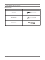
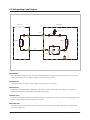
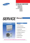
SYSTEM AIR CONDITIONER
INDOOR UNIT
OUTDOOR UNIT
Model :
ACN026NDEHA
ACN035NDEHA
ACN052NDEHA
ACN060NDEHA
ACN071NDEHA
NS0261DXEA
NS0351DXEA
Model code: ACN026NDEHA/EU
ACN035NDEHA/EU
ACN052NDEHA/EU
ACN060NDEHA/EU
ACN071NDEHA/EU
NS0261DXEA
NS0351DXEA
AIR CONDITIONER
RC026DHXEA
RC035DHXEA
RC052DHXEA
RC060DHXEA
RC071DHXEA
RC026DHXEA
RC035DHXEA
RC052DHXEA
RC060DHXEA
RC071DHXEA
CONTENTS
1. Precautions
2. Product Specifications
3. Disassembly and Reassembly
ACN026NDEHA
ACN035NDEHA
ACN052NDEHA
ACN060NDEHA
ACN071NDEHA
NS0261DXEA
NS0351DXEA
4. Troubleshooting
5. PCB Diagram
6. Wiring Diagram
7. Schematic Diagram
RC026DHXEA
RC035DHXEA
RC052DHXEA
RC060DHXEA
RC071DHXEA
8. Reference Sheet
Refer to the service manual in the GSPN(see the rear cover) for the more information.
Contents
11. Precautions ........................................................................................................................................ 1-1
1-1 Precautions for the Service ..............................................................................................................
1-1
1-2 Precautions related to static electricity and PL ............................................................................
1-1
1-3 Precautions related to product safety ...........................................................................................
1-2
1-4 Other precautions..............................................................................................................................
1-2
12. Product Specifications ............................................................................................................... 2-1
2-1 The Feature of Product .....................................................................................................................
2-2 Product Specifications ......................................................................................................................
2-1
2-2
2-3 Accessories..........................................................................................................................................
2-5
13. Disassembly and Reassembly ............................................................................................... 3-1
3-1 Indoor Unit .........................................................................................................................................
3-2 Outdoor Unit
.....................................................................................................................................
3-2
3-15
14. Troubleshooting ............................................................................................................................ 4-1
4-1 Setting an indoor unit address and installation option
............................................................
4-1
4-1-1 The procedure of setting option
.........................................................................................
4-1
4-1-2 The procedure of setting option
.........................................................................................
4-2
4-1-3 Setting an indoor unit address (MAIN/RMC) .....................................................................
4-4
4-1-4 Setting an indoor unit installation option (suitable for the condition of(each installation location) ....................
4-5
4-1-5 Changing a particular option ...............................................................................................
4-7
4-1-6 Option code for each model ................................................................................................
4-8
4-2 Items to check before diagnostics ................................................................................................. 4-11
4-2-1 Four directions cassette type ............................................................................................... 4-11
4-2-2 Test run mode and View mode
...........................................................................................
4-12
4-2-3 ECO mode(Power save) ......................................................................................................... 4-13
4-2-4 Slim 1 way cassette type ....................................................................................................... 4-14
4-2-5 Troubleshooting for outdoor unit ....................................................................................... 4-17
4-2-6 Wired remote controller
.......................................................................................................
4-18
4-3 Troubleshooting by symptoms ...................................................................................................... 4-20
4-3-1 Indoor temperature sensor (open/short)
..........................................................................
4-20
4-3-2 Indoor heat exchanger temperature sensor (open/short) ............................................. 4-21
4-3-3 Indoor FAN error ..................................................................................................................... 4-22
4-3-4 Communication error after finishing Tracking
.................................................................
4-23
4-3-5 Indoor unit float sensor error ............................................................................................... 4-24
4-3-6 EEPROM circuit failure ........................................................................................................... 4-25
4-3-7 Outdoor unit is not powered on
.........................................................................................
4-26
4-4 Troubleshooting by symptoms ............................................................................................................................... 4-28
..........................................................................................................
4-28
....................................................................................
4-29
4-4-3 Outdoor Coil temperature sensor error ..............................................................................................
4-31
.................................................................
4-33
.....................................................................
4-35
4-4-1 Communication error
4-4-2 Outdoor temperature sensor error
4-4-4 Outdoor Discharge temperature sensor error
4-4-5 Outdoor Discharge over temperature error
4-4-6 Outdoor Fan motor error .................................................................................................................... 4-36
4-4-7 Compressor starting error .................................................................................................................. 4-37
4-4-8 Compressor wire missing error/rotation error .......................................................................... 4-38
4-4-9 O.C(Over Current) error ....................................................................................................................... 4-39
4-4-10 DC_link voltage sensor error .......................................................................................................... 4-40
4-4-11 DC_link voltage under/over error, Over voltage protection error/PFC over load ..... 4-41
4-4-12 DC_link voltage sensor error ........................................................................................................... 4-42
4-4-13 Current sensor error/Input current sensor error .................................................................... 4-43
4-4-14 Heatsink sensor error/Heatsink over heat ................................................................................. 4-44
4-4-15 Comp Vlimit error/Comp current limit error ............................................................................ 4-45
4-4-16 EEPROM error/OTP error .................................................................................................................. 4-46
4-4-17 AC zero cross signal error ................................................................................................................. 4-47
4-4-18 Operation condition secession error............................................................................................ 4-48
4-4-19 Capacity miss match error ............................................................................................................... 4-49
4-4-20 Gas leak error ........................................................................................................................................ 4-50
4-4-21 MDS Error Flow chart ........................................................................................................................ 4-51
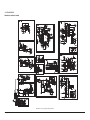
15. PCB Diagram ..................................................................................................................................... 5-1
5-1 PCB Diagram ......................................................................................................................................
5-1
5-1-1 MINI 4 WAY Indoor Unit ........................................................................................................
5-1
.................................................................................................................................
5-2
5-1-3 SLIM 1 WAY Indoor Unit ........................................................................................................
5-3
5-1-4 Outdoor Unit PCB ...................................................................................................................
5-4
5-1-2 Panel PCB
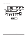
16. Wiring Diagram
6-1 Indoor Unit
..............................................................................................................................
6-1
........................................................................................................................................
6-1
....................................................................................................................................
6-3
6-2 Outdoor Unit
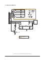
17. Schematic Diagram ...................................................................................................................... 7-1
7-1 Indoor Unit ...................................................................................................................................
7-1
7-2 Outdoor Unit ................................................................................................................................
7-5
8. Reference Sheet ............................................................................................................................. 8-1
8-1 Index for Model Name ......................................................................................................................
8-1
8-2 Refrigerating Cycle Diagram............................................................................................................
8-5
8-3 Pressure Graph ...................................................................................................................................
8-6
1. Precautions
1-1 Precautions for the Service
O Use the standard parts when replacing the electric parts.
– Confirm the model name, rated voltage, rated current of the electric parts.
O When repairing the equipment, connection of the harness parts must be firm and solid.
– A loose connection may cause noise or other malfunction.
O When assembling and disassembling the equipment while it is laid down, lay it on soft cloth.
– Otherwise it may scratch the back of the exterior of the product.
O Remove dust or dirt completely from the housing block, wiring block and service parts during repair.
– This helps prevent the danger of fire caused by tracking or short circuit.
O Fasten the valve caps of service valves and charging valves of outdoor unit as much as possible using adjustable wrenches.
O Check the status of the components’ assembly after repair service.
– The status must be the same as before the repair service.
1-2 Precautions related to static electricity and PL
O The PCB power supply block is susceptible to static electricity. Therefore, care must be taken during repair or measuring
while the power is on.
– Wear insulation gloves for PCB repair or measuring.
O Check whether the installation location is at least two meters away from other electronic products such as TV, video, or
audio.
– Otherwise, the video quality might be degraded or noise might be generated.
O Do not let end users repair the products themselves.
– Unauthorized disassembly might cause electric shock or fire.
Samsung Electronics
1-1
1-3 Precautions related to product safety
O Do not pull the power cord and do not touch the power plug or aux power switch with wet hands.
– It might cause electric shock or fire.
O A damaged power line or power plug must be replaced to prevent danger.
O Do not bend the power cable with excessive force, and do not place a heavy weight on the case as it might damage the
cable.
– It might cause electric shock or fire.
O Do not use multiple electric outlets.
– This might cause electric shock or fire.
O Connect the ground terminal when necessary.
– You must connect the ground terminal if you determine that there is a danger of electric leakage due to moisture or water.
O Unplug the power cable or turn off the auxiliary power switch for electric part replacement and repair service.
– Otherwise it might cause electric shock.
O Instruct end users to separate the batteries from the remote controllers and store them separately when the product is not
used for long time.
– Otherwise leakage from the dry cell may cause problems with the remote controller.
1-4 Other precautions
O The pipes should have no leaks during installation, and the compressor must be stopped before removing connecting
pipes for pump down work. Operating the compressor while the service valve is open and coolant pipe is not properly
connected may cause explosion or injury due to abnormal high pressure created inside the coolant cycle as the air can be
absorbed through the pipe.
O Pump Down work procedure (When uninstalling the product)
– Turn on the air conditioner, select cooling operation, and run the compressor for more than three minutes.
– Release the high pressure and low pressure valve caps.
– Close the high pressure valve completely using an L-wrench
– After about two minutes, close the low pressure valve completely.
– Stop running the air conditioner.
– Separate the connecting pipe.
1-2
Samsung Electronics
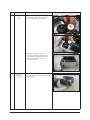
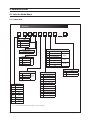
2. Product Specifications
2-1 The Feature of Product
Q Built-in Cassette Type
After installed, the air conditioner can be harmonized with a room interior.
Q High Performance & Energy Saving
With the advanced BLDC inverter technology, it makes a room cool with highly energy saving and arises the efficiency of air conditioner.
QLong Ambient Operation(In Low Temperature)
It can arise the reliability and the capacity of the air conditioner, especially operated in low temperature.
Q Eco-friendly Product(Lead-Free, RoHS, WEEE)
Q Easy installation of ultra-lightweight indoor unit
Samsung Electronics
2-1
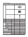
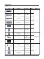
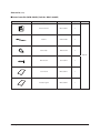
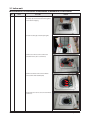
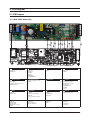
2-2 Product Specifications
ITEM
ACN060NDEHA/EU
RC060DHXEA
ACN071NDEHA/EU
RC071DHXEA
1Φ, 220~240V/50Hz
1Φ, 220~240V/50Hz
Indoor Unit
Outdoor Unit
IMAGE
Remote Controller
Power
Product
Indoor
LxHxD
mm
575*250*575
575*250*575
Panel
LxHxD
mm
670*45*670
670*45*670
Outdoor
LxHxD
mm
798 x 880 x 310
798 x 880 x 310
Indoor
Product
kg(Net)
12.0
12.0
Outdoor
Product
kg(Net)
54.5
54.5
Cooling(STD)
W
5800
6800
Heating(STD)
W
7000
7500
Capacity
Power
Consumption
Operation
current
Noise
(Cooling/
Heating)
Cooling(STD)
W
1809
2120
Heating(STD)
W
2180
2340
Cooling(STD)
A
8.3
9.7
Heating(STD)
A
10
10.7
dBA
45/46
46/46
dBA
60/60
60/60
In case of strongest air
Indoor unit
blow
In case of strongest air
Outdoor unit
blow
Refrigerant(R410A)
g
1,800
1,800
Liquid
mm
6.35
6.35
Gas
mm
15.88
15.88
Additional Refrigerant (R410A)
g/m
25
25
Standard
m
5
5
Extension length(Total)
m
50
50
Extension length(Elevation)
m
30
30
Connecting Pipe
Option Code
2-2
Product Option
015077-18626E-273C46-370040
015077-166381-274750-370040
Installation Option
020000-100000-200000-300000
020000-100000-200000-300000
Samsung Electronics
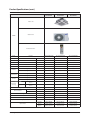
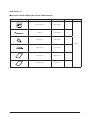
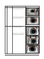
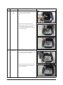
Product Specifications (cont.)
ITEM
ACN026NDEHA/EU
RC026DHXEA
ACN035NDEHA/EU
RC035DHXEA
ACN052NDEHA/EU
RC052DHXEA
1Φ, 220-240V/50Hz
1Φ, 220-240V/50Hz
1Φ, 220-240V/50Hz
Indoor Unit
Outdoor Unit
IMAGE
Remote Controller
Power
Product
Indoor
LxHxD
mm
575*250*575
575*250*575
575*250*575
Panel
LxHxD
mm
670*45*670
670*45*670
670*45*670
Outdoor
LxHxD
mm
790*285*545
790*285*545
790*285*545
Indoor
Product
kg(Net)
11.0
11.0
11.7
Outdoor
Product
kg(Net)
33.0
33.0
38.5
Cooling(STD)
W
2600
3500
5000
Heating(STD)
W
3300
4000
5500
Power
Consumption
Cooling(STD)
W
730
1090
1560
Heating(STD)
W
900
1110
1525
Operation
current
Cooling(STD)
A
3.7
5.6
7.2
Heating(STD)
A
4.6
5.7
7
dBA
38/39
41/42
43/44
dBA
51/51
53/53
58/58
g
950
950
3,800
mm
6.35
6.35
6.35
Capacity
Noise
(Cooling/
Heating)
In case of strongest air
blow
In case of strongest air
Outdoor unit
blow
Indoor unit
Refrigerant (R410A)
Connecting Pipe
Liquid
mm
9.53
9.53
12.7
Additional Refrigerant (R410A)
Gas
g/m
-
-
-
Standard
m
5
5
5
Extension length(Total)
m
20
15
20
Extension length(Elevation)
m
15
20
30
Option Code
Product
Option
Installation
Option
015077-1660F8271A21-370000
020000-100000200000-300000
015077-166219272328-370000
020000-100000200000-300000
015077-17625D273437-370040
020000-100000200000-300000
Samsung Electronics
2-3
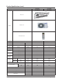
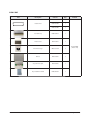
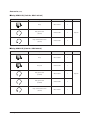
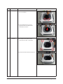
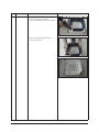
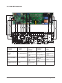
Product Specifications (cont.)
ITEM
NS0261DXEA
RC026DHXEA
NS0351DXEA
RC035DHXEA
1Φ, 220~240V/50Hz
1Φ, 220~240V/50Hz
Indoor Unit
Outdoor Unit
IMAGE
Remote Controller
Power
Product
Indoor
LxHxD
mm
975*135*410
975*135*410
Panel
LxHxD
mm
1180*25*460
1180*25*460
Outdoor
LxHxD
mm
790*548*285
790*548*285
Indoor
Product
kg(Net)
10.0
10.0
Outdoor
Product
kg(Net)
33.0
33.0
Capacity
Cooling(STD)
W
2600
3500
Heating(STD)
W
3300
4000
Power
Consumption
Cooling(STD)
W
695
1140
Heating(STD)
W
910
1160
Operation
current
Cooling(STD)
A
3.3
3.3
Heating(STD)
A
5.3
5.5
dBA
38/40
40/42
dBA
51/51
53/53
g
950
950
mm
6.35
6.35
Noise
(Cooling/
Heating)
In case of strongest air
blow
In case of strongest air
Outdoor unit
blow
Indoor unit
Refrigerant(R410A)
Connecting Pipe
mm
9.52
9.52
Additional Refrigerant (R410A)
g/m
20
20
Standard
m
5
5
Extension length(Total)
m
20
20
Extension length(Elevation)
m
15
15
Product Option
017057-1860F8-271A23-370010
017057-17624D-272328-370010
Installation Option
020000-100000-200000-300000
020000-100000-200000-300000
Option Code
2-4
Liquid
Gas
Samsung Electronics
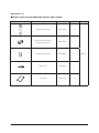
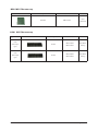
2-3 Accessories
MINI 4 WAY
Item
Description
Code No.
Q’ty
Ass'y drain hose
DB94-03287A
1
Cable-tie
DB65-10088C
6
Seal-drain ass'y
DB62-11028A
1
Remark
Essential Offer
(Indoor Unit)
Samsung Electronics
Seal-drain ass'y
DB62-11028H
1
Seal-drain ass'y
DB62-11028J
1
ASSY INSTALL MANUAL/USER MANUAL
DB98-34365A
DB98-34366A
1/1
ASSY-INSTALLATION
MANUAL
DB98-34367A
1
Drain Plug
DB6700477A(026/035/052)
DB67-20011A(060/071)
1
Rubber Leg
DB73-20134A
4
BOLT
6011-003975
4
ASSY-INSTALLATION
MANUAL
DB98-34364A
1
CARD WARRNATY
DB68-02596B
1
Essential Offer (Outdoor
Unit)
Essential Offer
(Panel)
2-5
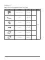
SLIM 1 WAY
Item
Description
Code No.
Q’ty
DB69-01936A
1
DB69-01947A
1
DB69-01947B
1
Seal-drain ass'y
DB62-05810A
1
Insulation-base
DB72-00401C
2
Pattern sheet
2-6
Grommet hanger
DB63-00237A
8
Cable tie
DB65-10088C
3
Ass'y drain hose joint
DB94-01258C
1
Ass'y-installation manual
DB98-34507A
1
Remark
Essential Offer
(Indoor Unit)
Samsung Electronics
Accessories (cont.)
Q Wireless remote controller (MR-DH00) [Code No. : DB97-17546B]
Item
Samsung Electronics
Descriptions
Code-No.
Q'TY
Wireless remote controller
DB93-11115N
1
Batteries for remote controller
(specification: "AAA" type)
DB47-90024A
2
Remote controller holder
DB61-04899A
1
M4×16 screw
6002-000581
2
User’s manual
DB98-33129A
1
Remark
Optional
2-7
Accessories (cont.)
Q Wired remote controller (MWR-WE10) [Code No. : DB97-17002B]
Item
Descriptions
Code-No.
Q'TY
Wired remote controller
DB93-11251B
1
Cable tie
DB65-10088B
2
Cable clamp
DB65-10074E
3
Remark
Optional
2-8
M4×16 Screw
6002-000474
5
User’s manual
DB98-32810A
1
Installation guide
DB98-32811A
1
Samsung Electronics
Accessories (cont.)
Q Central controller (MCM-A202D) [Code No. : DB97-18602B]
Item
Descriptions
Code-No.
Q'TY
Central controller
DB93-03425N
1
Cable tie
DB65-10088B
2
Cable clamp
DB65-10074E
5
Remark
Optional
Samsung Electronics
M4 X 16 Screw
6002-000474
7
User’s manual
DB98-33437A
1
Installation guide
DB98-33434A
1
2-9
Accessories (cont.)
Q Function controller (MCM-A100) [Code No. : DB97-01077A]
Item
Descriptions
Code-No.
Q'TY
Function controller
DB93-00757G
1
Cable tie
DB65-10088B
2
Cable clamp
DB65-10074E
6
Remark
Optional
M4×16 Screw
6002-000474
7
User’s manual
DB98-27317A
1
Installation guide
DB98-27315A
1
* PC control and DMS cannot be used when using the function controller
2-10
Samsung Electronics
Accessories (cont.)
Q Relay (MIM-B13D) [Code No. : DB97-18519A]
Item
Descriptions
Code-No.
Q'TY
Relay
DB93-12203A
1
Relay power cable
(300mm)
DB39-00378B
1
Relay communication cable
(300mm)
DB39-00253B
1
Descriptions
Code-No.
Q'TY
Relay
DB93-03568D
1
Relay sub
DB93-03590B
1
Relay power cable
(1,000mm)
DB93-07895A
1
Relay power cable
(1,000mm)
DB93-07895B
1
Relay communication cable
(100mm)
DB93-12164A
1
Remark
Optional
Q Relay (MIM-B13E) [Code No. : DB97-04416J)
Item
Samsung Electronics
Remark
Optional
2-11
MINI 4 WAY Filter accessory
Item
Descriptions
Code-No.
Dust filter
DB63-02739A
Remark
Basic/
Water wash
SLIM 1 WAY Filter accessory
Item
Type
Descriptions
Panel
(Slim 1way-A
Air Filter
type)
Panel
(Slim 1way-B
type)
2-12
Air Filter
Code-No.
Remark
DB63-01694A
Basic/Water
DB63-01695A
washing
DB63-02354A
Basic/Water
DB63-02355A
washing
Samsung Electronics
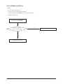
3. Disassembly and Reassembly
QNecessary Tools
Item
Remarks
+SCREW DRIVER
Adjustable Wrench
(8mm, 10mm, 13mm)
M6, M8 Hex Wrench
Samsung Electronics
3-1
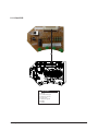
3-1 Indoor unit
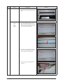
QACN026NDEHA/ ACN035NDEHA/ ACN052NDEHA/ ACN060NDEHA/ ACN071NDEHA
No
Parts
Procedure
1
Panel
1) Pull both hooks and take the grille downward.
Two safety clips are mounted to the front grille to
prevent it from dropping.
Remark
2) Detach the safity clip and take up the grille.
3) Remove the 2 fixed screws to remove the
Control-Box Cover. (Use +Screw Driver)
4) Remove the Remocon-Receiver and Blade
Connector Wire from the PBA. (3EA)
5) Push the 4 panel corners and cover downwards
to remove it.
3-2
Samsung Electronics
No
Parts
Procedure
Remark
6) Disassemble the bolts that are assembled
with the indoor unit at the 4 panel corners.
7) Press the Hangers at both sides of the panel
inwards, to remove it from the indoor unit’s hook.
Remove the panel from the indoor unit.
2
Control-Box
1) Disconnect the Connector Wire that is
connected to the indoor unit’s PBA
2) Unscrew the 2 fixed screws on both sides of
the Control Box, and disassemble the Control Box
from the indoor unit.(Use +Screw Driver)
Samsung Electronics
3-3
No
Parts
3
Bell-Mouth
Procedure
Remark
1) Unscrew the screw fixed on the Bell-Mouth.
(Use +Screw Driver)
2) Push the Bell-Mouth in the direction
opposite to where it’s installed on the
Control-Box to remove it.
4
Drain Pan
1) Unscrew the screws on the 4 corners
of the indoor unit. (Use +Screw Driver)
2) Remove the Drain Pan from the indoor unit.
3-4
Samsung Electronics
No
Parts
5
Drain Pump
&
Hose
Procedure
Remark
1) Remove the 2 fixed screws and
disconnect the white drainage hose from
the Drain Pump. (Use +Screw Driver)
2) Remove the 2 screws and take the
Drain-Hose out from the indoor unit to
disassemble the transparent Drain-Hose
fixed on the side of the indoor unit.
(Use +Screw Driver)
6
Evap.
Temperature
Sensor
Samsung Electronics
1) Use your hand to remove the temperature
sensor attached to the Evap Pipe along with
the fixing clip.
3-5
No
Parts
Procedure
7
Fan
&
Motor
1) Turn the hexangular nut attached to the
top of the Fan counterclockwise to remove it.
Take the Fan out of the Motor.
Remark
2) Turn the three hexangular nuts on the
Motor counterclockwise to remove the nuts.
Take the Motor Wires attached to these
three locations out with your hands prior to
removing the Motor.
8
Evaporator
1) Remove the screws of the Steel Holder Evaps
that are used to fix the Heat Exchanger, and
then remove it. (Use +Screw Driver)
2) Remove the 2 fixing screws of the Partition
Evap at the Heat Exchanger’s In/Out Pipe.
(Use +Screw Driver)
3-6
Samsung Electronics
No
Parts
Procedure
Remark
3) Remove the screw of the Cover Pipe
that is used to fix the In/Out Pipe.
Remove the In/Out Pipe. (Use +Screw Driver)
4) Remove the Heat Exchanger from the
indoor unit’s cabinet.
Samsung Electronics
3-7
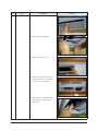
QNS0261DXEA/ NS0351DXEA
No
Parts
1
Panel
&
Procedure
Remark
1) Press the push button on the Grille to
open.
Filter(A type)
2) Separate 1 clip from the Panel then tilt
the Grille 45° to remove Grille from the
Panel.
3) Separate Filter from the Panel.
4) Separate 3 cover screws from it.
5) Undo 6 fixed screws on the Panel
to remove from the Indoor Unit.
(Use +Screw Driver.)
3-8
Samsung Electronics
No
Parts
Procedure
Remark
6) Press the left and right hooks on the
Panel to separate Panel from the Indoor
Unit.
Panel
&
Filter
(B type)
1) Press the [Filter Reset] button on the
Wireless Remote Controller once. It will
make an induction Panel that is shown
in the next picture slide down.
2) Spin the 2 connecting levers that link
both ends of the induction Panel and
gear as shown in the next picture.
3) Push the induction Panel forward to
remove it.
Samsung Electronics
3-9
No
Parts
Procedure
Remark
4) Remove the induction Filter. (2EA)
5) Remove the Filter Guide. (2EA)
6) Remove the 3 screws covers.
7) Remove 4 connecting wires for the
Panel and undo the 7 screws that fix
the Panel. (Use + Screw Driver.)
8) After pulling out 2 Panel fixing hooks,
please separate the Panel and the
Indoor Unit.
3-10
Samsung Electronics
No
Parts
2
Drain Pan
Procedure
Remark
1) Separate 5 fixing screws in the Drain
Pan. (Use +Screw Driver.)
2) Pull the Drain Pan to separate it from
the Indoor Unit.
When separating the Pan please be
careful not to touch the board of Heat
Exchanger.
3
Control In
Samsung Electronics
1) Undo 3 fixing screws in the Control In
appliance part to separate the Cover.
(Use +Screw Driver.)
3-11
No
Parts
Procedure
Remark
2) Separate 8 connecters on the PCB of the
Indoor Unit.
3) Separate the Control In from the Indoor
Unit.
4
3-12
Drain Sub
1) Push the hook on the Drain Sub to
separate it.
Samsung Electronics
No
Parts
5
Heat Exchanger
Procedure
Remark
1) Undo fixing screw in the Heat
Exchanger. (Use +Screw Driver.)
2) Separate the Indoor Unit’s Sensor from
the Heat Exchanger.
3) Separate the Heat Exchanger from
the Indoor Unit.
6
Cross Fan
1) Undo 3 fixing screws on the Cover
Fan Motor. (Use +Screw Driver.)
2) Separate the Cover Fan Motor from
the Indoor Unit. (Use +Screw Driver.)
Samsung Electronics
3-13
No
Parts
Procedure
Remark
3) Separate the Cross Fan from the Indoor
Unit.
7
Drain Pump
1) Separate fixing screw in the Cover Drain
Pump. (Use +Screw Driver.)
2) Separate the Drain Hose from the
Drain Pump.
3) Separate the Drain Pump from the
Indoor Unit.
3-14
Samsung Electronics
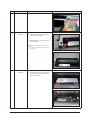
3-2 Outdoor Unit
QRC060DHXEA /RC071DHXEA
No
Parts
Procedure
1
Common Work
1) Loosen 1 fixing screw of the Cover-Control
and detach the Cover Control.
Remark
2) Loosen each 7 fixing screws and detach
the Cabinet Upper.
Samsung Electronics
3-15
No
Parts
Procedure
Remark
3) Loosen 2 screws fixed to assemble
Control Box with Cabinet-Side RH.
4) Loosen fixing screws and detach the
Cabinet-Side RH.
5) Loosen 2 screws fixed on the Guide
Condenser.
3-16
Samsung Electronics
No
Parts
Procedure
Remark
6) Loosen fixing screws of the Cabinet Front.
Samsung Electronics
3-17
No
Parts
2
Fan
&
Motor
Procedure
Remark
1) Detach the Nut Flange like the picture on
the right side. (Turn counter clockwise
because the screw is right-handed.)
2) Detach the Fan Propeller.
3) Loosen 4 fixing screws to detach the Motor.
4) Disconnect the wire between ASS'Y
Control Out and Motor.
5) Loosen 2 fixing bolts and detach the
Bracket Motor.
3-18
Samsung Electronics
No
Parts
Procedure
3
ASS'Y Control Out
1) Detach several connectors from the
ASS'Y Control Out.
2) Detach several connectors from the PCB
of ASS'Y Control Out.
3) Pull up the ASS'Y Control Out.
4
Heat Exchanger
1) Release the refrigerant at first.
2) Loosen fixing screw on both sides.
3) Disassemble the pipes in both inlet and
outlet with welding torch.
4) Detach the Heat Exchanger.
Remark
5) Loosen 4 bolts fixed to assemble Valve
Service with Bracket Valve like the picture
on the right side.
Samsung Electronics
3-19
No
Parts
5
Compressor
Procedure
Remark
1) Loosen the fixing nut and detach the
Compressor Lead Wire.
2) Disassemble the Felt Compressor Sound.
3) Loosen the 3 bolts at the bottom of
Compressor like the picture on the
right side.
3-20
Samsung Electronics
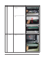
QRC026DHXEA/ RC035DHXEA/ RC052DHXEA
No
Parts
Procedure
1
common work
1) loosen 1 pcs screw of cover control,and
detach it.
Remark
2) loosen 5 pcs screws on both right and
left cabniet side edges and to detach the
cover-top
3) Loosen 7 screwsfixed to disassemble
cabi-front , and detach it.
Samsung Electronics
3-21
No
Parts
common work
Procedure
Remark
4) loosen 7 screws to disassemble the cabiright ,and detach it.
5) loosen 2 screws to disassemble steel-bar.
6) loosen 3 screws to disassemble cabi-left.
3-22
Samsung Electronics
No
Parts
Procedure
2
fan&motor
1) loosen 1 screw as indication and detached
the fan.
Remark
2) loosen 4 pcs motor screws and disconnect
the wire betwwen assy control out and motor.
3) loosen 2 pcs bracket-motor screw and
detach it.
Samsung Electronics
3-23
No
Parts
3
assy control out
1) lossen fixing 1 screw from cover -control
2) detach several connections from assy control out, take out assy control out.
4
Heat exchanger
1) Release the refrigerant at first
2) Looosen fixing screw on both side.
3) disaessembly the pipes in both inlet and
outlet with welding torch.
4) detach the heat exchanger.
3-24
Procedure
Remark
Samsung Electronics
No
Parts
5
compressor
Procedure
Remark
1) disconnect the compressor lead wire .
2)disassembly the felt comp sound.
loosen the 3 bolts at the bottom of
Samsung Electronics
3-25
4. Troubleshooting
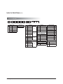
4-1 Setting an indoor unit address and installation option
▶ Set the indoor unit address and installation option with remote controller option.
Set the each option separately since you cannot set the ADDRESS setting and indoor unit installation setting option at the
same time.You need to set twice when setting indoor unit address and installation option.
▶ Please use the proper wireless remocon which can set 24 digit option code. Following is the instructions of setting option
code with wireless remocon of MR-DH00. (MR-AH01 can be used for operating but cannot be used for setting the installation
option because only 12 digit option setting is available.
▶ Please refer to the wired remocon installation manual for setting with the wired remocon.
4-1-1 The procedure of setting option
Entering mode for
setting option
Option setting mode
Mode change
High Temp Button
High Fan Button
Low Temp Button
Low Fan Button
Step 1. Entering mode to set option
1. Remove batteries from the remote controller.
2. Insert batteries and enter the option setting mode while pressing High Temp button and Low Temp button.
3.
Check if you have entered the option setting status.
Step 2. The procedure of option setting
After entering the option setting status, select the option as listed below.
Option setting is available from SEG1 to SEG 24
t 4&(4&(4&(4&(BSFOPUOFFEUPCFTFUBU.3%)5IFZBSFUIFQBHFPQUJPOTXIJDIXFSFVTFEBUUIF
previous other remocons.
t 4FUUIFFBDICJUPQUJPODPEFJOPSEFSFYDFQUQBHFPQUJPOT
For example : SEG2, 3 SEG4, 5 SEG6, 8 SEG9, 10 SEG11, 12 SEG 14, 15 SEG 16, 17 SEG 18, 20
SEG 21, 22 SEG23, 24.
SEG1 SEG2 SEG3 SEG4 SEG5 SEG6 SEG7 SEG8 SEG9 SEG10 SEG11 SEG12
0
X
X
X
X
X
1
X
X
X
X
X
SEG13 SEG14 SEG15 SEG16 SEG17 SEG18 SEG19 SEG20 SEG21 SEG22 SEG23 SEG24
2
X
X
X
X
X
3
X
X
X
X
X
4-1
On(SEG1~12)
Off(SEG13~24)
Samsung Electronics
4-1-2 The procedure of setting option
Option setting
1. Setting SEG2, SEG3 option
Press Low Fan button(∨) to enter SEG2 value.
Press High Fan button(∧) to enter SEG3 value.
Each time you press the button,
…
will be selected in rotation.
Status
SEG2
SEG3
SEG4
SEG5
SEG6
SEG8
SEG9
SEG10
SEG11
SEG12
SEG14
SEG15
2. Setting Cool mode
Press Mode button to be changed to Cool mode in the ON status.
3. Setting SEG4, SEG5 option
Press Low Fan button(∨) to enter SEG4 value.
Press High Fan button(∧) to enter SEG5 value.
…
Each time you press the button,
will be selected in rotation.
4. Setting Dry mode
Press Mode button to be changed to DRY mode in the ON status.
5. Setting SEG6, SEG8 option
Press Low Fan button(∨) to enter SEG6 value.
Press High Fan button(∧) to enter SEG8 value.
Each time you press the button,
…
will be selected in rotation.
6. Setting Fan mode
Press Mode button to be changed to FAN mode in the ON status.
7. Setting SEG9, SEG10 option
Press Low Fan button(∨) to enter SEG9 value.
Press High Fan button(∧) to enter SEG10 value.
…
will be selected in rotation.
Each time you press the button,
8. Setting Heat mode
Press Mode button to be changed to HEAT mode in the ON status.
9. Setting SEG11, SEG12 option
Press Low Fan button(∨) to enter SEG11 value.
Press High Fan button(∧) to enter SEG12 value.
Each time you press the button,
…
will be selected in rotation.
10. Setting Auto mode
Press Mode button to be changed to AUTO mode in the OFF status.
11. Setting SEG14, SEG15 option
Press Low Fan button(∨) to enter SEG14 value.
Press High Fan button(∧) to enter SEG15 value.
Each time you press the button,
…
will be selected in rotation.
Samsung Electronics
4-2
The procedure of setting option (cont.)
Option setting
Status
12. Setting Cool mode
Press Mode button to be change to Cool mode in the OFF status.
13. Setting SEG16, SEG17 option
Press Low Fan button(∨) to enter SEG16 value.
Press High Fan button(∧) to enter SEG17 value.
Each time you press the button,
…
will be selected in rotation.
SEG16
SEG17
SEG18
SEG20
SEG21
SEG22
SEG23
SEG24
14. Setting Dry mode
Press Mode button to be change to Dry mode in the OFF status.
15. Setting SEG18, SEG20 option
Press Low Fan button(∨) to enter SEG18 value.
Press High Fan button(∧) to enter SEG20 value.
…
will be selected in rotation.
Each time you press the button,
16. Setting Fan mode
Press Mode button to be change to Fan mode in the OFF status.
17. Setting SEG21, SEG22 option
Press Low Fan button(∨) to enter SEG21 value.
Press High Fan button(∧) to enter SEG22 value.
…
will be selected in rotation.
Each time you press the button,
18. Setting Heat mode
Press Mode button to be change to HEAT mode in the OFF status.
19. Setting SEG23, SEG24 mode
Press Low Fan button(∨) to enter SEG23 value.
Press High Fan button(∧) to enter SEG24 value.
Each time you press the button,
…
will be selected in rotation.
Step 3. Check the option you have set
After setting option, press
Option
button to check whether the option code you input is correct or not.
[SEG2,3]
[SEG4,5]
[SEG6,8]
[SEG9,10]
[SEG11,12]
[SEG14,15]
[SEG16,17]
[SEG18,20]
[SEG21,22]
[SEG23,24]
Remote Controller Display
Option
Remote Controller Display
Step 4. Input option
Press operation button
with the direction of remote control for set.
For the correct option setting, you must input the option twice.
Step 5. Check operation
1. Reset the indoor unit by pressing the RESET button of indoor unit or outdoor unit.
2. Take the batteries out of the remote controller and insert them again and then press the operation button.
4-3
Samsung Electronics
4-1-3 Setting an indoor unit address (MAIN/RMC)
1. Check whether power is supplied or not.
- When the indoor unit is not plugged in, there should be additional power supply in the indoor unit.
2. The panel(display ) should be connected to an indoor unit to receive option.
3. Before installing the indoor unit, assign an address to the indoor unit according to the air conditioning system plan.
4. Assign an indoor unit address by wireless remote controller.
-The initial indoor unit ADDRESS is set as "MAIN : 0, RMC : 0".
-Set Main and RMC Address only the setting is required.
-There is no need to assign the indoor unit Main Address if the outdoor unit is addressing automatically.
The indoor unit Main address will follow the outdoor unit's automatically.
-Assign 12 digit when setting the indoor unit address.
-No need to assign SEG4, 5, 8, 10 which are non applicable. Even though those segments are set, they will be ignored.
-If you set the applicable segments with numbers other than the indiciated, the initial setting will be maintained.
Option No. : 0AXXXX-1XXXXX-2XXXXX-3XXXXX
Option
SEG1
SEG2
SEG3
Explanation
PAGE
MODE
Setting Main address
Indication Details Indication Details
Indication
and Details
0
Option
SEG7
Explanation
PAGE
Details
0
No Main
address
1
Main address
setting mode
A
SEG8
SEG9
RESERVED
Indication
Details
0
No RMC address
1
RMC address
setting mode
1
SEG5
SEG6
The unit digit of
an indoor unit
Indication Details
RESERVED
RESERVED
0~3
SEG10
Setting RMC address
Indication Details
Indication
and Details
Indication
SEG4
A single
digit
SEG11
SEG12
Group
channel(*16)
Group address
Indication Details Indication Details
RESERVED
RMC1
0~2
RMC2
0~F
t8IFOi"w_w'wJTFOUFSFEUP4&(_UIFJOEPPSVOJU."*/"%%3&44JTOPUDIBOHFE
t*GZPVTFUUIF4&(BTUIFJOEPPSVOJUXJMMNBJOUBJOUIFQSFWJPVT."*/"%%3&44FWFOJGZPVJOQVUUIFPQUJPOWBMVFPG4&(
t*GZPVTFUUIF4&(BTUIFJOEPPSVOJUXJMMNBJOUBJOQSFWJPVT3.$"%%3&44FWFOJGZPVJOQVUUIFPQUJPOWBMVFPG4&(_
Example) If you want to set as "MAIN : 3, CHANNEL : 1, RMC : B",
SEG1
SEG2
SEG3
SEG4
0
A
1
SEG7
SEG8
SEG9
SEG10
1
1
assign option codes except SEG 1, 7 which are page options.
Samsung Electronics
SEG5
SEG11
1
SEG6
3
SEG12
B
4-4
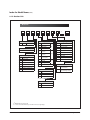
4-1-4 Setting an indoor unit installation option (suitable for the condition of each installation location)
1. Check whether power is supplied or not.
- When the indoor unit is not plugged in, there should be additional power supply in the indoor unit.
2. The panel(display ) should be connected to an indoor unit to receive option.
3. Set the installation option according to the installation condition of an air conditioner.
- The default setting of an indoor unit installation option is “02000-100000-200000-300000”.
- Individual control of a remote controller(SEG20) is the function that controls an indoor unit individually when there is
more than one indoor unit.
- No need to assign SEG3, 6, 9, 10, 11, 16, 21, 22, 23, 24 which are non applicable. Even though those segments are set,
they will be ignored.
- If you set the applicable segments with numbers other than the indiciated, the initial setting will be maintained.
4. Set the indoor unit option by wireless remote controller.
Option No. : 02XXXX-1XXXXX-2XXXXX-3XXXXX
Option
SEG1
SEG2
Explanation
PAGE
MODE
Indication Indication Details Indication Details
and
0
2
Details
Option
SEG7
SEG8
Explanation
PAGE
Use of drain
pump
SEG3
RESERVED
SEG9
SEG4
SEG5
SEG6
(Mini 4Way only)
Use of external
temperature sensor
Use of central
control
RPM setting
compensation
Indication Details Indication Details
0
Disuse
0
Disuse
1
Use
1
Use
SEG10
SEG11
0. Not used
1. High ceiling mode
2. High ceiling kit
3. Low noise operation
mode
SEG12
Master / Slave
Indication Details Indication Details
Indication Details
RESERVED
RESERVED
RESERVED
0
Disuse
0
slave
Indication
1
Use
1
master
and
1
Details
Use +
2
3minute
delay
Option
SEG13
SEG14
SEG15
SEG16
SEG17
SEG18
Use
of
external
Setting
the
output
Number
of hours
S-Plasma ion
Buzzer control
Explanation
PAGE
control
of external control
using filter
Indication Details Indication Details Indication Details Indication Details Indication Details Indication Details
Thermo
0
Disuse
0
0
Disuse
0
Use of buzzer
2
1000 Hour
on
ON/OFF
Indication
1
Control
and
OFF
2
Details
2
Operation
Non use
2000
Control
1
1
Use
1
6
on
of buzzer
Hour
WINDOR
3
ON/OFF
4-5
Samsung Electronics
Option
Explanation
Indication
and
Details
SEG19
SEG20
Individual control of
a remote controller
Indication Details Indication Details
0 or 1 Indoor 1
2
Indoor 2
3
Indoor 3
SEG22
SEG23
(Mini 4 Way only)
SEG24
RESERVED
Motion detect
sensor
Indication Details
0.No Use (Factory Setting)
1.Standard Mode/Auto
Set OFF30 Min.
2.Standard Mode/Auto
Set OFF60 Min.
3.Standard Mode/Auto
Set OFF 120 Min.
4.Standard Mode/Auto
Set OFF 180 Min.
5.Premium Mode/
Auto Set OFF30
Min.6.Premium Mode/
Auto Set OFF60 Min.
7.Premium Mode/Auto
Set OFF 120 Min.
8.Premium Mode/Auto
Set OFF 180 Min.
RESERVED
SEG21
PAGE
3
4
0
Disuse
1
2˚C
2
5˚C
Indoor 4
X If you input a number other than 0~4 on the individual control of the indoor unit(SEG 20), the indoor is
set as "Indoor 1".
Example) If you want to set as "Exterior temperature sensor : USE, External control : USE, Number of hours
using filer : 2000hr",
SEG1
SEG2
SEG3
SEG4
0
2
1
SEG7
SEG8
SEG9
SEG10
1
0
SEG13
SEG14
SEG15
SEG16
2
1
0
SEG19
SEG20
SEG21
SEG22
3
0
assign option codes except SEG 1, 7, 13, 19 which are page options.
Samsung Electronics
SEG5
0
SEG11
SEG17
0
SEG23
-
SEG6
SEG12
0
SEG18
6
SEG24
-
4-6
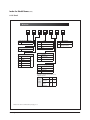
4-1-5 Changing a particular option
You can change each digit of set option.
Option
SEG1
SEG2
Explanation
PAGE
MODE
Indication
and
Details
Indication Details Indication
0
Details
D
SEG3
SEG4
SEG5
SEG6
The option mode The tens’ digit of an The unit digit of
you want to
option SEG you will an option SEG you The changed value
change
change
will change
Indication Details Indication Details Indication Details Indication Details
The
Option
Tens’ digit
Unit digit
0~F
0~9
0~9 changed 0~F
mode
of SEG
of SEG
value
t 8IFODIBOHJOHBEJHJUPGBOJOEPPSVOJUBEESFTTTFUUJOHPQUJPOTFUUIF4&(BTA"
t 8IFODIBOHJOHBEJHJUPGJOEPPSVOJUJOTUBMMBUJPOPQUJPOTFUUIF4&(BTA
Ex) When setting the 'buzzer control' into disuse status.
4-7
Option
SEG1
SEG2
Explanation
PAGE
MODE
Indication
0
D
SEG3
SEG4
SEG5
SEG6
The option The tens’ digit of The unit digit of
mode you want an option SEG an option SEG
to change
you will change you will change
2
1
7
The changed
value
1
Samsung Electronics
4-1-6 Option code for each model
Model
OPTION CODE
ACN026NDEHA
015077-1660F8-271A21-370000
ACN035NDEHA
015077-166219-272328-370000
ACN052NDEHA
015077-17625D-273437-370040
ACN060NDEHA
015077-18626E-273C46-370040
ACN071NDEHA
015077-156391-274750-370040
NS0261DXEA
017057-1860F8-271A23-370010
NS0351DXEA
017057-17624D-272328-370010
Samsung Electronics
4-8
4-2 Items to check before diagnostics
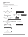
4-2-1 Four directions cassette type
Error Mode
Product operation with error
Cause
Operation
Outdoor
heat exchanger fan
Indoor
heat exchanger fan
Diagnosis method
Timer
Filter
X
X
X
Power reset
-
operation-off
operation-off
operation-off
-
X
X
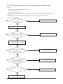
Error of room temperature sensor in the indoor
unit (Open/Short)
t$IFDLJOEPPSUFNQFSBUVSFTFOTPSDPOOFDUJPO
t$IFDLJOEPPSUFNQFSBUVSFTFOTPSTSFTJTUBODFWBMVFUPTFFJGJUTTIPSUPQFO
operation-off
operation-off
operation-off
page 4-17
X
X
Error of heat exchanger IN/OUT sensor in the
indoor unit (Open/Short)
t$IFDL&7"*/065TFOTPSDPOOFDUJPO
t$IFDL&7"*/065TFOTPSTSFTJTUBODFWBMVFUPTFFJGJUTTIPSUPQFO
operation-off
operation-off
operation-off
page 4-18
X
X
Error of fan motor in the indoor unit
t$IFDLUIFDPOOFDUJPOPGNPUPSDPOOFDUPS
t$IFDLUIFTQFFEPGUIFNPUPSGBO
operation-off
operation-off
operation-off
page 4-19
X
X
Error of the outdoor temperature sensor
Error of the condensor temperature sensor
Error of the discharge temperature sensor
t$IFDLJOEPPSUFNQFSBUVSFTFOTPSDPOOFDUJPO
t$IFDLJOEPPSUFNQFSBUVSFTFOTPSTSFTJTUBODFWBMVFUPTFFJGJUTTIPSUPQFO
operation-off
operation-off
operation-off
-
X
No communication for 2 minutes between indoor
and outdoor unit (communication error for more
than 2 minutes)
t$IFDLDPOOFDUJPOCFUXFFOJOEPPSBOEPVUEPPSIFBUFYDIBOHFSTDPNNVOJDBUJPO
cables
operation-off
operation-off
operation-off
page 4-20
Error of outdoor unit
t$IFDLFSSPSPDDVSSFEXJUIPVUEPPSIFBUFYDIBOHFS
operation-off
operation-off
operation-off
-
Detection of the float switch
t$IFDLGMPBUTXJUDIDPOOFDUJPO
t$IFDLXIFUIFSUIFESBJOIBTCFFOGJMMFEXJUIXBUFS
operation-off
operation-off
operation-off
page 4-21
EEPROM error
t$IFDLJGUIFSFJTEBNBHFXJUI&&130.DPNQPOFOU
operation-off
operation-off
operation-off
page 4-22
EEPROM option error
t$IFDLUIFJOEPPSNPEFMUPTFUUIFPQUJPOT
t*OTQFDUJPOGPSNBUDICFUXFFOJOEPPSBOEPVUEPPSNBDIJOFNPEFMT
operation-off
operation-off
operation-off
-
.%4LJUFSSPS
$IFDLUIFXJSFDPOOFDUJPO
$IFDLUIF.%4,*5
$IFDLUIFJOEPPS1#"
operation-on
operation-on
operation-on
page 4-49
X
X
X
Outdoor
heat exchanger
compressor
Defrost
X
X
Measures
X
X
X
X
: On
Samsung Electronics
: #MJOL
X : Off
4-11
4-2-2 Test run mode and View mode
Q Display Option Key
KEY
KEY operation
7-segment display
17kg
Press once : Heating test run
i
Press twice : Defrost test run
i
K2
Press once : Cooling test run
i
K3
Reset
K4
View mode
29kg
wi wi#-"/,wi#-"/,w
35%
20Kg
Weight
HAUZEN
Other companies
[Comparison of weights with other compani
K1
17kg
29kg
wi wi#-"/,wi#-"/,w
35%
20Kg
Weight
HAUZEN
Other companies
[Comparison of weights with other compani
17kg
35%
20Kg
Weight
HAUZEN
29kg
wi wi#-"/,wi#-"/,w
Other companies
[Comparison of weights with other compani
7-segment display
Refer to View mode display
Key Switch
Q VIEW mode display
Display
Number
of press
4-12
Display contents
Units
Segment 1
Segment 2
Segment 3
Segment 4
1
Order frequency
1
Three digits
Two digits
One digit
Hz
2
Current frequency
2
Three digits
Two digits
One digit
Hz
3
Number of indoor heat exchangers
3
Three digits
Two digits
One digit
Hz
4
Out sensor
4
Two digits
One digit
First decimal
°C
5
Discharge sensor
5
Two digits
One digit
First decimal
°C
6
OLP sensor
6
Two digits
One digit
First decimal
°C
7
Cond sensor
7
Two digits
One digit
First decimal
°C
8
Current
8
Two digits
One digit
First decimal
C
9
Fan RPM
9
Three digits
Two digits
One digit
rpm
10
Target discharge temperature
A
Three digits
Two digits
One digit
°C
11
EEV
B
Three digits
Two digits
One digit
step
12
Total indoor heat exchanger capacity
C
Two digits
One digit
First decimal
kW
Frequency state
0 : Normal
1 : Hold
2 : Down
3 : Up_limit
4 : Sown_limit
One digit
13
Protection control
D
0 : air conditioning
1 : heating
Protection control
0 : no protection
control
1 : freezing
2 : non-stop
defrosting
3 : over-load
4 : discharge
14
Group address of indoor heat
exchanger
E
Three digits
Two digits
15
S/W check
F
-
-
-
-
-
Samsung Electronics
4-2-3 ECO mode(Power save)
ECO mode lamp : RED
Display
ECO mode lamp
Mode
ECO mode
Exit ECO mode
Samsung Electronics
Segment 1
Segment 2
Segment 3
Segment 4
RED color
i#-"/,w
i#-"/,w
i#-"/,w
i#-"/,w
On
Press K3 to exit
Off
4-13
4-2-4 1 way cassette type
QError detection and reoperation
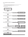
1. If an error occurs during operation, the LED flashes to indicate that there is a problem then all operations stop except LED.
2. When resuming operation with remote controller and switch, it determines error mode after normal operation.
QLED lamp display when error is detected
Error LED lamp Display
Cause
Operation
(Green)
X
X
X
X
X
X
X
X
Actions to take
Defrost
(Red)
X
X
X
X
X
X
X
X
X
X
t$IFDLUIFDPOOFDUJPOCFUXFFOUIFSPPN
temperature wire and the main PCB of the indoor
t#SFBLBXBZGSPNUIFSPPNUFNQFSBUVSF
unit
sensor connector
t$IFDLUIFQBUUFSOPGUIFSPPNUFNQFSBUVSF
t$VUUIFSPPNUFNQFSBUVSFTFOTPSXJSF
sensor part of the main PCB of the indoor unit
and if parts are open or shorted
X
t$IFDLUIFDPOOFDUJPOCFUXFFOUIFNBJO1#PG
t%JTKPJOUPGUIFJOPVUTFOTPSDPOOFDUPS
the indoor unit and heat exchange sensor wire.
of the indoor heat exchanger
t$IFDLUIFQBUUFSOPGUIFIFBUFYDIBOHFSPGUIF
t$VUUIF*OPVUTFOTPSXJSFPGUIF
main PCB of the indoor unit and if parts are open
indoor heat exchanger
or shorted
X
t*OEPPSGBONPUPSJTOPOPQFSBUJWF
t*OEPPSGBONPUPSJTPQFSBUJOHTMPXMZ
t*OEPPSGBONPUPSPQFSBUFTBUBO
excessive speed.
t$IFDLJGBNPUPSDPOOFDUPSIBTCFFO
dismounted (CN44. CN73)
t$IFDLUIFGBTUFOJOHPGUIFNPUPSGBO
X
t%JTKPJOUFEPSDVUPGGPGPVUEPPS
temperature sensor
t%JTKPJOUFEPSDVUPGGPGUIFPVUEPPS
sensor of heat exchanger (COND)
t%JTNPVOUFEDVUPGGPGUIFPVUEPPS
discharge sensor
t$IFDLUIF1$#EJTQMBZXJOEPXPGUIFPVUEPPS
unit then refer to a breakdown diagnosis
X
t$PNNVOJDBUJPOFSSPSCFUXFFOJOEPPS
units and outdoor units for more than
t$IFDLUIFDPOOFDUJPOCFUXFFOJOEPPSBOE
2 minutes
outdoor units
tNJOFSSPSPGUIFPVUEPPSVOJU
t$IFDLUIFTFUUJOHTGPSJOEPPS.BJO3.$
tracking (multi-product specification)
address switch
t*ODPOTJTUFODZCFUXFFOUIFOVNCFS
of installed units and communication
units. (multi-product specification)
t5IFEFUFDUJPOPGTFDPOEBSZIJHI
temperature at COND (outdoor heat
exchanger)
t5IFEFUFDUJPOPGTFDPOEBSZIJHI
temperature at discharge
t3FWFSTFEFUFDUJPOFSSPS
t$IFDLUIF1$#EJTQMBZXJOEPXPGUIFPVUEPPS
unit then refer to breakdown diagnosis
t%FWJBUJPOPGGMPBUTFOTPSDPOOFDUPS
t$VUPGGMPBUTFOTPSXJSF
t$IFDLUIFDPOOFDUJPOCFUXFFONBJO1$#BOE
float sensor in the indoor unit
: Turn on
4-14
: Flashing X : Turn off
Samsung Electronics
QLED lamp display when error is detected(cont.)
Error LED lamp Display
Cause
Operation
(Green)
Defrost
(Red)
X
X
X
X
X
Actions to take
t0QUJPOTFUVQFSSPSPOQFSJQIFSBMT
t$IFDLUIFTFUUJOHPG%*1TXJUDI4848
SW07)
t&&130.QBSUEFGFDU
t&&130.DJSDVJUEFGFDU
t$IFDLOPOEFMJWFSZDPPMEFMJWFSZOPOJOTFSUJPO
of IC51 Part Pin
t$IFDLOPOEFMJWFSZDPPMEFMJWFSZOPOJOTFSUJPO
of IC51 peripheral circuit components
t&&130.PQUJPOOPOFJOQVUFSSPOFPVT t3FJOQVUPGPQUJPODPEFGPSJOEPPSVOJUSFGFSUP
input
page 4-11)
: Turn on
Samsung Electronics
: Flashing X : Turn off
4-15
QLED lamp display when error is detected(cont.)
Error LED lamp Display
Product operation status in case of error
Diagnosis Method
Fan
Outdoor unit
Compressor
Operation-Off
Operation-Off
Operation-Off
Page 4-21
X
Operation-Off
Operation-Off
Operation-Off
Page 4-22
Indoor unit Fan
Operation
(Green)
Defrost
(Red)
X
X
X
X
X
X
X
Outdoor unit
X
X
X
Operation-Off
Operation-Off
Operation-Off
Page 4-23
X
X
X
Operation-Off
Operation-Off
Operation-Off
Page 4-32
X
Operation-Off
Operation-Off
Operation-Off
Page 4-24
Operation-Off
Operation-Off
Operation-Off
Page 4-34
Operation-Off
Operation-Off
Operation-Off
Page 4-25
Operation-Off
Operation-Off
Operation-Off
-
Operation-Off
Operation-Off
Operation-Off
Page 4-26
Operation-Off
Operation-Off
Operation-Off
Page 4-11
X
X
X
X
X
X
X
X
X
X
X
X
: Turn on
4-16
: Flashing X : Turn off
Samsung Electronics
4-2-5 Troubleshooting for outdoor unit
If an error occurs during the operation, it is displayed on the outdoor unit PCB LED, both MAIN PCB and INVERTER PCB.
No.
Error Code
1
E201
Unit quantity miss matching between indoor and outdoor.
2
E202
Abnormal state, no communication between Indoor and Outdoor
Main PCB
Check electrical connection and setting
3
E203
1min. Time out of communcation error(Main¥Inverter)
Check electrical connection and setting
4
E221
Outdoor temp sensor error
Check Outdoor sensor Open/Short
5
E231
Cond. temp sensor error
Check Cond. sensor Open/Short
6
E251
Discharge temp sensor error
Check Discharge sensor Open/Short
7
E320
OLP Sensor Error
Check OLP sensor Open/Short
8
E403
Detection of Outdoor Freezing when Comp. Stop
Check Outdoor Cond.
9
E404
Protection of Outdoor Overload when Comp. Stop
Check Comp. when it start
10
E416
E440
11
E441
12
E458
E475
Meaning
Remarks
Check indoor quantity setting in outdoor
(Refer to page 17.)
Discharge temperature of a compressor in an
outdoor unit is overheated.
Heating operation is not available since the outdoor air temperaHeating
ture is over 30°C.
Cooling operation is not available since the outdoor air temperaCooling
ture is lower than -5°C.
Outdoor unit BLDC Fan 1 or Fan 2 error
FAN1 error
FAN2 error
13
E461
Comp. Starting error
14
E462
Primary Current Trip error
15
E463
Over current trip / PFC over current error
16
E464
IPM(IGBT Module) Over Current(O.C)
17
E465
Comp. Over load error
18
E466
DC-Link voltage under/over error
Check AC Power or DC_Link voltage
19
E467
Comp. wire missing error
Check Comp. wire
20
E468
Current sensor error
Check Outdoor Inverter PBA
21
E471
Outdoor EEPROM error
Check Outdoor EEPROM date
22
E474
IPM(IGBT Module) or PFCM Temperature sensor Error
Check Outdoor Inverter PBA
23
E484
PFC Overload Error
Check Outdoor Inverter PBA
24
E500
IPM is over heated.
Check Outdoor Inverter PBA
25
E554
GAS Leak error
Check indoor and outdoor unit model
26
E556
Capacity miss match between indoor and outdoor
Check indoor and outdoor unit model
Samsung Electronics
Check OLP sensor
4-17
4-2-6 Wired remote controller
- If an error occurs, (
) icon will be displayed on the wired remote controller.
- Press the Test button to see the error code.
Product operation in
error condition
Error mode
4-18
Contents
Measure
Outdoor unit/
Compressor/Indoor
unit
Error type
Indoor unit communication error
Check the communication cable of indoor
unit. Check the DC output voltage at the
communication terminal
Operation Off
Communication
error
Indoor unit/outdoor unit
communication time-out error: errors
in more than 6 packets
Check the outdoor communication cable
connection. Check DC output voltage and the
communication terminal
Operation Off
Communication
error
Indoor temperature sensor (open/
short error)
Check indoor unit room temperature sensor.
Check indoor unit PCB connector CN41 (White)
Operation Off
Indoor sensor
error
Indoor unit Eva In sensor (Open/Short)
Check indoor unit pipe sensor. Check indoor PCB
connector CN41(White)
Operation Off
Indoor sensor
error
Indoor unit Eva In sensor
disconnection
Check the disconnection of indoor unit pipe
sensor
Operation Off
Indoor sensor
error
Remocon Option for MDS is set for ON,
but MDS kit is disconnected or the
signals for sensors are abnormal.
Check the wire connection
Check the MDS kit
Check the main PBA
Indoor floating switch secondary
detection
Check indoor unit float sensor. Check indoor PCB
connector CN5 (black)
Operation Off
Self diagnostic
error
Indoor/outdoor communication error
(1 min)
Check the communication connection between
indoor and outdoor units. Check the power line
and communication cable connection status
Operation Off
Communication
error
Communication error between
indoor/outdoor INVlMAIN MICOM (1
min)
Check MAIN MICOM
Check INVERTER MICOM
-
Communication
error
Outdoor temperature sensor error
Check sensor connection status
Check sensor location
Check sensor resistance
Operation Off
Outdoor sensor
error
COND temperature sensor error
Check sensor connection status
Check sensor location
Check sensor resistance
Operation Off
Outdoor sensor
error
[Inverter] Emission temperature sensor
error
Check sensor connection status
Check sensor location
Check sensor resistance
Operation Off
Outdoor sensor
error
Emission temperature excessively high
No error (DISCHARGE temperature control)
-
Outdoor unit
protection
control error
Heating operation blocked
Check the operation setting state
Check temperature sensor
Operation Off
Self diagnostic
error
Cooling operation blocked
Check the operation setting state
Check temperature sensor
Operation Off
Self diagnostic
error
Outdoor fan 1 error
Check input power connection status
Check the connection status between the motor
and outdoor unit PCB
Check indoor/outdoor fuse
Operation Off
Self diagnostic
error
[Inverter] Compressor startup error
Check the compressor connection status
Check the resistance between difference phases
of the compressor
Operation Off
Outdoor unit
protection
control error
[Inverter] Total current error/PFC over
current error
Check the input power
Check the coolant charging status
Check the normal operation of outdoor fan
Operation Off
Outdoor unit
protection
control error
Normal operation
(without MDS kit)
MDS kit Error
Samsung Electronics
Wired remote controller (cont.)
Product operation in
error condition
Error mode
Contents
Measure
[Inverter] IPM over current
error
Check coolant charging
Check the compressor connection status and normal
operation
Check the obstacles around the indoor and outdoor units
Check whether the outdoor unit service valve is open
Check whether the indoor/outdoor installation pipe/
wiring are correct
Operation Off
Outdoor unit
protection
control error
Check the compressor connection status
Check the resistance between difference phases of the
compressor
Operation Off
Outdoor unit
protection
control error
Restart in 3 minutes
Outdoor unit
protection
control error
Compressor V limit error
Outdoor unit/
Compressor/Indoor
unit
Error type
DC LINK over/low voltage error
Check input power
Check AC power connection
[Inverter] Compressor rotation
error
Check the compressor connection status
Check the resistance between difference phases of the
compressor
Operation Off
Outdoor unit
protection
control error
[Inverter] Current sensor error
Check EEPROM DATA
Check the normal operation of PCB
Operation Off
Outdoor unit
protection
control error
Check the input power connection
Check the status of RY21 and R200 in the INVERTER PCB
Operation Off
Outdoor unit
protection
control error
Check EEPROM DATA
Check the normal operation of PCB
Operation Off
Outdoor unit
protection
control error
Check the input power status
Operation Off
Outdoor unit
protection
control error
Check the compressor connection status
Check the resistance between difference phases of the
compressor
Operation Off
Outdoor unit
protection
control error
Check the input power connection status
Check the connection status of the motor and the
outdoor unit PCB
Check the indoor/outdoor unit fuse
Operation Off
Self diagnostic
error
Check the coolant charging status
Check the indoor EVA sensor
Check if the outdoor unit service value is open
Check that the indoor/outdoor installation pipe/wiring
are correct
Operation Off
Self diagnostic
error
Check the option code of the indoor unit
Operation Off
Outdoor unit
protection
control error
[Inverter] DC LINK voltage
sensor error
[Inverter] OTP error
AC ZERO CROSSING SIGNAL
OUT error
Compressor LOCK error
Outdoor fan 2 error
Gas leak error
Capacities not matched
Communication error between
the indoor unit and wired
remote controller
Check the connection wire between the indoor unit and
the wired remote controller
Normal operation
Wired remote
controller error
Communication error between
the Master and Slave wired
remote controllers
Check the option switch for defining the Master and
Slave (only one Master and one Slave can exist)
Normal operation
Wired remote
controller error
COM1/COM2 cross installation
error
Check that wired remote controller is connected to the
COM2 terminal of the indoor unit
Normal operation
Wired remote
controller error
Wired remote controller COM2
option setting error
Check that Com1, Com2 setting DIP switch is set to Com2
Normal operation
Wired remote
controller error
Samsung Electronics
4-19
4-3 Troubleshooting by symptoms
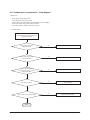
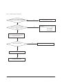
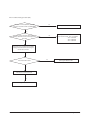
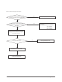
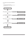
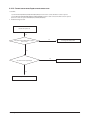
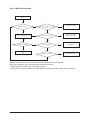
4-3-1 Indoor temperature sensor (open/short)
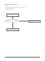
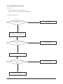
Indoor unit display
X (Operation)
(Defrost) X (Timer) X (Filter)
In case of open or short circuit of indoor temperature sensor
Symptom
Short or leakage of the corresponding sensor
Failure
Is indoor temperature
sensor disconnected from the
connector in PCB?
No
Yes
Restart the system after connecting
to the PCB connector
Remove the indoor temperature sensor
connector from the PCB and measure the
resistance between two terminals
<Temperature sensor
resistance value>
Current
Resistance
temperature
(kΩ)
(°C)
In this case, is the resistance
value out of range in the temperature
table on the right?
No
Restart the system after replacing the PCB
4-20
Yes
Indoor temperature sensor
failure (replace)
40
5.800
35
6.900
30
8.300
25
10.00
20
12.10
15
14.70
10
18.00
5
22.00
0
28.30
-5
33.90
-10
42.30
Samsung Electronics
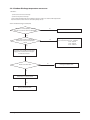
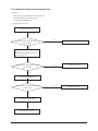
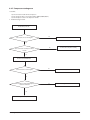
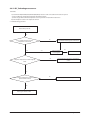
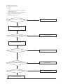
4-3-2 Indoor heat exchanger temperature sensor (open/short)
Indoor unit display
(Operation)
(Defrost) X (Timer) X (Filter)
Short or open circuit of indoor heat exchanger temperature sensor
Symptom
Short or open circuit in the corresponding sensor
Failure
Is the indoor heat exchanger
temperature sensor connector disconnected
from the PCB?
No
Yes
Restart the system after
connecting the connector to PCB
Remove the indoor heat exchanger
temperature sensor connector from
the PCB and measure the resistance
between two terminals
<Temperature sensor
resistance value>
Current
Resistance
temperature
(kΩ)
(°C)
In this case, is the resistance
value out of range in the temperature table
on the right?
No
Restart the system after replacing the PCB
Samsung Electronics
Yes
Failure of the indoor heat
exchanger temperature sensor
(replace)
40
5.800
35
6.900
30
8.300
25
10.00
20
12.10
15
14.70
10
18.00
5
22.00
0
28.30
-5
33.90
-10
42.30
4-21
4-3-3 Indoor FAN error
Indoor unit display
Symptom
Failure
X (Operation)
X (Defrost)
(Timer) X (Filter)
Indoor unit fan does not run /Runs at excessive high speed and stops
Check if the motor connector is disconnected/ check the motor fan assembly status
Is the motor connector
disconnected from the PCB?
Yes
Connect the connector to
PCB and restart the unit
No
Is there foreign substance
stuck in the motor fan?
Yes
Yes
Remove the foreign substance
and restart the unit
Replace the PCB and restart the unit
4-22
Samsung Electronics
4-3-4 Communication error after finishing Tracking
Indoor unit display
X (Operation)
(Defrost)
(Timer) X (Filter)
Communication error between the indoor and outdoor unit for two minutes
Symptom
Communication error between the indoor unit and outdoor unit
Failure
No
Is there a response from the indoor PCB?
(LED01 (RED) is not ON)
Check the communication cable and
replace the indoor unit PCB
LED01
Yes
Remove the communication cable
connecting the outdoor unit to indoor unit,
and measure the signal on LINE 2 of the
outdoor unit with a scope
In this case, is the
voltage waveform between the lines square
wave with amplitude over ±0.7V as shown
in the following picture?
No
Check the communication
cable in the outdoor unit PCB
and replace the PCB
Yes
Reconnect the cable connecting
the outdoor unit to the indoor unit
and restart the unit.
If the communication still doesn’t work,
replace the indoor unit PCB.
Good
Bad
+0.7V
-0.7V
Samsung Electronics
4-23
4-3-5 Indoor unit float sensor error
Indoor unit display
X (Operation)
X (Defrost)
(Timer)
(Filter)
The indoor unit floating sensor is open and that state is maintained for more than one minute
Symptom
Increase in the drain pan water level due to failure of the indoor unit drain pump,
or float sensor failure
Failure
Error occurs
Remove the floating sensor
connector connected to the indoor unit
PCB and the resistance measured between the
two terminals. Is the resistance ∞?
(open circuit)
No
Reassemble the floating sensor
connector and reset the outdoor unit
power. (Indoor unit power reset is
required)
Yes
Same error occurs again
No
Is the water level in the drain pan high?
Yes
Yes
No
Replace the indoor unit PCB
Reset the indoor unit power and
check the operation of the drain pump.
(it vibrates when operating)
Normal operation
Does drain pump operate
when compressor operates?
No
Drain pump PCB
Is the terminal voltage around
DC12V?
Yes
Is the water level in
drain pan decreasing?
Yes
Replace the floating sensor
when it fails and reset the
indoor unit power
No
Yes
No
Replace the drain pump
Replace the indoor unit PCB
Normal operation
Replace the drain pump
4-24
t 'MPBUTFOTPSFSSPSJTDMFBSFEPOMZ
when the indoor power is reset
Samsung Electronics
4-3-6 EEPROM circuit failure
Indoor unit display
Symptom
Failure
(Operation)
(Defrost)
(Timer) X (Filter)
EEPROM circuit failure
EEPROM component failure, EEPROM circuit parts missing/damaged/soldering failure
Are the EEPROM PBA or Components
in good conditions?
(Disconnected from Main PBA/soldering failure
/ missing components / damage)
No
Yes
Restart the unit
after replacing or reconnecting the
EEPROM PBA.
If the operation failed again
Replace the Main PBA
Samsung Electronics
4-25
4-25
4-3-7 Outdoor unit is not powered on – Initial diagnosis
1. Check items
1) Is the power supply voltage 220V?
2) Is the AC power connected correctly?
3) Are the LEDs in the main PCB and inverter PCB of the outdoor unit ON?
4) Is the input power voltage of the indoor unit 220V?
5) Is the wired remote controller connected correctly?
2. Check procedure
Turn off the main power switch
(circuit break of power outlet) and turn on
again after 30 seconds.
Is the outdoor unit power
supply (L-N) 220V?
No
Check the input power
Yes
Is the outdoor unit power
voltage (L-N) 220V?
No
Check the connection of the terminal block
Yes
Is the voltage between
the terminal 2 (~) and 4 (~) of the
bridge diode 220V?
No
Replace the inverter PBA
Yes
Is the fuse connected?
No
Replace the fuse
Yes
Is the resistance value of R001 200Ω?
No
Replace the inverter PBA
Yes
Cont.
4-26
Samsung Electronics
Outdoor unit is not powered on – Initial diagnosis
(cont.)
Cont.
Yes
Is the reactor connector
connected correctly?
No
Connect the reactor
Yes
Replace the PBA.
Samsung Electronics
4-27
4-4-1 Communication error
1. 1.Checklist :
1) Is the cable between the indoor unit and outdoor unit connected correctly?
2) Isn't the power cable and communication cable cross?
2. Troubleshooting procedure
Restart after power off.
Is the communication error occurred again?
No
Terminate the service
Yes
Is the connection of power cable and
communication cable normal?
No
Correct the wrong cable
Yes
Is the power is normal?
(check the LED Lamp
No
Exchange the PBA of no power unit
Yes
Exchange the indoor unit PBA.
Yes
Is the communication error occurred again?
No
Terminate the service.
Yes
Exchange the outdoor unit PBA.
4-28
Samsung Electronics
4-4-2 Outdoor temperature sensor error
1. 1.Checklist :
1) Is the cable between the indoor unit and outdoor unit connected correctly?
2) Is the sensor placed correctly?
3) Does the both terminal of sensor satisfy the resistance value in accordance with temperature?
4) Is the resistance value of sensor connection pull-up correct?
4-4-2-1. Troubleshooting procedure (PF2)
Is the sensor connector(CN251) connected
correctly in accordance with a color(BLU,6PIN)?
No
Reconnect the sensor connector.
Yes
Is the sensor resistance value #1-#2
10kohm±3% at the room temperature
of 25°C
No
Yes
Sensor Replace
Sensor resistance value : 20°C - 12.09kohm
30°C - 8.31kohm
35°C - 6.94kohm
40°C - 5.83kohm
Connect the sensor to PBA connector (6pin)
supply power and measure the voltage of
#1-#2 in the connector
Below 0.5V or Over 4.5V?
Yes
Exchange the PBA of no power unit
No
Micom error or connector check
Yes
Exchange the Outdoor PBA
Samsung Electronics
4-29
4-4-2-2. Troubleshooting procedure (PF3)
Is the sensor connector(CN502) connected
correctly in accordance with a colorRED,4PIN)?
No
Reconnect the sensor connector.
Yes
Is the sensor resistance value #1-#2
10kohm±3% at the room temperature
of 25°C
No
Yes
Sensor Replace
Sensor resistance value : 20°C - 12.09kohm
30°C - 8.31kohm
35°C - 6.94kohm
40°C - 5.83kohm
Connect the sensor to PBA connector (4pin)
supply power and measure the voltage of
#1-#2 in the connector
Below 0.5V or Over 4.5V?
Yes
Exchange the PBA of no Ourdoor PBA
No
Micom error or connector check
Yes
Exchange the Outdoor PBA
4-30
Samsung Electronics
4-4-3 Outdoor Coil temperature sensor error
1.Checklist :
1) Is the sensor connected correctly?
2) Is the sensor placed correctly?
3) Does the both terminal of sensor satisfy the resistance value in accordance with temperature?
4) Is the resistance value of sensor connection pull-up correct?
4-4-3-1. Troubleshooting procedure (PF2)
Is the sensor connector(CN251) connected
correctly in accordance with a color(BLU,6PIN)?
No
Reconnect the sensor connector.
Yes
Is the sensor resistance value #5-#6
10kohm±3% at the room temperature
of 25°C
No
Yes
Sensor Replace
Sensor resistance value : 20°C - 12.09kohm
30°C - 8.31kohm
35°C - 6.94kohm
40°C - 5.83kohm
Connect the sensor to PBA connector (6pin)
supply power and measure the voltage of
#5-#6 in the connector
Below 0.5V or Over 4.5V?
Yes
Exchange the Outdoor PBA
No
Micom error or connector check
Yes
Exchange the Outdoor PBA
Samsung Electronics
4-31
4-4-3-2. Troubleshooting procedure (PF3)
Is the sensor connector(CN501) connected
correctly in accordance with a colorRED,4PIN)?
No
Reconnect the sensor connector.
Yes
Is the sensor resistance value #3-#4
(CN501) 10kohm±3% at the room temperature
of 25 25°C
No
Yes
Sensor Replace
Sensor resistance value : 20°C - 12.09kohm
30°C - 8.31kohm
35°C - 6.94kohm
40°C - 5.83kohm
Connect the sensor to PBA connector(4pin)
supply power and measure the voltage of
#3-#4 in the connector
Below 0.5V or Over 4.5V?
Yes
Exchange the Outdoor PBA
No
Micom error or connector check
Yes
Exchange the Outdoor PBA
4-32
Samsung Electronics
4-4-4 Outdoor Discharge temperature sensor error
1.Checklist :
1) Is the sensor connected correctly?
2) Is the sensor placed correctly?
3) Does the both terminal of sensor satisfy the resistance value in accordance with temperature?
4) Is the resistance value of sensor connection pull-up correct?
4-4-4-1. Troubleshooting procedure (PF2)
Is the sensor connector(CN251) connected
correctly in accordance with a color(BLU,6PIN)?
No
Reconnect the sensor connector.
Yes
Is the sensor resistance value #3-#4
10kohm±3% at the room temperature
of 25°C
No
Yes
Sensor Replace
Sensor resistance value : 20°C - 242kohm
30°C - 166ohm
35°C - 138ohm
40°C - 115kohm
Connect the sensor to PBA connector (6pin)
supply power and measure the voltage of
#3-#4 in the connector
Below 0.5V or Over 4.5V?
Yes
Exchange the Outdoor PBA
No
Micom error or connector check
Yes
Exchange the Outdoor PBA
Samsung Electronics
4-33
4-4-4-2. Troubleshooting procedure (PF3)
Is the sensor connector(CN502) connected
correctly in accordance with a colorRED,4PIN)?
No
Reconnect the sensor connector.
Yes
Is the sensor resistance value #3-#4
(CN501) 10kohm±3% at the room temperature
of 25 25°C
No
Yes
Sensor Replace
Sensor resistance value : 20°C - 242kohm
30°C - 166ohm
35°C - 138ohm
40°C - 115kohm
Connect the sensor to PBA connector(4pin)
supply power and measure the voltage of
#3-#4 in the connector
Below 0.5V or Over 4.5V?
Yes
Exchange the Outdoor PBA
No
Micom error or connector check
Yes
Exchange the Outdoor PBA
4-34
Samsung Electronics
4-4-5 Outdoor Discharge over temperature error
1.Checklist :
1) Check the discharge temperature in the outdoor unit
2) Check the compressor locking or gas leak
3) 3) Download the EEPROM data
2. Troubleshooting procedure
Restart after power off.
after 30min ~ 1Hr
Is the discharge over temperature sensor error
appeared again?
No
Terminate the service
Yes
The condition is too poor for air conditioner to
operate
Wait until discharge temperature is decreased
Restart after power off
Is the discharge over temperature sensor error
appeared again?
No
Terminate the service
Yes
Download the EEPROM data
Is the discharge over temperature sensor error
appeared again?
No
Terminate the service
Yes
Exchange the Outdoor PBA
Exchanged the Compressor
Samsung Electronics
4-35
4-4-6 Outdoor Fan motor error
1.Checklist :
1) Are the input power voltage and the power connection correct?
2) Is the motor wire connected to the outdoor PBA correctly?
3) Is there no assembly error or none-assembly in the terminal of motor wire connector?
4) Is there no obstacle at the surrounding of motor and propeller?
2. Troubleshooting procedure
Restart after power off.
Does the fan rotate?
No
Power off and Separate the Fan motor wire
from CN901 on Outdoor PBA
Yes
Reassemble the fan wire and input the power
again
Yes
Exchange the Fan motor
Is there short among each pin #1~#6
No
Is the fan error appeared again?
Terminate the service
No
Yes
Is the voltage of CN901 #1-#3 over 250Vdc
Is the voltage of CN901 #3-#5 and #3-#6 with in
1Vdc~15Vdc during the operation?
No
No
Follow the check procedure of outdoor unit
power supply error check
Exchange the Outdoor PBA
Yes
PBA problem or Motor problem
Change the PBA first and check the operation
Exchange the Fan motor
4-36
Samsung Electronics
4-4-7 Compressor starting error
1.Checklist :
1) Is the connection of cable for the compressor?
2) Is the compressor wire is connected clockwise? U(RED)-V(BLU)-W(YEL)
3) Is the interphase resistance of compressor normal?
2. Troubleshooting procedure
Restart after power off.
Is the restart error occurred again?
No
Terminate the service
Yes
Is the connection of compressor wire is
normal?
No
Connect the comp wire normally
Yes
Download the EEPROM data
Is the restart error occurred again?
No
Terminate the service
Yes
Is the compressor body and interphase
resistance insulated?
Yes
Exchange the Outdoor PBA
No
Exchanged the Compressor
Samsung Electronics
4-37
4-4-8 Compressor wire missing error/rotation error
1.Checklist :
1) Is the connection of cable for the compressor?
2) Is the compressor wire is connected clockwise? U(RED)-V(BLU)-W(YEL)
3) Is the interphase resistance of compressor normal?
2. Troubleshooting procedure
Restart after power off.
Is the restart error occurred again?
No
Terminate the service
Yes
Is the connection of compressor wire is
normal? (PBA and Compressor)
No
Connect the comp wire normally
Yes
Is the restart error occurred again?
No
Terminate the service
Yes
Is the compressor body and interphase
resistance insulated?
Yes
Exchange the Outdoor PBA
No
Exchanged the Compressor
4-38
Samsung Electronics
4-4-9 O.C(Over Current) error
1.Checklist :
1) Is the IPM Shunt(PF2:R451,R452,R453,PF3:R413,R414,R415) resistance value correct? Check the resistor is opened
2) Is the condition of surrounding temperature abnormal overload?
3) Is there any problem as like the temperature sensor separation or measurement value error?
4) Is the interphase resistance of compressor normal?
2. Troubleshooting procedure
Restart after power off.
No
Is the O.C error occurred?
Terminate the service
Yes
Is the connection of compressor wire is
normal?
No
Connect the comp wire normally
No
Terminate the service
Yes
Is the restart error occurred again?
Yes
Is the condition of indoor/outdoor
temperature normal load?
Yes
Is the position of temperature sensor and
sensing value normal?
No
Restart after returning to the normal load
Is the O.C error
occurred again?
Yes
No
No
Terminate the service
Correct the sensor position or exchange the
sensor
Yes
Is the compressor body and interphase
resistance insulated?
Yes
Exchange the Outdoor PBA
No
Exchanged the Compressor
Samsung Electronics
4-39
4-4-10 DC_link voltage sensor error
1.Checklist :
1) Is the input voltage of outdoor terminal block is normal?
2) Is the reactor wire connected?
3) Is the DC_link capacitor(PF2:CE101,CE102,CE103,PF3:CE001,CE002,CE003,CE004)) assembled in accordance the specification?
(Outdoor PBA)
4) Is the DC_link resistor(PF2:R104,R106,R107,R108,PF3:R004,R005,R006,R007) value is normal? (Outdoor PBA)
2. Troubleshooting procedure
Is the connected of reactor wire?
(PBA-Reactor)
No
Connect the reactor wire
Yes
Restart after power off.
Start the operation (cooling mode or heating
mode)
Is the DC_link voltage (CE101 or CE001) is
normal in operation mode?
Normal range(280Vdc~320Vdc)
No
Check the power input
Yes
Is the DC_link sensing voltage(R104 or R004) is normal in
operation mode?
Normal range (0.2Vdc~2.8Vdc)
No
Exchange the Outdoor PBA
Yes
Is the reactor insulation damaged?
No
Exchange the Outdoor PBA
No
Exchange the Reactor
4-40
Samsung Electronics
4-4-11 DC_link voltage under/over error, Over voltage protection error/PFC over load
1.Checklist :
1) Is the input voltage of outdoor terminal block is normal?
2) Is the reactor wire connected?
3) Is the reactor wire connected?
4) Is the DC_link capacitor(PF2:CE101,CE102,CE103,PF3:CE001,CE002,CE003,CE004)) assembled in accordance the specification?
(Outdoor PBA)
5) Is the DC_link resistor(PF2:R104,R106,R107,R108,PF3:R004,R005,R006,R007) value is normal? (Outdoor PBA)
2. Troubleshooting procedure
Is the connected of reactor wire?
(PBA-Reactor)
No
Connect the reactor wire
Yes
Restart after power off.
Is the the input voltage is nomal?
Normal range(180Vac ~ 270Vac)
No
Check the input power in the powercord.
Yes
Restart after power off.
Start the operation (cooling mode or heating
mode)
Yes
Is the DC_link voltage (CE101 or CE001) is normal in operation
mode?
Normal range(280Vdc~320Vdc)
No
Check the input power
Yes
Is the DC_link sensing voltage(R104 or R004) is
normal in operation mode?
Normal range (0.2Vdc~2.8Vdc)
No
Exchange the Outdoor PBA
Yes
No
Is the reactor insulation damaged?
Exchange the Outdoor PBA
Yes
Exchange the Reactor
Samsung Electronics
4-41
4-4-12 DC_link voltage sensor error
1.Checklist :
1) Is the PFC Shunt(PF2:R062,R063,PF3:R807,R808,R809) resistance value correct? Check the resistor is opened
2) Is the condition of surrounding temperature abnormal overload?
3) Is there any problem as like the temperature sensor separation or measurement value error?
4) Is the interphase resistance of compressor normal?
2. Troubleshooting procedure
Restart after power off.
Yes
No
Is the condition of indoor/outdoor
temperature normal load?
Yes
Restart after returning to the normal load
No
Yes
Is the I_trip error
occurred again?
No
Is the position of temperature sensor and the sensing value
normal?
Terminate the service
Correct the sensor position or exchange the
sensor
Yes
Is the connection cable for the compressor and
power terminal normal?
No
Correct the cable connection
No
Exchange the Outdoor PBA
4-42
Samsung Electronics
4-4-13 Current sensor error/Input current sensor error
1.Checklist :
1) Is the PFC Shunt(PF2:R062,R063,PF3:R807,R808,R809) resistance value correct? Check the resistor is opened
2) Is the IPM Shunt(PF2:R451,R452,R453,PF23:R413,R414,R415) resistance value correct? Check the resistor is opened
3) Is there no short or open around IC451(PF2) or IC451,IC452(PF3)?
2. Troubleshooting procedure
Restart after power off.
Yes
Is the PFC shunt and IPM shunt resistance
value correct?
No
Exchange the Outdoor PBA
Yes
No
Terminate the service
Is the current sensor error appeared again?
Yes
Exchange the Outdoor PBA
Samsung Electronics
4-43
4-4-14 Heatsink sensor error/Heatsink over heat
1.Checklist :
1) Are there screws assembly in PBA-heatsink?
2) Is the gap PBA-heatsink
3) Is the fan operation normal?
4) Is the cover assembly in conrol-box normal?
2. Troubleshooting procedure
Restart after power off.
Yes
Are there screws in PBA-heatsink?
(4 screws)
No
Fastening the screw
Yes
Is the fan operation normal?
No
Check the fan connection
Change the Fan motor
Yes
Exchange the Outdoor PBA
4-44
Samsung Electronics
4-4-15 Comp Vlimit error/Comp current limit error
1.Checklist :
1) Is the PFC Shunt(PF2:R062,R063,PF3:R807,R808,R809) resistance value correct? Check the resistor is opened
2) Is the condition of surrounding temperature abnormal overload?
3) Is there any problem as like the temperature sensor separation or measurement value error?
4) Is the interphase resistance of compressor normal?
2. Troubleshooting procedure
Restart after power off.
Yes
No
IIs the O.C error occurred?
Terminate the service
Yes
No
Is the connection of compressor wire is
normal?
Connect the comp wire normally
Yes
No
Terminate the service
Is the O.C error occurred again?
Yes
No
Is the condition of indoor/outdoor
temperature normal load?
Yes
Is the position of temperature sensor and
sensing value normal?
Yes
Restart after returning to the normal load
No
Is the O.C error occurred
again?
No
Terminate the service
Correct the sensor position or exchange the
sensor
Yes
Is the compressor body and interphase
resistance insulated?
No
Exchange the Outdoor PBA
No
Exchange the Outdoor PBA
Samsung Electronics
4-45
4-4-16 EEPROM error/OTP error
1.Checklist :
1) Is there a short around micom?
2) Is there a short around IC202(PF2) or IC701(PF3)?
3) Did you download or insert EEPROM IC, after changing outdoor PBA?
2. Troubleshooting procedure
power off and download EEPROM data
(or. Insert the service EEPROM IC)
Restart after power off
Is the error appeared again?
No
Terminate the service
Yes
Exchange the Outdoor PBA
4-46
Samsung Electronics
4-4-17 AC zero cross signal error
1.Checklist :
1) Check the power condition at customer's house (Is there any power noise?)
2) Have been there power failure?
2. Troubleshooting procedure
Restart after power off
Is the AC line zero cross signal error appeared
again?
No
Terminate the service
Yes
Exchange the Outdoor PBA
Samsung Electronics
4-47
4-4-18 Operation condition secession error
1.Checklist :
1) Check the temperature around the outdoor unit.
2. Troubleshooting procedure
Restart after power off
Is the operation condition secession error
appeared again?
No
Terminate the service
Yes
* Heating mode *
Is the outdoor temperature over 40°C or under
-30°C?
* Cooling mode *
Is the outdoor temperature under °C?
Yes
The temperature condition is too poor to operate.
Wait until temperature is changed
4-48
Samsung Electronics
4-4-19 Capacity miss match error
1.Checklist :
1) Check the Btu between indoor and outdoor unit
2) Check the indoor unit option and outdoor unit EEPROM data
2. Troubleshooting procedure
Is the rated Btu between indoor unit and
outdoor unit?
No
Exchange the one of them according to the
exact model spec
Yes
Reset the option code again at indoor unit
Is the capacity miss match error appeared
again?
No
Terminate the service
Yes
Download the EEPROM data
Is the capacity miss match error appeared
again?
No
Terminate the service
Yes
Exchange the Outdoor PBA
Exchange the Indoor PBA
Samsung Electronics
4-49
4-4-20 Gas leak error
1.Checklist :
1) Is the position of indoor Eva_in sensor normal?
2) Check the pipe crack
3) Check the EEV valve connection in Outdoor unit
4) Check the refrigerant was charged
2. Troubleshooting procedure
Is the position of indoor eva_in sensor normal?
No
Indoor sensor take the normal position
Yes
Restart after power off
Yes
Is the gas leak error appeared again?
No
Terminate the service.
Yes
Check the EEV valve operation.
Yes
Is the EEV valve connection normal?
No
Connect the EEV valve.
Yes
Is the EEV valve is operation?
Check the sound of EEV valve after power on.
No
Change the EEV valve
Yes
Is the pressure of refrigerant normal?
No
Check the pipe crack.
Fill up the refrigerant.
Yes
Exchange the Indoor PBA
Exchange the Outdoor PBA
4-50
Samsung Electronics
4-4-21 MDS Error Flow chart
Start
Yes
MDS Function On
Yes
$IFDLJTTFHTFUUPiwJOPQUJPO
code
No
Yes
Does any error message pop up ?
No
MDS has no problem
Set seg23 to 1~8 digit
Check the wire connection
-Replace wire of MDS
-Connect wire of MDS
No
Yes
Check the MDS kit
Replace MDS Kit
No
End
Check the main PBA
Yes
Replace Main PBA
No
KMDS Function only can be set in wired remote controller or central controller.
KError Message(Error message will be appeared after 3minutes)
8JSFESFNPUFDPOUSPMMFSi&wNFTTBHFJTQPQVQ
-Display Panel: Operation & filter LED is blinking at the same time,after indoor unit is power off.
Samsung Electronics
4-51
5. PCB Diagram
5-1 PCB Diagram
5-1-1 MINI 4 WAY Indoor Unit
6
1
2
4
8
5
7
3
9
10
11
13
12
13
14
16
15
① Main power input
1(L):Phase L
2(N):Phase N
② BLDC fan
#1:DC310V
#2:Not used
#3:AGND
#4:DC15V
#5:FAN RPM
#6:RPM FEEDBACK
③
⑤ Eva in/out sensor
#1:EVA IN temperature sensor
#2,4,6:GND
#3:EVA Out temperature sensor
#5:EVA discharge
⑥ Room temperature
#1:Room temperature sensor
#2:GND
⑦ S/W download
S/W download
⑧ Panel display
#1:DC12V
#2-5: LED control signal
#6: REMOCON signal out
#7,8: Not used
#9: REMOCON_INT
#10:GND
#11:Vcc
⑨ VENT
#1:DC12V
#2:VENT_OUT
⑩ Panel flaps
#1:DC12V
#2-5: Louver control signal
#6: DC12V
#7-10: :Louver control signal
⑪ SPI
#1,2:GND
#3:SPI CONTROL
#4:Not Used
⑫ Drain Pump
#1:DC12V
#2:DRAIN_PUMP_OUT
⑬ Human Sensor
#1:DC12V
#2:Com4_TXD
#3:Com4_RXD
#4:Human sensor reset
#5:GND
⑭ External
#1,3:DC12V
#2:Error_CHK_OUT
#4:Comp_CHK_OUT
⑮ External
#1:EXT_CTRL
#2:GND
⑯ COM1,COM2,V1,V2
F3-F4:Com2
V1-V2:DV12V
F1-F2:Com1
5-1
Earth wire
#1:GND
④ Float switch
#1:Float_SW
#2:GND
Samsung Electronics
5-1-2 Panel PCB
1
① CN01-DISPLAY
#1 : DC 12V
#2~5 : LED control signal
#6 : Remocon signal out
#7~8 : Not used
#9 : Remocon signal IN
#10: GND
#11: DC 5V
Samsung Electronics
5-2
5-1-3 SLIM 1 WAY Indoor Unit
13
14
4
15
12
11
10
6
18
9
8
7
5
2
16
1. CN75-Ventilator Output
#1 : POWER(N)
#3 : POWER(L)
2. CN74-Ventilator Output
#1 : POWER(N)
#3 : POWER(L)
6. CN32-DC12V Ouput
#1 : DC12V
#2 : GND
7. CN10-MICOM DOWNLOAD
11. CN31 - COM1 COMM.
#1 : F1
#2 : F2
12. CN33 - COM2 COMM.
#1 : F3
#2 : F4
16. CN83- EXT CTRL
#1 : ON/OFF External Control 17. Delete
#2 : GND
5-3
3. CN73-Fan Motor
#1 : Capacitor Output
#3 : SSR Output
#5 : POWER(N)
8. CN91-DISPLAY
#1,2,3,4,5 : LED Control
#6 : Not used
#7 : Remocon signal Input
#8 : GND
#9 : DC5V
13. CN41 - THERMISTOR
#1 : ROOM THERMISTOR
#2 : GND
#3 : EVA-IN THERMISTOR
#4 : GND
18. CN45-SPI
#1,2 : SPI Signal Output
#3 : DC12V
1
4. CN71-AC POWER
#1 : POWER(L)
#3 : POWER(N)
5. CN44 - RPM Feedback
#1 : DC5V
#2 : GND
#3 : RPM Feedback
9. CN60-STEP MOTOR
#1 : DC12V
#2,3,4,5 : LOUVER Control
Signal output
10. CN81-External Output
#1 : DC12V
#2 : ERROR Signal output
#3 : DC12V
#4 : COMP Signal output
14. CN42 - EVA OUT
15. CN51 - FLOAT SENSOR
THERMISTOR
#1 : FLOAT S/W SENSOR
#1 : EVA OUT THERMISTOR
#2 : GND
#2 : GND
Samsung Electronics
3
5-1-4 Outdoor Unit PCB
Outdoor Unit PCB (cont.)
Q Main PCB
1
2
3
4
5
6
7
8
9
10
11
① OLP /COND THERMISTOR CONNECTOR
② OUT/DISCHARGE THERMISTOR CONNECTOR
③ BLDC-FAN CONNETCOR
④ EEV-A CONNECTOR
⑤ DISPLAY CONNECTOR
⑥ DISPLAY CONNECTOR
⑦ PC DOWNLOADCONNECTOR
⑧ S NE T CONNECTOR
⑨ AS-PRO DOWNLOAD CONNECTOR
⑩ DISPLAY CONNE CTORS
⑪ DOWNLOAD-INV CONNECTOR S
Samsung Electronics
SMAW250A-04 WHT
SMAW250A-04 RE
YAN396-06V WHT
SMAW250A-05 RED
SMW200-10 NTR
SMAW250A-03 RED
SMW200-10 BLK
SMW200-04 NTR
SMAW200A-07 WHT
MW200-05 NTR
MW200-10 RED
5-4
Outdoor Unit PCB (cont.)
Q Sub PCB
1
① 12V POWER CONNECTOR
② MAIN -SUB SIGNAL CONNECTOT
③ MAIN -SUB SIGNAL CONNECTOT
Samsung Electronics
2
3
YW396-02V BLU
SMW250-04 WHT
SMW200-15NTR
5-5
6. Wiring Diagram
6-1 Indoor Unit
6-1-1 MINI 4 WAY Indoor Unit
This Document can not be used without Samsung’s authorization.
6-1
Samsung Electronics
6-1-2 SLIM 1 WAY Indoor Unit
This Document can not be used without Samsung’s authorization.
Samsung Electronics
6-2
6-2 Outdoor Unit
QOutdoor Unit : RC026DHXEA/ RC035DHXEA/ RC052DHXEA
This Document can not be used without Samsung’s authorization.
6-3
Samsung Electronics
QOutdoor Unit : RC060DHXEA/ RC071DHXEA
This Document can not be used without Samsung’s authorization.
Samsung Electronics
6-4
7. Schematic Diagram
7-1 Indoor Unit
7-1-1 MINI 4 WAY MAIN PCB
41*@$53&&7@"
&&7@#
&&7@"@CBS
&&7@#@CBS
;$1@14
5-1(#
$
O'
7
(/%
065
065
*/
*/
*/
*/
(/%
3
"(/%
1"*/01@1
744
1"*/01@/&9*
O3&4&5
1"*/01@0&9*
, + 8
$
V'
7
108&3@4&/403
$
V'
7
$
O'
7
9065
101@164"3559%
9*/
101@/64"3539%
101@064"35$-,"%53(
101@1$"/59%441'44
95065
101@/$"/39%441$-,
.0%&
101@0**$4$-441.*40
.$
4'.(
101@1**$4%"441.04*
GPS@NBJO@*7$@7%%$03&
101@/64"3559%
*7$065
101@064"3539%
#-%$'"/
64"3559%7-$%1
118.0''
&9*518.$0.1
118.6
&9*5$"1$0.1
118.%
518.$0.1
118.6
5$"1$0.1
118.%
"%53(518.4&(1
118.6
.#3$5
7 "
9
4
$
4
'
4
/$
4
% 5017(4
18.64"3559%4&(1
&9*64"35$-,4&(1
441'44$"/59%4&(1
18.64"3539%4&(1
441$-,$"/39%4&(1
441.04***$4$-4&(1
441'444&(1
441.*40**$4%"4&(1
441.*404&(1
441.04*4&(1
441$-,4&(1
1)"4&;4&(1
1)"4&(1
64"3559%4&(1
64"3539%4&(1
&9*64"35$-,4&(1
744
7%%*0
18.4&(1
64"3559%518.4&(1
18.4&(1
18.4&(1
64"3539%5$"14&(1
64"35$-,5$-,4&(1
$"/39%518.4&(1
$"/59%5$"14&(1
&9*5$-,4&(1
&9*5$-,4&(1
**$4$-5$"14&(1
**$4%"518.4&(1
&9*5$-,4&(1
1)"4&"4&(1
7
$
V'
7
3&.0$0/@*/5
&&7@#@CBS
&&7@"@CBS
&&7@#
&&7@"
*
0
*
0
*
0
*
0
*
0
*
0
*
0
(/%
7$$
-&%@@065
-&%@@065
-&%@@065
-&%@@065
-73@"@065
-73@#@065
-73@"@CBS@065
3&4&5
&3
$
V'
7
015*0/
1$
(/%
7&/5*-"503
7
300.5&.1
0
*
0
*
0
*
0
*
0
*
0
*
0
(/%
7$$
-73@#@CBS@065
-73@"@065
-73@#@065
-73@"@CBS@065
-73@#@CBS@065
-73@"@065
$0.$0.-&%
7
-&%@$0.@065
-&%@$0.@065
(/%
*
0
*
0
*
0
*
0
*
0
*
0
*
0
(/%
(/%
7$$
-73@#@065
-73@"@CBS@065
-73@#@CBS@065
-73@"@065
-73@#@065
-73@"@CBS@065
-73@#@CBS@065
&7"*/
$
V'
7
$
$
7O'
$
V'
7
7O'
3
3
$
O'
7
O 7 ,'8
+ 8
5-1(#
3
3
$
$
#-.1(4/%
015*0/
"5
, ' 8
, ' 8
7
$
3&.0$0/@*/5
3
, + 8
$
O'
7
7$$
4.8
8)5
(/%
(/%
7$$
7
41*
$/
(/%
300.@5&.1
,+8
+ 8
3
+
7
8
&7"@*/@.*%@5&.1
&7"@065@5&.1
+ 8
3
&7"@%*4@5&.1
4.8
/53
+ 8
%3"*/@16.1@065
:87
:&-
1#44;
2
$/
$/
3
"5
&7"%*4$)"3(&
-%
3
4.8
8)5
"5
&7"065
$/
-&%@@065
-&%@@065
-&%@@065
-&%@@065
3&.0$0/@4*(/@065
&&130.@4&-&$5
&&130.@$-,
&&130.@40
&&130.@4*
+ 8
, + 8
7
%*41-":
(/%
$/
$
V'
7
*$
-73@#
-73@"@CBS
-73@#@CBS
-73@"
-73@#
-73@"@CBS
-73@#@CBS
'-0"5@48
-%
:(3/
YNN
3
O'7
'"/@31.
3
, + 8
7
$
3
(/%
8)5
#1.2
3
3&%
YNN
3
&&130.1#"$0//&$503
%#"
3
4.8 #-6
7&/5@065
"5
3
$/
*
O'7
4.8#-,
$/
$
O'
7
3
$/
'-0"548
3
V)"
$
O'
7
7
$
-73@#@CBS
-73@"
-73@#
-73@"@CBS
-73@#@CBS
-73@"
, ' 8
%
$
V'
7
&4%
7 "
, ' 8
4&/403
7$$
3&4&5
14&(5$-,18.
%3"*/@16.1
7&/5*-"503
41*@$53-
(/%
(/%
-
3
, ' 8
7$$
14&(5$"118.
7$$
O',7 + 8
%
45&1
.0503
4.81
#-6
&3303@$),@065
$
V'
7
3
, + 8
3
$
V'
7
$
O'
7
$
V'
7
$
V'
7
3
#&"%
3
, + 8
V
N"
$
V'
7
$
7V'
4
7
$0.1@$),@065
,' 8
$
O'
7
3
%
6'
,7 "
*$
. '
8
"7
% 6(%
7
3
/
7
-
7$$
-73@#@065
-73@"@065
5
$
" 7
6(%
"
O',7 %
+ 8
/5
%4#"
7
"
7$$
$
(/%
3
$
O'
,7
+ 8
#%
. '
8
&9*5$-,4&(1
7$$
0
(/%
-73@#@CBS@065
%3"*/@16.1@065 -73@"@CBS@065
, + 8
. '
8
3
3
7 " 3
-
441.04*5$-,4&(1
$0.@39%
$0.@59%
$
7
'
14&(518.18.
$0.@1$53-@.*$0.
$0.@*/7&34&
$0.@&/"#-&
$0.@39%
$0.@59%
#;@'3&2
#;@$53-
(/%
4.14
, + 8, + 8
3
14&(64"35$-,/.*
441.*405$-,4&(1
, ' 8
5&45
5&45
118.%
441$-,518.4&(1
$0.@7$)&$,@"
-&%@$0.
-&%@$0.
$0.@7$)&$,@#
, + 8, + 8
3
3
/
5-1
441'445$"14&(1
, + 8
3
+ 8
7$$
$
O'
7
*
O'7
3
3
&
$
O'
7
3
3
/
0+44%.
2
4$,
8
$
O' 7
(/%
#
, + 8
, + 8, + 8
, + 8
, ' 8
$
3
7
3
3
"
;%
5-
3
1$
3
, + 8
3
3
, + 8, + 8
3:
, + 8
3
;$1@14@065
0
(/%
;&30@$3044*/(@*/5
*
*$
-73@#
$
O'
-73@"@CBS
7
-73@#@CBS
-73@"
-73@#
(/%
-73@"@CBS
-73@#@CBS
#-%$@14
;$1@14
3&.0$0/@4*(/@065
64"35$-,5$"17-$%1
&&130.@4*
&&130.@40
;&30@$3044*/(@*/5
0
-&%@
-&%@
-&%@
-&%@
-73@"
-73@#
-73@"@CBS
1"%53(&9*
&&130.@4&-&$5
&&130.@$-,
*
-&%@$0.@065
-&%@$0.@065
45&1
.0503
*$
7$$
0
7%%*0
"$108&3;&30$3044@108&34"7&
*
64"3539%$-,0657-$%1
(/%
0
7$$
744
$0.@39%
$0.@59%
$0.@&/"#-&
$0.@*/7&34&
0
O'7
31.@'&&%#"$,
-73@"
-73@#
-73@"@CBS
-73@#@CBS
-73@"
-73@#
-73@"@CBS
-73@#@CBS
-73@"
-&%@
-&%@
-&%@
-&%@
7%%*0
-73@#@CBS@065
-73@"@CBS@065
-73@#@065
-73@"@065
3
1"*/
7
$/
-067&3
*7$065
(/%
7$$
(/%
$0.1@$),
&3303@$),
0
*
(/%
.0%&
*
*
(/%
;$1@14@065
"744
1"*/
95*/
,*"'
"(/%
3
+8
7
"7%%
"744
"7%%
"73&'
1"*/
1"*/
1"*/
1"*/
1"*/01@0&9*
7%%*0
744
118.0''
118.6
118.6
118.%
118.%
118.%
118.6
11)"4&"
1"*/
5$,@48$-,1
3
8
, '
$
O'
7
7$$
45&1
.0503
4.8
/53
8 ' ,
$0.@.*$0.@"%
&7"@%*4@5&.1
&7"@065@5&.1
&7"@*/@.*%@5&.1
300.@5&.1
'-0"5@48
&95@$53&3303@$),
$0.1@$),
5&45
5&45
11)"4&#
11)"4&;
153"$&%
1**$4$-&9*
153"$&%
1**$4%"&9*
153"$&%
1"*/
5.4@48%*01
GPS@1--@*7$@7%%$03&
5%*1
.0%&
3
, ' 8
"(/%
153"$&%
7$$
0
(/%
&&7@#@CBS@065
$
O'
7
/84
7
N"
*
-73@#@CBS@065
-73@"@CBS@065
-73@#@065
-73@"@065
"44:%*41-":
%
0
%$
%3"*/
16.1
41*.PEVMF
(/%
$
O'
7
$
V'
7
.0%&
"73&'
*$
%3"*/@16.1
$
O'
7
1"*/
*
$
-&%@$0.
-&%@$0.
7$$
(/%
8
0
3&4&5
*
41*@$53-@065
&&7@"@065
&&7@#@065
&&7@"@CBS@065
*$
$
V'
7
5%0@53"$&4801
0
$
O'
7
3
(/%
"(/%
3
O53451
$45$3.(3
3
.+
31.@'&&%#"$,
O5345
5%0
5%*
$ 5.4
V'
7
5$,
7
, + 8
1$
(/%
+ 8
, ' 8
3
5-1(#
, + 8
3
, + 8
, ' 8
$
V'
7
3
'"/@31.
3
#-%$@14
$
V'
7
$
O'
7
9
, + 8
:87
8)5
0
*
O'7
1"*/01@/&9*
1$
0
*
45&1
.0503
*
7&/5@065
1"*/01@1&9*
3
"(/%
7$$
"(/%
7$$
153"$&%$-,
(/%
5-1(#
0
*
3
, + 8
7&/5*-"503
(/%
$
O'
7
7$$
$
V'
7
$
V'
7
7O'
53"$&@$-,
53"$&@
53"$&@
53"$&@
53"$&@
3
$
O'
7
-73@#@CBS@065
-73@"@CBS@065
-73@#@065
-73@"@065
4.88)5
2
4$,8
, + 8
1$
3
$
, + 8
7
*$
*/
065
(/%
$
,*""1*
O'
7
+ 8
8
,4":
V)
#&"%
#*
$
#
$
" 7
&4%
7$$
3
,'
8
$/
3
$
O'
7
%
&
2
7
3
,'
8
108&3@4&/403
1"*/
3
,'
8
$
O'
,7
3
,'
8
3
3
(/%
7$$
*$
$
V'
7
&
#6;;&3
4.8
#-6
7
$/
7
-067&3
7
4.8
3&%
(/%
#
$
O'
7
&&7
45&1
.0503
7
"$108&3
, + 8
$
)6."/
4&/403
+ 8
&95&3/"-$0/530-
$
$
O' O'
7
7
3
$
O'
7
(/%
, + 8
3
, + 8
#
&
2 8
3
, + 8
3
%08/-0"%
0/0''&95&3/"4*(/"-
, + 8
, + 8
3
3
$/
4.8
3&%
$/
&&7@#@CBS@065
&&7@"@CBS@065
&&7@#@065
&&7@"@065
$/
3
3
(/%
+ 8
$
O'
7
:%8
#-,
7$$
, + 8
3
3
$0.@59%
$0.@39%
+ 8 + 8
.0%&
3&4&5
, + 8
53"$&@
4$,
$
2
..45"8
$
%".
#;@'3&2
3 #
#;
$/
:%8
8)5
*UNVTUCFDPOOFDUFE
NJDPNQPSU
GPSNJDPN
EFCVHHJOH &95@$5353"$&@
3&4&5
.0%&
&
%4
5%0
5$,
5%*
5.4
53"$&@$-,
53"$&@
#;@$53-
015*0/&&7%7.
7
$#$ ,)[
$
4.8
3&%
7$$
$
53"$&@
5)&3.001&3"5*/(
$)&$,
3
/
$0.1@$),@065
, + 8
/
N) "
53"$&@
53"$&@
53"$&@
7$$
)6."/
4&/4*/(
$0.@39%
$0.@59%
O5345
-
9$
O'
7
7$$
&3303$)&$,
3
7
7
7"
7O'
7O'
7"
7
-
%#"
9$
O'
7
53"$&@
&3303@$),@065
'5
7 7
$/
, + 8
7"
/
(/%
$/
, ' 8
'
5#
7
, + 8
7$$
3
&
3
# $
,+8
41*@$53-@065
4.8
:&(/%
(/%
V'
$
$
$
O'
7
O'
7
O'
7
$
O'
7
$
O'
7
. + 8
(/%
(/%
This Document can not be used without Samsung’s authorization.
Samsung Electronics
. + 8
"(/%
AC Power part
Sensor part
AC Zero Cross circuit part
Louver control part
BLDC FAN part
Communication part
7-1
7-1-2 SLIM 1 WAY MAIN PCB
This Document can not be used without Samsung’s authorization.
Samsung Electronics
7-2
7-1-3 MINI 4 WAY PANEL PCB
Led Display Part
This Document can not be used without Samsung’s authorization.
Samsung Electronics
7-3
7-5
7-1-4 MINI 4 WAY PANEL PCB
{ptly
OPERATION/DEFROST
mhu
mps{ly
DISPLAY LED
REMOCON MODULE
This Document can not be used without Samsung’s authorization.
Samsung Electronics
7-4
7-6
7-2 OUTDOOR UNIT PCB
QMAIN PCB (RC060DHXEA/ RC071DHXEA)
This Document can not be used without Samsung’s authorization.
Samsung Electronics
7-5
OUTDOOR UNIT PCB
QSUB PCB (RC060DHXEA/ RC071DHXEA)
This Document can not be used without Samsung’s authorization.
Samsung Electronics
7-6
8. Reference Sheet
8-1 Index for Model Name
8-1-1 Indoor Unit
Model Code
AD
H
NH
026
H
NH
DH
EH
HH
AH
/H
EU
H
Buyer Name
Product Type
Code
Type
S
Set
N
Indoor
X
Outdoor
Refrigerant
Capacity (3 DIGIT)
KW / BTU / Liter
Chassis Category
Code
Type
C
COOLING ONLY
H
HEAT PUMP
R
HEAT RECOVERY
1
1 WAY
D
COOLING ONLY
2
2 WAY
E
HEAT PUMP
A
Cooling only
B
Heat Pump
N
N/A
N
MINI 4 WAY
4
4 WAY
CST
Refrigerant
R410a
R22
R134
Version
Code
Chassis Category
F
FLAGSHIP
P
PREMIUM
D
Indoor
(except
DELUXE <- Basic EHS)
S
STANDARD
Product Type
Code
Type
AC
CAC (USD)
AD
DVM
AJ
PMA
AE
EHS
ASD(Air Side
Unit)
VTL
PAK (Packaged
System)
CHR
AM
AV
AK
AZ
Rating Voltage
Code
Type
A
A(115V, 60hz, 1Ф)
B
B(220V, 60Hz, 1Ф)
C
C(208~230V, 60Hz)
D
D(200~220V, 50Hz)
E
E(220~240V, 50Hz)
F
F(208~230V, 60Hz, 3Ф)
G
G(380~415V, 50Hz, 3Ф)
H
H(380V, 60Hz, 3Ф)
J
J(460V, 60Hz, 3Ф)
K
K(220~240V, 50/60Hz, 1Ф)
M
M(127V, 50Hz)
N
N (380~415V, 50/60Hz, 3Ф)
Type
A
Basic model (not NASA)
B
Derivation model (NASA)
※ "/" can be removed from the buyer card if there are not enough digits.
8-1
Samsung Electronics
Index for Model Name (cont.)
Indoor Unit Model Code
NS
071
L
D
X
E
A
(1)
(2)
(3)
(4)
(5)
(6)
(7)
(I)Product Type
N
/
-
J
FJM
2
2WAY
M
MULTI
M
MINI 4 WAY
S
SINGLE(CAC)
4
4WAY
H
Hydro-Box
H
L
High Static
Pressure
Middle Static
Pressure
Low Static
Pressure
C
CEILING
J
CONSOLE
F
PAC
1
S
C/O
Normal
N
H
H/P
115V,60Hz
A
T
Tender
220V,60Hz
B
V
Value
208~230V,60Hz
C
200~220V,50Hz
D
220~240V,50Hz
E
C
1WAY
P
(6)Power Supply
(4)MODE
(3)Chassis
(2)Capacity
DVM
Samsung Electronics
-
Buyer code
D
HP / KW / BTU / TON
-
CST
When grade
DUCT
CONV
classification is necessary
Z
H/P (Flagship)
P
H/P (Premium)
D
H/P (Deluxe)
S
H/P (Standard)
CP
H/P (Premium)
208~230V,60Hz,3Φ
F
380~415V,50Hz,3Φ
G
127V, 50Hz
M
380V/60Hz,3Φ
H
460V,60Hz,3Φ
J
FAC
B
Mont Blabc
V
VIVACE
Q
NEOFORTE(EEV)
N
NEO-FORTE
(7) VERSION
(5)Refrigerant
RAC
R22
R
R410A
X
1~9
KOREAN
A~Z
EXPORT
Z
The Z version is a
high-efficiency EEV
Mode indoor unit.
8-2
Index for Model Name (cont.)
8-1-2 Outdoor Unit
Model Code
RC
H
052
H
DH
HH
H
XH
EH
/H
AH
SER
H
★
Buyer Name
Product Type
N
C
Single (CAC)
Capacity (3 DIGIT)
HP / KW / BTU / TON
Separator
Rating Voltage
1
1 WAY
2
2 WAY
M
MINI 4 WAY
4
4 WAY
D
200~220V, 50Hz
High Static
Pressure
Middle Static
Pressure
Low Static
Pressure(Slim)
E
220~240V, 50Hz
H
S
Chassis Category
P
Inverter RPM
L
D
Inverter DLX
C
Ceiling
S
Inverter STD
J
Console
CST
Duct
A
115V, 60Hz
B
220V, 60Hz
C
208~230V, 60Hz
F
208~230V, 60Hz, 3Phase
G
380~415V, 50Hz, 3Phase
M
127V, 50Hz
H
380V, 60Hz, 3Phase
J
460V, 60Hz, 3Phase
Conv
F
Constant rate (value)
F
Floor type
X
Constant rate (tender)
P
FAC & Mid/Large Size
Z
Flagship
T
Tower (Top Discharge)
U
Ice box
Version
1~9
Mode
C
C/O
H
H/P
T
TROPICAL C/O
Q
TROPICAL H/P
R
R-22
X
R410A
A~Z
Change point
(Korean market)
Change point
(export/foreign market)
Refrigerant
★
※ MCD: Dummy mock-up model
※ “/” can be removed from the buyer card if there are not enough digits.
8-3
Samsung Electronics
Index for Model Name (cont.)
8-1-3 Panel
Model Code
PH
CH
4S
H
UH
Product design classification
P
M
H
AH
★
Color
Panel
Product Type
C
SH
B
Black
Panel version
1, 2, .... Korean market use
E
WINE
U
White
V
Ivory
A
Automatic
boarding/slide
S
STANDARD
H
PREMIUM
A, B, ....
Export/
foreign market use
CST
TYPE
Product classification
1N
Standard 1 way
1B
Large-size 1 way
2N
2 WAY
4N
4 WAY
4S
MINI 4 WAY
4R
Round
CST
★
Language
K
★
Korean
C
Chinese
M
8 Languages
E
English
Only display the Global 4 way with Korean/
English K separator.
Pattern
Global
4 Way
Panel
Korean
market use
Export/
foreign
market use
Waffle
Stripe
1
5
A
E
※ Model name for the column/bundle packaging is “~S”.
Samsung Electronics
8-4
8-2 Refrigerating Cycle Diagram
Indoor Unit
Outdoor Unit
Electronic expansion valve
3-way valve
Liquid pipe
Heat exchanger
Evaporator
Heat exchanger
Evaporator
Fan
Fan
4-way valve
Gas pipe
3-way valve
Aux accumulator
Compressor
Oil separator
Cooling
Heating
Leak check points
Q CONDENSER
High temperature and high pressure gas state coolant discharged from the compressor is converted to a liquid state as it is cooled
down by the heat emission in the outdoor condenser unit, and sent to the evaporator.
Q COMPRESSOR
Low temperature and low pressure coolant is compressed and sent to the cycling system
Q EVAPORATOR
Liquid coolant sucked in through the capillary tubes cools down the room by absorbing the surrounding heat as it evaporates
(converting from liquid to gas). (Absorbing heat required for evaporation)
Q SERVICE VALVE
You can open the valve by turning the need valve counterclockwise using hex wrench, and it is used for vacuum, gas purging, coolant
injection, coolant purging, and indoor-outdoor unit connection.
Q ACCUMULATOR
Accumulator prevents the flow of liquid-state coolant into the compressor. (Liquid-state coolant flowing into the compressor will
overload the compressor.)
8-5
Samsung Electronics
8-3 Pressure Graph
Cooling
6 Cooling
Indoor (°C)
Outdoor(°C)
Pressure(kgf/cm²G)
32/23
27/19
21/15
50
12.0
11.1
9.7
35
9.5
8.8
7.7
20
11.4
10.6
9.2
7
9.6
8.9
7.7
-5
7.8
7.2
6.3
32/23
27/19
21/15
50
18.5
16.7
15.9
35
15.7
14.7
13.4
20
15.2
14.3
13.6
7
9.1
9.1
9.1
32/23
32/2
3
27/19
27/1
21/15
--
Outdoor Temp.(°C)
Waiting Mode
6 Waiting Mode
20.0
Indoor (°C)
Pressure(kgf/cm²G)
Outdoor(°C)
15.0
10.0
32/23
32/2
3
27/19
27/1
21/15
50
5.0
0.0
-20
-10
0
10
20
30
40
50
-5
5.6
5.6
5.6
-20
3.0
3.0
3.0
28/18
27/19
20/15
20
34.3
34.0
30.6
Outdoor Temp.(°C)
Heating
6 Heating
35.0
Indoor (°C)
Pressure(kgf/cm²G)
Outdoor(°C)
30.0
25.0
28/18
32/2
3
27/19
27/1
20/15
20.0
7
29.8
29.5
26.6
-5
25.4
25.1
22.6
-20
24.2
24.0
21.6
15.0
-20
-10
0
10
20
Outdoor Temp.(°C)
Samsung Electronics
8-6
GSPN(Global Service Partner Network)
Area
Web Site
Europe
http://gspn1.samsungcsportal.com
CIS
http://gspn1.samsungcsportal.com
Mideast & Africa
http://gspn1.samsungcsportal.com
Asia
http://gspn2.samsungcsportal.com
North America
http://gspn3.samsungcsportal.com
Latin America
http://gspn3.samsungcsportal.com
China
http://china.samsungportal.com
This Service Manual is a property of Samsung Electronics Co., Ltd.
Any unauthorized use of Manual can be punished under applicable
International and/or domestic law.
© Samsung Electronics Co., Ltd. 2012.
Printed in China.
Code No. DB98-32765A-2