1
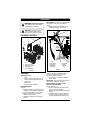
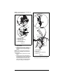
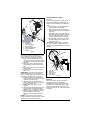
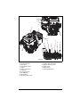
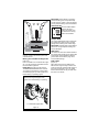
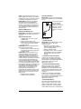
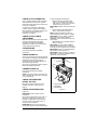
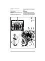
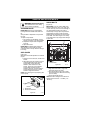
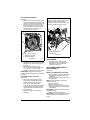
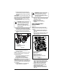
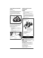
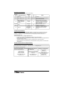
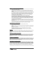
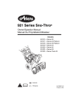
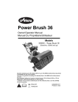
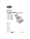
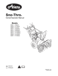
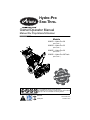
7. Remove attachment drive belts from
engine sheave (it may be necessary to
turn engine sheave using recoil starter
handle).
IMPORTANT: To avoid bending bottom cover
when tipping unit apart, support handlebars
firmly or tip unit up on housing and remove
bottom cover by removing six cap screws
before separating unit.
8. Support Sno-Thro frame and housing.
CAUTION: Always support SnoThro frame and blower housing
when loosening the cap screws
holding them together. Never
loosen cap screws while unit is in
service position.
WARNING: AUGER / IMPELLER
MUST STOP within 5 seconds
when attachment clutch lever is
released or unit damage or serious
injury may result.
6. Reconnect chute crank and secure with
spring clip. Reconnect chute lock cable
and deflector cable.
7. Replace chute gear cover.
8. Replace belt cover and tighten
hardware.
TRACTION DRIVE BELT
REPLACEMENT
9. Remove hex bolts securing housing to
frame (one on each side). Tip housing
and frame apart on pivot pin (Figure 30).
10. Remove attachment drive belts from
attachment pulley (hold brake away from
belts).
2
(Figure 31)
NOTE: Replacement will be easier with
housing and frame tipped apart and bottom
cover off.
1. Remove attachment drive belts (see
Remove old attachment drive belts on
page 28).
2. Remove hairpin attaching traction cable
to the idler arm, and disconnect the
cable. (Figure 31).
3
2
7
1
4
1
3
1. Pivot Pin
2. Housing Cap Screws
3. Belt Cover
5
Figure 30
6
Install new attachment drive belts
1. Place new attachment belts onto
attachment pulley.
NOTE: Holding down the attachment clutch
lever will make it easier to reconnect the
housing and frame.
2. Tip housing and frame back together
and secure with hex bolts.
3. Place belts onto engine sheave.
4. Reposition and secure belt fingers.
IMPORTANT: With clutch lever engaged, belt
finger on the side opposite the belt idler
should be less than 1/8 in. (3 mm) from belts,
but not touching the belts. Adjust belt finger
as necessary.
5. Check adjustment. See Check Belt
Finger Clearance on page 28.
EN - 29
1.
2.
3.
4.
5.
6.
7.
Traction Drive Belt
Engine Sheave
Belt Finger
Attachment Belts Idler
Attachment Pulley
Attachment Idler Adjustment Nut
Traction Belt Idler
Figure 31
3. Pull idler away from traction drive belt
and remove belt from stationary idler
pulley, engine sheave and transmission
pulley. (It may be necessary to turn
engine pulley using recoil handle.)
4. Install new traction drive belt onto
transmission pulley, stationary idler
pulley and engine sheave.
5. Replace attachment drive belts (see
Install new attachment drive belts on
page 29).