1
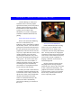
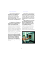
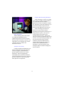
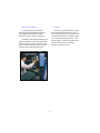
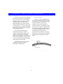
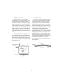
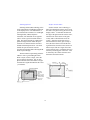
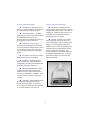
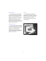
Contents
Section 1.
A Glance at Touch . . . . . . . . . . . . . . . . . . . . . . . . . . . . . . . . . . . . . . . . . . . . . . . . . . .5
An introduction to touch technology: what it is, why and when it is used, and
the reasons for touch technology’s expansion into mainstream computer
applications.
Why Touch Technology? . . . . . . . . . . . . . . . . . . . . . . . . . . . . . . . . . . . . . . . . . . . . . .5
The Benefits of Touch Technology . . . . . . . . . . . . . . . . . . . . . . . . . . . . . . . . . . . . . .6
Do I Need Touch Technology?. . . . . . . . . . . . . . . . . . . . . . . . . . . . . . . . . . . . . . . . . .9
Section 2.
Where is Touch Being Used? . . . . . . . . . . . . . . . . . . . . . . . . . . . . . . . . . . . . . . . . . .10
A description of where touch technology is being used and why it’s successful
in these applications.
Section 3.
Types of Touch Technologies. . . . . . . . . . . . . . . . . . . . . . . . . . . . . . . . . . . . . . . . . .14
Six touch technologies are discussed, including their operating theories.
Section 4.
Evaluating Touch Technologies . . . . . . . . . . . . . . . . . . . . . . . . . . . . . . . . . . . . . . . .18
A description of the physical and environmental factors critical to evaluating
any touch technology. Comparison charts include manufacturer’s system
specifications and environmental considerations.
Touch Technology Physical Factors. . . . . . . . . . . . . . . . . . . . . . . . . . . . . . . . . . . . .18
Environmental Factors . . . . . . . . . . . . . . . . . . . . . . . . . . . . . . . . . . . . . . . . . . . . . . .20
Touch System Comparison Chart . . . . . . . . . . . . . . . . . . . . . . . . . . . . . . . . . . . 22 - 23
Section 5.
Comparison of the Touch Technologies . . . . . . . . . . . . . . . . . . . . . . . . . . . . . . . . . .24
The advantages and disadvantages of each touch technology are compared.
Section 6.
Touch Products Design . . . . . . . . . . . . . . . . . . . . . . . . . . . . . . . . . . . . . . . . . . . . . . .30
Design considerations and how they apply to your touch application.
Mechanical Considerations. . . . . . . . . . . . . . . . . . . . . . . . . . . . . . . . . . . . . . . . . . . .30
Physical Attributes . . . . . . . . . . . . . . . . . . . . . . . . . . . . . . . . . . . . . . . . . . . . . . . . . .32
Section 7.
Programming Considerations . . . . . . . . . . . . . . . . . . . . . . . . . . . . . . . . . . . . . . . . . .33
Hardware and software interface options, along with special design
considerations.
Section 8.
Glossary . . . . . . . . . . . . . . . . . . . . . . . . . . . . . . . . . . . . . . . . . . . . . . . . . . . . . . . . . .37
For More Information . . . . . . . . . . . . . . . . . . . . . . . . . . . . . . . . . . . . . . . . . . . . . . . .39
Other Carroll Touch Publications . . . . . . . . . . . . . . . . . . . . . . . . . . . . . . . . . . . . . . .39
3
Copyright © 1998 Carroll Touch
All rights reserved. No part of this book may be reproduced in any form without prior written
permission from Carroll Touch. Making copies of any part of this book for any purpose other than
your own personal use is a violation of United States copyright laws. For information, contact
Carroll Touch, 2800 Oakmont Drive, Round Rock, Texas 78664.
4
Section 1.
A Glance at Touch
Why Touch Technology?
them by the general public as well. From
what started as a widespread fear of computers has now emerged widespread computer savvy - a world of employers,
consumers, and students that consider
computers to be a normal part of daily life
and expect them to be fast and easy to use.
It is this trend that has made touch technology more popular than ever. Not only will
touch input devices work in installations
where no other form of input is practical,
but the use of graphical icons and images
that is typical in
touch applications
results in a system
that anyone can
look at and use
immediately - with
no learning curve or
complicated
instructions to follow.
In the past, most computers resided in
laboratories and were operated by trained
professionals. Now computers are used
everywhere, from train stations to fast
food restaurants, and used by people from
all walks of life. Children use computers.
Grandparents use computers. Even animals, like dolphins at a research facility in
Maui, use computers. Evolving from the
bulky desktop computer and its assorted
peripheral hardware, today’s computers
come in all different shapes and
sizes. Devices
such as touch
screens and single-board computers have made it
possible to mount
computers in
places that were
previously
unthinkable, like
in gas pumps or
shopping carts. (Imagine a consumer
using a mouse with the computerized
shopping cart, or a keyboard attached to
the gas pump!) Touch input devices fit
discreetly over any size display and
occupy no additional space, making them
perfectly suited to the current trends in
computers.
There simply is
no easier way to
access a computer
than touching it. It is natural and intuitive
for people all over the world to point to an
object, transcending the barriers of language and culture that may be encountered
with other input devices.
It is not only computers that have
evolved over time, but the perception of
5
The Benefits of Touch Technology
There are many benefits to touch technology that include design advantages as
well as advantages to the user.
n
Increased Design Opportunities
Outer space or under water - the limitations of traditional input devices no longer
apply when using touch technology. Touch
screens fit directly onto the surface of a display or around the perimeter of it, so there is
no need for concern about enough space or
surface area to accommodate a peripheral
device. This has created all new applications
such as in-vehicle controls and mobile communications, and greatly increased the system mounting options for designers.
images on an illuminated display is far easier
and more accurate than attempting to use a
keyboard in the dark - especially if you’re
driving.
Many types of touch technology are also
extremely resistant to environmental conditions and substances that are destructive to
traditional input devices, thus creating applications for computers in places that were
previously not practical. Severe industrial
environments, engine rooms, and automotive
repair bays are examples of applications that
are best suited for touch input because of the
likely damage other input devices would sustain.
n
Immediate Response
Unlike other input devices such as a
mouse, trackball, or joy stick, the user does
not have to coordinate hand movements
between the movement of the input device
and the corresponding movement of the cursor on the screen. Once the user has made
the selection, the target can blink or switch to
reverse video so the user can see immediately that the input has been accepted.
Touch technology also solves other
problems encountered with traditional input
devices, such as equipment that is used at
night or in dark environments. Examples
include in-vehicle controls, cockpits, or
security/surveillance equipment. Touching
6
n
Simplifies Complex Systems
fused by too much information at a time.
Because only valid selections are offered on
the screen, the user is not confused by
options that do not correspond to the task at
hand.
Where an extensive database is
involved, touch systems simplify information by limiting the number of options or
amount of data displayed at any one time.
Touch targets provide step-by-step, fail-safe
sequences to guide the user through a complex set of procedures. This greatly simplifies medical diagnostics applications, for
example, where voluminous databases need
to be accessed quickly and easily. Touch targets are also useful in simplifying process
control applications involving a large number of buttons or switches, and for applications where system contents require
protection from unauthorized entry.
n
Everyone’s an Expert
Inexperienced computer users are frequently as intimidated by the input device as
they are of the computer. For some people,
the image of the traditional desktop computer with keyboard is not only uninviting,
they may go out of their way to avoid it. For
designers of systems used in retail sales,
public information, or self-service equipment, this is obviously a highly undesirable
reaction.
Graphical interfaces designed for touch
devices are usually designed to display the
fewest possible choices within each screen,
so that users are not overwhelmed or con-
Touch technology is extremely effective
in abating the fears of inexperienced users.
A touch-active display in a console with an
attractive graphical interface doesn’t look
like a computer anymore. For most inexperienced computer users, that alone is enough
to try it out. With the addition of other
appealing features, such as music, using a
touch active computer to obtain information
or make a purchase can be a comfortable
experience for even the most cynical user.
Unlike any other input devices, you
don’t need to practice or get used to using a
touch system - everyone is an expert the first
time.
7
n
Graphical User Interfaces
Graphical user interfaces support the use
of graphics, color, and sound to capture and
sustain a user’s interest. They are also intuitively easy to understand, allowing designers to create systems that can be operated
easily by users with all different levels of
computer experience or literacy.
Graphical touch targets can be displayed
on much smaller displays than what is
needed to display written instructions.
Many new uses for small displays, such as
in computerized golf carts and shopping
carts, have emerged as a result.
Most touch application screens, such as this CD Sampler,
are designed to be so intuitively easy to understand that no
instructions are necessary.
n
Easily Updated
Unlike fixed control panels, there are no
physical switches in a touch panel. Touch
targets are reconfigurable and can be easily
updated as required.
8
Do I Need Touch Technology?
n
Touch technology is especially
beneficial if...
n
Touch technology is ideally suited for
creating a simple interface to an otherwise
complex system. One example is an automobile diagnostics computer. This type of
computer, with a traditional interface, may
be frustrating to mechanics with no prior
computer experience and costly to their
employers during the learning curve. Graphical touch interfaces can reduce or eliminate
both the frustration and the learning curve by
guiding the mechanic through the process
with a series of touch-active menus. (In
addition, many touch screens are impervious
to grease and other substances that would
damage a keyboard.)
Space is critical
Touch technology is an excellent alternative when the device is too compact to
make a keyboard or mouse practical. Handheld computers or personal digital assistants
(PDAs) are examples of applications that are
not suitable for use with traditional detached
input devices.
n
Time is critical
Applications such as in-vehicle controls
can be dangerous if the user’s eyes are
diverted too long. Other applications, such
as automatic ticket-dispensing machines in
train stations or sports complexes, can accumulate long lines unless they are intuitively
easy to use. Touch systems eliminate the
time it takes for the user to switch back and
forth between a display and the input device,
and the graphical user targets minimize or
eliminate the need for the user to read
instructions.
n
Simplification is critical
Another example is in laboratories. A
chemist could use a blood analyzer program
to run a variety of diagnostic tests and perform management functions. A series of
touch-active menus can easily guide the
chemist through the necessary sequence of
tests required in a fraction of the time that it
would otherwise take the chemist to key in
data.
Accuracy is critical
Touch technology is extremely useful
when fast and accurate system interaction is
required. For example, an air traffic controller can touch a radar image on a display
rather than typing data to receive additional
information on a particular aircraft.
9
Section 2.
Where is Touch Being Used?
Touch technology is widely used
around the world. The most popular
applications include point-of-sale/point of
purchase, public information, medical
instrumentation, mobile and hand-held
systems, process control, office
automation, test systems, training and
simulation, industrial automation, and
gaming.
Point-of-Sale/Point-of Purchase
Point-of-sale (POS) merchandising
has been revolutionized by new
technology such as automated accounting
and inventory control. One of the fastest
growing areas for touch-activated systems,
this new generation of POS systems have
graphical user interfaces that are fast and
easy to use, require little time to learn, and
virtually eliminate many of the timeconsuming and sometimes costly errors
that occur with operating and closing out
cash registers. As soon as a sales clerk
touches an icon, the cost is added to a
running total and the inventory and sales
accounting takes place automatically.
Several tasks are accomplished with one
touch, accurately and efficiently.
Interactive Kiosks/Multimedia
Public information kiosks are being
used in every type of business: retail,
transportation, service industry, and
recreational, with more being added all the
time. Touch systems are an integral part
of interactive kiosks and account for much
of the success of this market because they
can be used by anyone, regardless of
language, education, socioeconomic or
cultural background.
Because interactive kiosks must be
intriguing and fast-moving enough to
sustain the user’s interest, the screens must
be fast, colorful, and entertaining. The
graphical user interfaces used with touch
systems promote creative screen designs
and are easily combined with music to
achieve captivating results.
A POS system with a touch interface
is particularly useful in applications such
as restaurants, where a busy waitstaff can
quickly enter orders with one hand while
carrying food or dishes in the other.
Orders are routed automatically to the
kitchen, and a bill is automatically
generated by touching a print button on
the screen.
10
Medical Instrumentation
Process Control
Touch input allows the integration of
many functions into a single piece of
equipment, thus saving valuable lab or
surgery space. Plus, several touch
technologies can be completely sealed,
operated with gloved fingers, and are
unaffected by substances that may be present
on a surgical glove (such as ultrasound gel).
Traditionally, the operator interface for
process control systems consisted of banks
of discrete controls, switches and indicators.
Touch technology allows you to replace such
an interface with a flexible, reconfigurable
control panel that displays only the controls
and indicators that are relevant to a specific
process.
Unlike other input devices, some of the
more rugged touch technologies are not
degraded by a harsh environment. They
perform consistently under even the most
severe conditions, unaffected by
environmental factors such as vibration or
temperature extremes - conditions often
found in the process control environment.
Some touch technologies can be sealed,
making them impervious to dirt, water,
airborne particulates and other contaminants.
Mobile and Hand-Held Systems
As computers become commonplace in
applications such as warehouse inventory
control, route accounting for freight
movement, trade or commerce, and other
industries that require small and portable
equipment, the need for practical alternatives
to keyboards is increasing. Touch devices
are the ideal alternative in these applications
because they occupy no additional space and
many will tolerate the adverse conditions
unique to a mobile device, such as being left
in a hot cab of a truck, dropped on a
warehouse floor, or splashed with beverages
and other corrosive substances. Touch input
devices open new opportunities for mobile
applications as well. Whereas a keyboard is
obviously a dangerous and unpractical
device to use for driver controls in an
automobile or other vehicle, illuminated
graphical user interfaces can be safely
operated while driving, as well as at night or
in the dark.
11
Computer-Based Training/Simulation
Touch technology is used in everything
from reading programs to flight simulators.
It’s the interface of choice in such
applications, because it simplifies computer
use. Remember, with touch technology, you
can limit the number of options or the
amount of data displayed at any one time.
Touch technology also allows the
trainees to be given a more realistic
reproduction of the operator interface they’re
being trained to operate. The layout of
control buttons and switches can be
reproduced almost exactly. Trainees not
only see a realistic reproduction of the actual
interface, an obvious training advantage, but
they also physically interact with the
simulator, giving them added memory
reinforcement of where the controls are
located. This combination has two
advantages: long-term retention of the
training is improved, and the training time
itself is reduced.
Office Automation
Touch technology allows the controls
for complicated equipment such as
sophisticated copiers to be more compact
than is possible with discrete controls. Plus,
touch allows you to integrate more control
capabilities than are possible with
mechanical controls.
Automatic Test Systems
Complex computerized diagnostics now
used to troubleshoot and repair equipment
such as jet engines or automobiles are
greatly simplified with the use of touch
technology. The more rugged touch
technologies can be used in environments
such as an automobile service bay, where the
presence of grease, oil, and water makes
other input devices impractical.
12
Industrial Automation
Gaming
By eliminating the keyboard in a
distracting and often harsh environment,
touch simplifies the human/machine
interface for large, complex equipment.
Interactive gaming systems designers
have found that touch allows the user to
concentrate on the activity presented on the
screen without having to coordinate handeye movements of the input device. The
intuitive nature of touch complements the
selection-based activity required by
interactive gaming systems.
In addition, some touch technologies are
rugged enough to be used in environments
such as steel mills and oil refineries where
the user must wear heavy gloves to protect
against caustic chemicals and vapors.
13
Section 3.
Types of Touch Technologies
In order to select the touch technology
that best fits your needs, it is important to
take a brief look at how each technology
functions. There are six basic types of
touch technology: capacitive overlay,
guided acoustic wave, resistive overlay,
scanning infrared, near field imaging, and
surface acoustic wave. Each type of touch
technology has attributes that are desirable
for specific applications.
Capacitive Overlay
Capacitive overlay technology uses a
glass overlay with a thin metallic coating
over the surface of the display screen. The
user must touch the overlay with a
conductive stylus, such as a finger, to
activate the system. Touching the overlay
surface causes a capacitive coupling with
the voltage field, drawing a minute amount
of current to the point of contact. The
current flow from each corner is
proportional to the distance to the finger
and the ratios of these flows are measured
by the controller and used to locate the
touch.
All types of touch systems are
attached to a display unit, whether a
terminal, CRT, flat panel display, static
graphic, or combination of flat panel
display and static graphic. The differences
between the technologies lie largely in the
way the touch is detected and the method
used to process the touch data.
The following sections give a short
introduction to the types of touch
technologies available today.
14
Guided Acoustic Wave
Resistive Overlay
Guided acoustic wave is based on
transmitting acoustic waves through a glass
overlay placed over the display surface. A
transducer mounted on the edge of the glass
emits an acoustic wave. The wave packet
travels along the reflector array, is redirected
across the overlay to the reflecting edge, and
returns to the array where it is reflected back
to the transducer. The first reflector will
send a signal back first, then the second, and
so on.
Resistive overlay technology consists of
a glass overlay with a thin metallic coating,
over which a layer of polyester is placed.
The polyester layer has a similar metallic
coating on the interior surface. Tiny spacer
dots of non-coated polyester prevent the two
surfaces from contacting each other. A final
hard coating is usually applied to the
external surface of the polyester to reduce
damage from sharp styli. A current is pulsed
through the glass overlay along the x-axis
and then the y-axis. When a finger or other
stylus presses the two layers together, the
current is shunted and the control electronics
determine the coordinates of the touch
location, which are then transmitted to the
host computer.
When a stylus such as a finger comes
into contact with the wave, it attenuates the
wave motion by absorbing part of the wave.
Control electronics detect the location of the
dip in the wave amplitude, thus determining
the touch position.
15
Scanning Infrared
Surface Acoustic Wave
Scanning infrared (IR) technology relies
on the interruption of an IR light grid in front
of the display screen. The touch frame or
opto-matrix frame contains a row of IR-light
emitting diodes (LEDs) and photo
transistors, each mounted on two opposite
sides to create a grid of invisible infrared
light. The frame assembly is comprised of
printed wiring boards on which the optoelectronics are mounted and is concealed
behind an IR-transparent bezel. The bezel
shields the opto-electronics from the
operating environment while allowing the IR
beams to pass through.
Surface acoustic wave technology is
based on transmitting acoustic waves across
the surface of a glass overlay placed over the
display surface. A transducer mounted on
the edge of the glass emits the acoustic wave,
which travels on the surface of the glass
overlay and is reflected back across the
overlay. Since the speed of the wave is
known and the size of the glass overlay is
fixed, the first reflector will send the first
signal back first, then the second, and so on.
When a stylus such as a finger comes into
contact with the wave, it attenuates the wave
motion by absorbing part of the wave. This
is detected by the control electronics and
determines the touch location.
The IR controller sequentially pulses the
LEDs to create a grid of IR light beams.
When a stylus, such as a finger, enters the
grid, it obstructs the beams. One or more
photo transistors detect the absence of light
and transmit a signal that identifies the x and
y coordinates.
16
Near Field Imaging (NFI)
NFI is based on a proprietary topology/
imaging technology. The sensor layout is a
piece of glass coated with an Indium Tin
Oxide (ITO) pattern on the front side and
complete ITO coating on the back side. The
front of the sensor is optically laminated to a
layer of passive glass, typically .043” thick.
An excitation waveform is supplied to
the conductive sensor and generates an
electrostatic field which becomes the
baseline. When a finger or other conductive
stylus comes into contact with the sensor, a
change occurs in the electrostatic field. The
control electronics then subtract the change
from the baseline and determine the peak
imaging shape and location to establish the
x- and y-axis coordinates of the touch
location.
17
Section 4.
Evaluating Touch Technologies
Each touch input technology has both
advantages and disadvantages. These
advantages and disadvantages consist of
physical factors associated with the
technology, and with each technology’s
ability to withstand the impact of factors
occurring in the application’s
environment.
Transmissivity
Another variable to consider is image
clarity. The display image can be affected
by placement of any material between the
display image and the viewer’s eye. All
systems that require an overlay over the
display screen such as resistive,
capacitive, surface acoustic wave, near
field imaging, and guided acoustic wave
involve some visual obstruction between
the operator and the image on the screen.
Transmissivity is defined as the
percentage of light from a display
remaining after passing through a material.
Touch Technology Physical Factors
Factors to consider include:
resolution, transmissivity, response time,
stylus type, calibration, integration, and
reliability. Specifications covering each of
these factors are given in the Touch
System Comparison Charts (pages 22-23)
for each technology.
Response Time
Response time is an important
consideration when evaluating touch
technologies. The faster a touch system
can respond to a user’s input, the better.
Response time is defined as the time
required for the touch system to locate the
touch and transmit the touch location to
the host system. However, several factors
contribute to the response time of the
complete touch application: touch system
response time, host processing speed,
access to the host electronics and
application software. Response times
specified in the Touch System
Comparison Charts relate to the response
time of the touch system only.
Resolution
Touch system resolution refers either
to the number of touch active points, or to
the physical spacing between the adjacent
touch coordinates. When considering the
resolution of the touch system, it is
important to keep in mind the touch
system’s intended application. For many
applications, such as control panels, public
access or computer-based training, fine
resolution is not required. In some
applications, such as signature
verification, a very high touch system
resolution is desired.
18
Stylus Type
Integration
A stylus is an object or instrument used
to activate a touch system, such as a finger,
pen, gloved hand, etc.
Integration is the process of attaching
the touch system to the display. Invasive
integration requires the disassembly of the
display to attach the touch system.
Typically, this type of integration results in
voiding the manufacturer’s warranties and
FCC certification. This type of integration
requires a skilled technician and usually
takes from 15 to 90 minutes.
Calibration
Calibration is the process of adjusting
the active area of a touch system by
physically modifying the calibration
parameters of the touch (i.e., adjusting
potentiometers, setting EEROM parameters,
etc.). Although all touch systems require an
initial calibration during installation, only
systems that are subject to drift (where touch
targets gradually move away from the
desired locations) require routine or periodic
calibration.
Noninvasive integration does not
require disassembly of the display. This type
of integration can typically be done by
anyone and takes less than ten minutes.
Reliability
Reliability of a touch system refers to
how long it is expected to last before it fails.
Touch systems with polyester or conductive
coatings will fail after an anticipated number
of touches wear the coatings off. The
reliability of other touch systems that do not
wear out with use is measured in mean time
between failures (MTBF). This number is
normally derived by calculating the average
life expectancy of the electronic components
built into the touch system.
n Capacitive and resistive overlay
systems are subject to drift and require
calibration, which generally consists of
adjusting the offset and scaling parameters to
make the touch area equal to, or greater in
size, than the display image.
n Surface acoustic wave, scanning
infrared, and guided acoustic wave are not
subject to drift and do not require calibration
after installation.
19
Environmental Factors
Dust and Dirt
The ability of the touch system to
withstand environmental conditions is an
important factor when evaluating touch
technologies.
An excessive buildup of dust, dirt, or
other contaminants can adversely affect the
performance of some touch technologies.
n Capacitive overlay, scanning
infrared, and surface acoustic wave
technologies will operate with low to
moderate accumulations of dust, dirt, and
other contaminants. Excessive levels will
affect performance.
Sealability
Sealability is the ability to seal a touch
system, including display electronics, from
dirt, liquids, etc. If the system is going to be
located in an area where contaminants are
present, sealability can be an important
consideration. In environments such as
surgical operating rooms, sealability is
critical.
n Guided acoustic wave, resistive
overlay, and near field imaging touch
technologies are not affected by dust, dirt, or
other contaminants.
All touch technologies can be sealed to
meet NEMA 12 requirements that a system
be operational after accidental splashing or
cleaning.
Chemicals
All touch technologies are unaffected by
general purpose cleaning solutions.
However, some materials used in the various
touch technologies can be attacked by
certain chemicals.
Capacitive overlay, guided acoustic
wave, resistive overlay, near field imaging
and scanning infrared technologies can be
sealed to meet NEMA 4 requirements, which
require a system to operate, even after
exposure to hose-directed water.
n A resistive overlay touch system
has an exposed polyester overlay.
Chemicals that attack polyester should not
be used.
n A scanning infrared touch system
has exposed polycarbonate bezels.
Chemicals that attack polycarbonate, such as
petroleum-based chemicals, should not be
used. More resistant materials are available
for construction of special IR touch systems,
but unless specified, they are not widely
used.
Durability and Resistance to Vandalism
Durability is the ability to withstand
millions of touches over many years.
Resistance to vandalism is the ability to
resist defacement - scratching, breaking,
theft, etc.
20
Vibration and Shock
Temperature, Humidity and Altitude
Vibration and shock affect each touch
technology differently, ranging from no
effect to severe equipment damage. This is
an important consideration if the application
is in an aircraft, train, ship, or other moving
device. Equipment used in industrial
applications can also be exposed to
significant vibration or shock.
The temperature, humidity and altitude
of the touch application environment have an
effect on the operation and durability of any
touch system. Plastics and electronics are
affected by temperature. Humidity enhances
the corrosion of circuitry. Altitude affects
the dissipation of the heat generated by
functioning electrical circuitry.
It is safe to say, however, that the impact
of these environmental factors on the touch
systems will be less (or at least no greater)
than their impact on the circuitry of the
display or flat panel to which the touch
system is integrated. Specific data regarding
the impact of these environmental factors
may be found in the technology comparison
charts.
Ambient Light
Ambient light is the level of visible and
invisible light in the area surrounding a
touch technology installation. Most
technologies are not affected by ambient
light. Infrared technologies can be adversely
affected depending on the manufacturer and
packaging of the infrared touch system.
Ambient light levels found in well-lit indoor
environments do not present any problems.
21
22
1024 x 1024
physical, no z-axis
21,904 points/
square inch
physical, plus z-axis
256 x 256 to
4096 x 4096
physical,
no z-axis
0.25” physical,
0.125” logical,
no z-axis
0.030” physical,
plus z-axis
Near Field Imaging
Guided
Acoustic Wave
Resistive
Overlay
Scanning
Infrared
Surface
Acoustic Wave
* Manufacturer’s published data.
1024 x 1024
physical, no z-axis
Capacitive Overlay
Resolution and Zaxis
92%
Tactile activation,
no parallax,
53 - 59 ms
Proximity activation, parallax,
18 - 40 ms
Tactile activation,
no parallax,
13 - 18 ms
55-78%
100%
Tactile activation,
no parallax,
18 - 50 ms
Tactile activation,
parallax, 10 - 20 ms
Tactile activation,
no parallax,
15 - 25 ms
Requires soft,
energy-absorbing
stylus
Not subject to drift
Not subject to drift
Subject to drift.
Requires repetitive
calibration
No stylus limitation
No stylus material
limitation.
Minimum stylus
diameter 5/16”
Not subject to drift
Not subject to drift
Subject to drift.
Requires repetitive
calibration
Sensor Drift
and Calibration
Requires soft,
energy-absorbing
stylus
Requires conductive stylus.
Requires conductive stylus. Unable
to simultaneously
detect gloved and
ungloved finger
Activation, Parallax
Stylus Type
and Response Time
92%
85%
85 - 92%
Transmissivity
Touch System Comparison Chart*
Invasive. Optical
bonding required for
optimum display
clarity
Sensor - 50,000,000
touches per point.
Controller - 86,000 118,000 hours
MTBF
>138,000 hours
MTBF
Sensor - 2,000,000
touches per point.
Controller - 86,000 180,000 hours
MTBF
Invasive. Optical
bonding required for
optimum display
clarity
Invasive and
non-invasive
Sensor - Unlimited.
Controller >180,000 hours
MTBF
Sensor - unlimited.
Controller >180,000 hours
MTBF
Sensor - 20,000,000
touches per point.
Controller >186,000 hours
MTBF
Reliability
Invasive. Optical
bonding required for
optimum display
clarity
Invasive
Invasive and noninvasive. Optical
bonding required for
optimum display
clarity
Integration
23
NEMA 12
NEMA 4
Sensor is vulnerable to
scratches and
abrasions, glass
overlay can be broken
Not susceptible to
scratching, no overlay to
break, completely solidstate, no exposed parts
Difficult to scratch, glass
overlay is breakable
Resistive
Overlay
Scanning
Infrared
Surface
Acoustic Wave
* Manufacturer’s published data.
NEMA 12
NEMA 4
Difficult to scratch, glass
overlay is
breakable
Guided
Acoustic Wave
NEMA 12
NEMA 12
NEMA 4
NEMA 12
NEMA 4
Difficult to scratch,
glass overlay is breakable
Near Field Imaging
NEMA 12
NEMA 4
Difficult to scratch, conductive layer is subject
to wear, glass overlay is
breakable
Capacitive
Overlay
Not affected by general
purpose cleaning
solutions. Chemicals
that affect
polycarbonates should
not be used
Not affected by general
Will operate with
moderate dust and dirt, purpose cleaning
excessive accumulation solutions
may affect performance
Will operate with
moderate dust and dirt,
excessive accumulation
may affect performance
Not affected by dust and Not affected by general
dirt
purpose cleaning
solutions. Chemicals
that affect polyester
should not be used
Not affected by dust and Not affected by general
dirt
purpose cleaning
solutions
Not affected by dust and Not affected by general
dirt
purpose cleaning
solutions
Will operate with
Not affected by general
moderate dust and dirt, purpose cleaning
excessive accumulation solutions
will affect performance
Durability/ Resistance to NEMA Ratings,
Dust and Dirt Resistance Chemical Resistance
Vandalism
Moisture Resistance
Unaffected by
ambient light
Ambient Light
Tolerant of vibration,
glass overlay is
susceptible to shock
Unaffected by
ambient light
Tolerant of vibration and Varies by manufacturer
shock
Tolerant of vibration,
Unaffected by
glass overlay susceptible ambient light
to shock
Tolerant of vibration,
Unaffected by
glass overlay susceptible ambient light
to shock
Tolerant of vibration and Unaffected by
shock
ambient light
Tolerant of vibration,
thick glass overlay
moderately susceptible
to shock
Vibration
and Shock Resistance
Touch System Comparison Chart* (Continued)
0° to 50°C;
0 to 95% non-condensing
humidity;
altitude not specified
0° to 55°C;
0 to 95% non-condensing
humidity;
altitude not specified
0° to 50°C;
0 to 95% non-condensing
humidity;
15,000 ft. (4,500 m)
0° to 50°C;
0 to 95% non-condensing
humidity;
altitude not specified
0° to 50°C;
0 to 95% non-condensing
humidity;
altitude not specified
0° to 70°C
0 to 95% non-condensing
humidity;
30,000 ft. (9,000m)
Temperature, Humidity, and
Altitude
Section 5. Comparison of the Touch Technologies
n Sensor Drift/Calibration Capacitive overlay touch systems are
subject to drift, where the touch-active
zones move from the graphic targets
representing them. Periodic calibration is
required.
Having shared an overview of the
various touch technologies and the factors
that can affect their suitability for use in
various application environments, let us
compare each technology’s advantages
and disadvantages.
n Integration - Capacitive sensors
typically require an invasive installation to
maximize the display’s optical quality and
reduce the chance of breaking the glass
overlay. This invasive integration requires
disassembly of the display and
(optionally) permanent optical bonding of
the sensor to the display. Although flat
capacitive overlay sensors can be attached
to the exterior of the display, thereby
avoiding an invasive integration, optical
distortion and the possibility of breakage
are greatly increased. Mounting the flat
capacitive overlay sensor externally to
either a spherically or cylindrically curved
display will intensify parallax.
Capacitive Overlay Advantages
n Resolution - Capacitive overlay
systems can deliver a resolution of up to
4096 x 4096 touch points.
n Sealability - Capacitive overlay
system sensors can be sealed to the
display, preventing water and dirt from
penetrating the display’s inner electronics.
Capacitive overlay systems can be sealed
to meet NEMA 4 requirements.
n Flexibility - Capacitive overlay
sensors are adaptable to a wide range of
displays without expensive custom
designs.
n Environmental Resistance Capacitive sensors are a type of
mechanical switch, even though there is a
hard coating applied over the sensor
surface. Through repeated, heavy use, the
hard coating and metallic coating can be
worn off or abraded over time. Also, the
glass overlay is susceptible to breakage.
Capacitive Overlay Disadvantages
n Transmissivity - Capacitive
overlay systems typically have a
transmissivity of 85% to 92%. This can
adversely affect image quality, particularly
for high resolution video modes.
n Stylus Requirements - Capacitive
overlay touch systems require a
conductive stylus to operate. Materials
that will not conduct a current, such as a
pencil, fingernail, or insulated glove, will
not activate the system. Although a
capacitive system’s sensitivity can be
adjusted to activate with a thin cotton or
surgically gloved hand, it cannot recognize
a gloved and an ungloved hand using the
same sensitivity setting.
24
Guided Acoustic Wave Advantages
Guided Acoustic Wave Disadvantages
n Resolution - The resolution of
guided acoustic wave technology is
determined by how quickly the controller
can interpret signals sent by the touch sensor.
Typical resolution is 148 touch points per
linear inch (or 21,904 points per square
inch).
n Stylus Requirements - Guided
acoustic wave touch systems require a soft,
energy absorbing stylus to operate. A hard
stylus, such as a pen, will not absorb the
acoustic energy and will not be recognized
as a touch.
n Integration - Guided acoustic wave
touch systems typically require an invasive
integration to maximize the optical quality of
the display and reduce the chance of
breaking the glass overlay. This invasive
integration requires disassembly of the
display and (optionally) permanent bonding
of the sensor to the display.
n Calibration - Since the reflector
arrays determining the touch location are
fixed in one place, guided acoustic wave
systems are not subject to sensor drift. The
touch system needs only to be aligned with
its corresponding display.
n Z-axis - In addition to the typical x
and y coordinates, guided acoustic wave
systems can provide a z-axis component,
which is determined by the amount of
pressure applied to the sensor.
n Environmental Resistance - The
glass overlay of guided acoustic wave is
susceptible to breakage.
n Sealability - Guided acoustic wave
touch systems sensors can be sealed to meet
NEMA 4 requirements, preventing water and
dirt from penetrating the display’s internal
electronics.
n Transmissivity - Guided acoustic
wave touch systems typically have a
transmissivity of 92%.
25
Resistive Overlay Advantages
Resistive Overlay Disadvantages
n Resolution - Resistive overlay
touch systems can deliver resolution of up to
4096 x 4096 touch points.
n Transmissivity - Resistive overlay
touch systems have a transmissivity of 55%
to 78% due to multiple layers of different
materials found in the resistive overlay
sensor. They are also more susceptible to
glare and reflection than any other touch
technology. This can adversely affect image
quality, particularly for high resolution video
modes.
n Stylus Requirements - Resistive
overlay touch systems have no stylus
limitations.
n Flexibility - Resistive overlay
sensors are adaptable to a wide range of
displays without expensive custom designs.
n Sensor Drift/Calibration - Resistive
overlay touch systems are subject to drift,
where the touch active zones move from the
graphic targets representing them. Periodic
calibration is required.
n Sealability - Resistive overlay touch
systems can be sealed to NEMA 4
requirements, preventing water and dirt from
penetrating the display’s internal electronics.
n Integration - Resistive overlay
touch systems typically require an invasive
integration to maximize the optical quality of
the display and to reduce the chance of
breaking the glass overlay. This invasive
integration requires disassembly of the
display and (optionally) permanent optical
bonding of the sensor to the display.
n Environmental Resistance Resistive overlay sensors are a type of
mechanical switch, and will wear out after
extended use due to a breakdown of the
separation layer. The exposed polyester top
layer is susceptible to cuts, scratches, and
abrasions. Chemicals that attack polyester
must be avoided. Also, the glass overlay is
susceptible to breakage.
26
Scanning Infrared Advantages
Scanning Infrared Disadvantages
n Transmissivity - Because there is no
overlay covering the display, the transmissivity of infrared touch systems is 100%.
n Resolution - Scanning infrared
touch systems typically provide a resolution
of eight touch points per inch. This does not
usually pose a problem when using a stylus
larger than 5/16” in diameter and touch
targets larger than 1/2” square.
n Stylus Requirements - Scanning
infrared touch systems require that the stylus
have a minimum diameter of 5/16”.
However, there are no limitations on the type
of material the stylus is made from.
n Parallax - Parallax occurs when a
touch is detected while the stylus is still
some small distance from the surface of the
display. For scanning IR touch systems,
parallax occurs because the invisible grid of
IR beams can be interrupted before actual
contact is made with the display. The
amount of parallax is dependent on the type
of integration and display type. Typically,
the flatter the display face, the lower the
amount of parallax.
n Calibration - Since the optoelectronics determining the touch location
are fixed in one place, infrared touch systems
are not subject to sensor drift. They need
only to be aligned with the corresponding
display.
n Integration - Non-invasive scanning
infrared touch systems are available.
n Sealability - Scanning infrared
touch systems can be sealed to NEMA 4
requirements, preventing water and dirt from
penetrating the display electronics.
n Environmental Resistance - Since
scanning infrared touch systems do not
require an overlay (which can be broken),
they are less vulnerable to vandalism. Also,
they are relatively immune to shock and
vibration.
n Solid State - Infrared touch systems
are solid state technology and have no
moving mechanical parts. As such, they
have no physical sensor that can be abraded
or worn out with heavy use over time.
27
Near Field Imaging Advantages
Near Field Imaging Disadvantages
n Resolution - Near field imaging
touch systems can deliver a resolution of up
to 1024 x 1024 touch points.
n Transmissivity - Near field imaging
touch systems typically have a transmissivity
of 85%, resulting in some degradation of
image color and optical quality.
n Calibration - Near field imaging
systems are not subject to sensor drift. The
touch system needs only to be aligned with
its corresponding display.
n Stylus Requirements - Near field
imaging touch systems require a slightly
conductive stylus to operate. Materials that
will not conduct a current, such as a pencil,
will not activate the system.
n Sealability - Near field imaging
touch systems can be sealed to NEMA 4
requirements, preventing water and dirt from
penetrating the display’s internal electronics.
n Integration - Near field imaging
touch systems require an invasive
integration, which requires disassembly of
the display and permanent optical bonding of
the sensor to the display.
n Environmental Resistance - Near
field imaging sensors are constructed of
reinforced glass that is highly impactresistant.
n Parallax - Near Field Imaging touch
systems have some degree of parallax.
28
Surface Acoustic Wave Advantages
Surface Acoustic Wave Disadvantages
n Resolution - The resolution of
surface acoustic wave technology is
determined by the physical placement of the
reflector arrays. Typical resolution is 33
touch points per inch.
n Stylus Requirements - Surface
acoustic wave touch systems require a soft,
energy-absorbing stylus to operate. A hard
stylus, such as a pen, will not absorb the
acoustic energy and will not be recognized
as a touch.
n Calibration - Since the reflector
arrays determining the touch location are
fixed in one place, surface acoustic wave
systems are not subject to the phenomenon
of sensor drift. The touch system needs only
to be aligned with its corresponding display.
n Integration - Surface acoustic wave
touch system sensors typically require an
invasive integration to maximize the optical
quality and to reduce the chance of breaking
the glass overlay. This invasive integration
requires disassembly of the display and
(optionally) permanent optical bonding of
the sensor to the display.
n Z-axis - In addition to the typical x
and y coordinates, surface acoustic wave
systems can provide a z-axis component,
which is determined by the amount of
pressure applied to the sensor.
n Sealability - Surface acoustic wave
touch systems cannot be sealed to NEMA 4
requirements and are susceptible to direct
exposure to water, dirt and other corrosives.
n Flexibility - Surface acoustic wave
touch systems are adaptable to a wide range
of displays without expensive custom fees.
n Environmental Resistance - The
glass overlay of the surface acoustic wave
touch system sensor is susceptible to
breakage. An accumulation of liquids,
grease, dirt, etc., will absorb the acoustic
wave, rendering the system nonfunctional.
n Transmissivity - Surface acoustic
wave touch systems typically have a
transmissivity of 92%.
29
Section 6. T o u c h P r o d u c t s D e s i g n
To achieve the benefits of human factors
in product design, the systems integrator
must realize that the full potential and
advantages of touch input require attention
to many interrelated considerations. Such
considerations are mechanical and physical
attributes, and programming considerations.
Mechanical Considerations
Display Selection
Selecting the computer display is one of
the major decisions affecting the cost of the
complete touch system. Today, the display
choices include both flat panels and CRTs.
Flat panel displays tend to present the fewest
mechanical design concerns for touch
systems, while CRTs typically require some
degree of mechanical design compensation
to correct for the curvature of the display
surface. As a general rule, touch
applications that require a large number of
targets on a single screen should move to a
larger display size.
Touch System Integration
Touch system designers must choose
which type of integration best suits their
applications, invasive or noninvasive. An
invasive integration typically requires that
the display be disassembled. This is very
time consuming and may void factory
warranties of the display. Noninvasive
integrations require very little time to
assemble and will not affect manufacturers’
warranties. Maintenance is simplified as
well.
30
Space Constraints
Sealing
Many touch systems will be located in
areas where space is limited. Flat panels
require very little space, while CRTs tend to
be bulky. The amount of physical space
required for the touch system varies for the
different touch technologies. The type of
integration selected can also affect the
amount of space required to hold the system.
Invasive integrations tend to use less space
than noninvasive integrations.
Depending on the environmental
conditions, the touch system may require
different degrees of sealability. Applications
that may require special consideration are
industrial/process control, medical
environments, point-of-sale, and outdoor
touch applications.
Environmental Factors
Different touch systems are designed to
operate in a wide spectrum of environmental
conditions. When designing a touch-based
system, items to consider would be
sealability, durability, reliability, and
vulnerability to vandalism. Specific details
on these environmental considerations are
found in Sections 4 and 5.
31
Physical Attributes
Most touch systems provide features
such as multiple operating and reporting
modes, improved software resolution, fault
tolerance and diagnostics. The number and
type of features required by a technology
depend on the amount of control needed by
the designer’s application. Touch systems
can be programmed to detect multiple styli,
calculate the size and center of the stylus,
reject a stylus that is larger or smaller than
the specified limits, or require that the stylus
remain in the touch-active area for a
specified amount of time before the touch is
considered a valid hit.
Aesthetics
System manufacturers considering the
inclusion of touch are understandably
concerned with aesthetics. The system must
not only meet the technological
requirements, but must also look attractive.
System Capabilities
The system designer must match the
touch system’s application considerations
with the touch system’s capabilities. Factors
to be considered include glare,
transmissivity, resolution, stylus types, and
aesthetics. For instance, systems that require
high quality graphics would gravitate
towards those touch technologies with the
best transmissivity and the least glare.
Applications requiring handwriting
recognition would need those technologies
with the highest resolution.
Another operating feature available with
some touch technologies is the capability to
report a z-axis coordinate, which measures
the amount of pressure applied to the sensor.
Typically, the harder the user presses on the
sensor, the higher the z-axis value. This zaxis coordinate is often used to emulate the
mouse button events. This is done by
comparing the z-axis coordinate to the
threshold value.
Another consideration would be the type
of stylus encountered in the specific
application. The touch technology selected
for the application environment must be
capable of recognizing the type of stylus
used in the application.
32
Section 7. Programming Considerations
Of prime consideration to the
applications programmer is the interaction or
communication between system hardware
units, the system software packages, and the
vital interface between the touch application
and the user.
Touch vendors have proprietary
software interface protocols unique to their
touch systems. All of the touch vendors’
software protocols report an x and y
coordinate; some technologies permit the
reporting of a z coordinate as well.
Hardware Interface Options
Direct Interface Method
Touch systems are designed to interface
with the host in a variety of different
configurations.
In the direct interface method, the touch
application communicates directly with the
touch system using the proprietary interface
protocol of the touch system.
One configuration involves communicating with the host system through a serial
port. Examples include the RS-232 and RS422 protocols.
Software Drivers
Software drivers are available from
touch vendors that assist the touch
application developer in interfacing to the
touch system. These drivers usually provide
calibration and scaling support, and
communicate with the touch system using
the touch vendor’s proprietary interface
protocol, and with the touch application via a
simple application program interface (API).
Another configuration involves parallel
communication via a bus standard.
Examples include ISA/EISA, microchannel,
and PC/104TM.
Another interface method uses the
mouse port. In this method, the touch
system is connected to the host computer’s
mouse port and uses either a standard mouse
interface protocol or a proprietary touch
system interface protocol.
Another interface configuration
involves the use of daisy-chained input
devices, such as the Apple Desktop BusTM.
Some vendors have chip sets available
that can be added to the host’s electronics
and packaging. The chip sets typically
contain all of the functions required to
control and communicate with the touch
system as well as the host’s electronics.
33
Authoring System
Graphical User Interfaces
An authoring system is a program that
the application developer can use to create a
touch application without writing
programming code. Authoring systems
either include direct support for the touch
system, or run under a graphical user
interface (GUI), which provides support for
the touch system. HypercardTM for the
Macintosh and Asymetrix ToolbookTM for
the IBM PCTM are examples of such
authoring systems.
GUIs such as Apple MacintoshTM or
Microsoft WindowsTM are operating systems
that use icons, pull-down menus, windows,
etc., instead of keyboard-entered commands.
GUIs typically support installable pointing
device drivers. The touch vendor supplies
the pointing device driver, which generates
the pointing device event messages that are
sent to the application. Applications are
written to use these standard pointing device
event messages, and are therefore
independent of any particular pointing
device, such as a mouse, touch system,
graphics tablet, or other pointing devices.
Mouse Emulator
Drivers are available from touch
vendors that make the touch system appear
to be a mouse to the application code. The
driver emulates the standard Microsoft®
Mouse driver protocol. With the touch
system connected and the mouse emulator
loaded, applications that use a mouse may be
used with touch instead. Little or no
modification of the application is required.
If the application uses targets that are of
sufficient size to be used with a mouse, but
are too small to be used with touch, the
application would have to be modified to
enlarge the targets for touch use.
34
n
Touch User Interface
The application program is the interface
between the user and the computer system.
The application program presents displays,
accepts user input, and takes action based on
that input. The design and organization of
the program is critical to the successful use
of the touch system, especially when the end
users are likely to be novices.
The number of targets per screen should
be limited to as few as possible, balanced by
the difficulty of switching screens. Nesting
and prioritizing relieve the need to crowd
targets on the screen, hence reducing the
potential for human error. In the case of
menus, more items can be put on the screen.
But, if menus are nested too deeply, users
will soon tire of searching through the
menus. The use of graphic symbols (icons)
for touch targets can be effective in helping
the user identify targets quickly.
Interface Design Factors
To maintain the natural simplicity of the
touch interface and to lead the user easily
through the program, the interface designer
should be aware of several different factors.
n
Number Of Targets
n
Target Size
The size of targets is limited by the
stylus size. Error rates can be lowered by
increasing the size of the targets. When
designing targets for finger activation,
research has shown that few fingertips are
more than 22 millimeters across. Each target
should be surrounded with a guard band or
dead zone, where touches are not
recognized. Guard bands reduce the
possibility of user confusion and frustration
by eliminating the possibility of activating
an adjacent target.
Target Location
Touch target location on the screen is
determined by the relative importance of the
target. Consistency must also be considered.
The user will locate targets with greater
speed, less confusion, and fewer errors when
targets of the same or similar function are
consistently located in the same relative
location on the screen.
35
Touch Activation Modes
Touch Feedback
Activation mode refers to the behavior
of the target when it is touched. Slides,
switches and buttons are typical variations of
touch targets. A typical button target has
three states: unarmed, armed, and activated.
Feedback is an integral part of most well
designed activation modes. The user must
receive immediate feedback to know for
certain when a target has been armed and/or
activated. Highlighting, changing color, or
depressing a chiseled button are all good
visual feedback techniques for indicating
that a touch target is armed or activated.
The simplest activation mode is the
activation of the target whenever a finger is
over the target. The target proceeds directly
from the unarmed state to the activated state,
in much the same manner as a mouse pointer
might activate by simply pointing to an area
without clicking a button. This method of
activation is the least desirable because it is a
one-step process that lacks a means of
canceling the activation of a target. This
makes unintended activation likely.
Never let the screen go blank, even if
dummy screens must be designed to fill up
the display screen. To the inexperienced
user, a dark screen is a sure sign that the
system has failed.
Audio feedback is an appealing
complement to visual feedback, with various
tones or sounds being used to indicate the
target activation state. This effect can be
especially impressive on multimedia
computers.
A variation of this method is to activate
the target when the finger is removed from
the screen over the target. This activation
mode is only slightly better, since it also
means that there is no way of canceling the
activation, and the results can be inadvertent
activation.
The most frequently used activation
mode is to cause the target to go to the armed
state whenever the finger is over the target.
If the finger is over the target when it is
withdrawn from the screen, the target is
activated. If the finger moves away from the
target before the finger is withdrawn from
the screen, the target is not activated. This
allows the user to cancel the selection.
36
Section 8. Glossary
- The process of setting the spatial
relationship of the display’s coordinate
system to the touch coordinate system.
This facilitates the translation of touch
coordinates into display video
coordinates.
component or a system is expected to
perform before a failure occurs.
Alignment
- National Equipment
Manufacturers Association. NEMA 4
compliance indicates that a device can
withstand hose-directed water and still
operate. NEMA 12 compliance
indicates that a device is for industrial
use.
NEMA 4/12 compliance
- The relationship between the
coordinate systems of the touch screen
and the video screen. The touch system
coordinate system is fixed, but the
position of the video image varies from
monitor to monitor and the two systems
must be synchronized with one another
before touches will be interpreted
properly.
Calibration
- Permanent attachment of the
touch sensor to the display with a silicon
laminate. Used in invasive integrations.
Optical bonding
- An optical phenomena in which a
touch zone registers slightly off of the
graphical target. Parallax is caused by
space between the display surface and
the plane of the touch sensor, and varies
according to the type and architecture of
the touch technology. Parallax tends to
be unnoticeable on flat displays and
increases relative to the curvature of the
display.
Parallax
- The interface between the touch
system and the computer.
Controller
Drift
GUI
- The gradual movement of the touch
active zones away from the graphic
targets representing them. Touch
technologies that are subject to drift
require periodic calibration to restore
the touch active zones to the correct
coordinates.
- The physical spacing between the
adjacent touch coordinates.
Resolution
- Graphical User Interface. Operating
systems, such as Windows® and
Macintosh®, that provide an intuitively
simple interface, such as icons and pulldown menus, as opposed to an operating
system that is accessed via a command
line interface.
- The time required by the touch
system to locate the touch and transmit
the coordinates to the host system.
Response time
Sealability - The ability of a touch system to be
sealed for use in surgical,
pharmaceutical, and other sterile and
clean-room applications.
- A type of permanent
installation of the touch system to the
display that requires actual disassembly
of the display.
Invasive integration
- Hard-copy photograph(s) or
illustration(s), mounted behind a touch
frame. Touch coordinates correspond to
the graphic instead of targets on a CRT
or other digital display. Touching the
graphic activates a touch event.
Static Graphic
- Mean Time Between Failures. A
statistical estimate of how long a
MTBF
37
- A finger, digital pen, or any device
used to activate the touch system.
Stylus
- The positions on the x-axis
and the y-axis where a touch is detected.
Touch Coordinates
Touch Event - A
response that is programmed
to occur when a touch target is touched,
such as activating a new display screen
or menu. In GUI applications, touch
events are usually mapped to mouse
button click events.
- An icon, menu selection, touch
button, or other graphic representation
on the display that triggers an action
event when touched, such as changing
display screens or menus.
Touch Target
- The clarity of the image,
measured in percentage of light that is
allowed to pass through the touch
system. In overlay-based touch
systems, clarity is reduced relative to the
thickness of the overlay. Touch systems
that do not use overlay-based
technology have 100% transmissivity.
Transmissivity
- The capability to measure pressure
against the touch sensor, in addition to x
and y coordinates. Specific pressure
thresholds can be set to emulate mouse
button clicks and activate different
touch events.
Z-axis
38
For More Information, Call Toll-Free (800)
386-8241
Modular Flat Panel Mounting and
Environments Guide - This guide offers an
overview of the integration of our modular
touch systems with flat panel displays.
Issues such as mounting, sealing and coating
techniques, as well as environmental factors
are discussed.
For more information about touch
technology and Carroll Touch products, refer
to the list of Carroll Touch publications on
this page.
For an on-site touch demonstration at
your facility, call toll-free (800) 386-8241
and ask for the Carroll Touch regional sales
manager for your region.
Programmer’s Guide - Carroll Touch
makes this guide available for the
programmer or software engineer who plans
to integrate Carroll Touch products to a
computer system. This manual is designed
to facilitate application program
development with any Carroll Touch
product.
Other Carroll Touch Publications
The following publications, available
from Carroll Touch, describe touch
technology and Carroll Touch’s product
lines in more detail. To obtain a copy of any
of this literature, or if you have any
questions, contact Carroll Touch toll free at
(800) 386-8241.
Product and Price Catalog - This
catalog provides prices, part numbers, and
part description details for all Carroll Touch
touch products.
Software User’s Guides - These guides
are available for the programmer or software
engineer who plans to integrate Carroll
Touch products to a specific operating
system such as DOS®, Windows®, or
Macintosh®, using a Carroll Touch driver.
These manuals are used to facilitate touch
application interfacing in any operating
environment.
Product Specification Sheets - These
pieces detail specifications, dimensions and
ordering information for specific products.
Guided Wave Application Sheets These documents provide detailed technical
information for the following specific topics:
-
Guided Wave Mounting and Sealing
Techniques to Flat Panel Sensors
-
Changing the Value of the Touch
Refresh Parameter
-
Replacing Resistive Touch with Guided
Wave
-
Effects of Ultrasound Gel on Guided
Wave Sensors
Visit our web site at http://www.carrolltouch.com
39