1
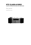
© 2003 Coda Technologies, Inc. ALL RIGHTS RESERVED CD TUNER VIDEO AUX SUBWOOFER MONITOR SELECTOR I N T E G R AT E D A M P L I F I E R UNISON STANDBY N T I N U 20 LEVEL LEVEL STATUS STANDBY LEFT RIGHT SUB ALL LEFT RIGHT SUB ALL LEVEL SELECT LEVEL DOWN LEVEL UP C O N T I N U U M UNISON 3.3 OWNERS MANUAL PRECA UTIONS PRECAUTIONS 1 CAUTION WARNING ! CAUTION CAUTION: TO PREVENT ELECTRIC SHOCK, DO NOT REMOVE COVER. NO USER SER VICEABLE PARTS INSIDE, REFER SERVIC ING TO QUALIFIED SERVICE PERSONNEL. THIS SYMBOL IS TO ALERT YOU OF THE PRESENCE OF UNINSULATED DANGER OUS VOLTAGE WITHIN THE UNIT'S EN CLOSURE THAT MAY BE OF SUFFICIENT MAGNITUDE TO CONSTITUTE A RISK OF ELECTRIC SHOCK. ! THIS SYMBOL IS INTENDED TO ALERT YOU OF THE PRESENCE OF IMPORTANT OPERATING AND MAINTENANCE INSTRUCTIONS IN THE LITERATURE ACCOMPANYING THE UNIT. WARNING WARNING: TO PREVENT FIRE OR SHOCK HAZARD , DO NOT EXPOSE THIS UNIT TO RAIN OR MOISTURE. TO AVOID ELECTRICAL SHOCK , DO NOT OPEN THE UNIT. REFER SERVICING TO QUALIFIED PERSONNEL. CAUTION •Never install or remove the power cord from the chassis unless it has been disconnected from the AC power source first. •Never pull on the power cord when removing it from an AC power source. Grasp it by the plug. •Do not leave the power cord connected to an AC power source unless it is connected to the unit. •It is recommend that during extended periods of nonuse that the units power cord be unpluged from its AC power source. •Route the AC power cord so that it will not be damaged or walked on. CONTENTS 2 PRECAUTIONS.................................................1 PRECAUTIONS.................................................1 INTRODUCTION................................................3 INTRODUCTION................................................3 WARRANTY.......................................................4 WARRANTY.......................................................4 DESCRIPTION...................................................5 DESCRIPTION...................................................5 INSTALLATION..................................................7 INSTALLATION..................................................7 REMOTE CONTROL............................................9 CARE..................................................................10 CARE.................................................................. SPECIFICATIONS..............................................11 ADDENDUM........................................................12 INTR ODUCTION INTRODUCTION 3 Thank you selecting Continuum Electronics. The Unsion Integrated Amplifier is a precision instrument that will provide you with many years of listening enjoyment. Please take a few moments to read this brief manual to insure maximum benefit from your electronic system. WARRANTY 4 LIMITED FIVE YEAR WARRANTY Continuum Electronics extends to the original owner coverage of defects in materials and workmanship for a period of five years from date of purchase. This warranty does not include a) damage in shipment b) damage caused by accidental or in tentional misuse or abuse c) units not registered with Continuum Electronics d) damage resulting from unauthorized modifications or repairs. Liabil ity is limited to the repair or replacement, at our option, of any defective component and shall not include damage due to short circuits, property and or consequential damages which may result from the failure of this product. If this product should ever require servicing, contact: Coda Technologies, Inc 8274 Mediterranean Avenue Sacramento, CA 95826 PHONE: 916.383.3653 FAX: 916.396.8296 www.coda-continuum.com CUSTOMER RECORD MODEL NO.__________________________ SERIAL NO.__________________________ DATE OF PURCHASE_____/_____/_______ DEALER NAME_______________________ DEALER ADDRESS____________________ CITY________________________________ STATE______________________________ ZIP_________________________________ OWNER_____________________________ STREET ADDRESS____________________ CITY________________________________ STATE______________________________ ZIP_________________________________ DESCRIPTION 5 The remote controlled Continuum Electronics Unison Integrated Amplifier is designed with a level of thoroughness reserved only for the finest preamplifier and amplifier gain stages. Analyti cal, design techniques both objective and subjective, are applied in an open-minded fashion with musical perfection as the goal. PREAMPLIFIER SECTION On the faceplate, the straightforward controls and display provide comprehensive functionality to the user. All input selections have LEDs to show when they are in use. Buttons control both volume and balance, with an LED display to show which channels are being adjusted. Settings for the volume and balance are pre cisely indicated in dB of attenuation by the LED display. Gain is provided by the high performance Burr-Brown PGA2310, successor to the highly acclaimed Crystal Semiconductor CS3310. This new digitally controlled analogue device features an improved output buffer and increased voltage swing for high level input signals. Digitally controlled level tracking allows 1 dB per step attenuation without error. The digitally controlled stepped resistors and a zero crossing detection circuit allow for "zipperfree" operation. Total harmonic distortion is less than 0.005% with a signal to noise ratio approaching 130 dB. Unlike other integrated amplifiers, Unison offers true “separates” performance. The preamplifier power supply even has its own independent transformer taps. A reference voltage is developed by delivering constant current to zener diodes. The resulting voltage is heavily filtered and delivered through class-A followers. The non-reactive, low-impedance and extremely wide bandwidth voltage rails yield a perfectly stable power source for the gain stages. DESCRIPTION 6 AMPLIFIER SECTION Differential voltage gain throughout provides exceptional rejection of external noise and contributes to the inherent stability of the circuit. The unit also uses output followers operating without feedback. The front end is designed to provide a slew rate of 50 V/us without entering class B operation as is common in many other designs. This com bined with excellent high frequency design insures linear operation at high speed. The supplies take a very direct approach to high performance. A top quality toroidal transformer capable of 2,000 VA is utilized, and 40,000 uF of total capacitance assure an overbuilt power supply. The current stage is capable of producing peak current outputs in excess of 50 peak Amperes with a degree of linearity and speed which is not matched by other designs when producing only a fraction of this current. This is achieved by the implementation of several distinct circuit fea tures. Each channel uses 18 individual output transis tors with a combined power rating of 3,600 Watts and 75 Amperes and a bandwidth of 10 MHz. The Unison 3.3 operates in Class A up to approx imately 7 Watts. At higher output levels, the amplifier slides into Class AB operation. The bias section is designed to produce a precision trans ition with no abrupt changes in distortion or output impedance. This "Precision Bias" technique yields seamless performance regardless of the complexity of the load impedance. With such linearity and bandwidth no overall feedback correction is used. One advantage of this is a high degree of immunity from interactions with complex speaker loads or cables. The AC power entry module has a line fuse, a spare fuse and a power switch. Since the power draw is low, the preamp may be left on, except when installing, changing cables, or changing system components. INST ALLA TION INSTALLA ALLATION 7 ALLA T INSTALLA ALLAT 8NST INST 7 LOCA TION LOCATION To provide for adequate ventilation you should allow at least six inches of unobstructed space above and a couple of inches on each side of the amplifier. Because of its large power supply, a local magnetic field may be picked up by CD players, turntables and the like. For this reason you should provide at least a foot of space between the Unison and these components. Be certain the Unison and all associated equip ment is turned off before making any connec tions. THIS PRODUCT IS DESIGNED, ENGINEERED AND BUILT IN THE UNITED STATES OF AMERICA. LEFT SPEAKER OUTPUTS RIGHT 5 5 5 5 FUSE TYPE SLOW BLOW SLOW BLOW SLOW BLOW SLOW BLOW AMP AMP AMP AMP V O LTA G E 100V 120V 220V 240V ON FUSE / VOLTAGE SELECTOR MAIN POWER 120 OFF F G ! FOR CONTINUED PROTECTION AGAINST SHOCK OR FIRE HAZARD, REPLACE FUSE WITH SAME TYPE AND RATING, DO NOT EXPOSE THIS UNIT TO RAIN OR MOISTURE TO PREVENT ELECTRIC SHOCK, DO NOT REMOVE COVER. NO USER SERVICEABLE PA R T S I N S I D E . R E F E R S E R V I C I N G T O QUALIFIED SERVICE PERSONNEL. CAUTION WA R N I N G RIGHT SPEAKER OUTPUTS RIGHT A. SELECTOR INPUTS Signal inputs for CD, Tuner, Video, Aux. B. MONITOR Signal inputs and outputs for a tape deck or other recording device. ~ AC LINE INPUT PRODUCT IDENTIFICATION RIGHT LINE LEVEL RIGHT LOW LEVEL LEFT LOW LEVEL LINE LEVEL LEFT LEFT MAIN OUTPUTS D SUBWOOFER PREAMP C9 RIGHT LEFT IN MONITOR OUT B E 15 15 8 8 AC LINE FUSE CHART TUNER VIDEO AUX A SELECTOR x x x x 20mm 20mm 20mm 20mm CD LEFT REAR PANEL CONNECTIONS E C. PREAMPLIFIER OUTPUTS Signal outputs for an optional outboard amplifier. D. SUBWOOFER OUTPUTS Variable outputs for a powered subwoofer which track the master volume. E. AMPLIFIER OUTPUTS Signal output to your speakers is made through heavy-duty gold-plated five-way binding posts. Be sure of correct speaker phasing by matching the (+) on the amplifier to the (+) on the speaker and the (-) on the amplifier to the (-) on the speaker. F. POWER SWITCH The rear-mounted power switch on the Unison is intended only for initial powering of the unit and for complete shutdown for connecting cables. The rocker switch must be in the "ON" position for the Unison to power up and should only be turned off when the Unison has been in Standby Mode for at least 1 minute. G. AC LINE INPUT Insert the power cord into the AC receptacle and then connect to an appropriate power source. The fuse can be removed by pulling the fuse drawer out and clipping in a new one. Once all connections are made the power switch may be set to the on position. The Unison may be left on as it draws a negligible amount of power. INST ALLA TION INSTALLA ALLATION 8 FRONT PANEL CONNECTIONS A. LEVEL A digital volume control adjusts the level. One button increases the volume; the other decreases the volume. LEVEL SELECT C. LED DISPLAY The volume setting for each channel is indicated by this decibel (dB) display. The display ranges from maximum output, indicated by a display of 99, to a maximum attenuation, indicated by 00. B LEDs in the display window indicate STANDBY MODE (yellow pinpoint LED) and the CHANNEL mode currently selected. The LED to the left of the volume digits indicates that ALL channels are being controlled the VOLUME control. MONITOR A M P L I F I E R UNISON I N T E G R AT E D STANDBY SUBWOOFER N T I N U 20 LEVEL STANDBY LEFT RIGHT SUB ALL CD TUNER VIDEO AUX SELECTOR C LEVEL STATUS LEFT RIGHT SUB ALL A LEVEL DOWN LEVEL UP B. CHANNEL LEVEL / BALANCE SELECT Relative inter-channel balance is adjusted bu using the Level Select button to choose right, left, sub, or all channels. D E F G The colored arrow LEDs indicate which channel is being adjusted. The arrows also serve as a reminder to continue advancing the channel select to the right until the round LED next to the volume display is illuminated. This indicates that the VOLUME function has returned to controlling ALL channel simultaneously. D. STANDBY Switches the amplifier section of the Unison on and off. In STANDBY, the preamplifier is still operational, thus, it may be used to drive an additional external power amplifier. NOTE: The Unison must be placed in STANDBY mode for at least 1 minute before turning the rear main power switch off. E. SUBWOOFER Switches the subwoofer output signal on and off. F. MONITOR For monitoring the output of a recording device (tape deck, mini disc, DAT deck, etc.). G. SELECTOR Selects the stereo input: CD, Tuner, Video, and Auxilary. 9 REMOTE CONTROL 9 The Unison may be operated by remote control. To operate, set the remote to AUD. The optional URC universal learning remote includes access to advanced functions of the Unison and can also be used to control many other audio and video components. For instructions on the remotes other capabilities, refer to the separate universal remote manual. 1. REMOTE FUNCTION SELECTOR [AUD] This series of 8 buttons are used to select an audio component to control. To control the Unison, press the [AUD] Button. 1 2 AUD CD DVD AUX SAT TV VCR CBL POWER 4 VOL 3 2. AMPLIFIER POWER / STANDBY [POWER] MUTE CH 5 T/V GUIDE MENU 3. [MUTE] This button completely mutes the left and right channels, which is indicated by the flashing display on the Unison. To unmute you must press the mute button again. Note: while muted you can still change the volume level. 4. VOLUME ADJUST [VOL] PAUSE R E W PLAY STOP PRE. CH EXIT 1 5. INPUT SEQUENTIAL SELECT [CH] These up and down buttons select the source which will be presented to the inputs. Individual inputs are sequentially selected by pressing these up/down buttons until desired input is reached. F . F SEL 2 3 FAV SLEEP 4 5 6 INFO 0 PRO.L 7 8 9 +10 0 ENTER NEXT ALT SHIFT TEST 3.CH PIP TUNER VIDEO AUX MON PROC CHANNEL 7 M1 8 M2 9 M3 7. MONITOR LOOP [MON] This button switches in the playback ouput of recording device(tape deck, mini disk, ect.). Tape record outputs are fixed to the input selected. 8. PROCESSOR / SUBWOOFER [PROC] Depending on how your Unison is configured, this button either turns the subwoofer output on/off or activates an optional signal processor loop. 6 CD 6. INPUT DIRECT SELECT [CD] [TUNER] [VIDEO][ AUX] This feature, only accessable from the enhanced URC remote, allows direct button access to individual inputs. M4 LIGHT HOME THEATER MASTER LEARNING REMOTE CONTROL 9. CHANNEL LEVEL / BALANCE [CHANNEL] Relative inter-channel balance is adjusted by selecting the right, left, sub, or all channels. The selected channel iis indicated by the LEDs in the to the left of the volume display digits 0. DISPLAY MODE SELECT [INFO] An enhanced feature only available from the URC remote on Unisons with software rev.12 and later. Turns off all LED indicators EXCEPT standby and the volume digits. Returns to full Display Mode by pressing [INFO] again or any function other than volume, mute, or standby. CARE 10 If you wish to clean your amplifier use a diluted ammonia based cleaner. Do not use any abrasive cleaners or chemical solvents. Take care not to damage the aluminum faceplate, since aluminum is a medium hardness metal and can be scratched by the careless use of tools during installation. The amplifier may overheat and the finish may fade if exposed to direct sunlight or intense heat sources for prolonged periods. Save your box and packing material, they may be necessary for moving or shipping the unit for servicing by the factory. SPECIFICA TIONS SPECIFICATIONS 11 RATED POWER 300 Watts/channel, 20Hz to 20kHz, both chan nels driven into 8 Ohms 600 Watts/channel, 20Hz to 20kHz, both chan nels driven into 4 Ohms Class A Operation up to 7 Watts, sliding to Class AB at higher output levels BANDWIDTH -3dB at 5 Hz through 100kHz DISTORTION Less than .05% from 10Hz to 20kHz at 300 Watts both channels driven into 2 through 8 Ohms GAIN 26dB CURRENT CAPABILITY 50 Amperes peak per channel SLEW RATE 50 Volts/microsecound INPUT IMPEDANCE 20k Ohms OUTPUT IMPEDANCE .08 Ohms from 20Hz to 20kHz DAMPING FACTOR Greater than 100 NOISE More than 100dB referenced to rated output POWER SUPPLY 2,000VA toridal transformer with independant rec tifiers and 40,000 uF of capacitance DIMENSIONS Faceplate: 17 inches wide by 5.5 inches tall Chassis: 16.75 inches wide by 6 inches tall by 14 inches deep WEIGHT 55 lbs ADDENDUM CARE 12 10 The Unison Series 3 Integrated Amplifer represents an evolutionary design effort and includes several refinements and enhancements, based upon input from our engineering staff, prominent audio critics,and owners of previous versions of the Unison. Recent changes include: The Burr-Brown PGA2310 replaces the Crystal CS3310 Digitally Controlled Anologue Attenuator Preamp stage supply voltage raised to provide immunity from input overload. Input overload level raised to 10 Volts. Vishay resistors used in preamp signal path All IC sockets now Samtec w/gold pins Volume Display Count reversed to 0-99 URC9000 Learning Remote Option provides additional functionality LED Display Modes for partial visual muting of display Improved Standby Power Switching eliminates turn-on thump. Unison 3.1 raised to 125W into 8 Ohms "Signature Mods" introduced, including options for upgraded audiophile connectorization, internal wiring, specialty solder, and custom finish and chassis elements. Some of these options include: Cardas®, WBT®, and Cliff® Binding Posts Cardas® and Vampire® OFC RCA Connectors Cardas® and Jena Labs® Chassis Wiring Cardas® and WBT® Audiophile Solder Special Gold and Silver Finishes Custom chassis components. For more information, visit our website at www.coda-continuum.com ALL TRADEMARKS CONTAINED HEREIN ARE THE PROPERTY OF THEIR RESPECTIVE OWNERS.