1
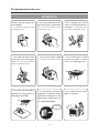
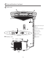
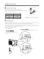
MUND CLIMA
®
CORNER SPLIT
COOL ONLY:
MUR-12 C
HEAT PUMP:
MUR-12 H
User's manual
The instructions before use
WARNING
Ensure the power plug is Inserted tightly
or it will cause electric shock
overheating or fire.
Never turn off the power sup-
Never damage the power
ply in the process of operation
cable or use the non-particu-
or it will cause electric shock
lar kinds. or it will cause elec-
overheating or fire.
tric shock overheating or fire.
Never share the same socket
Never operate with wet hand
Never make firgers or stock
with other electrical appli-
or it will cause electric shock.
into the air intake or outlet
ances. or it will cause electric
vents, or it will bring harm.
shock overheating or fire.
Never blow the cold wind to
If something unnormal
the body for a long time or it
happaned (burning smell)
will damge the health.
Please turn off the power soon
then contact with service center of MUNDOCLIMA.
Turn off Power
-- 1 --
Never repair the air conditioner by yourself.
Don’t use fuse with differ-
Never climb air conditioner
ent capacity.
Turn off the power supply
when cleaning the air
use iron to replace fuse will
conditioner,otherwise,it’ll
cause malfunction or fire.
cause electric shock or do harm
to you.
Wire
Never pull out the power plug
Never let the air conditioner
Chemical Spray should be
by pulling the power cable. Oth-
to blow to the heater, Other-
placed be one meter away
erwise, it will lead to fire caused
wise, it’ll cause non-completely
from the units or it will cause
by overheating of electrical wire.
burning lead to carbon-monoxide
fire or explosion.
poisoning.
Keep an eye on the chassis
of outside unit is damage or
Don’t step on the top of the
outdoor units.
Don’t block the air intake
or outlet vents of indoor units
and outdoor units.
not. If ignore the damage,
This will decrease the effi-
units may be fall down and do
ciency or even break down
harm to people.
-- 2 --
Name and funciton of each part
Indoor unit
Big/small air intake grill
louver
liquid crystral displayer
Power plug
drainage hose
front grille
remote controller
Outdoor unit
big handle
Air in
Air in
-- 3 --
Remote control operation procedure
Name and Function-Remote control
Note:
Be sure that there are no obstructions between reciever and remote controller.
Don’t drop or throw the remote control.
Don’t let any liquid in the remote controller and put the remote controller
directly under the sunlight or any place where is very hot.
FAN button
Presse this button to
change the fan speed of:
SWING button
When it is pressed, the
louvers start to rotate
automatically and stop
when repressed.
AUTO FAN
TEMP. button
SET TEMP. increases 1oC
by pressing button once,
and decreases 1oC by pressing button once.
At COOL mode operation,
SET TEMP. can be selected
from 16oC to 30oC.
At DRY mode operation,
SET TEMP. can be selected
from 16oC to 30oC
At HEAT mode operation,
SET TEMP. can be selected
from 16oC to 30oC.
COOL mode
DRY mode
FAN mode
HEAT mode
1/0 button
Press this button to turn
on or turn off the unit.
MODE button
Press this button to
change the operation
mode in order of
1/0
AUTO
-- 4 --
Name and Function-Remote control .(Remove the cover)
Note:
This type of remote controller is a kind of new current controller. some
buttons of the controller which are not available to this Air conditioner
will not be described below.
Operate on unmentioned buttons would not impact on the normal use.
Liquid crystal displayer
It shows all set contents.
SLEEP button
Press this button to set
SLEEP operation. and
stop when repressed
TIMER OFF button
At operating, press TIMER
OFF button, set OFF
TIME in range of 0 to 24
hour to stop the unit automatically.
1/0
0
24h
Timer
cancellation
TIMER ON button
At stopping, press TIME ON button, set ON TIME in range of 0 to
24 hour at the interral of 0.5h to
start the unit automatically.
0 24h
Timer
cancellation
-- 5 --
COOL mode operation procedure
According to difference between room temp., and set temp. microcomputer can control
cooling on or not.
If room temp. is higher than set temp. , compressor runs at COOL mode.
If room temp. is lower than set temp., compressor stops and only indoor fan motor runs.
SET TEMP. should be in range of 16oC to 30oC.
4. Press FAN button, set fan
speed.
3. Press SWING button, the
louvers start to rotate automatically, and stop when
repress.
5. Press TEMP. button, set
suitable SET TEMP.
2. Press MODE button, set
1/0
operation mode.
1. Plug in, press 1/0 button, then
air conditioner is turned on.
-- 6 --
HEAT mode operation procedure
If room temp. is lower than set temp. , compressor runs at HEAT mode.
If room temp. is higher than set temp., compressor and outdoor fan motor stop, only indoor
fan motor runs a while and stop.
SET TEMP. should be in range of 16oC to 30oC.
3.Press SWING button, the
louvers start to rotate automatically, and stop when repress it.
4.Press FAN button, set fan
speed.
5.Press TEMP. button, set
suitable SET TEMP.
1.Plug in, press 1/0 button,
then air conditioner is turned
on.
1/0
2.Press MODE button, set
operation mode.
When the unit (cool only) recieved the control signal which is used under the heat mode,
it will operate according to the fan mode.
-- 7 --
DRY mode operation procedure
If room temp. is lower than set temp. much more, compressor outdoor and indoor fan
motor stop. If room temp. is between 2oC of set temp., Air conditioner is drying. If
room temp. is higher than set temp., it’s at COOL mode.
SET TEMP. should be in range of 16oC to 30oC.
3. Press SWING button, the
louvers start to rotate automatically, and stop
when repress it.
4. Press TEMP. button, set
suitable SET TEMP.
1/0
2. Press MODE button, set
operation mode.
FAN speed couldn’t be
changed after the “
”
being set.
1. Plug in, press 1/0 button,
then air conditioner is
turned on.
-- 8 --
AUTO mode operation procedure
Under Auto mode operation, standard SET TEMP. is 25oC for COOL mode and 20oC for
HEAT mode .
1/0
1. Plug in, Press 1/0 button, then
air conditioner is turned on.
2. Press MODE button, set AUTO
operation mode.According to
room temp., microcomputer can
automatically set
operation mode, so as for best effect.
-- 9 --
TIMER mode operation procedure
TIMER ON button
At stopping, press TIME
ON button, set ON TIME
in range of 0 to 24 hour to
start the unit automatially.
0 24h
1/0
cancel TIMER
TIMER OFF button.
At operating, press TIME OFF
button. set OFF TIME in range
of 0 to 24 hour to stop the unit
automatically.
0
24h
cancel TIMER
-- 10 --
SLEEP mode operation procedure
As the unit is cooling or drying, if SLEEP operation is set, SET TEMP. would
increase 1oC in 1 hour and 2oC in 2 hours.
As the unit is heating, if SLEEP operation is set, SET TEMP. would decrease
1oC in 1 hour and 2oC in 2 hours.
4. Press FAN button, set fan
speed.
3. Press SWING button,
the louvers start to rotate
automatically, and stop
when repress.
6. SLEEP button
Press it to set SLEEP operation.
5. Press TEMP. button, set
suitable SET TEMP.
2. Press MODE button, set
or operation
mode.
1/0
1. Plug in, Press ON/OFF
button,then air conditioner is
turned on.
-- 11 --
How to insert batteries
1. Remove the cover from the
back of the remote control.
2. Insert the two batteries (Two
AAA dry - cell batteries)
and press button “ACL”.
3. Re - attach the cover.
NOTE:
Don’t confuse the new
and worn or different
batteries.
Remove batteries
when not in use for a
long time.
2 Insert the 7# batteries
1 Remove the cover.
3 Re - attach the cover.
-- 12 --
The optimum usage
In order to save electricity,use it Conveniently and safely
Set an appropriate room
temparatrue,overcold is
harmful to health
Be sure to turn off the
power socket when
do not use in a long
time.
Clean the air filter and
change a new one or
apply to sunlight
reqularly.
Please take out the
batteries when do
not use in a long time.
Avoid direct sunright,
and leakage of cold air.
Earth wire
Earth wire should be connected with specific equipment of constructures, if not, please turn to
the professionals for instruction. The socket must connect to the earth reliable and it has
enough capacity leakage breaker and air switch (16A), Don’t connect the earth wire to gas or
water pipes, lightening rods or telephone earth wire.
-- 13 --
USER NOTICES
Select the most appropriate temperature. It
can avoid the electricity wasting.
The airflow direction can be adjusted appropriately. The louvers can be adjusted downward
at heating operation, and upward at cooling operation.
Don’t leave windows and doors open while the
air conditioner is on for a longtime. It can
decrease the air conditioning capacity.
Don’t blow the wind to animals and plants
directly. It can cause a bad influence to them.
Splashing water on the air conditioner can
cause an electric shock and mal - function.
The ground must be connected.
Don’t connect the earth wire to gas or water
pipes. lighting rods or telephone earth lines.
Air conditioner should be operated with stable
voltage in range of 198 -- 242V 1ph. otherwise, compressor would vibrate terribly to
damage refrigeration system.
Don’t use the air conditioner for other purposes, such as drying clothes, preserving
foods, etc.
-- 14 --
Care and Maintance
Replacement of Air cleaner
fastener of
leftside grill
faster of rightside grill
button
Central front panel
hook
(to avoid falling
down of the grill)
small air intake grill (rear)
big air intake grill (front)
1 Remove the air intake grill
Remove the big air intake grill
(front)
Remove the small air intake grill
(rear)
Stop the units, and turn off the power plug, Press
it as following, drawing the grill outside then it
can slip from the body.
Draw it along horizontal and slighthy downward.
Take down the hook enable to clean.
Press the button,then the big air intake grill can be
taken down from the body.
button
Take down the hook of big air intake grill
enable to clean it.
Notices:
Don’t let grill hit with wall and other things to
avoid surface damage.
-- 15 --
2 Clean the air intake grill.
Notices:
Don’t clean the surface with brush to avoid the damage of surface.
If the grill is too dirty, you can wash it with mild detergent.
Don’t dry it under direct sunlight or heater, or it will cause decoloration and deformation of grill.
3 Assemble air intake grill (hook is used to avoid falling down of grill, so it is necessary)
Assemble the small air intake grill
(rear)
Assemble big air intake grill
Hang the hooks on the piping hole of small air
intake grill.
Hang the hooks on the piping hole of big air intake
grill,placing the leftside hole of leftside grill into
the left fastener.
Place small air intake grill facing central panel
Installation groove, inseting slightly downward
and horizontlly.
Press the fastener of rightside body as following,
facing the fastener. then unclinching the button.so
as to let fastener insert into the hole.
hook
central panel
button
Raise the big air intake grill slightlhy, then push the
body horizontally.
-- 16 --
Attention
Stop operation and turn off the power,or the
high-speed moter may cause damage to
people.
It doesn’t need too much strength,making this
manual as reference,or it will damage to internal parts.
Cleaning the air filter
1
Stop operation and turn off
the power plug.
2
Disassemble the front big air intake grill
Pressing the location as following,draw the
big airintake grill,making it fall down of the
body.
3
Disassemble the air filter
Press two buttons,then slightly upward
after discharge from the hole, stretch
forward the air filter.
Button
4
Clean the air-filter
To clean the dust adhering to
the filter,you can either use a
cleaner,or wash them with water.
5
Assemble the air filter
fix into the air filter along the direction groore.
6
Hole
Placing two buttons into the hole.
Button
Hole
Direction
groove
7
Assemble the big air intake grill
Drag the grill horizontally then push into the
body.
8
Turn on the power plug
Notices:
1. The blockage of filter may decrease the efficiency of cooling and heat further more it will increase the electric charge by 5-10%.
2. Make sure not damage the filter of the grill, while cleaning it, Otherwise it will have an impact on filtrarion. If damaged, please
purchase from the local dealer.
-- 17 --
Installation and rechange of air cleaner
The air cleaner combined with a low-temperature asepsis accelerant (white-green) and an active carbon(black).
The former can deodorize and kill the bacillus of the air. The latter can adsorb the atom of air, enhancing the quality
of air in the room.
If the air-cleaner is dirty, you can wash it with water and dry it by nature. Normally clean it once half a year.
If Air-cleaner use for a longtime, the efficiency will be decreased. Normally it should be changed per three years.
1
Disassemble the big air-intake grill.
Stop operation and turn off the power plug.As
following,draw the grill outside then it will fall down
from the body.
2
Disansembk the air filter
Hold two buttons then press it slightly upward.After it
disassemble from the hole, then draw it forward.
Hole
3
5
Disassenble the air-cleaner
Hold the handles of air cleaner,then pull it along the
direction groove.
4
rechange the air-conditioner
Press the button then the upper cover will loosen.Take
out the air-cleaner you have the option to change a new
one or clean the old one.
assemble the air-cleaner.
Insert the air cleaner into groove of fixer.
6
Assemble the air-filter
Insert the air-filter into the groove direction groove.
groove
groove
rail
7
Put two button of air filter into the piping hole.
8
Button
-- 18 --
Assemble big air intake grill.
Draw the air intake grill horizontally then push it into
the body.
Troubleshooting
Check the following points before requesting on service center of MUNDOCLIMA if the
malfunction persist, it saves your time and money.
Phenomenon
Please
waiting
Trouble Shooting
Indoor unit does not
operate immediately
when the air conditioner is restarted.
Once the air conditioner is stopped, it will not operate in approximately 3 minutes to protect itself.
There’s unusual
smell blowing from
the outlet after operation is started.
This is caused by the odors in the room which have
been breathed into the air conditioner.
Sound of water
flow can be heard
during operation.
This is caused by the refrigerant flowing inside the
unit.
Mist is emitted during cooling operation.
Because the air of the room is cooled down rapidly
by the cold wind and it looks like the fog.
Creaking noise can
be heard when start
or stop the unit.
This is caused by the deformation of plastic due to
the change of temperature.
Air conditioner does
not operate
at all.
Has the power been shut down?
Is the wiring loose?
Is the leakage protection switch in operation?
Is voltage higher than 242V or lower than 198V?
Is TIMER ON in operation?
shut off
Cooling (Heating)
efficiency is not
good.
Is SET TEMP. suitable?
Is air inlet or outlet obstructed?
Are air filters dirty?
Is indoor fan speed set at low speed?
Is there any other heat sourse in your room?
Wireless remote
controller is not
available.
Is the remote control unit out of effective distance
to the indoor unit?
Replace the worn batteries of wireless remote controller.
Are there any obstructions between the wireless
remote controller and the signal receptor?
-- 19 --
Immediately stop all operations and plug out, contact with service center of in following
situations.
Unusual noise can be heard during operation.
Power fuse or switch often breaks.
Carelessly splash water or something into air conditioner.
Electrical lines and power plug are very hot.
Wind blowing from the outlet smells terrible during operation.
-- 20 --
Technical parameter
MODEL
MUR-12C
MUR-12H
Function
Cooling
Heat pump type
Assistant function
collocated with air-cleaner
Cooling capacity (W)
3500
3500
Heating capacity (W)
–
4000
Rated voltage
~220V
Rated frequency
50Hz
Rated current (A)
5.9/–
6.0/6.25
Maximum input current (A)
6.9
7.0
Rated power (W)
1280/–
1300/1320
Maximum input power (W)
1480
1500
480
3
Air circulation (m /h)
Refrigerant and its weight (Kg)
Water proof level
R22 0.85
R22 1.20
IP20 (Indoor)
IP24 (Outdoor)
Noise (Inside/Outdoor) dB(A)
41/57
Climate type
T1
Protection of electrical shock
I
Quality (Kg)
15/32
Size (cm)
Indoor 23.0 x 72.5 x 72.5 (Width x radius x Depth)
Outdoor 88.8 x 54.0 x 32.0 (Width x high x Depth)
* The aforementioned parameter strictly striocthy accort to GB/T7725-1996. lts cooling/heating capacity are
examined before ex-factory.
* If there is change in the parameters, Please consult the paremeter on the nameplate.
* You can examine the biggest input power under biggest cooling/heating coditioner.
– 21 –
Accessories and Installation diagram
Accessories (Check that all accessory parts are present before installation)
No.
Part name
Diagram
Qty
Specification
Memo
1
Wall-mounting frame
2
2
Wireless remote contrller
1
3
Battery
2
4
Power connection cable
1
5
Signal control cable
1
6
Wall-mounting frame
1
7
Tapping screw
10
ST4.2X25
Fix the rear panel
8
Drain hose
1
L=2m
Packaged with
connection piping
9
Gum type sealer
1
10
Piping-hole sleeve
1
11
Bind strip
12
Connection pipe
13
Thermal insulation hose
1
14
Big connection frame
1
15
Small connection frame
1
16
Small air intake grill
1
17
Big air intake grill
1
18
Air-cleaner
1
7 1.5V
Heat pump type only
Packaged with
connection piping
Packaged with
connection piping
Packaged with
O6/O9.5(12 )
connection piping
O35X500
* Be sure to use the accessories allessordes and parts, or it will cause leakage, electric shock or fire.
* Except the appointed accessories, the rest should be placed in the package carton of indoor unit.
-- 22 --
Installation dimension diagram
Important Notice
1. The unit should be installed by professionals under the quidance of this manual,
ensuring the normal use of it.
2. Please contact with local service center before installation, the malfunction in
the process of it. caused by no specific center may be diffiaut to deal with.
3. Remove the unit should under the guidance of the professionals.
-- 23 --
Location of installation
Indoor unit
1. The inlet and outlet should not be covered so that the outflow air can reach all parts of the room.
2. Install in a location where it is easy to connect to the outdoor unit.
3. A location from which the condensation water can be drained out conveniently.
4. Avoid a location where there is heat source, high humidity or inflammable gas.
5. Install in a location where it is strong enough to withstand the full weight and vibration of the unit.
6. Be sure that the installation conforms to the installation dimension diagram.
7. Be sure to leave enough space to allow access for routine maintenance.
8. Install in a location where is 1m or more away from other electric appliances such as television, audio
device, etc.
9. Select location where it is easy to remove and clean the filter.
10. Be sure that the distance from the location to the ground is more than 2.3m.
Outdoor unit
1. Select location from which noise and outflow air emitted by unit will not disturb neighbors.
2. Select location where ventilate freety.
3. The inlet and outlet should not be covered.
4. The location should be able to withstand the full weight and vibration of the outdoor unit.
5. There should be no danger of flammable gas or corrosive gas leaks.
6. Be sure that the installation conforms to the installation dimension diagram.
NOTE:
Install in the following place may cause mal-function. If it is unavoidable, contact with service center of
MUNDOCLIMA please.
Place where oil (machine oil) is used.
The place where a lot of salinities such as coast exists.
Place where a sulfured gas such as the hot spring zones is generated.
Place where high-frequency waves are generated by radio equipment, welders and medical equipment.
Other place with special circumstance.
-- 24 --
Install the indoor unit
Install the rear panel
(unit:mm)
Upper wall mounting frame
Ripht wall mounting frame
R72
5
Left wall mounting frame
Outlet of indoor unit
Rightside wallmounting frame
Leftside wallmounting frame
Space to certring
Space to ceiling
Outlet of
Outlet of
indoor unit
indoor unit
Space to wall
Piping hoel
Piping hoel
The installation of wall mainting frame
1. Install the wall mountly frame in turn, then use gradienter to test whther they are horizontal or not.
2. After installation, pulling to ensure it is stable.normally the wall mounting frame can sustain the weight of an aduct (60kg)
Upper wall mounting frame
Wall frame fixed screw
Gr
adi
ent
ad
Gr
er
ien
ter
Upper wall
frame fixed screw
Rightside wallmounting frame
Leftside wallmounting frame
fixed parts of indoor unit.
fixed parts of indoor unit.
Space for corner
Space for corner
Connect with the hooks of big air intake grill
-- 25 --
Installation of piping
1. After installation of the wall mounting frame, to locate a declining pipeing hole.
2. Choose the suitable way for piping and stretch the pipe and wire.
3. Ensure to fix a piping-hole sleeve in order to protect piping and cable escape from damage while go
through the wall.
Installation of right piping(rear)
Installation of left piping(rear)
Connection pipe
(Singal wire)
tubing
drain hose
Assemble of upper tube
Assemble of downside tube.
connection wire (including singal wire)
connection wire (including singal wire)
tubing
tubing
drainage hose
-- 26 --
drainage hose
The installation of indoor unit
1.first take off the air filter and the upper cover of electrical box before installation.
2.Hold the big handle then place indoor units on the hook of wall mountaing frame.
Notice:
Avoid the damage caused by the air conditioner collapse into the wall.
Don’t clamp the louver
3.Move the air-conditioner in all directions, ensure they are held tightly.
4.Fix the two position with screw as picture B shows.
5.The installation height of indoor unit must be more than 2 meters high.
Filter
Air outlet grill
Louver
Hook
Hook
Big handle
Screw(ST4.2
Fig. A
25)
Fig. B
Installation of drain hose
Heave
1.Be sure the drainage hose must be placed slightly down
Bent
for the sake of convenient drainage.
2.Don’t place it with heave,swirl and don’t intrude into
into water.
3.You should use heat insulation material when connect
long drain hose.
Don’t intrude
into water
4.The drainage panel has two waterspout,you can chose which one to drain the water according to actual
installation.If the location is different, you can exchange the installation of drainage pipe and blockage.
Installation of drain hose
Connect the connection pipe and two outlet pipe of indoor unit, fastening the terminal nut of the former.
Notice
Connect the connection pipe with the indoor unit firstly and the outdoor unit secondly.
Be careful in bending the connection pipes, or you will damage the pipes.
If the tightening torque is too much in tiphtening in the flame nuts, leakage will happen
Wrap the connection place by specific heat freservation.
-- 27 --
Electric connection
1. Take down the upper corer and wring cover of electrical box.
2. For KF(R)-28GJW/A300 KF(R)-35GJW/A300,KF(R)-40GJW/A300, first connect the blue wire of the power
connection cable to the terminal “N(1)”, the brown one to “2”,the red one to 3(for KF(R)-40GJW/A300), the
yellow-green one (earthing wire) connect to “
”, as shown in figture A and Figture b.
3.Reassemble the wiring cable and upper cover of electrical box, wiring the wiring clamp to clasp the connection wire. There should be some space between the wire.
Signal control
wire
wiring terminal board
connection
installation
wire clamp
power cable
connection
screw
power connection cable
upper corer of
electrical box
installation corer
of electrical box
wire clamp
(Use only for heat
pump type)
fixed screw
Fig. A
Fig. B
Fig. C
Noices:
All the electrical work must be done by qualified personnel according to be local rules and this manual.
The rated votlage and exclusive the unit must be used.
Be sure to install leakage circuit breaker.
Please choose the specified fuse.
The diameter of power cable should be large enough, use the exclusive wire to replace the damaged wire.
Wiring work should confirm to the national standard.
-- 28 --
hole
The installation of grill frame
1.Insert the hook of leftside grill into piping
hole of indoor unit and hook of wall mounting frame.then fixed it with screws.
2.Insert the hook of right framework of grill
hook
and hole of indoor units, then fix it with screw
* To installation of below pipe, fix use pincers or cutter to open holes in the obligation
groove, then level off the cut with knife and
fix a protection pipe for drain hose.
leftward francwork
grill
rightward frame
work grill
cut-off tailing hole
grill fastener
air filter
Installation of grill
1.Hang the hook rope of left framework of grill
to the hole of rightward grill.
2.Insert the right grill sliphtly into the central
hole of leftward framework of grill. then
horizontally and press it.
3.Install the air filter.
4.Insert the hook of indoor units into the hole of
front grill.
5.Insert left hole of front grill into axial of left
button
hook
grill frame.
Grill fastener
avoid falling
down of grill
Left grill frame
Big air intake
grill (front)
hole
ripnt grill frame
Hook
Central hole
avoid the grill
falling down
Small air intake grill (behind)
-- 29 --
Install the outdoor unit
Torqne wrench
Installation of connect pipe
1.Align the center of piping with the correspond valve.
2.Screw in the plane nut by hand and then tighten the nut with spanner
Spanner
and torgue wrench refer as follows.
Tightening torque(N.m)
Hexangular nut
6
15~20
9.5
31~35
12
50~55
tie in
plane nut
Warning: Biggish torque can destroied nut
Connection of cable
1.remove the big handle.
2.Remove the wire clamp and connect the end of the power connection cable with screws to the wiring
torminal board. Be sure that the wiring connection is in accordance with the indoor units.
3.Fix the power connection cable and singal cable then connect the corresponding connectoor. After clamping
the wire clamp ensure there is some space between wires.
4.Ensure the wire has been clamped.
5. Install the big handle.
Electric connection wiring of outdoor unit, as shown in Fig.B
Elecctric connection wiring of outdoor unit, as
shown in Fig.A
Fig. A
(only use heat pump type)
Fig. B
Big handle
(only use heat pump type)
-- 30 --
The diagrams of unit wiring
Power conncction cable
Power conncction cable
Singal cable
The diagrams of unit wiring
Power conncction cable
Power conncction cable
Singal cable
Notice:
Some mistakes in wiring will cause malfunction of some electrical parts.
After the installation of cable, ensuring there is space between connection place and fixed place.
-- 31 --
Leakage test
screndriver
1. Take down the nut cover of turn off valve in the outdoor unit.
2. Face the central of tubing, tightering the pyramiclal nut with hand.
3. Tighten the pyramidal nut with spanner.
4. Take down the unilateralism nut of liquid ralve and gas valve.
5. Loose the core of liquid valve and check valve by hexangular
panner and screwobiver respectively, discharging some gas from the
latter.
6.After fifteen seconds of discharging, the refrigerant gas appears.
Then close the check valve and tighten the bonnet.
7. Open the core of liquid valve and gas valve entirely.
8. Tighten the bonnet, using suds or leak detector to test whather
leakage happens in the pontes of outdoor unit and pipeline.
(unilateralism valve)
gas pipe
liquid pipe
check valve
gas valve
lighid valve
Fig. 7
9. If condition permits, excluding the air from check valve by vacuum
pump.
Vacuum gauge
bonnet
Vacuum pump
Fig. 8
Let the condension water of outdoor unit.
(only heat pump type)
In heating mode, the condensation water and defrosting
water of outdoor unit can be discharged through drainage
pipe.
The may of installation: clip the tie-in of discharge pipe
into the
25 hole of chassis, then connect the drainage
pipe with the outfall to enable the condensation water and
defrosting water to dischange properly.
Chassis of outdoor unit.
Drainage fie-in of outside
Fig. 9
-- 32 --
Test and Check
Trial-operation
1. Peparation for trial-operation.
(1) Don’t turn off the power before completion of all installation
work.
(2) The control circuitny must be conect correctly tiphtening all the
electrical wire.
(3) The cut-off valve of big or small pipe should loosen.
(4) All the oddments especially the regulus and thrum should be cleared away
from the unit.
(5) Open the upper cover of panel and controller box, enswring the switch is
npper cover of controller box
in the “RUN” mode.
2. May of trial operation.
(1) Turn on the power plug, Pressing the on/off button to begin trial-operation.
(2) Press the button of mode, choosing
to inspect whather it perodate normally.
(3) Operate an emergency.
In the case of lossing the remote controller, you can operate it like following:
(1) In the mode of stop, pressing the switch on the “automatic”, then the unit runs atomatically. The micro-computer choose
according to the room temperature. If you want to stop the unit, pressing the botton on “stop”
(2) In the mode of operation, the unit will stop when the switch is placed on the “stop”.
Notice: “Test” is only trial-operation. under this instance, the unit forcibly operate without hestricted
by temperature. Don’t touch it by normal operation.
Test item after installation
Item and to be tested
The phenomena may happen in the
case of installation impriperly
Is it installed reliably?
The unit may falldown, shaking or nosing.
Has leakage test or not?
Cause not enough cooling (heating) capacity
Is it enough heat insulation?
May cause condensation water
Is it drain the water smoothly?
May cause condensation water
There is mal-function of the unit or some parts
Is the power voltage conforms to the products’
will be burned out
nameplate?
Is circuritry and pipline fixed corectly?
Is the unit earthing safely?
There is mal-function of the unit or some parts
will be burned out
Cause danger of electricily leakage
There is mal-function of the unit or some parts
Is the type of electrical wire conforms to the
will be burned out
stipulation?
Is ther any barrier in the inlet and outlet of indoor and outdoor unit?
Cause not enough cooling(Heating) capacity
Has recorded the length of refrigerant pipe and
refrigerant charge?
Can’t controll the refriperant charge.
-- 33 --
Check
Contact
Instructions
The name and function of each part
The usage of remote controller
Use and maintenance
The name of each button and its function
The name of each button and its function (open the cover)
Cooling mode procedure
Heating mode procedure
Drying mode procedure
Automatic operation mode procedure
Timer operation mode procedure
Sleep operation mode procedure
Replace the batteries of the remote controller
Optimum usage
User notices
Care and Maintance
Troubleshooting
Installation Service
Technical parameters
Accessories and installation diagram
Location of installation
Install the inside units
Install the outside units
Test and Check
Thank you for choosing the MUNDOCLIMA Air Conditioner, Please keep this owner’ s
manual for consullation.
-- 34 --