1
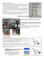
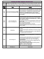
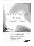
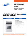
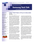
Fast Track Troubleshooting
IMPORTANT SAFETY NOTICE – “For Technicians Only” This service data sheet is
intended for use by persons having electrical, electronic, and mechanical experience
and knowledge at a level generally considered acceptable in the appliance repair trade.
Any attempt to repair a major appliance may result in personal injury and property
damage. The manufacturer or seller cannot be responsible, nor assume any liability for
injury or damage of any kind arising from the use of this data sheet.
Model:
FX510BGS/XAA
FX710BGS/XAA
Publication # tsFXx10 Revision Date 12/2/2011
WARNING
WARNING
CAUTION
Disconnect power before servicing the
range. Replace all panels before operating range. Failure to do so can result in
death or electrical shock.
EXPLOSION, FIRE, AND ASPHYXIATION
HAZARD
Shut off gas supply to the range before servicing. Check all gas lines and fittings for leaks
before operating the range. Replace all panels
before operating range. Failure to do so can
result in death or personal injury from explosion, fire, or asphyxiation.
When you work on the gas
range, be careful when handling sheet metal parts. Sharp
edges may be present, and you
can cut yourself if you are not
careful.
Operation Notes:
Convection Fan Operation - During normal Oven operation, the Convection Fan for
both the FX510 and the FX710 will cycle on and off. The ‘on’ time is ~ 10 secs. The
‘off’ time will vary from ~ 40 to 60 secs. This is normal operation and does not require
any service action.
Checking Error Codes:
There are two kinds of error codes. One denotes an oven temperature sensor error and the other denotes a safety error. Possible error codes during use can be checked before service.
1. Press Clock pad to select “AM” or “PM”. Each time the pad is pressed, the display toggles to the other setting.
The default setting is “PM”
2. Press the number pads 1,2,3 and 4. Make sure the Kitchen Timer and Warming Drawer are both turned OFF.
3. Press the Start pad.
4. Press the Custom Cook and the 0 number pads at the
same time for 2 seconds. Error codes are displayed.
5. Press the 0 number pad, to display the latest 5 error codes.
If the power is interrupted and the oven turns off, the stored error codes are deleted.
6. Press the Clear/Off pad to return to normal display mode.
Gas Range Components
Components
Door Lock Mtr 120vac
120vac
Conv Fan
120vac
Sub Fan
1750 ~ 1850Ω
20 ~ 30Ω
85 ~ 100Ω
Oven Temp Sensor Resistance Chart
Degree ºF
Ω
Degree ºF
Ω
0
932.12
104
1151.38
14
961.86
113
1170.17
23
980.95
122
1188.93
32
1000
212
1374.93
41
1019.02
302
1558.01
50
1038.02
392
1738.06
59
1056.99
482
1915.39
Component
Broil H S I
Bake H S I
Convect
Warm Dr
Oven Elements
Voltage
Current Ω @ Room Temp
120vac 3.2 – 3.6A
40 ~ 400Ω
120vac 3.2 – 3.6A
40 ~ 400Ω
(FX710BGS/XAA ONLY)
240vac
800 W
70 ~ 73Ω
120vac
600 W
22 ~ 25Ω
SUPPORT INFORMATION
Training — Plus One
http://my.plus1solutions.net/
Not Present on
FX510
FX-710 Control PCB
CN301, Membrane
Keypad Connector
CN101 Power Connector
CN401, Oven Sensor
120VAC(L1-N)
CN601 Relay Connector
Convection Fan Motor
Door Lock Motor
CN501 Door and Door
Lock switches Connector
TC601, 603 L1 120VAC
Terminal
TC602, N Terminal
Oven Lamp
T607, Conv. Heat Relay
T606, W/Drawer Relay
T604, Broil ingnitor Relay
T605, Bake Ingnitor Relay
FX-510 Control PCB
CN101 Power Connector
CN301, Membrane
Keypad Connector
CN601 Relay Connector
Convection Fan Motor
Door Lock Motor
Oven Lamp
120VAC(L1-N)
CN401, Oven Sensor
CN501 Door and Door
Lock switches Connector
TC601, 603 L1 120VAC
Terminal
TC602, N Terminal
T604, Broil ingnitor Relay
T605, Bake Ingnitor Relay
Natural Gas to LP Conversion :
The natural gas to LP conversion kit that is included with the range contains an
orifice for the oven bake and broil burners, each of the surface burners and in the
case of the FX710 that has a dual burner (right front), two orifices of different
sizes. The FX510 does not have the dual burner.
All orifices must be replaced with the proper size orifice. Each is stamped with the
size and is color coded. The color on the orifice corresponds with the color of the
gas valve that controls the burners and the face of the orifice is stamped with the
color as well.
After replacing the surface burner orifices, there are no adjustments necessary to
the burners. If the burner flame is not correct, too high or too low, after verifying
the correct orifice is installed the gas valve can be adjusted.
FX710 Natural Gas to LP Gas Conversion Kit
supplied with the range (FX510 similar)
Main Gas Valve Conversion:
The LP conversion requires this regulator to be set for different
pressures as LP gas is operated at higher pressures than natural
gas.
From inside the warming / storage drawer reach in and open the
red cap on the regulator. Using a 5/8” socket, open end wrench or
adjustable wrench, remove the LP regulator stud and set it to the
correct position.
The default position of the regulator is set for natural gas. To convert to LP remove the brass regulator using a 5/8” wrench or
socket and turn it upside down
Oven Burner Adjustment.
To adjust the shutter, loosen the locking screw and rotate the shutter towards the
open or closed position as needed. If flames are lifting off the burner ports, gradually
reduce the air shutter opening until the flames are stabilized.
If flames are too yellow and/or too large, gradually increase the air shutter opening
until the flames have approximately a 1-in blue cone.
If the range is set up for natural gas, the flames should burn with no yellow tipping.
If the range is set up for LP gas, small yellow tips at the end of the cones are normal.
After the flames are adjusted properly, shut off the oven, retighten the locking screws,
replace the oven bottom and racks.
Samsung 'Gas Range' Diagnostic Code Quick Guide
Display POWER LOSS CLEARS CODES 1)Press Clock AM/PM pad. 2) Press pad again, select AM. 3)Press # 1
Failure -2-3-4 pads. 4)Press the Start pad. 5)Press Custom Cook & # 0 pads simultaneously for 2 seconds. 6)
Codes
error codes will display. 7) Press number 0 pad to review last 5 codes. 8) Press Clear/Off to exit.
Failure
Code
E27
E28
E-08
E-0A
SE
Cause
Solution
Oven sensor opened (over 2950Ω)
Oven sensor shorted (Under 930Ω)
1. Disconnect power. Remove the upper rear cover. Disconnect
sensor harness from control Measure sensor resistance :1080Ω
at room temperature → If different value, replace oven sensor.
2. If there is not any problem with oven sensor, Please check
whether there is a damaged terminal or wire on harness.
3. Check resistance of oven sensor connector on main PCB
(Normal:2850Ω)
Oven not heating error
Oven over heating error
1. Disconnect power. Open the back cover. Disconnect the two
harness connectors to the oven temperature sensor. Measure
sensor resistance :1080Ω at the room temperature → If different
value, replace oven sensor.
2. Check the broil, bake and convection heater. Check the resistance of each.
3. Check whether DLB of sub PCB, Broil, Bake and Convection
heater relay are being activated
4. Check wiring harnesses between main PCB.
5. Check the resistance of oven sensor connector on main PCB.
(Normal : 2850Ω)
Shorted key
1. Check if cable of keypad has been inserted into connector of
main PCB.
2. Check for short between main PCB and connector or keypad
and cable.
3. If there is not a problem with connector on main PCB and cable of keypad, replace the main PCB.
1, Press and hold Cook Time & Delay Start for 3 seconds to test
motor operation.
E-OE
Door locking error
E-53
EEPROM error
2. Disconnect power. Open the back cover. Check wiring harness connections between door lock switch and motor.
3. Check resistance of door lock motor ,1750~1850Ω at the
room temperature.
4. With operating door lockout, measure voltage at door lock
motor. (Normal Voltage : AC 120V)
5. Check whether door locking switch is operating properly.
6. Measure resistance CN501 on PCB.
(COM-NO: ∞ at the room temperature)
*COM : Yellow Wire *NO : White Wire
Replace PCB
Non Error Code Troubleshooting
Failure
Cause
Solution
Warming drawer heater is not working.
(FX710 Only
Measure the resistance of the
warming drawer heating element.
Normal: ~24Ω
Replace the warming drawer heater
Check the warming drawer terminal on
the main board and the element (T606)
Clean connections
Replace the main Board
Check the warming drawer relay
(RY605) on the PCB.
Measure the voltage to the heating element
Normal: 120VAC
Convection fan not working
Measure the resistance of the convection fan motor.
Normal: ~26 Ω
Replace the fan motor
Clean connections
Replace the main board
Measure the voltage to the fan motor
Normal: 120VAC
Check the connections to the fan motor
Check the fan relay (RY607) on the
main board.
Convection heater not working
(FX710 only)
Measure the resistance of the convection heating element
Normal: ~18 Ω
Replace the warming drawer heater
Clean connections
Replace the main board
Measure the voltage to the heater
Normal: 120VAC
Check the connections to the heater
and the main board (T607)
Check the heater relay (RY606) on the
main board.
None of the surface burners will light
Check the gas supply to the range
Open the gas valve to the range
Check for burner spark
Check the igniter switches—Turn the
gas off and disconnect the electric to
the range. Turn the igniter switches one
by one to the 11:00 position to simulate
“Lite” and measure the resistance of
the switches at the spark module.
Check the igniter switch connection at
the spark module
Normal: 0Ω (only in this position)
Check the spark module
Only one of the surface burners will not
light
Because of the placement of the orifice,
even though the burner cup is protected, it is possible for spillage to get
into the cup and block the nozzle
All surface burners will light but will
not stay lit
Check for crimped or restricted gas
lines to the surface burner manifold
Check the main gas supply valve is
turned on completely
Check the LP converter in the regulator
to make sure it is in the correct position
Clean or replace the orifice with the correct Size.
Oven Temperature Errors
Failure
Cause
Solution
Burner will not light
Check the HSI (Igniter)
Replace the Igniter
Check the wiring to the HSI
Reseat or repair the
Check the connections to the safety wiring
valve
Wire the safety valve
Check that the safety valve is wired
correctly
correctly
Burner will light but not stay lit
Check the connections to the safety Reseat or repair the
valve
wiring
Check that the safety valve is wired
Wire the safety valve
correctly
correctly
Check that the burners have the
correct orifice size for the gas being Place the regulator LP
used
converter in the correct
Check the air adjustments for
position for the gas
proper flame
being used
Check that the regulator has the
correct position of the LP converter
Using the Bake or Broil function the
oven does not seem to be heating
correctly
(The measured temperature in the
oven does not match the display)
Check the connections to the temperature sensor
Check the resistance of the temperature sensor
Check for any stored errors
Check that the burners have the
correct orifice size for the gas being
used
Reseat or repair the wiring
Check that the burners have the
correct size orifice for the gas being
used.
Place the regulator LP converter in
the correct position for the gas being used
Check the air adjustments for
proper flame
Check that the regulator has the
correct position of the LP converter
Note: If the temperature is more that 15 degrees off from the display, it is possible that the temperature sensor
has changed value. If the sensor changes value the oven display will be set to the desired temperature but the
actual temperature in the oven cavity will be different. If the temperature in the oven compartment is slightly off
the user has the ability to offset the temperature ±30 degrees as outlined in the owner's manual. More than that,
suspect a sensor that has changed but is not bad enough to display an error.
The hot surface igniter will not come
on:
Check the igniter with a meter, you
should have continuity through the
HSI. If open replace the HSI.
HSI’s do weaken and will eventually
generate less heat than they normally could. When this happens
they can still allow marginally correct current to flow to the oven gas
valve for it to open but not get quite
hot enough to ignite the gas burner
immediately. When this happens,
gas released
into the oven can
sometimes build up to the point
where when finally ignited, the
amount of gas lit can cause a small
explosion inside the oven or cause
an odor of gas without the oven
working