1
Copyright
© Leaf Imaging Ltd., 20. All rights reserved.
This document is also distributed in Adobe Systems Incorporated's PDF
(Portable Document Format). You may reproduce the document from the
PDF file for internal use. Copies produced from the PDF file must be
reproduced in whole.
Trademarks
Adobe, Acrobat, Adobe Illustrator, Distiller, Photoshop, PostScript, and
PageMaker are trademarks of Adobe Systems Incorporated.
Apple, AppleShare, AppleTalk, iMac, ImageWriter, LaserWriter, Mac OS,
Power Macintosh, and TrueType are registered trademarks of Apple
Computer, Inc. Macintosh is a trademark of Apple Computer, Inc., registered
in the U.S.A. and other countries.
FCC Compliance
Any Leaf Imaging Ltd. equipment referred to in this document complies with
the requirements in part 15 of the FCC Rules for a Class A digital device.
Operation of the Leaf Imaging Ltd. equipment in a residential area may
cause unacceptable interference to radio and TV reception, requiring the
operator to take whatever steps are necessary to correct the interference.
Equipment Recycling
In the European Union, this symbol indicates that when the last user
wishes to discard this product, it must be sent to appropriate
facilities for recovery and recycling.
This electronic information product complies with Standard SJ/T
11363 - 2006 of the Electronics Industry of the People's Republic of
China.
Limitation of Liability
The product, software or services are being provided on an "as is" and "as
available" basis. Except as may be stated specifically in your contract, Leaf
Imaging Ltd. expressly disclaims all warranties of any kind, whether express
or implied, including, but not limited to, any implied warranties of
merchantability, fitness for a particular purpose and non-infringement.
You understand and agree that, except as may be stated specifically in your
contract, Leaf Imaging Ltd. shall not be liable for any direct, indirect,
incidental, special, consequential or exemplary damages, including but not
limited to, damages for loss of profits, goodwill, use, data or other intangible
losses (even if Leaf Imaging Ltd. has been advised of the possibility of such
damages), resulting from: (i) the use or the inability to use the product or
software; (ii) the cost of procurement of substitute goods and services
resulting from any products, goods, data, software, information or services
purchased; (iii) unauthorized access to or alteration of your products,
software or data; (iv) statements or conduct of any third party; (v) any other
matter relating to the product, software, or services.
The text and drawings herein are for illustration and reference only. The
specifications on which they are based are subject to change. Leaf Imaging
Ltd. may, at any time and without notice, make changes to this document.
Leaf Imaging Ltd. assumes no liability for technical or editorial errors or
omissions made herein, and shall not be liable for incidental, consequential,
indirect, or special damages, including, without limitation, loss of use, loss or
alteration of data, delays, or lost profits or savings arising from the use of
this document.
http://www.leaf-photography.com
Copyright © 20 Leaf Imaging Ltd. All rights reserved.
(Internal 853-00991E Rev A) Revised 27 'HFHPEHU 2009
Limitation of Liability
Leaf Limited Warranty
Warranty Coverage
Leaf warrants the Leaf product against defects in materials and
workmanship for a period of one (1) year from the date of original retail
purchase. Should you discover a defect, Leaf will, as its option, repair or
exchange the Leaf product at no charge to you provided that you notify Leaf
during the warranty period.
Obtaining Warranty Service
In the event that you believe the Leaf product requires service, please call
your Leaf product specialist first. Often a Leaf product specialist can resolve
technical issues over the phone, thereby avoiding a return. If service is
required, your Leaf product specialist will provide an approval for that action.
To find your local Leaf representative go to: www.leaf-photography.com
Exclusions and Limitations
This warranty does not apply if the Leaf product has been damaged by
accident, installation, shipment, abuse, misuse, misapplication, neglect, fire,
water, lightning, or other acts of nature; by failure to follow supplied
instructions; or by modification or repair by unauthorized personnel.
Leaf shall not be liable for any indirect damages, including, without limitation,
lost profits, damage to other property caused by any defect in the Leaf digital
back, damages based upon inconvenience, loss of use of the Leaf digital
back, loss of time, commercial use, incidental and/or consequential
damages for the breach of any expressed or implied warranty, including
damage to property and, to the extent permitted by law, damages for
personal injury, even if Leaf has been advised of the possibility of such
damages.
The Leaf product may contain refurbished parts. Leaf warrants the
refurbished parts in Leaf products for a period of one year from the date of
original retail purchase.
THIS WARRANTY IS IN LIEU OF ALL WARRANTIES, WHETHER ORAL
OR WRITTEN, EXPRESSED OR IMPLIED. ALL EXPRESSED OR IMPLIED
WARRANTIES FOR THIS LEAF DIGITAL BACK, INCLUDING THE
IMPLIED WARRANTIES OF MERCHANTABILITY AND FITNESS FOR
PARTICULAR PURPOSE, ARE LIMITED TO THE WARRANTY PERIOD.
NO WARRANTIES, EXPRESSED OR IMPLIED, WILL APPLY AFTER THE
WARRANTY PERIOD.
For latest Leaf product news and updates, visit: www.leaf-photography.com
Contents
/($)/,0,7(':$55$17<,,,
INTRODUCTION .........................................................................................................1
ABOUT T HIS GUIDE .........................................................................................................2
PRODUCT OVERVIEW .......................................................................................................2
USING THE PORTABLE HARDWARE ................................................................3
ITEMS REQUIRED FOR THE INSTALLATION ......................................................................4
INSERTING THE COMPACT FLASH ....................................................................................7
REMOVING THE COMPACT FLASH...................................................................................8
INSERTING THE BATTERY ................................................................................................8
REMOVING THE BATTERY ...............................................................................................9
CONNECTING THE LEAF DIGITAL CAMERA BACK TO A POWER SUPPLY ...................10
USING THE STYLUS ........................................................................................................10
STORING THE LEAF APTUSII D IGITAL CAMERA BACK ...............................................11
CHARGING THE BATTERIES .............................................................................13
CHARGING THE BATTERIES ...........................................................................................14
CHARGING THE BATTERY USING THE HÄHNEL MCL103...........................................14
MAMIYA 645 AFD......................................................................................................16
BEFORE GETTING STARTED...........................................................................................17
ITEMS REQUIRED FOR THE INSTALLATION ....................................................................17
QUICK INSTALLATION REFERENCE ...............................................................................17
INSTALLATION PROCEDURES .........................................................................................19
INSTALLING THE FOCUSING SCREEN ............................................................................19
Attaching the Leaf Digital Camera Back to the Camera Body.........................20
Connecting the Cables ..........................................................................................21
Removing the Leaf Digital Camera Back from the Camera Body.....................21
MAMIYA RB................................................................................................................43
BEFORE GETTING STARTED...........................................................................................44
Items Required for the Installation ......................................................................44
QUICK INSTALLATION REFERENCE ...............................................................................44
INSTALLATION PROCEDURES .........................................................................................46
Installing the Frame Mask....................................................................................46
Attaching the Leaf Digital Camera Back to the Camera Body.........................47
Connecting the Cables ..........................................................................................49
Removing the Leaf Digital Camera Back from the Camera Body.....................50
MAMIYA RZ67/RZ67PROII/ RZ67PROIID ...........................................................51
BEFORE GETTING STARTED...........................................................................................52
Items Required for the Installation ......................................................................52
QUICK INSTALLATION REFERENCE ...............................................................................52
Contents
INSTALLATION PROCEDURES......................................................................................... 54
Installing the Focusing Screen Mask...................................................................54
Attaching the Leaf Digital Camera Back to the Camera Body.........................55
Removing the Leaf Digital Camera Back From the Camera Body...................58
LARGE FORMAT......................................................................................................59
BEFORE GETTING STARTED .......................................................................................... 60
Items Required for the Installation......................................................................60
QUICK INSTALLATION REFERENCE ............................................................................... 61
The Digital Camera Back on a Large Format Camera with a Rollei Electronic
Shutter ....................................................................................................................61
The Digital Camera Back on a Large Format Camera with a Schneider
Electronic Shutter..................................................................................................63
Using a Mechanical Shutter Lens ........................................................................63
WORKING IN TETHERED MODE......................................................................65
CONNECTING THE F IREW IRE CABLE ........................................................................... 66
ATTACHING THE REPEATER .......................................................................................... 67
CARING FOR THE IR FILTER GLASS .............................................................69
IMPORTANCE OF THE PROTECTIVE IR FILTER GLASS .................................................. 70
Cleaning the Protective IR Filter Glass ..............................................................71
1
Introduction
ABOUT T HIS GUIDE .........................................................................................................2
PRODUCT OVERVIEW .......................................................................................................2
This Guide
2
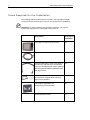
About This Guide
This guide includes the necessary instructions for installing a Leaf® Aptus II
digital camera back. Each stage in the installation process is explained in the
guide as follows:
Chapter 2 Using the Portable
Hardware.
Read this chapter to learn how to insert and
remove the compact flash FDUG
Chapter 3 Charging the Batteries
Read this chapter to learn how to charge the
batteries for both a compact flash FDUG
Chapter 4 Mamiya 645 AFD
Instructions on attaching the camera back to the
camera body and preparing the camera.
Chapter 5 Working in Tethered
Mode
Read this chapter to learn how to connect your
camera back to the computer
Chapter 6 Caring for the IR Filter
Glass
Read this chapter to learn how to clean the IR
filter glass that protects the sensor.
Product Overview
The Leaf AptusII digital camera back is the world’s first camera back that
includes a built-in large (6 x 7 cm) LCD and an innovative graphic user
interface. An integrated battery and compact flash (CF) storage card ensure
easy shooting. New hardware offers a continuous non-stop burst, and a
faster capture rate. These shooting capabilities combined with large storage
options give professionals the flexibility to meet the most demanding
shooting situations.
$QHZ5$: that uses lossless compression to reduce file size, and a
completely new Leaf Capture application enhance workflow and teamwork
both on location and in the studio.
Note: The Leaf Capture DQG&DSWXUH2QHapplicationV, supplied with
your Leaf AptusII digital camera back, enable you to capture, view,
and manipulate an image sothat you can produce a finished product in
a single session.
2
Using the Portable Hardware
ITEMS REQUIRED FOR THE INSTALLATION ......................................................................4
INSERTING THE COMPACT FLASH ....................................................................................7
REMOVING THE COMPACT FLASH...................................................................................8
INSERTING THE BATTERY ................................................................................................8
REMOVING THE BATTERY ...............................................................................................9
CONNECTING THE LEAF DIGITAL CAMERA BACK TO A POWER SUPPLY ...................10
USING THE STYLUS ........................................................................................................10
STORING THE LEAF APTUSII DIGITAL CAMERA BACK ...............................................11
Required for the Installation
4
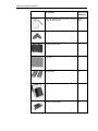
Items Required for the Installation
The following table describes what is included in the Leaf AptusII digital
camera back kit and which items in the kit are required for the installation.
Important! To avoid installation and operation problems, use only the
accessories supplied in the Leaf digital camera back kit.
Kit Contents
Required for
Installation
Leaf AptusII digital camera back
Yes
FireWire cable (4.5 m / 15 ft.)
Yes
Camera-to-Back Sync cable. This cable is Yes
included only with the kit for the following
cameras: Hasselblad (500 Series), Mamiya
RB, Mamiya RZ67/RZ67ProII/RZ67ProIID,
and large format.
Focusing screen or mask (not included with Yes
the Leaf AptusII digital camera back for
large format cameras)
Leaf Capture application and
accompanying documentation
Yes
4XLFNInstallation Guide
Yes
Using the Portable Hardware
5
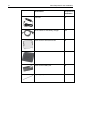
Kit Contents
Required for
Installation
Cleaning supplies (cleaning liquid, cleaning (.eep on
wipes, and tweezers)
hand)
External power adaptor
No
Protective Hard Case
No
Gray card
No
Two batteries
Yes
Fast charger for lithium ion batteries
Yes
12V DC power supply
Yes
Required for the Installation
6
Kit Contents
Required for
Installation
Car lead
No
Three cables for the battery charger
Yes
Cover for the LCD touch screen
No
Back cover
No
Cover for the battery slot
No
Stylus (spare)
No
Using the Portable Hardware
Inserting the Compact Flash card
1. Open the compact flash card door.
Open the door
Figure 2: The compact flash card door
2. Insert the compact flash card.
Compact flash
card
Figure 3: Insert the compact flash card
7
the Compact Flash card
8
Removing the Compact Flash card
Open the compact flash card door, and then press the release button.
Release button
Figure 4: The compact flash release button
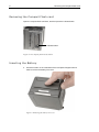
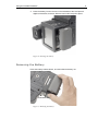
Inserting the Battery
3. Press the button on the underside of the Leaf AptusII digital camera
back to remove the battery slot cover.
Figure 5: Removing the battery slot cover
Using the Portable Hardware
9
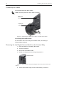
4. Press the battery into the recess on the underside of the Leaf AptusII
digital camera back, and then slide it across until it snaps into place.
Figure 6: Inserting the battery
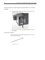
Removing the Battery
Press the battery release button, and then slide the battery out.
Release button
Figure 7: Removing the battery
the Leaf Digital Camera Back to a Power Supply
10
Connecting the Leaf Digital Camera Back to a Power
Supply
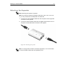
1. Insert the end of the external power adaptor into the FW port on the
/HDIAptusII digital camera back.
Figure 8: Insert the external power supply adaptor
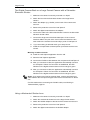
2. Connect the other end of the external power adaptor to the 12V DC
power supply.
Using the Stylus
The Leaf AptusII digital camera back is supplied with a stylus. Use the
stylus to tap the touch screen.
Figure 9: The stylus
Using the Portable Hardware
11
To remove the stylus for use, slide it out of the slot located at the top of the
Leaf AptusII digital camera back.
Figure 10: Removing the stylus
Storing the Leaf AptusII Digital Camera Back
To protect your digital camera back, store it in the case supplied. Ensure that
you place the digital camera back in the case with the sensor cover facing
upward.
3
Charging the Batteries
CHARGING THE BATTERIES ...........................................................................................14
CHARGING THE BATTERY USING THE HÄHNEL MCL103...........................................14
the Batteries
14
Charging the Batteries
You can charge the lithium ion battery used with the Leaf AptusII camera
back using the MCL103 battery charger provided. .
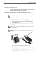
Charging the Battery Using the Hähnel MCL103
Attention: Before performing these procedures, refer to the Safety *XLGH
RQWKHDFFRPSDQ\LQJ&'.
To charge the battery with the 12V DC Power Supply:
1. Connect one end of the 12V DC power supply cable to the Kähnel
MCL103 battery charger.
2. Connect the 12V DC power supply to a wall outlet, using the cable
provided.
Note: The 12V DC power supply is designed for use with both 110V and
220V input voltages.
Attention: Do not use any power supply cables other than the cable
provided.
Figure 11: Connecting the hähnel MCL103 battery charger
3. Insert the battery with contacts facing down and slide the battery fully
down into the contacts.
Once charging begins, an indicator light turns on.
The indicator light begins to flash when the battery is almost charged.
Charging is complete when the indicator light turns off.
Charging the Batteries
15
Note: Do not leave the battery in the charger when the charger is not
connected to the power supply. This causes the battery to discharge.
To charge the battery with the car lead:
1. Connect one end of the car lead cable to the hähnel MCL103 battery
charger.
2. Connect the car lead to the 12V car socket.
To remove the battery pack from the charger:
Slide the battery off the charger.
Warning! Use only the supplied 12V DC power supply or 12V car lighter
adaptor.
Warning! Never apply excessive force when connecting or disconnecting a
battery.
Warning! Keep all contacts clean.
Warning! Do not force down any of the contacts.
Warning! Do not short circuit the contacts.
Warning! Never store the battery connected to the charger for an extensive
period of time.
Warning! Do not expose to excessive heat or naked flame.
Warning! Do not dismantle the product or alter it in any way.
4
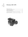
Mamiya 645 AFD
BEFORE GETTING STARTED .......................................................................................... 17
ITEMS REQUIRED FOR THE INSTALLATION ................................................................... 17
QUICK INSTALLATION REFERENCE ............................................................................... 17
INSTALLATION PROCEDURES......................................................................................... 19
INSTALLING THE FOCUSING SCREEN ............................................................................ 19
ATTACHING THE LEAF DIGITAL CAMERA BACK TO THE CAMERA BODY ................. 20
CONNECTING THE CABLES ............................................................................................ 21
REMOVING THE LEAF DIGITAL CAMERA BACK FROM THE CAMERA BODY .............. 21
Mamiya 645 AFD
17
Before Getting Started
This chapter describes the Leaf AptusII digital camera back installation for
the Mamiya 645 AFD camera.
Items Required for the Installation
For a detailed list of the items required for installation, see Items Required
for the Installation, page 4.
Important! To avoid installation and operation problems, use only the
accessories supplied in the Leaf AptusII digital camera back kit.
Quick Installation Reference
1. Charge the batteries.
2. Install the focusing screen.
3. Remove the protective cover from the digital camera back and mount
the back onto the camera body. If you are working in tethered mode, go
straight to step 5.
4. Install the compact flash card. The installation is complete.
Working in tethered mode:
5. Install the Leaf Capture application from the CD.
6. Start the Leaf Capture application.
7. Connect the FireWire cable between the computer and Leaf AptusII.
8. After you connect the cable, the application automatically connects to
the digital camera back. When the connection is established, the LED
indicator on the digital camera back turns from orange to green.
Note: If you want to work with an external flash or strobe, connect the Flash
Sync cable between the camera and the flash or strobe unit.
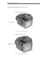
18
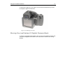
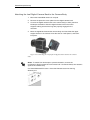
2
3
1
4
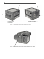
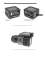
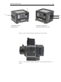
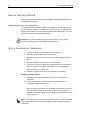
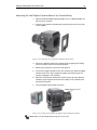
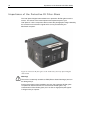
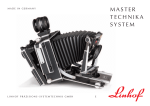
[1] Flash Sync socket
[2] FireWire port
[3] Camera Control socket
[4] Camera-to-Back Sync socket
Figure 12: The Leaf AptusII digital camera back ports and sockets
Figure 13: The Leaf AptusII digital camera back on a Mamiya 645 AFD camera
Mamiya 645 AFD
19
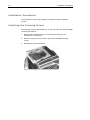
Installation Procedures
The procedures in this section together constitute the basic installation
process.
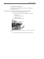
Installing the Focusing Screen
The focusing screen enables you to view the exact area that the Leaf Aptus,,
digital camera back captures. Before you can install the supplied focusing
screen, you must remove the camera’s original focusing screen.
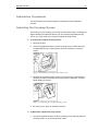
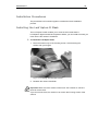
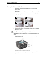
To remove the original focusing screen:
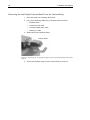
1. Remove the lens.
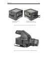
2. Using the supplied tweezers, pull the focusing screen release lever [A]
located inside the lens mount (upper center) to release the focusing
screen.
Figure 14: Pulling the focusing screen release lever
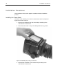
3. Remove the original focusing screen from the focusing screen frame by
grasping the tab on the edge of the screen with the tweezers, and then
gently pulling up and out.
Figure 15: Removing the original focusing screen
4. Be careful not to touch or damage the mirror.
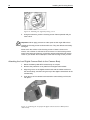
To attach the supplied focusing screen:
1. Using the supplied tweezers, hold the focusing screen tab and place the
focusing screen on the focusing screen frame.
20
Installing the Focusing Screen
Figure 16: Installing the supplied focusing screen
2. Using the tweezers, push the focusing screen frame upwards until you
hear a click.
Important: Never apply pressure on other parts as this might affect focus.
Handle the focusing screen surfaces with care. They are delicate and easily
damaged.
Never touch the surface of the focusing screen. If there is dust on the
screen, use a blower or soft lens brush to remove it. If the focusing screen
needs more thorough cleaning, contact the nearest authorized /HDIVHUYLFH
centerRU\RXUGHDOHU. Do not attempt to clean the focusing screen yourself.
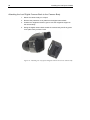
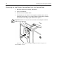
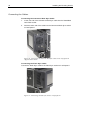
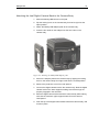
Attaching the Leaf Digital Camera Back to the Camera Body
1. Mount the Mamiya 645 AFD camera body on a tripod.
2. Remove the protective cover plate from the digital camera back.
3. Align the groove on the digital camera back with the holder bracket on
the camera body, and then bring the top of the digital camera back to the
camera body.
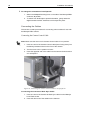
4. Push the top of the camera back toward the camera body until it locks
into place.
Figure 17: Attaching the Leaf AptusII digital camera back to a Mamiya 645
camera body
Mamiya 645 AFD
21
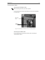
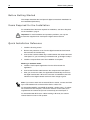
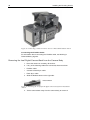
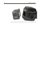
Connecting the Cables
Connecting the Flash Sync Cable
If you want to use flash or strobe lighting, connect the Flash Sync cable to
the Flash Sync socket of the Mamiya 645 AFD camera.
Flash Sync
Socket
Flash Sync
Cable
Figure 18: Connecting the Flash Sync cable to the Mamiya 645 AFD camera
Connecting the FireWire Cable
For information about connecting the FireWire cable, see Working in
Tethered Mode, page 65.
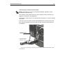
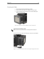
Removing the Leaf Digital Camera Back from the Camera Body
1. Place the camera on a steady, flat surface.
2. Turn the camera off.
3. Disconnect the FireWire cable.
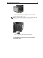
4. Slide and push the Release button.
Release Button
Figure 19: Removing the Leaf AptusII digital camera back from a Mamiya 645
AFD camera
5. Tilt the camera back away from the camera body to remove it.
5
22
Installing the Focusing Screen
Hasselblad H1
BEFORE GETTING STARTED .......................................................................................... 23
ITEMS REQUIRED FOR THE INSTALLATION ................................................................... 23
QUICK INSTALLATION REFERENCE ............................................................................... 23
INSTALLATION PROCEDURES......................................................................................... 25
INSTALLING THE LEAF APTUSII MASK ........................................................................ 25
ATTACHING THE LEAF DIGITAL CAMERA BACK TO THE CAMERA BODY ................. 26
CONNECTING THE CABLES ............................................................................................ 27
REMOVING THE LEAF DIGITAL CAMERA BACK FROM THE CAMERA BODY .............. 28
Hasselblad H1
23
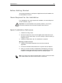
Before Getting Started
This chapter describes the Leaf AptusII digital camera back installation for
the Hasselblad H1 camera.
Items Required for the Installation
For a detailed list of the items required for installation, see Items Required
for the Installation, page 4.
Important! To avoid installation and operation problems, use only the
accessories supplied in the Leaf AptusII digital camera back kit.
Quick Installation Reference
1. Install the focusing screen.
2. Remove the protective cover from the digital camera back and mount
the back onto the camera body. If you are working in tethered mode, go
straight to step 4.
3. Install the compact flash card. The installation is complete.
Working in tethered mode:
4. Install the Leaf Capture application from the CD and start the
application.
5. Connect the FireWire cable between the computer and Leaf AptusII.
6. After you connect the cable, the application automatically connects to
the digital camera back. When the connection is established, the LED
indicator on the digital camera back turns from orange to green.
Note: If you want to work with an external flash or strobe, connect the Flash
Sync cable between the camera and the flash or strobe unit.
24
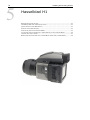
2
1
3
4
[1] Flash Sync socket
[2] FireWire port
[3] Camera Control socket
[4] Camera-to-Back Sync socket
Figure 20: The Leaf AptusII digital camera back ports and sockets
Figure 21: The Leaf AptusII digital camera back on a Hasselblad H camera
Hasselblad H1
25
Installation Procedures
The procedures in this section together constitute the basic installation
process.
Installing the Leaf AptusII Mask
The Leaf AptusII mask enables you to view the exact area that the
/HDIAptusII digital camera back captures. Before you can install the mask, you
must remove the camera’s viewfinder.
To install the Leaf Aptus mask:
1. Place the mask on top of the focusing screen. Avoid touching the
surface with your fingers.
Figure 22: Inserting the Leaf Aptus mask
2. Reattach the camera viewfinder.
Important! Never touch the surface of the mask. Use a blower or soft lens
brush to remove dust.
If you remove the mask, be careful not to scratch the focusing screen of the
camera.
26
Installing the Leaf AptusII Mask
Attaching the Leaf Digital Camera Back to the Camera Body
1. Mount the camera body on a tripod.
2. Remove the protective cover plate from the digital camera back.
3. Position the magazine retention groove onto the magazine support on
the camera body.
4. Swing the digital camera back toward the camera body and firmly press
it into place until you hear a click.
Figure 23: Attaching the Leaf AptusII digital camera back to the camera body
Hasselblad H1
27
Connecting the Cables
Connecting the Flash Sync Cable
Note: Connecting the Flash Sync cable is optional.
Connect the Flash Sync cable to the Flash Sync socket of the Hasselblad
H1 camera body.
Flash Sync
Socket
Flash Sync
Cable
Figure 24: Connecting the Flash Sync cable to the Hasselblad H1
Connecting the FireWire Cable
For information about connecting the FireWire cable, see Working in
Tethered Mode, page 65.
28
Installing the Leaf Aptus-II Mask
Removing the Leaf Digital Camera Back from the Camera Body
1. Place the camera on a steady, flat surface.
2. Turn the camera off.
3. Disconnect the FireWire cable.
4. Press gently on the center of the magazine release button, twist it
clockwise until it stops (1), and then press the button firmly inwards
toward the camera body (2) to release Leaf Aptus-II.
Important! Make sure to press on the center of the magazine release
button, not on the lever.
Figure 25: Removing the Leaf Aptus-II digital camera back from a a
Hasselbald H1 camera
6
Hasselblad (500 Series)
BEFORE GETTING STARTED...........................................................................................30
ITEMS REQUIRED FOR THE INSTALLATION ....................................................................30
QUICK INSTALLATION REFERENCE ...............................................................................30
INSTALLATION PROCEDURES .........................................................................................32
INSTALLING THE FOCUSING SCREEN ............................................................................32
ATTACHING THE LEAF DIGITAL CAMERA BACK TO THE CAMERA BODY .................33
CONNECTING THE CABLES ............................................................................................34
REMOVING THE LEAF DIGITAL CAMERA BACK FROM THE CAMERA BODY ..............36
30
Before Getting Started
Before Getting Started
This chapter describes the Leaf AptusII digital camera back installation for
the Hasselblad (500 series).
Items Required for the Installation
For a detailed list of the items required for installation, see Items Required
for the Installation, page 4.
Important! To avoid installation and operation problems, use only the
accessories supplied in the Leaf AptusII digital camera back kit.
Quick Installation Reference
1. Install the focusing screen.
2. Remove the protective cover from the digital camera back and mount
the back onto the camera body.
3. Connect the Camera-to-Back Sync cable between the camera lens and
Leaf Aptus,,. If you are working in tethered mode, go straight to step 5.
4. Install the compact flash card. The installation is complete.
Working in tethered mode:
5. Install the Leaf Capture application from the CD and start the
application.
6. Connect the FireWire cable between the computer and Leaf AptusII.
7. After you connect the cable, the application automatically connects to
the digital camera back. When the connection is established, the LED
indicator on the digital camera back turns from orange to green.
Note: If you want to work with an external flash or strobe, connect the Flash
Sync cable between the camera and the flash or strobe unit.
For Hasselblad 553ELX, and 500EL/M, 503CW + winder users—To trigger
the camera from the computer, connect the Camera Control cable (not
supplied with the camera back) to the camera body and Leaf Aptus,,.
For Hasselblad 555 ELD users—When working in B-mode, the camera
release button must be in Film position.
Hasselblad (500 Series)
31
2
1
3
4
[1] Flash Sync socket
[2] FireWire port
[3] Camera Control socket
[4] Camera-to-Back Sync socket
Figure 26: The Leaf AptusII digital camera back ports and sockets
Figure 27: The Leaf AptusII digital camera back with a Hasselblad (500 series)
camera
32
Installation Procedures
Installation Procedures
The procedures in this section together constitute the basic installation
process.
Installing the Focusing Screen
The focusing screen mask enables you to view the exact area that the digital
camera back captures.
1. Remove the viewfinder from the camera body according to the
manufacturer’s instructions.
2. Place the focusing screen mask on top of the Hasselblad focusing
screen.
3. Reinstall the camera viewfinder.
Figure 28: Installing Hasselblad focusing screen mask
Hasselblad (500 Series)
33
Attaching the Leaf Digital Camera Back to the Camera Body
1. Mount the Hasselblad camera on a tripod.
2. Remove the protective cover plate from the digital camera back.
3. Connect the digital camera back to the camera body in either portrait or
landscape orientation. Rest the digital camera back on the lower
supports making sure that the lugs are properly engaged in the
recesses.
4. Move the digital back toward the camera body and check that the upper
support hooks on the camera fit into the slots on Leaf Aptus,,, and lock it
into place.
Figure 29: Connecting the Leaf AptusII digital camera back to the camera
body
Notes: To switch from landscape to portrait orientation, remove the
/HDIAptusII digital camera back and rotate it 90° counterclockwise, then attach it
again to the camera body.
For Hasselblad 555 ELD users—Insert the Release button into the Dig
Release port.
34
Installing the Focusing Screen
Connecting the Cables
Connecting the Camera-to-Back Sync Cable
1.
Insert one end of the Camera-to-Back Sync cable into the Hasselblad
Lens Flash socket.
2. Insert the other end of the cable into the Camera-to-Back Sync socket
on Leaf AptusII.
Figure 30: Connecting a Camera-to-Back Sync cable to the Leaf AptusII
digital camera back
Connecting the Flash Sync Cable
Connect the Flash Sync cable to the Flash Sync socket on Leaf Aptus,,.
Figure 31: Connecting a Flash Sync cable to Leaf AptusII
Hasselblad (500 Series)
35
Connecting the Camera Control Cable
Notes: This section is for users of Hasselblad 553ELX, 503CW + winder,
and 503EL-M cameras only.
The Camera Control cable should be used in Remote mode only when you
trigger the camera from the application.
The Camera Control cable is not supplied with Leaf Aptus,,. It can be ordered
separately
Insert one end of the cable into the Hasselblad Remote Control socket, and
then insert the opposite end of the cable into the Camera Control socket on
Leaf AptusII.
Camera Control
Socket
Remote Control
Socket
Figure 32: Connecting a Camera Control cable to a Hasselblad 553ELX/500
EL-M camera
36
Installing the Focusing Screen
Figure 33: Connecting a Camera Control cable to a Hasselblad 503CW camera
Connecting the FireWire Cable
For information about connecting the FireWire cable, see Working in
Tethered Mode, page 65.
Removing the Leaf Digital Camera Back from the Camera Body
1. Place the camera on a steady, flat surface.
2. If any of the following cables are connected, disconnect them:
•
FireWire cable
•
Camera-to-Back Sync cable
•
Flash Sync cable
3. Slide the Release button to the right side.
Release Button
Figure 34: Removing the Leaf AptusII digital camera back from a Hasselblad
camera
4. Tilt the camera back away from the camera body to remove it.
7
Contax 645
BEFORE GETTING STARTED...........................................................................................38
ITEMS REQUIRED FOR THE INSTALLATION ....................................................................38
QUICK INSTALLATION REFERENCE ...............................................................................38
INSTALLATION PROCEDURES .........................................................................................40
INSTALLING THE FOCUSING SCREEN ............................................................................40
ATTACHING THE LEAF DIGITAL CAMERA BACK TO THE CAMERA BODY .................41
CONNECTING THE CABLES ............................................................................................42
REMOVING THE LEAF DIGITAL CAMERA BACK FROM THE CAMERA BODY ..............42
38
Before Getting Started
Before Getting Started
This chapter describes the Leaf AptusII digital camera back installation for
the Contax 645 camera.
Items Required for the Installation
For a detailed list of the items required for installation, see Items Required
for the Installation, page 4.
Important! To avoid installation and operation problems, use only the
accessories supplied in the Leaf AptusII digital camera back kit.
Quick Installation Reference
1. Install the focusing screen.
2. Remove the protective cover from the Leaf AptusII digital camera
back, and mount the back onto the camera body. If you are working
in tethered mode, go straight to step 4.
3. Install the compact flash card. The installation is complete.
Working in tethered mode:
4. Install the Leaf Capture application from the CD.
5. Start the Leaf Capture application.
6. Connect the FireWire cable between the computer and Leaf AptusII.
After you connect the cable, the application automatically connects to
the digital camera back. When the connection is established, the LED
indicator on the digital camera back turns from orange to green.
Note: If you want to work with an external flash or strobe, connect the Flash
Sync cable between the camera and the flash or strobe unit.
Contax 645 AF
39
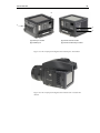
2
1
3
4
[1] Flash Sync socket
[2] FireWire port
[3] Camera Control socket
[4] Camera-to-Back Sync socket
Figure 35: The Leaf AptusII digital camera back ports and sockets
Figure 36: The Leaf AptusII digital camera back with a Contax 645
camera
40
Installation Procedures
Installation Procedures
The procedures in this section together constitute the basic installation
process.
Installing the Focusing Screen
The focusing screen enables you to view the exact area that the Leaf Aptus,,
digital camera back captures. Before you can install the supplied focusing
screen, you must remove the camera’s original focusing screen.
To remove the original focusing screen:
1. Remove the Contax viewfinder.
2. Pick up the screen frame claw with your finger tip, and pull it gently
upwards to remove the focusing screen.
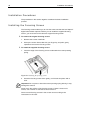
To install the supplied focusing screen:
1. Insert the edge of the focusing screen underneath the screen pressing
spring.
Figure 37: Installing the focusing screen
2. Press the focusing screen down gently, until it locks into place with a
click.
Important! Do not press or bend the screen pressing spring directly, it may
damage the camera.
Never touch the surface of the focusing screen. If there is dust on the
screen, use a blower or soft lens brush to remove it.
Store unused focusing screens in the screen case according to the
instructions on the case.
Contax 645 AF
41
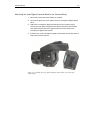
Attaching the Leaf Digital Camera Back to the Camera Body
1. Mount the Contax 645 camera body on a tripod.
2. Remove the protective cover plate from the Leaf AptusII digital camera
back.
3. Attach the Leaf AptusII digital camera back to the camera body by
moving the Leaf AptusII digital camera back toward the camera body
and check that the camera’s support hooks fit into the slots on the
/HDIAptusII digital camera back.
4. Push the top of the Leaf AptusII digital camera back toward the camera
body until it locks into place.
Figure 38: Attaching the Leaf AptusII digital camera back to a Contax 645
camera body
42
Installing the Focusing Screen
Connecting the Cables
Connecting the Flash Sync Cable
Note: Connecting the Flash Sync cable is optional.
Flash Sync
Socket
Flash Sync
Cable
Figure 39: Connecting the Flash Sync cable to a Contax 645 camera
Connecting the FireWire Cable
For information about connecting the FireWire cable, see Working in
Tethered Mode, page 65.
Removing the Leaf Digital Camera Back from the Camera Body
1. Place the camera on a steady, flat surface.
2. Turn the camera off.
3. Disconnect the FireWire cable.
4. Rotate the release button to the right and push it in.
Release Button
Figure 40: Removing the Leaf AptusII digital camera back from Contax 645
camera
5. Tilt the camera back away from the camera body to remove it.
8
Mamiya RB
BEFORE GETTING STARTED...........................................................................................44
ITEMS REQUIRED FOR THE INSTALLATION ....................................................................44
QUICK INSTALLATION REFERENCE ...............................................................................44
INSTALLATION PROCEDURES .........................................................................................46
INSTALLING THE FRAME MASK .....................................................................................46
ATTACHING THE LEAF DIGITAL CAMERA BACK TO THE CAMERA BODY .................47
CONNECTING THE CABLES ............................................................................................49
REMOVING THE LEAF DIGITAL CAMERA BACK FROM THE CAMERA BODY ..............50
44
Before Getting Started
Before Getting Started
This chapter describes the Leaf AptusII digital camera back installation for
the Mamiya RB camera.
Items Required for the Installation
For a detailed list of the items required for installation, see Items Required
for the Installation, page 4. In addition to the items shown, the Mamiya RB
digital camera back kit also includes the Mamiya RB adaptor plate. You will
need the plate for the installation procedure.
Important! To avoid installation and operation problems, use only the
accessories supplied in the Leaf digital camera back kit.
Quick Installation Reference
1. Install the focusing screen mask into the viewfinder.
2. Mount the adaptor plate on the camera body.
3. Remove the protective cover from the Leaf AptusII digital camera
back.
4. Attach the digital camera back to the adaptor plate.
5. Connect the Camera-to-Back Sync cable between the camera lens
and the Leaf AptusII digital camera back. If you are working in
tethered mode, go to step 7 now.
6. Install the compact flash card. The installation is complete.
Working in tethered mode:
7. Install the Leaf Capture application from the CD and start the
application.
8. Connect the FireWire cable between the computer and the
/HDIAptusII digital camera back.
After you connect the cable, the application automatically connects
to the Leaf AptusII digital camera back. When the connection is
established, the LED indicator on the digital camera back turns from
orange to green.
Note: If you want to work with an external flash or strobe, connect the Flash
Sync cable between the Leaf AptusII digital camera back and the flash or
strobe unit.
Mamiya RB
45
2
1
3
4
[1] Flash Sync socket
[2] FireWire port
[3] Camera Control socket
[4] Camera-to-Back Sync socket
Figure 41: Ports and sockets on the Leaf AptusII digital camera back
Figure 42: The Leaf AptusII digital camera back on a Mamiya RB camera
46
Installation Procedures
Installation Procedures
The procedures in this section together constitute the basic installation
process.
Installing the Frame Mask
The frame mask enables you to view the exact area that the Leaf AptusII
digital camera back captures.
1. Remove the viewfinder from the camera body according to the
manufacturer’s instructions.
2. Place the frame mask on top of the Mamiya RB focusing screen.
Figure 43: Installing the focusing screen mask
3. Reinstall the viewfinder on the camera body according to the
manufacturer’s instructions.
Mamiya RB
47
Attaching the Leaf Digital Camera Back to the Camera Body
1. Mount the Mamiya RB camera on a tripod.
2. Flip the locking lever on the camera body from left to right into the
Open position.
3. Attach the Mamiya RB adaptor plate to the camera body.
4. Insert the four studs on the adaptor into the four holes on the
camera body.
Figure 44: Attaching the Mamiya RB adaptor plate
5. Secure the adaptor plate to the camera body by flipping the locking
lever on the camera body from right to left into the Locked position.
6. Remove the protective cover from Leaf AptusII.
7. Connect the digital camera back to the camera body. Rest the digital
camera back on the lower supports making sure that the lugs are
properly engaged in the recesses.
8. Move the digital camera back toward the camera body while making
sure that the camera’s upper support hooks fit into the slots on
/HDIAptusII.
9. Push the top of the digital camera back toward the camera body until
it locks in place.
48
Installation Procedures
Figure 45: Attaching the Leaf AptusII digital camera back to a Mamiya RB camera
Mamiya RB
49
Connecting the Cables
1. Connecting the Camera-to-Back Sync Cable
2. Insert one end of the cable into the Mamiya Lens Flash socket.
3. Insert the opposite end of the cable into the Camera-to-Back Sync
socket on the adaptor plate.
Figure 46: Connecting a Camera-to-Back Sync cable to Leaf AptusII
Connecting the Flash Sync Cable
Note: You can use only external flash or strobe light with Leaf AptusII.
Connect the Flash Sync cable to the Flash Sync connector on Leaf AptusII.
Figure 47: Connecting a Flash Sync cable to the Leaf AptusII digital camera back
50
Installation Procedures
Connecting the FireWire Cable
For information about connecting the FireWire cable, see Working in
Tethered Mode, page 65.
Removing the Leaf Digital Camera Back from the Camera Body
1. Place the camera on a solid, steady surface.
2. If any of the following cables are connected, disconnect them:
•
FireWire cable
•
Camera-to-Back Sync cable
•
Flash Sync cable
3. Slide and push the Release button.
Release Button
Figure 48: Removing the Leaf AptusII digital camera back from a Mamiya RB
camera
4. Tilt the camera back away from the camera body to remove it.
5
Mamiya RZ67/RZ67ProII/
RZ67ProIID
BEFORE GETTING STARTED...........................................................................................52
ITEMS REQUIRED FOR THE INSTALLATION ....................................................................52
QUICK INSTALLATION REFERENCE ...............................................................................52
INSTALLATION PROCEDURES .........................................................................................54
INSTALLING THE FOCUSING SCREEN MASK .................................................................54
ATTACHING THE LEAF DIGITAL CAMERA BACK TO THE CAMERA BODY .................55
REMOVING THE LEAF DIGITAL CAMERA BACK FROM THE C AMERA BODY .............58
52
Before Getting Started
Before Getting Started
This chapter describes the Leaf AptusII digital camera back installation for
the Mamiya RZ67, Mamiya RZ67ProII, and Mamiya RZ67 ProIID cameras.
Items Required for the Installation
For a detailed list of the items required for installation, see Items Required
for the Installation, page 4. In addition to the items shown, your kit will
include the Mamiya RZ67 adaptor plate. You will need the adaptor plate for
the installation procedure.
Important! To avoid installation and operation problems, use only the
accessories supplied in the Leaf digital camera back kit.
Quick Installation Reference
1. Install the focusing screen mask into the viewfinder.
2. Mount the adaptor plate on the camera body.
3. Remove the protective cover from the Leaf AptusII digital camera
back.
4. Attach the digital camera back to the adaptor plate.
5. Connect the Camera-to-Back Sync cable between the camera lens
and Leaf AptusII. If you are working in tethered mode, go straight to
step 7.
6. Install the compact flash card. The installation is complete.
Working in tethered mode:
7. Install the Leaf Capture application from the CD and start the
application.
8. Connect the FireWire cable between the computer and Leaf AptusII.
After you connect the cable, the application automatically connects
to the digital camera back. When the connection is established, the
LED indicator on the digital camera back turns from orange to green.
Note: If you want to work with an external flash or strobe, connect the Flash
Sync cable between the Leaf AptusII digital camera back and the flash or
strobe unit.
Note: To trigger the camera from the computer, connect the Camera Control
cable (not supplied with the camera back) between the camera body and
Leaf AptusII.
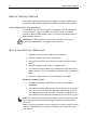
Mamiya RZ67/RZ67ProII/ RZ67ProIID
53
2
1
3
4
[1] Flash Sync socket
[2] FireWire port
[3] Camera Control socket
[4] Camera-to-Back Sync socket
Figure 49: Ports and sockets on the Leaf AptusII digital camera back
Figure 50: The Leaf AptusII digital camera back on a Mamiya RZ67 camera
54
Installation Procedures
Installation Procedures
The procedures in this section together constitute the basic installation
process.
Installing the Focusing Screen Mask
The focusing screen mask enables you to view the exact area that
/HDIAptusII digital camera back captures.
1. Remove the viewfinder from the camera body according to the
manufacturer’s instructions.
2. Remove the focusing screen, and then replace it with the supplied
focusing screen.
3. Reinstall the viewfinder on the camera body according to the
manufacturer’s instructions.
Figure 51: Installing the focusing screen
Mamiya RZ67/RZ67ProII/ RZ67ProIID
55
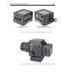
Attaching the Leaf Digital Camera Back to the Camera Body
1. Mount the Mamiya RZ67, Mamiya RZ67 Pro II, or Mamiya RZ67 Pro
IID camera on a tripod.
2. Insert the four studs on the Mamiya camera body into the four holes
on the adaptor.
Figure 52: Connecting the Leaf AptusII digital camera back
3. Secure the adaptor plate to the camera body by flipping the locking
lever from right to left into the locked position.
4. Remove the protective cover from Leaf AptusII.
5. Connect the digital camera back to the camera body. Rest the digital
camera back on the lower supports making sure that the lugs are
properly engaged in the recesses.
6. Move the camera back toward the camera body and check that the
camera’s upper support hooks fit into the slots on the camera back,
and lock it into place.
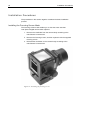
7. Lock the digital camera back into place.
Multiple Revolving lever
Figure 53: Locking the Leaf AptusII digital camera back into position
Note: Make sure the Multiple/Revolving lever is set to M.
56
Installation Procedures
To change the orientation of Leaf AptusII:
1. Switch the Multiple/Revolving lever on the side of the Mamiya RZ67
camera to R position.
2. To switch from landscape to portrait orientation, gently rotate the
digital camera back 90° clockwise until it snaps into place.
Connecting the Cables
This section contains procedures for connecting various cables for use with
the Mamiya RZ67 camera.
Connecting the Camera Control Cable
Note: Make sure the lever on the Camera Control cable is in O position.
1. Insert one end of the Camera Control cable (lever facing down) into
the Mamiya release socket on the front of the camera.
2. Turn the lever to the L position to lock it.
3. Insert the opposite end of the cable into the Camera Control socket
on Leaf AptusII.
Figure 54: Connecting the Camera Control Cable to Leaf AptusII
Connecting the Camera-to-Back Sync Cable
1. Insert one end of the Camera-to-Back Sync cable into the Mamiya
Lens Flash socket.
2. Insert the other end of the cable into the Camera.
Mamiya RZ67/RZ67ProII/ RZ67ProIID
57
Figure 55: Connecting a Camera-to-Back Sync cable to Leaf AptusII
Connecting the Flash Sync Cable
Note: The Leaf AptusII digital camera back together with the Flash Sync cable
is only suitable for use with external flash or strobe lighting.
Connect the flash sync cable to the Flash Sync connector on Leaf AptusII.
Figure 56: Connecting a Flash Sync Cable to Leaf AptusII
Connecting the FireWire Cable
For information about connecting the FireWire cable, see Working in
Tethered Mode, page 65.
58
Installation Procedures
Removing the Leaf Digital Camera Back From the Camera Body
1. Place the camera on a steady, flat surface.
2. If any of the following cables are connected, disconnect them:
•
FireWire cable
•
Camera Control cable
•
Camera-to-Back Sync cable
•
Flash Sync cable
3. Slide and push the Release button.
Release Button
Figure 57: Removing the Leaf AptusII digital camera back from Mamiya 645 AF-D
camera.
4. Tilt the camera back away from the camera body to remove it.
6
Large Format
BEFORE GETTING STARTED...........................................................................................60
ITEMS REQUIRED FOR THE INSTALLATION ....................................................................60
QUICK INSTALLATION REFERENCE ...............................................................................61
T HE D IGITAL CAMERA BACK ON A LARGE FORMAT CAMERA WITH A ROLLEI
ELECTRONIC SHUTTER ...................................................................................................61
T HE D IGITAL CAMERA BACK ON A LARGE FORMAT CAMERA WITH A SCHNEIDER
ELECTRONIC SHUTTER ...................................................................................................63
USING A MECHANICAL SHUTTER LENS ........................................................................63
60
Before Getting Started
Before Getting Started
This chapter describes the Leaf AptusII digital camera back installation for
large format cameras and other view cameras.
With the Rollei or Schneider electronic shutter and the Rollei Lens Control or
Schneider Shutter Control unit, the Leaf Capture application enables you to
change shutter speed and lens aperture on the large format camera from the
application.
The Leaf AptusII digital camera back can also be used with a mechanical
shutter lens such as the Copal shutter.
Items Required for the Installation
For a detailed list of the items required for installation, see Items Required
for the Installation, page 4.
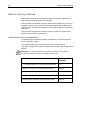
The following table shows the extra items that are required for the
/HDIAptusII digital camera back installation when working with a large format
camera
Important: To avoid installation and operation problems, use only the
accessories supplied with the Leaf digital camera back.
Items
Required for Basic
Installation
4” x 5” Graflok adaptor or other large format adaptor
Yes
Rollei Lens Control or Schneider Shutter Control
Optional
Lens Control power interface
Optional
Rollei-Aptus II Lens Control interface cable
Optional
Schneider-Aptus II Shutter Control interface cable
Optional
Large Format
61
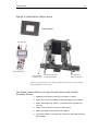
Quick Installation Reference
Graflok adaptor
A
B
C
Rollei Lens Control
A
Lens Control to
Camera Control
C
B
Camera to Back Sync
to Lens Control Sync
Lens Control to
Electronic Shutter
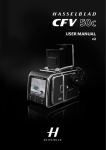
Figure 58: Connecting the Leaf AptusII digital camera back to a large format
camera and Rollei Lens Control
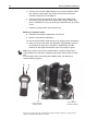
The Digital Camera Back on a Large Format Camera with a Rollei
Electronic Shutter
1. Make sure the camera is securely mounted on a tripod.
2. Attach the lens with the Rollei shutter to the large format camera.
3. Attach the adaptor e.g. Graflok, to the back of the camera and
secure it.
4. Remove the protective cover from Leaf AptusII.
5. Attach the digital camera back to the adaptor.
6. Connect the cable of the Rollei Lens Control to the Rollei electronic
shutter cable.
62
Quick Installation Reference
5. Connect one end of the Rollei-Aptus II Lens Control interface cable
to the B port of the Rollei Lens Control and the other end to the
Camera Control jack of Leaf AptusII.
6. Insert one end of the Camera-to-Sync cable into the Rollei Lens
Control Sync jack and the other end into the Camera-to-Back Sync
jack on Leaf AptusII. If you are working in tethered mode, go to step
8 now.
7. Install the compact flash card and power up.
Working in tethered mode:
8. Install the Leaf Capture application from the CD.
9. Start the Leaf Capture application.
10. Connect the FireWire cable between the computer and Leaf AptusII.
11. After you connect the cable, the application automatically connects
to Leaf AptusII. When the connection is established, the LED
indicator on the digital camera back turns from orange to green.
Note: If you want to work with an external flash, connect the Flash Sync
cable between the Leaf AptusII digital camera back and the flash or strobe
unit.
For information about connecting the FireWire cable, see Working in
Tethered Mode, page 65.
A
C
A
Lens Control to
Camera Control
C
Lens Control to
Electronic Shutter
Figure 59: Connecting the Leaf AptusII digital camera back to a large format
camera and Schneider Shutter Control
Large Format
63
The Digital Camera Back on a Large Format Camera with a Schneider
Electronic Shutter
1. Make sure the camera is securely mounted on a tripod.
2. Attach the lens with the Schneider shutter to the large format
camera.
3. Attach the adaptor (e.g. Graflok ) to the back of the camera and
secure it.
4. Remove the protective cover from Leaf AptusII.
5. Attach the digital camera back to the adaptor.
6. Connect the cable of the Schneider Shutter Control to the Schneider
electronic shutter cable.
7. Connect the single end of the Schneider-Aptus II Lens Control
interface cable to the port of the Lens Control and attach the two
other ends to the Camera Control and Sync ports of Leaf AptusII.
8.
If you are working in tethered mode, go to step 10 now.
9. Install the compact flash card and power up the back and the Lens
Control.
Working in tethered mode:
10. Install the Leaf Capture application from the CD.
11. Start the Leaf Capture application.
12. Connect the FireWire cable between the computer and Leaf AptusII.
13. After you connect the cable, the application automatically connects
to Leaf AptusII. When the connection is established, the LED
indicator on the digital camera back turns from orange to green.
14. After you connect the cable, the application automatically connects
to Leaf AptusII. When the connection is established, the LED
indicator on the digital camera back turns from orange to green.
Notes: If you want to work with an external flash, connect the Flash Sync
cable between the Leaf AptusII digital camera back and the flash or strobe
unit.
For information about connecting the FireWire cable, see Working in
Tethered Mode, page 65.
Using a Mechanical Shutter Lens
1. Make sure the camera is securely mounted on a tripod.
2. Attach the mechanical shutter lens to the large format camera.
3. Attach the Graflok adaptor to the back of the camera and secure it.
4. Remove the protective cover from Leaf AptusII.
5. Attach the digital camera back to the Graflok adaptor.
64
Quick Installation Reference
6. Insert one end of the Camera-to-Sync cable into the mechanical
shutter lens and the other end into the Camera-to-Back Sync socket
of Leaf AptusII. If you are working in tethered mode, go to step 8
now.
7. Install the compact flash card. The installation is complete.
Working in tethered mode:
8. Install the Leaf Capture application from the CD.
9. Start the Leaf Capture application.
10. Connect the FireWire cable between the computer and Leaf AptusII.
11. The application automatically connects to Leaf AptusII. When the
connection is established, the LED indicator on the digital camera
back turns from orange to green.
Note: If you want to work with an external flash, connect the Flash Sync
cable between the Leaf AptusII digital camera back and the Flash/Strobe
units.
Figure 60: Large format cable with a mechanical shutter lens
8
Working in Tethered Mode
CONNECTING THE F IREW IRE CABLE............................................................................70
ATTACHING THE REPEATER...........................................................................................71
70
Connecting the FireWire Cable
Connecting the FireWire Cable
Important: The information in this chapter is relevant to all cameras in this
installation guide. Follow the specific installation procedures for the camera
you are using. It is important that you connect the FireWire cable correctly in
order not to cause unnecessary damage.
Important: To avoid connection problems, use only the Leaf FireWire cable
and repeater supplied with Leaf AptusII.
The FireWire cable (IEEE 1394A) links the computer to Leaf AptusII. The
cable carries both communication signals and electrical power. The cable is
a hot-plug cable that can be connected or disconnected without turning the
computer off or quitting the application.
1. Connect one end of the FireWire cable to the port at the bottom of
/HDIAptusII. Make sure that the FireWire cable connector is aligned to the
left of Leaf AptusII.
Figure 61: Connecting the FireWire cable to the Leaf AptusII digital camera back
2. Connect the other end of the cable to the port on the computer.
Tip: When you connect the FireWire cable after you start the Leaf Capture
application, the application automatically connects to the Leaf AptusII digital
camera back and recognizes the connected camera type.
Working in Tethered Mode
71
Attaching the Repeater
Note: Attaching the repeater is optional.
Note: If you want to extend the FireWire cable from 4.5m / 15 ft. to 9m / 30
ft., you can purchase the Leaf Repeater and Cable Kit.
1. Connect one of the FireWire cables from the computer to the single-side
connection of the repeater.
2. Connect the other FireWire cable from the digital camera back to one of
the ports on the double-side connection of the repeater.
Figure 62: Attaching the repeater
Note: To comply with the CE/FCC standard regulations, it is recommended
to use the FireWire cables that are supplied by Leaf.
9
Caring for the IR Filter Glass
IMPORTANCE OF THE PROTECTIVE IR FILTER GLASS ..................................................74
CLEANING THE PROTECTIVE IR FILTER GLASS...........................................................75
74
Importance of the Protective IR Filter Glass
Importance of the Protective IR Filter Glass
The Leaf AptusII digital camera back has a protective IR filter glass over the
sensor. The sensor is the most important and expensive part of your
/HDIAptusII. It is the component that converts the photographic image viewed by
the camera into an electronic signal which can be processed by the
Macintosh computer.
Figure 63: Protective IR filter glass on the underside of the Leaf AptusII digital
camera back
Warning!
The sensor is extremely sensitive to ESD (Electro Static Discharge) and can
be damaged by it.
During some stages of the installation process, the protective IR filter glass
is exposed to the environment. Do not touch the IR filter glass. Any
contamination of the IR filter glass (such as dust or fingerprints) will appear
in images that you capture.
Caring for the IR Filter Glass
75
Cleaning the Protective IR Filter Glass
1. Remove any condensation that may be inside the ionized nitrogen
sprayer nozzle.
2. Spray the protective IR filter glass with ionized nitrogen to remove large
dust particles.
3.
Fold a cleaning wipe to fit the width of the protective IR filter glass (see
image sequence). Hold the wipe with tweezers.
1
2
3
4
Figure 64: Preparing a cleaning wipe for soaking
4. Soak the cleaning wipe in isopropyl alcohol, making sure it is sufficiently
damp but not dripping.
Warning! Do not touch any part of the cleaning wipe that will come in
contact with the protective IR filter glass.
Warning! Do not use a dry cleaning wipe. It can cause ESD damage to the
sensor.
5. Clean the protective IR filter with the cleaning wipe, using a single
motion from right to left.
Figure 65: Cleaning the protective IR filter glass
6. If necessary, repeat the cleaning procedure until the protective IR filter
glass is clean.
76
Importance of the Protective IR Filter Glass
Important!
•
Never use the dry cloth for cleaning.
•
Never clean the protective IR filter glass with the window or lens
cleaner.
The residues from these products may permanently cloud the glass
plate.
•
Never spray compressed air directly on the digital camera back.
•
Do not reuse cleaning wipes.
•
Put the protective cover over the sensor plate whenever the digital
camera back is not attached to the camera.
•
To prevent contamination of the sensor, do not remove the
protective IR filter glass.
•
The protective IR filter can be replaced only by Leaf dealers or by
the Leaf Service Center.
Note: Cleaning wipes and cleaning fluid are supplied with the Leaf AptusII
digital camera back. You can order additional wipes from your local Leaf
dealer.