1
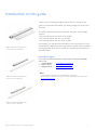
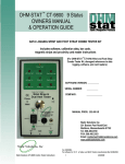
Design-in guide Philips Fortimo LED Line Systems – HV March 2013 Contents Contents 1 Installation instructions 31 Introduction to this guide 2 Information or support 2 Warnings and instructions 3 Introduction to the Fortimo LED Line System 4 Electrostatic discharge (ESD) Wiring Inserting and removing the cable connectors Strain relief Parasitic Current Protector 31 32 33 33 34 LED Line Cover 2ft soft-diffuse 36 Suitability Mechanical Lighting characteristics Lifetime of LED Lines in combination with the diffuser 36 36 37 37 Applications and luminaire classification 4 Commercial naming of the Fortimo LED Line, module and cable 4 Fortimo LED Line system configurations 6 Fortimo LED Line 2R availability per region Fortimo LED Line 1R availability per region Xitanium driver operating windows Philips LED Line cables Data for specific cable developed by OEM System configurations with LED Line 1ft 650 lm 3R HV1 System configurations with LED Line 1ft 1100 lm 3R HV1 System configurations with LED Line 2ft 1250 lm 2R HV1 System configurations with LED Line 2ft 2200 lm 1R HV1 Currents Specifications Configuration examples LED Line 3R Configuration example LED Line 1R Configuration example LED Line 2R 6 6 7 7 8 9 9 9 10 10 10 11 11 11 Mechanical characteristics 12 About the Philips Fortimo LED Line Tc point Mechanical fixation for LED Line 3R, 2R and 1R. Dimensions of LED Line 1ft 3R (mm) Dimensions of LED Line 2ft 1R (mm) Dimensions of LED Line 2ft 2R (mm) Dimensions of Xitanium indoor linear LED driver 12 13 13 14 14 15 15 Lighting characteristics 16 Beam shape High-quality light Color consistency (SDCM) Binning Future-proof design Optics Reflector design 16 16 16 18 19 20 21 Thermal management 23 Temperature and lifetime of the Fortimo LED Line Lumen maintenance of the Fortimo LED Line Operating windows * Graphical examples Cooling via the luminaire Thermal contact Recommendations Xitanium driver temperature 23 23 25 26 29 29 29 30 Design-in guide Philips Fortimo LED Line High Voltage System Installation instructions LED Line Cover 2ft softdiffuse 38 Warnings Important Mechanical requirements of luminaire Cleaning Installation possibilities In the box Step by step instructions 38 38 39 39 39 39 40 Controllability 44 Dimming Stand-alone Philips systems 44 44 Compliance and approval 45 Chemical compatibility 45 Compliance and approval marks 45 IP rating, humidity and condensation 45 Photobiological safety 45 Electromagnetic compatibility 46 System disposal 46 Safety 46 Electromagnetic compatibility (tested with LED Lines, cables and Philips Xitanium driver) 46 Environmental reliability tests 47 Mechanical reliability tests 47 Cautions on use during storage, transportation and operation 47 Contact details 48 Philips Fortimo LED Line Systems Partner for cables Philips ESD support ESD-related material and tool suppliers 48 48 48 48 1 Introduction to this guide Thank you for choosing the Philips Fortimo LED Line System. In this guide you will find the information you need to design this system into a luminaire. Philips Fortimo LED Line System 1ft 3R (1 foot, three rows of LEDs (3R)) This edition describes the Fortimo LED line 200-240 V mains voltage versions: - LED Line 1ft version with three rows of LEDs - LED Line 2ft version with one row of LEDs. - LED Line 2ft version with two rows of LEDs. In this edition you will also find information on the new LED Line Cover 2ft soft-diffuse. Extensions to the range will be included in future updates of this guide. We advise you to consult our websites for the latest up-todate information. Information or support If you require any further information or support please consult your local Philips office or visit: Fortimo LED Line www.philips.com/technology Xitanium drivers www.philips.com/xitanium OEM general info www.philips.com/technology Philips Fortimo LED Line System 2ft 1R (2 foot, one row of LEDs (1R)) - Notes: A separate design-in guide will be made available for the 120 V market. LED technology is continuously improving. For the latest updated information, please check www.philips.com/technology Philips Fortimo LED Line System 2ft 2R (2 foot, two rows of LEDs (2R)) Design-in guide Philips Fortimo LED Line High Voltage System 2 Warnings and instructions Warnings Avoid touching live parts! Do not use damaged LED Lines! Luminaires must be connected to protective earth. Safety warnings and instructions to be taken into account when the Fortimo LED Line System is designed into luminaires and during manufacture. Design-in phase It is mandatory to design the luminaire in such a way that it can only be opened with special tools (by a qualified electrician) in order to prevent touching of live parts (e.g. LED Line with a voltage potential of 230 V AC). Safety and IEC recommendations: The general IEC recommendations for luminaire design and national safety regulations (ENEC, CE, ANSI, etc.) are also applicable to selected Philips Fortimo LED Line Systems. Luminaire manufacturers are advised to conform to the international standards for luminaire design (Class I, IEC 60598-Luminaires). The luminaire must provide a protective earth. The installer must also connect the luminaire to protective earth! The luminaire must be constructed in such a way that the LED Line (or OEM integrated reflector) cannot be touched by an end-user. Do not connect a reflector to the LED Line without a proper earth connection. Do not apply mains power to the LED Line directly. Connect all electrical components first before switching on mains. Design-in and manufacturing phase Do not use damaged or defective contacts or housings. Do not drop the LED Line or let any object fall onto the LED Line because this may damage the PCB or LEDs. If the LED Line has been dropped or an object has fallen onto the LED Line, do not use it, even if there are no visible defects or signs of damage. Do not use damaged products. There are also LED Lines available for isolated drivers. The voltages of these types are different and they must not be interchanged with the version described in this document. Connect all electrical components first before switching on mains. Installation and service phase for luminaires incorporating the Fortimo LED Line System Do not service the luminaire when the mains voltage is connected; this includes connecting or disconnecting the LED Line cable. The installer must connect a luminaire incorporating the Fortimo LED Line System to protective earth! Do not use damaged products. Design-in guide Philips Fortimo LED Line High Voltage System 3 Introduction to the Fortimo LED Line System Applications and luminaire classification The Philips Fortimo LED Line System is the replacement for linear fluorescent lamps in general lighting. The system features a high level of energy efficiency, which surpasses T5 systems, at the lowest possible cost. It offers high-quality white light with excellent color rendering and color consistency and, as part of the Fortimo future-proof promise, it comes with a 5-year Philips guarantee. Philips Fortimo LED Line 3R The Fortimo LED Line System consists of a range of linear LED Lines (boards), Xitanium drivers and a variety of cables. The LED Line with three rows of LEDs, referred to as 3R, and LED Line with 2 rows of LEDs, referred to as 2R, are ideal for designing luminaires for diffuse applications. The LED Line with 1 row of LEDs, is applicable for luminaires requiring tighter beams for vertical lighting as well as luminaires for diffuse light if optics are applied. Both ranges feature a variety of different lengths, lumen packages and color temperatures. In this guide you will find the specific information required to develop a luminaire based on Philips Fortimo LED Line system. The Philips Fortimo LED Line System contains high-voltage solutions that comply with European Class I requirements for indoor lighting applications. Other applications or luminaires can be explored by OEMs as long as this does not create a design conflict. European luminaire standards, like IEC/EN 60598, must be complied with. In this guide you will find the specific information required to develop a luminaire based on the high voltage versions of Philips Fortimo LED Line 3R systems, Fortimo LED Line 2R systems and Fortimo LED Line 1R systems. Furthermore a special chapter on the use of the LED Line Cover 2ft soft-diffuse is written. Philips Fortimo LED Line 2R Can the LED Line be used in outdoor luminaires? Neither the Fortimo LED Line nor the driver have an IP classification > IP20. If you decide to use these products in a luminaire for outdoor applications the OEM will be responsible for ensuring proper IP protection and approbation of the luminaire. Please consult Philips if you wish to deviate from the design rules described in this guide (see last page for contact details). Commercial naming of the Fortimo LED Line, module and cable The names of the Fortimo LED Lines are defined as shown in underneath example: Fortimo LED Line 1ft 650lm 840 3R HV1 Fortimo : our concept name for efficient, clear and reliable lighting Philips Fortimo LED Line 1R LED Line : : the light source used linear board 1ft 650 lm 840 : : : length of LED Line 650 lumen output 8 denotes a color rendering index of 80 (CRI divided by 10) 3R : 40 stands for a CCT of 4000 K (CCT divided by 100) indicates the number of LED rows on a LED Line, in this case 3 HV : 1 Design-in guide Philips Fortimo LED Line High Voltage System High Voltage: indication of compliance with European class I requirements Generation 1 4 Philips Xitanium 75 W TD driver LED Line Cable 600 mm 432 r 1C HV NTC* Fortimo : our concept name for efficient, clear and reliable lighting LED : the light source used Line : linear board Cable : 600 mm : length of cable 432r : value of the resistor to set the current of the driver 1C : for number of electrical chains of LED lines HV : High Voltage NTC : Negative Temperature Coefficient connector included (only applicable for LED Line 1R and 2R) Fortimo LED Line cable 600 mm 1C Design-in guide Philips Fortimo LED Line High Voltage System 5 Fortimo LED Line system configurations In this section you will find all of the product information needed to make a configuration based on the Fortimo LED Line 1R, 2R and 3R system. These systems consist of the following products: Fortimo LED Line 3R availability per region Asia Pacific region Europe Middle East Africa Fortimo LED Line 1ft 650lm 830 3R HV1 ● ● Fortimo LED Line 1ft 650lm 840 3R HV1 ● ● Fortimo LED Line 1ft 650lm 850 3R HV1 ● Fortimo LED Line 1ft 1100lm 830 3R HV1 ● ● Fortimo LED Line 1ft 1100lm 840 3R HV1 ● ● Fortimo LED Line 1ft 1100lm 850 3R HV1 ● Fortimo LED Line 2R availability per region Asia Pacific region Europe Middle East Africa Fortimo LED Line 2ft 1250lm 830 2R HV1 ● Fortimo LED Line 2ft 1250lm 840 2R HV1 ● Fortimo LED Line 1R availability per region Asia Pacific region Europe Middle East Africa Fortimo LED Line 2ft 2200lm 830 1R HV1 ● ● Fortimo LED Line 2ft 2200lm 840 1R HV1 ● ● Fortimo LED Line 2ft 2200lm 850 1R HV1 ● A selection of the Philips Xitanium drivers available Xitanium LED driver 75 W 0.15-0.4A 200V TD 230V (Touch and DALI) Xitanium LED driver 75 W 0.2-0.4A 200V 1-10V 230V (1-10 V) Xitanium LED driver 75 W 0.15-0.4A 200V 230V (fixed output) Xitanium LED driver 36 W 0.12-0.4A 100V TD 230V (Touch and DALI) Xitanium LED driver 36 W 0.12-0.4A 100V 1-10V 230V (1-10 V) Xitanium LED driver 36 W 0.12-0.4A 100V 230V (fixed output) Xitanium LED driver 17 W 0.12-0.4A 54V TD 230V (Touch and DALI) Xitanium LED driver 17 W 0.12-0.4A 54V 1-10V 230V (1-10 V) Philips LED Line cables Cables to connect the driver to the LED Line Cables to interconnect one LED Line to another A return-end cable to close the circuit If necessary you can develop your own LED cable. See details in the following section entitled 'Information on specific cables developed by OEMs‟. Design-in guide Philips Fortimo LED Line High Voltage System 6 Xitanium driver operating windows The Xitanium drivers have a voltage and a current range, known as the 'operating window'. This means that multiple combinations of LED Lines and drivers are possible. The graph shows the operating windows of the Xitanium drivers. The driver supplies a constant current to drive the LED Line. The correct current setting can be chosen in three ways. If no resistance value is connected, this automatically results in a 400 mA output current of the Xitanium driver. 1. 2. 3. The output current of the driver can be set by connecting a specific resistor value to the driver. Philips supplies driver-to-board cables with integrated resistors (Rset). The OEM uses its own design of connector cables. The Xitanium Touch/DALI TD drivers can be programmed in order to set the desired current. Philips LED Line cables There are several cables available to suit your luminaire design. Cables to connect the driver to the LED Lines without a resistor The LED Line cables are designed to connect the Xitanium drivers to the LED Lines 1R, 2R and 3R. The length of this cable is 600 mm. If required, it can also incorporate a resistor (Rset) that defines the output current of the driver. The cables without Rset resistor are used if the Late Stage Configuration function of the driver is used. Driver to LED Line cable 1C (for one chain of LEDs) Driver to LED Line cable 2C (for two chains of LEDs) Cables with and without Rset are available in 1-chain (1C) or 2-chain (2C) versions, depending on the amount of modules you wish to connect to the driver. The cables consist of a 7-pin connector on the driver side, and one or two 2-pin connectors to connect the modules. Chains of LED Lines Cable length A 12 NC LED Line cable 600 mm 1C HV 1 (1C) 600 mm 9290 006 90503 LED Line cable 600 mm 2C HV 2 (2C) 600 mm 9290 006 90403 Cables to connect the driver to the LED Line with a resistor Driver to LED Line cable 1C with resistor (for one chain of LEDs) Driver to LED Line cable 2C with resistor (for two chains of LEDs) Design-in guide Philips Fortimo LED Line High Voltage System Rset Ω Chains of LED Lines Cable length A 12 NC LED Line cable 600 mm 232r 1C HV 232 1 (1C) 6 0 mm 9290 006 97803 LED Line cable 600 mm 619r 2C HV 619 2 (2C) 600 mm 9290 006 97703 LED Line cable 600 mm 464r 1C HV 464 1 (1C) 600 mm 9290 006 96003 LED Line cable 600mm 432r 1C HV NTC* 432 1 (1C) 600 mm 9290 006 79903 LED Line cable 600mm 590r 1C HV NTC* 590 1 (1C) 600 mm 9290 008 04903 This cable includes an extra connector to be used for the Negative Temperature Coefficient (NTC) resistor signal. 7 Cables to connect a LED Line to another LED Line Cables are available in a variety of lengths to connect the LED Lines 3R with each other (Board to Board (B2B)). Cable length A 12 NC LED Line cable 46 mm B2B 46 mm 9290 006 81603 LED Line cable 115 mm B2B 115 mm 9290 006 81703 LED Line cable 190 mm B2B 190 mm 9290 006 81803 LED Line interconnecting cable Return-end cable A „return-end‟ cable must be attached at the end of every chain of LED Lines to close the circuit. LED Line return cable Return cable Cable length A 12 NC LED Line return-end cable HV 20 mm 9290 006 81503 Data for specific cable developed by OEM We advise using the Fortimo LED Line cables. Approval of the LED Line and Xitanium LED driver is based on a reference luminaire with the standard Philips cable of 60 cm. Any luminaire design needs its own approval, organized by the responsible OEM, irrespective of the length of cable used. If you prefer to develop a cable with a different length, the specification should meet IEC/EN requirements. When selecting wiring, it must be borne in mind that the cable must not emit hazardous gases or catch fire when exposed to high temperatures (e.g. PVC-free) The following cable/connector specifications can be used: JST connector for cable to Xitanium 75 W LED driver: housing JST PAP-07V-S contact JST SPHD-001T-P0.5 diameter of the cable: 24AWG Molex connector for the module: crimp housing Molex 503473-0290 crimp terminal Molex 503485-0100 Contact 1 = IDC Contact 2 = NC Contact 3 = PGND Contact 4 = NTC Contact 5 = ISET1 Contact 6 = ISET2 Contact 7 = SGND Design-in guide Philips Fortimo LED Line High Voltage System white wire, connected to the “+” anode. not connected yellow wire, connected to the “-“cathode. optional to connect to the NTC on the LED board, if available or to use MTP optional to set current via Iset1, available on specific drivers optional to set current via Iset2, available on specific drivers Signal Ground for connections to pin 4, 5 and 6 8 System configurations with LED Line 1ft 650 lm 3R HV1 The following configurations can be assembled for the LED Line 1ft 650lm 3R HV1. The resistor values are chosen in such a way that the nominal flux of 650 lm per LED Line is obtained (4000 K). Number of Fortimo LED Line 1ft 650lm 3R HV1 Driver Cable 1 Xitanium 17 W LED Line cable 600 mm 232r 1C HV 2 Xitanium 17 W LED Line cable 600 mm 619r 2C HV 3 Xitanium 36 W LED Line cable 600 mm 232r 1C HV 4 Xitanium 36 W LED Line cable 600 mm 619r 2C HV 5* Xitanium 75 W LED Line cable 600 mm 232r 1C HV 6 Xitanium 36 W LED Line cable 600 mm 619r 2C HV 6* Xitanium 75 W LED Line cable 600 mm 232r 1C HV 8 Xitanium 75 W LED Line cable 600 mm 619r 2C HV 10 Xitanium 75 W LED Line cable 600 mm 619r 2C HV 12 Xitanium 75 W LED Line cable 600 mm 619r 2C HV * Not possible with 75 W 0.2-0.4 A 200V 1-10V 230V System configurations with LED Line 1ft 1100 lm 3R HV1 For LED Line 1ft 1100 lm 3R HV1 the resistor values are chosen to obtain a nominal flux of 1100 lm per LED Line (4000 K). Number of Fortimo LED Line 1ft 1100lm 3R HV1 Driver Cable 1 Xitanium 17 W LED Line cable 600 mm 464r 1C HV 2 Xitanium 36 W LED Line cable 600 mm 464r 1C HV 3 Xitanium 36 W LED Line cable 600 mm 464r 1C HV 4 Xitanium 75 W LED Line cable 600 mm 464r 1C HV 5 Xitanium 75 W LED Line cable 600 mm 464r 1C HV 6 Xitanium 75 W LED Line cable 600 mm 464r 1C HV System configurations with LED Line 2ft 1250 lm 2R HV1 For LED Line 2ft 1250 lm 2R HV1 the resistor values are chosen to obtain a nominal flux of 1250 lm per LED Line (4000 K). Design-in guide Philips Fortimo LED Line High Voltage System Number of Fortimo LED Line 2ft 1250lm 2R HV1 Driver Cable 1 Xitanium 17 W LED Line cable 600 mm 590r 1C HV NTC 2 Xitanium 36 W LED Line cable 600 mm 590r 1C HV NTC 3 Xitanium 36 W LED Line cable 600 mm 590r 1C HV NTC 4 Xitanium 75 W LED Line cable 600 mm 590r 1C HV NTC 5 Xitanium 75 W LED Line cable 600 mm 590r 1C HV NTC 6 Xitanium 75 W LED Line cable 600 mm 590r 1C HV NTC 9 System configurations with LED Line 2ft 2200 lm 1R HV1 For LED Line 2ft 2200 lm 1R HV1 the resistor values are chosen to obtain a nominal flux of 2200 lm per LED Line (4000 K). Number of Fortimo LED Line 2ft 2200lm 1R HV1 Driver Cable 1 Xitanium 36 W LED Line cable 600 mm 432r 1C HV NTC 2 Xitanium 75 W LED Line cable 600 mm 432r 1C HV NTC 3 Xitanium 75 W LED Line cable 600 mm 432r 1C HV NTC Warning In cases where the OEM chooses to set the current (either by programming or by applying a Rset resistor), the lifetime and reliability of the LED Line must be taken into account. The following current regions can be distinguished: 1. Current < nominal current a. Lifetime > 50,000 hours b. Efficiency higher than nominal value, lumen output lower than nominal value 2. Current between nominal current and max. current for lifetime a. Lifetime > 50,000 hours b. Efficiency lower than nominal value, lumen output higher than nominal value 3. Current between max. current for lifetime and absolute max. current. No warranty applicable in this case. a. Lifetime < 50,000 hours b. Efficiency lower than nominal value, lumen output higher than nominal value 4. Current > absolute maximum current: do not exceed the absolute maximum current as this can lead to LED line failure. No warranty applicable in this case. Currents Fortimo LED Line I nominal* mA I life** mA I max*** mA LED Line 1ft 650 lm 3R HV1 160 185 225 LED Line 1ft 1100 lm 3R HV1 260 400 400 LED Line 2ft 2200 lm 1R HV1 280 280 400 LED Line 2ft 1250 lm 2R HV1 306 370 400 * Nominal current at which performance is specified ** Current at which lifetime is specified *** Maximum current for safety The rated average life is based on engineering data testing and probability analysis. The hours are at the L70 B50 point. Specifications The latest up-to-date detailed specifications can be found at www.philips.com/technology Design-in guide Philips Fortimo LED Line High Voltage System 10 Configuration examples LED Line 3R The drawings below show both 1-chain (1C) configuration and a 2-chain (2C) configurations. All the different cables with connector types are included (driver-toboard, board-to-board and return-end). One-chain configuration Two-chain configuration Two-chain configuration with 8x Fortimo LED Lines Configuration example LED Line 1R One-chain configuration with Fortimo LED Line Configuration example LED Line 2R One-chain configuration with Fortimo LED Line. Design-in guide Philips Fortimo LED Line High Voltage System 11 Mechanical characteristics About the Philips Fortimo LED Line The LED Line consists of a PCB assembly with components: LEDs Connectors (to connect another LED Line or Xitanium driver). Please note that LED Line 1R can be connected to another 1R but not to 3R nor to 2R. Same is valid for LED line 3R which can be connected only to another 3R and likewise LED line 2R can only be connected to another 2R. The LED Line consists of a carrier with current-conducting copper tracks, which also acts as a heat spreader. The heat spreader facilitates optimum transfer of heat to the air. The PCBA has 4 screw holes for fixing it to the mounting plate with M4 screws. No specific heat sinks are needed (see section entitled „Thermal management‟). The applied LEDs contain a zener diode that protects against electrostatic discharge (ESD). Fortimo LED Line 3R layout Fortimo LED Line 1R layout Fortimo LED Line 2R layout Design-in guide Philips Fortimo LED Line High Voltage System 12 Tc point The Tc test point indicates a reference point for measuring the LED Line temperature with a thermocouple glued to the PCB surface. This can be used during the luminaire design to verify that the temperature remains below the maximum specified temperature for the Tc test point. Tc point LED Line 3R The LED Line 1R and 2R comprises an on-module NTC. With the LED line cable 600 with NTC connector you can connect the designated Xitanium driver. The NTC can then be used for thermal protection of the LED line. When the threshold value is exceeded the output power will be automatically tuned down. This is done to keep the lifetime as specified. The threshold is fixed and cannot be changed. When designing and installing the luminaire according to this design in guide, the threshold value will not be exceeded. Mechanical fixation for LED Line 3R, 2R and 1R. Screws The Philips Fortimo LED Line 3R has four holes for fixing the LED Line to the luminaire. Each LED Line has four holes for M4 (or size 8) screws. To ensure optimum thermal contact with the luminaire (and therefore optimum lifetime) we recommend all screw holes are used. To ensure the electrical isolation when using metal screws, the diameter of the screw head (and optional metal washer) must not exceed 8 mm. Tc point LED Line 2R The LED Line 2200lm 1R has six holes for mounting the module to a luminaire. There are also six holes available for mounting optics. The electrical isolation distance around these holes is not suitable for metal screws. When using these holes with metal screws, apply isolating washers. The LED Line 1250lm 2R has five holes for mounting the module to a luminaire. There are also two optional holes available for mounting. These holes can also be used for mounting optics. Tc point LED Line 1R Screw type and torque The maximum torque that should be applied depends on the screw type and luminaire material. The fasteners used to secure the LED Line to a heat sink must be tightened with a torque in accordance with the table below. Screw torque min max Steel or aluminum, threaded/taptite M4 0.6 nm 1.0 nm Optics Luminaire manufacturers have the freedom to design their own (secondary) optics. No primary optics have been added to the LED Line to ensure optimum lm/W efficiency of the system. Design-in guide Philips Fortimo LED Line High Voltage System 13 Dimensions of LED Line 1ft 3R (mm) Min Type Max Unit Length 279.8 280.0 280.2 mm Width 54.8 55.0 55.2 mm Height including connector 4.3 4.65 4.9 mm Min Type Max Unit Length 560.4 560.7 561.0 mm Width 39.8 40.0 40.2 mm Height including connector 4.3 4.65 5.0 mm Dimensions of LED Line 2ft 1R (mm) Design-in guide Philips Fortimo LED Line High Voltage System 14 Dimensions of LED Line 2ft 2R (mm) Min Type Max Unit Length 579.7 580.0 580.3 mm Width 36.5 36.7 36.9 mm Height including connector 4.3 4.65 5.0 mm Dimensions of Xitanium indoor linear LED driver For driver dimensions please check the respective datasheet on www.philips.com/technology. Design-in guide Philips Fortimo LED Line High Voltage System 15 Lighting characteristics Beam shape The Philips Fortimo LED Line generates a Lambertian beam shape, which is a pragmatic starting point for OEMs wishing to design secondary optics. High-quality light High-quality white light is characterized by a color rendering index (CRI) of 80. It is also important to apply widely favored CCTs (in general lighting applications: 3000 and 4000 K) and a color consistency comparable with conventional fluorescent lighting. The Fortimo LED Line 1R and 3R are available in 3000, 3500, 4000 and 5000 K. Polar diagram of Fortimo LED Line 1ft 650 lm 3R Color consistency (SDCM) The specification of our Fortimo LED Line 1R and 3R 3000, 3500, 4000 and 5000 K for color consistency is 3.5 SDCM at 0 hours. At 6,000 hours the color shift u‟v‟ is smaller than 0.007. SDCM stands for Standard Deviation of Color Matching and the value 3.5 refers to the size of an ellipse around the black body locus. Staying within this ellipse results in a consistency of light which ensures that no color difference is perceivable between one LED Line and another with the naked eye in most applications. Warning: the 3.5 SDCM color consistency specification may not be sufficient for applications that are sensitive to color differences like wall washers, which typically require 2 SDCM. Polar diagram of Fortimo LED Line 1ft 1100 lm 3R Polar diagram of Fortimo LED Line 2ft 2200 lm 1R Design-in guide Philips Fortimo LED Line High Voltage System The central CCT points are (measurement tolerance ±0.004): 3000 K 3070 K CIEx 0.4322 and CIEy 0.4024 3500 K 3490 K CIEx 0.4059 and CIEy 0.3908 4000 K 4020 K CIEx 0.3802 and CIEy 0.3786 5000 K 5090 K CIEx 0.3427 and CIEy 0.3523 Polar diagram of Fortimo LED Line 2ft 1250 lm 2R 16 Spectral light distribution Spectral light distribution Philips Fortimo LED Line 3000 K Spectral light distribution Philips Fortimo LED Line 3500 K Spectral light distribution Philips Fortimo LED Line 4000 K Spectral light distribution Philips Fortimo LED Line 5000 K Design-in guide Philips Fortimo LED Line High Voltage System 17 Binning Philips has created high-quality LED light by ensuring correct mixing of the LED bins within each LED Line. There is a limited need for binning of LED Lines in two bins only. N.B. Fortimo LED Lines are labeled and packaged in two voltage bins. For LED Line 1ft 650 lm 3R HV1, LED Line 1ft 1100 lm 3R HV1 and LED Line 2ft 1100lm 1R HV1 are divided into bins „A‟ and „C‟. In order to ensure optimum flux and color uniformity, we advise against mixing two different bins in the same luminaire. The Vf bin is clearly indicated on the label, as shown in the example below. All LED Lines packaged in one box will be from the same bin. Example label on LED Line indication bin A for example Why address the issue of LED binning? It is important to understand binning because it is very important in LED system design. As in other semiconductor manufacturing processes, in the production of LEDs the number of parameters of the epitaxy process is very large and the process window is small (for example, the temperature must be controlled to within 0.5 °C across the wafer at temperatures of ~800 °C). The fact that it is difficult to achieve such a high degree of control means that the properties of the LEDs may vary significantly within single production runs and even on the same wafer. To obtain consistency for a given application, binning (= selection in bins) is mandatory. Binning involves characterizing the LEDs on the basis of measurement and subsequently categorizing them into several specific bins. To keep the cost per LED down, LED manufacturers need to sell the full production distribution. At the same time they cannot guarantee the availability of all bins at all times. There is a trade-off between logistics and cost price on the one hand, and the application requirements on the other. The advantage of this is that there will only be a limited need for LED Line pairing by the OEM. Design-in guide Philips Fortimo LED Line High Voltage System 18 Future-proof design New-generation LEDs will become more efficient in the future, which will give us the opportunity to change the LEDs and/or the LED pitch of the LED Line. In order to prevent the need for a new luminaire design, and to keep the mechanical dimensions and the flux consistent (future-proof), we therefore also advise designing luminaire optics (reflector and diffuser) based on a LED pitch of 25 mm x- and ydirection. Future proof design with max. 25 mm LED pitch Examples show LED Line 3R, 2R and 1R Design-in guide Philips Fortimo LED Line High Voltage System 19 Optics Luminaire manufacturers have the freedom to design their own optics in order to maximize the lm/W efficiency of the system. If multiple LED Lines are installed, we recommend a distance of 6 mm (LED Line 1ft 3R) and 1.3 mm (LED Line 2ft 1R) is maintained between the LED Lines to ensure a continuous optical pitch. A continuous optical pitch with 6 mm distance between the LED Lines 1ft 3R Between LED Lines 2ft 2R a distance of 0.8 mm recommended for a continuous optical pitch Between LED Lines 2ft 1R a distance of 1.3 mm is recommended Design-in guide Philips Fortimo LED Line High Voltage System 20 Reflector design If a reflector is designed around the LED Line, it is essential to allow a clearance distance between the LED Line and reflector (2 mm) around the LED Line surface, LEDs and the connectors (see drawing below). This clearance distance is necessary to ensure safe isolation of the system and is in line with IEC regulations 60598 to prevent short circuiting, damage and an open circuit to the LED Line. Clearance distances required for optical design LED Line 1ft 3R Clearance distances required for optical design LED Line 1ft 1R Design-in guide Philips Fortimo LED Line High Voltage System 21 Clearance distances required for optical design LED Line 1ft 2R Warning The reflector must be connected to protective earth in order to prevent hazardous conditions! Design-in guide Philips Fortimo LED Line High Voltage System 22 Thermal management The critical thermal management points of the LED Line and driver are set out in this section to facilitate the design-in of Fortimo LED Line Systems. If these thermal points are taken into account this will ensure the optimum performance and lifetime of the system. Temperature and lifetime of the Fortimo LED Line The Tc rises as the ambient temperature increases. The temperature offset between Tambient and Tc depends on the thermal design of the luminaire. The Fortimo LED Line System has been designed for indoor use and ambient temperatures from 0 °C and higher. The Tc of the LED Line must be complied with at all times. For LEDs it is the junction temperature that is the critical factor for operation and lifetime. Since there is a direct relation between the case temperature and the LED junction temperature, it is sufficient to measure the case temperature at the Tc point on the upper side of the LED Line. This Tc point must not exceed the maximum values shown in the table below. This table also shows the Tc at which the performance specifications of the LED Line are valid. Fortimo LED Line Tc nominal * °C Tc life** °C Tc max*** °C LED Line 1ft 650 lm 3R HV1 35 56 70 LED Line 1ft 1100 lm 3R HV1 35 62 70 LED Line 2ft 2200 lm 1R HV1 35 58 70 LED Line 2ft 1250 lm 2R HV1 35 55 65 * ** *** Nominal Tc at which performance is specified Maximum Tc at which lifetime is specified Maximum Tc for safety Definitions The definitions used in this chapter are as follows: Driver temperature: temperature measured at the Tc point of the driver. Driver ambient temperature: temperature inside the luminaire around the driver. Luminaire ambient temperature: temperature outside the luminaire. Lumen maintenance of the Fortimo LED Line In case both the current and Tc are kept below the recommended values for 50,000 hours lifetime, the following lumen maintenance curves apply. The graphs below show the estimated lumen depreciation curves at Tc life and I life. Both B50 and B10 curves are shown, representing 50% and 90% of the population. These estimations are based on 9000 hours of LM80 testing and calculated according to the TM-21 guideline. After 50,000 hours the lines are dotted, because officially we cannot predict lumen maintenance beyond 50,000 hours. Lowering the drive current will increase the lumen maintenance time. The test results of the LEDs of the Fortimo LED Line 1ft 650lm 3R HV1 and Design-in guide Philips Fortimo LED Line High Voltage System 23 Fortimo LED Line 2ft 1250lm 2R HV1 show no lumen depreciation at all at 6000 hours of LM80 testing. These products are specified to reach B50L70, and we are confident, on the basis of the encouraging 6000-hour test results, that the lumen maintenance could be even better. Lumen maintenance Fortimo LED Line 2ft 2200lm 1R HV1 100% 0% B10 Ref: 18W T8 70% Lumen depreciation (%) Lumen maintenance (%) B50 Specification Min.B50L70 50,000 hours proven by certified laboratory The B10 and B50 graphs show expected lumen maintenance at current life and Tc life 0% 0 10,000 20,000 30,000 40,000 50,000 100% 60,000 Operating lifetime (hours) Lumen depreciation as a function of operating hours for LED Line 2ft 2200lm 1R HV1 Lumen maintenance Fortimo LED Line 1ft 1100lm 3R HV1 100% 0% B50 Lumen depreciation (%) Lumen maintenance (%) B10 Ref: 18W T8 70% Specification Min.B50L70 50,000 hours proven by certified laboratory The B10 and B50 graphs show expected lumen maintenance at current life and Tc life 0% 0 10,000 20,000 30,000 40,000 50,000 100% 60,000 Operating lifetime (hours) Lumen depreciation as a function of operating hours for LED Line 1ft 1100lm 3R HV1 Lumen maintenance is also affected by temperature. Lowering the Tc will increase the lumen maintenance time. The graph at the next page shows the lumen depreciation curves (B50) at I life for Tc nom, Tc life and Tc max. Lumen maintenance (B50) Fortimo LED Line 2ft 2200lm 1R HV1 100% 0% Tc nom 35 °C 70% Lumen depreciation (%) Lumen maintenance (%) Tc life 58 °C Tc max 70 °C Ref: 18W T8 Specification Min.B50L70 50,000 hours proven by certified laboratory The B50 graphs show expected lumen maintenance at Current life 0% 0 10,000 20,000 30,000 40,000 50,000 100% 60,000 Operating lifetime (hours) Lumen depreciation as a function of operating hours for LED Line 2ft 2200lm 1R HV1 at different Tc values Design-in guide Philips Fortimo LED Line High Voltage System 24 Lumen maintenance (B50) Fortimo LED Line 1ft 1100lm 3R HV1 100% 0% Tc nom 35 °C Lumen depreciation (%) Lumen maintenance (%) Tc life 62 °C Tc max 70 °C Ref: 18W T8 70% Specification Min.B50L70 50,000 hours proven by certified laboratory The B50 graphs show expected lumen maintenance at Current life 0% 0 10,000 20,000 30,000 40,000 100% 60,000 50,000 Operating lifetime (hours) Lumen depreciation as a function of operating hours for LED Line 1ft 1100lm 3R HV1 at different Tc values Note that the above graphs are lifetime predictions based on LM80 data; no guarantee outside specified lifetime specifications. Operating windows * Data for LED Line 1 ft 650lm 3R HV1 3000 K 3500 K 4000 K 5000 K Current mA flux lm efficiency lm/W flux lm efficiency lm/W flux lm efficiency lm/W flux lm efficiency lm/W 75 310 135 330 142 335 145 345 148 125 495 125 520 131 530 134 540 137 175 660 118 695 124 710 127 725 129 225 830 112 870 118 890 121 910 123 Data for LED Line 1 ft 1100lm 3R HV1 3000 K 3500 K 4000 K 5000 K Current mA flux lm efficiency lm/W flux lm efficiency lm/W flux lm efficiency lm/W flux lm efficiency lm/W 150 650 141 670 144 680 147 690 149 200 845 135 865 138 880 141 895 143 250 1030 130 1055 133 1075 136 1095 138 300 1215 126 1240 129 1265 131 1290 134 350 1395 122 1430 125 1455 128 1480 130 400 1570 119 1605 122 1635 124 1665 126 Data for LED Line 2 ft 2200lm 1R HV1 3000 K 3500 K 4000 K 5000 K Current mA flux lm efficiency lm/W flux lm efficiency lm/W flux lm efficiency lm/W flux lm efficiency lm/W 150 1230 131 1260 134 1285 136 1310 139 200 1590 124 1630 127 1660 130 1690 132 250 1940 119 1990 122 2025 124 2060 126 300 2280 114 2335 117 2380 119 2425 122 350 2620 110 2680 113 2730 115 2780 117 400 2945 107 3015 109 3070 111 3125 113 Design-in guide Philips Fortimo LED Line High Voltage System 25 Data for LED Line 2 ft 1250lm 2R HV1 3000 K 4000 K Current mA flux lm efficiency lm/W flux lm efficiency lm/W 150 630 134 675 144 200 815 129 875 138 250 990 124 1065 133 300 1165 120 1250 129 350 1335 117 1435 126 400 1505 114 1615 123 * Results are based on theoretical simulations with Philips LED modeling. Tolerances on LED Line efficacy are +/- 10% and flux +/- 7.5 %. Graphical examples 150 800 145 700 140 600 135 500 130 400 125 300 150 200 1400 145 1200 140 efficiency 1000 135 800 130 600 250 150 LED Line current (mA) 150 135 1000 130 800 125 600 120 250 300 350 400 LED Line current (mA) Design-in guide Philips Fortimo LED Line High Voltage System 450 luminous flux (lm) luminous flux (lm) 140 1200 efficiency (lm/W ) 145 1400 200 200 250 300 350 400 450 Fortimo LED Line 2ft 2200lm 840 1R HV1 1600 150 efficiency LED Line current (mA) Fortimo LED Line 2ft 1250lm 840 2R HV1 100 luminous flux 125 100 3500 150 3000 140 2500 130 luminous flux efficiency 2000 120 1500 110 1000 efficiency (lm/W ) 100 150 luminous flux 120 50 1600 efficiency (lm/W) 900 luminous flux (lm) Fortimo LED Line 1ft 1100lm 840 3R HV1 efficiency (lm/W) luminous flux (lm) Fortimo LED Line 1ft 650lm 840 3R HV1 luminous flux efficiency 100 100 150 200 250 300 350 400 450 LED Line current (mA) 26 How to measure the temperature of the LED Line The Tc values are specified at the Tc point, which is indicated on the LED Line. The temperature can be measured via thermocouples that are firmly glued to the upper surface of the LED Line. For LED Line 1R and 2R also the onboard NTC can be used for measurements during development. For all measurements the temperature must be stable before any reliable data can be obtained (between 0.5 and 3 hours). Tc point to measure the LED Line 1ft 3R temperature Tc point to measure the LED Line 2ft 2R temperature Tc point to measure the LED Line 2ft 1R temperature Red circle indicates where to place the NTC on the board Design-in guide Philips Fortimo LED Line High Voltage System Red circle indicates where to place the NTC on the board 27 The NTC is a resistor with a temperature dependent resistance value. The NTC resistance can be measured in two ways: 1. Directly on the NTC component (RNTC) 2. Using the onboard JST connector(RCONN) In the second method, the resistance of other resistors connected to the NTC is measured as well. The following table shows the relation between temperature and measured resistance for both methods. LED Line 2ft 1250lm 2R HV1 LED Line 2ft 2200lm 1R HV1 RNTC (Ohm) RCONN (Ohm) RNTC (Ohm) RCONN (Ohm) 0 49221 9656 49221 49611 5 38245 9147 38245 38635 10 29936 8584 29936 30326 15 23613 7981 23613 24003 20 18756 7351 18756 19146 25 15000 6710 15000 15390 30 12074 6073 12074 12464 35 9780 5455 9780 10170 40 7969 4867 7969 8359 45 6531 4320 6531 6921 50 5382 3819 5382 5772 55 4459 3366 4459 4849 60 3713 2962 3713 4103 65 3108 2605 3108 3498 70 2613 2292 2613 3003 75 2208 2019 - - 80 1873 1782 - - Temperature °C Relation between flux and Tc The flux of the LED Line is specified at a nominal Tc, which is a lower value than the maximum Tc corresponding to the lifetime specification. Increasing the temperature lowers the flux and lifetime of the LED Line. The relation between flux and Tc has been plotted in different graphs on the left and below LED Line 1ft 650 lm 3R luminous flux as a function of Tc Design-in guide Philips Fortimo LED Line High Voltage System LED Line 1ft 1100 lm 3R luminous flux as a function of Tc 28 LED Line 1ft 2200 lm 1R luminous flux as a function of Tc The unflatness of the area where the LED line is mounted should not exceed 1 mm along the LED Line LED Line 1ft 1250 lm 2R luminous flux as a function of Tc Cooling via the luminaire Thermal contact The unflatness of the area where the LED Line is mounted should not exceed 1 mm along the LED Line length in order to ensure good thermal contact and to avoid stress and strain on the LED Line. We also recommend that good-quality screws are used in order to ensure optimal contact between the bottom surface and the luminaire surface, without the need for thermal paste. Cooling surface area and material The amount of heat that needs to be transferred away from the LED Line to the ambient air is about 4 W for the LED Line 650 lm 3R, 6 W for the LED Line 1100 lm 3R and 13W for the LED Line 2200 lm 1R. This heat is dissipated via the luminaire housing. If the luminaire housing has sufficient thermal conductivity, the heat will spread further, thereby increasing the effective cooling area. We therefore recommend use of a material that has high thermal conductivity and is of sufficient thickness. This will lower the case temperature and enable the system to perform better (lifetime and light output). The required size of the luminaire housing area per LED Line depends on the design and volume of the luminaire, the thermal properties of the material used and the expected ambient temperature. Aluminum is usually preferable to steel because of its higher thermal conductivity, although for most applications steel is likely to be adequate for ambient temperatures of up to 35 °C. For higher ambient temperatures, the use of aluminum should be considered. Material k (W/mK) Copper 400 Aluminum 200 Brass 100 Steel 50 Corrosion-resistant steel 15 Thermal conductivity of different materials Recommendations General thermal design guidelines to improve the thermal management and performance of a luminaire: • • Design-in guide Philips Fortimo LED Line High Voltage System Simplify the heat path from Tc to cold ambient air. Use good thermally conductive materials in the primary heat path (e.g. aluminum). 29 • • • • Limit the number of thermal interfaces in the primary heat path towards the ambient air. Use thermal interface materials (TIM) to ensure proper thermal contact, i.e. between the LED Line and heat sink. Ensure proper heat spreading by using materials with good conductivity and/or materials of sufficient thickness to increase the effective use of the available cooling surfaces. Anodized, painted surfaces are preferable to blank surfaces in order to increase heat transfer via thermal radiation. Contact Philips at any time if you need advice on your luminaire design (see section entitled 'Contact details'). If you require further support with regard to thermal interface material we recommend you contact one of our partners listed in the appendix. Label on Xitanium driver indicating Tc test point Test point Xitanium driver Xitanium driver temperature The next important component is the driver, which influences the lifetime and reliability of the system. In the design everything possible is done to keep the component temperature as low as possible, but the design of the luminaire and the ability to guide the heat out of the luminaire are of utmost importance. Inside the driver the critical components for temperature are: • electrolytic capacitor • solder joints • semi-conductors. Tc of the Xitanium driver To enable temperature measurement in a luminaire without measuring the individual components in the electronic driver, a Tc point has been defined (see figure „Tc point Xitanium driver‟). This point, or rather details of where this point is located, can be found on the label of the electronic driver. The specified temperature of this point is based on the temperature of the components and the solder joints inside the electronic driver. How this point relates to the temperature of the components and solder joints is shown in the figure „Test point of the Xitanium driver‟. Operation under built-in conditions The heat produced by the LED Line and the driver in the luminaire (or other housing) must be dissipated to the surroundings. If a luminaire is thermally insulated by a ceiling, wall or insulation blanket, the heat produced cannot be easily dissipated. This will result in additional heat being applied to the driver and LED Line, which will have an adverse effect on system performance and lifetime. To ensure optimum performance and lifetime we recommend that air be allowed to flow freely around the luminaire. Designing the luminaire in such a way that air can also flow through it will provide extra cooling, which may be beneficial in certain cases. Design-in guide Philips Fortimo LED Line High Voltage System 30 Installation instructions Warning Do not service the system when the mains voltage is connected; this includes connecting or disconnecting the cable. Electrostatic discharge (ESD) Introduction to ESD It is generally recognized that ElectroStatic Discharge (ESD) can damage electronic components. Professional applicants of electronic components have implemented extensive and disciplined measures to avoid ESD damage. Now, with the introduction LED components for lighting a new public of users, like OEM‟s and installers, are exposed to handling LED electronic components. ESD in production environment Depending the protection level of the LED module a minimum set of measures have to be taken when handling LED boards. Philips LED products have a high degree of ESD protection by design. ESD measures are required in a production environment where values can exceed the values shown in the ESD specifications table below. Furthermore ESD vulnerable products are packed and delivered in ESD save packaging. Example of ESD measures Servicing and installing luminaires It is highly recommend to inform installers not to touch the LED components and use earthed arm-straps to avoid ESD damage during installation and maintenance. ESD consultancy Independent ESD consultancy companies can advise and supply adequate tools and protection guidance. Philips Innovation Services can provide consultancy www.innovationservices.philips.com More information can be found in the section entitled „Contact details‟. ESD specifications Specifications of the LED Line according to IEC 61000-4-2 (HBM 150pF + 330Ω) are: Design-in guide Philips Fortimo LED Line High Voltage System Contact discharge Air discharge 8 kV 15 kV 31 Insulated paper washers The surface of the PCB must not be damaged by mounting materials as this may compromise the electrical isolating layer. The mounting materials must comply with the relevant creepage clearances as defined in the section entitled „Lighting characteristics'. We recommend you use insulated paper washers and do not use metal washers. Insulated paper washers Wiring Connecting the driver to the mains supply The mains supply has to be connected to the power supply (see the manual of the power supply for instructions at www.philips.com/xitanium). Because the Xitanium LED drivers are class I drivers, protective ground also needs to be connected. The minimum diameter for the mains cables lies between 0.2 and 1.5 mm. Connecting the LED Line to the driver The first LED Line is connected to the driver using a 600 mm LED Line cable. On the LED Line side, the connector is connected to the input connector marked „IN‟. In some configurations which use the LED Line 1ft 650 lm HV1, a '2-chain' cable harness is used, which consists of 1 driver connector and 2 LED Line connectors. This cable has to be connected to 2 LED Lines on the side marked „IN‟. Interconnecting LED Lines The LED Lines are connected to each other using module-to-module cable harnesses. These are available in three different lengths: 46 mm, 115 mm and 190 mm. The cable is connected to the „OUT‟ connector of a LED Line and the „IN‟ connector of the neighboring LED Line. Cable length and EMC Philips has successfully performed EMC tests for a total length 4m (sum of wire length and length of LED Lines). For longer lengths it is advised to repeat these tests. Return-end connector The electric circuit of the LED Line is designed in such a way that multiple LED Lines can be connected in series. This requires the „OUT‟ connector of the last LED Line to be short-circuited using a return-end connector. In cases where a 2-chain cable is used, 2 return-end connectors will have to be fitted. Warning Connecting the luminaire to protective ground Like the Xitanium LED driver, the luminaire also needs to be connected to protective ground in order to comply with safety regulations and EMI. Design-in guide Philips Fortimo LED Line High Voltage System 32 Inserting and removing the cable connectors LED Line cable to driver Inserting the LED Line cable in the driver connector Removing the cable LED Line interconnecting cables Inserting the LED Line cable in the driver connector Removing the interconnecting cable Strain relief It is important to add a strain relief to the wiring of the connector from the driver to the LED Line and from one LED Line to another in cases where the length of the cable exceeds 15 cm. Warning Design-in guide Philips Fortimo LED Line High Voltage System The contacts and housings are not repairable. DO NOT use damaged or defective contacts or housings. Do not apply mains power directly to a LED Line! Do not touch, attach or detach LED Lines in a live system. 33 Parasitic Current Protector The LED‟s of the LED Linear HV products (LED Line and LED Strip) connected to a TD Xitanium HV driver may glow (in the dark) when the driver is in stand-by mode. Philips offers the Parasitic Current Protector HV (PCP HV) as a temporary solution. The PCP HV is offered as a separate module (in a same housing as the linear HFMatchbox). Future generation drivers Xitanium HV non isolated linear office LED drivers will have this solution integrated, so no separate module is needed anymore. Decision tree for installing a PCP HV Parasitic Current Protector HV (PCP HV) Installing the PCP HV LED drivers which can be used: PCP HV must only be used in combination with HV non-isolated Xitanium TD Office LED drivers with the following 10 NC numbers: 9290 006 847 9290 006 737 9290 006 704 9290 006 173 9290 006 618…622. Connecting the PCP HV module between driver and LED Line Input cable of the PCP HV is the “Fortimo Solar LLM Driver 4500” (12nc 9290 006 15003, 7-pin JST connectors). Output cable is the original cable that was used between driver and LED module. Green wire serves as impedance matching to ground. Connect the green wire to the luminaire metal housing, using the fork terminal for convenient fixation. Make sure that the green wire makes contact with the metal of to the luminaire housing. Note that the length of the green wire can also be increased by the user manually. Switch on LED driver and switch to standby mode Glow should be eliminated If not fully eliminated, switch off the system (disconnect from mains) and disconnect the green wire. Switch on the system and check if the glow is eliminated. Design-in guide Philips Fortimo LED Line High Voltage System 34 Ordering data Item 12NC code Order code (EOC) Box Parasitic Current Protector HV 9290 008 14603 87182912 23061 00 12 Fortimo Solar LLM cable 4500lm 50cm 9290 006 15003 Fortimo Solar LLM cable 4500lm 50cm Key specifications Specification item Typical value LED module input DC input voltage 200 V AC Input power 80 W Power losses @ 500mA 1W DC Input current 400 mA Ycap 1ɲ LED module output DC output current 400 mA DC output voltage 200 V Output power 79.5 W Output isolation level Not isolated Start-up time 50 ms Other specifications Design-in guide Philips Fortimo LED Line High Voltage System IP classification IP2 0 Tambient -20 °C ……+50 °C Tc max 75 °C Life time 50,000 hours Compliance and approval CE and KEMA Dimensions (L x W x H) 145 x 22 x 22 mm 35 LED Line Cover 2ft soft-diffuse The LED Line Cover 2ft soft-diffuse makes it easy for OEMs to redesign their traditional fluorescent-based open-louver and Class I luminaires (especially T8 solutions) to LED-based luminaires. This cover was developed for the Philips LED Line range – specifically all Fortimo LED Line 1R products and the Core LED Line. By improving the homogeneity of the light output from the LED Lines the cover eliminates pixelation and therefore assures high-quality, attractive diffuse white light output. The LED Line Cover 2ft soft-diffuse consists of five parts – a diffuser, two end-cap tops and two end-cap bottoms – and ensures dust-free LEDs and easy cleaning. Suitability The LED Line Cover 2ft soft-diffuse can be used with the following products: Type 12NC Fortimo LED Line 1ft 1100lm 830 1R LV1 9290 006 91503 Fortimo LED Line 1ft 1100lm 835 1R LV1 9290 006 91603 Fortimo LED Line 1ft 1100lm 840 1R LV1 - 9290 006 91703 Fortimo LED Line 1ft 1100lm 850 1R LV1 - 9290 006 91803 Fortimo LED Line 1ft 1100lm 865 1R LV1 Available Q1 2013 * Availability differs by region: see page 5. 32 49 Mechanical Dimensions Design-in guide Philips Fortimo LED Line High Voltage System 3 570 LED Line Cover 2ft Soft-diffuse Nominal Tolerance Length [mm] 570 +2 Width at end-cap [mm] 46 +1 Width at diffuser [mm] 44 +1 Height at end-cap [mm] 32 +1 Height at diffuser [mm] 30 ±0.5 Length of light-emitting surface [mm] 550 -2 Cable feed-through size [mm] 4.5 x 2.5 36 LED Line Cover 2ft Soft-diffuse Nominal Weight incl. end-caps [g] 103 Screws M4 Metric/ M4 Taptite Length ≥ 4 mm Screw torque It is advisable to apply a torque of 50% of the maximum torque that is allowed for the appl ed screw type in combination with the applied material and material thickness. Designed to fit in plate thickness [mm] 0.6 minimum 1.2 maximum Color of end-caps White, RAL 9010 Protection foil The diffuser is provided with a protective plastic foil, which has to be removed before installation. Tolerance Lighting characteristics 75° 60° 45° 30°15° 0° 15°30° 45° 60° 75° 90° 90° 50 105° 105° 100 120° 120° 150 200 135° 150° C180 165° If necessary Philips can provide support by estimating the effect of using the diffuser in your luminaire design. 135° 250 cd / 1000 lm C270 Light distribution When the diffuser is in use the light from the LEDs will be redistributed uniformly over its surface, at the expense of some efficiency loss, resulting in lower luminous flux (see table). Ultimately, however, the performance is dependent on the total optical system and the way in which the luminaire shapes and directs the light beams. 165° C0 With a well-designed new luminaire the light distribution diagram may be almost identical to the light distribution diagram in the reference luminaire test set-up. An example of such a diagram of a new real-time luminaire design-in is shown on the left. 150° C90 Light distribution diagram LED line with diffuser 105° 120° 0° 120° 105° 90° 90° 100 75° 75° 200 60° 60° 300 400 45° C180 15° C270 Without diffuser With diffuser Uniformity* [%] Pixelated Typical < 1% modulation* Luminous flux [lm] 100% Fortimo 85% * Modulation: describes the variation of the luminance along the axis of the LED Line cover softdiffuse. Reference is the average luminance between two adjacent LEDs in the LED Line. 45° 500 30° Optical properties 0 hrs* cd / 1000 lm 0° C0 15° 30° C90 Light distribution diagram ‘real-time’ luminaire design with four LED lines Design-in guide Philips Fortimo LED Line High Voltage System Lifetime of LED Lines in combination with the diffuser Mounting a diffuser over the LED Line modules will probably have an impact on the Tc. The delta Tc is < 5 °C. Maximum temperature for the diffuser is 75 °C. The luminaire manufacturer will measure Tc with the diffuser installed. If Tc is still within specifications, the lifetime claim of the LED Line is still applicable. 37 Installation instructions LED Line Cover 2ft soft-diffuse Warnings! Before installation, maintenance or cleaning, always switch off or disconnect the power and follow the appropriate safety procedures. Please review all warnings concerning the LED Line in this design-in guide too. Always assemble all five components of the Fortimo LED Line Cover soft-diffuse to ensure a safe and reliable product. Follow the assembly instructions as described in this design-in guide. Make sure all components are securely fixed after assembly. The diffuser prevents the live parts of the LED Line from touching the back plate of the luminaire. For the stiffness of the back plate of the luminaire, observe the design rule in this design-in guide so as to guarantee safe use of the diffuser. Do not use any damaged components. Make sure the correct wiring is used (pages 29.). When fitting the wires, guide them through the hole in the end cap so as to ensure that they do not get damaged during assembly of the end-cap components. Place the end-caps at the right distance from each other, as indicated by the hole pattern in page 35. When parts (e.g. small boss end-cap bottom) break off or get damaged during assembly, further assembly should be stopped. The damaged parts should be replaced by new parts. After fitting the diffuser or end-cap top the parts cannot be removed without damage. Reworking the damaged parts is not allowed for safety reasons. The diffuser is provided with plastic foil, which has to be removed before installation. Taking off this foil will create a static charge. This means that installing engineers must be earthed, just as when installing the LED Line. For further information see the chapters „Warnings‟ and „Installation instructions LED line‟. Important Design-in guide Philips Fortimo LED Line High Voltage System Once the diffuser and end-caps have been added, it is not possible to open it again. This is so as to make sure that the assembly will guard against high voltage in the end application. Please review all instructions concerning the LED Line in this design-in guide too. 38 Mechanical requirements of luminaire If the back plate of the luminaire has insufficient stiffness, the shielding function of the LED Line live parts of the diffuser is not guaranteed. The diffuser cannot then be safely applied in a Class I open luminaire. The conditions for the minimum stiffness of the luminaire back plate depend on profile shape, material and luminaire length. The rule below takes into account the fact that the luminaire length is approximately the same as the diffuser length. The minimum stiffness of the luminaire back plate construction is defined as: (modulus of elasticity * second moment of area) ≥ 525 * 106 [Nmm2]. A typical value for the modulus of elasticity for steel is 210,000 N/mm2. A typical value for the modulus of elasticity for aluminum is 70,000 N/mm2. The second moment of area is dependent on the luminaire shape. The minimum stiffness is required to make sure that there will be no accessible gap between diffuser and luminaire back plate when the luminaire back plate is pressed away from the diffuser with a maximum force of 30N. Cleaning Use a damp cloth and only water. Do not wipe the diffuser with a dirty or very wet dishcloth or towel because they may leave residue that can damage the diffuser. Installation possibilities 1x LED Line 2ft or 2x LED Line 1ft per diffuser In the box Design-in guide Philips Fortimo LED Line High Voltage System 39 Step by step instructions Step 1 Prepare the mounting plate for the LED Line 2ft A2 B1 B4 B5 B7 B6 B2 B8 A1 B3 280.5 280.5 282.9 282.9 Mounting hole patttern for LED line 1 and 2ft Hole for Xdim Xtol Ydim description A1 End-cap 282.9 + 0.3 / - 0 -12 ø 4.2 Thru all A2 End-cap -282.9 - 0.3 / + 0 12 ø 4.2 Thru all B1 End-cap -280.5 - 0.3 / + 0 -16 M4 B2 LED Line -140.5 -15,5 M4 B1 LED Line 140.5 -15,5 M4 B2 LED Line -250.5 15,5 M4 B3 LED Line -30.5 15,5 M4 B6 LED Line 30.5 15,5 M4 B7 LED Line 250.5 15,5 M4 B8 End-cap 280.5 16 M4 + 0.3 / - 0 Step 2 Install the LED Line (detailed installation instructions in the LED Line chapter of this guide) Design-in guide Philips Fortimo LED Line High Voltage System 40 Step 3 Take bottom part of end-cap. A small boss is visible on the bottom side. Step 4 The small boss should be placed in the hole indicated (hole number A2). Push the small boss through this hole. Step 5 Push the end-cap bottom part in the direction of the arrow until the hole in the part is aligned with the hole in the luminaire plate. Then insert a screw and screw the part to the luminaire. The screws used to secure the end-cap bottom to the luminaire must be tightened. It is advisable to apply a torque of 50% of the maximum torque that is allowed for the applied screw type in combination with the applied material and material thickness. Repeat Screws step 5 for the other side of the LED line. M4 Metric / M4 Taptite Length ≥ 4 mm Step 6 Mount the cables in the connector and guide them through the holes provided. For detailed information on wiring LED Lines, consult the design-in guide for the LED Line. Design-in guide Philips Fortimo LED Line High Voltage System 41 Step 7 Ensure that the loop is closed by a return end cable. Step 8 Place the diffuser over the two large snap-fits on the end cap bottom. Step 9 Push the diffuser firmly over the end-cap bottom on both sides until you hear a clicking sound four times; the diffuser cannot now be torn off. Step 10 Remove the protective foil. Design-in guide Philips Fortimo LED Line High Voltage System 42 Step 11 Push both end-cap tops over the diffuser and the end cap bottom until they snap. Take care to do this precisely, as once they have snapped closed they cannot be opened again. Step 12 Make sure the snap-fit on the top part also snaps into the hole in the bottom part (arrow). Design-in guide Philips Fortimo LED Line High Voltage System 43 Controllability Dimming The Philips Fortimo LED Line Systems are complemented with a range of Xitanium drivers: isolated 17 W, 36 W, 75 W drivers for UL Class 2 / Class II / SELV luminaires non-isolated 36 W, 75 W drivers for Class I luminaires These drivers are available in various dimming protocols: Touch & DALI protocol 1-10 V dim protocol (0-10 V for USA) Fixed output drivers OccuSwitch DALI Please refer to the driver manual for detailed information. Stand-alone Philips systems For DALI systems we recommend: OccuSwitch DALI ActiLume DALI ToBeTouched DALI Dynalite solutions (via Philips VAR network) ActiLume DALI For 1-10 V systems or fixed-output switching we recommend: OccuSwitch (switch on/off using fixed-output drivers) ActiLume 1-10 V (for movement-detection and daylight-sensing systems) Visit www.philips.com/technology to find out more about our entire portfolio of control products. ToBeTouched DALI Design-in guide Philips Fortimo LED Line High Voltage System 44 Compliance and approval Chemical compatibility In the market medium power LEDs exist containing a silver (Ag)-finished Lead frame. The lead frame finish is sensitive to corrosion when exposed to substances containing Sulfur or Chlorine. In that case parts of the lead frame may blacken, which will impair the Lumen Output or the color of the LED. Materials that are known to have a higher risk to be a source of Sulfur and Chlorine are for example natural rubber or corrugated paper. We recommend to ensure that the direct environment of these LEDs in the luminaire does not contain materials that can be a source of Sulfur or Chlorine, for optimal reliability of the LED, LED module and/or LED luminaire. Furthermore, make sure that the products with these LEDs are not stored or used in vicinity of sources of Sulfur or Chlorine, and the production environment is also free of these materials. Also avoid cleaning of the LED products with these type of LEDs with abrasive substances, brushes or organic solvents like Acetone and TCE. The Fortimo LED Line uses LEDs with above explained type of lead frame. Therefore above recommendations apply for the Fortimo LED Line modules. Philips Fortimo LED Line Systems comply with the standards shown below. Compliance and approval marks The Fortimo LED Line 3R and 1R HV are ENEC approved and comply with CE regulations. The relevant standards are summarized in the table below. To ensure luminaire approval, the conditions of acceptance need to be fulfilled. Details can be requested from your local sales representative. All luminaire manufacturers are advised to conform to the international standards of luminaire design (IEC 60598Luminaires). IP rating, humidity and condensation The Fortimo LED Line 3R and 1R HV systems are build-in systems and therefore have no IP classification. They are not designed for operation in the open air. The OEM is responsible for proper IP classification and approbation of the luminaire. The Fortimo LED Line 1R /3R HV has been developed and released for use in damp locations and not for locations where condensation is present. If there is a possibility that condensation could come into contact with the modules, the system/luminaire builder must take precautions to prevent this. Photobiological safety The lamp standard, IEC 62471 „Photobiological safety of lamps and lamp systems‟ gives guidance on evaluating the photobiological safety of lamps and lamp systems including luminaires. It specifically defines the exposure limits, reference measurement technique and classification scheme for the evaluation and control of photobiological hazards from all electrically powered incoherent broadband sources of optical radiation, including LEDs, in the wavelength range from 200 nm to 3000 nm. Measurement results for LED Line products are given below. Based on these measurements, the conclusion is that no safety measures are required. Design-in guide Philips Fortimo LED Line High Voltage System 45 Item Result: Risk group Actinic UV Exempt Near-UV Exempt Retinal Blue Light 1 Retinal Blue SmallScr Exempt Retinal thermal Exempt Infrared Eye Exempt Electromagnetic compatibility Electromagnetic compatibility, EMC, is the ability of a device or system to operate satisfactorily in its electromagnetic environment without causing unacceptable interference in practical situations. In general, LED modules have no effect on the EMC of a luminaire. The Fortimo LED Line 3R and 1R HV modules are evaluated in combination with a Xitanium driver in a reference luminaire, according to the standards mentioned in the table below. No issues were observed. System disposal We recommend that the Fortimo LED Line and its components are disposed of in an appropriate way at the end of their (economic) lifetime. The modules are in effect normal pieces of electronic equipment containing components that are currently not considered to be harmful to the environment. We therefore recommend that these parts are disposed of as normal electronic waste, in accordance with local regulations. Safety IEC/EN 62031 IEC 62471 LED modules for general lighting safety specifications Photobiological safety of lamps and lamp systems Philips Xitanium driver IEC/EN 61347-1 Lamp control gear Electromagnetic compatibility (tested with LED Lines, cables and Philips Xitanium driver) EN 55015, CISPR 55015 Limits and methods of measurement of radio disturbance characteristics of electrical lighting and similar equipment IEC/EN 61000-3-2 Limits for harmonic current emissions (equipment input current <16 A per phase) IEC/EN 61547 Equipment for general lighting purposes EMC immunity requirements Environmental The product is compliant with European Directive 2002/95/EC of January 2003 on Restriction of the Use of Certain Hazardous Substances in Electrical and Electronic Equipment (RoHS). Design-in guide Philips Fortimo LED Line High Voltage System 46 Environmental reliability tests Test name Reference Test conditions Low-temperature storage IEC/EN 60068-2-1 Tamb -40 °C High-heat storage IEC/EN 60068-2-2 Tamb +100 °C Non-operational thermal shock IEC/EN 60068-2-14 Tamb -40 …+125 °C, Xfer 20s, Dwell 28 min Operational life continuous operation IEC/EN 60068-2-2 Tamb +35 °C Operational life power cycle IEC/EN 60068-2-2 Tamb +35 °C; on/off 60/60 min Change temperature storage IEC/EN 60068-2-14 Tamb -40 …+100 °C, Xfer 30 min, Dwell 30 min Change temperature operational IEC/EN 60068-2-14 Tamb -40 …+85 °C, cycle 60 min, Dwell 20 min Damp heat operation IEC/EN 60068-2-78 Tamb +60 °C, RH 93%, on/off 30/30 min Reference Test conditions JESD22-B103 Acc 6 G, f 10-200 Hz, time 10 mins JESD22-B103 Acc 1500 G, pulse 0.5 ms, shocks 6 Mechanical reliability tests Test name Random mechanical operational) vibration Mechanical shock (non-operational) (non- Cautions on use during storage, transportation and operation When storing this product for a long time (more than one week) Store in a dark place. Do not expose to sunlight. For Fortimo LED Line: maintain temperature between -40 ~ +85 °C, and RH 5 – 85 %. For LED Line Cover 2ft soft-diffuse: maintain temperature between -40 ~ +75 °C, and RH 5 – 85 %. During transportation and storage for a short time Maintain temperature below 100 °C at normal humidity. Design-in guide Philips Fortimo LED Line High Voltage System 47 Contact details Philips Fortimo LED Line Systems www.philips.com/technology Or contact your local Philips sales representative. Partner for cables http://www.molex.com Phone: +31 - (0) 40 295 8232 Fax: +31 - (0) 40 295 8290 Phone: +31 - (0) 40 295 8239 Fax: +31 - (0) 40 295 8290 Philips ESD support www.innovationservices.philips.com Phone: +31- (0) 40 27 46658 Fax: +31 - (0) 40 27 42224 The Philips corporate EMC competence centre is a leading provider of approbation and consultancy services. The following are suggestions of products that can be used with the Philips Fortimo LED Line system. Reference to these products does not constitute their endorsement by Philips. Philips makes no warranties regarding these products and assumes no legal liability or responsibility for loss or damage resulting from the use of the information herein. ESD-related material and tool suppliers Amcatron Technology Co Ltd email: [email protected] Botron Company Inc. www.botron.com/esd-catalog/catalog.html Desco www.desco.com www.desco.com/Catalog/descocatalog/index.html Static Solutions Inc. Design-in guide Philips Fortimo LED Line High Voltage System www.staticsolutions.com Distributor list: www.staticsolutions.com/distributors.html Products: www.staticsolutions.com/products.html 48 For more information please visit: www.philips.com/technology © 2013 Koninklijke Philips Electronics N.V. All rights reserved. Reproduction in whole or in part is prohibited without the prior written consent of the copyright owner. The information presented in this document does not form part of any quotation or contract, is believed to be accurate and reliable and may be changed without notice. No liability will be accepted by the publisher for any consequence of its use. Publication thereof does not convey nor imply any license under patent or other industrial or intellectual property rights Design-in guide Philips Fortimo LED Line High Voltage System 49