1
Technical Manual
ESFIRECODER
(including all ESFIRECODER variants)
Emergency Services Firecoder
9261-7974
9261-7974 Issue 06
ESFIRECODER - Emergency Services Firecoder
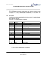
ISSUE CONTROL
Issue
Date
Remarks
01
23.01.06
First Issue
02
24.01.06
Production Issue
03
03.04.06
CN10652
04
27.06.06
CN10648
05
15.09.06
Section 10 added
06
26.06.07
ESFIRECODER-1 & ESFIRECODER-2 variants added
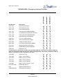
CONTENTS
Section
Title
1
Introduction
2
Safety Warning
3
Technical Specifications
4
User Guide
5
Installation & Commissioning
6
ESFIRECODER Software
7
Spares and Repairs
8
Technical Assembly
9
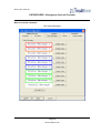
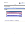
Typical Software Screen Dumps
10
Compliance Information
Page 2
www.multitone.com
9261-7974 Issue 06
ESFIRECODER - Emergency Services Firecoder
SECTION 1 – INTRODUCTION
This technical manual describing the installation and operation of the ESFIRECODER Emergency
Services Firecoder and variants of.
1.1
OVERVIEW
The ESFIRECODER has been designed to meet the requirements for Emergency Service station
ends, both Whole time and Retained. The hardware has evolved through 3 generations to the present
platform. The software protocols used for communications are the Home Office protocol GD92
version GD-92/1003A/2.2 and the Home Office specification MG4 for alerting. The protocol is a
“closed loop” system, thus ensuring message delivery. In addition to system messages, the unit can
deliver “unsolicited” messages to a GD92 Network Manager. This gives the system a degree of selfmonitoring, essential for an Emergency service. Remote diagnostics/configuration are inherent within
the unit.
The ESFIRECODER has Home Office accreditation
The equipment can deliver solutions pertinent to a particular authority by programming the unit to
perform the functions required.
The unit is a self contained programmable GD92/MG4 system complete with:
•
Router
•
Peripheral Agents
•
Printer agents
•
Communication Agents (LAN/Wan, PSTN, Tetra, etc)
•
Wide area agents
•
Alerter agent
•
File Transfer support using GD92 bearers
The system will accept messages from a control centre and deliver the appropriate message to:
•
Alerters
•
Printers
•
Public address systems
•
Message boards
•
Peripheral devices
Delivering to the originator acknowledgements of success or failure.
Complimentary to the ESFIRECODER are the Multitone Central Communications Processor (CCP)
and the Multitone Network Manager (NSM), both units generally residing in the control centre.
Page 3
www.multitone.com
9261-7974 Issue 06
ESFIRECODER - Emergency Services Firecoder
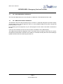
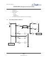
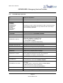
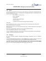
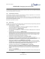
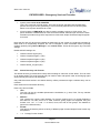
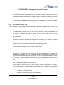
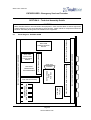
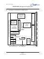
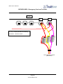
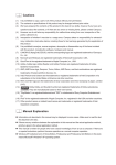
1.2
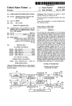
BLOCK DIAGRAMS
ESFIRECODER
UPI
UPI
UPI
UPI
BACK PANEL
MINI ITX
Audio Isolation
PSU 13.5v -> 12.0v
Serial Port / USB
LAN USB
Printer Serial
Video
Audio
Keyboard & Mouse
ATX PSU
USB
USB HUB
IDE
BUS
FRONT PANEL
EXTENDED STORAGE
LCD Display
User Keys
User LEDs
UFI
Mains Fail Detection
Hard Drive
or
Flash Memory
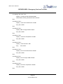
ESFIRECODER-1 & ESFIRECODER-2
RF LINK UNIT (ESFIRECODER-2 only)
UPI
COM3
UPR
UPI
UPI
BACK PANEL
MINI ITX
Audio Isolation
PSU 13.5v -> 12.0v
Serial Port / USB
LAN USB
Printer Serial
Video
Audio
Keyboard & Mouse
ATX PSU
USB
USB HUB
IDE
BUS
FRONT PANEL
EXTENDED STORAGE
LCD Display
User Keys
User LEDs
UFI
Mains Fail Detection
Hard Drive
or
Flash Memory
Page 4
www.multitone.com
9261-7974 Issue 06
ESFIRECODER - Emergency Services Firecoder
1.3
UPI - USB PERIPHERAL INTERFACE
This Technical Manual does not cover this part, for details see Technical Manual 9261-7909
1.4
UFI - USB FRONT PANEL INTERFACE
The Multitone USB Front Panel Interface (UFI) is a USB V1.1 peripheral designed to provide a display
and user keys for PC. The UFI appears to the PC to be a standard COM port and uses a simple text
protocol (UPIP) for control.
For engineering and test purposes, any PC serial program can be used to send UPIP commands to
the UFI.
A UFI can be connected up to 5m from the PC (this is a limitation of the USB interface).
The USB socket provides two diagnostic LED’s. The Green LED is normally on when the UFI is active,
and flashes off when data is received on the USB port. The Red LED will pulse when the watchdog is
updated and flash when the watchdog has timed out.
Page 5
www.multitone.com
9261-7974 Issue 06
ESFIRECODER - Emergency Services Firecoder
SECTION 2 - SAFETY WARNING
2.1
COMPANY LIABILITY
The information in this manual has been carefully compiled and checked for technical accuracy.
Multitone Electronics plc accept no liability for inaccuracies or errors. In line with the company policy
of technical advancement, the information within this document may be changed. The user should
ensure that the correct issue of the document is used. Comments or correspondence regarding this
manual should be addressed to:
Multitone Electronics plc
Technical Publications
Hansa Road
Hardwick Industrial Estate
Kings Lynn
Norfolk
PE30 4HX
England
2.2
SAFETY SUMMARY
The following information applies to both operating and servicing personnel. General Warnings and
Cautions will be found throughout the manual where they apply.
WARNING statements identify conditions or practices that could result in personal injury or loss of life.
CAUTION statements identify conditions or practices that could result in equipment damage.
Page 6
www.multitone.com
9261-7974 Issue 06
ESFIRECODER - Emergency Services Firecoder
SECTION 3 - TECHNICAL SPECIFICATIONS
CONTENTS
3.1
PHYSICAL SPECIFICATIONS
3.2
ELECTRICAL SPECIFICATIONS
3.3
ENVIRONMENTAL SPECIFICATIONS
3.4
FRONT PANEL ACCESS FACILITIES
3.5
BACK PANEL I/O PORT FACILITIES
3.6
BACK PANEL WIRING SCHEMATICS
Page 7
www.multitone.com
9261-7974 Issue 06
ESFIRECODER - Emergency Services Firecoder
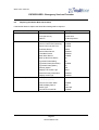
3.1
PHYSICAL SPECIFICATIONS
Weight
7.1 kgs
External dimensions (H x D x W)
132 x 422 x 483 mm
Housing material
Mild Steel (Zinc plated and passivated)
3.2
ELECTRICAL SPECIFICATIONS
3.2.1
Input 3 Pin XLR
•
3.2.2
Input Voltage 24v DC Nominal (22v DC – 30v DC)
• Input Current - dependant upon power source & ancillary attachments
Ancillary Output Voltages
•
3 x 3 Pin XLR 24v DC Nominal - fused options up to 8A
3.2.3
• 2 x 4 Pin XLR 13.5v DC Nominal - fused options up to 8A
The unit draws 700ma quiescently
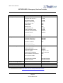
3.3
ENVIRONMENTAL SPECIFICATIONS
3.3.1
Temperature
•
3.3.2
• External forced cooling required above +40°C
Humidity
•
3.4
3.5
Operating Range 0°C to +50°C
Up to 90% RH (Non-condensing)
FRONT PANEL ACCESS FACILITIES
•
Two Line LCD Status Display
•
Local Activation of User Defined Menu Options
•
Manual Acknowledgement & Reprint Facility
•
Six Status LEDs
•
Three User Defined LEDs
BACK PANEL I/O PORT FACILITIES
•
4 x UPIs (USB Peripheral Interfaces)
•
2 x RS232 Serial Ports
•
1 x PS2 Mouse Port
•
1 x PS2 Keyboard Port
•
1 x Parallel Port
•
1 x RJ-45 LAN Port
Page 8
www.multitone.com
9261-7974 Issue 06
ESFIRECODER - Emergency Services Firecoder
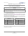
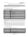
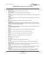
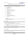
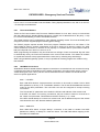
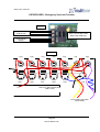
3.6
•
1 x VGA Port
•
2 x USB 2.0 Ports
•
3 Audio Jacks
Line In
Line Out
Microphone In
•
2 x Transformer (600 Ω) Isolated Line Out (Left & Right)
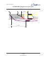
BACK PANEL WIRING SCHEMATICS
24v
FS6
1
1
3
PL1
2
0v
4
FS2
24 / 12v
Converter
8A
FS7
FS4
8A
FS5
8A
12v
4
FS1
24v
SK1
8A
1
0v
2A
FS3
SK4
8A
0v
MAINS FAILURE
Front Panel PCB
12v
8A
3
24v
SK2
2
SK3
2
1
24v
1
0v
Page 9
www.multitone.com
0v
Rear Panel PCB
2
1
SK5
9261-7974 Issue 06
ESFIRECODER - Emergency Services Firecoder
SECTION 4 - USER GUIDE
No user guide is available for this product.
Page 10
www.multitone.com
9261-7974 Issue 06
ESFIRECODER - Emergency Services Firecoder
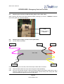
SECTION 5 - INSTALLATION & COMMISSIONING
WARNING
Do not install / use the equipment in areas where explosive gases may be present.
CAUTION
Do not install / use the equipment where it may be exposed to liquids, strong magnetic fields,
extreme temperatures or strong sunlight.
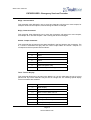
5.1
UFI - USB FRONT PANEL INTERFACE
The UFI requires a set of PC drivers for operation. These are standard drivers, and can be
downloaded from the FTDI web site at http://www.ftdichip.com/FTWinDriver.htm or can be loaded
directly using the Windows Online update facility. Only a single set of drivers need be installed no
matter how many UFI's are connected to a system.
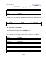
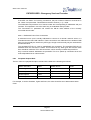
Once installed, the UFI is automatically assigned a COM port. This may be changed using the
Windows Control Panel, and it is recommended the COM ports from 10 upwards are used to avoid
any conflicts with existing COM ports. Standard allocations are:
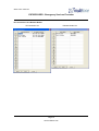
ESFIRECODER-1 & ESFIRECODER-2
ESFIRECODER
COM Port
Peripheral
COM Port
Peripheral
COM 10
Console Agent (UFI)
COM 10
Console Agent (UFI)
COM 11
1st Peripheral Agent (UPI)
COM 11
1st Peripheral Agent (UPI)
COM 12
2nd Peripheral Agent (UPI)
COM 12
2nd Peripheral Agent (UPI)
COM 13
3rd Peripheral Agent (UPI)
COM 3
3rd Serial Port
COM 14
4th Peripheral Agent (UPI)
COM 15
4th Printer Agent (UPR)
Please note that if FTDI's D2XX drivers are installed on the PC, they must be removed following
FTDI's instructions prior to installing the required VCP drivers. Drivers for Linux operating systems are
also available from the FTDI web site.
Page 11
www.multitone.com
9261-7974 Issue 06
ESFIRECODER - Emergency Services Firecoder
5.1.1
Operating Mode
The UFI provides an interface to a 2 line, 24 character LCD display, up to 5 buttons, 3 input
channels and up to 6 LED's. A watchdog is also provided for the PC - once enabled, if the
watchdog is not updated every few seconds, the PC will automatically be rebooted.
5.1.2
UPIP Protocol
Each UPIP command sent to or from the UFI consists of a standard ASCII text line followed by
a CR (0D hex). A command will normally produce one or more lines of response, generally
starting with a lower case letter.
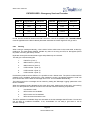
The first letter of the line determines the command type.
Command
Response
Notes
Sh{h}
ohhhh
Set one or more outputs
Rh{h}
ohhhh
Reset one or more outputs
Ohhhh
ohhhh
Set ALL outputs
Ttext
ohhhh
Send text to display
Bhh
bhh
Backlight control
Utttttttt
u
User defined display character
Wh
w
Watchdog control
A
error
Prevent modem detection
E
en
Echo command input
M
mF
Return operating mode
Q
o00hh
Query Status
I
i00hh
Read Buttons/Inputs
V
vversion
Get software version
Ntext
ntext
Save/Read Non-Volatile text
Gtext
ghhhhhhhh
Generate Key
l status
Loop back test
L
Where:
hhhh is a 16 bit hex word, expressed as four hex characters
hh is a 8 bit hex byte expressed as two hex characters
Page 12
www.multitone.com
9261-7974 Issue 06
ESFIRECODER - Emergency Services Firecoder
Sh{h} - Set Command
This command, when followed by one or more hex characters, will set one or more outputs, for
example "S046" will set outputs 0,4 and 6 leaving the others unchanged.
Rh{h} - Reset Command
This command, when followed by one or more hex characters, will reset one or more outputs,
for example "R17" will reset outputs 1 and 7 leaving the others unchanged.
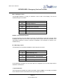
Ohhhh - Output Command
This command sets all outputs to the states specified in the four following hex characters. The
O, S and R commands will reply with the current output states as "ohhhh". Outputs 0..5
correspond to the front panel LED's as follows:
Channel
LED
0
User 1
1
User 2
2
User 3
3
Fault
4
Flash Red (Mains Fail)
5
Flash Green (Low Battery)
Ttext - Text for Display
This command allows text to be sent to the display, so it is only valid when the unit is in front
panel mode. Up to 250 characters may be sent in a single line. The following special display
control commands are available:
Character
Function
\f
Clear Display
\r
Move cursor to start of line 1
\n
Move cursor to start of line 2
\t
Clear to end of line
\\
Display a single \ character
\u
Display user defined symbol
\d
Display 'delete' symbol
Page 13
www.multitone.com
9261-7974 Issue 06
ESFIRECODER - Emergency Services Firecoder
Bhh - Backlight Control
The backlight defaults to coming on whenever a text is sent to the display. This can be
modified using this command:
Command
Function
B00
Backlight always off
B01
Backlight on for 1 second
B02
Backlight on for 2 seconds
…
BFE
Backlight on for 254 seconds
BFF
Backlight always on
Utttttttt - User Defined Character
A single character (\u) on the display can have a user-defined font using this command. Eight
characters are used; the low 5 bits of each define each of the 8 rows of the character. If no
user-defined character is stored, a diamond is displayed. This information is stored in nonvolatile memory.
W - Watchdog Control
The watchdog can be enabled, disabled or reset using this command
Character
Function
W
Reset Watchdog Timer
W0
Disable Watchdog
W1
Enable Watchdog, 1 second timeout
…
WF
Enable Watchdog, 15 second timeout
If the watchdog is enabled, but not reset within the configured time, the reset output will be
asserted to reset the PC.
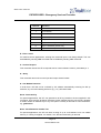
I - Input Command
This command will request the current input states, returning i00hh. It is normally not needed
as an i status line will be sent whenever an input changes. Input bits:
Page 14
www.multitone.com
9261-7974 Issue 06
ESFIRECODER - Emergency Services Firecoder
Channel
Function
0
"Back" Button
1
"Fwd" Button
2
"Exec" Button
3
"ManAck" Button
4
"Repeat" Button
5
Input 6 Asserted (Active Low)
6
Input 7 Asserted (Active Low)
7
Input 8 Asserted (Active Low)
E - Echo Control
For machine driven applications, echoing the command input is not always helpful. This can
be disabled by sending a E0 command and re-enabled by sending a E1 command.
V - Version Request
This command causes the UFI to respond with its current software version, preceded by a v
Q - Query
This command returns the current input and output channel states.
A - Anti Modem Detection
In order that a UFI will not be confused by PC software automatically scanning for dial up
modems, any command starting with an A (e.g. ‘AT’) will return error.
Gtext - Generate Key
For special applications, the UFI can generate a 32 bit key based on the text supplied in this
command. There must be at least 8 characters of text supplied, and the unit will only generate
a certain number of different keys in any time period. The key is returned as 8 hex characters,
e.g. ghhhhhhhh.
Ntext - Save/Read Non-Volatile Text
For special applications, the UFI can store a string of up to 32 characters in its non-volatile
memory. If a string is supplied, it is stored, if not, the last stored string is returned.
Page 15
www.multitone.com
9261-7974 Issue 06
ESFIRECODER - Emergency Services Firecoder
Ptext - Save Powerup Text
When the UFI powers up, it displays its version string and Initialising. This command can be
used to store an alternative message (up to 64 characters) to display until the main application
is running.
L - Loopback Tests
These tests are to check the basic UFI hardware is working correctly, and while running, will
cycle through the outputs. If a button is pressed, it will be displayed and shown on the PC. The
test will timeout after a few seconds if no button is pressed.
Page 16
www.multitone.com
9261-7974 Issue 06
ESFIRECODER - Emergency Services Firecoder
SECTION 6 – ESFIRECODER SOFTWARE
6.1
MULTITONE GD-92 FIRECOMMS+
The Multitone GD-92 Firecomms+ system consists of a software suite that uses the GD-92 protocol to
link various systems via one or more bearers. Systems can communicate with the real world using a
variety of agent types.
The system currently consists of three different programs with the main communications program
being available in two formats:
•
MFWC is the main communications program that runs on Windows systems, normally as a
system service. This program runs the various user agents and message transfer agents that
make up a GD-92 system, and would normally be configured to run continuously.
•
MFWL is the same communications program built to run on Linux systems. (Future Product)
•
MFW is the engineering front-end program that runs on Windows systems and is used to
configure, test and monitor the system.
•
MFU is a user front end program that runs on Windows systems and is used to configure, test
and monitor the system.
•
MFWS is a small application that provides a simple full screen display for a Windows (Windows
2000, XP or later) system
The engineering and user programs are connected to a communications program by an IP link, and
each will often be on different systems.
6.1.1
MFWC - Firecomms Communications Software
MFWC is a program that runs on 32 bit Windows systems; Windows 2000, XP or later and
runs the actual Firecoder communication system.
It can be run from the command line, or installed as a system service.
MFW is used to configure, monitor and test the system.
6.1.1.1 Command Line Operation
MFWC can be run from the command line (or by double clicking on the program in an explorer
window, or of course using a Windows shortcut). In this mode, basic logging information will
be shown on the screen. If the system is shutdown, or the current user logs off, the program
will be correctly shutdown.
Normally, the directory and configuration to use will be supplied as a parameter when the
program is run.
Example Commands:
MFWC
MFWC config
MFWC path\config
MFWC \\machine\path\config
Page 17
www.multitone.com
9261-7974 Issue 06
ESFIRECODER - Emergency Services Firecoder
MFWC d:\path\config
MFWC d:\path
With no parameters, MFWC runs using the default configuration in the current directory.
If a configuration file is specified (optionally with a relative or absolute path), then that
directory/file will be used instead. UNC filenames are also supported.
If you wish to specify just a directory but still use the default configuration name, ensure that
there is trailing slash on the config name, otherwise the parser will use the 'last' folder name
as the configuration file name.
In operation, MFWC displays basic system activity. F10 or Alt-X will terminate the program.
6.1.1.2 System Service
MFWC can also install itself and run as a system service. In this case, there is no visible
output, but the program can be set to run at start-up with no user logged in. The service will
also be automatically terminated when the system is shutdown.
A local or remote copy of MFW can communicate with it for program set-up.
Service commands:
MFWC -install config
MFWC -install path\config
MFWC -install \\machine\path\config
MFWC -install d:\path\config
MFWC -remove
MFWC -stop
MFWC -start
These commands control the operation of MFWC as a system service.
The -install switch will install and automatically start the service (and it will restart on the next
boot). Ensure a valid configuration is supplied, otherwise the program will use the default
configuration name in the same directory as the program itself.
The -remove switch will stop the service and remove it from the system table.
The -start and -stop switches will start and stop an installed service. These can be useful for
software upgrades; the service can be stopped, the .exe updated, then restarted.
This program will also be available to run on Linux systems - see MFWL for more details.
Page 18
www.multitone.com
9261-7974 Issue 06
ESFIRECODER - Emergency Services Firecoder
6.1.2 MFW - Firecomms Engineering Software
MFW is a program that runs on 32 bit Windows systems; Windows 2000, XP or later. It
communicates with a Firecoder or a Firecomms System program using an IP link, and can
be used to configure, test and monitor a system either locally or remotely.
MFW can also send basic GD-92 commands to older systems via a Firecoder or a
Firecomms System.
6.1.2 MFU - Firecomms User Interface
MFU is a program that runs on 32 bit Windows systems; Windows 2000, XP or later. It
communicates with a Mobilise Agent on a Firecomms System using an IP link, and can be
used to send commands to, and receive status messages from, the system.
6.1.3 MFWS – Firecomms Full Screen Display
MFWS is a program runs on 32 bit Windows systems; Windows 2000, XP or later. Normally
MFWS would be driven by a Display Agent, but in principle, it can be driven by any program
capable of sending text to it.
6.2
ROUTER AGENT
6.2.1
Brigade/Node Number/Names
The brigade number is assigned by the Home Office, and is unique for each brigade. Each
node in a brigade MUST have a different node number. When changing the brigade or node
number, remember that the node will then only respond to commands sent to the new
brigade/node number once that node has been reset.
The Node Name contains the text name of the current node. The Station Code contains a
short name for reports - this string is also included in the name of log files saved to disk.
6.2.2
Software Version
This shows the current node software version.
6.2.3 Router Table
The router table at a node describes the routes available by each bearer type from this node
to other nodes, either directly or indirectly via a directly connected node.
A separate entry is required for each bearer type; the preference parameter specifies the order
in which the routes will be tried (1=Highest). Only routes with the "Used" flag set to "Y" will be
used.
To specify a route to a destination directly connected to this node, specify the destination in
the 'NextNode' field and leave the 'Destination' field set to zero.
If a range of nodes is directly connected to this node via the same bearer type, leave the
'NextNode' field set to zero and specify the range of addresses that are directly connected in
the 'Destination' field.
Page 19
www.multitone.com
9261-7974 Issue 06
ESFIRECODER - Emergency Services Firecoder
For bearers capable of broadcast transmission (normally just some radio bearer types), leave
the 'NextNode' field set to zero and specify the range of addresses the bearer is connected to
in the 'Destination' field.
For an indirect route, the 'NextNode' field contains the node address of the node actually
connected to this node; the 'Destination' field specifies the range of nodes accessible (directly
or indirectly) from 'NextNode'.
6.3
PSTN/GSM/ISDN/WAN Tables
6.3.1
Dial-up table
The dial-up tables at a node tell the router which number a particular bearer should use to
connect to a node.
NextNode
Number
Used
- Next node address
- Number (or NUA) for the NextNode
- Set to "Y" if entry used, "N" or blank if not.
- Set to "U" if entry is used but unavailable.
Hold
- Maximum hold time (seconds) for that node.
If the hold time is not zero, the link will be disconnected when the link is unused for longer than
the hold time.
6.3.2
Radio Table
The radio tables are used by various agents to lookup the external address or channel of the
node.
Used
NextNode
Number
Used
- Set to "Yes" if this line is used.
- Next node address
- Number for the node
- Set to "Y" if entry used, "N" or blank if not.
- Set to "U" if entry is used but unavailable.
Hold
6.4
- Maximum hold time (seconds) for that node.
Max Data Length
This parameter specifies the maximum message length that is sent by this node.
It should normally be set to 1023 unless bearers with limited maximum message lengths are used.
Page 20
www.multitone.com
9261-7974 Issue 06
ESFIRECODER - Emergency Services Firecoder
A message longer than this parameter will still be processed by the node; this parameter primarily
controls the number of parameters returned in a message and the length of printer message blocks.
6.5
Primary/Secondary Network Manager
If a node needs to send an unsolicited message advising of a bearer status change (e.g. link failed),
these parameters specify the destination of these messages.
If a message sent to the Primary Network Manager fails to route at a node, it will automatically be rerouted to the Secondary Network Manager address if this is specified.
6.6
Unsolicited Message Address & Priority
If a user agent detects a change in status and needs to inform someone, the address is used as the
destination for the unsolicited message. These are normally generated as follows:
Peripheral agents: Input active and alarm messages.
Printer agents:
Printer on/off line/out of paper.
Alerter agents:
Local alerts made, transmitter errors
Normally, all unsolicited messages are sent with message priority 3. For specific applications, the
priority field allows any priority from 1 to 9 to be used for these messages.
If this field contains 0, the default priority is used.
The combination of this parameter and the "Test" priority facility of the MTA's can be used to direct
unsolicited messages via specific bearers.
If the Network Tester is used, the upper digit of this field can be used to specify the priority of failure
messages sent to the mobilising system.
6.7
No_ACK Timeout
This parameter specifies the maximum number of seconds that an application waits for a response to
a command. It is only used for "applications" (e.g. the standby alerter) rather than fire stations.
6.8
Manual Acknowledge Timeout
This parameter specifies the maximum number of seconds that a user agent should wait for a manual
acknowledge to a command.
6.9
Data-log Everything
Each Multitone node logs events to a time stamped history log. If this parameter is set to "Yes", then
all events will be logged. If is set to "No", certain basic events will not be logged:
Page 21
www.multitone.com
9261-7974 Issue 06
ESFIRECODER - Emergency Services Firecoder
Messages transmitted and received.
Station inputs changing from "On" to "Off"
Data blocks printed.
Transmitters "On" and "Off"
Coverage and out-of-range calls.
6.10
Agent Manager
All agents have an Agent Manager, that monitors events from that agent and selected GD-92
messages sent to the agent. Either can be used to trigger other actions to happen, via either local or
remote agents.
When the Agent Manager processes an event or message, the Agent Manager configuration is
scanned from the top for a matching expression. If a match is found, the specified action(s) are carried
out and processing finishes. However, if the keyword “CONTINUE” is included on a matching line,
scanning will continue through the configuration.
An expression may extend over several lines, and contain one or more comparison statements and
one or more command statements. If more that one comparison statement is used, ALL must match
for that expression to be valid.
The Agent Manager is also called once per minute in order to match time-based commands. This
allows events to be triggered purely on time and day of the week.
Comments may be included, by starting the line with a hash (#). Blank lines are ignored.
Page 22
www.multitone.com
9261-7974 Issue 06
ESFIRECODER - Emergency Services Firecoder
6.11
Event/Message Keywords:
IF
Start of an expression
TIME hh:mm-hh:mm
TRUE if current time is in range specified
TIME hh:mm
TRUE at that exact time only
MONDAY
TUESDAY
WEDNESDAY
THURSDAY
FRIDAY
SATURDAY
SUNDAY
Normally, the day of week is ignored but if ANY of these keywords
are included, the expression is only matched if the current day is
ANY of the days specified
WEEKDAY
This is a shortcut for MONDAY-FRIDAY
WEEKEND
This is a shortcut for SATURDAY-SUNDAY
SOURCE b:n:p
Matches a source address
SOURCE b:n:p-b:n:p
Matches a source address range,
where b = brigade, n = node, p = port.
Use a * anywhere for a wildcard. e.g.
*:*:30, 10:100:*-10:299:*
Each section is compared independently
TEVENT hh:mm
Specifies a timed event
TEVENT hh:mm-hh:mm
Specifies an event for each minute in range
EVENT evnt
Matches an event generated by the agent
EVENT evnt*
Wildcard match an event (See detailed list of event codes later)
PERISTAT
Matches any peripheral status message
PERISTAT x1xxx0xx
Matches a particular status message
Each character matches an input 0..15 in sequence:
0 = Channel 0, 1 = Input 1, x = Don't Care
TEXTMESG
Matches ANY text message
TEXTMESG n
Matches the first block of a text message starting with number n, e.g.
TEXTMESG 20 would match 20Status Update
TEXTMESG "tok1 tok2,..."
Matches sequential tokens specified in the first block of a text
message
e.g. "Zone Alarm" would match "This is a Zoned Alarm"
A # will match one or more numbers, so
"Zone #" would match Zone 43, Zone 999 etc
MOBSMESG
Matches ANY mobilise message
PAGEMESG
Matches any Page_Officer message
Page 23
www.multitone.com
9261-7974 Issue 06
ESFIRECODER - Emergency Services Firecoder
PAGEMESG r
Matches Page_Officer message with RIC matching r
r may include * as a wildcard, e.g. 12345*, 123****
ALRTSTAT
Matches any alerter status message
ALRTSTAT xx
Matches an alerter status message xx
Asterisks can be used as wildcards in either character. Examples:
fa, t*, x*,**
MOBSTAT
Matches any mobilise status message
MOBSTAT x
Matches mobilise status message 'x'
1 = MobStat 1 ... 8 = MobStat 8
a = MobStat a ... h = MobStat h
PRNTSTAT
Matches any printer status message
PRNTSTAT n
Matches printer status message 'n'
0 = Off Line, 1 = Paper Out, 2 = On Line
MTASTAT
Matches any MTA status message
MTASTAT n
Matches MTA status message type 'n'
0 = Idle, 1 = Online, 2 = Shutdown, 3 = Fault, 4 = Modem Error,
5 = Engaged, 6 = No Carrier, 7 = No Answer, 8 = No Dialtone,
9 = No Logon
RESET
Matches any reset message
RESET n
Matches reset message type 'n'
0 = Requested, 1 = Software, 2 = Power On
AND
Joins multiple statements together
6.12
Command Keywords:
TIMER t = n
Set timer t to expire after n seconds
TIMER t1 = n1, t2 = n2
Set multiple timers. Set n = 0 to stop timer
PRINT "message"
Prints message to default printer
PRINT addr "message"
Prints message to address specified addr is in the form
brig:node:port The GD92 priority of the message can be set by
appending ",p" to addr, where p is 1 to 9, e.g. 99:99:30,5
DISPLAY "message"
Sends message to default mobs agent
DISPLAY addr "message"
Sends message to address specified
PAGE ric "message"
Send admin page to ric using the default Alerter.
PAGE ricM "message"
Send page to ric using the default Alerter. M sets the MG4 priority
and may be E,P,R or A.
Page 24
www.multitone.com
9261-7974 Issue 06
ESFIRECODER - Emergency Services Firecoder
PAGE team "message"
Send page to team using the default Alerter. If no message is
required, then the quotes must still be supplied.
PAGE addr dest "message"
As above, but pages using an Alerter at addr.
SEND dest "message"
Sends page to the default Paging Agent. dest is one or more
destinations or commands accepted by the paging agent seperated
with commas.
SEND addr dest "message"
As above, but uses a Paging Agent at addr
PLAY "file"
Play sound file specified on default Sound agent
PLAY "file1,file2"
Play sound files specified
ACTIVATE n
Activate channel n on default peripheral agent
ACTIVATE xxxx
Activate multiple channels (hex)
ACTIVATE addr cmd
Activate channels on other peripheral agent
DEACTIVATE n
Deactivate channel n on default peripheral agent
DEACTIVATE xxxx
Deactivate multiple channels (hex)
DEACTIVATE addr cmd
Deactivate channels on other peripheral agent
SENDPERISTAT n
Send Input Peripheral Status with channel n active to Network
Manager
SENDPERISTAT xxxx
Send Input Peripheral Status xxxxhex to Network Manager
SENDPRNTSTAT n
Send Printer Status n to Network Manager 0 = Off Line, 1 = Paper
Out, 2 = On Line
REPEAT
Send Repeat Message command to default printer agent
SENDMTASTAT dest n
Send MTA Status Change n to an MTA
1 = Idle/On-Line, 2 = Shutdown
EMAIL dest "msg"
Send email to destination with message. This uses the default Email
agent.
COPY addr
Copy original message to address
CONTINUE
Continue scanning after a match was found
COPY address
Copy original message to address
REQTIME address
Request clock time from address specified
END
Terminates an expression
For those commands that have a default agent, the Agent Manager will use the agent of the
appropriate type on the local system with the lowest port number. This can be changed to any other
agent, either on the local system or a remote system, by adding a suitable entry to the Destination
Table with the form DFLT_agentname with the GD-92 address of the agent.
Page 25
www.multitone.com
9261-7974 Issue 06
ESFIRECODER - Emergency Services Firecoder
Notes
The page command will use an Alerter_1 agent type if no Alerter_2 type is found.
The Agent Manager for a Peripheral or Console Agent will default to sending ACTIVATE
and DEACTIVATE commands to itself unless a destination for the message is specified.
PRINT
DFLT_Printer
DISPLAY
DFLT_Mobilise
PAGE
DFLT_Alerter_2 or DFLT_Alerter_1
SEND
DFLT_Paging
PLAY
DFLT_Sound
ACTIVATE
DFLT_Peripheral
DEACTIVATE
DFLT_Peripheral
EMAIL
DFLT_Email
6.13
Agent Events: Peripheral/Console /Remote Console/Button Box Agents
This agent type will send the following events to the agent manager:
chan:On
Channel On
chan:Off
Channel Off
chan:Wait
Wait before turnoff
chan:Regen
Regenerated message sent
chan:Moni
Channel monitored OK
chan:Fail
Monitoring failed
chan:Mobi
Channel mobilised
chan:Actv
Channel activated
chan:Deac
Channel deactivated
Command:n
UFI Front Panel command
Command:Fx
Button Box Fire (x = A, B, C, AB, AC, BC, ABC)
Command:Tx
Button Box Test (x = A, B, C, AB, AC, BC, ABC)
Command:FT
Button Box Engineering Command
Tones:xxxx
Tone Sequence xxxx received from LPI
chan is the configured name of the channel, but with any spaces changed to underscores.
A chan:Wait event is sent 60 seconds before an output turns off. However, if the configured time for
the output is less than 60 seconds, the event is sent when half the time has elapsed.
Page 26
www.multitone.com
9261-7974 Issue 06
ESFIRECODER - Emergency Services Firecoder
As an asterisk (*) is used for a wildcard string match, any DTMF * codes are sent to the Agent
Manager as S(tar) characters, and any DTMF # codes are sent as H(ash).
6.14
Agent Events: Alerter_2 Agents
This agent type will send the following events to the agent manager:
MG4:xx
MG4 error
Alrt:Fx
Fire Call (x = A..J)
Alrt:Tx
Test Call (x = A..J)
Alrt:PE
Emergency Officer Page
Alrt:PP
Priority Officer Page
Alrt:PR
Routine Officer Page
Alrt:PA
Admin Officer Page
Alrt:PN
Engineering Page
Covr:On
Coverage Test On
Covr:Off
Coverage Test Off
Engn:x
Engineering Command
This agent will send a Page_Officer message to the Agent Manager for every original page actually
transmitted by the agent (i.e. not including repeats). This is done following any directory translation
and expansion.
The source address of the Page_Officer message will be the original source address of the command
sent to the Agent, or in the case of internally generated Coverage pages, the address of the alerter
agent itself.
This facility would typically be used to forward a "fill-in" page to another alerter. To assist in this, the
GD-92 call type (normally Alpha or Numeric) is set to the beep code (1-8) of the locally sent page.
On receipt of this special message type, the destination alerter will override the default beep code for
that call type and send a page with the same beep code and message format as the original call.
6.15
Agent Events: Paging Agent
This agent will send the following events to the agent manager:
Event
Action
Page:Successful
Page Successful
Page:Unconfirmed
Unconfirmed Page Complete
Page:Failed
Page Failed
Page:<error_text>
Page Failed with specified error text
Page 27
www.multitone.com
9261-7974 Issue 06
ESFIRECODER - Emergency Services Firecoder
A failure will produce both a Page:Failed event AND a specific Page:<error_text> event, where
<error_text> is a standard GD-92 error code but with all non-alphanumeric characters replaced with
underscores, e.g.
Page:No_Bearer
Page:TXA_Fail
Page:TXB_Fail
Page:Encoder_Fail
This agent will also pass all incoming Page_Officer messages to the Agent Manager for optional
processing with the PAGEMESG command.
6.16 Agent Events: Paging Input Agent
This agent will send the following events to the agent manager:
Event
Action
Link:Fail
Link to external system failed
Link:OK
Link to external system OK
This agent will pass all incoming Page_Officer messages to the Agent Manager for optional
processing with the PAGEMESG command.
6.17
Agent Events: Sound Agent
This agent type will send the following events to the agent manager:
Play:sound
Play sound specified
Queue:sound
Queue sound specified
NoFile:sound
No file found for sound
Gate:On
Audio Gate On
Gate:Off
Audio Gate Off
The Audio Gate is activated before the agent plays any sounds, and is deactivated after all sounds
have been played.
Page 28
www.multitone.com
9261-7974 Issue 06
ESFIRECODER - Emergency Services Firecoder
6.18
Agent Events: Network Manager
The Network Manager has no specific events associated with it, but will acknowledge and pass the
following message types to the Agent Manager:
MTA Status
MTASTAT
Printer Status
PRNTSTAT
Peripheral Status
PERISTAT
Alerter Status
ALRTSTAT
Page_Officer Message
PAGEMESG
Text Messages
TEXTMESG
Reset
RESET
6.19
Agent Events: Mobilise Agent
This agent will send the following events to the agent manager:
Event
Action
Link:OK
Link to PC OK
Link:Fail
Link to PC failed
6.20
Agent Events: Printer Agent
This agent type will send the following events to the agent manager:
Mobs
Mobilise Message Received
Admin
Administration Message Received
Mobs:n
Mobilise Message type n Received
Mobilise:n
Mobilise Message type n Printed
Callsign:xxxx
Callsign xxxx Printed
Repeat:n
Repeat Mobilise Message type n Printed
RepeatCall:xxxx
Repeat Callsign xxxx Printed
Finish:n
Finish Mobilise Message type n Printed
Firetype:xxxx
Mobilise Fire Type xxxx
Wholetime:xxxx
Type 6 Wholetime Mobilise turnout type xxxx
Retained:xxxx
Type 6 Retained Mobilise turnout type xxxx
NoPower
No Printer Power
Page 29
www.multitone.com
9261-7974 Issue 06
ESFIRECODER - Emergency Services Firecoder
NoPaper
No Printer Paper
Offline
Printer Offline
Error
Printer Error
PaperLow
Printer Paper Low
This agent will also pass incoming text and mobilise messages to the Agent Manager for optional
processing with the TEXTMESG and MOBSMESG commands. If the printer status changes, a
PRNTSTAT message will also be sent to the Agent Manager.
Message Type 6 turnout types:
•
Standard
•
Batched
•
Standby-Home
•
Motorway
•
Standard-Home
•
Pre-Alert.
•
Standby
•
Motorway-Home
6.21
Agent Events: Scroll-board Agent
This agent has no specific events associated with it, but will pass all incoming text messages to the
Agent Manager for optional processing with the TEXTMESG command.
6.22
Agent Events: Message Transfer Agents (MTA's)
Each time the status of an MTA changes, the following events will be sent to the Agent Manager:
MTA:Idle
MTA Idle
MTA:Dial
MTA Dialling
MTA:Fail
MTA Failed
MTA:Conn
MTA Connecting
MTA:Answ
MTA Answering
MTA:Lstn
MTA Listening
MTA:Incm
MTA Incoming connection
MTA:Unkn
MTA Unknown number
MTA:Voic
MTA Answering Voice Call
MTA:OnLn
MTA Online
MTA:Falt
MTA Fault
MTA:OffL
MTA Offline
MTA:Busy
MTA Busy
Page 30
www.multitone.com
9261-7974 Issue 06
ESFIRECODER - Emergency Services Firecoder
MTA:Shut
MTA Shutdown
Fail:Modem_Error
Modem Failed
Fail:Line_Engaged
Line Engaged
Fail:No_Carrier
No Carrier
Fail:No_Answer
No Answer
Fail:No_Dialtone
No Dial-tone
Fail:Modem_Blacklisted
Number Blacklisted
Fail:No_Logon
Logon Failed
6.23
Agent Events: Router
Each time that a system status bit changes, an event message is sent to the Router Agent Manager
as follows:
Event
Action
Mains_Fail
Mains Power Failed
Mains_OK
Mains Power Restored
Battery_Low
Backup Battery Low
Battery_OK
Backup Battery OK
ManAck_Wait
Waiting for ManAck
ManAck_OK
ManAck Acknowledged
System_Fault
System Fault (Transmitter Error)
System_OK
System OK
DupSys_Active
Duplicate System Active
DupSys_InActive
Duplicate System Inactive
Example:
IF EVENT Mains_Fail THEN PLAY “POWERFAILED” END
Do not confuse these events with the system status keywords, which are used to qualify an
expression:
IF PAGEMESG AND DUPSYS_ACTIVE THEN PLAY “PAGING” END
6.24
Message Formatting
For the PRINT, DISPLAY, PAGE, PLAY and EMAIL commands, when a message is constructed, it
may include information from the original message by including one or more of the following tokens:
Page 31
www.multitone.com
9261-7974 Issue 06
ESFIRECODER - Emergency Services Firecoder
$O
Expand source address to dotted notation (12.34.56)
$A
Expand source address to normal text (12:034:56)
$N
Convert source address to node name ("Station")
$U
Expand source node number to numeric (34)
$P
Expand source port number to numeric (56)
$S
Include status parameter from incoming message
$M
Include message parameter from incoming message
$E
Expand to telephone number from MTA status message
$R
Expand to remote node name from MTA status message
$D
Expand to current date (01-Feb-05)
$T
Expand to current time (12:34:56)
$L
Expand to new line
The text produced by $S depends on the original message type:
Event
Event Status (text after colon)
PeriStat
Input names of mask (numbers if no room)
TextMesg
Standard: Contents of incoming message after number
TextMesg
Enhanced: All matched digits in message
Reset
<reset_reason> in text form
AlrtStat
<alerter_status> as 2 text characters
PrntStat
<printer_status> in text form
MTAStat
<MTA_status> in text form
PageMesg
<pagernumber> in text form
The text produced by $M depends on the original message type:
Event
Event Message (text before colon)
AlrtStat
<alerter_status> in long text form
TextMesg
Contents of incoming message.
PageMesg
Original message
Note that standard GD-92 Systems will only generate MTAStat messages with a <MTA_status> of
0,1,2 or 3. Extended MTAStat messages indicate transient dial-up fails and are only generated by
Multitone Equipment and then only if "Notify Changes" on the MTA is set to "All". The extended
messages are the only messages to contain remote node ($R) and telephone number ($E)
information.
Note that only text messages starting with a number will be processed.
Page 32
www.multitone.com
9261-7974 Issue 06
ESFIRECODER - Emergency Services Firecoder
6.25
Macros
Agent Manager Commands can use macros. These start with a $, and must be defined before they
are used. Wherever they occur in non-quoted text, the replacement value is inserted prior to any
further processing. For example:
$mf = peristat x1xxxxxxxxxxxxxx
$msg = "Message"
Then this line:
if $mf then page 1234567 $msg
will be converted to
if peristat x1xxxxxxxxxxxxxx then page 1234567 "Message"
A few rules:
Macro substitutions are done on a line by line basis prior to the main parsing of the configuration.
Macro names can be up to 10 characters.
Macros are not recursive; once a replacement has been done, no further replacements of the replaced
text will be done.
Macros will not be replaced in quoted text, but can contain quoted text strings.
Only a single definition (the first) of a macro is permitted.
If a macro substitution would make a line too long, the entire line is rejected and a warning displayed.
A space or new line must follow each macro name.
6.26
Debugging
By virtue of it's sheer complexity, debugging Agent Manager configurations can be a significant
challenge.
If the Router Message Display parameter is sent to Debug, then a summary of each line parsed will
be shown on the main log screen for every command that the Agent Manager processes.
This displays each parsed element <like_this> followed by the internal parse state. Message decode
states and comparison results are also shown [like_this]. Failed compares are shown as [!xxxx]
where xxxx is some possibly meaningful text describing the comparison type.
Page 33
www.multitone.com
9261-7974 Issue 06
ESFIRECODER - Emergency Services Firecoder
6.27
Agent Manager Examples
Typical examples only – not exhaustive
6.27.1 Router, Agent Manager Examples:
$Console = 099:0003:50
If Event Mains_Fail Then
Activate $Console 0
Play "MainsFl"
End
If Event Mains_OK Then
Deactivate $Console 0
Play "MainsRs"
End
If Event Battery_Low Then Activate $Console 1 End
If Event Battery_OK Then Deactivate $Console 1 End
If Event System_Fault Then Activate $Console 7 End
If Event System_OK Then Deactivate $Console 7 End
6.27.2 Printer Agent, Agent Manager Examples:
If Event Admin Then Play “@PA” End
If Event Mobilise:* Then Play “@PM$S” End
If Event CallSign:* Then Play “@C$S” End
If Event Repeat:* Then Play “@PR$S” End
If Event RepeatCall:* Then Play “@C$S” End
If Event Finish:* Then Play “@PF$S” End
If Event NoPower Then Play “@S03” End
If Event NoPaper Then Play “@S03” End
If Event OffLine Then Play “@S03” End
If Event Error Then Play “@S03” End
If Event PaperLow Then Play “@S03” End
6.27.3 Console Agent, Agent Manager Examples:
If Event Command:0 Then Page FA "" End
If Event Command:1 Then Page FB "" End
Page 34
www.multitone.com
9261-7974 Issue 06
ESFIRECODER - Emergency Services Firecoder
If Event Command:2 Then Page FC "" End
If Event Command:3 Then Page TA "" End
If Event Command:4 Then Page TB "" End
If Event Command:5 Then Page TC "" End
6.27.4 Network Manager, Agent Manager Examples:
If Source 099:0099:01 And MTAStat 3 Then
Display "4 Call IT Support Paging System Failure"
Play "Atten"
End
If Source 099:0099:01 And MTAStat 1 Then
Display "7 Paging System LAN Now Connected"
Send ITSupport "Paging System LAN Now Connected"
End
If Source 099:0099:02 And TextMesg "Fire" Then
Display "1 FIRE ALARM MESSAGE - $M"
Play "Atten,FireAl"
Send FireTeam "$M"
End
If Source 099:0099:02 And TextMesg Then
Display "4 ALARM MESSAGE - $M"
Play "Atten"
Send Estates "$M"
End
If TextMesg "INP # On" Then
Display "1 Closing Contact $S Activated"
Play "Atten"
Send Estates "Closing Contact $S Activated"
End
If TextMesg "INP # Regen" Then
Display "4 Closing Contact $S Repeat Alarm"
Play "Atten"
Send Estates "Closing Contact $S Repeat Alarm"
End
Page 35
www.multitone.com
9261-7974 Issue 06
ESFIRECODER - Emergency Services Firecoder
If TextMesg "INP # Off" Then
Display "7 Closing Contact $S Deactivated"
Send Estates "Closing Contact $S Alarm Cleared"
End
If AlrtStat xa Then
Display “1 $N Low Forward Power TxA $D”
Play “V$U,TxFail”
End
If AlrtStat xb Then
Display “1$N Low High VSWR TxA $D”
Play “V$U,TxFail”
End
If AlrtStat xc Then
Display “1 $N Over Temperature TxA $D”
Play “V$U,TxFail”
End
If AlrtStat xd Then
Display “1 $N TxA Alarm 4 $D”
Play
“V$U,TxFail”
End
If AlrtStat xe Then
Display “1 $N Low Forward Power TxB $D”
Play “V$U,TxFail”
End
If AlrtStat xf Then
Display “1 $N Low High VSWR TxB $D”
Play “V$U,TxFail”
End
If AlrtStat xg Then
Display ”1 $N Over Temperature TxB $D”
Play “V$U,TxFail”
End
Page 36
www.multitone.com
9261-7974 Issue 06
ESFIRECODER - Emergency Services Firecoder
If AlrtStat xh Then
Display “1 $N TxB Alarm 4 $D”
Play “V$U,TxFail”
End
If AlrtStat xz Then
Display “1 $N Total Failure Both Transmitter $D”
Play “V$U,TxFail”
End
If AlrtStat 1a
Then
Display “1 $N Locked to TxA $D”
End
If AlrtStat 1b
Then
Display “1 $N Locked to TxB $D”
End
6.28
Agent Types
The following agent types can be specified:
•
ISDN
Provides a dial up link via an ISDN Terminal Adaptor
•
PSTN
Provides a dial up link via an PSTN Modem
•
Private Wire
Provides a permanent connection using a leased line modem or direct serial connection
•
Printer
Provides a connection to a printer
•
Alerter Type 1
Provides a connection to a MG4 Alerter System
•
Alerter Type 2
Provides full alerting/paging facilities
•
Paging
Provide wide area and system paging
•
Peripheral
Interface to Bells, Lights etc
•
WAN
Provides a "connect on demand" connection to another GD-92 node via an IP LAN
•
LAN
Provides a permanent connection to another GD-92 node via an IP LAN
Page 37
www.multitone.com
9261-7974 Issue 06
ESFIRECODER - Emergency Services Firecoder
•
Asynchronous
Provides a permanent connection using a "3-Wire" serial link
•
Network Manager
Provides facilities for processing and analysing network wide events
•
UPD
A UDP MTA provides a connection to one or more remote systems using UDP datagram’s on
an IP network
•
Mobilise
A Mobilise Agent allows an external system, often the Multitone MFU software, to connect into a
GD-92 system.
•
Tetra
Provides a connection to another GD-92 node via a Tetra radio network
•
Mobitex MTA
The Mobitex MTA provides a data bearer using the Mobitex (RAM) digital radio system. Maxon
'Packet AT' modems can be directly connected; other Mobitex modems and Kilo-stream bearers
require an external interface such as AirPack.
•
Radio B
Provides a very deterministic protocol than some radio systems, and has more limitations. But, it
is much faster than other systems.
•
Radio_C
Provides a connection to another GD-92 node via a RMIP2 packet radio network
•
Paknet
Provides a connection to another GD-92 node via a Paknet radio network
•
Virtual
Provides a virtual connection between a GD-92 node and a serial interface
•
Alarm
Provides an interface from external alarm systems into a GD-92 system
•
Sound
Provides facilities to play sounds
•
Scroll-board
Provides a connection to a scroll-board (LED Display Board)
•
Console
The Console Agent allows a UFI (Front Panel) to appear to a system as a Peripheral Agent.
•
Remote Console
The Remote Console Agent allows a traditional serial Remote Console from legacy systems to
be used in much the same way as a normal front panel Console.
•
Display
A Display Agent provides an interface to a screen display, normally using MFWS to provide the
actual display. Operationally, this agent acts like a standard GD-92 Printer Agent.
•
Button Box
The Button Box Agent acts like a normal peripheral agent, except that the first five LOGICAL
channels have special processing to emulate the keys used on a traditional MG4 Firecoder.
Page 38
www.multitone.com
9261-7974 Issue 06
ESFIRECODER - Emergency Services Firecoder
•
Paging Input
The Paging Input Agent accepts messages from a variety of different external paging systems
and translates the paging messages into <page_officer> messages.
•
MG4 Emulation
This agent allows the system to emulate a MG4 Alerter.A separate GD-92 Alerter Agent is used
to actually transmit the MG4 commands.
•
Email
Future Agent. Provides an interface between GD-92 and Email.
•
Unassigned
Any unassigned agents will be removed when the system is next restarted.
6.29
Port Number
Each user agent at a node has a different GD-92 port number, which is the final part of the system
wide address used to communicate with an agent. The router is always set to port 0. Other agents can
be set in the range 1 to 63.
In order to use the Multitone standby alerter system, each user agent in a brigade must be set to the
same port, e.g. all alerters will be port 30. Multitone engineering programs automatically read the port
number for a user agent; other systems will need to be reprogrammed if the port number is changed.
6.30
Notify Status Changes
If this parameter is set to Yes, any changes in MTA status will cause a message to be sent to the
network manager with the new status.
Some dialup MTA's have an Extended Status parameter. If this is enabled, extended GD-92 status
messages are sent with changes in dial-up states. Note that as these messages contain additional
information, they are not guaranteed to be compatible with all GD-92 systems, though all Multitone
GD-92 systems will correctly process them.
6.31
Minimum Priority
Each message type can be sent with a priority between 1 and 9, with priority 1 being the highest
priority.
Each MTA will only transmit messages with a priority equal to or higher (numerically lower) than the
value specified in this parameter.
If an upper digit is specified, this specifies an additional "test" priority for the MTA. Messages with a
priority EQUAL to this value will also be transmitted.
6.32
Connected To
This parameter specifies the current node that the MTA is connected to. For fixed MTA's (Private Wire,
Async etc) this will be programmed into the non-volatile table.
Page 39
www.multitone.com
9261-7974 Issue 06
ESFIRECODER - Emergency Services Firecoder
For dial-up MTA's, this parameter will be a dynamic parameter stored in the current table indicating the
current node that the MTA is connected to.
6.33
Frame Duration & Timeout
Frame Duration specifies the maximum time allowed for receiving a single frame. If it is set too low,
very long frames could timeout before being fully received.
Frame Timeout specifies the maximum time that an MTA should wait for an acknowledgement before
re-transmitting the frame. Again, if this is set too low, there may be insufficient time for the frame to be
sent and the acknowledgement returned.
Both times are specified in seconds.
6.34
Device Name
This parameter specifies the communication path for the device used by the agent. Many options are
possible for this parameter, some of the main ones are:
•
Simple COM port, e.g. COM1
For a real serial port, this defaults to 9600 baud, 8 data bits, no parity and 1 stop bit. This
format should always be used for UPI and UFI devices.
•
Advanced COM port, e.g. COM2:19200,7E1
This syntax allows the baud rate, 7 or 8 data bits, No, Even or Odd parity and 1 or 2 stop bits
to be specified.
•
COM port with no flow control, e.g. COM2,NOFLOW
Normally, the RTS and CTS serial port lines provide flow control between devices. For some
simple applications, these may not available and this format allows these lines to be ignored.
Note that with some protocols, data overrun may occur if no flow control is available, so this
format should only be used when absolutely necessary.
•
Connection to an network address and port, e.g. 192.168.1.1:6001
In this mode, a serial port is emulated using the network connection; for instance, a
connection to a remote system will only be attempted if DTR is asserted locally, and DCD will
be asserted while connected. If the connection is lost, it will be automatically retried.
•
Listening on an network port, e.g. LISTEN:6004 or 0.0.0.0:6005
In this mode, a serial port is emulated using the network connection; in this case, the agent
will listen for an incoming connection on the port specified. Again, the connection will only be
accepted if DTR is asserted locally, and DCD will be asserted while connected. If the
connection is lost, the port will automatically listen for a new connection.
•
Connection to local network port, e.g. LOOPBACK:6002 or LOCAL:6003
In this mode, a serial port is emulated using a network connection to the local machine; for
instance, a connection to the specified port will only be attempted if DTR is asserted locally,
and DCD will be asserted while connected. If the connection is lost, it will be automatically
retried.
•
Parallel Port LPT1,PRINTER
This is only used with a Printer Agent, but is not recommended as it rarely works properly with
most systems.
Page 40
www.multitone.com
9261-7974 Issue 06
ESFIRECODER - Emergency Services Firecoder
•
System printer LaserJet 5L,PRINTER
This is only used with a Printer Agent, and uses the printer specified. Note that Windows
printers do not give the fine granularity of control normally expected from a GD-92 system;
better to use a printer attached via an RPI
•
A Device Name of EMULATE can also be used to emulate a printer or UPIP device. The
printer emulation swallows data at a rate of several hundred characters per second; the UPIP
emulation provides enough UPIP responses to make most simple UPIP based agents appear
to function
Note that UPI and UFI devices are installed as COM ports on the system; the COM port numbers for
these tend to be sequentially assigned, but can be changed to more memorable values (normally
COM10 upwards) using Device Manager in the Control Panel. These devices ignore any baud rate
settings.
Default UPI/UFI settings are:
•
COM10 Console Agent (UFI)
•
COM11 Peripheral Agent 1 (UPI)
•
COM12 Peripheral Agent 2 (UPI)
•
COM13 Peripheral Agent 3 (UPI)
•
COM14 Alerter_2 Agent (UPI)
6.35
Alerter Directory and Formats
The Alerter Directory provides basic lookup and formatting for calls sent via the alerter. This can have
up to 65535 entries, but would normally only be used for team and specific calls as the Paging agent
would normally be used for call translation.
Only calls that match entries in the alerter directory will be processed, though a wildcard entry can be
included.
Each alerter has its own alerter directory.
Each entry has four fields:
•
User
The User can be any sensible alphanumeric combination, e.g. 1234, Fred, TA Any matches
are case insensitive
•
Address
This contains the numeric pager address. For Pocsag systems, this is a number between 8
and 2097151. For Mk7, this is 0 to 9999, however, group pages are supported using the
formats 123*, 12**, 1*** and **** for deca, hecto, kilo and all call groups. The address is
ignored for a wildcard entry.
•
Format
This field of the directory allows a variety of different page formats. Multiple format codes may
be specified.
•
1..4 Pocsag Function Codes
Page 41
www.multitone.com
9261-7974 Issue 06
ESFIRECODER - Emergency Services Firecoder
•
5..8 Pocsag Function Codes 1..4 with numeric message formatting
•
1..9 Mk7 Beep Codes
•
P
Pocsag Format (default)
•
M
Mk7 Format
•
S
Speech (Mk7 Only, future facility)
•
N
Numeric Message Format (Pocsag Only)
•
A
Alpha Message Format (default)
•
R
Repeat Call
•
D
Double Repeat Call
•
T
Triple Repeat Call
•
Q
Quad Repeat Call
•
O
Overlapped Pocsag Call Repeat
•
F
Auto-Retry if Fail (Dual TX Pocsag Only)
•
V
Verify Page
•
Message
This field provides a default message for use when no other message is supplied (normally
team/engineering/coverage calls).
6.36
Verification
Off-Air verification can be enabled on one or more call types by including the appropriate flag in the
format field. If verification is enabled, something will need to tell the encoder that the call has been
sent correctly. This can be any of the following:
6.36.1 An Internal Receiver Decoder (Decoder Mode must be enabled)
6.36.2 An External Receiver connected via an Alarm Agent with the alarm message directed to
the Alerter.
6.36.3 A Closing Contact Pager connected to a Peripheral Agent
For the Closing Contact Pager, the Agent Manager on the Peripheral Agent must be configured to
send a text message to the encoder with the message "addr" where addr is the pager address (RIC)
of the pager. If the pager is capable of decoding multiple addresses, send a text message for EACH
address. Unlimited Closing Contact Pagers may be use this method.
6.37
Normal Calls
The alerter will accept one or more users, separated by comma. Each user may be numeric or
alphanumeric. However, only numeric calls can use the wildcard facility. If multiple calls are specified
and any one is not matched, NO calls are sent.
Page 42
www.multitone.com
9261-7974 Issue 06
ESFIRECODER - Emergency Services Firecoder
6.38
Team Calls
A MG4 team call will page all calls in the directory matching the team name. Each call can have a
single RIC, a specific format and an optional message.
Fire Calls use user names FA,FB,FC etc.
Test Calls use user names TA,TB,TC etc.
A team call can also be sent as a Page Officer message with a ric of FA, FB etc. In this case, if no
message is supplied, the default message from the directory will be used.
6.39
Coverage Test
This will use all calls in the directory with a user name of EN (Engineer). This entry is also used for the
GD-92 "Page Engineer" command.
6.40
Wildcard
If one or matches are found in the directory, pages to this address are done. If not, and there is a
wildcard entry in the directory (user "*") AND the incoming page address is numeric, then a direct call
will be made to that user.
6.41
Page_Officer Calls
Separate parameters allow configuration of the format default for each type of Page Officer alerts.
These allow the same formats as the alerter directory.
6.42
Repeats
Call and overlap repeats will only be sent if the appropriate Repeat Times are configured.
6.43
Pager Formatting
The format of any page is a concatenation of the following:
6.43.1 Format from page_officer format (if relevant)
6.43.2 Alpha (A) or Numeric (N) specification from page_officer message
6.43.3 Format from directory entry
So if the directory entry specified numeric format and the page_officer message specified alpha, the
message would be sent with numeric format.
6.44
Transmitter Modes
These options select the transmitter mode used.
Page 43
www.multitone.com
9261-7974 Issue 06
ESFIRECODER - Emergency Services Firecoder
6.45
1200 Baud Paging
Normally, all paging is done at 512 baud, however, for special applications, 1200 baud may be used to
increase throughput at the expense of coverage. If this parameter is true, 1200 baud is used for all
calls, both Mk7 and Pocsag format.
6.48
Manchester Encoding
Normally, all paging calls use NRZ format, however for special applications (normally only older Mk7
systems running at 512 baud), Manchester Encoding will be used for 512 baud Mk7 format calls if this
parameter is true.
6.49
Inversion Control
The polarity of the various signals used to drive a transmitter and receiver are preset for the most
common configuration. However, individual control of each signal can be enabled as required.
Control Line
Value (hex)
Default
Data Output
0001
Active-Low
Transmitter A Key
0002
Active-Low
Transmitter B Key
0004
Active-Low
Voice Mode Key
0008
Active-Low
Transmitter Alarms
0010
Active-Low
Carrier Detect
0100
Active-Low
The value of this parameter is the hexadecimal sum of each control line that needs inversion.
The Data Output is normally High to select the higher frequency and Low to select the lower
frequency for a paging transmission. POCSAG transmissions are normally sent with inverted data;
however, this inversion is automatically taken care of by the alerter and should not be specifically
included in the Data Output setting.
The Voice Mode Key is only used for speech paging, and selects digital or analogue mode on a
transmitter. The output is active when the transmitter is required to transmit analogue (voice) signals.
When using a PSL Transmitter, the only control line that should be inverted is Transmitter Alarms,
so this parameter should be set to 0010.
Note that if Decode Mode is enabled, the transmitter will be inhibited whenever the Carrier Detect
input is active. However, if nothing is connected to this input, it will read as high, therefore it will always
be inactive with the default Carrier Detect polarity settings.
6.50
Wide Area Table
This table is used to specify the name, addresses and zones for all the hilltop sites used for a Wide
Area paging scheme. Leave any unused entries set to 000:0000:00
Page 44
www.multitone.com
9261-7974 Issue 06
ESFIRECODER - Emergency Services Firecoder
Each hilltop should be set to a radio zone (1..4). All transmitters in the same zone will be activated
together. Setting a zone to 0 will disable that hilltop.
In acknowledged page mode, the timeout field specifies the maximum time to wait for a response from
each hilltop. Depending on bearers, it should normally be set to 20 seconds, but may need to be
longer if slow bearers are used or if very high paging traffic is expected. When all the pages are
complete for a zone, the wide area agent will go onto the next zone without waiting for the timeout
time. The minimum timeout value is 5 seconds.
In unacknowledged page mode, the zonetime is automatically estimated from the number and length
of pages sent. This field can be used to specify ADDITIONAL time to account for slow bearers or other
traffic on the transmitters. The minimum zonetime is 3 seconds.
Note that each page may be only be sent to a maximum of 63 hilltops in each zone.
6.51
Selective Paging
Normally, all paging requests to a Paging Agent will be sent to every node listed in the Wide Area
table. However, in some situations, it can be beneficial to only use particular hilltops for particular
pager addresses.
To use a hilltop only for certain page addresses, specify the addresses (or more typically, the range of
addresses) in the Selective Paging column in the Wide Area table for that hilltop. Multiple
specifications can be included, each separated by a comma.
Each entry is in one of these forms:
•
A specific RIC code, e.g. 1234567
•
A RIC code range, e.g. 1000000-1999999
•
A wildcard match, e.g. 123* will match any address STARTING with 123 (123,1234,1234567
etc).
•
A character wildcard match, e.g. ????123 will match any seven digit address ENDING in 123.
Examples:
1234567
1000000-1000030
????345
103*
1000,2000,3000,4000-4999
6.52
System and User Directories
The System and User Directories provides address translation for <page_officer> calls sent to a
Paging Agent.
Each Paging Agent has its own User and System Directory.
The Non-Volatile table is used for all lookups, allowing 'live' updates of the tables without the need to
reset the system.
Page 45
www.multitone.com
9261-7974 Issue 06
ESFIRECODER - Emergency Services Firecoder
For each entry in an incoming call, the System Directory is searched first and any address match in
the User column is translated to the value in the Address column. This process is then repeated using
the User Directory.
At each stage, multiple destinations (comma separated) are expanded and subsequently processed
as individual entries.
The directories may be used to translate both alpha and numeric page addresses.
Once any input has been translated, each destination is processed as follows:
•
Destinations containing @ are treated as emails and sent to the default mail agent.
•
Destinations starting with + are considered to be SMS calls, and sent to the default gateway
agent.
•
Destinations starting with $ are treated as System Pages:
•
o
$SND=xxx plays sound xxx on the default sound agent
o
$SET=n sets output n (1..16) on the default peripheral agent.
o
$CLR=n resets output n (1..16) on the default peripheral agent.
o
$POP pops up the message on the default mobilise agent.
o
$SCR sends the message to the default scroll-board agent.
o
$PRN prints the message on the default printer.
Numeric and two letter alpha calls are treated as page calls, and sent to the destinations listed
in the Wide Area table.
Each table entry has four fields:
•
User
The User can be any sensible alphanumeric combination, e.g. 1234, Fred, TA All
comparisons ignore the case of any letters.
•
Address
This contains the destination address or a list of addresses separated with commas.
•
Format
This field is currently unused, however some external databases will ignore entries with an X
in this field.
•
Message
This field is currently unused.
6.53
Transmitter Selection
For some applications, it is necessary to modify the transmitters used for a specific call. This is done
by adding transmitter selection commands to the destination for that call.
•
If a destination is *transmitter, then any errors from that transmitter will be ignored. If an error
does occur, a warning message will be shown in the main log, but the original call to the
Paging Agent won't be failed for this reason.
•
If a destination is -transmitter, then that transmitter will not be used for this call. Note that
Page 46
www.multitone.com
9261-7974 Issue 06
ESFIRECODER - Emergency Services Firecoder
Transmitter Selection is done whilst the System and User directories are being parsed. In the
case of calls that expand to multiple destinations, each new destination will add to the
transmitter list based on the Selective Paging selection, potentially reinstating a previously
removed transmitter.
•
6.54
If a destination is +transmitter, then that transmitter will be added to the transmitters used for
this call.
GD-92 Implementation Notes
These notes define all significant variations between the GD92 Protocol Specification, Issue 2.2 and
the current Multitone implementation of this specification.
6.54.1 Router
To enable reliable communication with the unit using 'unknown' remote node addresses, the
router will initially attempt to send a response message back via the same MTA that received
the message. If this fails, or the MTA is offline, the normal router table is used. This also
avoids the problem of a response message coming back via a different MTA if that had a
higher preference.
The size of some tables (Router, PSTN etc) has been adjusted on some systems from the
standard 200 entries to reflect the likely maximum for each system. The maximum number of
destination ranges for <dest_nodes> is one in all cases.
To ease system set-up and testing, if no password is stored in the level 4 password (the
'contractors' level), the password control system is automatically disabled.
The alerter UA will drive an external MG4 alerter if the agent type is set to Alerter Type 1, and
the internal MG4 compatible alerter if it is set to Alerter Type 2.
6.54.2 Message 02: Mobilise Message
Often, a brigade will have a requirement to define it's own format of mobilise message format.
Message 27 can be used, but loses the priority and repeat print facilities. To accommodate
"user defined" messages, if any of the standard mobilise message fields are left blank, they
and their header will NOT be printed, allowing a free format mobilise message to be sent in
the <text> field. If more than one text field is required, the second <mobilisation_type> field
can be set to an illegal value, which will inhibit any other printing between successive <text>
fields.
6.54.3 Message 09: Peripheral_status_request
This message will normally return the current "real-time" status of the peripheral user agent.
For some applications, a "latched" status is required. These are accessed by including an
additional byte with the message set as follows:
0 - Same as format
1 - Return LATCHED input status
2 - Return LATCHED input status and reset latches.
Page 47
www.multitone.com
9261-7974 Issue 06
ESFIRECODER - Emergency Services Firecoder
6.54.4 Message 27: Text_Message
For test purposes, if this message is sent to any Multitone Router (port 0), the router will send
the message back to the source.
6.54.5 Message 42: Alert_Crew
The following additional <alert_group> functions are available:
"FH".."FJ"
- User defined fire call
“TH".."TJ"
- User defined test call
"PN"
- Page Engineer
“P0".."P9" - Page user entry 0..9
6.54.6 Message 43: Alerter_Engineering
The following additional <alerter_engineering> functions are available:
'F'
- Transmit Pocsag zeros
'G'
- Transmit Pocsag ones
'H'
- Transmit Pocsag zeros & ones
'R'
- Enable out-of-range transmissions
'S'
- Disable out-of-range transmissions
6.54.7 Message 66 - MTA Status Change
This message provides adequate status for MTA failures, but does not cover errors arising
from "transient" events on dial-up MTA's, such as Engaged Lines and No Answer conditions.
Multitone dial-up MTA's can optionally be configured to send extended MTA_status_change
messages on dial-up fails with the following format:
<extended_MTA_status><comms_address><tel_number>
where <extended_MTA_status> codes are:
0..3
- As GD-92
4
- Modem Error
5
- Line Busy/Engaged
6
- No Carrier
7
- No Answer
8
- No Dial-tone
9
- No Logon (Modem answers but no ACK from remote)
<comms_address> is the node that the MTA was dialling. <tel_number> is the telephone
number it was using.
Page 48
www.multitone.com
9261-7974 Issue 06
ESFIRECODER - Emergency Services Firecoder
6.54.8 Message 220: Play_Sound
This message is only used with a Sound Agent, and will trigger the agent to play the sound or
sounds specified. An ACK message is returned immediately. The sounds are played in the
order they are specified.
Format:
(<string>) Up to 8 alphanumeric characters per sound.
6.54.9 Daylight Saving Time
In order for the station to control outside lights and other peripherals based on clock time
correctly, the station needs to know if the current station time is GMT or if Daylight Saving
Time is in effect. The ES-Firecoder uses information from the host operating system, therefore
it is important that this is correctly set.
An extra character on the end of Router parameter 20 (time_and_date) achieves this. This is
set to an ascii "0" if no Daylight Saving Time is in effect or "1" if it is. If this extra character is
not supplied (i.e. a "standard" message is received) this parameter is not changed.
6.55
ISDN Terminal Adaptor Notes
For ISDN use GD92 parameters should generally be set as follows:
"Frame Duration"
- 3 seconds
"Frame Timeout"
- 3 seconds
"Max dial-up time"
- 10 seconds
"Modem Init String" - "ATS0=1"
"Modem Dial String" - "ATD"
The "Modem Dial Suffix" can be useful to include ISDN subaddressing without putting the subaddress
commands into the PSTN/My Phone tables.
The MTA "Modem Init String" should be set to "ATS0=0" for no auto answer, or "ATS0=1" for auto
answer.
6.56
Hayes Accura External ISDN Terminal Adapters
These units are shipped with PPP as there default protocol, and need configuring for V.120 protocol.
The following set-up should be used for these TA's:
AT&F1
(Reset to factory default)
AT%A2=2
(V.120 protocol)
AT%C0
(Don't display caller ID)
AT&W
(Write parameter changes)
Page 49
www.multitone.com
9261-7974 Issue 06
ESFIRECODER - Emergency Services Firecoder
For PC use, it is recommended to set the Modem Timing Speed parameter to 22, and to run the PC>TA serial port at 57600 baud.
6.57
Thorcomm Modems
These are RLC-220 modems with Thorcomm RMIP2 software V2.43 or later, set-up to communicate
with the nodes using a standard RS232 serial port, normally set to 9600 baud 8 bit, No parity, 1 stop
bit. CTS/RTS handshaking is used to handshake the data.
The packet modems can be configured for many different operating modes. This must be initially done
using the Thorcomm supplied program 'PROG' (great naming!).
The 'PROG' program requires another Thorcomm program 'THORIO.COM' to be run before it. This
stays loaded in memory, and the combination of the two is known to be prone to crash if any other
comms software is run after it. It will also not run properly on a modern fast PC (most Pentium class or
later) so keep hold of an old PC on which to run it!
When programming the modems, they should be set to a call-sign of zero as the actual 'My Call' value
is automatically set by the Firecomms software to the current node number. This allows all modems
for a particular scheme to be programmed with the same set-up, allowing easy interchange.
When using a MDS700 gateway system, it may be possible to remotely program the modems using
this software.
6.58
LAN/WAN Connections
All Multitone Windows based software supports connections to remote devices over a network running
a TCP/IP protocol stack. Depending on the network configuration, this will normally use the "LAN" or
"WAN" MTA types, but a comm. port can also be redirected over the network to a remote terminal
server for specific applications.
6.58.1 LAN MTA
Each LAN MTA allows a single permanent connection to be made to another LAN or WAN
MTA (Multitone or others), or to a LanModem interface. The IP and GD-92 addresses are hard
coded in the MTA parameters. The LAN MTA can also be configured to accept incoming
connections.
The "Connected To" parameter must contain the GD-92 node address of the remote node.
If the MTA can "listen" for incoming connections, the port number to listen on must be set in
the "Listen Port" parameter. This defaults to the MTA number (1..n) + 6000.
If the MTA should attempt to connect to a remote node, the IP address and port of the remote
node should be set in the "Remote Address" parameter.
6.58.2 WAN MTA
Each WAN MTA allows a single "dial-up" connection to be made to another LAN MTA
(Multitone or others), or directly to a Lantronix Server. The LAN Table allows mapping of GD92 nodes to IP addresses.
Page 50
www.multitone.com
9261-7974 Issue 06
ESFIRECODER - Emergency Services Firecoder
If the MTA can "listen" for incoming connections, the port number to listen on must be set in
the "Listen Port" parameter. This defaults to the MTA number (1..n) + 6000.
The WAN table will provide a list of remote nodes and corresponding IP addresses and port
numbers. This operates in much the same way as a standard dial up modem.
The "Connected To" parameter will contain the GD-92 node address of the currently
connected remote node.
6.58.3 Redirected Comm Port Connections
A redirected comm. port is usually addressed to connect to a remote Lantronix server or a
Firecoder/Access-1200 LAN interface. These connections are redirected from standard COM
ports, so can normally be used for any MTA type, though would normally only be used with the
Private Wire MTA.
The emulated DTR line is used to make/break the connection. The emulated DCD line is
asserted when the connection is made. This means that only MTA types that monitor these
lines should be used with TCP LAN connections, which normally excludes Asynch MTA's.
Only numerical network addresses are permitted. This is to speed up connection times and
reduce dependencies on name servers.
6.59
Peripheral Output Word
The hex value for a peripheral output command is the SUM of the following hex values:
Station Sounders
8000
Station Doors
0400
Station Lights
4000
Standby Sounder
0200
Spare Output 2
2000
Appliance Indicator 1
0080
Spare Output 3
1000
Spare Output 4
0800
Appliance Indicator 8
0001
For example, to set the Sounders, Lights and Doors, the value should be set to 8000+4000+0400 =
C400.
Page 51
www.multitone.com
9261-7974 Issue 06
ESFIRECODER - Emergency Services Firecoder
6.60
PSL630 – UPI Wiring Connections
PSL 630 Mains-Fail (Link: PL1 PIN8 (Alarm Board) to Pin3 DC OUT SK3)
6.61
PSL630 Pin
Function
UPI Pin
1
Ground
5
5
Data
24
6
Alarm2
19
7
Alarm1
6
8
Alarm3
7
9
Key
1
10
Alarm4
20
Remote Printer Interface (RPI)
The normal maximum distance a parallel printer can be located from a Firecoder is between two and
three metres.
In applications where the printer must be located more than the recommended distance away from the
Firecoder, the RPI offers a better solution than commercially available printer drivers.
Instead of connecting to the parallel printer port, the RPI connects to a spare serial port, with the
parallel printer being connected to the RPI. The Comm Port parameter in the printer agent must be set
to match the serial port to which the RPI is connected.
The printer agent will automatically detect when a RPI is being used, so its operation will be
transparent to the system.
The RPI unlike commercially available printer drivers retains all the fault and status reporting of the
parallel printer port, as well as having an additional low paper input for a OKI Micro-line 280 paper roll
feeder.
Status LED: The status LED on the RPI blinks each time a status character is sent to the Firecoder.
This is automatically every 500mS but additional statuses (and hence flashes) may be requested.
Additionally, the presence of any data in the 512 character internal buffer of the RPI holds the LED
"on".
The Remote Printer Interface uses the following status codes in the history log.
Remote Printer Interface Status
Code
Status
A
RPI Active
D
RPI Disconnected
The Serial Port on the RPI has an 8 Pin RJ-45 socket with the following connections.
Page 52
www.multitone.com
9261-7974 Issue 06
ESFIRECODER - Emergency Services Firecoder
RPI Data Cable
RPI Sk1
6.62
Firecoder
Pin No.
Function
Pin No.
Function
1
TxD
2
RxD
2
RTS
8
CTS
3
RxD
3
TxD
4
CTS
7
RTS
5
GND
5
GND
Parallel Printer Interfaces
A selection of Parallel Printer Interfaces are available. Each, are designed to allow a PC to be easily
interfaced to a parallel printer whilst retaining the 'intimate' control of the printer that is not available
when using the interface provided by the Operating System. In addition, the serially connected devices
allow the printer to be located a substantial distance away from the Firecoder.
The following interfaces are available; in each case, they appear to the PC as a standard COM port
and will be automatically be detected by a Printer Agent:
•
UPR
USB Printer Interface
•
SPR
Serial Printer Interface (Future Product)
•
RPI
Serial Remote Printer Interface (Legacy Product)
6.63
UPR Printer Interface
The UPR requires a set of PC drivers for operation. These are standard drivers, and can be
downloaded from the FTDI web site at http://www.ftdichip.com/Drivers/VCP.htm or can be loaded
directly using the Windows Online update facility. Only a single set of drivers need be installed no
matter how many Multitone USB peripherals (even different types) are connected.
A UPR may be physically mounted inside an ES-Firecoder, or connected up to 5m away using
standard USB leads. Longer distances are also possible when using a USB Repeater.
No facilities for Paper Low are provided by the UPR; if these are required, use a separate connection
to a Peripheral Agent.
6.64
SPR Printer Interface
The SPR connects to any available serial port (or a USB->Serial adaptor). No facilities for Paper Low
are provided by the interface; if this is required, use a separate connection to a Peripheral Agent. The
interface requires a +12V to +24V power supply able to supply at least 50mA. The Serial Port on the
SPR has an 8 Pin RJ-45 socket with the following connections:
Page 53
www.multitone.com
9261-7974 Issue 06
ESFIRECODER - Emergency Services Firecoder
SPR Pin
Signal Name
D9F Conn
SPR Pin
Signal Name
D9F Conn
1
TXD
2
-
DSR
6
2
RTS
8
-
DTR
4
3
RXD
3
-
DCD
1
4
CTS
7
8
+12-24V
5
GND
5
Pins 6, 4 and 1 should be linked on the D9F connector. If this is not possible, then ',DCDON,DSRON'
must be appended to the Device Name parameter otherwise the Printer Agent will not go online.
6.65
Routing
When routing a message externally, a list is built of all the valid routes in the router table, ordered by
preference. For fixed agents (PWIRE, ASYNC etc), there is an entry per MTA, for dial agents (PSTN
etc) there is an entry per dial up number.
Duplicate routes (with the same bearer type and preference) are removed.
This will give a list something like
1.
PW MTA 1 (Pref. 1)
2.
ISDN number 1 (Pref. 2)
3.
ISDN number 2 (Pref. 2)
4.
PSTN number 1 (Pref. 3)
5.
PSTN number 2 (Pref. 3)
6.
PSTN number 3 (Pref. 3)
Provided the preferences are different, it is possible to use a bearer twice. The phone numbers will be
ordered to use "Available" numbers first. If the message is a reply, the highest preference "route" will
be to send it back via the MTA the message came in on. This is handled automatically.
The initial route list for a message can be viewed by setting the "Message Logging" parameter in the
NUA to "DEBUG"
When the message is being dispatched, this route list is used, starting with the first entry, and working
down. For dial up MTA's, the MTA chosen is the 'first' that meets the following requirements:
1.
Connected to node
2.
MTA inactive and 'available'
3.
MTA inactive and 'unavailable'
4.
MTA connected to another node
The MTA 'available'/'unavailable' flags are set based on the last message that MTA sent. If it was sent
OK, the MTA is considered 'Available', if not, 'Unavailable'. It's not really a good term to use to
describe it though.
Page 54
www.multitone.com
9261-7974 Issue 06
ESFIRECODER - Emergency Services Firecoder
For fixed agents, the route list is worked through "dumbly".
If a route fails, and more bearers are available, any other routes via the failing bearer are removed. So
in the example above, if route 2 fails, route 3 would be removed. But if route 4 fails, routes 5 and 6 are
still attempted.
The “Mobitex” bearer is a mixture of "fixed" and "dial-up" bearer. It acts like a PW bearer in the sense
that the routes are MTA specific, but will have an entry for each matching number in the radio table.
So if a node has two "Mobitex" numbers, a route list could be something like
1.
LAN MTA30
2.
Mobitex MTA1 number 1
3.
Mobitex MTA2 number 1
4.
Mobitex MTA1 number 2
5.
Mobitex MTA2 number 2
Again, Mobitex numbers are chosen based on their "Available"/"Unavailable" status.
Page 55
www.multitone.com
9261-7974 Issue 06
ESFIRECODER - Emergency Services Firecoder
SECTION 7 - SPARES AND REPAIRS
WEEE DIRECTIVE & PRODUCT DISPOSAL
At the end of its serviceable life, this product should not be treated as
household, or general waste. It should be handed over to the applicable
collection point for the recycling of electrical and electronic equipment, or
returned to Multitone or their agent, for disposal.
Multitone Repair Policy
It is the policy of Multitone Electronics PLC that repairs to our products should only be carried out by
authorised repair facilities. Any attempted repair by a non-approved repair facility will invalidate any
warranty and or statement of specification from Multitone Electronics PLC for the repaired item and the
complete system of which the repaired item forms a part.
Authorised repair facilities may carry out the replacement of sub assemblies and other parts as
specified in the technical manual. A complete list of authorised parts and assemblies is included in the
relevant repair section of each technical manual.
A more detailed list of parts is available to Repair facilities who have completed the appropriate
training and who have been authorised and certificated as Approved Multitone Repair facilities on
specific products.
Page 56
www.multitone.com
9261-7974 Issue 06
ESFIRECODER - Emergency Services Firecoder
7.1
The following spares are available from:
Multitone Electronics plc
Project Co-ordination
Hansa Road
Hardwick Industrial Estate
Kings Lynn
Norfolk
PE30 4HX
England
Tel: +44 (0) 1553 760061
Fax: +44 (0) 1553 765945
Email: [email protected]
Page 57
www.multitone.com
9261-7974 Issue 06
Description
0201-1262
Rear Panel PCB Assy
0261-7748
Rear Panel PCB Assy
0261-7751
Front Panel PCB Assy
0301-1301
Case Back Assy ESFIRECODER
0301-1302
LCD Module 2x24 Character Assembly
0301-1303
Front Panel Assy ESFIRECODER
0301-1396
Case Back Assy Firecodermk2
2325-0013
2.5" to 3.5" HDD Interface
2325-0024
USB To Serial RS232 Adaptor
6007-0006
Voltage converter 24/12V
6607-0002
ATX DC-DC Power Supply Module
6701-0021
Mother Board EPIA-ML5000EA
6704-0017
256MB Memory Module DDR226
6706-0002
USB Hub 7 Port
ESFIRECODER-2
Part Number
ESFIRECODER-1
ESFIRECODER
ESFIRECODER - Emergency Services Firecoder
If replacing this part and the old part was 6706-0003 USB Hub 4 Port the Front Panel PCB Assy
must have Relay 6301-0007and Suppress Diode 3703-0039 fitted. Note these are added to PCB at
issue 2. 6706-0002 secured using Bracket 1061-8063
7718-0033
USB 0.75m Long
7761-7969
Ribbon 10 way (60mm)
7761-7970
Ribbon 10 way (115mm)
7761-7971
Ribbon 10 way (125mm)
7761-8258
Ribbon 10 way (180mm)
7761-8259
Ribbon 10 way (140mm) - 2 per
ESF-WXP-HDD
40GB Hard disk 2.5"
UPR
USB Universal Printer I/F
USBPERI/FACE
USB Peripheral Interface
Page 58
www.multitone.com
9261-7974 Issue 06
ESFIRECODER - Emergency Services Firecoder
WARNING
Many resins and other chemicals used in the manufacture of electronic components fitted to this
product give off toxic fumes when incinerated. Appropriate precautions should therefore be taken
when disposing of these items. Always dispose in accordance with local authority requirements.
7.2
For repair of this equipment in the first instance contact:
Multitone Electronics plc
The Repair Centre
Hansa Road
Hardwick Industrial Estate
Kings Lynn
Norfolk
PE30 4HX
England
Tel: +44 (0) 1553 760061
Fax: +44 (0) 1553 765945
Email: [email protected]
Page 59
www.multitone.com
9261-7974 Issue 06
ESFIRECODER - Emergency Services Firecoder
SECTION 8 – Technical Assembly Details
CAUTION
Static sensitive devices are used within this equipment. Care must be taken to ensure high levels
of static electricity do not cause damage to these devices. Spare boards or components should be
stored in anti-static packing when not installed in the equipment.
6706-0002
7 Port Hub
USBPERI/FACE
USB Peripheral Interface
0261-7748
Rear Panel PCB Assy
Page 60
www.multitone.com
0301-1303 FRONT PANEL ASSY ESFIRECODER
6701-0021
Mother Board
EPIA-ML5000EA
2325-0013
Interface
ESF-WXP-HDD
40GB
Hard Disk
6607-0002
ATX DC-DC
Power Supply
Module
6704-0017 Memory Module
6007-0006
Voltage converter
24/12V
0301-1302 LCD Module 2x24 Character Assy
0261-7751 Front Panel PCB Assy
Block Diagram - ESFIRECODER
0301-1301 CASE BACK ASSY ESFIRECODER
8.1
9261-7974 Issue 06
ESFIRECODER - Emergency Services Firecoder
2325-0013
Interface
0201-1262
Rear Panel PCB Assy
6706-0002
7 Port Hub
USBPERI/FACE
USB Peripheral I/F
UPR
USB Universal Printer I/F
2325-0024
USB to Serial Adaptor
Page 61
www.multitone.com
0301-1303 FRONT PANEL ASSY ESFIRECODER
6701-0021
Mother Board
EPIA-ML5000EA
ESF-WXP-HDD
40GB
Hard Disk
0301-1302 LCD Module 2x24 Character Assy
6607-0002
ATX DC-DC
Power Supply
Module
6704-0017 Memory Module
6007-0006
Voltage converter
24/12V
0261-7751 Front Panel PCB Assy
Block Diagram – ESFIRECODER-1 & ESFIRECODER-2
0301-1396 CASE BACK ASSY ESFIRECODER MK2
8.2
9261-7974 Issue 06
ESFIRECODER - Emergency Services Firecoder
8.3
General Comments
The component parts of the ESFIRECODER are mechanical held together using metric Screws, Nuts
and Washers. Before removing any part notes of any cable locations should be made. The Tables
below will offer assistance.
Table 1 - ESFIRECODER
Cable
From
To
7718-0033
USB 0.75m Long
6706-0002
7 Port Hub
USB “A” Port 1
UPI-1
7718-0033
USB 0.75m Long
6706-0002
7 Port Hub
USB “A” Port 2
UPI-2
7718-0033
USB 0.75m Long
6706-0002
7 Port Hub
USB “A” Port 3
UPI-3
7718-0033
USB 0.75m Long
6706-0002
7 Port Hub
USB “A” Port 4
UPI-4
7718-0033
USB 0.75m Long
6706-0002
7 Port Hub
USB “A” Port 5
0261-7751
Front Panel PCB
USB socket
(un-marked)
7718-0033
USB 0.75m Long
6706-0002
7 Port Hub
USB “B”
0261-7748
Rear Panel PCB Assy
SK5
7761-7969
Ribbon 10 way
6701-0021
Mother Board
F Audio
0261-7748
Rear Panel PCB Assy
PL3
7761-7970
Ribbon 10 way
6701-0021
Mother Board
Coms2
0261-7748
Rear Panel PCB Assy
PL2
7761-7971
Ribbon 10 way
6701-0021
Mother Board
USB 3/4
0261-7748
Rear Panel PCB Assy
PL5
7761-7967
Ribbon 16 way
6701-0021
Mother Board
F Panel
0261-7751
Front Panel PCB Assy
16 way Header
(un-marked)
Flying Lead
6607-0002
ATX DC-DC
4 way Socket
(un-marked)
0261-7751
Front Panel PCB Assy
4 way Header
(un-marked)
Flying Lead
2325-0013
Interface
B&R
6607-0002
ATX DC-DC
4 way Socket
(un-marked)
LCD
Ribbon 16 way
0301-1302
LCD Module Assy
Con 1
0261-7751
Front Panel PCB Assy
16 way Header
(un-marked)
7761-7807
Power Supply
6706-0002
7 Port Hub
0261-7751
Front Panel PCB Assy
2 way Header
(un-marked)
Page 62
www.multitone.com
9261-7974 Issue 06
ESFIRECODER - Emergency Services Firecoder
Table 2 - ESFIRECODER-1 & ESFIRECODER-2
Cable
From
To
7718-0033
USB 0.75m Long
6706-0002
7 Port Hub
USB “A” Port 1
UPI-1
7718-0033
USB 0.75m Long
6706-0002
7 Port Hub
USB “A” Port 2
UPI-2
7718-0033
USB 0.75m Long
6706-0002
7 Port Hub
USB “A” Port 3
UPI-3
7718-0033
USB 0.75m Long
6706-0002
7 Port Hub
USB “A” Port 4
UPI-4
7718-0033
USB 0.75m Long
6706-0002
7 Port Hub
USB “A” Port 5
0261-7751
Front Panel PCB
USB socket
(un-marked)
7718-0033
USB 0.75m Long
6706-0002
7 Port Hub
USB “B”
0201-1262
Rear Panel PCB Assy
SK5
7761-8258
Ribbon 10 way
6701-0021
Mother Board
F Audio
0201-1262
Rear Panel PCB Assy
PL3
7761-8259
Ribbon 10 way
6701-0021
Mother Board
Coms2
0201-1262
Rear Panel PCB Assy
PL2
7761-8259
Ribbon 10 way
6701-0021
Mother Board
USB 3/4
0201-1262
Rear Panel PCB Assy
PL5
7761-7967
Ribbon 16 way
6701-0021
Mother Board
F Panel
0261-7751
Front Panel PCB Assy
16 way Header
(un-marked)
Flying Lead
6607-0002
ATX DC-DC
4 way Socket
(un-marked)
0261-7751
Front Panel PCB Assy
4 way Header
(un-marked)
Flying Lead
2325-0013
Interface
B&R
6607-0002
ATX DC-DC
4 way Socket
(un-marked)
LCD
Ribbon 16 way
0301-1302
LCD Module Assy
Con 1
0261-7751
Front Panel PCB Assy
16 way Header
(un-marked)
7761-7807
Power Supply
6706-0002
7 Port Hub
0261-7751
Front Panel PCB Assy
2 way Header
(un-marked)
Page 63
www.multitone.com
9261-7974 Issue 06
ESFIRECODER - Emergency Services Firecoder
Table 3 - ESFIRECODER
Cable
From
White lead
6607-0002
ATX DC-DC
Black lead
To
+ (12Vdc +VE)
G (Ground)
0261-7748
Rear Panel PCB Assy
SK4
(Fig. 8.1)
SK3
(Fig. 8.1)
13.8Vdc +ve
Red Lead
Ground
Black lead
0261-7748
Rear Panel PCB Assy
Black
Output (–ve)
Chassis Earth
Purple
Output (+ve)
F(g) Top (Fig 8.2)
Input (–ve)
Chassis Earth
6007-0006
Black
Red
Input (+ve)
Yellow
Input (+ve)
F(f) Top (Fig 8.2)
Table 4 - ESFIRECODER-1 & ESFIRECODER-2
Cable
From
White lead
6607-0002
ATX DC-DC
Black lead
To
+ (12Vdc +VE)
G (Ground)
0201-1262
Rear Panel PCB Assy
SK4
(Fig. 8.1)
SK3
(Fig. 8.1)
13.8Vdc +ve
Red Lead
Ground
Black lead
0201-1262
Rear Panel PCB Assy
Black
Output (–ve)
Chassis Earth
Purple
Output (+ve)
F1 Top (Fig 8.3)
Input (–ve)
Chassis Earth
Black
6007-0006
Red
Input (+ve)
Yellow
Input (+ve)
Page 64
www.multitone.com
F2 Bottom (Fig 8.3)
9261-7974 Issue 06
ESFIRECODER - Emergency Services Firecoder
Fig. 8.1
From 6607-0002
ATX DC-DC
0261-7748 or 0201-1262
Rear Panel PCB Assy
From13.8Vdc
Supply
Fig. 8.2
F(a)
C(a)
F(b)
F(c)
F(d)
F(e)
C(b)
C(c)
C(d)
C(e)
F(f)
F(g)
C(f)
View on in-side of Rear panel
(0961-7819)
From Voltage Converter
(6007-0006)
Page 65
www.multitone.com
9261-7974 Issue 06
ESFIRECODER - Emergency Services Firecoder
Fig. 8.3
F2
F1
F1 Top – Purple (plus Red wire existing)
F2 Bottom – Red and Yellow
From Voltage Converter
(6007-0006)
Page 66
www.multitone.com
9261-7974 Issue 06
ESFIRECODER - Emergency Services Firecoder
8.4
Replacing the Mother Board (6701-0021)
If the Mother Board is replace the follow Bios Settings will be required.
Menu
Option
Setting
► Standard CMOS Features
Date (mm:dd:yy)
Current date
Time (hh:mm:ss)
Current time
Halt On
All, But Keyboard
Virus Warning
Disabled
CPU L2 Cache ECC Checking
Enabled
Quick Power On Self Test
Enabled
First Boot Device
HDD-0
Second Boot Device
Disabled
Third Boot Device
Disabled
Boot Other Device
Enabled
Boot Up NumLock Status
On
Typematic Rate Setting
On
Typematic Rate (Chars/Sec)
Enabled
Typematic Delay (Msec)
30
Security Option
250
Display Full Screen Logo
Setup
Show Summary Information
Disabled
Display Small Logo
Disabled
AGP Aperture Size
128
AGP Mode (Internal)
4X
CPU to PCI POST Write
Enabled
Select Display Device
CRT
Panel Type
1024*768
CPU Direct Access FB
Enabled
► Advance BIOS Features
► Advance Chipset Features
Page 67
www.multitone.com
9261-7974 Issue 06
ESFIRECODER - Emergency Services Firecoder
Menu
Option
Setting
► Integrated Peripherals
Onboard IDE Channel 2
Enabled
Onboard IDE Channel 1
Enabled
IDE Prefetch Mode
Enabled
Display Card Priority
PCI Slot
Frame Buffer Size
32M
AC97 Audio
Auto
MC97 Audio
Auto
VIA OnChip LAN
Enabled
USB Keyboard Support
Enabled
Onboard LAN Boot ROM
Disabled
Onboard Fast IR
Disabled
Fast IR IRQ
--
Fast IR DMA
--
Onboard Serial Port 1
3F8/IRQ4
Onboard Serial Port 2
2F8/IRQ3
Onboard Parallel Port
378/IRQ7
Parallel Port Mode
SPP
EPP Mode Select
--
ECP Mode Use DMA
--
ACPI Suspend Type
S1(POS)
HDD Power Down
Disabled
Power Management Timer
Disabled
Video Off Option
Suspend -> Off
Power Off by PWRBTN
Delay 4 Seconds
Run VGABIOS if S3 Resume
Auto
AC Loss Auto restart
On
► Peripherals Activities
Use BOIS defaults
► IRQs Activities
Use BOIS defaults
► SuperIO Device
► Power Management Setup
► PnP / PCI Configurations
Use BOIS defaults
► PC Health Status
Use BOIS defaults
► Frequency / Voltage Control
Use BOIS defaults
Save & Exit Setup
F10 (Save & Exit Setup)
For an additional information http://www.via.com.tw/en/products/mainboards/
Page 68
www.multitone.com
9261-7974 Issue 06
ESFIRECODER - Emergency Services Firecoder
8.5
Replacing the Rear Panel PCB Assembly (0261-7748 or 0201-1262)
When replacing the Rear Panel PCB Assembly before powering up check for “>2kOhms” between
the mounting tab of IC1 and the Heatsink.
DVM
Reading must be
>2kOhms
8.6
Replacing the Voltage converter 24/12V (6007-0006)
8.6.1
Cut the cables as detailed
380mm
145mm
285mm
6007-0006
205mm
290mm
8.6.2
Strip back by 5mm the Red, Yellow and Purple cables and tin the ends.
8.6.3
8.6.4
Strip both Black cables and crimp with crimp part number (0909029)
Once you have tinned the Red, Yellow and Purple cables fit the ferrites (7002-0031) to the 3
cables by sliding them down to the specified length (shown below) then looping the cable
around and back through the ferrite ring (7002-0031)
Page 69
www.multitone.com
9261-7974 Issue 06
ESFIRECODER - Emergency Services Firecoder
100mm
6007-0006
7002-0031
140mm
Page 70
www.multitone.com
9261-7974 Issue 06
ESFIRECODER - Emergency Services Firecoder
SECTION 9 – Typical Software Screen Dumps
MFW Engineering Software Main Screen
Page 71
www.multitone.com
9261-7974 Issue 06
ESFIRECODER - Emergency Services Firecoder
IP Connection List & Remote Nodes
IP Connection List
Remote Nodes List
Page 72
www.multitone.com
9261-7974 Issue 06
ESFIRECODER - Emergency Services Firecoder
Editing Agent Parameters
Agent Selection
Route Paraeters
LAN MTA
Page 73
www.multitone.com
9261-7974 Issue 06
ESFIRECODER - Emergency Services Firecoder
Editing Agent Parameters
Routing Table
Peripheral Agent
Page 74
www.multitone.com
9261-7974 Issue 06
ESFIRECODER - Emergency Services Firecoder
Editing Agent Parameters
Alerter Agent
Alerter Directory
Page 75
www.multitone.com
9261-7974 Issue 06
ESFIRECODER - Emergency Services Firecoder
MFU User Interface Software
Main Screen
Page 76
www.multitone.com
9261-7974 Issue 06
ESFIRECODER - Emergency Services Firecoder
MFU User Interface Software
MFU Connection List
MFU Menu Configuration
Page 77
www.multitone.com
9261-7974 Issue 06
ESFIRECODER - Emergency Services Firecoder
MFU User Interface Software
MFU Status Messages
Page 78
www.multitone.com
9261-7974 Issue 06
ESFIRECODER - Emergency Services Firecoder
MFU User Interface Software
User Menu
Page 79
www.multitone.com
9261-7974 Issue 06
ESFIRECODER - Emergency Services Firecoder
MFU User Interface Software
MFU Main Screen with four unacknowledged messages
Page 80
www.multitone.com
9261-7974 Issue 06
ESFIRECODER - Emergency Services Firecoder
MFU User Interface Software
MFU Main Screen with one acknowledged message and two unacknowledged messages
Page 81
www.multitone.com
9261-7974 Issue 06
ESFIRECODER - Emergency Services Firecoder
SECTION 10 – Compliance Information
EU: - This is a Class A product. In a domestic environment this product may cause radio interference,
in which case the user may be required to take adequate measures.
WARNING
Do not install / use this equipment in areas where explosive gases may be
present, or it may be exposed to liquids, strong magnetic fields, extreme
temperatures or strong sunlight.
Installation Notes
This equipment has been designed to conform to the relevant EMC performance standards, but it may
be necessary to take additional precautions during installation, to ensure continued compliance.
Use only cables supplied, or suitably rated power cables and screened signaling cable. Where quoted,
do not exceed specified cable lengths.
Keep cable runs to a minimum, especially on the outside of buildings and do not unnecessarily route
wiring alongside cables from or through areas that are a source of interference e.g. heavy plant and
switch rooms, RF transmitter housings, without taking suitable precautions to reduce EM interference
coupling. Where necessary, use additional protection e.g. armoured trunking, surge arrestors,
especially on the outside of buildings.
Where any interference problems are observed, it may be required to fit additional filtering
components such as ferrite absorbers, or in-line filters. If such action proves to be necessary, contact
either Multitone or their authorised agents.
Connection of Power Supplies
Use only power sources specified, or supplied by Multitone. The use of another device will invalidate
any declared conformity for this equipment, if as a result it ceases to conform with those standards on
which conformity is based.
Page 82
www.multitone.com