1
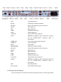
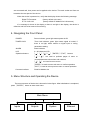
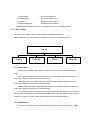
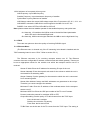
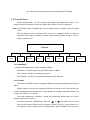
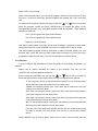
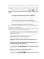
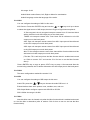
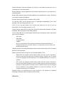
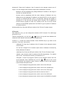
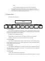
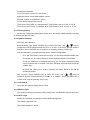
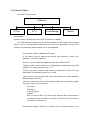
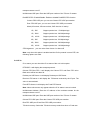
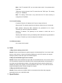
6PSDSC-IP-5000P Series PSDR-5000-42S2 CAM + IP PSDR-5000-30S2 CAM Multi-Format Professional HDTV Processor User Manual Ver. 2.3 Contents 1. Before Use the Device ............................................................................................................... 1 2. Introduction ................................................................................................................................. 2 3. Installation .................................................................................................................................. 3 3.1 Inspection .......................................................................................................................... 3 3.2 Operating Voltage ............................................................................................................. 3 3.3 The fuses........................................................................................................................... 3 3.4 Connecting Up the Device ................................................................................................ 3 3.5 Power On the Device ........................................................................................................ 4 4. Navigating the Front Panel ......................................................................................................... 5 5. Menu Structure and Operating the Device................................................................................. 5 5.1 Inputs Menu ...................................................................................................................... 6 5.1.1 Status Menu ............................................................................................................ 6 5.1.2 DVB-S2 Menu ......................................................................................................... 6 5.1.3 RSSI ........................................................................................................................ 7 5.1.4 Ethernet Menu ........................................................................................................ 7 5.2 Outputs Menu.................................................................................................................... 8 5.2.1 BISS Menu .............................................................................................................. 8 5.2.2 CI Menu .................................................................................................................. 8 5.2.3 Decoder .................................................................................................................. 9 5.2.4 ASI1 ...................................................................................................................... 11 5.2.5 ASI2 ...................................................................................................................... 11 5.2.6 SDI ........................................................................................................................ 11 5.2.7 Mux ....................................................................................................................... 11 5.2.8 Ethernet ................................................................................................................ 12 5.3 System Menu .................................................................................................................. 15 5.3.1 Local Setup ........................................................................................................... 15 5.3.2 Trap IP Addr.......................................................................................................... 15 5.3.3 Unit Name ............................................................................................................. 15 5.3.4 Properties.............................................................................................................. 15 5.3.5 Factory Setting ...................................................................................................... 16 5.3.6 Optional Function.................................................................................................. 16 5.3.7 LCD Switch ........................................................................................................... 16 5.3.8 Machine Type ....................................................................................................... 16 5.3.9 HTTP Login ........................................................................................................... 16 5.4 Ethernet Menu................................................................................................................. 17 5.4.1 IP Out .................................................................................................................... 17 5.4.2 IP In ....................................................................................................................... 18 -3- 5.4.3 Local IP setting ..................................................................................................... 19 5.4.4 Ethernet status ...................................................................................................... 19 6. FAQ .......................................................................................................................................... 19 7. Specification ............................................................................................................................. 19 8. Accessory List .......................................................................................................................... 21 9. IPTV Configuration Quick Guide .............................................................................................. 22 9.1 How to receive a multicast or unicast stream ................................................................. 22 9.2 How to set the Unicast/Multicast output.......................................................................... 23 1. Before Use the Device Thank you for purchasing the 6PSDSC-IP-5000Pseries. This User Manual is written for operators/users of the 6PSDSC-IP-5000PMulti-Format Professional HDTV Processor to assist in installation and operation. Please read this user manual carefully before installation and use of the device For Your Safety This equipment is provided with a protective earthing ground incorporated in the power cord. The main plug shall only be inserted in a socket outlet provided with a protective earth contact. Any interruption of the protective conductor, inside or outside the device, is likely to make the device dangerous. Do not remove the covers of this equipment. Hazardous voltages are present within this equipment and may be exposed if the covers are removed. Only NETKLA trained and approved service engineers are permitted to service this equipment. No operator serviceable parts inside. Refer servicing to NETKLA trained and approved service engineers. For the correct and safe use of the device, it is essential that both operating and servicing personnel follow generally accepted safety procedures in addition to the safety precautions specified in this manual. Whenever it is likely that safety protection is impaired, the device must be made in-operative and secured against unintended operation. The appropriate servicing authority must be informed. For example, safety is likely to be impaired if the device fails to perform the intended measurements or shows visible damage. WARNINGS The mounting environment should be relatively dust free, free of excessive vibration and the ambient temperature between 0 ℃ to 40 ℃. Relative humidity of 20% to 80% (non-condensed) is recommended. Avoid direct contact with water. Never place the equipment in direct sunlight. The outside of the equipment may be cleaned using a lightly dampened cloth. Do not use any cleaning liquids containing alcohol, methylated spirit or ammonia etc. For continued protection against fire hazard, replace line fused only with same type. Air intake for cooling is achieved via holes at the side of the device and the fans inside. The air flow should not be obstructed. Therefore, the device has to be placed on a flat surface, leaving some space at the sides of the device. When in operation, the internal temperature should not exceed the limit of 70 ℃. 2. Introduction As the latest version of NETKLA‟s flagship professional IRD, the 6PSDSC-IP-5000Pis full compliant with MPEG-2 (MP@ ML& MP@HL), H.264 and DVB-S2/S/-C/-T standards. With a wide choice of input options for all transmission mediums, the 6PSDSC-IP-5000Pprovides significant benefits and the maximum flexibility for professionals who wish to migrate their operations from MPEG-2 SD to H.264 HD. Equipped with 2 PCMCIA slots, it also supports various CA systems such as Irdeto, Conax, Viaccess, Cryptoworks, Mediaguard, and SECA, etc. With TS over IP output (Optional), user could convert DVB-S2/S/-C/-T programs into IP format. It can be monitored and set parameters easily with Ethernet management software. Moreover, it supports CVBS, YPbPr, BNC, SDI, HDMI, AES_EBU output interface. High transmission speed and low error rate give more valuable features to this model. With 19” rack, makes the receiver the best choice for your digital Headend System. Model List 5000P-10x Model No. Function x= 10/100M Base-T TSoIP Input/output GbE Input/output DVB-C Input DVB-T Input DVB-S2 Input C ○ T ○ S2 ○ HDMI Output Ethernet Remote Control ○: Optional DS3 ○ √ -5000P-30x C T S2 DS3 √ √ √ √ ○ ○ ○ ○ √ √ C ○ T ○ S2 ○ 5000P-44x DS3 ○ √ √ √ C T S2 DS3 √ √ √ √ ○ ○ ○ ○ √ √ √ √ DS3 Input CI slots*2 ASI TS Input/Output HD-SDI Output (Embedded Audio 2.0ch *2) RCA Analog Audio output * 2 pairs Balance Analog Audio output * 2 pairs AES/EBU Digital Audio Output *2 ports YPbPr Output 5000P-20x √ √ √ √ √ √ √ √ √ √ √ √ √ √ √ √ √ √ √ √ √ √ √ √ √ √ √ √ √ √ √ √ √ √ √ √ √: Standard Video Format Output port Resolution SDI port 576I25 ,480I29.97, 1080I25, 1080I29.97, 1080I30 576I25 ,480I29.97,480P60, 576P50, 720P50,720P59.94 720P60,1080I25, 1080I29.97, 1080I30 576I25 ,480i29.97,480P60, 576P50, 720P50,720P59.94 720P60,1080I25, 1080I29.97, 1080I30 576I25,480I29.97 HDMI port YPbPr port CVBS port 3. Installation 3.1 Inspection Open the packaging box, check if all appendixes are in the box according to the appendix list, and if the device has any visible damage, please contact the agent. 3.2 Operating Voltage Do not connect AC power until you have verified that the line voltage is correct and the proper fuses are installed. The device‟s power supply is fitted with a wide-ranging power supply. It is suitable for supply voltages of 100-240 Vac -10% +6% at 50/60 Hz nominal. Be sure the supply voltage is within the specified range. POWER REQUIREMENT Input voltage 90-250 Vrms auto select Frequency 47 to 63 Hz Power 50 VA max. / 30 VA typical. Current 110 V/0.27A or 240 V/0.125A typical 3.3 The fuses The recognized recommended fuses are size 5 by 20 mm, rate T 2.0A, 250 V (UL and IEC approved). The line fuse is housed in a small container besides the power connector on the rear panel. To check the fuse, insert the tip of a screwdriver in the slot at the middle of the container and pry gently to extend the fuse where there is a little tap and pull out the fuse gently. The fuse is attached to the line module and cannot be removed. 3.4 Connecting Up the Device Always use the specified cables supplied for signal integrity and compliance with EMC requirements. The rear panel is directly related to the input and output options fitted. Below figure shows a typical rear panel. TS/IP RS-232 ASI Out1 ASI1 In SDI1 Management ASI Out2 ASI2 In SDI2 CVBS YPbPr L-Audio-R1 Audio1 Tuner out Tuner in HDMI CVBS L-Audio-R2 Audio2 GND Switch Power Socket TS/IP IP input/output port RS-232 serial port for printing information ASI OUT1 Group1 ASI output port (one for back-up) ASI1 IN ASI1 input port SDI1 SDI1 output port CVBS CVBS BNC output port YPbPr YPbPr output port L-Audio-R1 Group1 RCA audio output port Audio1 AES/EBU and Balance Audio output port1 (need to use the RS232-to-XRL converting cable in accessories) TUNER OUT Tuner signal loop through output port TUNER IN Tuner signal input Switch Power switch MANAGEMENT LAN port for software update ASI OUT2 Group2 ASI output port (one for back-up) ASI2 IN ASI2 input port SDI2 SDI2 output port HDMI HDMI output port CVBS CVBS RCA output port L-Audio-R2 Group2 RCA audio output port AUDIO2 AES/EBU and Balance Audio output port2 (need to use the RS232-to-XRL converting cable in accessories) GND Grounding terminal Power Socket AC 90~250V 50-60Hz input 3.5 Power On the Device Be sure the device is mounted into the rack properly and firmly, and the signal cables are connected well, then power can be applied to the device. The main socket and fuse are located at the rear panel of the device. When the device is powered on, verify that the display shows the following message: Digital TV Processor (factory default unit-name) IP: 10.10.60.148 (factory default IP Address for LAN access) If no message is shown in the display or there is not light in the display, the device is defective and has to be returned for servicing. 4. Navigating the Front Panel POWER Power indicator, green light means power is OK TUNER LOCK Tuner lock indicator, green light means signal is locked; if there is no light, which means no signal input or wrong parameters setting. ALARM Alarm indicator LCD 2 × 20 character LCD Operation buttons 〔 〕〔 〕〔 〕〔 〕〔ENTER〕〔EXIT〕 buttons 〔 〕〔 〕 are used to up/down pages of menu or increase/decrease value when edit numbers 〔 〕〔 〕 are used to move cursor 〔ENTER〕is used to enter sub menu or confirm operation 〔EXIT〕is used to return previous menu or cancel operation Common Interface PCMCIA Module slot 5. Menu Structure and Operating the Device The menu structure of the device is showed in below figure. After initialization is completed, press 〔ENTER〕 button to enter main menu: Main Menu Inputs Outputs System Ethernet (1) Input Setup Set input parameters (2) Output Setup Set output parameters (3) System Set system parameters (4) Ethernet(optional) Set Ethernet parameters Note: Ethernet under Main Menu only appears if the unit is a Gigabit model. 5.1 Inputs Menu There are four options: Status, DVB-S2, RSSI and Ethernet (optional): Note: Ethernet under Inputs Menu only appears if the unit is a Megabit model. Inputs Status DVB-S2 RSSI Ethernet 5.1.1 Status Menu It contains four options, ASI1, ASI2, TUNER and IP IN, to show the status of signal input: ASI1: When signal from ASI1 input port is locked, it will display package format and code rate; if signal is not locked, it will show Unlock. ASI2: When signal from ASI2 input port is locked, it will display package format and code rate; if signal is not locked, it will show Unlock. TUNER: When signal from tuner input port is locked, it will display package format and code rate; if signal is not locked, it will show Unlock. IP IN: When signal from IP input port is locked, it will display package format and code rate; if signal is not locked, it will show Unlock.(Note: this option only appears when set the External Function as “IP IN”. Please refer to section 5.3.6 for setting method) 5.1.2 DVB-S2 Menu There are 6 options to set DVB-S2 parameters. After signal is locked, the TUNER LOCK indicator on front panel will turn green. LNB Frequency: Input LNB frequency Satellite Frequency: Input downstream frequency of satellite Symbol Rate: Input symbol rate of satellite LNB Voltage: select the correct LNB voltage output of the F-connector: Off, 13 V, 18 V. <A> LNB 22KHz: activate the LNB 22 kHz control signal to the LNB: On or Off. <B> DISQEC: Can select OFF/Port A/Port B/Port C/Port D Note: please contact the local satellite operator for the satellite frequency and symbol rate. <A> Normally, 13V switches the LNB to receive Vertical/Left hand polarization while 18V receive Horizontal/Right hand. <B> Normally, 22KHz control signal switches the LNB to receive high band if any. 5.1.3 RSSI There are two options to show the quality of receiving DVB-S2 signal. 5.1.4 Ethernet Menu (The Ethernet menu is showed only if the IP streaming in/out board is installed and the TS/IP streaming board is set to “IP IN”. Refer to section 5.3.6.) The Ethernet connector is for receiving transport stream over IP. The Ethernet connector has user-configurable IP address, network mask and default gateway. These must be set to appropriate values for the network over which the transport stream over IP is received. Stream IP Addr: Enter the IP address for streaming IP input of the unit. Stream Netmask: Enter the network sub mask for the subnet to which the unit is connected for IP streaming traffic. Stream Gateway: Set the gateway for the network to which the unit is connected for IP streaming traffic. Stream Mac Address: factory-set MAC addresses are guaranteed to be unique. Therefore you cannot configure the address. Multicast IP Addr: Enter the IP address of the multicast stream for the transport stream over IP. Multicase UDP Port: Enter the UDP port number of the TS over IP stream. Protocol: select the protocol for multicast: UDP or RTP. Output Smoothing: set the quality of TS which comes from the TS/IP input. Auto: the bit rate is variable. Disable: the unit let the TS pass by. Fixed Rate: the bit rate is fixed. TS Bit Rate: set the bit rate of the TS comes from the TS/IP input. The setting is only valid when the output smoothing is configured as Fixed Rate. 5.2 Outputs Menu Under Outputs Menu, you can monitor and configure the parameters of the CI, AV decoder, ASI out, ASI2/SDI out, Mux (A), BISS, SDI out and TS over IP output (B). Note: (A) The Mux menu is showed only if the functional block is enabled. Refer to section 5.3.6. (B) The Ethernet menu is showed only if the unit is a Megabit model, on which IP streaming in/out board is installed and the TS/IP streaming board is set to “IP Out”. Refer to section 5.3.6. Outputs BISS CI Decoder ASI1 ASI2 SDI Ethernet 5.2.1 BISS Menu It includes Biss Mode, Biss 1 Setup and Biss E Setup Biss Mode:Set Biss mode, can select OFF, Biss E or Biss 1 Biss 1 Setup:set Biss 1, password is required Biss E Setup:set Biss E, ID number and password are required 5.2.2 CI Menu There are two PCMCIA slots for inserting CAM for de-encrypting program from the input signal. Before setting CI, ensure the signal from ASI input is locked or the Tuner locks on the correct Transponder (this depends on in which signal the encrypted program carried). The „Tuner Lock‟ LED will 'on' in green. There are 3 submenus: „CI Source‟, „Setup‟ and „CAM name‟ which allow you to set or select the parameters of the CI. CI Source: press the <ENTER>-key, then use < > or < >-key select Tuner or ASI1 input or ASI2 input or TS/IP input (only when the TS/IP is set “IP In”, refer section 5.2.7 for details) to set the signal source of descrambling, press <ENTER>-key to save or Mux press <EXIT>-key to scrap. Setup: under this sub menu, you can see all program names from the source of CI that was set in „CI Source‟ previously. All free programs are marked with „Free‟ in the first row. To select which program to be de-encrypted, press the < > or < >-key to roll up and down the program names and press <ENTER>-key to change the status of the corresponding program (only encrypted program could be selected). Three different statuses could be set: Slot 1 (de-encrypted with upper CAM inserted) Slot 2 (de-encrypted with lower CAM inserted) Bypass (no de-encryption). The status will be shown in the first row on the LCD display. Confirm this setup when leaving this sub menu, press <ENTER>-key to save or press <EXIT>-key to scrap. The de-encrypted program could be delivered to other functional blocks, like A/V decoder, ASI1, ASI2, SDI, Mux and TS/IP output (refer to section 5.2.3~5.2.8 for more). CAM name: under this sub menu, you can see the names of CAM modules. 5.2.3 Decoder You can configure the parameters of Video and Audio of the program decoded by AV decoder. Status: OK or Alarms indicates the status of the decoder. You can use the <ENTER>-key to check detailed information. Source: Press the <ENTER>-key and use the < > or < >-key to roll up or down to select the signal source of ASI output, there are 5 type of signal source optional: CI De-encrypted: the de-encrypted transport stream from CI functional block will be delivered to the ASI output port on the back panel. TUNER: the transport stream from Tuner block will be delivered to the ASI output port on the back panel. ASI1 Input: the transport stream comes from ASI1 input port will be delivered to the ASI1 output port on the back panel. ASI2 Input: the transport stream comes from ASI2 input port will be delivered to the ASI2 output port on the back panel. Mux TS: the transport stream comes from internal Mux functional block will be delivered to the ASI output port on the back panel. (The Mux TS is valid only when the Mux function block is enabled and turned on. Refer to section 5.2.7 and section 5.3.6 for how to set the Mux function block.) Press <ENTER>-key to save or press <EXIT>-key to scrap. A few seconds after the source being selected, the TS will be delivered to the ASI output port on the back panel. Program: under this sub menu, you will see all program names detected by DCH-5000P. The programs could be coming from ASI input, Tuner, TS/IP input, the internal CI de-encryption block, BISS De-encryption block or MUX TS. Use the < to roll up or down between the program names, and use < >-and < > or < >-key >-key to switch among input sources, where a number in front of the program name indicates the input source: 0-xxxxx displays the program name, which comes from ASI input. 1-xxxxx displays the program name, which comes from TUNER input. 2-xxxxx displays the program name, which comes from TS/IP input 3-xxxxx displays the program name which comes from the CI. 4-xxxxx displays the program name, which comes from ASI2 input. 5-xxxxx displays the program name, which comes from BISS De-encrypted input. 6-xxxxx displays the program name, which comes from MUX TS. A few seconds after the program being selected, the A/V signal will be delivered to the related connectors on the back panel. Video: You can configure the video parameters of programs in this submenu. Press the <ENTER>-key to confirm or press the <EXIT>-key to cancel. Video Standard: you can select Auto/1920x1080i 60/1920x1080i 50/1280x720p 60/1280x720p 50/720x480p 60/720x576p 50/525x480i 60/625x576i 50 for the composite video output. Screen: select the screen mode: 4:3 Full, 16:9 Full or 4:3 Letterbox. DVB Subtitle Lang: select the language of DVB Subtitle. EBU Subtitle Lang: select the language of EBU Subtitle. Subtitle Priority: configure the priority of Subtitle; choose whether DVB or EBU should be first. Fail Mode:choose which kind of picture will appear when signal is fail. You can select Black Screen or No Sync or Still Picture Audio: You can configure the audio settings in the submenu. Audio1 Level: use the < >< >< >< >-keys to modify the audio1 level within this range: 0~99. Audio1 Mode: select Stereo, Left, Right or Mono for soundtracks. Audio1 Language: select the language of the audio. Audio2 Level: use the < >< >< >< >-keys to modify the audio2 level within this range: 0~99. Audio2 Mode: select Stereo, Left, Right or Mono for soundtracks. Audio2 Language: select the language of the audio. 5.2.4 ASI1 You can configure the settings of ASI1 in this menu. ASI1 Source: Press the <ENTER>-key and use the < > or < >-key to roll up or down to select the signal source of ASI output, there are 5 type of signal source optional: CI De-encrypted: the de-encrypted transport stream from CI functional block will be delivered to the ASI output port on the back panel. TUNER: the transport stream from Tuner block will be delivered to the ASI output port on the back panel. ASI1 Input: the transport stream comes from ASI1 input port will be delivered to the ASI1 output port on the back panel. ASI2 Input: the transport stream comes from ASI2 input port will be delivered to the ASI2 output port on the back panel. Mux TS: the transport stream comes from internal Mux functional block will be delivered to the ASI output port on the back panel. (The Mux TS is valid only when the Mux function block is enabled and turned on. Refer to section 5.2.7 and section 5.3.6 for how to set the Mux function block.) Press <ENTER>-key to save or press <EXIT>-key to scrap. A few seconds after the source being selected, the TS will be delivered to the ASI output port on the back panel. 5.2.5 ASI2 The same configuration method like section 5.2.4 5.2.6 SDI You can configure the settings of SDI output in this menu. Audio PID: press the < >< >-keys to choose the audio PID from 1~4. Embed Audios: there are 4 options: none, one&two, two, and one. SDI Output Mode: configure output mode HD-SDI or SD-SDI SDI H Offset: the range is 0~999 5.2.7 Mux Note this Mux menu is showed only when the Mux function block is enabled and turned on. And the Mux is alternative (refer to section 5.3.6 for how to turn on and set the Mux function block). Mux Switch: the internal multiplexer could be switched On/Off. The default value is „off‟. To activate the re-Multiplexing function, you should turn on this Mux functional block. Bit Rate: should be set to a specified value that doesn‟t exceed the Maximum physical limit of the output medium. For example, to deliver the multiplexed TS to an 8MHz DVB 256QAM modulator, it should not exceed 55000Kb/s, otherwise overflow occurs. TS ID: you can configure the TS ID to mark the multiplexed TS. Default value is 1. Program List: press the <ENTER>-key to enter „Mux List‟ sub-menu. It shows all programs detected by DCH-5000P. The programs could be come from ASI input, Tuner, TS/IP input or the internal CI de-encryption block. Use < program names, and use < > < >< >-keys to roll up the >-keys to switch among input sources, where a number in front of the program name indicates the input source: 0-xxxxx displays the program name, which comes from ASI input. 1-xxxxx displays the program name, which comes from TUNER input. 2-xxxxx displays the program name, which comes from TS/IP input 3-xxxxx displays the program name which comes from the CI. 4-xxxxx displays the program name, which comes from ASI2 input. 5-xxxxx displays the program name, which comes from BISS De-encrypted input. On „Program List‟ sub-menu, on the first row, all encrypted programs are labeled with a „$‟ sign. All programs that are being selected to be re-multiplexed are labeled as „Pass‟, otherwise, the un-selected programs are labeled as „Fobrid‟. Use <ENTER>-key to selected or un-selected the program being shown. When leaving the „Program List‟ sub-menu, a new menu will be shown „Confirm changed?‟ Press <ENTER>-key to validate all programs just be selected to be multiplexed or to scrap by pressing <EXIT>-key. After a few seconds, the multiplexed TS will be generated and delivered to the specified destination(s). 5.2.8 Ethernet (Note The Ethernet menu is showed only if the unit is a Megabit model, on which IP streaming in/out board is installed and the TS/IP streaming board is set to “IP Out”. Refer to section 5.3.6) The TS/IP Ethernet connector could also be configured as the output of the transport stream over IP. The parameters listed below must be set to appropriate values for the network over which the transport stream over IP is broadcasted. Stream IP Addr: Enter the IP address for streaming IP output of the unit. Stream Netmask: Enter the network sub mask for the subnet to which the unit is connected for IP streaming traffic. Stream Gateway: Set the gateway for the network to which the unit is connected for IP streaming traffic. Stream Mac Address: factory-set MAC addresses are guaranteed to unique. Therefore you cannot configure the address. Protocol: select the protocol for multicast: UDP or RTP. TS Pkts Per UDP: set the number of the TS packages encapsulated in one UDP package. The valid range goes from 1 to 7. Time To Live: set the number of the routers over which the TS over IP can be transmitted. The valid range goes from 1 to 5. Type of Service: select the type of service. There are: Normal, Min Monetary Cost, Max Reliability, Max Throughput or Min Delay optional. Source: select the source of the transport stream over IP streaming output. There are 5 type of source optional: ASI1 Input ASI2 Input CI De-encrypted TUNER Mux TS (note the Mux TS is showed only when the Mux function block is enabled and turned on. Refer to section 5.2.7 and section 5.3.6 for how to set the Mux function block) After the operation, the selected transport stream will be delivered to the TS / IP function block for further operation. Mode: select the mode of IP stream, you can select DVB or IPTV. DVB mode: the transport stream which comes from the ‘source’ selected in previous step will be packed into IP Stream directly. Therefore the IP stream carries all programs and be delivered to the specified Multicast or Unicast IP address. IPTV mode: the transport stream which comes from the ‘source’ selected in previous step will be de-Muxed to several single programs, and each program is packed into one IP stream. Therefore each IP stream carries only one program and be delivered to the specified Multicast or Unicast IP address. You can configure maximum 6 IPTV channels. Multicast Setup: use <ENTER>-key to enter sub-menu. The sub-menu is different according to different „mode‟ selected in previous step. DVB mode Multicast IP: Enter the IP address of the IP stream for the transport stream over IP output. You can configure the IP stream output mode in Multicast or Unicast. Multicast could be established by setting Multicast IP address in the range of 224.0.0.0 to 239.255.255.255. Unicast could be established with the same settings of Multicast, the only differences are the Multicast IP address, and should NOT be in the range of 224.0.0.0 to 239.255.255.255, which is for Multicast. Although the display is 'Multicast IP' on the first row, the stream itself is Unicast. The IP address of receiver device (maybe PC with VLC) needed to be set to as the unicast address on DCH-5000P, please don't use DHCP to get a dynamic IP address for receiver device. Multicast UDP Port: Enter the UDP port number of the TS over IP stream output. IPTV mode Max Channels (<=6): you can configure the number of IPTV channel. The valid range goes from 0 to 6. After the configuration, you can use < >< >-keys to roll up and down between the channels. Each channel could be configured independently. Channel x: „x‟ means the channel number. Press <ENTER>-key to go down to the sub-menu. There are 4 sub-menus: x-Multicast IP: Enter the IP address of the IP stream for the transport stream over IP output. You can also configure the IP stream output mode in Multicast or Unicast by setting Multicast IP address. x-Multicast Port: Enter the UDP port number of the TS over IP stream output. x-Switch: each channel could be switched On/Off independently. The default value is „off‟. To activate the channel, you should turn on. x-Program: it shows all programs carried by the transport stream from the source selected. Press <ENTER>-key and use < >< >-keys to roll up and down between the program names, where a number in front of the program name indicates the input source: 0-xxxxx displays the program name, which comes from ASI input. 1-xxxxx displays the program name, which comes from TUNER input. 2-xxxxx displays the program name, which comes from TS/IP input 3-xxxxx displays the program name which comes from the CI. 4-xxxxx displays the program name, which comes from ASI2 input. 5-xxxxx displays the program name, which comes from BISS De-encrypted input. 6-xxxxx displays the program name, which comes from MUX TS. All encrypted programs are labeled with a „$‟ sign on the first row. Press <ENTER>-key to the program just be selected to be delivered to the specified IPTV channel or to scrap by pressing <EXIT>-key. 5.3 System Menu There are seven sub-menus: System Local Setup Trap IP Unit Properties Name Factory Optional LCD Machine Settings Function Switch Type 5.3.1 Local Setup Each 6PSDSC-IP-5000Phas an IP address, a network sub mask and a gateway. These must be set to an appropriate value for the network over which the unit can be accessed by the remote control system such as the HDMS. IP Address: The IP address for the unit. Network Mask: The network mask for the subnet to which the unit is connected. Gateway: The gateway for the network to which this unit is connected. 5.3.2 Trap IP Addr The 6PSDSC-IP-5000Pprovides a Monitor Center IP address. You can set this to be the same IP address of the Monitor Center, which is typically a PC in order to allow the device to send messages to the monitor center. 5.3.3 Unit Name The 6PSDSC-IP-5000Pallows you to edit the unit name which is displayed on the front panel LCD. Default name is „Digital TV Processor”. The unit name should not be longer than 20 characters in ASCII format. 5.3.4 Properties Version: show software version of this device MAC Address: Factory-set MAC address which is guaranteed to be unique. You cannot HTTP Login configure this address. Linux OS version: show Linux OS version ARM SW version: show ARM software version Decoder version: show Decoder version FPGA version: show FPGA version TS/IP IN (or OUT) NIOS: it‟s changed when TS/IP board is set to “IP Out” or “IP IN”. TS/IP IN (or OUT) FPGA: it‟s changed when TS/IP board is set to “IP Out” or “IP IN”. 5.3.5 Factory Setting All the user configurable parameters will be set to the factory default settings, including IP address and the unit name. 5.3.6 Optional Function There are two submenus: External Board Type: Press <ENTER>-key to active the menu, use < >< >-keys to configure the TS/IP functional block as „IP In‟ or „IP Out‟ or „No Exist‟, and the option is exclusive. Press <ENTER>-key to confirm or to scrap by pressing <EXIT>-key. After the operation, you need reboot the unit to valid the configuration. IP In: the TS/IP port is configured as input, you can feed transport stream over IP into the unit. The menu „Ethernet‟ will be showed under the inputs menu. IP Out: the TS/IP port is configured as output, you can set the transport stream over IP output to the IP network. The menu „Ethernet‟ will be showed under the outputs menu. No Exist: the TS/IP port is invalid. Therefore the menu „Ethernet‟ will not be showed anywhere. Mux Function: Press <ENTER>-key to active the menu, use < > < >-keys to configure the Mux functional block as „Enable‟ or or „Disable‟. Press <ENTER>-key to confirm or to scrap by pressing <EXIT>-key. 5.3.7 LCD Switch There are two options: Always On and Time 5.3.8 Machine Type This setting is reserved for factory-setting, and you are not allowed to access this menu. 5.3.9 HTTP Login Modify the username and password for the WEB management. The default username: root The default password: 12345 5.4 Ethernet Menu There are four sub menus. Ethernet IP Out IP In Local setting Status 5.4.1 IP Out (Note this menu is showed only when the IP Out switch is enabled.) The TS/IP Ethernet connector could also be configured as the output of the transport stream over IP. The parameters listed below must be set to appropriate values for the network over which the transport stream over IP is broadcasted. IP Out switch: enable or disable the IP output. IP Out status: show IP packets per second, UDP packets/s, Column FEC packets/s, Row FEC packets/s Protocol : you can select the transport protocol from UDP and RTP. TS pkts per UDP: set the number of the TS packages encapsulated in one UDP package. The valid range goes from 1 to 7. Time to Live: set the number of the routers over which the TS over IP can be transmitted. The valid range goes from 1 to 255. Type of Service: you can select from normal, Min monetary cost, Max reliabliltity, Max throughput, Min delay TS source: select the source of the transport stream over IP streaming output. There are 5 type of source optional: ASI1 Input ASI2 Input CI De-encrypted TUNER Mux TS (note the Mux TS is showed only when the Mux function block is enabled and turned on. Refer to section 5.2.7 and section 5.3.6 for how to set the Mux function block) Uni/Multicast Address: Enter the IP address of the multicast stream for the transport stream over IP. Uni/Multicast UDP port: Enter the UDP port number of the TS over IP stream. ProMPEG FEC: Enable/Disable: Enable or disable ProMPEG FEC function. Column FEC UDP port: you can set Column FEC UDP port number Row FEC UDP port: you can set Column FEC UDP port number Mode(1D:column, 2D:row+column, 5X5: the size of matrix) 1D,5X5 Support packet loss : 5/1000package 1D,5X20 Support packet loss :20/1000package 1D,10X10 Support packet loss :10/1000package 2D,5X5 Support packet loss :5/1000package 2D,5X20 Support packet loss :20/1000package 2D,10X10 Support packet loss :10/1000package FEC Alignment: you can select from Annex A or Annex B Note: only when this option is enabled and the IP Out protocol is set to RTP, the following options are valid. 5.4.2 IP In IP in status: you can check the IP In status of the unit in this option. RTP/UDP: it will display the transport protocol. Column FEC;Row FEC: it will display the Column FEC and Row FEC value. Both value will be less than 20. Packets per UDP frame: it will display Packets per UDP frame. Received TS frames: it will display the TS frames received by the IP port. The value is accumulated. Fixed RTP frames: it will display the Fixed RTP frames. Note: Above sub-menus only appear when the IP in status is set as Locked. Uni/Multicast Address: Enter the IP address of the multicast stream for the transport stream over IP. Uni/Multicast UDP port: Enter the UDP port number of the TS over IP stream Column FEC UDP port: Enter the Column FEC UDP port number Row FEC UDP port: Enter Row FEC UDP port number TS clock recovery: Select the TS clock recovery mode from Auto or Fixed rate. Note: If the TS contains PCR, you can select Auto mode. If not, please select Fixed rate. TS Bit rate: set the bit rate of the TS comes from the TS/IP input. The setting range is 0—100Mbits/s. Note: The setting TS Bit rate is only valid when the TS clock recovery is configured as Fixed Rate. 5.4.3 Local IP setting IP address: Enter the IP address for IP input or output of the unit. Subnet mask: The network mask for the subnet to which the unit is connected. MAC address: factory-set MAC addresses are guaranteed to be unique. Therefore you cannot configure the address. Gateway IP address: The gateway for the network to which this unit is connected. Gateway MAC address: factory-set Gateway MAC addresses are guaranteed to be unique. Therefore you cannot configure the address. 5.4.4 Ethernet status Link: shows the link speed 6. FAQ 1. Why is there nothing in the LCD? Answer: Please check whether the power supply is connected well first. If not, insert it well and turn on the device. If there is still nothing displayed on the LCD, then the unit may be damaged, please contact the agent for technical support. 2. Why can the DVB-S2 signal not be locked? Answer: Please ensure whether the input cable in connected well first. If not, insert it well. If it is connected well, please check whether all the necessary parameters are set properly. If not, please set the parameters properly. If the signal still cannot be locked, please check whether the quality of the signal is out of the threshold of the Tuner. If not, then the device might be damaged, please contact the agent for support. 3. Why can the ASI not be locked? Answer: Please make sure the BNC cable is connected well and there are programs transmitted to the unit via the BNC cable. 7. Specification Input DVB-S2 QPSK/8PSK Demodulation Input frequency range 950~2150MHz Input level -65~-25dBm Input impedance 75Ω Connector F Connector Symbol rate 5~45Msps for QPSK; 10~31Msps for 8PSK Rolling off factor 0.35 for QPSK; 0.35, 0.25, 0.2 for DVB-S2 Punctured rates DVB-S2 QPSK: 1/2,3/5,2/3,3/4,4/5,5/6,8/9,8/10 DVB-S2 8PSK: 3/5,2/3,3/4,5/6,8/9,9/10 DVB-S: 1/2,2/3,3/4,5/6,6/7,7/8 LNB Level 0, 13V, 18V 0/22K 0/22K DiSEqC DiSEqC 1.0 DVB-C QAM Demodulation Tuner Input symbol rate 1~7Mbps(PAL) or 1~6Mbps(NTSC) Demodulation 16/32/64/128/256 QAM Tuner Bandwidth 6MHz or 7MHz or 8MHz Input frequency range 50~860MHz Digital signal Input level -15~15dBmV Input connector IEC Female (7/8MHz) or F Female (6MHz) Input impedance 75Ω DVB-T COFDM Demodulation Constellation QPSK, 16-QAM, 64-QAM Tuner bandwidth 6MHz/7MHz/8MHz FFT mode 2K/8K Guard interval 1/4, 1/8, 1/16, 1/32, off FEC code rate 1/2, 2/3, 3/4, 5/6, 7/8 Input frequency rate 470-862MHz(8MHz); 174-230MHz(7MHz) Digital signal Input level -20~-70dBmV Input connector IEC Female (7/8MHz) or F Female (6MHz) Input Input impedance 75Ω Input connector BNC Female Input impedance 75Ω Max input code rate 44.736Mbits/s DS3 Input Format Unframed Framing according to G.804 / G.752 (DS3) Output DS3 loop through output Connector 75Ω, BNC female Max. output code rate 44.736Mbits/s Format Unframed Framing according to G.804 / G.752 (DS3) TS over IP Output Connector RJ45 10/100Base-T Max. output code rate 70Mbits/s UDP/RTP Multicast or Unicast Multicast control protocol IGMPV2 I/O Interface Tuner input/loop through 1× Input, 1×loop through output Power supply socket 3 pin inputs RS-232 1×9-pin D-sub male(for software update, Max Data Rate is 115200bps) TS/IP TS over IP input/output (optional) Management Network management system, allowing parameter setting and software upgrade ASI input 2 x BNC Female ASI output 4 x BNC Female SDI output 2 x BNC Female, supports HD-SDI/SD-SDI, (one for back-up) optional HDMI output 1(optional) YPbPr output 1 CVBS output 1×RCA, 1×BNC Female AES/EBU 2 x 9 pins D-type connector (optional) Power supply AC 90V~250V 50Hz/60Hz Net weight 5Kg Dimensions 483x255x44mm Operating temperature 0~45℃ Storage temperature 20~70℃ General 8. Accessory List 5000P-xx 1pc CD 1pc User Manual 1pc Power Cord 1pc RCA A/V Cable 1pc BNC Cable 1pc RS232-to-XRL cable 2pcs 9. IPTV Configuration Quick Guide First of all, make sure that your unit is equipped with IP hardware board. If not, please contact your agent for information. 9.1 How to receive a multicast or unicast stream Normally, the 5000P is set to IP Output by the factory. To set the 5000P to IP input mode, please follow the procedure below: 1. Only on the front panel is accessible, go to Main Menu System Optional function External board type IP in 2. Switch off the unit, and then switch it on again. Then the unit will become IP in, and the FACTORY DEFAULT setting will not change this IP direction. And at the same time, the menu structure on front panel & HDMS (the PC management software) will be changed accordingly. To receive a multicast/unicast stream: 1. Go to the Main menu Inputs Ethernet 2. Set the IP address & parameters for the IP hardware board, Stream IP addr enter the IP address for this IP hardware board (should be the same network section of the Stream Gateway, this depends on the characteristic of the gateway) Stream Netmask enter the network submask for this IP hardware board Stream Gateway enter the Gateway address for this IP hardware board Stream MAC addr Show the MAC address of this IP hardware board, read only. 3. Set the parameters for the incoming IP stream. On the same sub menu: Multicast IP addr enter the multicast IP address for the incoming stream (for the addresses inside 224.0.0.1 to 239.255.255.255 are belonging to multicast, for others else are belonging to unicast, the 5000P will identify it automatically) Multicast UDP port enter the port number of the incoming stream Protocol enter the protocol of the incoming stream, 5000P supports UDP and RTP. Output Smoothing Clock recover method from IP incoming stream, MUST set to Auto (both Auto & Fixed rate are for experimental test only). TS Bit Rate set to the bit rate of incoming stream in experimental test, this value will be ignored by 5000P if “Output Smoothing = Auto” in previous step. 4. After previous steps, 5000P will capture the incoming IP stream immediately. Normally it takes 30-60 seconds to lock the stream. You can go to the Main menu inputs Status IP IN to check the bit rate of incoming stream. 5. Finally, if user wants to watch TV decoded from IP incoming stream on the output of 5000P, don‟t forget to set the decoder portion of 5000P to select IP as the program source. 9.2 How to set the Unicast/Multicast output If the IP hardware board is configured as IP Input, please follow below procedure to change it to IP output: 1. Only on the front panel is accessible, go to Main Menu System Optional function External board type IP Out 2. Switch off the unit, and then switch it on again. Then the unit will become IP Out, and the FACTORY DEFAULT setting will not change this IP direction. And at the same time, the menu structure on front panel & HDMS (the PC management software) will be changed accordingly. To set Unicast/Multicast output, please follow the procedure below: 1. Go to the Main menu Outputs Ethernet 2. Set the IP address & parameters for the IP hardware board: Stream IP addr enter the IP address for this IP hardware board (should be the same network section of the Stream Gateway, this depends on the characteristic of the gateway) Stream Netmask enter the network submask for this IP hardware board Stream Gateway enter the Gateway address for this IP hardware board Stream MAC addr Show the MAC address of this IP hardware board, read only. 3. Set the universal parameters for the output IP stream. On the same sub menu: Gate MAC Address here the MAC address must be set as the as the MAC address of the Gateway where 5000P is located. Protocol enter the protocol of the output stream, 5000P supports UDP and RTP. TS Pkts Per UDP set the quantity of TS packages that will be carried IP package. The range goes from 1 ~ 7 Time to Live set the TTL for the output IP package. Type of Service set the type of service for the output IP stream Source set the wanted stream output via IP. Mode Set the IP output mode as IPTV mode or DVB mode. 4. If the mode is set to be DVB mode, please follow below procedure „DVB mode‟. If the mode is set to be IPTV mode, please go to procedure „IPTV mode‟ directly. DVB mode: Uni/Multicast Setup set the address and port parameters for the IP stream. Press Enter to go to the submenu. As below: Multicast IP enter the multicast IP address for the output stream (for the addresses inside 224.0.0.1 to 239.255.255.255 are belonging to multicast, for others else are belonging to unicast). Multicast UDP Port enter the port number of the output stream. Target Mac Addr set the MAC Address of the receiving device. The parameter will be used only when the receiving device is located under the same gateway. The parameter will be ignored by 5000P if the receiving device is located under other remote network or under different gateway. IPTV mode: Uni/Multicast Setup Press Enter to go to the submenu. As below: Max Channels set the quantity of multicast/unicast channels. Channel 0 set the private parameters for Multicast / Unitcast channel 0. Press Enter to go to the submenu. 0-Uni/Multicast IP enter the multicast IP address for the output stream (for the addresses inside 224.0.0.1 to 239.255.255.255 are belonging to multicast, for others else are belonging to unicast). 0-Uni/Multicast Port enter the port number of the output stream. 0-Target MAC address set the MAC Address of the receiving device. The parameter will be used only when the receiving device is located under the same gateway. The parameter will be ignored by 5000P if the receiving device is located under other remote network or under different gateway. 0-Switch turn on/off channel 0. 0-Program select the programs that want to be outputted via channel 0. For other channels, please refer to IPTV mode settings.