1
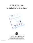
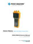
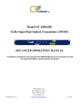
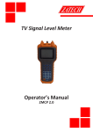
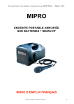
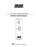
CVT 1stereo 1ub/2ub/3ub/uhf - II
Installation Instructions
The Channel Vision Multi-Room Video Modulator
makes it easy to map any three audio/video sources
to any unused channels on your television set(s).
Watching your security cameras, laser disk, video
tape, or any other video signal becomes as easy as
switching channels with your remote.
You can even map your stereo system to an unused
TV channel to pipe music to any room on your TV
"network"!
Please note: Some TV tuners need a video input to
achieve audio output.
Because the CVT Modulator merges these
additional inputs into your existing TV signal
"ahead of" your television sets the new channels will
be available at every TV hooked up to your coax
cable.
234 FISCHER AVENUE l COSTA MESA, CA 92626
(714) 424-6500 l (800) 840-0288 l (714) 424-6510 FAX
http://www.channelvision.com l E-Mail: [email protected]
© 2001, Channel Vision
Channel Vision
!
CAUTION
CVT1ub/uhf-II, CVT1stereo-II,
CVT2ub/uhf-II, CVT3ub/uhf
Tested To Comply
With FCC Stan-
RISK OF ELECTRIC SHOCK
FOR HOME OR OFFICE USE
DO NOT OPEN
CAUTION: TO REDUCE THE RISK OF ELECTRIC SHOCK,
DO NOT REMOVE COVER.
PROPER VENTILATION REQUIRED.
NO USER-SERVICEABLE PARTS INSIDE.
REFER SERVICING TO QUALIFIED SERVICE PERSONAL.
Note: This equipment has been tested and found to comply
with the limits for a Class B digital device, pursuant to
part 15 of the FCC Rules. These limits are designed to
provide reasonable protection against harmful interference
in a residential installation. This equipment generates,
uses and can radiate radio frequency energy and, if not
installed and used in accordance with the instructions, may
cause harmful interference to radio communications.
However, there is no guarantee that interference will not
occur in a particular installation. If this equipment does
cause harmful interference to radio or television reception,
which can be determined by turning the equipment off and
on, the user is encouraged to try and correct the interference by one or more of the following measures:
Products to be installed by certified dealers only.
•
•
Certification Requirements: Must be professional installing dealer, pass
•
certification test and familiar with TV and antenna systems. Call 800/840-
•
0288 for Channel Vision Training Manual and certification test.
Reorient or relocate the receiving antenna.
Increase the separation between the equipment and receiver.
Connect the equipment into an outlet a circuit different
from that to which the receiver is connected
Consult the dealer or an experienced radio/TV technician
for help.
Basic Installation Instructions
FCC Regulations – the Cable TV Act
“Cable home wiring” is the cable wiring located inside a Cable TV subscriber’s
home or apartment that has been installed by a cable operator or its contractor. It
does not include such items as amplifiers, converters, decoder boxes or remote control units.
After a subscriber voluntarily terminates cable service, the cable operator may take
one of two action:
1. Leave the home wiring in place.
2. Notify the consumer that it will remove the wiring unless the consumer
purchases it from the cable operator on a per-foot replacement cost basis.
If the wiring was previously transferred or sold to the subscriber, the subscriber owns
it; and the cable company cannot remove it or restrict its use, regardless of the reason
for service termination.
If the subscriber does not already own the wiring and declines to purchase it from the
cable operator, the cable operator may remove the home wiring within 30 days of the
subscriber’s refusal. The cable company must remove the wiring at no charge to the
subscriber, and must pay the cost of any damage caused by removing the wiring.
To leave the wiring inside and remove the wiring outside a subscriber’s home, a
cable operator may, for single unit dwellings, sever the cable approximately 12
inches outside the point where the cable enters the outside wall of the subscriber’s
home.
For multiple unit dwellings, the cable operator may sever the wire approximately 12
inches outside the point where the cable enters the subscriber’s individual dwelling
unit, except in cases of “loop-through” or other similar series wire configurations that
are not covered by the home wiring rules.
If the cable company fails to remove the wiring within 30 days of the subscriber’s
refusal to purchase it, the cable operator forfeits its right to the wiring and may not
remove it or restrict its use at any later time.
A cable operator will not be held responsible for any signal leakage that occurs from
the home wiring once the cable operator ceases providing service over that wiring.
The Channel Vision Multi-Room Video CVT Modulator is easy to hook-up.
Just connect your video sources to the CVT Modulator as you would
connect them directly to your TV's "video in."
Determine what channels you want to map your video sources to, then, with
the power off, use the DIP Switch Settings Table to set the dip switches on
the back of the CVT to provide that channel selection range.
Confirm that the video sources you're going to hook up are sending good
signals. Attach them to the video and audio inputs on the back of the CVT
Modulator. Connect the RF output on the CVT Modulator to one input of
the supplied combiner and your existing cable/TV/antenna cable to the
other. Finally, connect the output of the combiner to your TV network and
plug the CVT Modulator in to the wall outlet.
Turn your TV on, then press SELECT on the CVT Modulator to cycle the
front display to the A, B, or C input. Then select the channel you wish to
set (the light on the front panel shows the currently selected input, and the
channel display shows the channel to which that source is currently being
sent). Change the channel by holding the SELECT down for two seconds
until the A/B/C light on the front panel blinks. This puts the CVT
Modulator in channel-change mode.
Press the UP or DOWN buttons on the CVT Modulator to adjust the
channel number as desired. When satisfied, press SELECT again to exit
channel-change mode (the CVT Modulator will automatically exit channelchange mode after 5 seconds of inactivity). Repeat for your other two input
sources (if applicable). Leave a channel free between your selected
channels to avoid frequency interference. For example, mapping to
channels 32-34-36 is fine, but 32-33-34 is not.
We suggest that you connect a RF distribution amplifier to your cable/
antenna signal (see set up diagram on next page) so you can easily balance
the signal strength of that signal and the CVT Modulator signal. Extreme
CVT 3ub/uhf Basic Setup
differences in signal strength may cause interference.
That's all there is to it. The information on the following pages will help you
configure more sophisticated home "networks" but is not necessary for basic
setups.
Source A/V Inputs
Cable or
Antenna
System Design Considerations
Sophisticated home "networks" involving many TV sets are feasible with the
CVT Modulator, but care must be taken to design an optimum TV signal
distribution system.
CVT 3UB/UHF
TV sets are designed for signals around 10dBmV. Signals substantially below
0dBmV result in weak, fuzzy, snowy pictures. FCC states 0dBmV minimum at
TV and 15dBmV maximum
Channel Vision
MULTI ROOM VIDEO TECHNOLOGY
CVT - 15PIA
Signals above 10dBmV may overdrive older TV sets which don't have modern
automatic gain controls (which can handle signals to 40dBmV). An inline
attenuator (pad) can be used to reduce these signals, and to balance radically
different signal strengths at all your TV's.
HS-2
Signal strength decreases with coax cable length, and through connectors,
splitters, and combiners, so it's important to determine how much cable and
what in-line devices you'll be using, and adjust your input signal levels with
amplifiers at the front end or in-line on your network to compensate for the line
losses. The charts on the back of these instructions will help you calculate
likely losses through coax cable runs and splitters.
In-line amps are powered through the coax cable and can be used to achieve
modest signal strength gains; more powerful, a/c powered amps offer more
amplification (and usually adjustable gain and tilt too). Your system should
provide 10dBmV to every TV (maximum is 15.5dBmV, per the FCC).
HS-3
Setting Up TV Channel Range
Example of Dip Switch Settings
Switch Band/Channels
**
Cable (59-86
see note )
below
Reverse isolation is used to prevent the signal from your CVT from leaking out
to the antenna or cable input. Reverse isolation is accomplished by placing an
amplifier between your antenna or cable company input and the CVT
combiner. This prevents the CVT signal from propagating back up the input
line.
Another way to prevent leakage from your system is to cap all unused coax
cable ports on you network with appropriate terminators.
Bandpass filters stop unwanted frequencies while passing all others along.
They're handy if a channel you want to use for a CVT source is already in use.
**
Cable (65-135)
Antenna (14-78)
Antenna (14-39) &
Cable (91-135)
Hi - Z
75Ω
1 2 3 4
Taps are used to redirect a portion of a signal from the "main" trunk line while
passing the remaining signal strength through. For example, a 12dBmV tap
would pass 29dBmV from a 30dBmV trunk line signal and pass the remaining
18dBmV to a branch line (minor signal loss of 1dB would occur in the trunk
line leaving 29dBmV)
Demodulators are used to demodulate the output of a cable box converter,
making it possible to assign the cable signal to any channel (cable boxes
usually limit your choices to channel three or channel four). Use a demodulator
to "condition" the cable signal before assigning it to a CVT input line.
C
B
A
Video
Input
Fuse
L-Audio
Input
1KΩ
**Note: When using channel range settings 59-86 you must set
the dip switches, plug in the unit, set the front display to your
desired channel, unplug the power again and then your channels
will work.
Note: Be sure to remove power from outlet before changing DIP
switch settings.
Note: Switch positions are relative to back of modulator.
Note: Black indicates where the switch should be.
10
30
75Ω
Video Level (bottom)
120 VAC TV Band
RF Attenuator Impedance
Input
DIP
Output
DIP
Switches
Switches
Bottom View
Back View
R-Audio
Input
Adjustments
Attenuator: Decrease signal strength (output dBmV) of modulator.
Stereo Loop: Used to pass stereo to TV on non-stereo modulator.
75Ω position is normal, 1KΩ position if using stereo loop.
Video Level Adjustment: Adjust the incoming video source base
band level. Use only to increase brightness and balance the
channels for consistent contrast. Spectrum analyzer use is
suggested.
Channel Select: Used to select the input source (A, B or C), you
wish to change. Also has a lockout feature to prevent the end user
from changing channels. Press and hold for 2 seconds or until
front light blinks to allow channel up/down to work.
Channel Up/Down: Changes the modulated channel.
DIP Switch Setting: Selection of TV frequency band.
UHF = Antenna, Ultra = Cable.
System Installation Checklist
1. Try for 10dB of signal strength at each television. Use a little
more for big screen TV's. Remember, Uncle Sam doesn't like
more than 15.5dB of signal going into any TV.
2. When laying out your system, there will be approximately 5dB of
signal loss per 100' of RG6.
3. Be sure ALL of your splitters and amplifiers are broadband.
Splitters should be 5MHz to 1GHz, and amps should be 40MHz
to 1GHz.
4. Check and make sure that all television are set up for the proper
frequency spectrum (i.e. UHF or cable).
5. Make sure that the channels you want to modulate on have clean
"snow". No lines or interference.
6. Use a low pass filter on every installation to clean up the
frequencies the modulator will be assigned to and keep any
potential interference out of the system. Model 3102, cleans up
channel 80 and above.
7. Allow 1 to 2 channel spacing between modulated channels and
"active" channels.
8. Always compensate for insertion loss with splitters and taps.
There will always be a drop in antenna/cable signal strength
when combining a modulator to an existing system (because of
insertion loss with the combiner).
9. When combining an existing signal with a modulated signal,
make sure to have equal signal strength at the point of the
combiner so one signal does not degrade the other and cause beat
frequencies.
10. When possible, use the lowest frequencies available for the
modulated channels. Lower channels (frequencies) have lower
signal loss on the cable runs.
11. When in doubt, run the signal a little high to the television and
use an attenuator to lower the signal strength going into the TV.
Attenuators may be combined (i.e. two -3dB attenuators will
equal -6dB).
12. Make sure to use a well shielded coax of either RG6 Quad or
RG11 for RF distribution systems.
13. Use RG59U Coax for composite/baseband video signals only.
14. Combine the modulator into the video distribution system as far
"up-stream" as possible.
15. If the system needs to be amplified use the amplifier as far "upstream" as possible.
Trouble Shooting
Trouble shooting any system can make or break the entire
installation. Here are the most common problems and solutions.
After trying these solutions, call (800) 840-0288 for 24 hour
technical assistance. Calls before 8 a.m. and after 5 p.m. pacific
standard time will be returned by the technician on call.
Stops Modulating : No Modulation
Modulator requires proper ventilation for long life reliability and
continued operation. Unplug unit, let it cool down, install in
well ventilated area to continue operation.
Snowy Picture : No Modulation
This is a problem of the TV and the modulator not "talking" to each
other.
1. Verify the modulator is set up for the proper TV channel band.
If cable TV or antenna? If the unit uses dip switches to set the
channel band, was the unit powered down during or after the
switches were reset to the proper band? If the unit uses a
jumper check for proper placement.
2. Verify the TV is set up on the proper TV channel band. Use
"Air" for UHF channels or Cable for Ultraband channels . The
TV will have an on screen set-up menu or a switch for this
function. Also make sure the modulated channel isn't blocked
out by auto-programming. To check for the TV being set to the
wrong band, go to the equivalent channel on the other band (i.e.
to check 65 cable try 14 UHF). Add 51 channels for antenna
connection to cable channels.
3. Check TV manual to make sure TV works on channels above
65.
4. Check all connections for a good connection.
5. Check splitters and amplifiers for 1GHz rating.
6. Try another TV, bypass all components and go directly into TV.
Black Picture : No Modulation
In this case, the TV and the modulator are "talking" to each other.
The video signal is not being passed through the system.
1. Verify good connections to the modulator from the video source
i.e. VCR.
2. Check video source (VCR, Sat Receiver etc.) by running the
outputs directly into the video inputs on the TV. Verify video
source is working.
3. Check for power at video source.
4. Disconnect modulator from system:
A) Picture goes to snow, problem is between video source and
inputs on the modulator.
B) Picture stays black, hook up the modulator directly to a TV
eliminating all the components of the system and check the
picture.
Grainy Local Channels : Good Modulated Picture
1. Disconnect the modulator from the system and connect the local
channel feed directly to the distribution system and check TV picture
quality.
A) If the picture quality is good the insertion loss of the
combiner for the modulator is degrading the local channel
signal. Use a CVT-15PIA to compensate for the insertion
loss.
B) The other alternative is to use a 6dB tap as the combiner, put
the local channel feed on the pass through port for a minimal
loss of signal connect the modulator to the tap off port.
C) If the picture is still bad, check for a bad connection where
leakage may occur or if the shielding braid is touching the
center conductor.
2. Install model CVT-15PIA amplifier on the incoming cable
before the combiner. See basic schematic.
Grainy Modulated Channel : Good Picture on the Cable
Channels
1. Disconnect cable channels from the system and check the
2.
3.
4.
5.
6.
modulated channels.
A) If the modulated channels are good, use a low pass filter to
"clean-up" the incoming frequencies to be modulated.
B) If the modulated channel does not improve after
disconnecting the local channels, evaluate signal loss of
modulator through the splitters and cable length of the
system. Amplify after the combiner if needed.
C) Also check the connections between modulator and the
combiner for leakage or the cable braid is touching the
center conductor.
Make sure the attenuator adjustment on the back of the
modulator is turned to maximum output power.
Check output strength with field strength meter.
Connect modulator directly to TV and check picture quality.
Check bandwidth of all splitters and amplifiers for 1GHz
capability.
Place TV cable setting on standard, NOT HRC or IRC.
TV Won't Tune High Enough to get Modulated Channel
1. Use an external tuner i.e. VCR or a Cable Box converter tuner
(Channel Vision Model #1172) to allow the TV to view a
modulated channel on channel through the external tuner.
2. If the modulated channel is beyond the capabilities for that TV,
the TV will not work with the system.
Cable Company Box Won't Pass a Modulated Signal
1. Connect modulator directly to TV and verify the modulator is
sending a signal the TV can receive.
2. Use model 3101 Cable Box Combiner Kit to route the
modulated signal around the cable box. See schematic page.
Cable Company Uses All Available Channels
1. Use a low pass filter (3102) to block out channels 80 and above
for clean modulation (won't effect channels 95-99).
2. Call for pricing on a custom filter to block out a specific channel
or multiple channels.
Modulated Picture is Too Bright or Washed Out
1. Slide impedance switch to 75Ω position.
2. If modulator is a CVT set top style, adjust video level
adjustment potentiometer on the bottom of the chassis.
3. If using a camera, check positioning of the lens to be sure it's not
aimed at the sun or a reflection.
4. Adjust camera lens - see lens manual.
Modulated Picture is Too Dark
1. If baseband video is being split with a Stereo Loop Kit or loop
through quad, set impedance matching switch (termination
switch) to 1ΚΩ.
2. If modulator is a set top style, adjust video level adjustment
potentiometer on the bottom of the chassis.
3. If the video source is not being split, check input source
directly into a TV.
4. Adjust the video level adjust pot on the chassis of the set top
units to the proper brightness.
5. Check all connectors for 75Ω.
Noise on the Audio
1. Insert grounding block in line and ground coax cable before it
enters the TV.
2. Use professional grade audio/video interconnect between the
components and the modulator.
Audio is Too Low
Use a Y-Connector to combine the left and right
audio before entering the modulator.
Herringbone in Picture on Modulated Channel
Disconnect modulator from local channels an
check modulated channel.
A) If there is programming move the modulated channel.
B) If the picture is snowy, use a #3102-78 low pass filter to
block noise or data coming in from cable
company.
C) Separate modulated channels by two channels.
Horizontal Bars Rolling Through TV Picture
1. Check for a component of the system to introduce DC power
into the system. Disconnect that component and
check TV. If the hum bars stop, use a DC blocker
down stream from that component to block the
power from getting to the TVs.
2. If the rolling is only on the modulated channels,
check for impedance mismatch by adjusting the video level
adjustment pot.
Vertical Bars Rolling Through TV Picture
Check for AC power getting on the line. Use a
ground breaker in line.
Black and White Lines on one Local Channel
Move modulated channel up to a new channel. If
problem persists and all of the inputs of a
multiple input modulator are not being used,
check default channels on modulator to see if
default channel is set to the same channel that the
problem channel is set to.
O u c h!!!
Flashing at the Top or Middle of TV Picture
1. If flashing is on modulated channels, turn up
attenuator/down gain of modulator.
2. If flashing is on local channels turn down gain or
attenuate output of amplifier.
3. Install filter #3102-78 to clean up channels.
Picture is Tearing
Possible impedance problem. Check that impedance switch is
set to 75Ω.
Ghosts on the Picture
1. Terminate all unused ports with 75Ω terminator model 2101.
2. Check for low quality combiner in system. Replace with high
isolation combiner, HS model combiner.
3. Check the type of coax used in system. Inadequate shielding in
coax will cause ghosting. Pull new coax (RG6 quad).
Low Channel Pictures are Good, High Channel Picture is Grainy
1. Place a tilt compensator in line after the amplifier and increase
amplifier gain until the higher channels look good.
2. Check frequency specifications on all splitters and amplifiers in
system. Replace any that are not broadband 5MHz to 1GHz.
Low Channels are Wavy Vertical Lines, High Channels are Good
1. Unplug the modulator
a) Channels look good: problem is beat frequencies or
unbalanced cable vs. modulator.
1. Decrease modulator power by adjusting attenuator (red
knob on back) or use external attenuators before it is
combined with the cable TV signal.
2. Use a 9 or 12dBmV tap in reverse instead of the supplied
Splitter/Home Run Design
50'
Tap System
32dB
9dB
Cable or
Antenna
28.5dB
A/V Source
Channel Vision
RF Out
28.5dB
MULTI ROOM VIDEO TECHNOLOGY
CVT - 15PIA
HS-2
CVT 1UB/UHF-II
25dB
18dB
HS-4
50'
18dB
18dB
100'
6dB Attenuator
150'
31dB
TV
100'
Cable or
Antenna
27dB
CVT 1UB/UHF-II
10dB
17dB
TAP
22.5dB
26dB
22.5dB
TV
100'
HS-2
22dB
10dB
12dB
TAP
19dB
21dB
Channel Vision
MULTI ROOM VIDEO TECHNOLOGY
CVT - 15PIA
Channel Vision
50'
TV
19dB
MULTI ROOM VIDEO TECHNOLOGY
CVT - 15PIA
10dB
9dB
TAP
34dB
150'
18dB
50'
TV
3dB Attenuator
11dB
10dB
TV
Basic design
for home runs
to close TVs.
18dB
RF Out
Large design
application with
minimal loss for
the trunk line,
tap pulls part of
the signal and
attenuates a
portion (6dB,
9dB, 12dB,
16dB, 20dB).
Filter
3102 Filter
23dB
TAP
12dB
16dB
3dB Attenuator
12dB
13dB
TV
TV
TV
TV
Stereo Loop Through
Bypass Cable Box Converter
HS-2
3102 Filter
CVT 3UB/UHF
Channel Vision
Hookup with stereo
receiver, Stereo VCR
and Cable Box
Converter and use
your stereo receiver for
Cable or
Antenna
Camera
3102 Filter
Cable or
Antenna
Stereo Loop Kit w/ "Y"
Connectors
Laser Disk Player
MULTI ROOM VIDEO TECHNOLOGY
HS-2
CVT - 15PIA
VCR
CVT 3UB/UHF
Channel Vision
Eliminated if cable
box will pass
modulated channels
MULTI ROOM VIDEO TECHNOLOGY
CVT - 15PIA
RF Out
RF In
HS-2
Cable Box
RF In
A/V Out
HS-4
VCR
RF In
A/V In
A/V Out
A/V In
Stereo Receiver
TV
TV
TV
TV
TV
Home Theater or Receiver, Stereo
All Sources Channel-Selectable at all Television Sets
TV and/or Stereo Speakers
Loop Through Quad
Cable Box Combiner Kit
HS-2T
Cable or
Antenna
Five channels
total, four for
individual
camera channel
and one
channel for the
quad channel.
Camera
Camera
Camera
QUAD
LOOP THRU
Camera
Cable Box
Bypass cable box if
modulated channel
won't pass through the
cable box.
CVT 2UB/UHF-II
CVT 3UB/UHF
HS-2T
HS-2
TV
Understanding Digital CATV/CATV Modems
Due to the launch of digital CATV across the United States there
is a need for clarification of digital CATV, which Channel
VisionTM offers a basic understanding of. Analog channels start
from channel 2 to around the 70’s, digital may start around mid
80’s to as high as 115, some as high as 135. Exclude 95 to 99,
(the old FM band now used for pay-perview or other
programming). Compression of channels will vary in ratio, one
cable company may use 8 to 1 ratio, compressing 6 to 12 or as
high as 16 channels every 6MHz or every channel. The
compressed channels, or forward feed of information is introduced
to the digital to anolog CATV converter box supplied by the
CATV company. This converter box creates hundreds of
channels. The digital forward feed to the converter box must
remain Undisturbed. This means if an incorrect low pass filter is
installed or a modulated channel is placed on top of the digital
information, it will disable the digital converter box. We must
understand frequency allocation to prepare for profitable
installations. Satellite frequency starts at 950 MHz, CATV
systems are maxed at 750MHz and very few are at 860MHz. The
dBmV signal characteristics are opposite from the typical analog
signal, remember the FCC standard is 0dBmV minimum and
15dBmV maximum at the TV. The digital converter’s optimum
level is 0dBmV to-10dBmV analog and drop out levels are 18dBmV.
Every system will vary, you would need a true digital meter to
read digital, though an RF meter will tell you analog
measurements. The analog signal will vary anywhere from 30dBmV to -10dBmV. An RF amp may be required for
multiple converter boxes due to the level from the cable
company brought into a residence as low as –30 dbmv.
Modems also have a low analog dBmv requirement. The
analog signal may be too hot for the modem. CATV
companies may use taps in a line to pad down signal;
optimum levels will vary from 0dB to
- 10dB, +10dB may be to hot. Some CATV companies use
channel 106, and of course if the incorrect filter is used it
will disable the modem as it would the digital CATV box.
The modem is usually dedicated at the front end of the
distribution system. Usually a two way splitter with one leg
for modem and the other leg for distribution. CATV
companies are still testing the water with digital cable
converters and modems. A resident may have a modem, a
TV, and various splitters off of one line and be trouble free,
while the neighbor a block away has no equipment other
than a modem and a TV off of separate lines and has drop
out failure; return path seems to be the biggest issue. Some
CATV companies have found that high value hard line taps
are causing modem failure. System specifications of the
CATV system you are installing in is the key to a successful
installation.
Systems With Digital CATV
Now that we have somewhat of a understanding of digital, let’s
work around the digital converter. For years
Channel VisionTM has always suggested 2-RG-6 coax to each TV
location for good reason; you can dedicate the
digital converter or modems and use the other coax for
distribution/modulation/satellite/antenna/CATV cable ready.
*Please see diagram A on the next page
If you only have one coax to each location, of course your options
are not as open as having two coax to each location. We can still
modulate with a limited amount of space. Channel VisionTM has
created a 3202 low/high pass filter combo. This filter will pass all
channels below 70 and 80 and above, allowing two channels to
modulate.
Channel Vision also has low/high pass in a single filter part #
3205-60/69. This filter has a 4 channel slope on both sides
allowing 2 channels to modulate 64-66. The 3205-70/79 filter
also allows two channels 74-76.
*Please see diagrams B and C on the next page
Channel Vision has also created a 3102-118 low pass filter to add
to the existing line of low pass filters.
The 3102-118 will pass all forward digital information with a 4
channel slope allowing 2 channels of modulation or more
depending on the TV’s tuner capability.
*Please see diagram C on the next page
DIAGRAM#B
DIAGRAM#A/OPTION 2
CATV
2-RG-6 COAX TO EACH
LOCATION-DEDICATING
THE DIGITAL
CONVERTER BOXES. A/V SOURCES
DEDICATING
MODULATION/
RECOMBINING AT TV
3202 LOW PASS HIGH
PASS CONFIGURATION
ONE RG-6 TO LOCATION
Cable or
Antenna
3202 Filter
3202 Filter
A/V SOURCE
HS-2
HS-2
CVT 1UB/UHF-II
CH 85
HS-2
CVT 1UB/UHF-II
CVT - 15PIA
HS-2
CH 74-76
3101 CABLE BOX
COMBINER KIT CAN
BE USED IF NO VIDEO
INPUT AT TV
DIGITAL
Cable Box
DIGITAL
A/V-OUT TO TV
HS-8
Cable Box
DIGITAL
Cable Box
3102-118 LOW PASS
FILTER USED WITH
DIGITAL CATV/1- RG-6
COAX /CATV SYSTEMS
max 750MHz
DIAGRAM#C
Cable or
Antenna
PART#3205 ALSO IS PLACED AT THE
FRONT OF THE CATV SYSTEMS
A/V SOURCES
3102 Filter
CVT 1UB/UHF-II
CVT - 15PIA
HS-8
HS-2
DIGITAL
Cable Box
HS-2
CH 123/125
HS-8
HS-2
ANALOG
CH 2 TO
70
Channel Vision Limited Warranty
Channel Vision Technology will repair or replace any defect in material or workmanship which occur during
normal use of this product with new or rebuilt parts, free of charge in the USA, for two years from the date of
original purchase. This is a no hassle warranty with no mail in warranty card needed. This warranty does not
cover damages in shipment, failures caused by other products not supplied by Channel Vision Technology, or
failures due to accident, misuse, abuse, or alteration of the equipment. This warranty extends only to the original
purchaser. A purchase receipt, invoice, or other proof of original purchase date will be required before warranty
repairs are provided.
Mail in service can be obtained during the warranty period by calling toll free (800) 840-0288 toll free. A Return
Authorization number must be obtained in advance and be marked on the outside of the shipping carton.
This warranty gives you specific legal rights, and you may have other rights (which vary from state to state). If a
problem with this product develops during or after the warranty period, please contact Channel Vision, your
dealer, or any factory-authorized service center.
CVT 1stereo Specifications
RF Modulator
Video
Audio
RF Carriers
Frequency Stability
Frequency Ranges
Channels
Channel Width
Audio Offset
Sidebands
RF Output
Maximum
Gain Range
Video Output
Audio Output
Video Performance
Differential Gain
Differential Phase
Signal/Noise Ratio
Spurious Output Rejection
Outside Carrier
Inside Carrier
Isolation
Inputs
Video
Audio
Connectors
Video Inputs
Audio Inputs
RF Output
Signal Combiner
Operating Temps
Transformer Input
Input Voltage
Power
Exterior
Display
Channel Selector
Dimensions
PLL Synthesized Oscillator
NTSC
MTS Stereo
+1KHz
UHF 471.25-855.25MHz
Ultraband 433.25-859.25MHz
UHF 14-78, Ultraband 59-135(Excl 95-99)
6.0MHz
4.5MHz
Double
35dBmV
20dBmV Adjustable Attenuator
1VPeak to Peak
1V RMS
Less than 2% (0.2dB)
Less than 3 degree
Greater than 52dB
+12MHz Greater than 70dBC
+12MHz Greater than 55dBC
Greater than 70dBmV
0.4V-2.7V Peak to Peak adjustable
1V RMS
RCA Female
RCA Female (stereo loop thru)
F type female
Supplied with unit
0C to 50C
115 VAC, 50/60Hz
8 Watts
ABS resin fiber - black
3 digit channel display
Up/Down selector buttons
9” x 6” x 2.8”
CVT 1ub/2ub/3ub Specifications
RF Modulator
Video
Audio
RF Carriers
Frequency Stability
Frequency Ranges
Channels
Channel Width
Audio Offset
Sidebands
RF Output
Maximum
Gain Range
Video Output
Audio Output
Video Performance
Differential Gain
Differential Phase
Signal/Noise Ratio
Operating Temps
Spurious Output Rejection
Outside Carrier
Inside Carrier
Isolation
Inputs
Video
Audio
Connectors
Video Inputs
Audio Inputs
RF Output
Signal Combiner
Insertation Loss
Bandwidth
Transformer Input
Input Voltage
Power
Exterior
Display
Channel Selector
Dimensions
PLL Synthesized Oscillator
NTSC
L&R Monaural/Stereo loop opt.
+1KHz
Antenna/UHF 471.25-855.25MHz
Cable/Ultraband 433.25-859.25MHz
UHF 14-78, Cable 59-135(Excl 95-99)
6.0MHz
4.5MHz
Double
35dBmV
0-20dBmV Adjustable Attenuator
1VPeak to Peak
1V RMS
Less than 2% (0.2dB)
Less than 3 degree
Greater than 55dB
0oC to 50oC
+12MHz Greater than 70dBC
+12MHz Greater than 55dBC
Greater than 70dB
0.4V-2.7V Peak to Peak, adjustable
1V RMS
RCA Female
RCA Female
F type female
Supplied with unit
3.5dBmV
5-1000MHz
115 VAC, 50/60Hz
8 Watts
ABS resin fiber - black
3 digit channel display
Up/Down selector buttons
9” x 6” x 2.8”