1
OC247-E--1.qxp
04.8.11 4:25 PM
Page 1
SPLIT-TYPE, AIR CONDITIONERS
No. OC247
REVISED EDITION-E
TECHNICAL & SERVICE MANUAL
<Outdoor unit>
Models
PU12EK
PU18EK PU18EK1
PU24EK PU24EK1 PU24EK2 PU24EK3
PU30EK PU30EK1 PU30EK2 PU30EK3
PU36EK PU36EK1 PU36EK2 PU36EK3
PU42EK2 PU42EK21
PU42EK7 PU42EK71 PU42EK72
CONTENTS
Outdoor unit
1. FEATURES ························································2
2. TECHNICAL CHANGE ······································3
3. COMBINATION OF INDOOR AND OUTDOOR UNITS ··············4
4. PART NAMES AND FUNCTIONS·····················4
5. SPECIFICATIONS ·············································5
6. DATA··································································6
7. OUTLINES AND DIMENSIONS ························9
8. WIRING DIAGRAM··········································13
9. REFRIGERANT SYSTEM DIAGRAM ···················18
10. MICROPROCESSOR CONTROL····················19
11. TROUBLESHOOTING ·····································21
12. DISASSEMBLY INSTRUCTIONS····················25
13. PARTS LIST·····················································29
Model name
indication
Revision:
•Wiring diagram for PU12EK has been modified in
”8. WIRING DIAGRAM”.
•Transformer and outdoor controller board for
PU12EK has been modified in ”13. PARTS LIST”.
Note:
•Refer to other manual as for Indoor Units.
•Please void OC247 REVISED EDITION-D.
TM
C
L IST ED
US
OC247-E--1.qxp
04.8.11 4:25 PM
Page 2
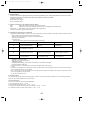
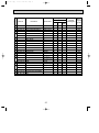
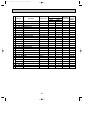
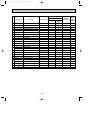
Correction:
“ 13. PARTS LIST ” has been modified on page 33 and 43.
Page
Revise point
Model
FUNCTIONAL PARTS
No.12 CAPILLARY
TUBE
33
FUNCTIONAL PARTS
No.17 TRANSFORMER
PU12EK
FUNCTIONAL PARTS
No.20 OUTDOOR
CONTROLLER BOARD
43
FUNCTIONAL PARTS
No.1 FAN MOTOR
Incorrect
Correct
T7W 588 425
T7W E07 425
T7W 850 799
T7W A30 799
T7W 850 315
T7W E08 315
T7W A05 763
T7W 853 763
PU42EK7
PU42EK71
PU42EK72
1
FEATURES
1. REDI-CHARGED REFRIGERANT SYSTEM
The industry’s first redi-charged refrigerant system.
There is no need to adjust the amount of refrigerant to match the piping length
on- site unless lines exceed 100ft.
You will see a major reduction in installation time and labor costs.
2. HIGH RELIABILITY AND EASY SERVICING
In addition to the self-diagnostic function, units are also equipped with a 3-minute time delay mechanism (cooling), an auto
restart function, an emergency operation function, a test run switch, etc., to assure high reliability and easy servicing.
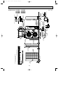
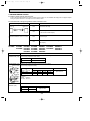
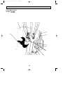
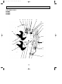
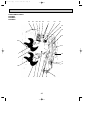
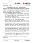
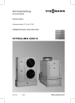
3. FOUR-WAY PIPING ACCESS MAKES
INSTALLATION LAYOUT EASY
Rear
Piping on the outdoor unit may be connected from either of
four directions: front, rear, side or beneath the base.
This easy-access design makes it possible to install a
number of units in a compact arrangement at a single site.
The outdoor unit allows for unheard-of flexibility in
determining a piping layout, thus greatly simplifying
installation.
Front
Base
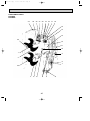
4. FRONT-ACCESS FACILITATES
MAINTENANCE
The outdoor unit has been designed with a front-access
service panel that allows easy access to all maintenance
point, regardless of the installation layout. What’s more, this
front panel may be removed by loosening only two screws.
It all adds up to greatly simplified maintenance work.
2
Right
OC247-E--1.qxp
2
04.8.11 4:25 PM
Page 3
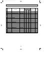
TECHNICAL CHANGE
(OC247 REVISED EDITION-A)
Change of the service parts.
Refer to “13. PARTS LIST” for the details.
PU18EK
PU24EK
PU30EK
PU36EK
PU42EK2
➔
➔
➔
➔
➔
PU18EK1
PU24EK1
PU30EK1
PU36EK1
PU42EK21
1. OUTDOOR CONTROLLER BOARD has been changed.
2. TRANSFORMER has been changed.
PU18EK ➔ PU18EK1
• CONTACTOR has been changed.
(OC247 REVISED EDITION-B)
PU24EK1 ➔ PU24EK2
PU30EK1 ➔ PU30EK2
PU36EK1 ➔ PU36EK2
• COMPRESSOR has been changed.
(PU24EK model) NH33NBD ➔ NH33NBDT
(PU30EK model) NH41NAD ➔ NH41NAHT
(PU36EK model) NH47NAD ➔ NH47NAHT
Refer to “5. SPECIFICATIONS”, “6. DATA” and “13. PARTS LIST” for details.
PU42EK7 ➔ PU42EK71
1. COMPRESSOR CONTACTOR has been changed to the one equipped THERMAL RELAY.
Refer to 8.WIRING DIAGRAM and 13.PARTS LIST for details.
2. OUTDOOR CONTROLLER BOARD has been changed.
Refer to “13. PARTS LIST” for details.
(OC247 REVISED EDITION-D)
PU24EK2 ➔ PU24EK3
PU30EK2 ➔ PU30EK3
PU36EK2 ➔ PU36EK3
PU42EK71 ➔ PU42EK72
• DRAIN PAN has been added.
<‘‘13. PARTS LIST’’ has been changed.>
PU36EK2 ➔ PU36EK3
• COMPRESSOR CAPACITOR for PU36EK, PU36EK1, PU36EK2 and PU36EK3 are unified.
3
OC247-E--1.qxp
3
04.8.11 4:25 PM
Page 4
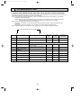
COMBINATION OF INDOOR AND OUTDOOR UNITS
Outdoor unit
PU
Indoor unit
12
Models
PL • AK
Service
manual No.
EK
18
EK
24
EK1
—
OC246
EK
30
EK1
EK2
EK3
—
EK
—
36
EK1
EK2
EK3
EK
42
EK1
EK2
EK3
—
EK7
EK2 EK21 EK71
EK72
—
—
OC001 SECOND EDITION
PL • FK(2) OC003 SECOND EDITION
PC • EK
PK • EK
OC194
OC001 SECOND EDITION
OC003 SECOND EDITION
OC192
OC001 SECOND EDITION
OC003 SECOND EDITION
—
—
PC • GK
4
OC278
—
—
—
PK • FK(3) OC121, OC196A
OC274
PK • FL(3) OC185A, OC275
—
—
—
—
—
—
—
—
—
—
—
—
—
—
—
—
—
—
—
—
—
—
—
—
—
—
—
—
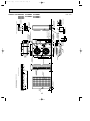
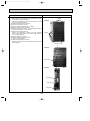
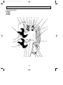
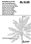
PART NAMES AND FUNCTIONS
Air outlet
Air outlet
Air intake
Air intake
PU18EK
PU18EK1
Outdoor unit
PU12EK
Outdoor unit
Air outlet
Air outlet
Air intake
Air intake
PU24EK PU30EK
PU24EK1 PU30EK1
PU24EK2 PU30EK2
PU24EK3 PU30EK3
Outdoor unit
PU36EK PU42EK2 PU42EK7
PU36EK1 PU42EK21 PU42EK71
PU36EK2
PU42EK72
PU36EK3
Outdoor unit
4
OC247-E--1.qxp
04.8.11 4:25 PM
5
Page 5
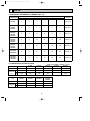
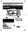
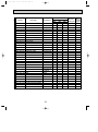
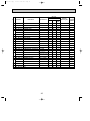
SPECIFICATIONS
MODELS : PU12EK PU18EK PU24EK PU30EK
PU18EK1 PU24EK1 PU30EK1
PU24EK2 PU30EK2
PU24EK3 PU30EK3
Model
Item
OUTDOOR UNIT MODELS
External finish
Power supply
V, phase, Hz
Max.fuse size (time delay)
A
Min.ampacity
A
Fan motor
F.L.A.
Model (type)
Compressor
R.L.A.
L.R.A.
Crankcase heater
A(W)
Refrigerant control
dB
Sound level
W
in.
Dimensions
D
in.
H
in.
Weight
lb
Control voltage (by built-in transformer)
Name
REFRIGERANT Charge
Oil<Model> OZ
REFRIGERANT PIPING
Liquid
in.
Pipe size
Gas
in.
Connection
Indoors
method
Outdoors
Between the indoor Height difference ft
& outdoor units Piping length ft
PU12EK
PU18EK
PU24EK
PU36EK PU42EK2 PU42EK7
PU36EK1 PU42EK21 PU42EK71
PU36EK2
PU42EK72
PU36EK3
PU30EK
PU36EK
PU42EK2
PU42EK7
PU18EK PU24EK PU24EK2 PU30EK PU30EK2 PU36EK PU36EK2 PU42EK2
PU12EK
PU42EK71
PU18EK1 PU24EK1 PU24EK3 PU30EK1 PU30EK3 PU36EK1 PU36EK3 PU42EK21
PU42EK72
Munsell 5Y 7/1
208/230, 1, 60
20
15
30
40
16
20
22
27
28
11
0.75+0.75
0.75
0.65
0.8+0.8
0.65+0.65
RH167NAB RH247NAB NH33NBD NH33NBDT NH41NAD NH41NAHT NH47NAD NH47NAHT NH569NXA ZR42K3PFV
12.0
11.5 10.8 14.0 12.9 17.5 15.1
20.0
20.4
8.9
37
52
57
73
75
87
81
105
109
29
0.16/0.17(33/39)
0.11/0.12(23/28)
Capillary tube
55
53
50
56
34-1/4
38-3/16
11-5/8
13-9/16
49-9/16
33-1/2
25-9/16
154
207
208 210 220 222
260
220
105
Indoor unit-outdoor unit:DC12V
R22
4 lbs 14 oz 5 lbs 8 oz 9 lbs 15 oz 10 lbs 2 oz 10 lbs 9 oz 12 lbs 9 oz 11 lbs 0 oz
37<MS32(N-1)>
49<MS32(N-1)> 42<SONTEX 200LT>
40<MS32(N-1)>
16<MS-56>
Not supplied(optional parts)
3/8
1/2
5/8
3/4
Flared
Flared
Max, 164
Max. 130
Max. 164
Max. 130
Operating range
Cooling
Maximum
Minimum
PU42EK7
Indoor intake air temperature
Outdoor intake air temperature
D.B. 95˚F, W.B. 71˚F
D.B. 67˚F, W.B. 57˚F
D.B. 115˚F
D.B. 0˚F w
w In case of the wind baffle installed.
(In case of the wind baffle is not installed, the minimum temperature is D.B. 23˚F)
5
OC247-E--1.qxp
6
04.8.11 4:25 PM
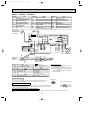
Page 6
DATA
1. ADDITIONAL REFRIGERANT CHARGE (R22 : oz)
Piping length (one way)
130 ft
145 ft
160 ft
164 ft
Factory
charged
—
—
—
4 lbs 14 oz
4
—
—
—
5 lbs 8 oz
2
4
6
8
9
9 lbs 15 oz
0
5
10
14
19
20
10 lbs 2 oz
0
5
10
14
19
20
10 lbs 9 oz
PU42EK2
PU42EK21
0
5
10
14
19
20
12 lbs 9 oz
PU42EK7
PU42EK71
PU42EK72
0
5
10
14
19
20
11 lbs 0 oz
Service Ref.
100 ft
115 ft
PU12EK
0
2
4
PU18EK
PU18EK1
0
2
PU24EK
PU24EK1
PU24EK2
PU24EK3
0
PU30EK
PU30EK1
PU30EK2
PU30EK3
PU36EK
PU36EK1
PU36EK2
PU36EK3
2. COMPRESSOR TECHNICAL DATA
at 68°F (Only PU42EK7 PU42EK71 : at 77°F)
PU30EK
PU24EK2
PU30EK2
PU30EK1
PU24EK3
PU30EK3
Unit
PU12EK
PU18EK
PU18EK1
PU24EK
PU24EK1
Compressor model
RH167NAB
RH247NAB
NH33NBD
NH33NBDT
NH41NAD
NH41NAHT
Winding R-C
Resistance
S-C
(")
2.47
1.59
0.92
0.92
0.63
0.62
4.62
3.22
1.93
1.93
1.37
1.51
at 68°F(Only PU42EK7 PU42EK71 : at 77°F)
PU42EK7
PU36EK2
PU42EK2
PU42EK71
PU36EK3
PU42EK21
PU42EK72
Unit
PU36EK
PU36EK1
Compressor model
NH47NAD
NH47NAHT
NH569NXA
ZR42K3PFV
Winding R-C
Resistance
S-C
(")
0.55
0.52
0.55
0.54
1.24
1.28
1.24
1.28
6
OC247-E--1.qxp
04.8.11 4:25 PM
Page 7
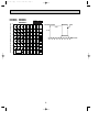
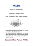
3. NOISE CRITERION CURVES
PU18EK
PU18EK1
OCTAVE BAND SOUND PRESSURE LEVEL, dB re 0.0002 MICRO BAR
LINE
90
80
70
NC-70
60
NC-60
50
NC-50
40
NC-40
30
NC-30
20
APPROXIMATE
THRESHOLD OF
HEARING FOR
CONTINUOUS
NOISE
NC-20
10
63
PU24EK
PU24EK1
PU24EK2
PU24EK3
OCTAVE BAND SOUND PRESSURE LEVEL, dB re 0.0002 MICRO BAR
SPL(dB)
50
125
250
500 1000 2000 4000
BAND CENTER FREQUENCIES, Hz
PU30EK
PU30EK1
PU30EK2
PU30EK3
SPL(dB)
55
LINE
NC-70
60
NC-60
50
NC-50
40
NC-40
30
NC-30
10
APPROXIMATE
THRESHOLD OF
HEARING FOR
CONTINUOUS
NOISE
63
125
NC-20
250
500
1000
2000
4000
80
70
NC-70
60
NC-60
50
NC-50
40
NC-40
30
NC-30
20
10
APPROXIMATE
THRESHOLD OF
HEARING FOR
CONTINUOUS
NOISE
63
125
NC-20
250
500
1000
PU36EK
PU36EK1
PU36EK2
PU36EK3
80
20
LINE
2000
4000
8000
BAND CENTER FREQUENCIES, Hz
90
70
SPL(dB)
53
90
8000
OCTAVE BAND SOUND PRESSURE LEVEL, dB re 0.0002 MICRO BAR
OCTAVE BAND SOUND PRESSURE LEVEL, dB re 0.0002 MICRO BAR
PU12EK
8000
SPL(dB)
55
90
80
70
NC-70
60
NC-60
50
NC-50
40
NC-40
30
NC-30
20
10
APPROXIMATE
THRESHOLD OF
HEARING FOR
CONTINUOUS
NOISE
63
125
NC-20
250
500
1000
2000
4000
BAND CENTER FREQUENCIES, Hz
BAND CENTER FREQUENCIES, Hz
7
LINE
8000
OC247-E--1.qxp
04.8.11 4:25 PM
Page 8
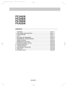
OCTAVE BAND SOUND PRESSURE LEVEL, dB re 0.0002 MICRO BAR
PU42EK2 PU42EK7
PU42EK21 PU42EK71
PU42EK72
SPL(dB)
56
LINE
90
MICROPHONE
3.3ft
80
UNIT
3.3ft
70
NC-70
60
NC-60
GROUND
50
NC-50
40
NC-40
30
NC-30
20
10
APPROXIMATE
THRESHOLD OF
HEARING FOR
CONTINUOUS
NOISE
63
125
NC-20
250
500
1000
2000
4000
8000
BAND CENTER FREQUENCIES, Hz
8
Handle for moving
3-3/4
For 10 units or less
Rear piping hole
1/2
5-7/16
8
9/32
Side air intake
Rear fresh
air intake
40
11-5/8
1
Outlet guide
installation hole
Handle for
moving
1-5/16
4
29/32
20-5/8
Drain hole
1-9/16
34-1/4
Drain hole
15/32 29/32 Oval holes
(standard bolt M10)
20-5/8
11-7/8
Air out
1/2
1/2
36
Front opening
15/32
R
4
1/
2-9/16
32
5/
2-3/8
4-3/4
Standard bolt length
Knock out holes
for power line 1-1/16
(for N.E.C)
Front right piping holes - detail Figures
R2
Knock out hole
for front piping
(refrigerant, drainage
and wiring)
(refrigerant, drainage
and wiring)
Bottom
piping hole
1-5/16
2-3/8
Refrigerant-pipe flared
connection
5/8
Refrigerant-pipe flared
connection
3/8
Knock out hole
for front piping
Service panel
Handle for moving
Ground terminal
Terminal bed for power line
Note:Allow adequate
upper clearance.
Service space
1/2
Outdoor Unit - necessary surrounding clearance
Terminal bed for indoor and outdoor unit connection
2-U-shaped
notched
holes
4-1/8
7-9/32
1-9/16 1-3/32
11-3/32
Air in
25-9/16
Air in
13-11/32
11/16
13
9/16
11-11/16
1-21/32
3-1/32
14-1/4
17-15/32
1-25/32
8
4
19-11/16
31/32 max.
7-9/32
21/32
32
36
Outdoor Unit-Necessary surrounding clearance
(Concentrated installation)
The upper side must be open.
5/
R2
9
3-5/32
1-3/4
7
04.8.11 4:25 PM
2-1/16
OC247-E--1.qxp
Page 9
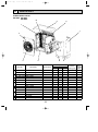
OUTLINES AND DIMENSIONS
Outdoor Unit PU12EK
Unit : inch
Handle for
moving
3-3/4
4
For 10 units or less
Rear piping hole
1/2
5-7/16
Rear fresh
air intake
Side air intake
8
40
1/4
11-5/8
Outlet guide
installation hole
20-5/18
1-9/16
Drain hole
Handle for moving
1
2
1
Air intake
17-3/18
34-1/4
Drain hole
1/2x7/8 Oval holes
(standard bolt W3/8(M10)
20-5/8
11-7/8
Air outlet
Air intake
14-1/4
1/2
15-7/8
1/2
36
Service panel
Ground
terminal
Handle for moving
2-3/8
1/2
R
4
1/
Bottom piping hole
16
3/
2-9/16
4-3/4
2-3/8
(for N.E.C)
Knock out holes for
power line 1-1/16
Standard bolt length
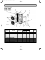
Outdoor Unit PU18EK
PU18EK1
Front right piping holesdetail figures
(refrigerant. drainage
R1
and wiring)
Knock out hole for
right piping
Knock out hole
for front piping
(refrigerant. drainage
and wiring)
Refrigerant pipe
(Flared) 3/8
Refrigerant pipe
(Flared) 5/8
Terminal block for power line
Note:Allow adequate
upper clearance.
Service space
1/2
Front opening
Terminal block for indoor and outdoor unit connection
2-U-shaped
notched
holes
1-5/16
4-1/8
7-9/32
4
19-11/16
1-5/8
7-1/18
9/16
13-7/8
36
11/16
1-9/161-1/16
13
13-7/4
1-3/4
21-3/4
33-1/2
7-9/32
11/16
16
1-3/4
Outdoor Unit-Necessary surrounding clearance
(Concentrated installation)
The upper side must be open.
3-1/8
8
Outdoor Unit - necessary surrounding clearance
3/
R1
10
2-1/16
04.8.11 4:25 PM
1 max.
OC247-E--1.qxp
Page 10
Unit : inch
5-7/16
Handle
for moving
3-3/4
1/2
Rear piping hole
For 10 units or less
12
40
Rear fresh
air intake
Side air intake
1
6
1/4
11-5/8
Air intake
Outlet guide
installation hole
1-9/16
Drain hole
Handle for moving
1
2
23-1/16
13-9/16
20-5/8
2-3/8
20-5/8
3-1/4
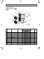
34-1/4
Drain hole
2-1/2x7/8 Oval holes
(standard bolt M10)W3/8(M10)
20-5/8
11-7/8
Air outlet
Air intake
11/16
Handle
for moving
Ground
terminal
2-3/8
1/2
2-U-shaped
notched
holes
1/2
4
1/
R
2-9/16
(for N.E.C)
Service space
4-3/4
2-3/8
36
Note:Allow adequate
upper clearance.
Front right piping holesdetail figures
Knock out hole
for right piping
R1
Bottom
3/
(refrigerant.
16
piping hole drainage and wiring)
Knock out hole
for front piping
(refrigerant. drainage
and wiring)
Refrigerant pipe (Flared)
PU24EK [5/8
PU30EK [3/4
Refrigerant pipe (Flared)
PU24EK [3/8
PU30EK [1/2
Terminal block for power line
3/8
Front opening
1/2
Outdoor Unit - necessary surrounding clearance
Terminal block for
indoor and outdoor
unit connection
Service panel
1-9/16
4-1/8
7-9/32
14-1/4
15-7/8
2-1/4
12
4
19-11/16
49-9/16
7-9/32
37-34
36
3-1/8
1-9/161-1/16
13
9/16
15-1/16
2-1/16
1-3/4
Outdoor Unit-Necessary surrounding clearance
(Concentrated installation)
The upper side must be open.
11/16
16
11
3/
Standard bolt length
Knock out holes for
power line 1-1/16
PU30EK
PU30EK1
PU30EK2
PU30EK3
R1
Outdoor Unit PU24EK
PU24EK1
PU24EK2
PU24EK3
2-1/16
04.8.11 4:25 PM
1 max.
OC247-E--1.qxp
Page 11
Unit : inch
Handle
for moving
3-3/4
6
For 10 units or less
Rear piping hole
1/2
5-7/16
12
Rear fresh
air intake
Side air intake
1/4
13-9/16
Outlet guide
installation hole
1-9/16
Drain hole
Handle for moving
1
20-5/8
2-3/8
20-5/8
7/8
38-3/16
Drain hole
2-1/2x7/8 Oval holes
(standard bolt W3/8(M10)
20-5/8
13-7/8
Air outlet
2-3/8
2-U-shaped
notched
holes
1/2
Bottom
piping hole
1-9/16
4-1/8
Handle
for moving
Ground
terminal
1/2
Front right piping holesdetail figures
Knock out hole
for right piping
R1
3/
(refrigerant.
drainage and wiring) 16
4-3/4
2-3/8
36
Outdoor Unit PU36EK PU42EK2 PU42EK7
PU36EK1 PU42EK21 PU42EK71
PU36EK2
PU42EK72
PU36EK3
Note:Allow adequate
upper clearance.
(for N.E.C)
Service space
1/2
Front opening
2-9/16
Refrigerant pipe Flared)
[1/2
Knock out hole
for front piping
(refrigerant. drainage
and wiring)
4
1/
R
1/2
Refrigerant pipe (Flared)
[3/4
Terminal block for power line
Terminal block for
indoor and outdoor
unit connection
Service panel
15-1/16
Air intake
15-7/8
Air intake
7-9/32
49-9/16
40
1-5/16
23-1/16
13-9/16
11/16
1-9/16 1-1/16
14-31/32
9/16
2-1/16
3-1/4
16-1/4
37-3/4
23-5/8
16
7-9/32
3/
The upper side must be open.
11/16
2-1/4
Outdoor Unit - necessary surrounding clearance
3-1/8
12
6
Outdoor Unit-Necessary surrounding clearance
(Concentrated installation)
Standard bolt length
Knock out holes for
power line 1-1/16
1 max.
12
R1
36
1-3/4
04.8.11 4:25 PM
2-1/16
OC247-E--1.qxp
Page 12
Unit : inch
OC247-E--1.qxp
04.8.11 4:25 PM
8
Page 13
WIRING DIAGRAM
MODEL : PU12EK
SYMBOL
PU18EK 1
NAME
SYMBOL
NAME
SYMBOL
NAME
C
COMPRESSOR CAPACITOR
LD1 ~ LD8
LED <CHECK, SERVICE>
TH3
OUTDOOR COIL THERMISTOR
C3
FAN CAPACITOR
MC
COMPRESSOR
X11 <O. B>
CRANKCASE HEATER RELAY
CH
CRANKCASE HEATER
MF
OUTDOOR FAN MOTOR (INNER THERMOSTAT)
X12 <O. B>
COMPRESSOR RELAY
CN3<O. B>
CONNECTING WIRES INDOOR/OUTDOOR
CONNECTOR
O. B
OUTDOOR CONTROLLER BOARD
ZNR <O. B>
VARISTOR
SW1, 2, 3<O. B> SELECT SWITCH <CHECK, SERVICE>
52C
CONTACTOR
CN4T<O. B>
TRANSFORMER CONNECTOR
T
TRANSFORMER
63H2
HIGH PRESSURE SWITCH <PROTECT>
FC <O. B>
FAN CONTROLLER
TB1
POWER SUPPLY TERMINAL BLOCK
F <O. B>
FUSE <6A>
TB3
CONNECTING WIRES INDOOR/OUTDOOR
TERMINAL BLOCK
51C
OVERCURRENT RELAY
FROM INDOOR UNIT
CONNECTING WIRES
12V DC (polar)
1
YLW
2
ORN
LED
TH3
TB3
O.B
SW1
4 3 2 1
LD1
LD2
LD3
LD4
LD5
LD6
LD7
LD8
SW2
CN2
X12 X11
FC
CN4
5
SW3
26C
OFF
ON
X12
2 1
S
A
RED
AC12.3V
RED
AC12.3V
WHT
BLU
RED
T/3
BLU
RED
S/2
BLU
YLM
R/1
YLM
ZNR
CH
WHT
52C
GRY
TRF
WHT
4
GRY
4 3 2 1
51CM
F
BLU
CN4T
BRN
MF1
CN3
YLM
1
63H2
YLM
2
63HI
X11
RED
63H2
CH
52C
MF
C3
ORN
208V
B
WHT
WHT
ORN
230V
T
RED
WHT
52C
TB1
POWER SUPPLY
208/230V
1phase 60Hz
L1
RED
L2
WHT
R
U
T
W
BLU
WHT
GR
2
51C
BLU
of LED (when both No. 1 and 2 of
Output display (light)
Compressor indoor command
—
—
Compressor ON
Outdoor fan ON
—
—
Crankcase heater ON
RED
R
C
MC
S
C
GRN
Main functions
LED NO.
LD1
LD2
LD3
LD4
LD5
LD6
LD7
LD8
1 WHT
SW3
€
are ¨OFF¨)
Check display (flush)
—
—
TH3 short / open
63H2 functions
—
—
TH3 overheat protection
Defective input
NOTES :If the operation stops to function of the protection device, the check display flashes.
How to use SW1 and 2
● Pressing SW1
€ erases the past check contents loaded on the microcomputer.
● The output display (light) remains during operation but pressing SW2
€
displays the past check contents in flashing mode. Pressing the
switch again returns to output display (light).
White connector
CAUTION FOR SERVICING
● The connector marked s— ⁄ı — is to turn the compressor ON-OFF during servicing.
The compressor stops by disconnecting the white connector as shown at the right.
CAUTION FOR POWER SUPPLY WIRING
● Since LD8 lights when normal power is turned "ON", check the power supply with
the "ON" or "OFF" LD8.
❈ Since the indoor transformer (T) is connected with 230V power, if 208V power is
used, change the wiring connection in the following Procedure.
When power Supply is 208V
RED
ORANGE
208V
WHITE
230V
CAUTION FOR INDOOR AND OUTDOOR CONNECTING WIRES
● Since the indoor and outdoor connecting wires has polarity, make sure to connect the same terminal numbers (1, 2) for indoor and outdoor units.
13
OC247-E--1.qxp
04.8.11 4:25 PM
Page 14
MODELS : PU18EK
SYMBOL
NAME
SYMBOL
NAME
SYMBOL
NAME
C
COMPRESSOR CAPACITOR
LD1 ~ LD8
LED <CHECK, SERVICE>
TH3
OUTDOOR COIL THERMISTOR
C3
FAN CAPACITOR
MC
COMPRESSOR
X11 <O. B>
CRANKCASE HEATER RELAY
CH
CRANKCASE HEATER
MF3
OUTDOOR FAN MOTOR (INNER THERMOSTAT)
X12 <O. B>
COMPRESSOR RELAY
CN3<O. B>
CONNECTING WIRES INDOOR/OUTDOOR
CONNECTOR
O. B
OUTDOOR CONTROLLER BOARD
ZNR <O. B>
VARISTOR
SW1, 2, 3<O. B> SELECT SWITCH <CHECK, SERVICE>
52C
CONTACTOR
CN6T<O. B>
TRANSFORMER CONNECTOR
T
TRANSFORMER
63H2
HIGH PRESSURE SWITCH <PROTECT>
FC <O. B>
FAN CONTROLLER
TB1
POWER SUPPLY TERMINAL BLOCK
F3 <O. B>
FUSE <6A>
TB3
CONNECTING WIRES INDOOR/OUTDOOR
TERMINAL BLOCK
51C
OVERCURRENT RELAY
1
YLW
2
ORN
LED
TH3
TB3
O.B
LD8
LD7
LD6
LD5
LD4
LD3
LD2
LD1
SW1
SW2
SW3
OFF
ON
2 1
26C
X12
X11
63H2
CN3
51CM
F3
T/3
BLU
MF3
S
A
BRN
11.5V AC
RED
15.5V AC
ORN
36.0V AC
RED
RED
63H2
CH
52C
208V
WHT
S/2
BLU
BLU
R/1
BLU
CH
WHT
GRY
WHT
52C
GRY
TRF
ZNR
RED
4
RED
CN6T
6 5 4 3 2 1
YLM
1
FC
5
YLM
YLM
2
CN2
X12 X11
YLM
FROM INDOOR UNIT
CONNECTING WIRES
12V DC (polar)
C3
MF3
ORN
B
WHT
ORN
WHT
T
230V
RED
WHT
52C
TB1
POWER SUPPLY
208/230V
1phase 60Hz
L1
RED
L2
WHT
R
U
T
W
WHT
GR
of LED (when both No. 1 and 2 of €SW3
Output display (light)
Compressor indoor command
—
—
Compressor ON
Outdoor fan ON
—
—
Crankcase heater ON
2
51C
BLU
1 WHT
RED
R
C
MC
S
C
GRN
Main functions
LED NO.
LD1
LD2
LD3
LD4
LD5
LD6
LD7
LD8
BLU
are ¨OFF¨)
Check display (flush)
—
—
Pipe temperature sensor short / open
63H2 functions
—
—
TH3 overheat protection
Defective input
NOTES :If the operation stops to function of the protection device, the check display flashes.
How to use SW1 and 2
● Pressing SW1
€ erases the past check contents loaded on the microcomputer.
● The output display (light) remains during operation but pressing SW2
€
displays the past check contents in flashing mode. Pressing the
switch again returns to output display (light).
White connector
CAUTION FOR SERVICING
s ⁄ı — is to turn the compressor ON-OFF during servicing.
● The connector marked —
The compressor stops by disconnecting the white connector as shown at the right.
CAUTION FOR POWER SUPPLY WIRING
● Since LD8 lights when normal power is turned "ON", check the power supply with
the "ON" or "OFF" LD8.
❈ Since the indoor transformer (T) is connected with 230V power, if 208V power is
used, change the wiring connection in the following Procedure.
When power Supply is 208V
RED
ORANGE
208V
WHITE
230V
CAUTION FOR INDOOR AND OUTDOOR CONNECTING WIRES
● Since the indoor and outdoor connecting wires has polarity, make sure to connect the same terminal numbers (1, 2) for indoor and outdoor units.
14
OC247-E--1.qxp
04.8.11 4:25 PM
Page 15
MODELS : PU24EK PU30EK PU36EK PU42EK2
SYMBOL
NAME
SYMBOL
NAME
SYMBOL
NAME
C
COMPRESSOR CAPACITOR
LD1~LD8
LED <CHECK, SERVICE>
TH3
OUTDOOR COIL THERMISTOR
C3, 4
FAN CAPACITOR
MC
COMPRESSOR (INNER THERMOSTAT)
X11 <O. B>
CRANKCASE HEATER RELAY
CH
CRANKCASE HEATER
MF3, 4
OUTDOOR FAN MOTOR (INNER THERMOSTAT)
X12 <O. B>
COMPRESSOR RELAY
CN3<O. B>
CONNECTING WIRES INDOOR/OUTDOOR
CONNECTOR
O. B
OUTDOOR CONTROLLER BOARD
ZNR <O. B>
VARISTOR
SW1, 2, 3<O. B> SELECT SWITCH <CHECK, SERVICE>
52C
CONTACTOR
CN6T<O. B>
TRANSFORMER CONNECTOR
T
TRANSFORMER
63H2
HIGH PRESSURE SWITCH <PROTECT>
FC <O. B>
FAN CONTROLLER
TB1
POWER SUPPLY TERMINAL BLOCK
R
RESISTOR
F3<O. B>
FUSE <6A>
TB3
CONNECTING WIRES INDOOR/OUTDOOR
TERMINAL BLOCK
C5
COMPRESSOR START CAPACITOR
19
COMPRESSOR START RELAY
1
YLW
2
ORN
LED
TH3
TB3
O.B
LD8
LD7
LD6
LD5
LD4
LD3
LD2
LD1
SW1
SW2
SW3
OFF
ON
2 1
FC
5
26C
X12
X11
63H2
CN3
S
A
BRN
11.5V AC
RED
15.5V AC
ORN
36.0V AC
RED
MF3
WHT
BLU
MF4
RED
63H2
CH
52C
208V
BLU
BLU
BLU
BLU
T/3
RED
S/2
RED
R/1
YLM
GRY
ZNR
CH
WHT
52C
GRY
TRF
WHT
4
WHT
51CM
F3
CN6T
6 5 4 3 2 1
YLM
YLM
2
1
CN2
X12 X11
YLM
FROM INDOOR UNIT
CONNECTING WIRES
12V DC (polar)
C3
MF3
ORN
B
WHT
BRN
ORN
WHT
T
C4
MF4
230V
YLW
RED
WHT
52C
TB1
POWER SUPPLY
208/230V
1phase 60Hz
L1
RED
L2
WHT
R
U
BLU
T
GR
W
BLU
SW3
€
MC
S
PU42EK2 only
BLU
52C
are ¨OFF¨)
Check display (flush)
—
—
TH3 short / open
63H2 functions
—
—
TH3 overheat protection
Defective input
R
U
T
W
BLU
of LED (when both No. 1 and 2 of
Output display (light)
Compressor indoor command
—
—
Compressor ON
Outdoor fan ON
—
—
Crankcase heater ON
RED
C
GRN
Main functions
LED NO.
LD1
LD2
LD3
LD4
LD5
LD6
LD7
LD8
R
C
WHT
WHT
WHT
R
1
19
BLU 3 19 2 RED
BLU R
C
MC
C
S
RED
C5
NOTES :If the operation stops to function of the protection device, the check display flashes.
How to use SW1 and 2
● Pressing SW1
€ erases the past check contents loaded on the microcomputer.
● The output display (light) remains during operation but pressing SW2
€
displays the past check contents in flashing mode. Pressing the
switch again returns to output display (light).
White connector
CAUTION FOR SERVICING
s ⁄ı — is to turn the compressor ON-OFF during servicing.
● The connector marked —
The compressor stops by disconnecting the white connector as shown at the right.
CAUTIONS FOR POWER SUPPLY WIRING
● Since LD8 lights when normal power is turned "ON", check the power supply with
the "ON" or "OFF" LD8.
❈ Since the indoor transformer (T) is connected with 230V power, if 208V power is
used, change the wiring connection in the following Procedure.
When power Supply is 208V
RED
ORANGE
208V
WHITE
230V
CAUTION FOR INDOOR AND OUTDOOR CONNECTING WIRES
● Since the indoor and outdoor connecting wires has polarity, make sure to connect the same terminal numbers (1, 2) for indoor and outdoor units.
15
OC247-E--1.qxp
04.8.11 4:25 PM
Page 16
MODELS : PU24EK1 PU30EK1 PU36EK1 PU42EK21 PU42EK7
PU24EK2 PU30EK2 PU36EK2
PU24EK3 PU30EK3 PU36EK3
SYMBOL
NAME
SYMBOL
NAME
SYMBOL
NAME
C
COMPRESSOR CAPACITOR
LD1~LD8
LED <CHECK, SERVICE>
TH3
OUTDOOR COIL THERMISTOR
C3, 4
FAN CAPACITOR
MC
COMPRESSOR (INNER THERMOSTAT)
X11 <O. B>
CRANKCASE HEATER RELAY
CH
CRANKCASE HEATER
MF1, 2
OUTDOOR FAN MOTOR (INNER THERMOSTAT)
X12 <O. B>
COMPRESSOR RELAY
CN3<O. B>
CONNECTING WIRES INDOOR/OUTDOOR
CONNECTOR
O. B
OUTDOOR CONTROLLER BOARD
ZNR <O. B>
VARISTOR
SW1, 2, 3<O. B> SELECT SWITCH <CHECK, SERVICE>
52C
CONTACTOR
CN4T<O. B>
TRANSFORMER CONNECTOR
T
TRANSFORMER
63H2
HIGH PRESSURE SWITCH <PROTECT>
FC <O. B>
FAN CONTROLLER
TB1
POWER SUPPLY TERMINAL BLOCK
R
RESISTOR
F <O. B>
FUSE <6A>
TB3
CONNECTING WIRES INDOOR/OUTDOOR
TERMINAL BLOCK
C5
COMPRESSOR START CAPACITOR
FROM INDOOR UNIT
CONNECTING WIRES
12V DC (polar)
1
YLW
2
ORN
19
COMPRESSOR START RELAY
26C
DISCHARGE THERMAL SWITCH
LED
TH3
TB3
O.B
SW1
4 3 2 1
LD1
LD2
LD3
LD4
LD5
LD6
LD7
LD8
SW2
X12 X11
CN2
FC
CN4
5
SW3
X12
RED
AC12.3V
BLU
WHT
BLU
BLU
RED
BLU
T/3
RED
S/2
YLW
R/1
YLW
YLW
ZNR
CH
WHT
WHT
GRY
GRY
52C
S
A
RED
MF1
51CM
F
4
TRF
AC12.3V
63H2
BLU
CN4T
4 3 2 1
BRN
MF2
CN3
YLW
2
1
26C
63HI
X12
WHT
OFF
ON
2 1
RED
63H2
CH
52C
MF1
B
BRN
WHT
WHT
ORN
MF2
230V
T
PU42EK7 Only
WHT
52C
TB1
POWER SUPPLY
208/230V
1phase 60Hz
RED
L2
WHT
GR
26C
R
U
T
W
BLU
R
C
WHT
BLU
RED
MC
S
C
GRN
PU42EK21 Only
BLU
52C
of LED (when both No. 1 and 2 of SW3
€ are ¨OFF¨)
Output display (light)
Check display (flush)
Compressor indoor command
—
—
—
—
TH3 short / open
Compressor ON
63H2 functions
Outdoor fan ON
—
—
26C functions (PU42EK7)
—
TH3 overheat protection
Crankcase heater ON
Defective input
R
U
T
WHT
WHT
R
W
1
19
19
2
RED
BLU 3
BLU
Main functions
LED NO.
LD1
LD2
LD3
LD4
LD5
LD6
LD7
LD8
C4
YLW
RED
L1
C3
ORN
208V
C5
NOTES :If the operation stops to function of the protection device, the check display flashes.
How to use SW1 and 2
● Pressing SW1
€ erases the past check contents loaded on the microcomputer.
● The output display (light) remains during operation but pressing SW2
€
displays the past check contents in flashing mode. Pressing the
switch again returns to output display (light).
White connector
CAUTION FOR SERVICING
s ⁄ı — is to turn the compressor ON-OFF during servicing.
● The connector marked —
The compressor stops by disconnecting the white connector as shown at the right.
CAUTIONS FOR POWER SUPPLY WIRING
● Since LD8 lights when normal power is turned "ON", check the power supply with
the "ON" or "OFF" LD8.
❈ Since the indoor transformer (T) is connected with 230V power, if 208V power is
used, change the wiring connection in the following Procedure.
When power Supply is 208V
RED
ORANGE
208V
WHITE
230V
CAUTION FOR INDOOR AND OUTDOOR CONNECTING WIRES
● Since the indoor and outdoor connecting wires has polarity, make sure to connect the same terminal numbers (1, 2) for indoor and outdoor units.
16
BLU R
C
MC
C
S
RED
OC247-E--1.qxp
04.8.11 4:25 PM
Page 17
MODEL : PU42EK71 PU42EK72
NAME
SYMBOL
NAME
SYMBOL
NAME
SYMBOL
THERMISTOR FOR PIPE TEMPERATURE
LD1~LD8
LED(CHECK,
SERVICE)
CN3<O.B> CONNECTOR
TH3
(CONNECTING WIRES INDOOR/OUTDOOR)
(32°F/15kΩ,77°F/5.4kΩ)
MC
CN4T<O.B> CONNECTOR(TRANSFORMER)
COMPRESSOR MOTOR (INNER THERMOSTAT) X11<O.B> AUXILIARY RELAY FOR CH
CH
CRANKCASE HEATER
MF1, 2
FAN MOTOR (INNER THERMOSTAT) X12<O.B> AUXILIARY RELAY FOR MC
C3, 4
RUN CAPACITOR FOR MF1,2
O.B
OUTD00R CONTROLLER BOARD
C
RUN CAPACITOR FOR MC
SW1·2·3<O.B> SELECT SWITCH(CHECK,SERVICE) 51C
ZNR<O.B> VARISTOR
THERMAL RELAY
MAGNETIC CONTACTOR FOR MC
FC<O.B> FAN CONTROLLER
T
TRANSFORMER
F<O.B>
TB1
TERMINAL BLOCK(POWER SUPPLY) 63H2
HIGH PRESSURE SWITCH(PROTECT)
TB3
TERMINAL BLOCK
(CONNECTING WIRES INDOOR/OUTDOOR) 26C
DISCHARGE THERMAL SWITCH
FUSE(6A/250V)
LED
YLW
ORN
TH3
TB3
O.B
SW1
LD1
LD2
LD3
LD4
LD5
LD6
LD7
LD8
4 3 2 1
FC
CN4
5
OFF
ON
X12
2 1
2
CN3
1
CN4T
BLU BLU
51C 26C
63H2
RED
ORN
BRN
230V
MF2
RED
TB1
L1
L2
RED
1/L1
51C
2/T1
BLU
WHT
3/L2
4/T2
WHT
6/T3
BLU C
52C
5/L3
GR
C4
YLW
WHT
POWER SUPPLY
208/230V
1 phase 60Hz
C3
MF1
96
A2
WHT
WHT
ORN
T
95
CH
52C
208V
WHT
GRY
GRY
WHT
WHT
RED AC12.3V
MF1
CH ZNR R/1 S/2 T/3
52C
S
A1
RED
63H2
51CM
F
TRF
BRN AC12.3V
MF2
4
WHT
WHT
4321
26C
63H1
X11
BLU
SW3
X12 X11
CN2
BLU
WHT
SW2
RED
RED
BLU
1
2
YLW
YLW
TO INDOOR UNIT
CONNECTING WIRES
DC 12V (polar)
52C
R
C
RED
GRN
MC
S
RED
Main functions of LED
LED NO.
LD1
LD2
LD3
LD4
LD5
LD6
LD7
LD8
(When both No.1 and 2 of SW3 are"OFF")
Output display(light)
Compressor indoor command
Compressor ON
Outdoor fan ON
Crankcase heater ON
Check display(flush)
Pipe temperature sensor short/open
63H2 functions
51C functions
26C functions
TH3 overheat protection
Defective input
How to use SW1 and 2
Pressing SW1 erases the past check contents
loaded on the microcomputer.
The output display (light) remains during operation
but pressing SW2 displays the past check contents
in flushing mode. Pressing the switch again returns
to output display(light).
NOTE: If the operation stops to function of the protection device, the check display flushes.
CAUTION FOR SERVICING
The connector marked
S
White connector
for 52C is to turn the compressor ON-OFF during servicing.
The compressor stops by disconnecting the white connector as shown at the right.
w When Power Supply is 208V
CAUTIONS FOR POWER SUPPLY WIRING
RED
w
Since LD8 lights when normal power is turned"ON", check the power supply with the"ON"or"OFF"LD8.
Since the indoor transformer(T) is connected with 230V power, if 208V power is used, change the
wiring connection as shown at the right.
208V
ORANGE 230V
CAUTION FOR INDOOR AND OUTDOOR CONNECTING WIRES
Since the indoor and outdoor connecting wires has polarity, make sure to connect the same terminal numbers(1,2)for indoor and outdoor units.
17
WHITE
OC247-E--1.qxp
9
04.8.11 4:25 PM
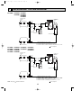
Page 18
REFRIGERANT SYSTEM DIAGRAM
PU12EK PU18EK PU24EK
PU18EK1 PU24EK1
PU24EK2
PU24EK3
Refrigerant pipe
(Option)
5/8
(with heat insulator)
Outdoor unit
Ball valve
Charge Check High
Pressure
plug
plug
Switch
Flexible tube
Flared connection
Outdoor coil
thermistor
TH3
Fusible
plug
Outdoor
heat
exchanger
Strainer
Accumulator
Compressor
Capillary tube
Flared connection
Refrigerant pipe
(Option)
3/8
(with heat insulator)
Ball valve
(with service port)
Capillary tube size (O.D.✕ I.D.✕ Length)
For PU12EK ({0.126✕{0.071✕ 31.5)
For PU18EK, PU18EK1({0.126✕{0.063✕ 31.5) ✕ 2 sets
For PU24EK, PU24EK1, PU24EK2, PU24EK3({0.126✕{0.063✕ 17.3) ✕ 2 sets
Flow of refrigerant
PU30EK
PU30EK1
PU30EK2
PU30EK3
PU36EK PU42EK2 PU42EK7
PU36EK1 PU42EK21 PU42EK71
PU36EK2
PU42EK72
PU36EK3
Refrigerant pipe
(Option)
3/4
(with heat insulator)
Outdoor unit
Ball valve
Charge Check High
Pressure
plug
plug
Switch
Flexible tube
Flared connection
Outdoor coil
thermistor
TH3
Fusible
plug
Outdoor
heat
exchanger
Strainer
Accumulator
Compressor
Capillary tube
Flared connection
Refrigerant pipe
(Option)
1/2
(with heat insulator)
NOTE :The symbol
indicates the diameter.
Ball valve
(with service port)
Capillary tube size (O.D.✕ I.D.✕ Length)
For PU30EK, PU30EK1, PU30EK2, PU30EK3 ({0.157✕{0.079✕ 29.1) ✕ 2 sets
For PU36EK, PU36EK1, PU36EK2, PU36EK3 ({0.157✕{0.079✕ 17.7) ✕ 2 sets
For PU42EK2, PU42EK21({0.157✕{0.079✕ 7.1) ✕ 2 sets
For PU42EK7, PU42EK71, PU42EK72({0.157✕{0.079✕ 21.7) ✕ 2 sets
Flow of refrigerant
18
OC247-E--1.qxp
10
04.8.11 4:25 PM
Page 19
MICROPROCESSOR CONTROL
OUTDOOR MICROPROCESSOR CONTROL
1. Protection function
(1) As soon as a reversed phase, an open phase, or a P. C. board trouble is sensed, the operation stops and the check
code is displayed by LED on the outdoor controller board.
(2) When a protection function such as high pressure switch and overcurrent relay works for the first time, the operation
stops and restarts after 3-minute time delay mode. When the second protection function works, the operation stops
and the check code is displayed by LED. This condition continues until the outdoor unit receives OFF command from
the indoor controller board. Check code indication continues until the outdoor unit receives the ON command from
the indoor controller board.
(3) The second protection function is not necessary to be the same as the first one. The content of the second protection
function is loaded in the memory, which is cleared when SW1 turns to ON or the next check mode starts.
2. Control by outdoor coil thermistor
(1) Unit control
Outdoor coil temperature range for control is from -40˚F to 194˚F. When reading 194˚F or above, the outdoor coil
thermistor is regarded as short-circuit. When reading -40˚F or below, the outdoor coil thermistor is regarded as
open-circuit. An open circuit is not sensed for the first 7 min. after the compressor start up, but is sensed during
defrosting operation or for the first 10 seconds after the compressor start-up.
(2) Target temperature of outdoor coil temperature
Fan rotational frequency is controlled so that the outdoor coil temperature keeps 95˚F ± 4˚F.
3. Unit operation control
The compressor receives signal from the indoor unit and make the outdoor unit start or stop.
4. Fan control
Fan rotational frequency is phase-controlled so that the outdoor coil temperature reaches the target temperature.
This control enables cooling operation even if the outdoor temperature is low. Fan rotational frequency is adjusted by fan
output. Fan output is divided into 256 steps from 0 to 255 and is controlled every 30 seconds.
(1) Initial setting
A. When power is turned to on, or when the compressor restarts after interval of 30 minutes or more :
● If the outdoor coil thermistor reads 46˚F or below, the fan output step becomes 100.
● If the outdoor coil thermistor reads above 46˚F, the fan output step becomes 200.
B. When the compressor restarts within 30 minutes after stop, the fan output step is the same as the fan output before
the compressor stops.
C. When the operation mode is changed within 30 minutes after the compressor stop, the fan output step becomes 100.
D. When the operation mode is changed after the compressor interval of more than 30 minutes, the fan output step is
the same as described in A.
(2) For the first 2 minutes after the compressor start-up, the fan operates at the initial setting output, and then every other
30 seconds, the fan output is adjusted depending on the difference between the outdoor coil temperature and the
target temperature. But as soon as the outdoor coil temperature becomes 122˚F or above, the fan output step becomes 255.
(3) When the outdoor coil thermistor reads 122˚F or above, the fan output step becomes 255.
(4) When the high pressure switch (63H1) functions, the fan output step becomes 255. After that, when the switch returns,
the fan control returns to the normal control.
5. Crankcase heater control
(1) With jumper wire J3
The crankcase heater is ON from the power is turned to on till the compressor starts, and turns to ON 1 hour after the
compressor stop.
(2) Without jumper wire J3
The crankcase heater is ON from the power is turned to on till the compressor starts, and repeats ON/OFF on a 1-hour
schedule.
19
OC247-E--1.qxp
04.8.11 4:25 PM
Page 20
6. Fixed fan-output
While the compressor is operating and the fan output step is indicated by LED, pushing SW2 fixes the fan output of that time.
The fixed fan-output can be released when either of the following conditions is satisfied.
1 SW2 is pushed again.
2 SW3 setting is changed.
3 The compressor stops.
7. Function of switches on the outdoor controller board
SW1
: Clears the check code memory (push-button switch)
SW2
: Switches the output state indication and the check code display (push-button switch)
SW3-1and3- 2 : Switches the output state indication items (dip-switch)
For further information, please refer to page 21.
8. Operation during the power-on-reset state
(1) When the circuit breaker is turned to ON, the microprocessor enters the power-on-reset state, which continues until the
direct current for the microprocessor control reaches 12V.
Then the microprocessor starts operation in the following order.
1 Each I/O port clearance
2 Function input
Function depends on jumper wires set beforehand in the factory.
Jumper wire
Function
J1
Reversed phase sensor
J2
Not applied for series PU
J3
J4
With jumper wire
Without jumper wire
Sensed
Not sensed
Crankcase heater control
Refer to 5 (1) on page 19.
Refer to 5 (2) on page 19.
Target temperature of outdoor
coil temperature
86˚F
For heat pump units
95˚F
For cooling unit
3 Check for a reversed phase
4 Check for an open phase (with J1)
5 50/60Hz judgment
6 EEPROM data loading (check mode, and total time of compressor operation)
7 Coil temperature initial input
(2) If an open phase or a reversed phase is sensed, LED blinks every other second.
NOTE
❈ If power is not supplied to the transformer and the microprocessor, the microprocessor does not work and can sense neither a reversed phase nor an open phase.
❈ If a contact point of protective device such as the high pressure switch has already been opened in the power-on-reset
state, it is regarded as an open phase.
In this case, all LED are OFF.
9. 100% fan output
Fan output is fixed to 255 (100%) by shorting CN22. However, the fan stops during compressor OFF or defrosting operation.
Open circuit of CN22 enables the fan control to start.
10. Time shortening
Short circuit of CN21 shortens the time listed below.
1) Fan control period : 30 sec. ➝ 3 sec.
2) Three-minute time delay function : 3 min. ➝ 3 sec.
3) Compressor ON/OFF time for bypass valve ON/OFF : 30 min. ➝ 30 sec.
4) Compressor ON time to start other functions : x min. ➝ x sec.
20
OC247-E--1.qxp
04.8.11 4:25 PM
11
Page 21
TROUBLESHOOTING
1. SERVICE DATA INDICATION BY SWITCHES ON OUTDOOR CONTROLLER BOARD
Setting dip switches SW2 and SW3 on the outdoor controller board enables LED to show the output state and check code.
Output state is shown by LED lighting, and check code by blinking.
SW1 : Turning SW1 ON clears the check code. If SW1 is turned ON while the check code is blinking , the indication
changes to output state indication.
NOTE : SW1 is usually available independent of SW3 setting. As an exception, when the check code shows a
reversed phase or an open phase during the power-on-reset state, SW1 is not available.
SW2 : SW2 is turned ON by pressing, and OFF by releasing.
When SW3-1 and SW3-2 are OFF, pressing SW2 changes indication between output state and check code
alternately.
When SW2 is turned On with SW3-1 OFF and SW3-2 ON, the compulsory defrosting starts.
SW3 : Output state indication items depend on the combination of SW3-1 ON/OFF and SW3-2 ON/OFF.
Changed alternately by pressing SW2.
Check code
Output state
Outdoor coil
temperature
(bit)
Fan output
step
(bit)
Total time of
compressor
operation(Hr)
SW3-1
OFF
OFF
OFF
ON
ON
SW3-2
OFF
OFF
ON
OFF
ON
1
1
256
2
2
512
Lighting
LED
Blinking
LD1
Reversed phase
LD2
Open phase
LD3
Outdoor coil thermistor
is abnomal.
During 63H1 function
4
4
1024
LD4
63H2 function
Compressor ON
8
8
2048
LD5
51C function
Outdoor fan ON
16
16
4096
LD6
26C function
4-way valve ON (HEAT PUMP Only)
32
32
8192
LD7
Overheat protection
Bypass valve ON (HEAT PUMP Only)
64
64
16384
LD8
Input circuit on controller
board is abnormal
Crankcase heater ON
128
128
32768
Compressor ON command from
indoor controller
Heating operation command from
indoor controller
21
OC247-E--1.qxp
04.8.11 4:25 PM
Page 22
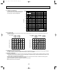
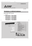
1-1 Outdoor coil temperature
To obtain data on the outdoor coil temperature,
add the number of bits of lighting LEDs, and
see the graph to find the temperature.
˚F
212
(Short 38 bits)
176
140
Temperature
104
68
32
-4
-40
(Open 219 bits)
0
50
100
150
200
255
Number of bits
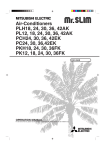
1-2 Fan output step
To obtain data on the fan output step, add the number of bits of lighting LEDs, and see the graph below to find the fan
rotational frequency.
2 PU18EK PU36EK PU42EK2 PU42EK7
PU18EK1 PU36EK1 PU42EK21 PU42EK71
PU36EK2
PU42EK72
PU36EK3
PU30EK
PU30EK1
PU30EK2
PU30EK3
Fan rotational frequency (rpm)
Fan rotational frequency (rpm)
1 PU12EK PU24EK
PU24EK1
PU24EK2
PU24EK3
800
600
400
200
0
50
100
150
200
250
Fan output step (bit)
800
600
400
200
0
50
100
150
200
250
Fan output step (bit)
1-3 Total time of compressor operation
Compressor operation time is indicated in 256 hour units. To obtain the compressor operation time, add the hours of lighting LEDs. During the compressor operation time indication, SW2 is not available.
1-4 Check code indication
● When a protection function works for the first time during operation, the operation stops and restarts after the 3-minutes
time delay mode. When the protection function works again, the operation stops. (Check mode) When both SW3-1 and
SW3-2 are OFF, the check code is indicated.
● If the outdoor controller board receives the compressor ON command from the indoor controller board during check
mode the indication changes to output state indication.
● By pressing SW2 during normal operation. operation will continue.
● The latest check code is indicated.
22
OC247-E--1.qxp
04.8.11 4:25 PM
Page 23
2. TROUBLESHOOTING ACCORDING TO CHECK CODE
Blinking
Diagnosis of malfunction
LED
LD1 Reversed phase
Cause
Check point
This model does not have this
function.
No need to be checked.
This model does not have this
function.
No need to be checked.
LD2
Open phase
LD3
Outdoor coil thermistor is
● Outdoor coil thermistor is
abnormal. (Open circuit or short
broken.
circuit)
● Thermistor was connected
incorrectly.
LD4
High pressure switch (63H2)
function
● 63H2 was badly connected.
● 63H2 was working.
● Check 63H2 and the outdoor fan motor.
● Check if refrigerant supply is low.
● Check if air cycle is short-cycled.
LD5
Thermal relay function
(PU42EK7)
● 51C is working.
● Check 51C.
LD6
Thermal switch (26C) function
(PU42EK7)
(PU42EK71)
● 26C was connected incorrectly. ● Check 26C.
● 26C is working.
● Check if refrigerant supply is low.
● Check if the capillary tube is clogged.
LD7
Over heat protection
● The thermistor is broken.
● Coil temperature is over
153˚F.
● Measure the resistance of the thermistor.
● Check the outdoor fan motor.
● Check if air cycle is short-cycled.
LD8
Input circuit of outdoor controller board is abnormal.
● Pulse input is abnormal.
● Replace the outdoor controller board.
● Measure the resistance of the thermistor.
● Check the thermistor. If normal, replace the outdoor controller board.
3. WHEN OUTDOOR UNIT DOES NOT WORK
Cause
1) Indoor/outdoor connecting wires are poorly connected.
(Refer to next page.)
2) Power supply is poorly connected.
3) Connector or transformer is broken.
4) Fuse (6A) in the outdoor controller board is blown.
Check points
1) Check the connecting wires.
2) Check the power supply.
3) Check connector and transformers.
4) Check the fuse.
23
OC247-E--1.qxp
04.8.11 4:25 PM
Page 24
4. WRONG WIRING ON SITE
4-1 Between remote controller and indoor unit
If wire is disconnected between the remote controller and the indoor unit, the POWER ON display does not appear despite
turning the power switch ON. The beep sound is not heard, either.
4-2 Phenomena due to wrong wiring between indoor and outdoor units
Wrong wiring
Indoor unit
1
Thermostat
Outdoor unit
1
2
Phenomena
OFF
The outdoor unit stops.
ON
Operation stops. 9 minutes later, the check code ¨P8¨ appears
on the remote controller display.
OFF
Operation stops.
ON
9 minutes later, the check code ¨P8¨ appears on the remote controller display.
2
Disconnect between 1 and 1 or 2 and
2.
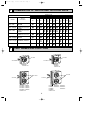
5. HOW TO CHECK THE PARTS
PU12EK PU18EK PU24EK PU30EK
PU18EK1 PU24EK1 PU30EK1
PU24EK2 PU30EK2
PU24EK3 PU30EK3
PU36EK PU42EK2 PU42EK7
PU36EK1 PU42EK21 PU42EK71
PU36EK2
PU42EK72
PU36EK3
Parts name
OUTDOOR COIL
THERMISTOR (TH3)
FAN MOTOR(MF,1,2,3,4)
[PU12,18,24,30]
Protector
Check points
Disconnect the connector then measure the resistance using a tester.
(Surrounding temperature 50°F~86°F)
Normal
Abnormal
4.3k"~9.6k"
Open or short
Measure the resistance between the terminals using a tester.
(Surrounding temperature 68°F)
White
Orange(Yellow)
Red(Brown)
Blue
[PU36,42]
White
Orange(Yellow)
Red(Brown)
Motor terminal
or
Relay connector
Abnormal
Normal
PU36
PU42
77.3"
100.2"
73.9"
61.5"
Blue — Red (Brown) 134.6"
83.8"
118.7"
79.8"
PU12,18 PU24,30
White — Blue
Protector
OPEN : 275±9˚F
CLOSE : 187±27˚F
Blue
Protector
CRANKCASE
HEATER (HC)
Measure the resistance between the terminals using a tester.
Abnormal
Normal
PU12,18
PU24,30,36,42
1920"
1340"
Open or short
24
Open or short
OC247-E--1.qxp
12
04.8.11 4:25 PM
Page 25
DISASSEMBLY INSTRUCTIONS
NOTE : All panels are clasped, and should be
removed by shifting up and down.
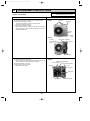
Outdoor unit (PU18EK)
OPERATING PROCEDURE
PHOTOS
1. Electrical parts
(1) Remove top panel (3 screws in front, 2 screws in rear)
(2) Remove cover panel (1 screw).
The panel is anchored by clicks to the side panel.
Remove by pulling towards you.
(3) Remove cover panel (1 screw).
The panel is anchored by clicks on the right and left sides.
After removing the screw, pull the panel down and remove it
by pulling towards you.
Photo 1
Screws
Top panel
Service
panel
Front panel
Photo 2
Outdoor
controller
board
Transformer Capacitor
Contactor
Screws
2. Fan motor
(1) Remove front panel (3 screws).
Open the panel to a 45 degree angle and lift to remove. The
panel is clasped at three points on the left side.
(2) Remove propeller (1 set nut).
(3) Remove fan motor (3 screws).
Remove lead connector.
Cover
panel
Terminal block
Photo 3
Separator support plate
Motor support
Propeller
High-pressure switch
Lead
connectors
Valve bed
Propeller nut
25
Crankcase heater
OC247-E--1.qxp
04.8.11 4:25 PM
Page 26
OPERATING PROCEDURE
PHOTOS
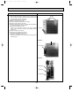
3. Heat Exchanger, Compressor
(1) Remove the rear panel (2 screws in front, 1 screw on the
side, 3 screws in the rear). Remove the valve bed, and open
the rear panel to the rear to remove.
(2) Remove right side panel (4 screws).
(3) Remove rear guard (3 screws).
(4) Remove separator support plate (4 screws).
(5) Remove motor support (2 screws).
(6) Remove valve bed (5 screws). The valve bed is clasped on
the right and left sides. Lift to remove.
(7) Remove the electrical parts box.
Remove the respective connector from high pressure
switch, crank case heater, outdoor coil thermistor and fan
motor lead.
(8) Remove separator (2 screws).
(9) Remove heat exchanger (2 screws).
Disconnect the welded section of pipe.
(10) Remove compressor (3 set nuts).
Remove the weldment of the compressor suction pipe and
discharge pipe.
Photo 4
Screws
Photo 5
Accumulator
Photo 6
Charge plug
Ball valve
Compressor
26
Screws
Heat exchanger
OC247-E--1.qxp
04.8.11 4:25 PM
Page 27
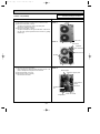
NOTE : All panels are clasped, and should be
removed by shifting up and down.
Outdoor unit (PU24EK)
OPERATING PROCEDURE
PHOTOS
1. Electrical parts
(1) Remove top panel (3 screws in front, 2 screws in rear)
(2) Remove cover panel (1 screw).
The panel is anchored by clicks to the side panel.
Remove by pulling towards you.
(3) Remove cover panel (1 screw).
The panel is clasped on the right and left sides. After removing the screw, pull the panel down and remove it by pulling
towards you.
Screws
Photo 1
Panel cover
Photo 2
Fan motor
capacitor
52C contactor
Terminal block
Screws
2. Fan motor
(1) Remove front panel (3 screws).
Open the panel to a 45 degree angle and lift to remove. The
panel is clasped at three points on the left side.
(2) Remove propeller (1 set nut).
(3) Remove fan motor (3 screws).
Remove lead connector.
Photo 3
Motor support
Separator support place
Propeller
nut
High-pressure
switch
Valve bed
Crank case heater
Propeller fan
27
OC247-E--1.qxp
04.8.11 4:25 PM
Page 28
OPERATING PROCEDURE
PHOTOS
3. Heat Exchanger, Compressor
(1) Remove the rear / right side panel (2 screws in front, 1 screw
on the side, 3 screws in the rear).
Remove the electrical box, valve bed, and open to the rear
to remove (anchors attached).
(2) Remove right side panel (4 screws).
(3) Remove rear guard (3 screws).
(4) Remove separator support plate (4 screws).
(5) Remove motor support (2 screws).
(6) Remove valve bed (5 screws). The valve bed is clasped on
the right and left sides. Lift to remove.
(7) Remove the electrical parts box.
Remove the respective connector from high pressure
switch, Low-pressure switch, crank case heater, shell thermo, and fan motor lead.
(8) Remove separator (2 screws).
(9) Remove heat exchanger (2 screws).
Remove piping weld zone.
(10) Remove compressor (3 set nuts).
Remove the weldment of the compressor suction pipe and
discharge pipe.
Screws
Photo 4
Screws
Heat exchanger
Photo 5
Accumulator
Photo 6
Charge plug
Ball valve
Compressor
28
OC247-E--1.qxp
04.8.11 4:25 PM
13
Page 29
PARTS LIST
STRUCTURAL PARTS
PU12EK PU18EK
PU18EK1
10
9
8
1
7
2
3
4
5
6
Q'ty / set
No.
Parts No.
Parts Name
PU
Specifications
12EK
18EK
18EK1
1
1
1
1
R01
A08
662 SIDE PANEL
R01
A00
662 SIDE PANEL
R01
A08
668 FRONT PANEL
R01
A00
668 FRONT PANEL
1
3 R01
A00
675 FAN GUARD
1
1
1
686 BASE ASSEMBLY
1
1
1
1
1
1
1
1
1
1
1
1
2
4 R01
A00
1
R01
A08
661 SERVICE PANEL
R01
A00
661 SERVICE PANEL
1
6 R01
A00
658 PANEL COVER
1
R01
A08
682 REAR PANEL
R01
A00
682 REAL PANEL
R01
A08
698 REAR GUARD
R01
A00
698 REAR GUARD
1
9 R01
A00
641 TOP PANEL
1
1
1
1
1
1
5
7
8
1
10 T7W E03 130 MOTOR SUPPORT
29
Wiring
Remarks
Diagram
(Drawing No.)
Symbol
OC247-E--1.qxp
04.8.11 4:25 PM
Page 30
STRUCTURAL PARTS
PU24EK PU30EK
PU24EK1 PU30EK1
PU24EK2 PU30EK2
PU24EK3 PU30EK3
12
11
10
9
1
2
3
3
4
5
7
6
8
Q'ty / set
Parts Name
Specifications
PU24EK PU30EK
PU24EK1 PU30EK1
PU24EK2 PU30EK2
PU24EK3
PU30EK3
No.
Parts No.
1
R01 A11 662
SIDE PANEL (LEFT)
1
1
2
R01 A00 675
FAN GUARD
2
2
3
R01 A00 655
PANEL HANDLE
3
3
4
R01 A11 668
FRONT PANEL
1
1
5
R01 A10 686
BASE ASSEMBLY
1
1
6
T7W E00 529
DRAIN PAN
7
R01 A11 661
SERVICE PANEL
1
1
8
R01 A00 658
PANEL COVER
1
1
9
R01 A11 682
REAR PANEL
1
1
10 T7W E04 698
REAR GUARD
1
1
11 T7W E02 641
TOP PANEL
1
1
12 T7W E04 130
MOTOR SUPPORT
1
1
1
30
Wiring
Remarks
Diagram
(Drawing No.)
Symbol
OC247-E--2.qxp
04.8.11 4:26 PM
Page 31
STRUCTURAL PARTS
PU36EK PU42EK2 PU42EK7
PU36EK1 PU42EK21 PU42EK71
PU36EK2
PU42EK72
PU36EK3
12
1
11
10
9
8
2
3
4
4
5
6
7
Q'ty / set
No.
Parts No.
Parts Name
Specifications
1 R01 A14 662 SIDE PANEL (LEFT)
Wiring
Remarks
Diagram
(Drawing No.)
36EK
42EK2 42EK7
Symbol
36EK1 36EK3
42EK72
42EK21 42EK71
36EK2
1
1
1
1
1
PU
2 R01 A14 668 FRONT PANEL
1
1
1
1
1
3 R01 A00 675 FAN GUARD
2
2
2
2
2
4 R01 A00 655 PANEL HANDLE
3
3
3
3
3
1
1
1
1
1
5
R01 A14 686 BASE ASSEMBLY
R01 AK6 686 BASE ASSEMBLY
1
6 T7W E17 529 DRAIN PAN
1
7 R01 A14 658 PANEL COVER
1
1
1
1
1
8 R01 A14 682 REAR PANEL
1
1
1
1
1
9 R01 A14 661 SERVICE PANEL
1
1
1
1
1
10 T7W E03 698 REAR GUARD
1
1
1
1
1
11 R01 A14 641 TOP PANEL
1
1
1
1
1
1
1
1
1
1
12
R01 85H 130 MOTOR SUPPORT
T7W E02 130 MOTOR SUPPORT
31
OC247-E--2.qxp
04.8.11 4:26 PM
Page 32
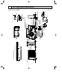
FUNCTIONAL PARTS
PU12EK PU18EK
PU18EK1
22
18 17
21 20 19
16 15 14
13
23
12
11
10
9
1 2 3 4 5
32
6
7
8
OC247-E--2.qxp
04.8.11 4:26 PM
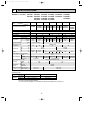
Page 33
Q'ty / set
No.
Parts No.
Parts Name
PU
Specifications
12EK
18EK
18EK1
1
1
1
1
1
1
OPEN psiG 469
1
1
1
T7W 966 238 OVERCURRENT RELAY
MRA-98880-9030
1
T7W 969 238 OVERCURRENT RELAY
MRA98881-093
T97 665 600 COMPRESSOR
RH247NAB
T92 650 452 COMPRESSOR
RH167NAB
1
6 T7W 850 236 CRANKCASE HEATER
240V 30W
7 R01 943 410 BALL VALVE
3/8
R01 951 411 BALL VALVE
5/8
R01 943 411 BALL VALVE
5/8
1 T7W 850 763 FAN MOTOR
S6V-85FPH
2 R01 A00 115 PROPELLER
3 T7W 850 208
4
5
8
HIGH PRESSURE SWITCH
Wiring
Remarks
Diagram
(Drawing No.)
Symbol
MF3,MF
63H2
51C
1
1
51C
1
1
MC
1
1
1
1
1
1
1
1
MC
CH
1
9 R01 590 413 CHARGE PLUG
2
2
2
10 R01 A00 440 ACCUMULATOR
1
1
1
11 T7W 973 507 FUSIBLE PLUG
1
1
1
2
2
1
1
TH3
1
52C
12
T7W E07 425 CAPILLARY TUBE
0.126o0.071o31.5
R01 600 425 CAPILLARY TUBE
0.126o0.063o31.5
13 R01 J07 202 OUTDOOR COIL THERMISTOR
14
15
1
T7W A30 708 CONTACTOR
S-U12UL 215VAC
T7W 651 215 CONTACTOR
VC-20F 230VAC
17
1
1
1
T7W 969 723 COMPRESSOR CAPACITOR 30µF 380V
T7W 966 723 COMPRESSOR CAPACITOR 25µF 370V
16
1
52C
1
1
C
1
R01 576 255 FAN MOTOR CAPACITOR
3µF 440V
R01 A00 255 FAN MOTOR CAPACITOR
2.5µF 440V
1
T7W A30 799 TRANSFORMER
RED :12.3VAC,0.06A
BRN :12.3VAC,0.06A
1
T7W 850 799 TRANSFORMER
RED :15.5VAC,0.2A
BRN :11.5VAC,0.2A
ORN :36.0VAC,0.02A
C
1
C3
C3
1
1
T
T
18 T7W 410 239 FUSE
250V 6A
1
1
1
F3<O.B>,F<O.B>
19 T7W 850 716 TERMINAL BLOCK
3P(L1,L2,GR)
1
1
1
TB1
1
O.B
20
1
T7W E08 315 OUTDOOR CONTROLLER BOARD
1
T7W 850 315 OUTDOOR CONTROLLER BOARD
21 R01 556 246 TERMINAL BLOCK
22
2P(1,2)
1
R01 K91 408 OUTDOOR HEAT EXCHANGER
O.B
1
1
1
1
1
1
1
T7W 850 408 OUTDOOR HEAT EXCHANGER
23 R01 30L 097 NUT
1
33
TB3
OC247-E--2.qxp
04.8.11 4:26 PM
Page 34
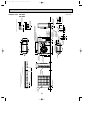
FUNCTIONAL PARTS
PU24EK
PU24EK1
PU24EK2
PU24EK3
21
20
17 16
18
19
15
14
13
12
11
22
10
1
9
2
23
1
2
3
4
34
5
6
7
8
OC247-E--2.qxp
04.8.11 4:26 PM
Page 35
Q'ty / set
No.
Parts No.
Parts Name
1
T7W 851 763 FAN MOTOR
2
R01 A00 115 PROPELLER
3
T7W 850 208 HIGH PRESSURE SWITCH
4
5
S6V-60FPN
OPEN psiG 363
R01 41L 413 CHARGE PLUG
T97 517 300 COMPRESSOR
PU
Specifications
NH33NBD
24EK
24EK1
24EK2
24EK3
2
2
2
2
2
2
1
1
1
2
2
2
1
1
Remarks
(Drawing No.)
Wiring
Diagram
Symbol
MF3,4,1,2
63H2
MC
1
MC
CH
T97 501 400 COMPRESSOR
NH33NBDT
6
T7W 851 236 CRANKCASE HEATER
240V 43W
1
1
1
7
R01 943 410 BALL VALVE
3/8
1
1
1
8
R01 951 411 BALL VALVE
5/8
1
1
1
9
T7W E17 425 CAPILLARY TUBE
0.126o0.063o17.3
2
2
2
10 T7W 973 507 FUSIBLE PLUG
1
1
1
11 R01 A12 440 ACCUMULATOR
1
1
1
12 R01 J01 202 OUTDOOR COIL THERMISTOR
1
1
1
TH3
1
1
52C
1
1
1
C
2
2
C3, 4
13 T7W A13 708 CONTACTOR
S-N25EX
14 T7W 973 723 COMPRESSOR CAPACITOR 40+ 400V
4+ 440V
2
T7W 850 799 TRANSFORMER
BRN: 11.5VAC, 0.2A
RED: 15.5VAC, 0.2A
ORN: 36.0VAC, 0.02A
1
T7W E05 799 TRANSFORMER
RED: 12.3VAC, 0.06A
BRN: 12.3VAC, 0.06A
15 R01 653 255 FAN MOTOR CAPACITOR
16
1
T
1
1
T
17 T7W 410 239 FUSE
250V 6A
1
1
1
F3<O.B>,F<O,B>
18 T7W 850 716 TERMINAL BLOCK
3P(L1, L2, GR)
1
1
1
TB1
19
1
T7W 850 315 OUTDOOR CONTROLLER BOARD
T7W E08 315 OUTDOOR CONTROLLER BOARD
20 R01 556 246 TERMINAL BLOCK
2P(1, 2)
1
O.B
1
1
O.B
1
1
TB3
21 R01 K92 408 OUTDOOR HEAT EXCHANGER
2
2
2
22 R01 30L 097 NUT
2
2
2
35
OC247-E--2.qxp
04.8.11 4:26 PM
Page 36
FUNCTIONAL PARTS
PU30EK
PU30EK1
PU30EK2
PU30EK3
21
20
18
19
17
16
15
14
13
12
11
22
10
1
9
2
23
1
2
3
4
36
5
6
7
8
OC247-E--2.qxp
04.8.11 4:26 PM
Page 37
Q'ty / set
No.
Parts No.
Parts Name
1
T7W 851 763 FAN MOTOR
2
R01 A00 115 PROPELLER
3
T7W 850 208
4
R01 41L 413 CHARGE PLUG
HIGH PRESSURE SWITCH
PU
Specifications
S6V-60FPN
OPEN psiG 363
30EK
30EK1
30EK2
30EK3
2
2
2
2
2
2
1
1
1
2
2
2
1
1
T97 511 300 COMPRESSOR
NH41NAD
T97 502 400 COMPRESSOR
NH41NAHT
6
T7W 851 236 CRANKCASE HEATER
240V 43W
1
7
R01 47L 410 BALL VALVE
1/2
8
R01 670 411 BALL VALVE
9
T7W E18 425 CAPILLARY TUBE
5
Remarks
(Drawing No.)
Wiring
Diagram
Symbol
MF3,4,1,2
63H2
MC
1
MC
1
1
CH
1
1
1
3/4
1
1
1
0.157o0.079o29.1
2
2
2
10 T7W 973 507 FUSIBLE PLUG
1
1
1
11 R01 A12 440 ACCUMULATOR
1
1
1
12 R01 J01 202 OUTDOOR COIL THERMISTOR
1
1
1
TH3
1
1
1
52C
1
1
1
C
4µF 440V
2
2
2
C3,4
T7W 850 799 TRANSFORMER
BRN: 11.5VAC, 0.2A
RED: 15.5VAC, 0.2A
ORN: 36.0VAC, 0.02A
1
T7W E05 799 TRANSFORMER
RED: 12.3VAC, 0.06A
BRN: 12.3VAC, 0.06A
13 T7W A13 708 CONTACTOR
S-N25EX
14 T7W 867 723 COMPRESSOR CAPACITOR 50µF 400V
15 R01 653 255 FAN MOTOR CAPACITOR
16
T
1
1
T
17 T7W 410 239 FUSE
250V 6A
1
1
1
F3<O.B>,F<O,B>
18 T7W 850 716 TERMINAL BLOCK
3P(L1,L2,GR)
1
1
1
TB1
19
T7W 850 315 OUTDOOR CONTROLLER BOARD
T7W E08 315 OUTDOOR CONTROLLER BOARD
20 R01 556 246 TERMINAL BLOCK
O.B
1
1
2P(1,2)
1
O.B
TB3
1
1
1
21 T7W 412 408 OUTDOOR HEAT EXCHANGER
2
2
2
22 R01 30L 097 NUT
2
2
2
37
OC247-E--2.qxp
04.8.11 4:26 PM
Page 38
FUNCTIONAL PARTS
PU36EK
PU36EK1
PU36EK2
PU36EK3
21
20 19
18 17 16
15
14
13
12
11
22
10
1
9
2
8
7
22
6
1
2
3
4
38
5
OC247-E--2.qxp
04.8.11 4:26 PM
Page 39
Q'ty / set
PU
No.
Parts No.
Parts Name
1
T7W 852 763 FAN MOTOR
2
R01 A00 115 PROPELLER
3
T7W 850 208 HIGH PRESSURE SWITCH
4
R01 41L 413 CHARGE PLUG
Specifications
VC086DC
OPEN psiG 469
36EK
36EK1
36EK2
36EK3
2
2
2
2
2
2
1
1
1
2
2
2
1
1
T97 518 300 COMPRESSOR
NH47NAD
T97 503 400 COMPRESSOR
NH47NAHT
6
T7W 851 236 CRANKCASE HEATER
240V 43W
1
7
R01 670 411 BALL VALVE
3/4
8
R01 47L 410 BALL VALVE
9
T7W E06 425 CAPILLARY TUBE
5
Remarks
(Drawing No.)
Wiring
Diagram
Symbol
MF3,4,1,2
63H2
MC
1
MC
1
1
CH
1
1
1
1/2
1
1
1
0.157o0.079o17.7
2
2
2
10 T7W 973 507 FUSIBLE PLUG
1
1
1
11 T7W E24 202 OUTDOOR COIL THERMISTOR
1
1
1
12 T7W E01 440 ACCUMULATOR
1
1
1
TH3
13 T7W A13 708 CONTACTOR
S-N25EX
1
1
1
52C
14 T7W E05 799 TRANSFORMER
RED:12.3VAC,0.06A
BRN:12.3VAC,0.06A
1
1
1
T
15 T7W E02 723 COMPRESSOR CAPACITOR
60µF 360V
1
1
1
C
16 R01 576 255 FAN MOTOR CAPACITOR
3µF 440V
2
2
2
C3,4
17 T7W 410 239 FUSE
250V 6A
1
1
1
F3<O.B>,F<O.B>
3P(L1,L2,GR)
1
1
1
TB1
18
T7W 850 716 TERMINAL BLOCK
T7W 850 315 OUTDOOR CONTROLLER BOARD
1
19 T7W E08 315 OUTDOOR CONTROLLER BOARD
O.B
1
1
O.B
1
1
1
TB3
21 T7W E24 408 OUTDOOR HEAT EXCHANGER
2
2
2
22 R01 30L 097 NUT
2
2
2
20 R01 556 246 TERMINAL BLOCK
2P(1,2)
39
OC247-E--2.qxp
04.8.11 4:26 PM
Page 40
FUNCTIONAL PARTS
PU42EK2
PU42EK21
24
23
22 21 20
19 18 17 16
15
14
13
25
12
11
10
1
9
2
8
7
25
1
2
3
4
40
5
6
OC247-E--2.qxp
04.8.11 4:26 PM
Page 41
Q'ty / set
No.
Parts No.
Parts Name
1 T7W 853 763 FAN MOTOR
PA6N100UG
2 R01 A00 115 PROPELLER
3 T7W 850 208 HIGH PRESSURE SWITCH
PU
Specifications
OPEN psiG 469
4 R01 41L 413 CHARGE PLUG
42EK2
42EK21
2
2
2
2
1
1
Wiring
Remarks
Diagram
(Drawing No.)
Symbol
MF3,4,1,2
63H2
2
2
5 T97 513 300 COMPRESSOR
NH569NXA
1
1
MC
6 T7W 851 236 CRANKCASE HEATER
240V 43W
1
1
CH
7 R01 670 411 BALL VALVE
3/4
1
1
8 R01 47L 410 BALL VALVE
1/2
1
1
9 R01 442 425 CAPILLARY TUBE
0.157o0.079o7.1
2
2
10 T7W A34 704 COMPRESSOR START RELAY
AMVL320B
1
1
11 T7W 973 507 FUSIBLE PLUG
1
1
12 T7W E24 202 OUTDOOR COIL THERMISTOR
1
1
13 T7W E01 440 ACCUMULATOR
1
1
19
TH3
14 T7W 868 708 CONTACTOR
S-K35UR
1
1
52C
15 T7W E05 799 TRANSFORMER
RED:12.3VAC,0.06A
BRN:12.3VAC,0.06A
1
1
T
16 T7W A34 723 COMPRESSOR CAPACITOR
65µF 400V
1
1
C
17 T7W 853 723 COMPRESSOR START CAPACITOR
65µF 400V
1
1
C5
18 T7W A34 234 RESISTOR
15K 4W
1
1
R
19 R01 653 255 FAN MOTOR CAPACITOR
4µF 440V
2
2
C3,4
20 T7W 410 239 FUSE
250V 6A
1
1
F3<O.B>,F<O.B>
21 T7W 850 716 TERMINAL BLOCK
3P(L1,L2,GR)
1
1
TB1
22
T7W 850 315 OUTDOOR CONTROLLER BOARD
1
T7W E08 315 OUTDOOR CONTROLLER BOARD
O.B
1
O.B
1
1
TB3
24 R01 V29 408 OUTDOOR HEAT EXCHANGER
2
2
25 R01 30L 097 NUT
2
2
23 R01 556 246 TERMINAL BLOCK
2P(1,2)
41
OC247-E--2.qxp
04.8.11 4:26 PM
Page 42
FUNCTIONAL PARTS
PU42EK7
PU42EK71
PU42EK72
22
21
20 19
18
17
16
15
14
13
12
23
11
1
10
2
9
8
23
1
2
3
4
5
42
6
7
OC247-E--2.qxp
04.8.11 4:26 PM
Page 43
Q'ty / set
No.
Parts No.
Parts Name
PU
Specifications
Wiring
Remarks
Diagram
(Drawing No.)
Symbol
42EK7
42EK71
42EK72
2
2
2
2
1
1
63H2
4 R01 86H 201 DISCHARGE THERMAL SWITCH
1
1
26C
5 R01 41L 413 CHARGE PLUG
2
2
6 T97 513 500 COMPRESSOR
ZR42K3PFV
1
1
MC
7 T7W 851 236 CRANKCASE HEATER
240V 43W
1
1
CH
8 R01 670 411 BALL VALVE
3/4
1
1
9 R01 47L 410 BALL VALVE
1/2
1
1
10 T7W E10 425 CAPILLARY TUBE
0.157o0.079o21.7
2
2
11 T7W 973 507 FUSIBLE PLUG
1
1
12 T7W E24 202 OUTDOOR COIL THERMISTOR
1
1
13 T7W E01 440 ACCUMULATOR
1
1
1 T7W 853 763 FAN MOTOR
PA6N100UG
2 R01 A00 115 PROPELLER
3 T7W 850 208 HIGH PRESSURE SWITCH
14
T7W A14 708 CONTACTOR
T7W E07 708 CONTACTOR
OPEN psiG 469
S-N35EX
MF1, 2
TH3
52C
1
1
51C, 52C
15 T7W E05 799 TRANSFORMER
RED:12.3VAC,0.06A
BRN:12.3VAC,0.06A
1
1
T
16 T7W E02 723 COMPRESSOR CAPACITOR
60µF 380V
1
1
C
17 R01 653 255 FAN MOTOR CAPACITOR
4µF 440V
2
2
C3,4
18 T7W 410 239 FUSE
250V 6A
1
1
F3<O.B>,F<O.B>
19 T7W 850 716 TERMINAL BLOCK
3P(L1,L2,GR)
1
1
TB1
20
MSO-N25KF
T7W E08 315 OUTDOOR CONTROLLER BOARD
1
T7W E15 315 OUTDOOR CONTROLLER BOARD
O.B
1
O.B
1
1
TB3
22 T7W E07 408 OUTDOOR HEAT EXCHANGER
2
2
23 R01 30L 097 NUT
2
2
21 R01 556 246 TERMINAL BLOCK
2P(1,2)
43
OC247-E--2.qxp
04.8.11 5:24 PM
Page 44
TM
cCopyright 2001 MITSUBISHI ELECTRIC ENGINEERING CO., LTD.
Distributed in Aug. 2004 No.OC247 REVISED EDITION-E PDF 9
Distributed in Aug. 2004 No.OC247 REVISED EDITION-D PDF 9
Distributed in Dec. 2002 No.OC247 REVISED EDITION-C 17
Distributed in Dec. 2002 No.OC247 REVISED EDITION-B 17
Distributed in May. 2001 No.OC247 REVISED EDITION-A 25
Distributed in Mar. 2001 No.OC247 20
New publication, effective Aug. 2004
Specifications subject to change without notice.
3400 Lawrenceville Suwanee Road ● Suwanee, Georgia 30024
Toll Free: 800-433-4822 ● Toll Free Fax: 800-889-9904
www.mrslim.com
Specifications are subject to change without notice.