1
RH4836 Series
www.whiHpooLcom
iMPORTANT:
Read and save
these instructions,
Quick Reference
Table of Contents:
Pages
[]
Before you start
[]
EUectdcaU
requirements
[]
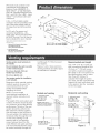
Product dimensions
mMPORTANT:
[]
mnstaHer: Leave hstaHation Unstructions with
the homeowner_
[]-[]
Installation steps
[_]o[]
Use and Care Information
Homeewner: Keep Installation hstructions for
future reference,
Save Installation Unstructions for UocaU
eUectdcaU
inspector's use,
628013A/9763369
- []
[]
[_-[]
Venting requirements
Warranty
Requesting Assistance
or Service
Yoursafetyandthe safetyof
othersis very important.
Wehaveprovided
manyimportant
safetymessages
inthismanual
and
onyourappliance.
Always
readand
obeyatlsafetymessages.
Thisisthesafetyalertsymbol.
Thissymbol
alertsyouto
potential
hazards
thatcankill
orhurtyouandothers.
Alisafety
messages
wiiifoliowthesafety
alert
symbol
andeithertheword"DANGER"
or"WARNING".
These
wordsmean:
You Ganbe killed or seri0usly injured
if you don't f011owinstructions.
AIi safety messages wili teli you what
the potentiai hazard is, teii you how to
reduce the chance of injury, and tell
you what can happen if the
instructions are not followed.
important:
Observe all governing
codes and ordinances.
Proper instaUadon is your
responsibility.
Make sure you have
everything necessary for correct
instaUation, It is the responsibility
of
the installer to comply with the
clearances specified.
Check the location where the range
hood will be instalbd.The
location
should be away from strong draft
areas, such as windows, doors, and
strong heating vents.
Mobile home installation
The installation of this range hood
must conform to the Manufactured
Home Construction Safety
Standards, Titb 24 CFR, Part 328
(formerly the Federal Standard for
Mobile Home Construction and
Safety, Title 24, HUD, Part 280 or
when such standard is not
applicable, the Standard for
Manufactured
Home Installation
1982 (Manufactured
Home Sites,
Communities and Setups) ANSi
A225.1/NFPA 501A*, or latest edition,
or with local codes.
WARNING -- TO REDUCE THE
RiSK OF FIRE, ELECTRIC
SHOCK, OR iNJURY TO
PERSONS, OBSERVE THE
FOLLOWING:
Parts supplied:
amurainura mesh filter
* baffle pmateIvented
installations}
_3-1/4"× 10"18.3x25.4era)damper/vent
connector
Installation work and electrical
wiring must be done by qualified
person(s) in accordance with all
applicable Codes and Standards,
including Fire Rated Construction.
Sufficient air is needed for proper
combustion and exhausting of
gases through the flue (chimney)
of fuel burning equipment to
prevent back drafting. Follow the
heating equipment
manufacturer's guideline and
safety standards such as those
published by the National Fire
Protection Association (NFPA),
and the American Society of
Heating Refrigeration and Air
Conditioning Engineers
(ASHRAE), and the local code
authorities.
When cutting or drilling into wall or
ceiling, do not damage electrical
wiring and other hidden utilities.
Ducted fans must always be
vented to the outdoors.
WARNING -- To reduce the risk
of fire, use only metal ductwork.
This unit must be grounded.
This hood is
installations.
installations,
No. 4396388
factory set for vented
For non=vented
purchase Filter Kit
from your dealer.
materials needed
for installation:
fiat hmade
screwdriver
_ 14/4" (3.0 cm}
drill hit
pmiers
drill
_ I/8" (or 3 fatal drill
bit for pilot homes
ruiner
_ pencil
compass or 8"
120.3 era} eircme
terapmate
• raetamsnips
• keyhome saw
® saber
you amso need:
• duct tape
" 7" 117.8era) round
damper if using
7" 117.8era) round
vent system
saw
Cabinets with
7" 117.8era} round adapter
important: Observe all governing
codes and ordinances.
it is the customer's
responsibility:
,, To contact a qualified electrical
installer.
• To assure that the electrical
installation is adequate and in
conformance with National
Electrical Code, ANSI/NFPA 70
-- latest edition*, or CSA
Standards C22.1-94, Canadian
Electrical Code, Part 1 and
C22.2 No,O=M91 =latest
edition** and all local codes
and ordinances.
A separate ground wire must be
used. it is recommended that a
qualified electrician determine that
the ground path is adequate.
A 120-volt, 60-Hz, AS-only, fused
electrical system is required. A
separate 15=amp circuit is
recommended.
Do not ground to a gas pipe.
Check with a qualified electrician if
you are not sure range hood is
properly grounded.
Tools and
For vented installations,
parts hag
recessed bottoms:
2, 2" 15.8 era} wide filler strips. Length and
thickness determined by recess diraensions.
4 wood screws or fiat head raachine screws
with washers and nnts to attach filler strips.
Do not have a fuse in the neutral or
ground circuit.
IMPORTANT:
Save installation instructions for
electrical inspector's use.
The range hood must be connected
with copper wire only.
The range hood should be
connected directly to the fused
disconnect (or circuit breaker) box
through flexible armored or
nonmetallic sheathed copper cable.
A U.L.° or C.S.A.=listed strain relief
must be provided at each end of the
power supply cable. Wire sizes
(COPPER WIRE ONLY) and
connections must conform with the
rating of the appliance as specified
on the model/serial rating plate.
Wiresizesmustconformto the
requirements
of theNafionaU
EbctdcaU
CodeANSU/NFPA
70=
Uatest
edition_,or CSAStandards
C22.1=94,
Canadian
EUectricaU
Code
Part1andC22.2No.0-M91=Uatest
edition_ andaHbcaUcodesand
ordinances.
A U.L°or C.S.A.°listed
conduit
connectormustbeprovidedateach
endofthepowersupplycame(at
the rangehoodandatthejunction
box).
in U.S.only:Forpowercord
connected
installations,
a U.L°
listedrangehoodcord=connection
IdtMUSTbeused.Cordkithasnot
beenevaluatedfor usein Canada.
Copies of the standards
obtained from:
listed may be
National Fire Protection Association
One Batterymatah
Park
Quincy, Massachusetts 02269
*_ CSA IntematienaU
8501 East PieasantVaHey Road
Cleveland, Ohio 44131°5575
Venting system must terminate to
the outside.
roof through 7" (17.8 cm) round
vent system.
Do not terminate the vent in an attic
or other enclosed space.
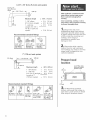
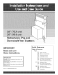
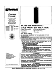
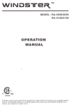
Figures 1 and 2 show, common
venting methods and what types
of materials are needed.
Do not use fouroinch (10.2 cm}
laundry-type wall caps.
Recommended
Do not use plastic vent.
Vent system needed for installation
is not included.
Determine which outside venting
method needs to be used. It is
recommended
that the vent
system be installed before
installing
the hood.
NOTE: if a non-vented
(recirculating)
installation is
desired, follow, instructions on
Page 5.
The length of the vent system and
number of elbow, s should be kept
to a minimum to provide efficient
performance.The
size of the vent
system should be uniform. Do
Not install two elbows together.
Use duct tape to seal all joints in
the vent system. Vent system can
terminate either through the roof
or wall. Use caulking to seal
exterior wall or roof opening
around exhaust hood. For the
most efficient and quiet operation,
it is recommended that the range
be vented vertically through the
Vertical roof venting
7" (17,8 cm} round
or 3-1/4" x 10"
(8,3 x 2&4 cm)
...
"--
Figure 1
roof
J
cap
vent bngth
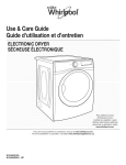
Use 3-1/4" x 10" (8.3 x 25.4 cm)
with a maximum length of 50 ff
(15.2 m) or 7" (17.8 cm) round
vent with a maximum length of
60 ft (27.9 m) for vent system. For
best performance, use no more
than three 90 ° elbows.To
calculate the length of system
you need, add the equivalent feet
(meters) for each vent piece used
in the system. See the examples
on the next page.
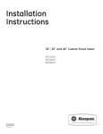
3ol/4"
× 10" (8.3 × 25.4 cm) vent system
3=1/4" × 10"
(8,3 x 2&4 cm)
e_bow
_----6
ft. { 1,8 m)----_
I
wall
cap
I
= 50 ft.
Maximum length
1 - 90 ° elbow
2 ft,
(0.6rn)
8 ft. (2.4 m) straight
1 = wall cap
Length of 3=1/4" x
10" (8.3 x 25.4 cm)
system
Recommended
3=1/4" x 10"
(8,3 x 25.4 crn)
90 ° eBbow =
5 ft. (1.5 m)
=
=
=
5ft.
8ft.
Oft.
(15.2 m)
(1.5m)
(2.4m)
(Om)
= 13 ft. (3.9 m)
standard fittings
3=1/4" x 10"
(8.3 × 25.4 cm)
flat eRbow =
12 ft. (3.7 m)
3=1/4" × 10"
(8.3 x 25.4 cm)
wall cap =
0 ft. (0 rn)
S_ide cardboard or hardboard under
range before moving range across
floor to prevent damaging floor
covering.
Cover countertop, cooktop or set-in
range with a thick, protective covering
to prevent damaging them.
® Disconnect
and move
freestanding range from cabinet
opening to provide easier access
to upper cabinet and rear wall. Put
a thick, protective covering over
cooktop, set=in range or
countertop to protect from
damage or dirt.
[] Determine which venting
method (roof or wall venting or
non=venting) you need to use.This
range hood is shipped for non=
vented installation.
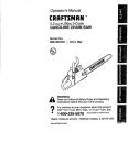
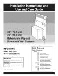
7" (17.8 cm) vent system
Prepare hood
ocation
[_
z_, (0.8 rn)
Recommended
standard
Maximum_ength
=
1 90 ° elbow, s
=
1 =wall cap
8 ft. (2.4 m) straight
Length of 7"
(17.8 cm) system
wood
filler
strips
[recessed
cabinet
bottoms
on_y)
60 ft. t27.g m)
=
=
5 ft.
0 ft.
8 ft.
(1,5 m)
(0 m)
(2,4 m)
=
13 ft.
(3,9 m)
3"
17,8cm)
fittings
wall
[] if cabinet has recessed
90 ° elbow =
5 ft. (1.5 rn)
45 ° elbow =
2.5 ft. (0.8 rn)
7" (17.8 cm)
waBI cap =
0 ft. (0 m)
3ol/4" × 10"
(8.3 x 25.4 cm) to
7" (17.8 cm) =
4.5 ft. (1.4 m)
3=1/4" x 10"
(8.3 x 25.4 cm)
1o7" (17.8 cm)
90 elbow =
511.(1.5m)
bottom, add wood filler strips on
each side. Locate screws to attach
filler strips in locations shown.
®Fromthe diagramsbelow,
sebct the diagramfor your
instalhtion.
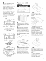
Prepare and install
the hood
Ventedinstallations:
Cut the vent
system and electrical wiring
access hobs as required. Either
wiring hob can be used.
Non=vented installations:
Cut only
the one 1=1/4" (3.2 cm) dia. wiring
access hob required, if wiring
through the top, use Iocadon
shown in VERTICAL vent systems.
if wiring through the back, use
location shown in HORIZONTAL
vent system.
Excessive Weight Hazard
Use two or more people to move
and install range hood.
Failure to do so can result in
back or other injury.
Vertical rectangular vent:
Attach the damper/vent
connection with two screws as
shown.
Insert damper/vent
through
wall
cutout
and
into vent
connection
® Remove terminal box cover.
Depending on your installation,
remove either back or top wiring
knockout.
5-1/2"
(14 sin)
1-1/2"
waH
(3,8 cm)
1-1/4"
(3.2 era) 2"
alia, ho_e (5.1 era)
3-1/4" x 10" (8.3 x 25.4 cm)
RECTANGU LAR VERTICAL
vent system
Remove the rectangular
damper/vent connector from
under the left side of hood. Set
connector and screws aside for
use if connecting to a rectangular
vent system.
center,ins.
8" [20,3 sin)
_._
7-1/2"
For vented installations, go to
Step 7a.
For non-vented
go to Step 7e.
installations,
7C[]
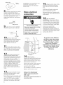
Horizontal rectangular
vent: Attach damper/vent
connection to back of hood and
insert through the wall cutout and
into the horizontal vent.
Note: if the wall cap is directly
behind the vent connector, the
dampers in the wall connector
and cap MUST NOT interfere with
each other. Remove the vent
connector damper if they interfere.
bumps
wall
5"
(12_7 sin)
1-1/4"
(3.2 sin)
dia, ho_e
J_
2 _Y
(&l
F___X
/baffle
sm)
7" (17.8 cm)
vent system
centerHne
7a
[] For vented installations:
Insert the baffle plate into slot
behind grille.The Iocator bumps
should be at the top as shown.
(1&1 sin)
3ol/4" x 10" (8.3 x 25.4 cm)
vent system
Remove either top or rear
rectangular vent knockout. If
using round vent, remove both
top rectangular and semi-circular
knockouts.
Vertical round vent:
Fasten the round adapter to the
hood with two screws as shown.
Install round damper (purchased
separately).
7e[]
For non-vented
installations: Check that the baffle
plate has not been installed in
slot behind grille, if it has,
remove the baffle plate
keyhole
s_ot
front
installations, one end of the vent
connector may need to be
trimmed to clear the electrical
strain relief.
of hood
® Lift the range hood up under
cabinet and determine finaU
position. Mark on the underside
of cabinet the Uocadon of the four
keyhob mounting sbts. Set
range hood aside on a protected
surface.
drill
pilot
Make electrical
hobs
as shown.
Reinstall
light lens. Depress
both
sides of lens, insert tabs into slots
and release.
For non-vented
installations:
Grasp tab at front
center of filter. Push toward back
to release filter from spring clips
at front. Puil down then froward
to remove aluminum mesh filter.
Electrical Shock Hazard
and drill 4 pibt
Install two 40 watt (maximum)
type Aq5 appliance bulbs.
6[]
hole
® Use 1/8" (or 3 ram) ddH bit
5® Depress both sides of the
light lens until tabs disengage
from slots in hood and remove
lens.
Disconnect power before making
electrical connections.
Connect ground w{re to green
ground screw in terminal box.
Failure to do so can result in
death or electricaJ shock.
Install non-vented filter
(purchased separately) by
inserting into channel at back of
compartment.
Grasp tab and pull
forward so that filter snaps under
spring dips at front.
1/4"
(6.4 rnm)
I
O.
To get the most efficient
use from your new range
hood, read the "Use and
Care mnformation"
section.
Keep your Whirlpool
mnstaHation instructions
and
Use and Care Guide close
to range hood for easy
reference.
Remove the 4 hood
mounting screws from the parts bag
and install in pilot hoUes. Leave
screw' heads away from shim
strips about 1/4" (6.4 cm)
1[] if using direct wiring, make
sure power is disconnected, and pull
about 12" (30 cm) of wire through
wail or cabinet and into opening.
2[]
Lift range hood into final
position, feeding electrical wire
through wiring opening. Position the
range hood so that the large end of
the keyhole slots are over the
screws.Then
push the hood toward
the wail so that the screws are in the
neck of the slots.Tighten
mounting
screws to cabinet, making sure
mounting
screws are in narrow neck
of slots. Make sure that damper
blade, if used, rotates up and down
freely.
green
groun¢
screw
14"[] Directwiring:
Connect the white and black wires
of the power supply cable to the
white and black leads in the hood
with twist-on connectors.
Connect the power supply ground
wire to the green ground screw'
inside the terminal bex.
Use caulking
to seal wire opening.
Replace terminal
13m
Connect
ventwork
to hood.
Seal joints with duct tape to make
the secure and air tight.
Note: Damper/vent
connector
and
round vent plate can be installed
up to 1/2" (12.7 ram) on either
side of hood center if ventwork
is
off-center,
in extreme
off-center
box cover.
Using a U.L.-listed power
supply cord-connection
kit
(U.S. only}:
FoHew Power Cord }(it instructiens for
connecting wi_ng.
WARNING
--To reducetheriskof
fireor ebctrbalshock,do notuse
thisfanwithanysolidostate
speed
controldevice,
WARNING
-- TO REDUCE
THE
RiSKOFFIRE,ELECTRIC
SHOCK,ORiNJURYTO
PERSONS,
OBSERVE
THE
FOLLOWING:
Usethisunitonlyin themanner
intendedbythemanufacturer,
if you
havequestions,contactthe
manufacturer.
Beforeservicingor
cleaningunit,switchpoweroffat
servicepanelandlockswitchpower
offat servicepanelandlockservice
panelto preventpowerfrombeing
switchedonaccidentally,
Whenthe
servicedisconnecting
means
cannotbe locked,securelyfastena
prominentwarningdevicesuchas
a tagtotheservicepanel,
CAUTION:
Forgeneralventilating
useonly,Donotusetoexhaust
hazardous
or explosive
materials
andvapors,
WARNING
-- TOREDUCE
THE
RiSKOFA RANGETOPGREASE
FIRE:
Neverleavesurfaceunits
unattended
athighsettings.
Boilovers
causesmokingand
greasyspillovers
thatmayignite.
Heatoilsslowlyonlowor medium
settings.
tray,thenturnofftheburner,BE
CAREFUL
TOPREVENT
BURNS,
if theflamesdonotgoout
immediately,
EVACUATE
AND
CALLTHEFiREDEPARTMENT,
NEVERPiCKUPA FLAMINGPAN
--You maybe burned,
DONOTUSEWATER,including
wetdishcloths
or towels-- a violent
steamexplosion
will result,Usean
AlwaysturnhoodONwhencooking extinguisher
ONLYif:
athighheator whencooking
Youknowyouhavea ClassABC
flamingfoods.
extinguisher,
andyoualreadyknow
Cleanventilating
fansfrequently.
howto operateit,
Greaseshouldnotbeallowedto
Thefire is smallandcontained
in
accumulate
on fanorfilter.
theareawhereit is started,
Useproperpansize.Alwaysuse
Thefiredepartment
is beingcalled.
cookware
appropriate
forthe sizeof Youcanfightthefirewithyourback
thesurfaceelement.
toan exit.
WARNING
-- TOREDUCE
THE
RiSKOFiNJURYTOPERSONS
iN
THEEVENTOFA RANGETOP
GREASEFIRE,OBSERVE
THE
FOLLOWING:
SMOTHER
FLAMES
witha closeo
fittinglid,cookiesheet,or metal
o@ @-b
O
@
.
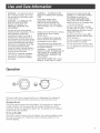
For best results, turn range hood fan on at beginning of cooking and
allow it to run until all smoke and odors are removed from room,
The FAN control is shown in the off position. To turn the fan on, rotate the
control clockwise. The fan speed wiii start at high. Rotating the control
clockwise wiii vary the speed from high to low. The speed can be changed
anytime during fan operation.
To turn on the light:
The LIGHT control is shown in the off position, For maximum lighting, rotate
the control clockwise 45 °, Rotate the control clockwise another 45 ° for
minimum lighting,
3. Give theTeUesaUes
Representative the part
number needed.
Care of range
hood
Aluminum
mesh
and a
When it's time to reptace your
aluminum filter or charcoal fiJter pads:
1. For modeU series
RH4836:
Order AUuminum
no. 4396387.
Non-vented
Order
RH4830
and
FHter
instaUUations:
FHter kit no. 4396388.
2. CaUUWMrUpooU'sTeUesaUes
at 1-800-442-9991.
Clean he range hood with a mild
detergent
and soft cloth. Do not
use abrasive
cleansers
or steel
4. The Representative wHUgive
you the current price.
filters:
CUean often using hot water
mild detergent.
FHters are
dishwasher
safe.
To clean hood:
Uine
wool
pads.
5. PUace your order using your
Master Card _R>,
Visa _ or
Discover _ credit card.
6. If you wish: mail a check or
money order to:
Whirlpool Corporation
1900 Whirlpool Drive
LaPorte, IN 46350-9980
Attn: Accessory Accounting
7. Be sure to ask theTelesales
Representative about the wide
variety of other Whirlpool
Product Accessories.
WHIRLPOOLCORPORATIONMAJORAPPLIANCEWARRANTY
ONE YEAR LIMITED WARRANTY
For one year from the date of purchase, when this major appliance is operated and maintained according to instructions attached to or
furnished with the product, Whirlpool Corporation or Whirlpool Canada LP (hereafter "Whirlpool") will pay for FSP replacement parts
and repair labor to correct defects in materials or workmanship. Service must be provided by a Whirlpool designated service company.
ITEMS WHIRLPOOL
WILL NOT PAY FOR
1.
Service calls to correct the installation of your major appliance, to instruct you how to use your major appliance, to replace or repair
house fuses or to correct house wiring or plumbing.
2.
Service calls to repair or replace appliance light bulbs, air filters or water filters. Those consumable parts are excluded from warranty
coverage.
Repairs when your major appliance is used for other than normal, single-family household use.
3.
4.
Damage resulting from accident, alteration, misuse, abuse, fire, flood, acts of God, improper installation, installation
accordance with electrical or plumbing codes, or use of products not approved by Whirlpool.
5.
Any food loss due to refrigerator or freezer product failures.
6.
Replacement
7.
Pickup and delivery. This major appliance is designed to be repaired in the home.
8.
Repairs to parts or systems resulting from unauthorized
9.
Expenses for travel and transportation
not in
parts or repair labor costs for units operated outside the United States or Canada.
modifications
made to the appliance.
for product service in remote locations.
10. The removal and reinstallation of your appliance if it is installed in an inaccessible
published installation instructions.
location or is not installed in accordance
with
DISCLAIMER OF IMPLIED WARRANTIES; LIMITATION OF REMEDIES
CUSTOMER'S SOLE AND EXCLUSIVE REMEDY UNDER THIS LIMITED WARRANTY SHALL BE PRODUCT REPAIR AS PROVIDED
HEREIN. IMPLIED WARRANTIES, INCLUDING WARRANTIES OF MERCHANTABILITY OR FITNESS FOR A PARTICULAR PURPOSE,
ARE LIMITED TO ONE YEAR OR THE SHORTEST PERIOD ALLOWED BY LAW. WHIRLPOOL SHALL NOT BE LIABLE FOR
INCIDENTAL OR CONSEQUENTIAL DAMAGES. SOME STATES AND PROVINCES DO NOT ALLOW THE EXCLUSION OR LIMITATION
OF INCIDENTAL OR CONSEQUENTIAL DAMAGES, OR LIMITATIONS ON THE DURATION OF IMPLIED WARRANTIES OF
MERCHANTABILITY OR FITNESS, SO THESE EXCLUSIONS OR LIMITATIONS MAY NOT APPLY TO YOU. THIS WARRANTY GIVES
YOU SPECIFIC LEGAL RIGHTS AND YOU MAY ALSO HAVE OTHER RIGHTS, WHICH VARY FROM STATE TO STATE OR PROVINCE
TO PROVINCE.
Outside the 50 United States and Canada, this warranty does not apply. Contact your authorized Whirlpool dealer to determine if
another warranty applies.
If you need service, first see the "Troubleshooting" section of the Use & Care Guide. After checking "Troubleshooting," additional help
can be found by checking the "Assistance or Service" section or by calling Whirlpool. In the U.S.A., call 1-800-253-1301. In Canada,
call 1-800-807-6777.
8/05
if you need assistance
or service
Call the Whirlpool Customer interaction
Center toHofree at 1o800o253o1301.
Our consuitants are avaHabie to assist you.
When calling: PUease know the purchase date, and
_
of your appUiance This information w,HU
heUp us better respond to your request.
the compUete modeU and seriaU number
Our consultants provide assistance with:
® Features and specifications on our full Uine
of appUiances
® installation information
ff you need replacement
if you need to order replacement parts, we recommend that you only use factory-authorized
parts.
These parts will fit right and work right, because
they are made to the same exacting specifications
used to build every newWhirlpool
appliance.
For further
assistance
if you need further assistance, you can write to ask
any questions or tell us about your concerns at:
Customer interaction Center
c/o Correspondence
Dept.
2000 North M-63
Benton Harbor, MI 49022-2692
Please include a daytime
correspondence.
phone number
in your
in U.S.A.
® Use and maintenance
procedures
® Accessory
and repair parts sales
® Specialized
customer
assistance
(Spanish
speaking,
hearing
impaired,
limited
vision, etc.)
® Referrals to local dealers,
service companies,
and
repair parts distributors
Whirlpoolodesignated
service technicians are trained to
fulfill the product warranty and provide afterowarranty
service, anywhere in the United States.
To locate the designated
area, you can also look
Yellow Pages.
service company
in your telephone
in your
directory
parts
To locate factory-authorized
parts in your area, call
our Customer interaction Center telephone number,
your nearest authorized service center, orWhirlpool
Factory Service at 1800-442-1111.
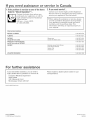
If you need assistance
or service in Canada
1. if the problem is not due to one of the items
listed in "Check Operation"t_.
Contact the deabr from whom you
purchased your appUiance, or call the
IngUis Limited Consumer Assistance
Centre toll-free,
8:30 a.m.- 6 p.m. (EST),
at 1 800-235@665.
Direct service
BBmSH
2. if you need servicer...
Contact your nearest UngUisLimited AppUiance
Service branch or designated servicing outlet to
service your appUiance. (See Uist bebw.)
tWhen asking for assistance or service, please
provide a detailed description of the problem,
your appliance's complete model and serial
numbers, and the purchase date.This
information will help us respond properly to
your request.
branches:
COLUMBIA
1-800-668-8788
ALBEBTA
1-800-661-829!
ONTABIO
Ottawa area
1-800_267-3486
(except
Outside the Ottawa area
1-800-807-8777
807 area code}
MANITOBA, SASKATCHEWAN
and 807 area code in ONTARIO
QUEBEC
ATLANTIC
PBOVmNCES
For further
1-800-668-1683
Montreal (except South Shore)
South Shore Montreal
1-800-36!-3032
1-800-361-0980
Quebec City
Sherbrooke
1-800-463-!523
1-800-867-8988
1-800-565-1598
assistance
if you need further assistance, you can write to
Inglis Limited with any questions or concerns at:
Please include a daytime phone number in your
correspondence,
Consumer Relations Department
Inglis Limited
1901 Minnesota Court
Mississauga, Ontario L5N 3A7
wwwJ nglislimited.com
628013A/9763369
._ 2005 WhirJpooJ Corporation
Printed in U.S.A.
09/2005