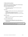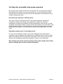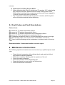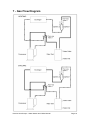
1
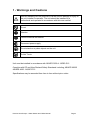
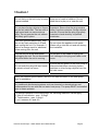
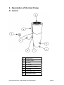
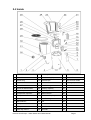
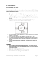
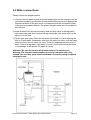
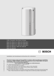
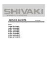
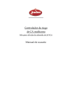
Premier Heat Pumps
Water Heater & Chiller User Manual
Essential Notes on Acceptance and Installation
of the Premier Heat Pumps (PHP) Water Heater
and Chiller
1) Delivery: After removing the transport packaging please check
the PHP Water Heater for any possible damage attributable to
shipping. Any degradation related to transport should be
advised within 48 hours.
2) Important: Please fully read the installation instructions prior to
installation. Installation should only be carried out by suitably
qualified electrician and/or authorised installer. These
instructions should be retained for future reference.
3) Standards of Installation: The installation must be carried out
in accordance with the applicable local safety and installation
standards. The installation must be in accordance with the
manufacturer’s installation instructions; a person qualified in the
installation of Premier Heat Pump Hot Water Cylinders.
Incorrect installation can cause injury to persons or damage to
the unit. The supplier cannot be responsible for incorrect
installation or any resulting damage or injury.
4) Intended Operation: This heat pump is intended to be used as
a domestic hot water cylinder. Any other use or application will
void the warranty.
5) Breakdown: In the unlikely event of failure, contact the installer.
There are no operator serviceable parts and all repairs should
be undertaken by a refrigeration engineer or other authorised
technician.
6) Resale: In the event of resale to a third party, it is imperative
that all manuals and warning and cautions be made available to
the new owner.
Premier Heat Pumps – Water Heater and Chiller Manual
Page 2
Content
ESSENTIAL NOTES ON ACCEPTANCE AND INSTALLATION OF THE
PREMIER HEAT PUMPS (PHP) WATER HEATER AND CHILLER
2
Content
3
1 - Warnings and Cautions
4
! Caution !
5
2 - Description of the Heat Pump
2-1 Outside
2-2 Inside
2-3 Dimensional and Technical Characteristics
6
6
7
8
3 - Installation
3-1 Locating the Unit
Caution
3-2 Water connections
3-3 Electrical Connections
3-4 How the reversible heat pump operates
3-5 Display and Control Screen Description
9
9
9
10
11
12
13
4 - Use in Standard Mode
14
5 - Instructions for the Installer
5-1 Unit controller and parameters
5-2 Defrost operation:
5-3 Fault Codes and Fault Descriptions
16
16
16
17
6 - Maintenance Instructions
17
7 - Gas Flow Diagram
18
8 - Wiring Diagram
20
9 - Problems and Solutions
21
Premier Heat Pumps – Water Heater and Chiller Manual
Page 3
1 - Warnings and Cautions
Incorrect handling has the potential to cause serious damage or injury to
the unit, installer or operator. The unit should be installed by a
professional and operated in accordance with this user manual
Do not
Attention
Confirm electrical connection
Disconnect power supply
Do not stand on or place objects on the unit
Do Not Touch
Unit must be installed in accordance with AS/NZS 3500.4 : NZBC G12
Complies with CE and New Zealand Safety Standards including; AS/NZS 60335
AS/NZS 4692 : AS/NZ 2712
Specifications may be amended from time to time without prior notice.
Premier Heat Pumps – Water Heater and Chiller Manual
Page 4
! Caution !
Do not climb on the unit or try to move
it once installed.
Keep out of reach of children. Do not
allow them to play on or near the unit.
Do not place foreign objects or fingers
into the air inlet/outlet. The fan runs at
high speed and can cause serious
injury. Do not operate the unit without
the safety grill in place.
Important: Ensure that the plug remains
clean, free from moisture, foreign objects
and dirt. Ensure that the plug is properly
inserted or hard wired by a qualified
electrician.
If the unit operates abnormally, stop
the unit by firstly switching it off and
then unplug the unit. For example, if
there is a strange smell or abnormal
noise coming from the unit.
Do not clean the appliance with water.
Water will go into the unit and will destroy
the insulation.
Turn the unit off at the wall before
Do not pull on the cable to unplug the
unplugging the unit. Do not disconnect unit, damage to the plug and cable could
the power while the unit is running.
occur
Do not touch the plug with wet hands,
as electric shock can occur.
Ensure that the power to the heat pump is
disconnected before removing leaves,
particles or other foreign objects from the
air inlet vanes.
Verify the network specifications, with the unit data recorded on the heat pump
prior to installation.
Any additional disinfectant systems, such as chemical or electrolysis are not
recommended for use with this hot water heat pump. The pump MUST be installed
prior to these systems.
For optimal operation of the heat pump, the following maximum values apply:
A. Use of free chlorine : max : 2.6mg/l
B. Total bromine : max : 5.6mg/l
C. pH : between 6.5 and 8.0
Premier Heat Pumps – Water Heater and Chiller Manual
Page 5
2 - Description of the Heat Pump
2-1 Outside
1
Power Plug
2
Control Panel
3
Air Inlet
4
Air Outlet
5
Temperature Sensor
6
Drainage
7
Cold Water Inlet
8
Hot Water Outlet
Premier Heat Pumps – Water Heater and Chiller Manual
Page 6
2-2 Inside
1
Control Panel Cover
15
Four-way Valve 2
29
Top Cover Plate
2
Control Panel
16
Gas Returning Pipe
30
Air Inlet Frame
3
Power Plug
17
Exhaust Pipe
31
Clip of Power Cable
4
Plastic Base
18
Filter
32
Drainage Pipe
5
Water Tank
19
Heat Exchanger Heater
33
6
Cover for Electrical Box
20
Auxiliary Capillary
34
7
Motor Capacitor
21
Capillary
35
8
Compressor Capacitor
22
Defrost Sensor
36
9
Temperature Sensor
23
Condenser Top Poly-foam
37
10
Circuit Board
24
Heat Exchanger
38
11
Electrical Box
25
Fan
39
12
Compressor Heater
26
Fan Motor
40
13
Compressor
27
Motor Bracket
41
14
Four-way Valve 1
28
Rear Net
42
Premier Heat Pumps – Water Heater and Chiller Manual
Page 7
2-3 Dimensional and Technical Characteristics
Model Number
PHP HWC-150
PHP HWC-200
PHP HWC-260
Heating Capacity (KW)
3.2
5.8
6.5
Cooling Capacity (KW)
2.6
4.9
5.7
Nominal Power Input (KW)
0.9
1.48
1.8
Nominal Current (A)
4.2
6.8
8.4
Maximum Current (A)
6.3
8.4
12.6
Compressor Quantity
1
1
1
Fan Quantity
1
1
1
Noise dB(A)
47
47
49
Temperature of output
water (°C)
10-55
10-55
10-55
Φ555X 1780
Φ555X 2113
555/530/2085
630/610/1900
630/610/2233
46/49
56/60
70/74
Water Connection (Inch)
1
1
1
Capacity of the water tank
(L)
150
200
260
Power Supply (V/Ph/Hz)
220-240/1/50
220-240/1/50
220-240/1/50
Ambient Temperature (℃)
-7 to +40
-7 to +40
-7 to +40
Electrical Control Way
Mini Computer Intelligent Control
Controller
LCD Display
Wire Control
Yes
Heating and Cooling Water
Yes
Auto-defrosting Function
Yes
Maximum input water
pressure
1550 kpa
Unit Net Dimension (D X H) Φ470 X 1965
Unit Shipping Dimension
(L/W/H)
Net weight / Gross weight
(kg)
* According to climactic conditions
NB: Product sound measurement is tested in the factory before shipping.
“Dimensions and Technical Characteristics” data table shown above is accurate
at the time of publication. Premier Heat Pumps reserves the right to amend the
unit specifications without prior notice. Product code plate affixed to the
individual unit reflects the specifications of the individual unit.
Premier Heat Pumps – Water Heater and Chiller Manual
Page 8
3 - Installation
3-1 Locating the Unit
It is important to install the hot water heat pump in accordance with the following
instructions. Water and electrical connections must be carried out by a suitably
qualified tradesman or installer
•
•
•
•
•
•
•
The appliance must be installed outside.
The appliance must be mounted on its anti-vibratory studs, positioned on
a substantial platform (concrete or steel pad). The platform must have
sufficient height to prevent water entering the bottom of the unit and also
allow the condensate to drain freely from the connection at the bottom of
the unit
Vegetation and other obstacles must be kept clear of the unit, in
accordance with the minimum distances detailed below
The unit should be positioned so that the exhaust does not blow towards
windows or doorways.
There must be a minimum clear distance above the unit of 1.5m
The stability bracket on the back of unit must be securely fixed to a post
or wall so as to position the unit vertically and prevent any movement of
the unit.
Connect the drain pipe to the condensate outlet and direct it away from
the unit.
Caution
•
•
•
•
Do not install the appliance in an area where dirt, mud, mown grass or
other foreign objects could affect airflow around the unit causing damage
or operational issues.
Shelter the unit from prevailing winds
Shelter the unit from falls of snow or heavy rain fall
Prevent children from playing on or around the unit
Premier Heat Pumps – Water Heater and Chiller Manual
Page 9
3-2 Water connections
Please refer to the diagram below:
1) Connect the hot water in pipe (hot water supply pipe) to the outlet port on the
hot water cylinder. Pay attention to heat preservation and ensure appropriate
thermal insulation of the pipe work. It is important that the unused hot water
outlet port be properly capped. The plastic transport caps are not suitable for
this function.
2) Install a water filter (where necessary) and one-way valve in the tap water (
inlet water pipe) and then connect the tap water pipe (inlet water pipe) to the
inlet port on the tank.
3) Fill the tank with water. Open the tap water (inlet water) in-valve allowing the
tank to fill with water; Meanwhile, open the hot water out-valve, until the water
spills over from the hot water out valve. Once this happens the tank is full of
water. Close the tap water (inlet water) in-valve, check and ensure that there
is no leakage in the system. Re open all valves.
Attention: Be sure the tank is full of water before it is switched on.
Warning: The inlet and outlet plastic caps are for transport only. Any
unused inlet or outlet ports must be blanked off properly using compliant
metal pipe caps.
Premier Heat Pumps – Water Heater and Chiller Manual
Page 10
3-3 Electrical Connections
CAUTION: before connecting the appliance, make sure that the supply
power line is disconnected from the network.
General Power Supply Characteristics
•
Neutral mode TT and TN.S; the circuit of the heat pump must be
connected to the earth circuit
Connections
•
•
•
The electric installation must be carried out by a qualified professional or
electrician
The power supply of the heat pump must come from an independent
circuit and have the appropriate circuit protection.
The controller must be installed on an indoor wall in an easily accessible
area.
Electrical Protection
•
•
Circuit breaker curves D or standard fuse protection Am, gauged with
16A
Differential protection of 30mA
Connection to an Electrical Plug
•
•
The heat pump comes packaged with an electric cable and plug.
The plug must be safe, protected from rain and water and the condition
checked regularly
Before starting the heat pump hot water cylinder, it is important to fully read this
manual and understand the operation and the settings.
Premier Heat Pumps – Water Heater and Chiller Manual
Page 11
3-4 How the reversible heat pump operates
By using the free energy contained in the ambient air, the heat pump enables
the heating of the water in a very economical way. Your heat pump is a heat
machine that can transfer the heat from a low temperature area (ambient air) to
a higher temperature area.
How the pump operates in heating mode:
The heat of the air is absorbed by the cold, liquid refrigerant, through the
evaporator (radiator with wings), the refrigerant is vaporised. Then the
compressor increases the pressure and the temperature, and sends it into the
condenser (exchanger) where it loses its heat by transferring it to the water. The
refrigerant then returns to the liquid state, it loses its pressure and cools again,
flowing into the pressure reducer before returning to the evaporator for a new
cycle.
Operating cooling mode or defrosting mode:
A 4 way valve enables a reverse cycle of the refrigerant; this fluid liquid is
vaporized in the exchanger (the evaporator) by taking the heat out of the water,
which then passes into the compressor that heats it and in turn sends it to the
radiator (the condenser) where the refrigerant returns to it's liquid state.
Note: Single water heater without cooling water mode; Single water chiller
without heating water mode and defrosting mode.
Premier Heat Pumps – Water Heater and Chiller Manual
Page 12
3-5 Display and Control Screen Description
Premier Heat Pumps – Water Heater and Chiller Manual
Page 13
4 - Use in Standard Mode
Starting operation
Press the power button
when the unit has received the signal it gives out
two 'beep' tones. The operation light switches on and the heat pump water
heater starts operation. The compressor will restart after 3 minutes to protect
the system if the interval is shorter than 3 minutes from the last shut down to the
present switch on.
Mode Selection
Press the 'M' button to chose the mode of heating and cooling (this key is
invalid for the single water chiller or single water heater)
Temperature Setting Selection
1) Press "Temperature Adjustment Button
degree higher
to set the temperature 1
2) Press "Temperature Adjustment Button
degree higher
to set the temperature 1
3) Temperature range is set in heating mode: 45°C to + 55°C (Single water
chiller is without this function)
4) Temperature range is set in cooling mode: 10°C to + 35°C (Single water
heater is without this function)
Timer Switch On
timer-on button to set time for the
1) When the heater is off press the
timer-on switch. Press the button once to change the time interval of 1
hour in a cyclic manner of 1,2,...24,1,2 (The display shows the previous
time as the starting time of the present setting)
2) When it reaches the switch-on time, the heat pump water heater will
operate in the preset time mode.
3) Press the timer-on
button again, and the set up is cancelled.
4) If the on/off
button is pressed while the unit is under the timer on
setting, the unit will start immediately. The timer setting is at that point
cancelled.
Timer-Off Switch
1) When the heater is on, press the
timer-on button to set time for the
timer-on switch. Press the button once to change the time interval of 1
hour in a cyclic manner of 1,2,...24,1,2 (The display shows the previous
time as the starting time of the present setting)
Premier Heat Pumps – Water Heater and Chiller Manual
Page 14
2) When it reaches the switch-off time, the heat pump water heater will
automatically shut down.
3) Press the timer-on
button again, and the set up is cancelled.
button is pressed while the unit is under the timer-off
4) If the on/off
setting, the unit will shut down immediately. The timer setting is
cancelled.
5) Timer-On and Timer-Off cannot be set at the same time.
Coercive Defrosting
1) Press the
button, the heater will go into the defrost mode.
2) After 3 minutes, when the units coil temperature has reached 10°C or the
time of defrost reaches 8 minutes, defrosting is stopped.
3) After exiting the defrost mode, the heater will stop operation for 3
minutes, then it will run in the mode before defrosting. (This key is invalid
for single mode water chiller)
Premier Heat Pumps – Water Heater and Chiller Manual
Page 15
5 - Instructions for the Installer
The installer must read the following and provide instructions to the purchaser.
5-1 Unit controller and parameters
The Heat Pump is Equipped with 2 Control Devices:
•
•
•
A defrost temperature probe, located on the evaporator, starts the defrost
sequence.
A thermal probe located on the exchanger ensures the cut of the heat
pump when the temperature of the water reaches the temperature
required.
The meaning of the code name
T1: water temperature
T2: ambient temperature
T3: exhaust temperature from compressor
T4: coil temperature in outdoor heat exchanger
TC: water temperature setting
Control Function:
1) TC can be set between 10C-35°C in cooling mode. Original TC is 18°C.
When T1≤T°C -1°C, Compressor and fan motor stop; When T1≥T°C
+1°C, Compressor and fan motor start.
2) TC can be set between 45°C -60°C in heating mode. Original TC is
50°C. When T1≤TC-1C, Compressor and fan motor start; When
T1≥TC+1C, Compressor and fan motor stop. When compressor is
running, if T2≤12°C, the four way valve2 on; if T2≥12°C, the four way
valve2 off.
5-2 Defrost operation:
1) Defrost:
The system begins to defrost if the following three terms are met in the
same time:
a) T4≤-5°C lasts for a while;
b) compressor runs continuously for more than 5 minutes
c) Compressor runs accumulative total for 45 minutes
While the system begins to defrost, compressor and fan motor stop first and
four way valve1 is on after 1 minute and begins to work. The compressor
restarts after it has stopped for 3 minutes. If the sensor for T4 is damaged, the
system begins to defrost, after the compressor has run continuously for 45
Premier Heat Pumps – Water Heater and Chiller Manual
Page 16
minutes.
2) Parameters for Exiting Defrost Mode:
• When defrosting time reach 3 minutes and T4 reaches 10°C or defrosting
time reaches 8 minutes, defrost exits and starts heating water mode.
While defrost is exiting, after compressor and fan motor have stopped for
1 minute, the four way valve1 is turned off.
• The Compressor will restart after it stops for 3 minutes, and the system
will run the same mode as before defrosting.
5-3 Fault Codes and Fault Descriptions
Failure Code:
E1: sensor for T1 (water temperature) failure
E2: sensor for T2 (ambient temperature) failure
E3: sensor for T3 (exhaust temperature from compressor) failure
E4: sensor for T4 (coil temperature in condenser) failure
E5: Compressor stops three times in 24 hours because the current is too high.
E6: While heating water, there is three times of T3≥100°C in 24 hours.
E7: There is electrical leakage in the compressor or outdoor motor or four-way
valve
Recommendation: Contact the installer or service agent
6 - Maintenance Instructions
The following operational maintenance must be done by a qualified person each
year:
•
•
•
•
•
•
Clean the back evaporator with a delicate brush and water jet without
any pressure (karcher prohibited)
Check the mandatory labelling and the operation of the unit
Check the safety measures
Check the pressure of the refrigerating gas
Clean the electric box and control the connections
Check the electrical connections
Premier Heat Pumps – Water Heater and Chiller Manual
Page 17
7 - Gas Flow Diagram
Premier Heat Pumps – Water Heater and Chiller Manual
Page 18
Premier Heat Pumps – Water Heater and Chiller Manual
Page 19
8 - Wiring Diagram
Premier Heat Pumps – Water Heater and Chiller Manual
Page 20
9 - Problems and Solutions
Please refer to the table below for the most common problems. These can often
be solved by reading the table below. If nothing corresponds to the list, or if the
solutions applied do not solve the problem, contact your retailer
Problem
Observation
Probable Cause
Explanation/Solution
The heat pump does
not start
Blank display
No electrical feed or
power supply
Check the plug and
electrical connection.
Check the line circuit
breaker
The heat pump does
not start
Screen on
Low voltage
Find out reason and
repair
The heat pump starts
and stops within a
few minutes
The temperature of
the water heater
increases very slowly
Water is running
under
the heat pump
Refrigerant circuit is
damaged
Water temperature and
ambient temperature too
low Water amount used
continuously too large.
The heat pump works
Water condensate come
from the condenser and
is part of normal
operation
The thickness of the
frost is thin
Attach the plastic
conduit to the black
plastic outlet and direct
the water away from
the unit
Ambient temperature is
too low
Some frost appears
outside, on the wings
of the evaporator
The heat pump
works but the
temperature of the
water does not rise
(*)
Check leakage, charge
refrigerant with correct
amount.
Change compressor
repair damaged
refrigerant circuit
The thickness of the
frost is thick (the
blades of the ventilator
may rub on the ice
much more on the
inside)
The de-icing probe or
the thermic circuit
breaker does not work
The pressure of the
refrigerant shown on
the manometer is very
low
Loss of refrigerant from
the unit
The pressure of the
manometer
is right
Breakdown or abnormal
wear of the compressor
Premier Heat Pumps – Water Heater and Chiller Manual
The condensates are
formed in humid
conditions on the cooling
fins of the evaporator.
Install the conduit to
direct the water away
from the machine
The frost is entailed by
the freezing of the
humid air on the wings
of the evaporator. It's
quite natural and the
heat pump is going to
defrost. Consider the
wintering of the heat
pump.
Stop the heat pump and
call your retailer
Stop the heat pump and
call your retailer or a
refrigeration technician
Page 21