1
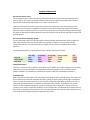
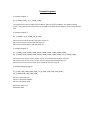
ADEPT User Manual ALine Development Platform ALine integrates pneumatic valves and diaphragm pumps into our planar laminate microfluidic cards. These on-‐card valves and pumps can be reliably controlled with the ALine Development Platform (ADEPT). You can choose to control your microfluidic experiments with any combination of manual or software control. External Connections Power: 6V DC Power supply, 2.1 mm center positive. Air: 30-‐100 PSI air, 1/4” push-‐to-‐connect Vacuum: Vacuum, 1/8” OD push-‐to-‐connect Communications: USB, microSD The air source connection is a push-‐to-‐connect tube fitting, meant to fit firm tubing with an OD of 1/4”. The vacuum source input connection is a push-‐to-‐connect tube fitting, meant to fit firm tubing with an OD of 1/8”, such as McMaster part number 5181K15. System Setup To setup the system for the first time: 1. Plug in the 6V power adapter. 2. Plug in the air and vacuum sources. 3. Plug in the microSD card. 4. Attach tubing between ADEPT and your microfluidic card. 5. Close off any unused outlets on ADEPT with a plug, such as McMaster part number 5111K501. In the default configuration, the outputs switch between air and vacuum, so any outputs that remain disconnected will leak air/vacuum. These plugs can also be cut and used as adapters between the push-‐ to-‐connect sockets and soft tubing. System components On-‐card pneumatic valves The on-‐card pneumatic valves are typically closed with 10-‐20 PSI compressed air and opened with a vacuum source. The valves can operate without using vacuum to pull the valve fully open, but they operate better when switched between an air and a vacuum source. These on-‐card valves are used to control the movement of fluid on the cards. An evaluation of the performance of our valves is available as a technical article. We found that the valves perform best when the valve's actuation pressure is at least five times the pressure of the fluid being pushed through the channel. Operating the onboard valves at a pressure greater than 20 PSI will damage the valves due to delamination. On-‐card pneumatic diaphragm pumps The on-‐card pumps consist of a pneumatically actuated chamber with pneumatic valves on both the inlet and the outlet. The valves and chamber are actuated in sequence to pump fluids through microfluidic channels. The pump elements are closed with air pressure and opened with vacuum pressure. Example pump operation, starting with the inlet, chamber and outlet all closed: Tubing Connections There are a variety of ways to attach a microfluidic card to ADEPT. One simple method uses soft tubing to directly connect to hose barbs or to peek tubing connectors glued into the microfluidic device. Another method is to manufacture a manifold to connect a card to the development platform. Solenoid Valves ADEPT controls the flow of gas to the microfluidic card using miniature solenoid valves. The system can drive a theoretical maximum of 48 solenoid valves, though a typical system will drive 8 to 16 solenoid valves. The solenoid valves have three ports: Normally-‐Closed, Normally-‐Open, and Common. The on-‐ card valves operate best when closed with air and opened with vacuum, so by default, we connect vacuum to all the Normally-‐Open ports and air to all the Normally-‐Closed ports. The Common port connects to the outlets on the front of ADEPT. In this configuration, the solenoid valves output vacuum when they are unpowered and output air when they are powered. The solenoid valves should not have more than 30 PSI of differential pressure between their inputs. Pressurized Reservoirs A simple method to drive fluid through microfluidic channels without using pumps is to pressurize a reservoir, typically with 1-‐3 PSI gas and then to attach the reservoir output to the microfluidic channels. Using a one-‐way valve in the tubing line will prevent the liquid from flowing back when the pressure is turned off. On-‐card valves can control the fluid flow from the reservoir. Using a pressurized reservoir requires fewer valves than a pump and is good for washing steps. Pressure Regulators ADEPT has miniature pressure regulators to regulate the air (10-‐20 PSI recommended) and vacuum lines. The pressure is measured using pressure sensors and displayed on a digital display on the back panel. The digital displays are calibrated using trim potentiometers. These miniature pressure regulators are sufficient to regulate the pressure going to the on-‐card valve and pumps, which are insensitive to small variations of pressure. If your application requires more accurate control of the pressure, we can connect higher-‐accuracy external pressure regulators and pressure gauges. ADEPT User interface We have many options for controlling the ALine Development Platform. All the air outputs can be controlled manually using toggle switches or with a variety of software methods. Manual Control Toggle Switches Each solenoid valve has a three-‐position toggle switch, which allows you to turn the valve ON, OFF or be software controlled. An indicator LED lights up when the valve is actuated. Simple manual control is very useful for troubleshooting and configuration during the development process. You might set three valves that control an on-‐card pump to run a continuous pump cycle via software control, while turning other valves ON or OFF manually. Software Control SD Card The primary method of software control reads a program, program.txt from a microSD card. The program is a description of the behavior of each valve in the system over time, saved as a text file to a microSD card. When ADEPT is turned on or reset, the system reads the program from the SD card and runs whatever valve events you have specified. The valve programs are written in a simple format that describes the sequence of actions you want a valve to perform. For example, a sequence might be defined to turn Valve 1 on for 1 second, then off for 2 seconds. Sequences for each valve can be set to repeat in a loop for a specified number of times, or to loop continuously. Valve events can be accurately timed to occur nearly simultaneously. Adjacent solenoid valves have a delay of less than 150 microseconds between events that are defined to be simultaneous. On a 16-‐valve system, the maximum actuation time delay between 'simultaneous' events is less than 2 ms. The response time of the solenoid valves is approximately 3 ms. Programming ADEPT The easiest way to write an ADEPT program is to use the ADEPT Program Generator Excel spreadsheets. You can also edit a text file directly, according to the following rules: 1. The filename of the program is program.txt. 2. Other files can be on the SD card; they are ignored by ADEPT. 3. You don't have to program the solenoid valves you aren't using. Solenoid valves default to off. 4. Program structure: [Valve1][delimiter][Run Number][delimiter][Event1][delimiter][Event2][delimiter][EventN][delimiter][sequence end character] [Valve2][delimiter][Run Number][delimiter][Event1][delimiter][Event2][delimiter][EventN][delimiter][sequence end character] [Valve3][delimiter][Run Number][delimiter][Event1][delimiter][Event2][delimiter][EventN][delimiter][sequence end character] [Valve4][delimiter][Run Number][delimiter][Event1][delimiter][Event2][delimiter][EventN][delimiter][sequence end character] 5. Valves are specified by V#, i.e. valve one is V1, valve two is V2. 6. The run number is the number of times the pattern should run. A run number of 0 repeats the pattern continuously. A run number of 1 runs the pattern once. A run number of n runs the pattern n times. When a pattern is completed, the valve stays in its final state. 7. Program events can turn a solenoid valve HIGH (on) or LOW (off) for n number of milliseconds. An event to turn a solenoid on for 500 milliseconds is written as H500. Turning a solenoid off for 500 milliseconds is written as L500. 8. You can specify many events (several hundred), up to the memory limits of the microcontroller. 9. All items in the program must be followed by a delimiter character. The delimiter character is an underscore _. 10. The behavior of each valve is written as a sequence of events. Each sequence in the program is followed by a sequence end character. The sequence end character is a dash -‐. Microcontroller programming It is possible to write programs directly for the Arduino microcontroller platform to control the system. This might be useful if you want to integrate additional sensors or conditional control logic. ALine may be able to assist with adding features to the firmware. Example Programs 1. Example program 1. V1_0_H1000_L1000_-‐V2_1_H5000_L5000_-‐ This program turns Valve 1 high (on) for 1000 ms, then low (off) for 1000 ms. This pattern repeats forever. The program also turns Valve 2 on for 5000 ms and then off for 5000 ms. Valve 2 stays off after that. 2. Example program 2. V1_1_H10000_-‐V2_0_H1000_-‐V3_0_L100_-‐ Valve 1 turns on for 10 seconds, then valve 1 stays on. Valve 2 turns on for 1 second and then stays on. Valve 3 turns off for 100 ms and then stays off. 3. Example program 3. V1_1_H1000_L1000_H1000_L1000_H1000_L1000_H1000_L1000_H1000_L1000_-‐ V2_1_H1000_L1000_H1000_L1000_H1000_L1000_H1000_L1000_H1000_-‐V3_0_H1000_L1000_-‐ Valve 1 turns on, off, on, off, on, off, on, off, on, off 1 second each and then stays off. Valve 2 turns on, off, on, off, on, off, on, off, on 1 second each and then stays on. Valve 3 turns on for 1 second, then off for 1 second, and then stays off. 4. Example pumping program. V1_0_L500_L500_H500_H500_H500_-‐V2_0_H500_L500_L500_H500_H500_-‐ V3_0_H500_H500_L500_L500_H500_-‐ Valve 1 is the pump inlet. Valve 2 is the pump chamber. Valve 3 is the pump outlet. Document revision 1.1 September 2013