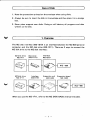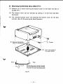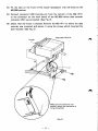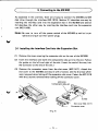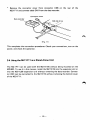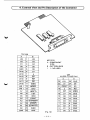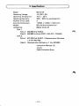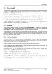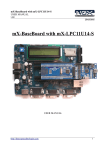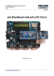
1
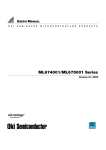
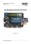
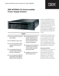
SHARP.
INTRODUCTION
Thank you for bu'y g the MZ-1 E19 SHARP MZ Disk Interface.
Before using the MZ Disk Interface, please read this manual carefully to
assure correct operation.
The contents of this manual are subject to change without notice.
If the product is defective, please contact the store where you bought it.
SHARP is not responsible for damage incurred during, or as a result of,
operation.
CAUTION
1. This unit consists of precision parts, such as LSI circuits, that can be
affected by the operating environment. Do not use the unit in place
subject to direct sunlight, extreme change of temperature or high
humidity or dust.
2. Do not bump or drop this unit.
3. Be careful not to touch the connector with your hand.
Static electricity may destroy certain parts.
4. Special attention must be paid when handling disks.
Refer to the MZ-1 F11 Instruction Manual for details.
5. We recommended that you make a copy of the original master disk
and use the copy. Store the original master disk in a safe place. (Refer
to the MZ Disk BASIC Manual included with this unit for the procedure
for copying a disk.)
C_________________Ca
__~_o_f_D_i_Sk________________~)
1. Note the precautions printed on the envelope when using disks.
2. Always be sure to insert the disk in its envelope and then place it in a storage
box.
3. Never place magnets near disks. Doing so will destroy all programs and data
written on the disk.
C~
_________________1._0_v_e_N_ie_w________________~)
The MZ disk interface (MZ·1 E19) is an interface between the MZ·aOO personal
computer and the MZ disk drive (MZ-1 F11). There are 2 ways to connect the
MZ disk drive to the MZ disk interface:
MZ disk drive
MZ-1F11
MZ disk drive
MZ-1 F11
Slot cover
(MZ-1X17)
Interface
MZ-1E19
Interface
MZ-1 E19
Expansion unit
MZ-1U06
Expansion board
MZ-1E20
When you use the MZ-1 F 11, refer to the MZ DISK BASIC manual included.
-1-
2. Connection
)
C
~---------------------------Follow the procedures below to connect the MZ-800 personal computer and the
MZ disk drive.
1) Removing the Data Recorder
(1) Turn off the power switch of the MZ-800 and pull out the power plug.
Remove the 2 screws securing the data recorder on the left rear side of the
MZ-800. Lift up the data recorder. (See Fig. 1)
(2) Disconnect connector CN1 (connected to the data recorder by cable) from
the main board of the MZ-800. (See Fig. 1 )
Data recorder
CD
Screws
(Fig. 1)
Notes:
* If there is a cover instead of a data recorder, remove the cover.
* If the data recorder is also to be used, connect it to the connector on the
MZ-1 F11. (For details see 3-3 Connecting the Data Recorder.)
-
2-
2), Mounting the MZ Disk Drive (MZ·1 F11)
(1) Remove the 2 screws securing the bottom cover on the lower rear side of
the MZ-1 F11.
(2) The bottom cover can be removed by pulling it to the front and then
downward.
(3) The removed bottom cover now becomes the bottom cover for the data
recorder. (See 3-3 Connecting the Data Recorder.)
1
®_Remove the bottom
cover in this direction
r.:"II,,",",-_ _
@ Fits on the inside of
the upper cabinet
Front
•
I
E!JJ_sZ!ZZZII'ZZZZI_ _P.I'lZt.li9p
®
O
b
Rear
The bottom cover can be removed
from the MZ disk drive by pulling
it to the front and then downward.
(Fig. 2)
-
3 -
(4) Fit the tabs on the front of the louver (accessory) jnto the holes on the
MZ-800 cabinet.
(5) Connect connector CN2 (coming out from the bottom of the MZ-l Fll)
to the connector on the main board of the MZ-800 where data recorder
connector CNl was connected. (See Fig. 3)
(6) Check that the louver is secured. Position the MZ-l Fll to where the data
recorder was mounted and secure it using the screws which mounted the
data recorder. (See Fig. 3)
Louver
Make sure the direction and
position where the connector is
to be connected.
(Fig. 3)
-
4 -
C~
____________3_._Co_n_n_e_d_i~__t_o_th_e_M_Z_._8_00_____________)
As explained in the overview, there are 2 ways to connect the MZ-800 and MZ
disk drive through the interface (MZ-1E19). Section 3-1 describes one way by
inserting the interface card into the expansion slot in the MZ-800 and section
3-2 describes the other way by inserting the interface card into the expansion
unit (MZ-1 U06).
Note: Be sure to turn off the power switch of the MZ-800 as well as its peripherals and pull out their power plugs.
3-1 Installing the Interface Card into the Expansion Slot
(1) Remove the cover covering the expansion slot on the rear of the MZ-800.
(2) Insert the interface card (with the components side up) into the slot. Follow
the guides on the left and right of the slot. (Insert the card all the way into
the connector at the end of the slot.)
(3) Remove the connector cover from the slot cover (MZ-1X17). Attach the
slot cover to the MZ-800 and secure with 2 screws. Use the 2 screws which
were removed when taking off the expansion slot cover. Fasten the MZ-1 E19
with the 2 screws removed when taking off the connector cover.
~-,.a
~
-
-''':~-
.~
•
~ ••
•
(Fig. 4)
-
5 -
-
Guides
Slot cover (MZ-1 X 17)
Connector cover
(4) Insert the connector from the MZ.-1 Fll into the slot. Connect it to the
connector on the interface card, and secure with the 2 attached screws.
Connector CN3
(Fig. 5)
This completes the connection of the MZ-1 F11 and the MZ-800 through the
interface card (MZ-1 E19).
3-2 Connecting with the Expansion Unit (MZ-1U06)
(1) Remove the cover covering the expansion slot on the rear of the MZ-800.
(2) Insert the expansion board (MZ-1 E20) into the slot. Follow the guides on
the left and right of the slot. (Insert the card all the way into the connector
at the end of the slot.)
(3) Use the 2 screws (which held the slot cover) to secure the expansion board
to the MZ-800.
Expansion board MZ-1 E20
(Fig. 6)
-
6 -
"
(4) Remove the cover covering slot number 1 or slot number 2 on the expansion unit (MZ-1U06) and install the interface card (MZ-1E19). Insert the
card along the guides on the left and right of the slot. (Insert the card all
the way into the connector at the end of the slot.)
(5) After removing the connector cover, reattach the cover with the 2 screws.
Fasten the MZ-1E19 with the two screws removed when taking off the
connector cover.
Expansion unit
MZ-1U06
Interface card MZ-1 E19
(Fig. 7)
(6) Connect the connection cable from the MZ-l Fll to the interface connector
installed in the expansion unit. Secure both ends of the connector with
screws.
-
7 -
(7) Connect the connection cable from the expansion unit to the expansion
board (MZ-1 E20) installed in the expansion slot of the MZ-800. Secure
both ends of the connector with the 2 screws.
Expansion unit MZ-1 U06
Expansion board
MZ-1E20
/~
(Fig. 8)
This completes the connection of the MZ-800 and the MZ-1 F11 using the expansion unit.
3-3 Connecting the Data Recorder (See Figs. 5 and 8)
The removed data recorder can still be connected as a stand-alone unit_
*
~~tl:~~~:::~: ctah~eband holding the connector cable on the bottom of the
data recorder. Be sure not to cut the cable.
(Fig. 9)
-
8
~
(1) Stick the provided cable protective sheet on the bottom cover removed
when installing the MZ-l Fll to the main unit (see Fig. 10).
(2) Install the bottom cover with the cable protective sheet to the data recorder.
Be sure to take out the cable from the narrow opening between the cabinet
and the bottom cover by sliding it along the inside of the cabinet (see Fig.
10-1 ).
(3) Fasten the both lower sides of the rear .part with the two screws removed
when taking off the bottom cover of the MZ-l F 11.
Cable protective sheet
Print wired board
-
9 -
* Remove the connector cover from connector CN6 on the rear of the
MZ-1 F11 and connect cable CN1 from the data recorder.
Data recorder
(Fig. 11)
This completes the connection procedures. Check your connections, turn on the
power, and check the operation.
3-4 Using the MZ-1 F 11 as a Stand-Alone Unit
The MZ-1 F11 can be used (with the MZ-1 E19) without being mounted on the
MZ-800. To use it in this manner, install the MZ-1E19 into the expansion slot or
into the MZ-1 U06 expansion unit without removing the data recorder. Connector CN3 ean be connected to the MZ-1 E19 without removing the bottom cover
of the MZ-1 F11.
•
-10-
4. External View and Pin Description of the Connector
)
C---------------~--------~
Slot side
A
I
B
+5V
1
+5V
02
2
03
04
01
3
DO
4
05
GNO
5
06
(A15)
6
07
(A14)
7
(/>
(A13)
8
Ml
(A12)
9
WR
(All)
10
RO
MZ-l E19
A: COMPONENT
SIDE
B : PATTERN SIDE
(
): NO USED
CNl
HU-20P (TO MZ Disk)
A
25
B
+5V
26
Sl
24
CE
RESET 22
SO
GNO
(Al0)
11
(A9 )
12
(A8 )
13
GNO
19
(/>
20
RO
A7
14
17
Ml
18
10RQ
A6
15
(HALT)
(I El)
15
07
16
GNO
A5
16
(lEO)
13
06
14
GNO
A4
17
RESET
11
05
12
GNO
9
04
10
GNO
7
03
8
GNO
5
02
6
GNO
3
01
4
GNO
1
DO
2
GNO
23
10RQ__
21
MREQ
A3
18 (EXRESET)
A2
19
Al
20 (EXWATT)
AO
21
(NMI)
GNO
22
GNO
(EXINT)
(Fig. 12)
-
11 -
5. Specifications
)
C~----------~-------------MZ-1 E19
Model:
+5 VDC± 5%
Operating Voltage:
10°C - 35°C
Operating Temperature:
20% - BO% (no condensation)
Operating Humidity:
3
Number of ICs Used:
116(W) x 144(D) x 19(H) mm
External Dimensions:
B5 g (without accessories)
Weight:
Master Disks (2)
Accessor i es:
Disk 1
Side A: MZ-BOO Disk BASIC
Side B: MZ-BOO Utilities (COPY, DELETE, TRANS)
Disk 2
Side A: MZ-700 Disk BASIC + Demonstration Softwartt
x 2 (for MZ-700)
Side B: Demonstration Software x 1 (for MZ-BOO)
Instruction Manuals (2)
Louver
Cable Protective Sheet
-121
SHARP CORPORATION
OSAKA, JAPAN
Printed in Japan
Gedruckt in Japan
Imprime au Japon
Stampato in Giappone
©1984 SHARP CORPORATION
4J7.5-1-0 TINSE1225ACZZ