1
Solutions for Demanding Applications
VarTech Systems Inc.
Industrial CRT and Flat Panel Displays
VT190PM
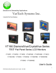
VT190 Military / Marine Series
19.0” Flat Panel LCD Displays
VT190CM · VT190PM · VT190RM
VT190MM · VT190WM · VT190YM
User’s Guide
Read these instructions completely before attempting to operate your new Color Display.
Table Of Contents
Section 1
Page
Introduction
Section 4
Page
Touch screen
About LCD Monitors
1
Touch Screen Introduction
Product Safety Precautions
2
On Safety
2
Section 5
On Installation
3
Troubleshooting Tips
On Cleaning
3
On Repacking
3
17
18
Section 6
Cleaning & Maintenance
19
Section 2
Display Setup
Section 7
Display Features
4
Mechanical Drawings
Unpacking The Display
4
Panel Mount Procedure
20
Included Parts
4
Panel Mount Mechanicals
21
Connecting Your Display
5
Rack Mount Mechanicals
22
5-7
Wall Mount Mechanicals
23
Yoke Mount Mechanicals
24
Signal Connections
Section 3
Getting Started
Operator Controls and Indicators
Setting up the Video Source
Section 8
8
9-10
Adjusting the monitor
11
Navigating the OSD
12
Picture Submenu
13
OSD Submenu
14
Utility Submenu
15
Quick Menu
16
Display Specifications
25
Section
1
1.1
INTRODUCTION
About LCD Monitors
What you gain by using an LCD monitor in your industrial controls
LCDs
are the future of display technology. Although CRTS have dropped in
cost significantly, they do not offer the performance, reliability, and
mounting options available with LCDs. LCD monitors consist primarily of
an LCD, Video Board and a Back Light video. The LCD determines to a
large extent the viewing angle, brightness and contrast. Beyond that it is
the function of the video board which converts the analog RGB (Red, Green, Blue) signals from a
standard video card to a high quality, digital RGB that the LCD can display.
Recently the video card has taken on a new role. It is the responsibility of this device to “scale” a
particular video resolution to the “native” resolution of the LCD. Simply, consider that a computer is
putting out a VGA [640x480] resolution signal, yet the LCD that is connected is an XGA
[1024x768] display. The displayed picture would be in the center 1/3 of the LCD. With the
introduction of the scaling engine. The converter will mathematically recalculate the 640x480 to
1024x768. This may sound simple but it is in fact a complex algorithm that adjusts for different
aspect ratios and pixel alignment, essentially smoothing text and graphics to produce a picture
that is pleasant to the eye.
All Vartech displays from 12.1” (800x600) to 23.1 (1600x1200) incorporate scaling engines in the
converter card.
1
1.2
Product Safety Precautions
This unit has been engineered and manufactured to ensure your personal safety,
however improper use may result in potential electrical shock or fire hazards. In order
to allow the proper operation of all safeguards incorporated in this display, observe the
following basic rules for its installation, use, and servicing.
1.3
On Safety
Use only the power cord supplied with the unit. In case you use another power cord, make sure
that it is certified by the applicable national standards if not being provided by the supplier. If
the power cable is faulty in any way, please contact the manufacturer or the nearest authorized
repair service provider for a replacement. The power supply cord is used as the main
disconnection device. Ensure that them socket-outlet is easily accessible after installation.
Operate the display only from a power source indicated in the specifications of this manual or
listed on the display. If you are not sure what type of power supply you have, consult with your
service or maintenance department. Overloaded AC outlets and extension cords are
dangerous. So are frayed power cords and broken plugs. They may result in a shock or fire
hazard Call your service technician for replacement.
Do not Open the Display.
♦ There are no user serviceable components inside.
♦ There are Dangerous High Voltages inside, even when the power is OFF.
♦ Contact your dealer if the display is not operating properly.
To Avoid Personal Injury :
♦ Do not place the display on a sloping shelf unless properly secured.
♦ Use only a stand recommended by the manufacturer.
♦ Do not try to roll a stand with small casters across thresholds or deep pile carpets.
To Prevent Fire or Hazards:
♦ Always turn the display OFF if you leave the area for more than a short period of time.
♦ Do not drop or push objects into the display's cabinet openings. Some internal parts carry
hazardous voltages.
♦ Do not add accessories that have not been designed for this display.
♦ During a lightning storm or when the display is to be left unattended for an extended period
of time, unplug it from the wall outlet.
Important Precautions
2
1.4
On Installation
Do not allow anything to rest upon or roll over the power cord, and do not place the display
where the power cord is subject to damage.
Do not use this display near water such as near a sink, in a wet location where there is
standing water. Displays are provided with ventilation openings in the cabinet to allow the
release of heat generated during operation. If these openings are blocked, built-up heat can
cause failures which may result in a fire hazard.
Therefore, NEVER:
♦ Block any ventilation slots.
♦ Place the display in a built-in enclosure unless proper ventilation is provided.
♦ Cover the openings with cloth or other material.
♦ Place the display near or over a heat source.
Do not rub or strike the Active Matrix LCD with anything hard as this may scratch, mar, or
damage the Active Matrix LCD permanently.
Do not press the LCD screen with your finger for a long time as this may cause some
afterimages.
Some dot defects may appear as Red, Green or Blue spots on the screen.
However, this will have no impact or effect on the display performance.
If possible, use the recommended resolution to obtain the best image quality for your LCD
display. If used under any mode except the recommended resolution, some scaled or
processed images may appear on the screen. However, this is characteristic of the fixedresolution LCD panel.
1.5
On Cleaning
Unplug the display before cleaning the face of the display screen. Use a 50/50 mix of Isopropyl
alcohol and water. Apply with a slightly damp (not wet) lint free cloth. Do not use an aerosol
directly on the display screen because over-spraying may cause electrical shock.
1.6
On Repacking
Do not throw away the carton and packing materials. They make an ideal container in which to
transport the unit. When shipping the unit to another location, repack it in its original material.
3
Section
Display Setup
2
2.1
2.2
VT190 Military/Marine Series Display Features
⇒
Capable of displaying unlimited colors in a continuous spectrum. The high contrast LCD
enhances the image with no geometric distortion.
⇒
The VT190 Military / Marine Series directly accepts an analog 5 wire RGB with separate H/V
sync or 4 wire RGB with separate combined sync or 3 wire SOG.
⇒
The VT190 Military / Marine Series is auto synchronous adjusting the display to the appropriate
input between VGA, SVGA,XGA, and SXGA.
⇒
The VT190 Military / Marine Series is available in Panel Mount, Rack Mount, or Wall Mount
Industrial packages.
⇒
The VT190 Military / Marine Series is supplied with a Anti-Reflective Screen unless equipped
with an optional Touch System.
⇒
The VT190 Military / Marine Series has an integrated 115/220VAC supply as standard on all
models.
Unpacking and setting up your display
Your LCD monitor package will consist of the components listed below. Open shipping container
and lay all components on a flat clean surface.
2.3
What is included with your display
⇒
⇒
⇒
⇒
⇒
⇒
VT190CM, VT190PM, VT190RM , VT190MM, VT190WM, or VT190YM LCD
5 ft Video Cable
10-32 Mounting Hardware. (For use with Panel Mount only)
6 ft RS232 Touch Interface Cable (Optional when touch is installed)
CD ROM with Touch Screen Drivers (Optional when touch is installed)
Users Guide (Printed or on CD)
4
2.4
Connecting the Display
When connecting the monitor to an analog signal source, it is necessary to use a cable that
terminates on the monitor end with an HD-15 connector that mates to the monitor’s connector, and
on the source end with an HD-15 connector or with some combination of three to five BNC
connectors, as appropriate to the source.
Provided the correct cable is used, the monitor will automatically sense and adapt to the sync type
(sync-on-green, composite separate sync, or separate horizontal and vertical syncs).
Please refer to figure 1 for location of the
HD-15 connector on the monitor’s rear panel.
VIDEO IN
POWER
SERIAL
FUSE
85- 265 VAC
47- 440Hz
POWER
Figure 1
Rear view of VT190 showing connectors
VIDEO IN
SERIAL
FUSE
85-265 VAC
47-440HZ
2.5
Signal Connections
You can use an HD-15 connector cable or a BNC adapter cable to connect the flat panel
monitor to the host computer. The HD-15 video cable (supplied in the kit) you use with this
monitor is equipped with a conventional HD-15 connector at each end.
Note: The following figure is the view looking into the pin end of the male connector or solder
term end of the female connector.
HD-15 Video Connector
The following table provides the pin numbers and corresponding pin assignments for the
HD-15 video connector.
Pin Signal (HD15)
Pin Signal (HD15)
Pin
Signal (HD15)
1
Red Video
6
Red Return
11
ID0
2
Green Video
7
Green Return
12
ID1
3
Blue Video
8
Blue Return
13
Horizontal Sync
4
ID2
9
Reserved
14
Vertical Sync
5
Reserved
10 Ground
15
Reserved
1
6
2
7
11
3
8
12
4
9
13
HD15
5
5
10
14
15
2.5
Signal Connections Cont.
Optional Video Cable Options
HD15 to HD15
This cable should be used when connecting the monitor to a signal source that provides analog
RGB outputs by way of an HD-15 connector.
HD-15 to 5 BNC
This cable should be used when connecting the monitor to an analog source that provides RGB
video by way of BNC connectors. There are three possible wiring schemes, depending on the type
of sync supplied by the source. The DVI-I to BNC cable can be used with all three schemes.
When the source provides composite sync on green, only three of the cable’s five BNC connectors
are used. When the source provides RGB video and separate composite sync, four of the cable’s
five BNC connectors are used. When the source provides RGB video and separate horizontal and
vertical sync, all five of the cable’s BNC connectors are used.
HD15 to BNC Cable Adapter
Source w/3 BNC
Source w/4 BNC
Source w/5 BNC
Signal
Monitor HD-15
BNC R
BNC R
BNC R
Analog Red
1
BNC G
BNC G
BNC G
Analog Green (with sync if 3 BNC
setup)
2
BNC B
BNC B
BNC B
Analog Blue
3
BNC H/C
BNC H/C
Composite Sync (4 BNC setup)
or Horizontal Sync (5 BNC
setup)
13
BNC V
Vertical Sync
14
(BNC RGB shells)
(BNC RGB shells)
Analog RGB Ground
BNC H/C shell
(BNC H/C and V shells)
Sync Ground
(BNC RGB
shells)
6
6, 7, 8
10
2.6
Power and Ground Connections
AC Power
A monitor equipped for operation on AC power should be connected to a single-phase power
source providing 115 to 230VAC nominal (85 to 264VAC) at 47 to 66Hz, or 400Hz.
Connection is made by way of an IEC power cord at the monitor’s power input connector, or by way
of a military style connector, when that option is specified.
WARNING: To ensure against fire or shock hazards, the monitor chassis should be connected to an earth ground by a path that is independent of the power cord. While the AC
power cord provides a ground wire, the power cord ground can be defeated by use of an
extension cord or 3-prong to 2-prong AC adapter, and it can be rendered ineffective by improper wiring of the AC receptacle.
NOTE: To minimize ground loop induced “noise” on the video inputs, it is good practice to
connect the monitor’s AC power cord to the same receptacle that supplies power to the video
source.
DC Power
A monitor equipped for operation from a DC power source should be connected to the DC main
using UL approved #10 stranded wire. The wire should use properly color-coded insulation.
7
Section
Getting Started
3
The monitor is pre-aligned at the factory. However, minor adjustments are usually necessary
following installation to optimize the monitor’s performance with a particular video source and
particular video formats. This section of the manual describes the operator accessible controls
that allow for such adjustment. It goes on to describe a typical setup procedure.
3.1
Operator Controls and Indicators
Operator controls include a power switch (an option), a button panel for accessing the setup
menus (OSD), and a luminance control. The VT190 Military / Marine Series monitors have an
LED to indicate power on. Figure 2 show a drawing of the VT190RM to illustrate the layout.
POWER
ON
Power
Switch
SOURCE MENU
DOWN
UP
LEFT
RIGHT
Power on
indicator
AUTO
BRIGHTNESS
OSD
Controls
Luminance
Control
Figure 2 – VT190RM front view, showing operator controls
•
The power switch controls main power to the monitor. Power on is indicated by an
LED next to the switch.
•
The OSD controls are discussed in detail in a following section.
•
The luminance control controls the backlight. The range of the control is determined
by the brightness setting made with the OSD.
8
3.2
Setting up the Video Source
The monitor can be adjusted to display a wide range of video formats, depending on the
capabilities of the video source (typically a PC graphics card) and the requirements of the
application. Once adjustments have been made for a given format, they are remembered, and
readjustment is automatic when switching between remembered formats.
However, most video sources can themselves support multiple formats, and some thought should
be given to the setup of the video source to take maximum advantage of the monitor’s capabilities.
Every VT190 Series monitor is equipped with a state-of-the-art scaling engine that allows it to
display images formatted at various resolutions in such a way as to take optimum advantage of
the display area while minimizing scaling artifacts. However, like all LCD monitors, the units
provide the best possible imagery when operated at their native resolutions.
Model
VT190
Native Resolution
1280 x 1024
Aspect Ratio
5:4
Color Depth
24 bpp
Likewise, the VT190 Series monitors provide the best possible imagery when the video source is
set up to support a color depth of 24 bits/pixel, because this color depth corresponds to the
capabilities of all these monitors, allowing them to display over 16 million distinct colors at once.
In order to support a resolution of 1280x1024 or 1600x1200 and a color depth of 24 bits/pixel, a
video source must have a large frame buffer (RAM). In cases where the video card has limited
memory, color depth might have to be sacrificed to obtain high resolution, or vice versa,
depending on the requirements of the application.
For example, a video card with 2.25MB of RAM can support a 1024 x 768 display resolution at a
color depth of 24 bits/pixel. However, for 1280x 1024 resolution, the color depth must be reduced
to 8 bits/pixel. (16 bpp would require 2.5MB RAM, while 24 bpp would require 3.75MB.)
A general rule for determining the video memory requirements (in megabytes) for a given
resolution and color depth is given here:
Frame buffer memory (MB) = horz_resolution * vert_resolution * bpp / 8388608
9
3.2
Setting up the Video Source Cont.
The following table provides a good guideline for estimating the capabilities of a given video
source or for determining the memory requirements for a new source.
Video RAM Requirements for Various Display Resolutions and Color Depths*
Color Depth / Resolution
256 colors (8 bpp)
65536 colors (16 bpp)
16777216 colors (24 bpp)
640x480
0.5MB
1.0MB
1.0MB
800x600
0.5MB
1.0MB
1.5MB
1024x768
1.0MB
1.5MB
2.5MB
1152x864
1.0MB
2.0MB
3.0MB
1280x1024
1.5MB
2.5MB
4.0MB
1600x1200
2.0MB
4.0MB
5.5MB
*Note: Rounded up to the nearest 0.5MB.
NOTE:
When video RAM is organized to provide 8bpp, each 8-bit pixel value in memory functions
as an index into an array of 256 palette registers. The color value presented to the monitor
(either directly or by way of a D/A converter) is that contained in the indexed palette register.
The palette registers can contain color values with more than 8-bits (typically 18-bits). Thus,
while it is possible to display only 256 distinct colors, these colors constitute a subset of a
potentially much larger color set (typically a set of 262,144 distinct colors.) Any 256-member
subset of this larger set of colors may be displayed by changing the palette register values.
On the other hand, when video RAM is organized to provide 16 or 24bpp, each pixel value in
memory becomes a direct representation of a color. In this case, the palette registers are
not used, and the RAM data are fed directly (or by way of a D/A converter) to the monitor.
NOTE:
LCD monitors are not subject to “flicker” when displaying imagery at low refresh rates (vertical
sync rates) as are CRT monitors. Therefore, there is no advantage to running a 3000 series
monitor at a refresh rate higher than 60Hz. In fact, limiting the refresh rate to 60Hz could be
of benefit in some cases. Whenever the refresh rate is increased for a given resolution, the
video source is required to run at correspondingly higher pixel clock rate. For this reason,
some older video sources might not be able to support a specific high resolution at a refresh
rate above 60Hz, but might be able to support that resolution at 60Hz.
10
3.3
Adjusting the Monitor
For details about navigating the OSD menu system, see the following section. This section
discusses the use of the OSD menus to optimize the monitor for display of a given video format.
An initial adjustment of the monitor should first be made by pressing the AUTO button.
Afterwards, if additional adjustment is thought to be necessary, the following procedure can be
used.
1. Set scaling mode. Press any one of the Up/Down/Right/Left buttons to bring up the Quick
Menu. Use the Down button to scroll to “Scaling Mode”. Use the Right and Left Buttons to
select the desired mode, then press the Source button to exit.
2. Adjust horizontal size. Press the Menu button to invoke the Main Menu. Press the Left/Right
buttons to select the Picture submenu. Press the Menu button to invoke the Picture submenu.
Once in the Picture submenu, use the Up/Down buttons to move to the Frequency item. Use
the Right/Left buttons to make settings. When the scaling mode is “Fill Screen” or “Fill to
Aspect”, set frequency to make the width of the image equal to the width of the screen. Use
the Source button to exit and return to the Picture submenu.
3. Adjust clock phase. Put an image containing closely spaced vertical lines on the screen.
Press the Menu button to invoke the Main Menu. Use the Left/Right buttons to move to the
Picture submenu and press the Menu button to select it. Once in the Picture submenu, use
the Up/Down buttons to move to the Phase item. Use the Right/Left buttons to make the
setting. Set phase for the sharpest possible vertical lines, with no dark areas; then use the
Source button to exit and return to the Picture submenu.
4. Adjust horizontal and vertical position. While still in the Picture submenu, use the Up/Down
buttons to move to “H Position” and “V Position”. At each item, use the Left/Right buttons to
make settings and the Source button to return to the Picture submenu.
5. Adjust sharpness. Put an image containing closely spaced text on the screen. While still in
the Picture submenu, use the Up/Down buttons to move to “Sharpness”. Use the Right/Left
buttons to set, while observing the text on the screen. When finished, use the Source button to
return to the Picture submenu.
NOTE:
For best results, allow the monitor to warm up for 20 minutes before making final adjustments.
Adjustments should be made in the order given in the text.
11
3.4
Navigating the OSD in detail
The integrated On-Screen Display (OSD) is used to control various display and system
parameters. The OSD provides a system of setup menus that are accessed with the
controls shown below.
SOURCE
MENU
DOWN
UP
LEFT
AUTO
RIGHT
Figure 3 – OSD Controls
Button
Use
SOURCE
(EXIT)
The first button press displays the current source. A second button press starts
a search for the next available input source in the following order: Digital RGB,
Analog RGB, Composite Video, S-Video. The current version does not support
sources other than Analog RGB.
Note: When either the Main Menu or Quick Menu is activated, the SOURCE
button acts like the EXIT button to exit the menu or to move up a level.
MENU
Press to enter the Main Menu or move down to a submenu in the Main Menu.
UP
Navigate the menu items.
DOWN
Navigate the menu items
LEFT
Navigate the menu items and make settings
RIGHT
Navigate the menus items and make settings
AUTO
Press to perform an automatic adjustment procedure. Only applicable for analog
RGB source modes.
Main Menu
If the MENU button is pressed while no OSD is active, the Main Menu will be activated.
The Main Menu gives access to three submenus: Picture, OSD, and Utility. Use the
LEFT or RIGHT buttons to select the desired submenu. Press the MENU button to
enter the selected submenu.
RIGHT
Navigation
Buttons
Menu Item
Explanation
PICTURE
Refers to the Picture submenu
OSD
Refers to the OSD submenu
UTILITY
Refers to the Utility submenu
12
LEFT
3.5
Picture Submenu
The Picture submenu presents a list of items that depends on the selected video
source (digital, analog RGB, S-video, or composite video). The current version of the
product supports only an analog RGB source. Accordingly, the Picture submenu
contains the following functions:
Navigation Buttons
Menu Item
Explanation
Brightness
On a CRT monitor, the brightness control is really a black level
adjustment and is set so that the background raster is just cut
off when a black screen is displayed. On an LCD monitor, the
brightness control is a control of the backlight luminance level.
Both black and white levels change with changes in backlight
luminance. When setting this control, the analog luminance
control should be set full clockwise (maximum). The setting of
this control then becomes a limit on the range of the analog
luminance control.
Contrast
The contrast adjustment is an adjustment of the gain of the
monitor’s video amplifiers, or, in other words, of the range in
luminance between black and white. When analog video is
presented to the monitor, a black to white transition is
represented, ideally, by a voltage transition of 0.7V.
Phase
This is the phase relationship between transitions of the
monitor controller’s internal pixel clock, and transitions of pixel
information coming from the external source. The phase
should be set after setting the horizontal size and the
frequency while observing an image presented by the external
source. Set the phase to obtain the sharpest and most distinct
vertical lines.
H Position
Set the horizontal position to center the image on the screen.
Make this adjustment after making a first adjustment of
horizontal size. It might be necessary to alternate between
horizontal size and horizontal position once or twice to obtain
the best possible image.
V Position
Set the vertical position to center the image on the screen.
This is usually the last format adjustment to be made.
H Size
(Frequency)
The legend for this control refers to the frequency of the
monitor controller’s internal pixel clock. Effectively, it is a
horizontal size control.
Sharpness
The sharpness adjustment is available to minimize undesirable artifacts of the image scaling process. If the video source
is presenting an image at the monitor’s native resolution, or if
the scaling mode is set for 1:1 display of the incoming image,
no scaling takes place, and the sharpness setting will have no
effect. However, if the monitor controller is scaling the image,
the sharpness can be set to obtain the best possible image.
This setting should be made while observing a display of text.
UP
DOWN
RIGHT
LEFT
Use the UP or DOWN button to select the desired function.
Use the LEFT or RIGHT button to set the value of the selected
function. Use the SOURCE button once a setting has been made,
and again to return to the Main Menu.
13
3.6
OSD Submenu
The OSD submenu contains the following functions:
Navigation Buttons
Menu Item
Explanation
H Pos
Note that H POS and V POS refer to the position on the
screen of the OSD itself, not to the position of the image from
an external source.
V Pos
UP
OSD Timeout
The OSD TIMEOUT period is the time the OSD will remain on
the screen in the absence of user input. If there is no user
input for the duration of the timeout period, the OSD will
disappear.
Language
LANGUAGE refers to the national language in which the OSD
menu items will be presented. At present only English is
supported.
DOWN
RIGHT
LEFT
Use the UP or DOWN button to select the desired function.
Use the LEFT or RIGHT button to set the value of the selected
function. Use the SOURCE button once a setting has been made, and
again to return to the Main Menu.
14
3.7
Utility Submenu
The Utility submenu contains the following functions:
Navigation Buttons
Menu Item
Explanation
Freeze Frame This selection is used to “capture” the image content currently
being displayed. Updates of the display based on subsequent
signal changes at the video inputs are temporarily halted. This
control could be useful, for example, in conjunction with a Print
Screen operation.
UP
Reset
Select with caution. All controls will be returned to factory
default settings and any remembered settings for specific
formats will be erased.
Color
Temperature
Color temperature corresponds to a particular balance of the
red, green and blue components of white. When the color
temperature is increased, the blue component becomes more
prominent. When the color temperature is decreased, the red
component becomes more prominent. Best performance of
an LCD is generally obtained when the color temperature is
set to about 5600°K. This provides a white with more red than
the white commonly obtained with a CRT (9300°K).
Info
Select this item to obtain a display of information about the
current video source, including horizontal frequency, vertical
frequency (refresh rate), etc. There are no settings to make.
DOWN
RIGHT
LEFT
Use the UP or DOWN button to select the desired function.
Use the LEFT or RIGHT button to set the value of the selected
function. Use the SOURCE button once a setting has been made, and
again to return to the Main Menu.
NOTE:
When no video signal is applied to any of the monitor’s video inputs, the OSD will present the
following message: “No input signal.” This message will remain on display for the OSD
timeout period; then the monitor will go into a Sleep Mode. Sleep Mode is a reduced power
mode in which the backlights are turned off. The monitor continues to monitor the video
inputs. If it detects signals from an external source, it “wakes up” in order to be able to display
the image.
When no signals from an external source are present and the monitor is in Sleep Mode,
access to the OSD controls is limited. In this case, only the AUTO and SOURCE buttons are
useful. When the AUTO button is pressed, the effect is to awaken the monitor manually. If
there are no signals at the monitor’s inputs, the “No input signal” message will again be
presented and the monitor will then return to sleep. When the SOURCE button is pressed, the
monitor will likewise wake up, scan its inputs and present a message about what it found
before returning to sleep.
15
3.8
Quick Menu
The Utility submenu contains the following functions:
Navigation Buttons
Menu Item
Explanation
Brightness
On a CRT monitor, the brightness control is really a black level
adjustment and is set so that the background raster is just cut
off when a black screen is displayed. On an LCD monitor, the
brightness control is a control of the backlight luminance level.
Both black and white levels change with changes in backlight
luminance. When setting this control, the analog luminance
control should be set full clockwise (maximum). The setting of
this control then becomes a limit on the range of the analog
luminance control.
Contrast
The contrast adjustment is an adjustment of the gain of the
monitor’s video amplifiers, or, in other words, of the range in
luminance between black and white. When analog video is
presented to the monitor, a black to white transition is
represented, ideally, by a voltage transition of 0.7V.
PIP Mode
PIP means “picture in picture”. PIP mode is available only
when both an RGB video source (digital or analog) and an
NTSC/PAL video source (S-video or composite video) are
connected to the monitor. The current version of the product
does not support this function.
UP
DOWN
RIGHT
LEFT
Scaling Mode When the format of the video presented by the external source
does not correspond to the monitor’s native format the image
is displayed in one of three ways: 1) it is scaled to fit the
screen, 2) it is scaled up, but the aspect ratio is preserved,
3) it is not scaled, but mapped to the screen pixel for pixel.
Fill All: Scaling an image so that it fills the screen provides
the largest usable image. However, when the aspect ratio of
the image does not correspond to the aspect ratio of the
screen its original aspect is lost. Thus, if it contains circles,
they can look like ellipses after scaling.
Fill Aspect: Scaling an image up while preserving aspect
ratio ensures that the original image is presented without major distortions. However, in this case, the image might not fill
the screen entirely. It will fill the screen horizontally, but not
vertically.
1:1: For very exacting applications, usually applications
involving the display of very fine text or symbols, in which no
scaling artifacts can be tolerated, it might be desirable not to
scale the image but to map it pixel for pixel to the display. In
this case, the image might fill only a small area of the display,
leaving black at right and left as well as at top and bottom. But
note that the scaling engine in this monitor can be adjusted to
minimize artifacts using the SHARPNESS control on the
Picture menu.
Use the UP or DOWN button to select the desired function.
Use the LEFT or RIGHT button to set the value of the selected
function. Use the SOURCE button once a setting has been made, and
again to return to the Main Menu.
16
Section
4
4.1
TOUCH SCREEN
Introduction
Touch screens are a common means to interface operator inputs to a system. The universal
standard of Windows GUI (Graphical User Interface) has significantly increased the use of
touch screens.
There are four main touch technologies. The technologies are resistive, surface acoustic
wave (SAW), capacitive, and infrared (IR). Each touch technology has advantages and
disadvantages based on different user applications.
4.2
Installation
All Vartech Systems displays configured with a touch screen are supplied with a CDROM
which includes user manuals, application software, and drivers for various operating systems.
Insert the supplied CDROM into a CDROM drive and follow the installation instructions that
will appear on the screen.
Limited technical support is available by contacting Vartech Systems customer support at
800-223-8050.
17
Section
Troubleshooting Tips
5
Front panel power
•
indicator does not come on •
when power switch is set
to “on” position.
•
Check for a loose, damaged, or disconnected power cord.
Check for power available at the AC receptacle.
(Plug in a known good lamp.)
Check the monitor’s AC fuse.
(Refer to the section below on fuse replacement.)
Monitor is powered on, but •
has no display
•
Check for a loose, damaged, or disconnected power cord.
Ensure that the luminance control is not turned all the way
down.
Check for activation of screen saver software at the video
source.
Activate the monitor’s OSD using either the AUTO button or
the SOURCE button to verify that the monitor is capable of
displaying a locally generated image
Check for presence of video signals from the external source.
(Connect source to a different display device.)
•
•
•
A display is present, but it Use the OSD controls to check the scaling mode.
If scaling is set to “Fill All”, try changing to “Fill Aspect”.
appears distorted (for
example, circles appear as
ellispes)
Text and fine resolution
graphics do not appear to
be sharply defined.
Use the OSD controls to adjust sharpness.
The display appears
“noisy” or has alternating
dark and light bands.
Use the OSD controls to adjust Frequency (horizontal size) and
Phase.
18
Section
Cleaning and Maintenance
6
Cleaning
Occasionally clean the display panel and cabinet with a soft cloth dampened (not soaked)
with a mild (non-abrasive) glass cleaner. Keep turning a fresh side of the cloth toward the
screen surface to avoid scratching it with accumulated grit.
Note: The solvent (a 50/50 mixture isopropyl alcohol and water) should be applied only to the
cloth, and not directly on the monitor screen.
Do not use paper products as they may scratch the surface. To minimize the risk of abrasion,
allow the screen to stand dry.
Special care should be taken when cleaning a touch screen or polycarbonate shield that is
installed over the screen. Abrasive and certain chemical cleaners can easily damage the
surface.
Never use alcoholic or ammoniac cleaners to clean the polycarbonate shield or a touch
screen.
Replacing a Line Cord
To avoid shock and fire hazards, the monitor’s power cord should be replaced if the insulation
becomes broken or if it develops a loose internal connection.
Other Maintenance
Qualified service personnel should perform all maintenance, except for the power cord
replacement described above.
19
Section
Mechanical Drawings
7
Mechanical Drawings
Model
Description
Page(s)
VT190PM
19.0” PowerVue Panel Mount Mechanical Drawing
21
VT190RM
19.0” PowerVue Rack Mount Mechanical Drawing
22
VT190WM
19.0” PowerVue Wall Mount Mechanical Drawing
23
VT190YM
19.0” PowerVue Yoke Mount Mechanical Drawing
24
Panel Mounting Procedure
1. Cut and drill the panel (refer to panel mount drawing). Measurements are in inches.
Panel Mounting Cutout
2. If access to the side of the monitor is not available following installation, attach the power and
video cables to the side of the monitor at this time.
3. Install the monitor in the prepared cutout.
4. Install the lock nuts and washers, supplied with the monitor, behind the holes running along the
sides and top/bottom of the cutout in the panel. Extra lock nuts and washers are provided.
Note: Use #10-32 nuts for mounting.
5. Tighten all mounting nuts evenly to a torque of 24 inch-pounds.
ATTENTION: Mounting nuts must be tightened to a torque of 24 inch-pounds to provide panel seal
and avoid potential damage. Vartech Systems assumes no responsibility for water or chemical
damage to the monitor or other equipment within the enclosure due to improper installation.
6. Attach the power and video cables to the side of the monitor if you have not already done so.
20
Section
8
SPECIFICATIONS
SPECIFICATIONS
Panel Size
19.0”
Type
TFT Active matrix w/ Anti-Glare coating
Pixel Pitch
0.29mm
Max. Resolution
Pixel Format
1280 x 1024
14.9” x 11.9”
376mm x 301mm
640 x 480, 800 x 600, 1024 x 768,1280 x 1024
Viewing Angle (Up/Down)
85/85º
Viewing Angle (Left/Right)
85/85º
Contrast Ratio
500:1
Brightness
250 Nits
Response Time
TR = 5ms
TD = 20ms
Active Screen Area
Back Lights
Sync
Cold Cathode 50,000 Hrs. Half Life
DVI-I (integrated digital/analog)
DIN (S-video)
RCA (composite video)
RGB Analog (0.7V p-p / 75ohm), digital TMDS
Composite NTSC / PAL
Separate TTL H&V, Composite TTL H&V, SOG
Colors Supported
16.777,216
Power Input
AC 100-240V 50/60Hz 1.0A
Power consumption
Normal: 95 Watts
Weight
36lbs / 16.3kg
Operating Temperature
Standard 0 to 50ºC
Optional Extended -20 to 55ºC
Operating Temperature
-20 to 71ºC
Operating Humidity
10 to 95% NC
Storage Humidity
10 to 95% NC
Operating Altitude
Up to 15,000 ft
Storage Altitude
Up to 40,000 ft
Shock
30g, 11msec 1/2 sine
Vibration
±1mm, 2 to 13Hz; 0.7g, 13 to 100hz, 3 axes
Video Connectors
Video Input
25
VARTECH SYSTEMS
HEADQUARTERS
11529 Sun Belt Ct.
Baton Rouge, Louisiana 70809
Toll-Free: 800.223.8050
International Phone: 001.225.298.0300
Fax: 225.297.2440
E-mail: [email protected]
www.vartechsystems.com
150-045-003
9.20.04