1
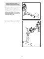
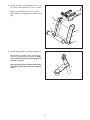
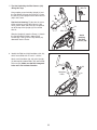
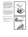
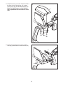
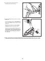
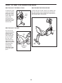
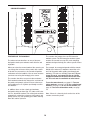
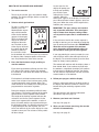
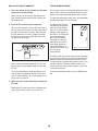
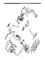
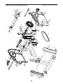
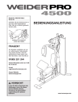
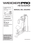
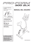
Model No. 831.21752.0
Serial No.
Write the serial number in the
space above for reference.
Serial Number
Decal
• Assembly
• Operation
• Maintenance
• Part List and Drawing
Sears, Roebuck and Co.
Hoffman Estates, IL 60179
CAUTION
Read all precautions and instructions in this manual before using
this equipment. Keep this manual
for future reference.
BIKE EXERCISER
Userʼs Manual
TABLE OF CONTENTS
WARNING DECAL PLACEMENT . . . . . . . . . . . . . . . . . . . . . . . . . . . . . . . . . . . . . . . . . . . . . . . . . . . . . . . . . . . . . .2
IMPORTANT PRECAUTIONS . . . . . . . . . . . . . . . . . . . . . . . . . . . . . . . . . . . . . . . . . . . . . . . . . . . . . . . . . . . . . . . .3
BEFORE YOU BEGIN . . . . . . . . . . . . . . . . . . . . . . . . . . . . . . . . . . . . . . . . . . . . . . . . . . . . . . . . . . . . . . . . . . . . . .4
ASSEMBLY . . . . . . . . . . . . . . . . . . . . . . . . . . . . . . . . . . . . . . . . . . . . . . . . . . . . . . . . . . . . . . . . . . . . . . . . . . . . . . .5
HOW TO USE THE EXERCISE BIKE . . . . . . . . . . . . . . . . . . . . . . . . . . . . . . . . . . . . . . . . . . . . . . . . . . . . . . . . .13
MAINTENANCE AND TROUBLESHOOTING . . . . . . . . . . . . . . . . . . . . . . . . . . . . . . . . . . . . . . . . . . . . . . . . . . .19
EXERCISE GUIDELINES . . . . . . . . . . . . . . . . . . . . . . . . . . . . . . . . . . . . . . . . . . . . . . . . . . . . . . . . . . . . . . . . . . .20
PART LIST . . . . . . . . . . . . . . . . . . . . . . . . . . . . . . . . . . . . . . . . . . . . . . . . . . . . . . . . . . . . . . . . . . . . . . . . . . . . . .21
EXPLODED DRAWING . . . . . . . . . . . . . . . . . . . . . . . . . . . . . . . . . . . . . . . . . . . . . . . . . . . . . . . . . . . . . . . . . . . .22
ORDERING REPLACEMENT PARTS . . . . . . . . . . . . . . . . . . . . . . . . . . . . . . . . . . . . . . . . . . . . . . . . . .Back Cover
90 DAY FULL WARRANTY . . . . . . . . . . . . . . . . . . . . . . . . . . . . . . . . . . . . . . . . . . . . . . . . . . . . . . . . . .Back Cover
WARNING DECAL PLACEMENT
This drawing shows the location(s) of the
warning decal(s). If a decal is missing or
illegible, call 1-888-533-1333 and request a
free replacement decal. Apply the decal in
the location shown. Note: The decal(s) may
not be shown at actual size.
2
IMPORTANT PRECAUTIONS
WARNING:
To reduce the risk of serious injury, read all important precautions and
instructions in this manual and all warnings on your exercise bike before using your exercise bike.
Sears assumes no responsibility for personal injury or property damage sustained by or through
the use of this product.
9. Wear appropriate clothes while exercising;
do not wear loose clothes that could become
caught on the exercise bike. Always wear
athletic shoes for foot protection.
1. Before beginning any exercise program,
consult your physician. This is especially
important for persons over age 35 or persons with pre-existing health problems.
10. The exercise bike should not be used by
persons weighing more than 275 lbs.
(125 kg).
2. Use the exercise bike only as described in
this manual.
3. It is the responsibility of the owner to ensure
that all users of the exercise bike are adequately informed of all precautions.
11. The pulse sensor is not a medical device.
Various factors, including the user's movement, may affect the accuracy of heart rate
readings. The pulse sensor is intended only
as an exercise aid in determining heart rate
trends in general.
4. The exercise bike is intended for home use
only. Do not use the exercise bike in a commercial, rental, or institutional setting.
12. The exercise bike does not have a free
wheel; the pedals will continue to move until
the flywheel stops. Reduce your pedaling
speed in a controlled way.
5. Keep the exercise bike indoors, away from
moisture and dust. Do not put the exercise
bike in a garage or covered patio, or near
water.
13. Always keep your back straight while using
the exercise bike; do not arch your back.
6. Place the exercise bike on a level surface
with at least 2 ft. (0.6 m) of clearance around
the exercise bike. To protect the floor or
carpet from damage, place a mat under the
exercise bike.
14. Over exercising may result in serious injury
or death. If you feel faint or if you experience
pain while exercising, stop immediately and
cool down.
7. Inspect and properly tighten all parts regularly. Replace any worn parts immediately.
8. Keep children under age 12 and pets away
from the exercise bike at all times.
3
BEFORE YOU BEGIN
Thank you for selecting the PROFORM® XP 400 R
exercise bike. Cycling is an effective exercise for
increasing cardiovascular fitness, building endurance,
and toning the body. The XP 400 R exercise bike provides an impressive selection of features designed to
make your workouts at home more effective and
enjoyable.
after reading this manual, please see the back cover
of this manual. To help us assist you, note the product
model number and serial number before contacting
us. The model number and the location of the serial
number decal are shown on the front cover of this
manual.
Before reading further, please familiarize yourself with
the parts that are labeled in the drawing below.
For your benefit, read this manual carefully before
you use the exercise bike. If you have questions
Console
Handlebar
Water Bottle Holder*
Backrest
Seat
Pedal/Strap
Wheel
Pulse Sensor
Adjustment Handle
*Water bottle is not included
4
ASSEMBLY
Assembly requires two persons. Place all parts of the exercise bike in a cleared area and remove the packing
materials. Do not dispose of the packing materials until assembly is completed.
In addition to the included tool(s), assembly requires an adjustable wrench
.
screwdriver
and a Phillips
See the drawings below to identify the small parts needed for assembly. The number in parentheses below each
drawing is the key number of the part, from the PART LIST near the end of this manual. The number following
the key number is the quantity needed for assembly. Note: If a part is not in the hardware kit, check to see if
it has been preassembled. To avoid damaging parts, do not use power tools for assembly. If a part is
missing, call 1-888-533-1333.
M4 x 16mm
Screw (62)–10
M6 x 18mm Patch
Screw (59)–2
M10 x 20mm Patch
Screw (54)–4
M6 Washer
(63)–4
M10 Split
Washer (48)–2
M6 x 38mm Bolt
(55)–4
M6 Locknut
(56)–4
M6 x 42mm Patch
Screw (60)–2
M10 x 36mm
Screw (57)–2
M10 Locknut
(58)–2
1/4" x 38mm Patch
Screw (61)–4
M10 x 64mm Patch
Screw (52)–3
M10 x 80mm Patch Screw (47)–2
5
1.
1
To make assembly easier, read the
information on page 5 before you begin.
With the help of another person, lift the Frame
(1) and place a packing insert (not shown)
under the Frame. Have the other person hold
the Frame to prevent it from moving from side
to side until you complete this step.
3
Attach the Front Stabilizer (3) to the Frame (1)
with two M10 x 80mm Patch Screws (47) and
two M10 Split Washers (48).
1
2. Attach the Rear Stabilizer (2) to the Frame (1)
with three M10 x 64mm Patch Screws (52).
2
52
1
2
6
48
47
3. Identify the Right and Left Stabilizer Covers (12,
13), which are marked with “R” and “L” stickers.
3
Attach each Stabilizer Cover (12, 13) to the
Rear Stabilizer (2) with two M4 x 16mm Screws
(62).
62
62
13
2
62
12
62
4. Identify the Top Shield (14) and the Upright (4).
4
With the help of another person, slide the Top
Shield (14) upward onto the Upright (4). Make
sure that the Top Shield and the Upright are
oriented as shown.
Have the other person continue holding the
Top Shield (14) in place while you complete
step 5.
14
7
4
5. Tip: Avoid pinching the Wire Harness (40)
during this step.
5
Have another person hold the Upright (4) and
the Top Shield (14) near the Frame (1). Locate
the wire tie in the Upright and the Wire Harness
(40) in the Frame.
Wire Tie
54
54
14
See the inset drawing. Tie the wire tie to one
of the connectors on the Wire Harness (40).
Then, pull the other end of the wire tie upward
out of the top of the Upright (4). Discard the
wire tie.
54
4
40
Wire Tie
Slide the Upright (4) onto the Frame (1). Attach
the Upright with four M10 x 20mm Patch
Screws (54). Then, press the Top Shield (14)
downward into the Frame.
6. Identify the Right and Left Handlebars (28, 29),
which are marked with “R” and “L” stickers.
40
1
Avoid
pinching
the Wire
Harness (40)
6
Attach each Handlebar (28, 29) to the Upright
(4) with two M6 x 38mm Bolts (55) and two M6
Locknuts (56). Make sure that the hexagonal
holes are in the indicated location.
4
29
Hexagonal
Holes
8
55
56
28
7. The Console (5) can use four 1.5V D batteries
(not included); alkaline batteries are recommended. IMPORTANT: If the Console has
been exposed to cold temperatures, allow it
to warm to room temperature before inserting batteries. Otherwise, you may damage
the console displays or other electronic
components. Remove the battery cover, insert
the batteries into the battery compartments, and
reattach the battery cover. Make sure to orient
the batteries as shown by the diagram
inside the battery compartments.
7
Battery
Cover
Batteries
5
Note: The battery cover may be attached with
screws.
To purchase an optional power adapter, call
the telephone number on the cover of this
manual. To avoid damaging the console, use
only a manufacturer-supplied power adapter.
Plug one end of the power adapter into the
receptacle on the console; plug the other end
into an outlet installed in accordance with all
local codes and ordinances.
8. Tip: Avoid pinching the wires during this
step.
8
While another person holds the Console (5)
near the Upright (4), connect the console wires
to the Wire Harness (40). Insert the excess wire
downward into the Upright.
Attach the Console (5) to the Upright (4) with
four M4 x 16mm Screws (62).
5
Console
Wires
9
4
40
Avoid pinching
the wires
62
9. Tip: Avoid pinching the Pulse Wire (38)
during this step.
Orient the Pulse Bar (7) as shown. Attach the
Pulse Bar to the Seat Carriage (6) with two M10
x 36mm Screws (57) and two M10 Locknuts
(58). Do not tighten the Screws yet.
9
Avoid pinching the
Pulse Wire (38)
7
38
58
6
57
57
10. Tip: Avoid pinching the Pulse Wire (not
shown) during this step.
Attach the Backrest (8) to the Seat Carriage (6)
with two M6 x 18mm Patch Screws (59) and
two M6 x 42mm Patch Screws (60).
10
59
8
See step 9. Tighten the M10 x 36mm Screws
(57).
6
Avoid pinching the
Pulse Wire (not shown)
10
60
11. Orient the Seat (9) as shown. Attach the Seat to
the Seat Carriage (6) with four 1/4" x 38mm
Patch Screws (61) and four M6 Washers (63).
Note: The Patch Screws and the Washers
may be preattached to the underside of the
Seat.
11
9
6
63
61
12. Attach the Pulse Bar Cover (15) to the Seat
Carriage (6) with two M4 x 16mm Screws (62).
61
12
15
62
11
6
13. Plug the Pulse Wire (38) into the Pulse
Receptacle (39) in the Frame (1).
13
38
39
14. Identify the Right Pedal (44), which is marked
with an “R.”
Using an adjustable wrench, firmly tighten the
Right Pedal clockwise into the right side of the
Crank (17).
1
14
Tighten the Left Pedal (not shown) counterclockwise into the left side of the Crank.
Adjust the strap on the Right Pedal (44) to the
desired position, and press the ends of the
straps onto the tabs on the Right Pedal. Adjust
the strap on the Left Pedal (not shown) in
the same way.
17
Strap
44
Tab
15. Make sure that all parts are properly tightened before you use the exercise bike. Note: After assembly
is completed, some extra parts may be left over. Place a mat beneath the exercise bike to protect the floor.
12
HOW TO USE THE EXERCISE BIKE
HOW TO ADJUST THE PEDAL STRAPS
To adjust the pedal
straps, first pull the
ends of the straps
off the tabs on the
pedals. Adjust the
straps to the
desired position,
and then press the
ends of the straps
onto the tabs.
HOW TO MOVE THE EXERCISE BIKE
To move the exercise bike, lift the rear stabilizer until
the exercise bike can be moved on the front wheels.
Carefully move the exercise bike to the desired location and then lower it to the floor.
Pedal
Strap
Tab
HOW TO ADJUST THE SEAT
The seat can be
adjusted forward or
backward to the
position that is the
most comfortable
for you. To adjust
the seat, push
downward on the
adjustment handle,
slide the seat to the
desired position,
and then pull
upward on the
adjustment handle
to lock the seat in
place.
Wheel
Seat
Lift
Here
Adjustment
Handle
13
CONSOLE DIAGRAM
FEATURES OF THE CONSOLE
The console also features the new iFit interactive
workout system. The iFit interactive workout system
enables the console to accept iFit cards containing
workouts designed to help you achieve specific fitness
goals.
The advanced console offers an array of features
designed to make your workouts more effective and
enjoyable.
When you select the manual mode of the console, you
can change the resistance of the pedals with a touch
of the dial. As you exercise, the console will provide
continuous exercise feedback. You can even measure
your heart rate using the handgrip pulse sensor.
For example, lose unwanted pounds with the 8-week
Weight Loss workout. iFit workouts control the resistance of the pedals while guiding you through your
workouts. iFit cards are available separately. To purchase iFit cards, go to www.iFit.com or call the
telephone number on the front cover of this manual. iFit cards are also available at select stores.
The console also offers ten preset trainer workouts.
Each workout automatically changes the resistance of
the pedals and prompts you to increase or decrease
your pedaling pace as it guides you through an effective workout.
To use the manual mode, see page 15. To use a
trainer workout, see page 16. To use a calorie goal
workout, see page 17. To use an iFit workout, see
page 18. To use the information mode, see page
18.
In addition, there are four calorie goal workouts
designed to help you burn 150, 175, 200, or 225 calories in a 30 minute workout. The calorie goal workouts
automatically control the resistance of the pedals and
prompt you to vary your pedaling pace while counting
down the calories you burn.
Note: If there is a sheet of plastic on the face of the
console, remove the plastic.
14
HOW TO USE THE MANUAL MODE
The third section of
the display will show
the approximate number of calories you
have burned and the
resistance level of the
pedals. The display will change modes every few
seconds. The display will also show your heart
rate when you use the handgrip pulse sensor (see
step 5 below).
1. Turn on the console.
To turn on the console, press any button or begin
pedaling. The display will light and the console will
be ready for use.
2. Select the manual mode.
Each time you turn on
the console, the
manual mode will be
selected. If you have
selected a workout,
reselect the manual
mode by pressing the
Workout button
repeatedly until zeroes
appear in the display.
The last section of
the display will show a
track representing 1/4
mile (400 meters). As
you exercise, indicators will appear in
succession around the track until the entire track
appears. The track will then disappear and the
indicators will again begin to appear in succession
The console can show speed and distance in
either miles or kilometers. The letters MPH or
Km/H will appear in the display to indicate which
unit of measurement is selected. To change the
unit of measurement, see THE INFORMATION
MODE on page 18.
3. Begin pedaling and change the resistance of
the pedals as desired.
As you pedal, change
the resistance of the
pedals by turning the
Resistance dial. To
increase the resistance, turn the
Resistance dial clockwise; to decrease the resistance, turn the Resistance dial counterclockwise.
Note: After you change the resistance, it will take a
moment for the pedals to reach the selected resistance level.
5. Measure your heart rate if desired.
If there are sheets
of plastic on the
metal contacts on
Contacts
the handgrip pulse
sensor, remove the
plastic. Next, hold
the handgrip pulse
sensor with your
palms resting on the
metal contacts.
Avoid moving your
hands or gripping
the contacts too
tightly. When your pulse is detected, a heartshaped symbol will flash in the display each time
your heart beats and then your heart rate will be
shown. For the most accurate heart rate reading,
hold the contacts for at least 15 seconds.
4. Follow your progress with the display.
The upper section of
the display will show
the elapsed time and
the distance, in miles
or kilometers, that you
have pedaled. The display will change modes every few seconds. Note:
When you select a workout, the display will show
the time remaining in the workout instead of the
elapsed time.
6. When you are finished exercising, the console
will turn off automatically.
The second section
of the display will
show your pedaling
pace in miles or kilometers per hour.
If the pedals do not move for a few seconds, the
time will begin to flash in the display and the console will pause. If the pedals do not move for a
few minutes and no buttons are pressed, the console will turn off and the display will be reset.
15
HOW TO USE A TRAINER WORKOUT
As you exercise, the
display will prompt you
to keep your pedaling
pace near the pace
setting for the current
segment. When the
word “faster” appears in the display, increase your
pace. When the word “slower” appears, decrease
your pace. When the center of the target flashes,
maintain your current pace.
1. Turn on the console.
To turn on the console, press any button or begin
pedaling. The display will light and the console will
be ready for use.
2. Select a trainer workout.
To select a trainer
workout, press the
Workout button repeatedly until the number
of the desired workout
appears in the display.
The first section of the
display will show the
duration of the workout. A profile of the
resistance levels for
the workout will scroll
across the last section
of the display. Note:
Complete profiles of the workouts are printed on
the sides of the console.
IMPORTANT: The pace settings are intended
only to provide motivation. Your actual pace
may be slower than the pace settings. Make
sure to pedal at a pace that is comfortable for
you.
If the resistance level for the current segment is
too high or too low, you can manually override the
level by turning the Resistance dial. IMPORTANT:
When the current segment of the workout
ends, the pedals will automatically adjust to
the resistance setting for the next segment.
If you stop pedaling for several seconds, the console will pause and the time will begin to flash in
the display. To restart the workout, press the Start
button or simply resume pedaling.
3. Press the Start button or begin pedaling to
start the workout.
The workout will continue until the display shows a
time of 0:00. Note: If you continue to pedal after
the workout is completed, the display will continue
to show exercise feedback; however, the display
will not show the elapsed time until you select the
manual mode or a new workout.
Each workout is divided into 30 one-minute segments. One resistance level and one pace setting
are programmed for each segment. Note: The
same resistance level and/or pace setting may be
programmed for consecutive segments.
4. Follow your progress with the display.
During the workout, the workout profile will show
your progress. The flashing segment of the profile
represents the current segment of the workout.
The height of the flashing segment indicates the
resistance level for the current segment. At the
end of each segment of the workout, a series of
tones will sound and the next segment of the profile will begin to flash. If a different resistance level
is programmed for the next segment, the resistance level will flash in the center display for a few
seconds to alert you. The resistance of the pedals
will then change.
See step 4 on page 15.
5. Measure your heart rate if desired.
See step 5 on page 15.
6. When you are finished exercising, the console
will turn off automatically.
See step 6 on page 15.
16
HOW TO USE A CALORIE GOAL WORKOUT
As you exercise, the
display will prompt you
to keep your pedaling
pace near the pace
setting for the current
segment. When the
word “faster” appears in the display, increase your
pace. When the word “slower” appears, decrease
your pace. When the center of the target flashes,
maintain your current pace.
1. Turn on the console.
To turn on the console, press any button or begin
pedaling. The display will light and the console will
be ready for use.
2. Select a calorie goal workout.
To select a calorie goal
workout, press the
Workout button repeatedly until the number
of the desired workout
appears in the display.
The first section of the
display will show the
duration of the workout. The third section
of the display will show
the calorie goal for the
workout. A profile of
the resistance levels
for the workout will scroll across the last section of
the display. Note: Complete profiles of the workouts are printed on the sides of the console.
IMPORTANT: The pace settings are intended
only to provide motivation. Your actual pace
may be slower than the pace settings. Make
sure to pedal at a pace that is comfortable for
you.
If the resistance level for the current segment is
too high or too low, you can manually override the
level by turning the Resistance dial. IMPORTANT:
When the current segment of the workout
ends, the pedals will automatically adjust to
the resistance setting for the next segment.
If you stop pedaling for several seconds, the console will pause and the time will begin to flash in
the display. To restart the workout, press the Start
button or simply resume pedaling.
3. Press the Start button or begin pedaling to
start the workout.
The workout will continue until the display shows a
time of 0:00. Note: If you continue to pedal after
the workout is completed, the display will continue
to show exercise feedback; however, the display
will not show the elapsed time until you select the
manual mode or a new workout.
Each calorie goal workout will help you burn 150,
175, 200, or 225 calories. During each workout,
the console will count down the number of calories
to be burned.
4. Follow your progress with the display.
Each workout is divided into 30 one-minute segments. One resistance level and one pace setting
are programmed for each segment. Note: The
same resistance level and/or pace setting may be
programmed for consecutive segments.
During a calorie goal workout, the third section of
the display will show the number of calories to be
burned during the remaining segments of the
workout.
During the workout, the workout profile will show
your progress. The flashing segment of the profile
represents the current segment of the workout.
The height of the flashing segment indicates the
resistance level for the current segment. At the
end of each segment of the workout, a series of
tones will sound and the next segment of the profile will begin to flash. If a different resistance level
is programmed for the next segment, the resistance level will flash in the center display for a few
seconds to alert you. The resistance of the pedals
will then change.
The other displays will show the information
described in step 4 on page 15.
5. Measure your heart rate if desired.
See step 5 on page 15.
6. When you are finished exercising, the console
will turn off automatically.
See step 6 on page 15.
17
HOW TO USE AN IFIT WORKOUT
THE INFORMATION MODE
1. Press any button on the console or begin pedaling to turn on the console.
The console features an information mode that allows
you to select a unit of measurement for the console
and to view usage information for the exercise bike.
When you turn on the console, the display will
light. A tone will then sound and the console will
be ready for use.
To select the information mode, press and hold down
the Workout button for a few seconds.
2. Insert an iFit card and select a workout.
The display will show the
selected unit of measurement. An “E” for English
miles or an “M” for metric
kilometers will appear in
the display. To change the
unit of measurement,
press the Start button
repeatedly to select the
desired unit of measurement. Note: When you
replace the batteries, it
may be necessary to reselect the unit of
measurement.
To use an iFit workout, insert an iFit card into the
iFit slot; make sure that the iFit card is oriented so
the metal contacts are face-down and are facing
the slot. When the iFit card is properly inserted,
the indicator next to the slot will light and words
will appear in the display.
iFit Slot
iFit Card
The display will also show the total distance pedaled
since the exercise bike was purchased and the total
number of hours the exercise bike has been used.
The total distance pedaled will appear in the first section of the display. The total number of hours the
exercise bike has been used will appear in the third
section of the display.
Next, select the desired workout on the iFit card
by pressing the up and down buttons next to the
iFit slot.
Press the Start button or begin pedaling to start
your workout. iFit workouts function in the same
way as trainer workouts. To use the workout, see
steps 3 to 5 on page 16.
To exit the information mode, press the Workout button.
3. When you are finished exercising, remove the
iFit card.
Remove the iFit card when you are finished exercising. Store the iFit card in a secure place.
18
MAINTENANCE AND TROUBLESHOOTING
Inspect and tighten all parts of the exercise bike regularly. To clean the exercise bike, use a damp cloth and
a small amount of mild detergent; never use abrasives or solvents to clean the exercise bike. To
avoid damaging the console, keep liquid away
from the console.
Slide the Reed Switch (24) slightly closer to or away
from the Magnet (50), and then retighten the M4 x
16mm Screw (62). Turn the Crank (17) for a moment.
Repeat these actions until the console displays correct
feedback. When the reed switch is correctly adjusted,
reattach the left shield and the left pedal.
CONSOLE TROUBLESHOOTING
HOW TO ADJUST THE BELT
If the console display becomes dim, replace all the
batteries at the same time; most console problems are
the result of low batteries. See assembly step 7 on
page 9 for replacement instructions.
If you can feel the pedals slip while you are pedaling,
even when the resistance is at the highest level, the
belt may need to be adjusted.
If the handgrip pulse sensor does not function properly, see step 5 on page 15.
To adjust the belt, you must first remove the right
pedal and the right shield.
HOW TO ADJUST THE REED SWITCH
Using an adjustable wrench, turn the right pedal counterclockwise and remove it. Next, remove the screws
from the left and right shields. Then, gently remove
the right shield.
If the console does not display correct feedback, the
reed switch should be adjusted. To adjust the reed
switch, you must first remove the left pedal and the
left shields.
To tighten the belt, first loosen the M8 x 22mm Flat
Head Screw (67). Next, tighten the M10 x 90mm
Button Screw (69) until the Belt (18) is tight. Then,
retighten the M8 x 22mm Flat Head Screw (67).
Reattach the right shield and the right pedal.
Using an adjustable wrench, turn the left pedal clockwise and remove it. Next, remove the screws from the
left and right shields. Then, gently remove the left
shield.
Locate the Reed Switch (24). Turn the Crank (17) until
a Magnet (50) is aligned with the Reed Switch. Next,
loosen, but do not remove, the indicated M4 x 16mm
Screw (62).
17
67
50 24 62
18
69
19
EXERCISE GUIDELINES
WARNING:
Burning Fat—To burn fat effectively, you must exercise at a low intensity level for a sustained period of
time. During the first few minutes of exercise, your
body uses carbohydrate calories for energy. Only after
the first few minutes of exercise does your body begin
to use stored fat calories for energy. If your goal is to
burn fat, adjust the intensity of your exercise until your
heart rate is near the lowest number in your training
zone. For maximum fat burning, exercise with your
heart rate near the middle number in your training
zone.
Before beginning this
or any exercise program, consult your physician. This is especially important for persons
over age 35 or persons with pre-existing
health problems.
The pulse sensor is not a medical device.
Various factors may affect the accuracy of
heart rate readings. The pulse sensor is
intended only as an exercise aid in determining heart rate trends in general.
Aerobic Exercise—If your goal is to strengthen your
cardiovascular system, you must perform aerobic
exercise, which is activity that requires large amounts
of oxygen for prolonged periods of time. For aerobic
exercise, adjust the intensity of your exercise until
your heart rate is near the highest number in your
training zone.
These guidelines will help you to plan your exercise
program. For detailed exercise information, obtain a
reputable book or consult your physician. Remember,
proper nutrition and adequate rest are essential for
successful results.
WORKOUT GUIDELINES
EXERCISE INTENSITY
Warming Up—Start with 5 to 10 minutes of stretching
and light exercise. A warm-up increases your body
temperature, heart rate, and circulation in preparation
for exercise.
Whether your goal is to burn fat or to strengthen your
cardiovascular system, exercising at the proper intensity is the key to achieving results. You can use your
heart rate as a guide to find the proper intensity level.
The chart below shows recommended heart rates for
fat burning and aerobic exercise.
Training Zone Exercise—Exercise for 20 to 30 minutes with your heart rate in your training zone. (During
the first few weeks of your exercise program, do not
keep your heart rate in your training zone for longer
than 20 minutes.) Breathe regularly and deeply as you
exercise–never hold your breath.
Cooling Down—Finish with 5 to 10 minutes of
stretching. Stretching increases the flexibility of your
muscles and helps to prevent post-exercise problems.
EXERCISE FREQUENCY
To find the proper intensity level, find your age at the
bottom of the chart (ages are rounded off to the nearest ten years). The three numbers listed above your
age define your “training zone.” The lowest number is
the heart rate for fat burning, the middle number is the
heart rate for maximum fat burning, and the highest
number is the heart rate for aerobic exercise.
To maintain or improve your condition, complete three
workouts each week, with at least one day of rest
between workouts. After a few months of regular exercise, you may complete up to five workouts each
week, if desired. Remember, the key to success is to
make exercise a regular and enjoyable part of your
everyday life.
20
PART LIST
Key No. Qty.
1
2
3
4
5
6
7
8
9
10
11
12
13
14
15
16
17
18
19
20
21
22
23
24
25
26
27
28
29
30
31
32
33
34
35
36
37
38
39
40
1
1
1
1
1
1
1
1
1
1
1
1
1
1
1
1
1
1
1
1
1
1
1
1
1
1
1
1
1
2
2
2
2
4
2
4
4
1
1
1
Description
Key No. Qty.
Frame
Rear Stabilizer
Front Stabilizer
Upright
Console
Seat Carriage
Pulse Bar
Backrest
Seat
Right Shield
Left Shield
Right Stabilizer Cover
Left Stabilizer Cover
Top Shield
Pulse Bar Cover
Eddy Mechanism
Pulley/Crank
Belt
Idler
Resistance Motor
Crank Bearing Assembly
Flywheel Axle
Clamp
Reed Switch Wire
Adjustment Handle
Seat Lock
Seat Lock Bracket
Right Handlebar
Left Handlebar
Handlebar Cap
Seat Carriage Cap
Upper Roller
Lower Roller
Roller Axle
Pulse Grip
Pulse Sensor
Pulse Contact
Pulse Wire
Pulse Receptacle/Wire
Wire Harness
41
42
43
44
45
46
47
48
49
50
51
52
53
54
55
56
57
58
59
60
61
62
63
64
65
66
67
68
69
70
71
72
73
*
*
*
*
*
*
2
2
2
1
1
2
2
2
1
2
1
3
4
4
4
4
2
3
2
2
4
24
14
8
1
2
1
1
1
2
1
10
1
–
–
–
–
–
–
Model No. 831.21752.0 R1110A
Description
Wheel
Stabilizer Cap
Bumper
Right Pedal/Strap
Left Pedal/Strap
M10 x 41mm Shoulder Screw
M10 x 80mm Patch Screw
M10 Split Washer
M4 x 16mm Bright Screw
Magnet
Resistance Cable
M10 x 64mm Patch Screw
M3.8 x 20mm Screw
M10 x 20mm Patch Screw
M6 x 38mm Bolt
M6 Locknut
M10 x 36mm Screw
M10 Locknut
M6 x 18mm Patch Screw
M6 x 42mm Patch Screw
1/4" x 38mm Patch Screw
M4 x 16mm Screw
M6 Washer
1/4" x 16mm Button Screw
M10 Washer
M5 x 14mm Screw
M8 x 22mm Flat Head Screw
M8 Locknut
M10 x 90mm Button Screw
1/4" x 14mm Screw
M8 Washer
M6 Split Washer
M4 x 22mm Screw
Assembly Tool
15 1/2" Zip Tie
8" Zip Tie
Panel Fastener
Grommet
Userʼs Manual
Note: Specifications are subject to change without notice. For information about ordering replacement parts, see
the back cover of this manual. If a part is missing, call 1-888-533-1333. *These parts are not illustrated.
21
22
72
64
72
62
57
64
57
7
35
36
37
63
63
53
64
58
63
61
33
32
34
34
64
6
58
63
63
63
9
72
72
64
64
31
63
53
72
27
63
35
37
36
70
72
26
8
38
29
60
59
25
40
59 60
30
56
15
5
39
55
54
4
14
54
56
54
30
62
54
28
55
EXPLODED DRAWING A
Model No. 831.21752.0 R1110A
62
23
42
62
13
62
62
45
52
62
43
11
73
42
2
62
45
51
16
58 65
62
12
62
62
43
66
22
49 20
21
1
62
18
68 71
69
46
67
23
17
19
50
21
24
41
50
62
3
62
62
41
48
62
10
46
44
44
47
EXPLODED DRAWING B
Model No. 831.21752.0 R1110A
Get it fixed, at your home or ours!
Your Home
For repair—in your home—of all major brand appliances, lawn and garden equipment,
or heating and cooling systems, no matter who made it, no matter who sold it!
For the replacement parts, accessories, and user’s manuals that you need to do-it-yourself.
For Sears professional installation of home appliances
and items like garage door openers and water heaters.
1-800-4-MY-HOME® (1-800-469-4663)
Call anytime, day or night (U.S.A. and Canada)
www.sears.com
www.sears.ca
Our Home
For repair of carry-in items like vacuums, lawn equipment,
and electronics, call or go on-line for the location of your nearest
Sears Parts & Repair Center.
1-800-488-1222 Call anytime, day or night (U.S.A. only)
www.sears.com
To purchase a protection agreement (U.S.A.)
or maintenance agreement (Canada) on a product serviced by Sears:
1-800-827-6655 (U.S.A.)
1-800-361-6665 (Canada)
Para pedir servicio de reparación a domicilio, y para ordenar piezas:
1-888-SU-HOGAR® (1-888-784-6427)
® Registered Trademark / TM Trademark / SM Service Mark of Sears Brands, LLC
® Marca Registrada / TM Marca de Fábrica / SM Marca de Servicio de Sears Brands, LLC
90 DAY FULL WARRANTY
If this Sears bike exerciser fails due to a defect in material or workmanship within 90 days of the date of
purchase, call 1-800-4-MY-HOME® (1-800-469-4663) to arrange for free repair (or replacement if repair
proves impossible). The frame is warranted for a period of 7 years from the date of purchase.
This warranty does not apply when the bike exerciser is used commercially or for rental purposes.
This warranty gives you specific legal rights, and you may also have other rights which vary from state
to state.
Sears, Roebuck and Co., Hoffman Estates, IL 60179
Part No. 264264 R1110A
Printed in China © 2010 ICON IP, Inc.