1
North America
METALSHARK®2BD
English Operator’sManual
Tectronix Systems Inc., 9 - 18812 96 Ave, Surrey BC, Canada, V4N 3R1
PH: +1 604-607-6028, FAX +1 604-607-6026 www.metal-shark.com
METAL SHARK® 2 BD Operator’s Manual
2
Software Version 1.10a and higher
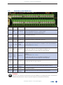
Index
Index
3.
3.1.
3.2.
3.3.
3.3.1.
3.3.2.
3.3.3.
3.3.4.
Safety Messages.................................................................................................. 7
Safety Symbols and Definitions...............................................................................................7
General Safety Instructions......................................................................................................7
Safety Instructions for the Metal Detector..............................................................................9
Installation Instructions........................................................................................................ 9
Connecting Instructions...................................................................................................... 9
Instructions about Operation............................................................................................. 9
Protection against Interference......................................................................................... 9
4.
Getting Started....................................................................................................11
5.
Introduction........................................................................................................ 13
5.1.
5.1.1.
5.1.2.
5.1.3.
5.1.4.
5.2.
5.2.1.
5.2.2.
5.2.3.
5.2.4.
5.2.5.
6.
6.1.
6.2.
6.3.
6.4.
7.
7.1.
7.2.
8.
8.1.
8.2.
8.3.
8.4.
8.5.
8.6.
8.7.
8.8.
8.9.
9.
9.1.
9.2.
9.3.
General Information...............................................................................................................13
Information about this Manual..........................................................................................13
Content of this Manual.......................................................................................................13
Target Group for this Manual.............................................................................................13
Typographic Conventions..................................................................................................14
Scope of Application and Qualification..............................................................................15
Normal Use...........................................................................................................................15
Misuse...................................................................................................................................15
Owner’s Obligation to Exercise Due Care.......................................................................15
Requirements for Operating Staff.....................................................................................16
Requirements for Service and Maintenance Staff.........................................................16
Technical Description........................................................................................ 17
Method of Operation.............................................................................................................. 17
Operating Limits...................................................................................................................... 17
Technical Data........................................................................................................................18
Metal Detector METAL SHARK® 2 BD.....................................................................................19
Transport.............................................................................................................. 21
Safety & Protection Instructions.............................................................................................21
Lifting........................................................................................................................................22
Mechanical Installation..................................................................................... 23
Metal-Free Zone......................................................................................................................23
Minimum Distance Between Motor and Sensor Head........................................................24
Gap Between Sensor Head and Product.............................................................................24
Vibrations.................................................................................................................................24
Feed of Belt Through Sensor Head........................................................................................25
Mounting on Conveyor / Frame............................................................................................25
Keep Conveyor Belt Clean....................................................................................................26
Welding of Transversal Struts and Contact Points................................................................26
Isolation of Drums and Shafts................................................................................................27
Electrical Installation......................................................................................... 29
Terminals of Power Supply Board..........................................................................................30
Relay K1, K2 - Function...........................................................................................................30
Terminals on the Mainboard..................................................................................................31
Software Version 1.10a and higher
3
METAL SHARK® 2 BD Operator’s Manual
9.4.
9.4.1.
9.4.2.
Wiring Diagram Examples......................................................................................................32
Belt Controls STR1 and STL1................................................................................................ 32
Belt Controls STR2 and STL2............................................................................................... 33
10. Control Panel and Main Screens...................................................................... 35
10.1.
The Control Panel....................................................................................................................35
10.2.
The Main Screens....................................................................................................................36
10.2.1.
The Bar Graph's Screen Elements.....................................................................................37
10.2.2.
The 2D Plot's Screen Elements.......................................................................................... 38
10.2.3.
The Scope's Screen Elements........................................................................................... 39
11. Initial Parameter Setup (all types, except BIG pba)....................................... 41
12. Daily Operation Overview................................................................................. 43
11. Daily Operation.................................................................................................. 45
11.1.
11.2.
11.3.
11.4.
11.4.1.
11.4.2.
PRODUCT – Select & Edit Existing Products.........................................................................45
TEST – Check Metal Detector's Performance.....................................................................46
TEACH – Add New Product....................................................................................................47
OPTIMIZE – Improve Stability & Sensitivity...........................................................................51
Optimize with the Histogram.............................................................................................51
Optimize with the 2D Plot.................................................................................................. 53
12. MENU – Daily Operation Setup......................................................................... 57
12.1.
12.1.1.
12.1.2.
12.1.3.
12.1.4.
12.1.5.
12.1.6.
12.1.7.
12.1.8.
12.1.9.
12.1.10.
12.1.11.
12.1.12.
12.2.
12.3.
12.4.
REPORT MENU........................................................................................................................57
IFS/HACCP REPORT............................................................................................................. 58
METAL REPORT..................................................................................................................... 59
EVENT REPORT..................................................................................................................... 59
METAL COUNTER................................................................................................................. 59
TOTAL COUNTER.................................................................................................................. 59
PRINT.................................................................................................................................... 60
INTERFACE............................................................................................................................ 60
BAUDRATE RS232................................................................................................................. 60
SHARKNET UNIT #................................................................................................................. 60
MAIN SCREEN...................................................................................................................... 60
HISTOGRAM LIMIT %............................................................................................................ 60
INFO SOFTWARE.................................................................................................................. 60
TEST MENU..............................................................................................................................61
PASSWORD (MENU)................................................................................................................62
PRODUCT MENU......................................................................................................................63
13. MENU – General Settings.................................................................................. 65
13.1.
13.1.1.
13.1.2.
13.1.3.
PRODUCT MENU.....................................................................................................................65
REJECT MENU........................................................................................................... 65
TEACH SETUP............................................................................................................ 67
ADVANCED (MENU)........................................................................................................... 68
13.2.
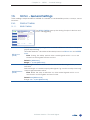
SYSTEM MENU................................................................................................... 71
13.2.1.
DATE/TIME MENU...................................................................................................... 71
13.2.2.
AUTOSPEED MENU.................................................................................................... 72
13.2.3.
CIP MENU................................................................................................................. 73
13.2.4.
BRC MENU............................................................................................................................74
13.2.5.
IN/OUT MENU............................................................................................................74
13.2.6.
FILTER MENU............................................................................................................. 78
4
Software Version 1.10a and higher
Index
13.3.
FACTORY MENU................................................................................................. 80
14. Trouble Shooting................................................................................................. 81
14.1.
Error Messages........................................................................................................................81
14.2.
Reset to Default Values..........................................................................................................82
14.2.1.
Passwords and Language................................................................................................ 82
14.2.2.
Factory Settings.................................................................................................................. 82
14.3.
Problem Solving......................................................................................................................83
14.3.1.
Problem: Still Considerable Metal Alarms After TEACH................................................. 83
14.3.2.
Problem: Still Few Metal Alarms After TEACH.................................................................. 83
14.3.3.
Problem: TEACH ends After Short Period of Time........................................................... 83
14.3.4.
Problem: Poor Metal Sensitivity After TEACH.................................................................. 83
15. Maintenance and Regular Inspections........................................................... 85
15.1.
15.2.
15.3.
Maintenance...........................................................................................................................85
Regular Inspections................................................................................................................85
Notes........................................................................................................................................85
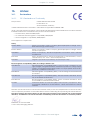
16. Annex.................................................................................................................. 87
16.1.
16.1.1.
16.1.2.
Declarations............................................................................................................................87
CE - Declaration of Conformity.........................................................................................87
Declaration of Manufacturer........................................................................................... 88
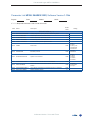
Parameter List METAL SHARK® 2 BD/ Software Version 1.10a.................................... 89
Software Version 1.10a and higher
5
METAL SHARK® 2 BD Operator’s Manual
6
Software Version 1.10a and higher
Chapter 3 – Safety Messages
3.
Safety Messages
3.1.
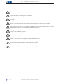
Safety Symbols and Definitions
In this manual we use the following safety symbols. These symbols are supposed to draw the
readers attention especially to the text next to the safety symbol.
General Danger!
This Symbol indicates that there is a potential danger for life and health.
Danger due to High Voltage!
This symbol indicates that there is a potential danger for health and life due to high
voltage. Only qualified electricians are allowed to carry out tasks that are marked
with this symbol.
Danger due to Moving Parts!
This symbol indicates that exposed moving parts may injure your fingers or hand.
Caution!
This symbol indicates that there is a potential danger for machinery, material or
the environment.
3.2.
General Safety Instructions
Danger!
Before working with the metal detector read these safety instructions thoroughly.
Never put the metal detector into operation without the safety devices provided by
the manufacturer. Only specially trained maintenance staff is allowed to operate the
equipment without the safety devices.
Shut down the machine immediately if the safety devices are not operating properly
or if there are other apparent defects which pose a danger. Any defects must be eliminated or reported immediately.
Always observe any warning signs attached to the machine. They help prevent dangerous situations. The removing of these warning signs is strictly prohibited.
Never put the metal detector into operation
yy if you have not received complete initial training from the owner,
yy if you have not fully read the operating instructions or
yy if you have not fully understood the operating instructions.
Not operating the machine correctly may result in severe injury or damage.
Entering the area of the equipment is strictly prohibited for unauthorised persons. An
unauthorised person is a person who has not been instructed to work on the metal
detector.
Wear closely fitting working clothes which cannot get caught in rotating parts (e.g.
conveyor belt).
Software Version 1.10a and higher
7
METAL SHARK® 2 Operator’s Manual
Keep the floor at your place of work clean. Remove oil and obstructions immediately.
Open flames and smoking are not allowed.
Motor control equipment and electronic controllers are connected to hazardous line
voltages.
Never touch any live parts. Electric shocks may lead to severe injury or death.
Disconnect power before checking controllers or performing maintenance, be sure
equipment is properly connected to Protective Earth (PE).
During servicing or maintenance work always wear insulated safety shoes with thick
crepe soles and safety glasses.
Report any damaged cables to the maintenance staff immediately.
Keep all access doors to the electrical equipment locked.
Do NOT operate the machine without guards in place.
Do NOT touch parts marked with this symbol during machine in operation.
8
Software Version 1.10a and higher
Chapter 3 – Safety Messages
3.3.
Safety Instructions for the Metal Detector
Attention!
Smooth and safe running of METAL SHARK® BD Metal Detectors is only possible if the following measures have been taken.
3.3.1.
Installation Instructions
Always attach an earth clamp for welding equipment directly next to the weld.
Never allow the welding current to flow through the housing of the metal detector. This would
damage the metal detector beyond repair.
3.3.2.
Connecting Instructions
yy Make sure that the mains voltage is the same as that required for the equipment.
yy The detector must be fitted and connected up by trained staff only.
yy Observe general installation regulations for setting up and operating electrical equipment
(VDE 0100).
yy Consequently, never perform any work on the metal detector when it is switched on.
yy Take precautions to protect human life and the machine in accordance with the local
conditions and regulations.
yy The Metal Detector METAL SHARK® 2 BD series is designed for permanent, steady-state
installation.
yy Never connect or disconnect control cables or coaxial cables whilst the metal detector is
switched on.
yy Never connect mains cables, control cables or coaxial cables incorrectly.
yy Observe maximum operating voltage and the current-carrying capacity of the output
contacts.
yy Use screened/twisted-wire mains and control cables.
yy Never lay the mains cable and control cable together in a single cable run.
yy Make sure the metal detector is properly earthen (protective earth - PE).
3.3.3.
Instructions about Operation
To prevent Metal Detector METAL SHARK® series from ageing prematurely or being damaged
beyond repair, please observe the following instructions:
yy The metal detector should always remain switched on. This will maximise the service life of
the electronic circuitry.
yy Only operate the metal detector under suitable conditions (refer to chapter “3.2.1. Normal
Use”).
3.3.4.
Protection against Interference
The mains input of the metal detector is protected against interference.
A high level of operational reliability and additional protection against malfunctions is achieved
by the following measures:
yy Use of mains filters if the mains voltage is affected by the switching-on of heavy-load appliances (compensation systems, welding equipment, HF furnaces, solenoid valves, etc.).
yy Providing suppresser circuits for inductance appliances (solenoid valves, contactors, electromagnets) using RC elements (Resistor/Capacitor elements) in order to absorb the energy
being released by switching off.
Software Version 1.10a and higher
9
METAL SHARK® 2 Operator’s Manual
10
Software Version 1.10a and higher
Chapter 4 – Getting Started
4.
GettingStarted
Here we provide an overview of the actions you have to take before starting to work with the
metal detector METAL SHARK® 2 BD.
1.
Read the safety instructions.
2.
Become familiar with the metal detector.
3.
Move the metal detector to the location where you want to install it.
Note:Formoreinformationreadchapter“1.SafetyMessages”.
Note:Formoreinformationreadchapter“4.TechnicalDescription”.
Note:Formoreinformationreadchapter“5.Transport”
Install the metal detector mechanically.
4.
Note: For more information read chapter “6. Mechanical
Installation”
Check the metal detector’s electrical installation and connect the mains
power.
5.
6.
7.
8.
9.
Note:Formoreinformationreadchapter“7.ElectricalInstallation”
OK
MOZZARELLA
PRODUCT
5
Become familiar with the control panel and the main screens.
TEST
TEACH
OPTIMIZE
MENU
Total
Metal
7
0
0%
25 mV
166.50°
SETUP
Note:Formoreinformationreadchapter“8.ControlPanelandMain
Screens”
Set up parameters for initial operation.
Note:Formoreinformationreadchapter“9.InitialParameterSetup”
Teach products, optimize stability and sensitivity, check the performance
and then start your normal production.
TEACH
Note: For more information read chapter “10. Daily Operation
Overview”, “11. Daily Operation” and “12. MENU - Daily Operation
Setup”
If necessary change further settings of the METAL SHARK® 2.
MENU
Note: For more information read chapter “13. MENU - General
Settings”
Software Version 1.10a and higher
11
METAL SHARK® 2 Operator’s Manual
12
Software Version 1.10a and higher
Chapter 5 – Introduction
5.
Introduction
5.1.
General Information
5.1.1.
Information about this Manual
Validity:
Manufacturer:
Print date of this manual:
5.1.2.
Metal detector type METAL SHARK® 2 BD BD
CASSEL Messtechnik GmbH
In der Dehne 10
37127 Dransfeld
Germany
27. October 2009
Content of this Manual
This manual contains all general information that is necessary for setting up and running METAL
SHARK® 2 BD Metal Detectors.
This manual was compiled in October 2009 according to the guidelines of the European standard EN ISO 12100-1 and EN ISO 12100-2, „Safety of machines“. It completes the existing national
regulations for accident prevention that you have to follow when running such machines.
Before the initial operation of the metal detector all persons that are authorised to work on and
with the metal detector have to read and understand this manual. Additionally, the employer
should provide short information on what to do and not to do with the machine. Special interest
is to be paid to the safety instructions.
The manual must stay with the metal detector. All authorised persons must have access to it at
any time. You are not allowed to remove any chapters from this manual. A missing manual or
missing pages (especially “1. Safety Messages“) have to be replaced immediately.
Note: CASSEL Messtechnik GmbH gives no implicit guarantees regarding standard qualities or suitability for a certain application.
This documentation contains information which is subject to copyright. No part of it may
be photocopied, duplicated, translated or recorded on data media without prior consent from CASSEL Messtechnik GmbH.
This documentation is not subject to change control by CASSEL Messtechnik GmbH. The
manufacturer reserves the right to make changes to this documentation. All rights reserved.
5.1.3.
Target Group for this Manual
This document is directed to operators and quality managers as well as company technicians
with the following tasks:
yy operation of the metal detector,
yy regular inspections,
yy safety check before and during the work with the metal detector,
yy maintenance of the metal detector (company technicians only).
Software Version 1.10a and higher
13
METAL SHARK® 2 Operator’s Manual
5.1.4.
Typographic Conventions
Here the different text formats are explained.
Example
Type
Histogram shows the last 232 signals and what
they were about
Important expressions
Press MENU to open the menu.
Press ESC to return to the main screen.
Function Keys
Select SYSTEM MENU...
Menu Points
dry: Products with low...
Menu Parameters
BAUDRATE RS232 (A040) sets...
Parameter Code
Note: Do not ...
Hints
Refer to chapter “3.2. Scope of Application
and Qualification”
References
...the error message PVS Test Elapsed.
Errors
Danger!
Safety hints
14
Software Version 1.10a and higher
Chapter 5 – Introduction
5.2.
Scope of Application and Qualification
5.2.1.
Normal Use
The Metal Detectors of the METAL SHARK® 2 BD series are solely designed for detecting foreign
metal bodies in non-metal products. Metal can be detected in products that are in a
yy solid,
yy liquid or
yy powder
form.
In addition you have to secure that the metal detector is only operated when standing in a stable position.
Note: Refer to chapter “4.3. Technical Data” for more information.
5.2.2.
Misuse
The METAL SHARK® 2 BD series is not designed for uses other than those listed in chapter “3.2.1.
Normal Use” otherwise it is regarded as misuse. In particular, pay attention to the fact that it is
not allowed
yy to change or remove safety components from the metal detector or the associated peripheral equipment in order to perform measurements other than those indicated in chapter
“3.2.1. Normal Use”,
yy to use the machine for a purpose which is not approved,
yy to convert the machine without consent from CASSEL Messtechnik GmbH in order to use it
for a different purpose. Please bear in mind that if you convert the metal detector you are
considered the manufacturer.
yy to step on or climb over the machine (especially the conveyor belt),
yy to transport humans or any kind of material with the metal detector
5.2.3.
Owner’s Obligation to Exercise Due Care
The METAL SHARK® 2 BD series has been designed and built taking due consideration of a hazard analysis and after careful selection of the harmonised standards to be observed, as well as
other technical specifications. It is therefore state of the art and guarantees maximum safety.
However, in practical operation this safety can only be maintained if all the necessary measures
are taken. As part of his obligation to exercise due care, the owner must take these measures
and supervise their implementation.
The owner of the equipment must, in particular, ensure
yy that the machine is only subjected to normal use (“3.2.1. Normal Use”),
yy that the machine will only be operated if it is in good working condition and the safety
devices are checked regularly to make sure they are operative,
yy that the Operator’s Manual is always in a legible state and is available in its entirety in a
place accessible for all operators at any time,
yy that only adequately qualified and authorised staff operates, services and repairs the
machine,
yy that before working with the metal detector for the first time, and also thereafter on a regular basis, the staff receives instruction on all the relevant issues regarding safety at work
and environmental protection and that they are acquainted with the Operating Instructions and particularly the safety instructions therein,
yy that all the safety signs and warnings attached to the machine are not removed and
remain legible.
Software Version 1.10a and higher
15
METAL SHARK® 2 Operator’s Manual
5.2.4.
Requirements for Operating Staff
To operate the Metal Detector METAL SHARK® 2 BD series no special knowledge of measuring
technology, mechanical engineering or electrical engineering is necessary. However, the operating staff must be at least 18 years of age and, before working with the metal detector for the
first time, must have received training from the owner of the machine.
After receiving initial training the operating staff must be in a position to perform the following
activities without supervision:
yy Switching the metal detector on and off.
yy Adjusting settings that password level 1 and 2 users are able to set up
yy Being acquainted with the functions of the metal detector for daily operation (“11. Daily
Operation”) and being able to carry them out.
yy Performing regular performance checks (“11.2. TEST - Check Metal Detector’s Performance”) and visual inspections on the metal detector.
yy Inspecting the safety devices before and during operation.
yy Eliminating minor malfunctions for which no occupational training in the field of mechanical engineering or electrical engineering is required (e.g. errors 1-7, “14.1. Error Messages”).
5.2.5.
Requirements for Service and Maintenance Staff
To be able to perform maintenance work properly, a period of occupational training in the area
of mechanical engineering must have been successfully completed. However, only qualified
electricians are allowed to work inside of electrical cabinets. Only trained maintenance staff is
allowed to maintain METAL SHARK® 2 BD Metal Detectors.
For service and maintenance work on the metal detector knowledge of the English or German
language is absolutely essential.
After initial training the service and maintenance staff must be in a position to perform the following activities without supervision:
yy Same as mentioned in “3.2.4. Requirements for operating staff”.
yy Adjusting settings that only password level 3 users are allowed to set up (e.g. System Menu,
Advanced settings in the Product Menu, refer to “13. MENU - General Settings”)
yy Locating and eliminating malfunctions (“14.1. Error Messages”).
yy Inspecting the safety devices on a regular basis.
yy Putting the metal detector into operation and taking it out of operation.
yy Maintaining and repairing the metal detector.
16
Software Version 1.10a and higher
Chapter 6 – Technical Description
6.
Technical Description
6.1.
Method of Operation
METAL SHARK® BD Metal Detectors operate on the principle of inductance measurement, which
is briefly described below.
The sensor has two coils:
yy the transmitter coil and
yy the receiver coil.
The pair of coils must be balanced before measuring. They are balanced automatically after
switching on the metal detector. This is called „adjustment“.
In the transmitter coil a generator is used to create a flow of electric current. This creates an electromagnetic alternating field (magnetic field) in the sensor.
If a particle of metal now passes through the metal detector — and hence through the magnetic field — the magnetic field of the transmitter coil changes. As a result of the change in the
magnetic field an electric voltage is created in the receiver coil. This process is termed „electromagnetic induction“.
The amount of voltage generated (induced) is directly proportional to the magnetic and electrical properties of the metal piece:
yy Large metal pieces induce a higher voltage than small metal pieces
yy Magnetic metals (e.g. steel) induce a higher voltage than non-magnetic metals (e.g. aluminium)
The voltage thus induced is measured and then processed and analysed by the electronic circuitry.
Since this method of measurement responds to
yy electrical conductivity and
yy magnetism
all types of metal are detected. However, magnetic metals are detected more reliably than nonmagnetic ones. This way of measuring also makes it possible to detect metal particles inside the
product or in non-metal packaging.
The examined products are not harmed or changed in any way.
6.2.
Operating Limits
Not only metals but also many other materials and raw materials are more or less electrically conductive. The reasons for this can, for example, be that the products consist of
yy salts,
yy sugar,
yy minerals,
yy moisture or
yy carbons.
This means that a voltage is constantly being induced in the receiver coil although there are no
metal particles in the material being examined. This effect is termed „product effect“ or „material effect“.
The product effect has a characteristic value for each material. Since this value is constant within
a certain bandwidth, it can be taken into account by the metal detector and compensated.
The level of sensitivity which can be achieved in practice often depends on:
yy How well the metal detector compensates the product effect.
yy How carefully the metal detector has been installed (e.g. strong vibrations, moving metal
directly next to the sensor, electromagnetic interferences etc.).
Software Version 1.10a and higher
17
METAL SHARK® 2 Operator’s Manual
6.3.
Technical Data
Nominal voltage
110 – 240 V, 50 – 60 Hz
Nominal power rating
100 VA
External fuse
min. 10A (slow blow), max. 16A (slow blow)
External wiring
1,5mm² or AWG 14
Internal fuse
240V / 1 A (slow blow)
Power dissipation
20W typ. / 60 W max.
Overload / overtemp protec- yes
tion
Protection class
IP65
Operating temperature
-10 – +40°C
Storage temperature
-20 – +75°C
Relative humidity
20% – 85% (non condensing)
Operating altitude
2000 m
Dimensions WxHxD in mm
240x345x115 (Type D) or 296x345x115 (Type W)
Weight (controller only)
6 kg
18
Software Version 1.10a and higher
Chapter 6 – 6
6.4.
Metal Detector METAL SHARK® 2 BD
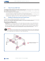
The metal detector METAL SHARK® 2 BD consists of at least two parts:
yy sensor head,
yy controller and
yy optionally conveyor belt and reject device.
Sensor Head
Controller
Aperture
Display
Keyboard
Aperture Height
Control Box Lid
Mounting Bolt
Software Version 1.10a and higher
19
METAL SHARK® 2 BD Operator’s Manual
20
Software Version 1.10a and higher
Chapter 7 – Transport
7.
Transport
7.1.
Safety & Protection Instructions
yy
yy
yy
yy
yy
yy
yy
yy
yy
yy
yy
Danger !
To prevent damage to the machine and hazardous injuries when transporting and
installing the machine it is absolutely essential that you keep in mind the following
instructions:
yyOnly qualified personnel considering safety instructions is allowed to transport
and install the metal detector.
The machine may only be lifted using the frame provided.
To transport the machine only the hoisting and sling gear specified here may be used.
If the frame of the metal detector has rollers make sure that you only transport it on flat surface
When selecting suitable hoisting equipment always take the following weights into account:
depending on size and type, the metal detector can weigh up to 1,000 kg.
A third person must secure the transport route.
The transport routes must be cordoned off and secured so that no unauthorised persons
may enter the danger zone.
Sharp edges may cause injuries.
Suspended loads may drop. There is a risk of fatal injury – never stay under suspended
loads.
Parts lying unsecured on top of one another may slip and drop.
Only transport the metal detector after it is disconnected from the power supply.
Also read chapter “1. Safety Messages”.
Software Version 1.10a and higher
21
METALSHARK®2BDOperator’sManual
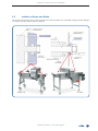
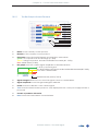
7.2.
Lifting
Choosesuitablehoistingequipment.Whenchoosinghoistingequipmentalwaysusepadded
cablesorstraps.Chainscouldleadtodamageofthemetaldetector.
Onlyliftthemetaldetectorattheframeprovided(markedgreeninfigurebelow)
Caution!
Neverlifttheentiresetofequipmentatthesensorheadorotherpartsmarkedred
(seefigurebelow).Theheavyweightoftheentiresetofequipmentmaycausedamagetothesensorhead.
=Lifthere!
=Donotlifthere!
22
SoftwareVersion1.10aandhigher
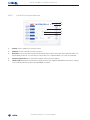
Chapter 8 – Mechanical Installation
8.
Mechanical Installation
The following points require special attention during installation:
yy Metal-free zone
yy Consider a gap between product and sensor head
yy Vibration
yy Feed of belt through sensor head
yy Mounting on conveyor / frame
yy Keep conveyor belt clean
yy Welding of transversal struts and contact points
yy Installation of sensor head
8.1.
Metal-Free Zone
A metal-free zone is required in front of and behind the sensor head aperture with a length corresponding to 1.5 times the aperture height.
Metal-free zone =
1.5x aperture height
Metal-free zone =
1.5x aperture height
Aperture Height
Software Version 1.10a and higher
23
METAL SHARK® 2 BD Operator’s Manual
8.2.
MinimumDistanceBetweenMotorandSensorHead
Between motor and sensor head there must be a minimum distance of 1.5x aperture height. Otherwise the metal detector is affected by the magnetic field of the motor.
1.5x aper ture he
8.3.
ight
GapBetweenSensorHeadandProduct
If the product has a strong product effect consider a 40 mm gap (minimum) between sensor
head and product for best metal sensitivity.
8.4.
Vibrations
y Install the metal detector so that it is exposed to as little vibration as possible in operation.
y Light vibrations do not affect the metal detector.
y However, metal alarm can be triggered by a hard shocks.
24
Software Version 1.10a and higher
Chapter 8 – Mechanical Installation
8.5.
FeedofBeltThroughSensorHead
y The detector is installed in the upper run of a conveyor belt.
y The transport belt is fed through the detector on a nonmetallic guide plate (such as a 16
mm plywood sheet) or tensioned to pass through the detector without contact.
y A minimum clearance of 5 mm must be maintained between the guide plate and the
detector.
y The inside of the detector opening may not be touched by the guide plate, belt or fibre
mat.
Nonmetallic guide plate
Gap min. 5 mm
8.6.
MountingonConveyor/Frame
y Ensure even and stable contact between metal detector and mounting bracket.
y The metal detector must not be subjected to any mechanical stress or tension
during the installation and during tightening of the mounting bolts.
y Before installing, scrape off paint from the conveyor or mounting frame around
all of the mounting holes for the metal detector. All of the mounting bolts must
have good electrical contact to the conveyor or mounting frame.
Software Version 1.10a and higher
✕
25
METAL SHARK® 2 BD Operator’s Manual
8.7.
KeepConveyorBeltClean
The transport belt must be kept absolutely clean. Even small metal particles and contamination
could trigger a metal alarm on cycle of the transport belt.
Theconveyormustbecleaned of metal swarf and dust before installation. Do not unpack the
belt until immediately before installation.
y Do not walk on the conveyor belt without clean protective shoe covers or other protective
measures. Visible or invisible shoe prints may contain metal particles.
y Ensure that the belt is well-covered, e.g. with cardboard, before welding or grinding. Hot
welding slag or grinding sparks can embed themselves in the surface of the belt.
8.8.
WeldingofTransversalStrutsandContactPoints
Check conveyor drawings and installation constructions:
Are there any designated welding spots on the conveyor or base frame in the range of the metal
detector, which must be welded after installation of conveyor and base frame?
Mounttheseweldingpoints!
Background: The measuring field of the metal detector indicates a very small electrical
current(pA)inthemetalpartsoftheconveyor.Slightestelectricalchangesonconveyor
frame(forexample:contactresistanceataboltedconnectionisbeingchangedabout
0,1 Ohm) can take effect to the measuring field and a metal alarm can be triggered.
Onlyaweldedconnectioninsuresinperpetuityaconstantohmicresistance.
Caution!
Always attach the grounding clamp of the welding unit directly next to the welding spot.
Do not under any circumstances allow welding current to flow through the metal detector. This will lead to the destruction of the metal detector!
Weld transversal struts
here (do not bolt)
26
Software Version 1.10a and higher
Chapter 8 – Mechanical Installation
8.9.
Isolation of Drums and Shafts
All drums and shafts have to be mounted one side isolated, for example using a plastic flange
housing or plastic sleeve (refer to figure).
INTRALOX
PU belt
Software Version 1.10a and higher
27
METAL SHARK® 2 BD Operator’s Manual
28
Software Version 1.10a and higher
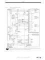
Chapter 9 – Electrical Installation
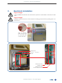
9.
ElectricalInstallation
HighVoltage!
Only qualified electricians are allowed to perform work inside of electrical cabinets.
HighVoltage!
Hazard of electrical shock. Disconnect incoming power before opening the control box lid.
Use a metric
Allen key 4 mm
to unscrew the
control box lid.
Mainboard
Power
Board
Supply
Terminals of the
Mainboard
Terminals of the
Power Supply Board
Software Version 1.10a and higher
29
METAL SHARK® 2 Operator’s Manual
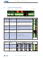
9.1.
Terminals of Power Supply Board
Internal
0VDC
+24V
DC
45 46 47
48 49 50
45 - 47
48 - 50
relay K2
51
52
53
relay K1
54
51 - 53
55
Fuse
L1
N
PE
1A T (slow) L1
N
PE PE
56
54 - 56
AC 47-63Hz
Ground
Ground potential for internal power supply
+ 24 V DC OUT
Internal Power supply source 24V/300mA
max
(total max. 400 mA accumulated at all 24V
outputs; inclusive of mainboard outputs)
Relay K2
51, 52, 53
Error alarm OUT
Closed line, potential free, switching
capacity:
230V AC at 5 A max or 30V DC at 5A max
Relay K1
54, 55, 56
Metal alarm OUT
Closed line, potential free, switching
capacity:
230V AC at 5 A max or 30V DC at 5A max
L1, N, PE
AC Power supply
IN
Mains power supply
85 – 250 V AC / 47 – 63 Hz / 100 VA
51
45, 46, 47
48, 49, 50
Description
48 49 50
Function
45 46 47
Terminal #
PE
52
53
54
55
56
L1
N
PE
PE
9.2.
Terminal #
Relay K1, K2 - Function
Function
Relay Status
Power OFF
51
52
53
Relay K2
Error alarm OUT
54
55
56
Relay K1
Metal alarm OUT
30
ERROR
NORMAL
Software Version 1.10a and higher
METAL
Chapter 9 – Electrical Installation
9.3.
Terminal #
Terminals on the Mainboard
Name
Ratings
Function
0-10V DC
Analogue input, application specific (when
METAL SHARK® BIG pba = „Matt height,
Board thickness, test stick diameter”)
2, 4, 6,
AGND
8
0V Analogue
Analogue Ground
3
AIN2
0-10V DC
Analogue input, belt speed
5, 7
AOUT1,
AOUT2
0-10V DC
Analogue output, application specific
9, 11,
13, 15,
IN1 - IN8
17, 19,
21, 23
24V DC,
10kΩ,
3mA
Logic input, functions refer to chapter "13.2.5. IN/OUT MENU"
(Parameters E80 - E115)
10, 12,
14, 16,
+24V
18, 20,
22, 24
24V DC
+24V DC source for logic inputs
(total max. 400 mA accumulated at all 24V outputs; inclusive of power supply board outputs)
25, 27,
29, 31, OUT1 33, 35, OUT8
37, 39
24V DC,
Logic output, functions refer to chapter "13.2.5. IN/OUT
MENU"
(Parameters E120 - E155)
(total max. 400 mA accumulated at all 24V outputs; inclusive of power supply board outputs)
26, 28,
30, 32,
0V
34, 36,
38, 40
0V DC
Logic ground for logic outputs
41
TX
-5...+5V
digital
RS232 Asynchronous Serial-Data (transmitter) output.
42, 44
GND
0V DC
Ground for RS232
43
RX
-5...+5V
digital
RS232 Asynchronous Serial-Data (receiver) input.
1
AIN1
Caution!
The sum of all +24 VDC loads must not exceed 400mA, including all loads connected to
mainboard (terminals 9 -40) and power supply board (terminals 48-50).
Software Version 1.10a and higher
31
METAL SHARK® 2 BD Operator’s Manual
9.4.
Wiring Diagram Examples
This chapter shows two typical METAL SHARK® 2 wiring examples with CASSEL conveyor belt controls. The
specific wiring diagram for your metal detector is shipped along with the documentation.
9.4.1.
Belt Controls STR1 and STL1
Caution!
The sum of all +24 VDC loads must not exceed 400mA, including all loads connected to mainboard (terminals 9 -40) and power supply board (terminals 48-50).
32
Software Version 1.10a and higher
Chapter 9 – 9
9.4.2.
Belt Controls STR2 and STL2
Caution!
The sum of all +24 VDC loads must not exceed 400mA, including all loads connected to mainboard (terminals 9 -40) and power supply board (terminals 48-50).
Software Version 1.10a and higher
33
METAL SHARK® 2 BD Operator’s Manual
34
Software Version 1.10a and higher
Chapter 10 – Control Panel and Main Screens
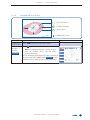
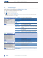
10.
ControlPanelandMainScreens
10.1.
TheControlPanel
This chapter describes the functions of the control panel's keys and LEDs.
OK
TEST
TEACH
OPTIMIZE
MENU
MOZZARELLA
PRODUCT
5
Total
Metal
7
0
0%
75 mV
168.50°
ERROR! LED indicates a malfunction (more information: chapter "13.1.ErrorMessages").
OK LED indicates that the metal detector is working properly.
OKis displayed when the metal detector is working properly.
STOP is displayed when the conveyor belt is stopped (only when using a conveyor belt)
!MET is displayed in case of a metal alarm.
!ERR is displayed in case of an error.
FunctionKeys: On the Main Screen the keys are preset to PRODUCT, TEST, TEACH, OPTIMIZE
and MENU. In the menu you can assign shortcuts to the upper four keys by pressing the particular key for two seconds in the desired menu.
METAL LED indicates a metal alarm.
ESC-Key: Press ESC to leave the current menu item or data entry. Keep it pressed to return
to the Main Screen.
Arrow-Keys: Press to choose the menu items and to change the Main Screen Mode
(More information: chapter ”8.2.TheMainScreens”). When entering names and numbers
you select the previous or next character with .
Plus/Minus-Keys: Press +/– to change parameters and to switch between functions.
OK-Key: Press OK to confirm a selection or entry.
Software Version 1.10a and higher
35
METAL SHARK® 2 Operator’s Manual
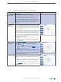
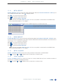
10.2.
TheMainScreens
The METAL SHARK® 2 has three graphic screen modes:
y 2D plot (teach area),
y bar graphs (histogram) and
y scope (oscilloscope)
Press on the main screen to change the screen mode.
!MET MOZZARELLA
5
PRODUCT
TEST
TEACH
OPTIMIZE
MENU
Total
Metal
276
34
12 %
364 mV
16.97°
bar graphs (default)
We recommend to use the Bar Graph Screen
for daily operation. It indicates how close the
signals were to a metal alarm. Moreover, the
histogram shows the signals of products and
metal alerts that have occurred in the last
hours.
For the different screen elements refer to "8.2.1.
TheBarGraph'sScreenElements".
Press
!MET MOZZARELLA
5
PRODUCT
2D plot
We recommend the 2D Plot Screen to look for
details of a single product sample.
For the different screen elements refer to "8.2.2.
The2DPlot'sScreenElements".
TEST
TEACH
OPTIMIZE
MENU
Total
Metal
276
34
12 %
364 mV
16.97°
Press
!MET MOZZARELLA
PRODUCT
TEST
TEACH
OPTIMIZE
MENU
36
Total
Metal
276
34
12 %
5
scope
We recommend that only technicians use the
Scope Screen. It shows in detail the signal of
short events.It scales automatically. However,
when you press OPTIMIZE you can adjust the
X-axis, Y-axis and time interval of one grid.
For the different screen elements refer to "8.2.3.
TheScope'sScreenElements".
116 mV
2.66°
Software Version 1.10a and higher
Chapter 10 – Control Panel and Main Screens
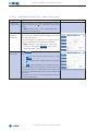
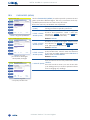
10.2.1.
The Bar Graph's Screen Elements
!MET MOZZARELLA
PRODUCT
5
TEST
TEACH
OPTIMIZE
MENU
Total
Metal
276
34
12 %
364 mV
16.97°
Name of the currently chosen product.
Number of the currently chosen product.
Histogram shows the last 232 signals and what they were about:
green = Good product in secure range (0 - 80%)
yellow = still good product, but almost identified as metal (80 - 100%)
red = metal alarm (>100%)
Bargraph shows the current signal amplitude as described below:
0 - 80 % = product signal
80 - 100 % = still good product, but almost identified as metal (80 - 100%)
over 100 % = metal alarm
Metal threshold (always 100 %)
Signalstrenghin% shows how close the signal comes to a metal alarm.
Signalamplitude shows the signal strenght in millivolts.
Phase shows the direction of the current signal.
Total shows the total number products. Only displayed if the conveyor is equipped with a
photocell.
Percentofproductswithmetal.
Metal shows the total number of metal alarms.
Software Version 1.10a and higher
37
METAL SHARK® 2 Operator’s Manual
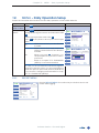
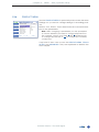
10.2.2.
The 2D Plot's Screen Elements
!MET MOZZARELLA
PRODUCT
5
TEST
TEACH
OPTIMIZE
MENU
Total
Metal
276
34
12 %
364 mV
16.97°
Name of the currently chosen product.
Number of the currently chosen product.
Reddots show measured values that left the teach area. Normally, this happens with contaminated products. In case the products are not contaminated you have to optimize.
Productsignaldots show measured value of the product signal.
Teacharea displays the tolerance range in which the signal is identified as product. All signals outside the teach area are identified as metal.
38
Software Version 1.10a and higher
Chapter 10 – Control Panel and Main Screens
10.2.3.
The Scope's Screen Elements
!MET MOZZARELLA
PRODUCT
5
TEST
TEACH
OPTIMIZE
MENU
Total
Metal
276
34
12 %
116 mV
2.66°
Name of the currently chosen product.
Number of the currently chosen product.
Reddots show signal amplitude of the X-channel.
Greendots show signal amplitude of the Y-channel.
t: shows the time interval of one grid square.
X: indicates the grid spacing of the X-channel in millivolt.
Y: indicates the grid spacing of the Y-channel in millivolt.
Software Version 1.10a and higher
39
METAL SHARK® 2 Operator’s Manual
40
Software Version 1.10a and higher
Chapter 11 – Initial Parameter Setup (all types, except BIG pba)
11.
Initial Parameter Setup (all
types, except BIG pba)
After the mechanical and electrical installation you have to set up a few parameters. The steps
below help you to put the metal detector into first operation.
Note: Step 3, Step 4 and Step 5 are not required if the metal detector is supplied as
ready-system, e.g. with pipeline, reject device or conveyor. CASSEL factory sets these parameters for ready-systems.
Switch power supply on
Set LANGUAGE.
Note: For more information refer to chapter “13.2. SYSTEM MENU”.
Set SPEED mm/s.
Note: For more information refer to chapter “13.2. SYSTEM MENU”.
Set IN/OUT MENU.
Note: For more information refer to chapter “13.2.5. IN/OUT MENU”.
Set up REJECT MENU.
Note: For more information refer to chapter “13.1.1. REJECT MENU”.
TEACH product.
Note: For more information refer to chapter “11.3. TEACH - Add New
Product”.
Software Version 1.10a and higher
41
METAL SHARK® 2 Operator’s Manual
42
Software Version 1.10a and higher
Chapter 12 – Daily Operation Overview
12.
DailyOperationOverview
This chapter explains what steps you have to take in the daily operation of the metal detector.
OK NO PRODUCT
1
Switch on the metal detector’s power supply. After having auto-calibrated itself the METAL SHARK® 2 displays
the main screen.
PRODUCT
TEST
Power on
TEACH
OPTIMIZE
Total
Metal
MENU
0
0
More information:“8.ControlPanelandMainScreens”
57 mV
123.97°
0%
OR
TeachNewProduct
Set product and press NEXT
Select&EditProducts
OK NO NAME
OK CAMEMBERT
-
SELECT
EDIT
COPY
DELETE
EXIT
4
# PRODUCT NAME
Total
Metal
0
0
Print
IFS/
HACCPReport
Total
Metal
EXIT
0
0
More information:
25 mV
166.50°
0%
Press TEACH to add a new product to the
product list. The teach assistant starts. Set up
a new product. Press NEXT and feed product
samples through the sensor.
Product”
“11.3. TEACH – Add New
25 mV
166.50°
0%
OptimizeStability&Sensitivity
Set TOL. X to make X max. 80%
!MET MOZZARELLA
TOL. Y 1.2
EXIT
Total
Metal
276
34
TEACH
OPTIMIZE
MENU
Total
Metal
276
34
5
TEST
TEACH
OPTIMIZE
276
34
IFS/HACCP
PRODUCT REPORT - SUMMARY
From date/time:
2008-05-03 08:02:54
To date/time:
2008-05-05 18:15:21
IFS/HACCP
Number
of PVS tests:
4
Number of passed PVS tests:
3
Number of failed PVS tests:
1
MENU
Metal Events:
34
Product Counter:
276
Percent
8
TEST Metal:
276
34
12 %
25 mV
154.26°
12 %
364 mV
1.97°
Best stability when X below 80% and Y below
80%.
Best sensitivity when X over 60% and Y over 60%.
Press OPTIMIZE.
Stability = best,
when below 80 %
Sensitivity = best,
when over 60 %
If X-bar over 80%
press TOL. X and +
If X-bar below 60%
press TOL. X and -
If Y-bar over 80%
press TOL. Y and +
If Y-bar below 60%
press TOL. Y and -
More information:
Stability&Sensitivity”
“11.4. OPTIMIZE – Improve
Optionally, press TEST to test the metal detector’s sensitivity. If an automatic test is set up, the test starts automatically.
Now start your normal production. Metal alarms are indicated on the screen: !MET.
More information: “11.2. TEST – Check Metal Detector’s
364 mV
1.97°
12 %
OK MOZZARELLA
Total
Metal
5
TEST
PRODUCT
EXIT
✕
364 mV
1.97°
PRODUCT
OK MOZZARELLA
Total
Metal
12 %
OK MOZZARELLA
informa-
MENU
5
TOL. X 1.2
“11.1.
PRODUCT – Select
and Edit Existing
Products”
Check
Performance
&
Start Normal Production
005
MOZZA
300000
precise
-
Select existing product from product list:
P re s s P R O D U CT to
open the product list.
Press �� to navigate
through the product
list and press SELECT
to select the product.
More
tion:
PRODUCT NR.
PRODUCT NAME
PRODUCT IS...
FREQ. SELECT
TEACH MODE
NEXT
0 NEUTRAL
1 GOUDA
2 BRIE
3 EDAMMER
4 CAMEMBERT
5 NO NAME
6 NO NAME
7 NO NAME
1
TEACH Step 1: Set Product
-
Performance”and“12.2.TESTMENU”
5
Optionally, you might want to print IFS/HACCP Reports
or send them to a connected PC. Press MENU. Enter the
REPORT MENU and open IFS/HACCP REPORT. Then
press OK to print it.
More information:“12.1.REPORTMENU”
Software Version 1.10a and higher
43
METAL SHARK® 2 Operator’s Manual
44
Software Version 1.10a and higher
Chapter 11 – Daily Operation
11.
DailyOperation
You always need these functions in the daily operation of the metal detector.
11.1.
PRODUCT–Select&EditExistingProducts
Step
Operation
Screen
1. Return to
Press ESC to return to the main screen.
Main Screen
2. Open
product list
Press PRODUCT to open the product list.
Press to navigate through the product list.
The following functions are available:
SELECT
or OK
selects the product marked blue
in the screen (in the example you
would select CAMEMBERT).
EDIT
opens the PRODUCT MENU where
you can edit the settings of the
respective product. (“12.4.PRODUCTMENU”)
COPY
copies the currently selected
product, in the example MOZZARELLA, to the selected product
memory, here CAMEMBERT. Confirm with OK.
DELETE
deletes the selected product
memory, in the example CAMEMBERT. Confirm with OK.
Software Version 1.10a and higher
OK MOZZARELLA
SELECT
EDIT
COPY
DELETE
EXIT
5
# PRODUCT NAME
0
1
2
3
4
5
6
7
NEUTRAL
GOUDA
BRIE
EDAMMER
CAMEMBERT
MOZZARELLA
NO NAME
NO NAME
Total
Metal
0
0
0%
25 mV
166.50°
45
METAL SHARK® 2 Operator’s Manual
11.2.
TEST–CheckMetalDetector'sPerformance
Step
Operation
Screen
1. Return to
Press ESC to return to the main screen.
Main Screen
2. Start TEST
Press TEST to start the PVS Test (Performance Val- Feed test balls with no product through sensor
OK MOZZARELLA
idation System Test).
PVS
TEST
PRODUCT
The screen prompts the required test stick size. FE 0.7 mm
TEST
The help text indicate whether you are to feed Waiting
the test stick with or without a product sample.
TEACH
ESC aborts the test.
Note: Refer to chapter “12.2. TEST MENU”
tosetupthePVSTest(teststicksizes,etc.).
3. Feed
test sticks
through
sensor
OPTIMIZE
(Esc)
MENU
(Ok) Total
Metal
11
0
0%
28 mV
157.12°
Feed a test stick of the indicated size through Feed test balls with no product through sensor
OK MOZZARELLA
the sensor.
Note: Do not feed products through the
sensor.
The display shows:
Waiting
when it is waiting for the relative
test stick.
Passed
when the correct test stick size has
been detected.
Skipped
when you have set the size of the
relative test stick to zero.
No Signal
when the time set for the parameter PVS WINDOW min is up and the
metal detector has not detected
a test stick.
Big Signal
when the signal of the test stick is
bigger than the value set for max
mV. After 10 seconds it switches
back to Waiting and you can try
again.
5
PVS
TEST
PRODUCT
FE 0.7 mm
Passed
TEST
NFE 1.0
Passed
SS
1.2
TEACH
Waiting
5
OPTIMIZE
(Esc)
MENU
(Ok) Total
Metal
11
0
0%
28 mV
157.12°
Repeat the test for every kind of metal configured in the TEST MENU to secure that the metal
detector works properly.
4. Test completed
As soon as the METAL SHARK® 2 has detected all Feed test balls with no product through sensor
test sticks the test is completed and the metal OK MOZZARELLA
PVS
TEST
PRODUCT
detector switches to normal mode. You can now FE
0.7 mm
Passed
continue with the normal production process.
TEST
NFE 1.0
You can later check the test results in the IFS/ Passed
SS
1.2
TEACH
Passed
HACCP REPORT (“12.1.1.IFS/HACCPREPORT”)
OPTIMIZE
(Esc)
MENU
46
Software Version 1.10a and higher
(Ok) Total
Metal
11
0
0%
28 mV
157.12°
5
Chapter 11 – Daily Operation
11.3.
Step
TEACH–AddNewProduct
Operation
Screen
1. Return to
Press ESC to return to the main screen.
Main Screen
2. Start
teach
assistant
Press TEACH to start the teach assistant.
Use to navigate through the menu.
Set product and press NEXT
OK NO NAME
NEXT
1
TEACH Step 1: Set Product
PRODUCT NR.
PRODUCT NAME
PRODUCT IS...
FREQ. SELECT
TEACH MODE
001
NO NAME
dry
300000
precise
EXIT
3. Choose
PRODUCT NR.
Total
Metal
0
0
25 mV
166.50°
0%
Set product and press NEXT
Go to PRODUCT NR. (D005).
OK NO NAME
Press +/- to choose the desired product number. TEACH Step 1: Set Product
Confirm with OK.
PRODUCT NR.
005
Note: Product 0 is set to neutral and can
notbechanged.
-
NEXT
PRODUCT NAME
PRODUCT IS...
FREQ. SELECT
TEACH MODE
1
dry
300000
precise
EXIT
4. Choose
PRODUCT
NAME
Go to PRODUCT NAME (D010).
Press OK to edit it.
Press +/- to change the current letter.
Press to select the previous/next letter.
Note:YoucanonlyuseLatincharacters.
Confirm the name with OK.
Total
Metal
0
0
25 mV
166.50°
0%
Set product and press NEXT
OK NO NAME
NEXT
1
TEACH Step 1: Set Product
PRODUCT NR.
PRODUCT NAME
PRODUCT IS...
FREQ. SELECT
TEACH MODE
005
MOZZA
300000
precise
EXIT
Total
Metal
0
0
0%
25 mV
166.50°
Continued on next page
Software Version 1.10a and higher
47
METAL SHARK® 2 Operator’s Manual
Step
Operation
Screen
5. Select
product
characteristics
Set product and press NEXT
Go to PRODUCT IS... (D015).
5
OK MOZZARELLA
Press OK.
TEACH Step 1: Set Product
Press +/- to choose the characteristic that
PRODUCT NR.
005
PRODUCT NAME
MOZZARELLA
describes your product:
PRODUCT IS...
salty
NEXT
dry
Products with lit tle residual
moisture like powder and solid
products
EXIT
wet
Products with high amount of
moisture, but few salt or spice
content, e.g. sausages, meat,
fruits, vegetables
salty
Products with high salt content
and good conductivity, e.g.
cheese
frozen
Deep frozen
(-18°C/0°F)
melting
Deep frozen products with
lightly melted surface
alu foil
Products packaged in metalized film
plastic
Plastic granulate with graphite
vibration
Vibrations in the construction
shock
Hard knocks and shocks
optimize
All product tolerances are set
to x1.0 by default
neutral
no product ef fect. Run the
metal detector without TEACH.
Set METAL SENSE mV (D120)
only.
products
Confirm with OK.
Continued on next page
48
Software Version 1.10a and higher
300000
precise
FREQ. SELECT
TEACH MODE
Total
Metal
0
0
0%
25 mV
166.50°
Chapter 11 – Daily Operation
Step
Operation
Screen
6. Select frequency
Go to FREQ. SELECT (D020).
Press OK.
Press +/- to select the desired frequency.
Single-Frequency-Sensor: This parameter
cannot be changed.
Dual- or Four-Frequency-Sensor and
AUTO FREQUENCY (D115) set to yes:
FREQ. SELECT is determined automatically. You cannot change it.
Dual- or Four-Frequency-Sensor and
AUTO FREQUENCY (D115) set to no: You
can choose between the available sensor frequencies (only technicians).
Confirm with OK.
Set product and press NEXT
OK MOZZARELLA
NEXT
EXIT
quick
3 to 7 product samples are necessary for the teach process. The
product is taught with large tolerance but therefore faster.
As a result, the metal detector
does not detect with highest metal
detection performance. We recommend to optimize the sensitivity
afterwards using the OPTIMIZE-function.
precise
8 to 14 product samples are necessary for the teach process.
The result is that the metal detector
is almost optimally adjusted to the
product and, therefore, achieves
very good results. In most cases you
do not have to OPTIMIZE.
005
MOZZARELLA
salty
300000
Total
Metal
0
0
25 mV
166.50°
0%
OK MOZZARELLA
PRODUCT
IFS/HACCP
MENU
TEST
Go to TEACH MODE (D025).
Press OK.
Press +/- to select quick or precise:
PRODUCT NR.
PRODUCT NAME
PRODUCT IS...
FREQ. SELECT
TEACH MODE
-
EXIT
7. Select
TEACH
MODE
5
TEACH Step 1: Set Product
TEACH SETUP
PRECISE COUNT
TEACH TIME s
TEACH EXTERN
TEACH REJECT
REMOTE PRODUCT
AUTOMATIC TEACH
CONV. LENGTH mm
AUTO FREQUENCY
Total
Metal
0
0
5
✔ Level 3
10
15
yes
no
no
no
1000
yes
25 mV
166.50°
0%
Set product and press NEXT
OK MOZZARELLA
NEXT
5
TEACH Step 1: Set Product
PRODUCT NR.
PRODUCT NAME
PRODUCT IS...
FREQ. SELECT
TEACH MODE
005
MOZZARELLA
salty
300000
quick
EXIT
Total
Metal
0
0
0%
25 mV
166.50°
Confirm with OK.
8. Check
settings and
continue
Check your settings. Press NEXT to go to the next
teach step.
Continued on next page
Software Version 1.10a and higher
49
METAL SHARK® 2 Operator’s Manual
Step
Operation
Screen
9. Feed
products
through
sensor
Feed product samples through the sensor. The Please Feed Product
number of products depends on what you have OK MOZZARELLA
TEACH Step 2: Learning
set up for TEACH MODE:
quick
3 to 7 product samples
-
precise
8 to 14 product samples
-
5
EXIT
10. Teach
successful
Total
Metal
2
0
0%
344 mV
182.70°
As soon as the METAL SHARK® 2 has collected TEACH Successfull
all necessary data a help text confirms that the OK MOZZARELLA
TEACH Step 3: Finished
teach process has been successful.
The product is now added to the product list and the metal detector is adjusted to the product.
EXIT
50
Software Version 1.10a and higher
Total
Metal
4
0
0%
328 mV
177.12°
5
Chapter 11 – Daily Operation
11.4.
OPTIMIZE–ImproveStability&Sensitivity
Below two ways are described how to optimize the METAL SHARK® 2's sensitivity and stability. Typically, use OPTIMIZE after TEACH in case the result of the teach assistant is not satisfactory.
Note: For products with PRODUCT IS... set to neutral refer to "11.4.3. Optimize with
PRODUCTIS...settoneutral".
11.4.1.
Optimize with the Histogram
Step
Operation
Screen
1. Return to
Press ESC to return to the main screen.
Main Screen
2. Choose
bar graph
screen
Press until the bar graph screen is shown.
Note:Formoreinformationonthe2Dplot
refer to chapter "8.2.1. The Bar Graph
ScreenElements ".
The main screen example: Products frequently
give out metal alarms (red lines). Many products are only within the tolerance range (yellow
lines).
Press OPTIMIZE if these products are not contaminated.
3. Set
TOL. X and/
or TOL. Y
!MET MOZZARELLA
5
PRODUCT
TEST
TEACH
OPTIMIZE
MENU
Total
Metal
276
34
12 %
578 mV
2.37°
The yellow help text shows that you should Set TOL. X to make X max. 80%
5
change TOL. X and TOL. Y. A value between 60 !MET MOZZARELLA
and 80% is the optimal setting for best sensitivity TOL. X 1.2
at highest stability.
TOL. Y 1.2
Press TOL. X or TOL. Y.
Press +/- to increase/decrease the value.
Confirm with OK.
Total
276
578 mV
In the example we increase TOL. X and TOL. Y EXIT
Metal
34 12 %
2.37°
from 1.2 to 1.3.
Note:Formoreinformationontolerances
referto "13.1.3.ADVANCED(MENU)"
4. Check
result and
adjust
Due to increasing the tolerance the products Set TOL. Y to make Y max. 80%
5
OK MOZZARELLA
are not identified as metal anymore.
TOL. X 1.3
The histogram of the X-value show, however,
that the majority of the signals are still within the TOL. Y 1.3
tolerance range between 80 and 100%.
Consequently, “irregular products” may cause
metal alarms.
Total
623
566 mV
Therefore, increase TOL. X , in this example to 1.4. EXIT
Metal
38
6%
2.44°
Software Version 1.10a and higher
51
METAL SHARK® 2 Operator’s Manual
Step
Operation
Screen
5. Check
result and
adjust
Due to increasing TOL. X all signals are in the Set TOL. X to make X max. 80%
range below 80%. All histograms are now green. OK MOZZARELLA
TOL. X 1.4
Irregular products do not cause metal alarms.
TOL. Y 1.3
They are within the tolerance range.
The metal detector is now set up optimally. Only contaminated products cause metal alarms.
EXIT
52
Software Version 1.10a and higher
Total
Metal
907
38
4%
575 mV
1.66°
5
Chapter 11 – Daily Operation
11.4.2.
Optimize with the 2D Plot
= product effect
= tolerance range
= teach area
= PRODUCT Y TOL.
Step
Operation
Screen
1. Return to
Press ESC to return to the main screen.
Main Screen
2. Choose
2D plot
screen
and press
OPTIMIZE
Press until the 2D plot screen is shown.
Note:Formoreinformationonthe2Dplot
refer to chapter "8.2.2. The 2D Plot's
ScreenElements ".
In the example an irregular product causes a
wrong metal alarm (!MET). Press OPTIMIZE to optimize the teach-area (inside of the green line).
Software Version 1.10a and higher
!MET MOZZARELLA
5
PRODUCT
TEST
TEACH
OPTIMIZE
MENU
Total
Metal
276
34
12 %
364 mV
16.97°
53
METAL SHARK® 2 Operator’s Manual
Step
Operation
Screen
3. Increase
Now you have two options: Either you increase
tolerance or the tolerance (as described in the previous !MET MOZZARELLA
press FREEZE chapter) or you can press FREEZE which gives TOL. X 1.2
you the following options:
TOL. Y 1.2
Simple
Freeze
Records product signals over a
longer period of time. This way
you see how good the teach area
describes the product.
Fo r mo re I nfo rmati o n refer to
“11.4.2.1.SimpleFreeze”.
Add to
Teach
Area
Adds the signals of irregular products to the teach area.
Fo r mo re I nfo rmati o n refer to
“11.4.2.2.AddtoTeachArea”.
New
Teach
Area
Deletes the old teach area. The
products you feed through the sensor create the new teach area. The
settings are the same as the original TEACH.
Fo r mo re I nfo rmati o n refer to
“11.4.2.3.NewTeachArea”.
ZOOM lets you zoom in and out.
54
*A
zooms automatically
*1 - *40
zooms 1 to 40-fold
Software Version 1.10a and higher
5
ZOOM *A
FREEZE
EXIT
Total
Metal
276
34
12 %
364 mV
16.97°
!MET MOZZARELLA
TOL. X 1.2
TOL. Y 1.2
ZOOM *A
FREEZE
EXIT
Freeze Start
Simple Freeze (OK)
Add to Teach Area (+)
New Teach Area (-)
Exit (ESC)
Total
Metal
276
34
12 %
364 mV
16.97°
5
Chapter 11 – Daily Operation
11.4.2.1
Optimizewiththe2DPlot–SimpleFreeze
Step
Operation
Screen
1. Start Simple Freeze
Press OK to start Simple Freeze Mode.
Note: Please read chapter “11.4.2.
OptimizingwiththeTeachArea”first.
Simple Freeze displays all product signals since
you have started Simple Freeze. It shows how
optimally the metal detector is adjusted to your
product.
2. Increase/
decrease
tolerance
In the example the turquoise dots mark the
product signals that were recorded. The red cir- OK BRIE
cle is the teach area. The white area between TOL. X 2.0
the turquoise dots and the teach area is the tol- TOL. Y 2.0
erance range.
ZOOM *A
During Simple Freeze Mode metal detection is
enabled. Product signals that exceed the teach FREEZE
00:00:46
area are marked red and cause metal alarms.
Total
276
EXIT
Metal
34
To increase the metal detection performance
and to detect smaller metal contaminants you
decrease the tolerance.
5
12 %
234 mV
182.66°
Note: If too many irregular products are
rejected, as described in 11.4.1, increase
thetolerance.
3. Decrease
tolerance
Press TOL. X or TOL. Y
Press +/- to make the area smaller/bigger.
Confirm with OK.
Note: Increase / decrease TOL. X and
TOL. Yinsmallsteps(0.1).
In the example you see that the teach area
wraps itself around the product signals more
tightly. The grey lines show the teach area before
decreasing the tolerances.
4. Confirm
OK BRIE
5
TOL. X 1.8
TOL. Y 1.8
ZOOM *A
FREEZE
00:01:25
EXIT
Total
Metal
276
34
12 %
234 mV
182.66°
Decrease the tolerance until the teach area
wraps itself perfectly around the product sig- OK BRIE
TOL. X 1.5
nals.
Note:Keepinmindthatthelesstolerance
rangeyouleavethemoreoftenirregular
productsmightcausefalsemetalalarms.
Press FREEZE again to stop the Simple Freeze
Mode.
Software Version 1.10a and higher
5
TOL. Y 1.8
ZOOM *A
FREEZE
00:02:44
EXIT
Total
Metal
276
34
12 %
234 mV
182.66°
55
METAL SHARK® 2 Operator’s Manual
11.4.2.2
Step
Optimizewiththe2DPlot–AddtoTeachArea
Operation
Screen
1. Start Add
This mode lets you modify and extend an existto Teach Area ing teach area. Press + to start Add to Teach Area
Mode.
Note:Pleaseread“11.4.2.Optimizingwith
theTeachArea”first.
2. Feed
irregular
products
Now add the signals of irregular products to the
teach area by feeding these irregular products OK MOZZARELLA
through the sensor.
In the example you see that the original teach area is extended by the measured signals.
5
ZOOM *A
Note: Metal is not detected during this
process. Therefore, FREEZE ends automaticallyafterthreeminutes.
3. Confirm result
56
FREEZE
EXIT
Total
Metal
276
34
12 %
228 mV
16.77°
Press FREEZE.
5
OK MOZZARELLA
Press:
PRODUCT
y OK to save the new teach area / stop
TEST
FREEZE,
y + to collect more irregular product signals TEACH
or
OPTIMIZE
y ESC to quit and keep the old teach area.
Total
276
228 mV
Metal
34 12 %
16.77°
In the example you see that products that would EXIT
be rejected are now within the teach area and
thus in the desired range. They are not rejected
anymore.
Repeat this process if other irregular products
cause metal alarms.
Software Version 1.10a and higher
Chapter 12 – MENU – Daily Operation Setup
MENU–DailyOperationSetup
12.
Preset and automize the functions for the daily operation of the metal detector.
Step
Operation
Screen
1. Return to
Press ESC to return to the main screen.
Main Screen
Press MENU to open the menu.
5
OK MOZZARELLA
Navigate through the menu and submenus with PRODUCT
MAIN MENU
✔ Level 2
.
REPORT MENU
✔
✔
IFS/HACCP TEST MENU
Open the respective menu with OK.
PASSWORD
✔
PRODUCT MENU
✔
Press ESC at any time to abort your current oper- MENU
SYSTEM MENU
✖
FACTORY MENU
✖
ation
2. Open
Menu
✔
Marks menus that you are allowed
to enter.
✖
Marks menus that only users of a
higher password level are allowed
to enter.
When you press OK , however, you
are prompted to type in the correct
password.
Refer to chapter "12.3.PASSWORD
(MENU)" for more information.
TEST
EXIT
Total
Metal
276
34
25 mV
154.26°
12 %
OK MOZZARELLA
PRODUCT
IFS/HACCP
MENU
MAIN MENU
5
✔ Level 2
REPORT MENU
ENTER
PASSWORD
TEST
MENU
Level 3 access
PASSWORD
*****3MENU
PRODUCT
SYSTEM MENU
FACTORY MENU
✔
✔
✔
✔
✔
✖
TEST
EXIT
Total
Metal
276
34
12 %
25 mV
154.26°
In case you do not have the necessary rights to
enter the specifi c menu you are prompted to
enter the specific password (refer to illustration).
If you want to change passwords refer to chapter "12.3.PASSWORD(MENU)".
REPORT MENU
12.1.
OK MOZZARELLA
PRODUCT
IFS/HACCP
MENU
TEST
EXIT
REPORT MENU
IFS/HACCP REPORT
METAL REPORT
EVENT REPORT
METAL COUNTER
TOTAL COUNTER
PRINT
INTERFACE
BAUDRATE RS232
Total
Metal
276
34
12 %
✔ Level 2
5
Use the REPORT MENU to monitor the production and to automize data logging.
34
276
one by one
RS232
115200
25 mV
154.26°
Software Version 1.10a and higher
57
METAL SHARK® 2 Operator’s Manual
IFS/HACCP REPORT
12.1.1.
The IFS/HACCP REPORT (A005) shows detailed information about the production. It consist of
three parts that are described below: SUMMARY, METAL, EVENTS.
You can switch between the different types with +/-.
With you can scroll up and down.
Press ESC to return to the main menu.
Press OK to print the IFS/HACCP REPORT.
Note:SettheparameterPRINTtoreporttosetupaprinterconnectedtotheRS232interface.Moreinformation"11.1.6.PRINT".
OK MOZZARELLA
IFS/HACCP
PRODUCT REPORT - SUMMARY
From date/time:
2008-05-03 08:02:54
To date/time:
2008-05-05 18:15:21
IFS/HACCP
Number of PVS tests:
Number of passed PVS tests:
3
Number of failed PVS tests:
1
MENU
Metal Events:
34
Product Counter:
276
Percent
8
TEST Metal:
EXIT
Total
Metal
276
34
12 %
4
25 mV
154.26°
5
The SUMMARY shows the following information:
From date/time:
Indicates when the last report was printed.
To date/time:
Indicates the current time and date.
Number of
passed PVS
tests:
Indicates the number of PVS test that were
completed accordingly.
Number of failed Indicates the number of PVS test that were
PVS tests:
not completed accordingly.
Metal Events:
Indicates the number of metal events that
have occurred since the last report was
printed.
Indicates the number of products that have
Product Counter: gone through the sensor since the last report
was printed.
Percent Metal:
OK MOZZARELLA
IFS/HACCP
PRODUCT REPORT - METAL
0034 2008-05-05 17:22:24 P005 245 mV 132.88°
0033 2008-05-05 15:32:12 P005 225 mV 164.74°
IFS/HACCP
0032
2008-05-05 11:17:33 P005 211 mV 126.36°
0031 2008-05-05 10:56:34 P005 214 mV 175.56°
0030 2008-05-05 08:45:17 P005 227 mV 153.98°
MENU
0029 2008-05-04 19:41:43 P005 275 mV 144.54°
0028 2008-05-04 19:22:59 P005 264 mV 186.76°
0027
TEST2008-05-04 13:54:24 P005 199 mV 116.92°
0026 2008-05-04 11:44:23 P005 278 mV 175.53°
EXIT
Total
Metal
276
34
12 %
25 mV
154.26°
OK MOZZARELLA
IFS/HACCP
PRODUCT REPORT - EVENTS
0001 2008-05-01 08:02:54 [01] System started
0002 2008-05-01 08:18:52 [10] Teach: Successful
IFS/HACCP
0003
2008-05-01 08:19:34 [20] PRODUCT IS...=dry
0004 2008-05-01 08:20:14 [35] BALANCE FACTOR=5
0005 2008-05-01 08:23:15 [36] Set all products
MENU
0006 2008-05-01 08:42:31 [20] Freeze performed
0007 2008-05-01 08:43:25 [35] PRODUCT X TOL=1.5
0008
TEST2008-05-01 08:44:43 [35] PRODUCT Y TOL=1.5
0009 2008-05-01 08:47:10 [35] PRODUCT Y TOL=1.2
EXIT
58
Total
Metal
276
34
12 %
25 mV
154.26°
Indicates the ratio (%) of contaminated
products to the total number of products.
METAL shows detailed information about the specifi c metal
5 events. Here an example of how to read the list:
0034
number of the metal alarm.
2008-05-05
date the alarm occurred.
17:22:24
time the alarm occurred.
P005
product number.
245 mV
voltage that was measured.
132.88°
phase that was measured.
EVENTS shows all events since the last print out (max last 1024
5 events). Here an example of how to read the list:
0001
number of the event.
2008-05-05
date of the event.
17:22:24
time of the event.
[01]
code for the respective type of event.
System started
Indicates which parameter was changed or
what action was taken.
Software Version 1.10a and higher
Chapter 12 – MENU – Daily Operation Setup
METAL REPORT
12.1.2.
METAL REPORT (A010) shows the same information like the IFS/HACCP REPORT - METAL plus
two additional information. Press + to display these.
With you can scroll up and down.
Press ESC to return to the main menu.
Press OK to print the METAL REPORT.
Note:SettheparameterPRINTtoreporttosetupaprinterconnectedtotheRS232interface.Moreinformation"11.1.6.PRINT".
OK MOZZARELLA
METAL
REPORT
PRODUCT
0034 P005 245 mV 132.88° 600000 Hz 12%/800%
0033 P005 225 mV 164.74° 600000 Hz 12%/800%
IFS/HACCP
0032
P005 211 mV 126.36° 600000 Hz 12%/800%
0031 P005 214 mV 175.56° 600000 Hz 12%/800%
0030 P005 227 mV 153.98° 600000 Hz 12%/800%
MENU
0029 P005 275 mV 144.54° 600000 Hz 12%/800%
0028 P005 264 mV 186.76° 600000 Hz 12%/800%
0027
TESTP005 199 mV 116.92° 600000 Hz 12%/800%
0026 P005 278 mV 175.53° 600000 Hz 12%/800%
EXIT
12.1.3.
Total
Metal
276
34
12 %
The two additional pieces of information are:
5
600000 Hz
Sensor frequency for this product.
12%/800%
amplification of X and Y for this product.
25 mV
154.26°
EVENT REPORT
EVENT REPORT (A015) shows the same information like the IFS/HACCP REPORT - EVENTS. However, the data is not deleted at any time. The last 1024 events are always listed. For more information refer to “12.1.1.IFS/HACCPREPORT”.
With you can scroll up and down.
Press ESC to return to the main menu.
Press OK to print the EVENT REPORT.
Note:SettheparameterPRINTtoreporttosetupaprinterconnectedtotheRS232interface.Moreinformation"11.1.6.PRINT".
12.1.4.
METAL COUNTER
METAL COUNTER (A020) shows how many products have been contaminated.
Press OK and then + and - simultaneously to reset the counter to zero.
12.1.5.
TOTAL COUNTER
TOTAL COUNTER (A025): In case you have a conveyor belt with a photo cell the number of
products is counted and displayed here.
Press OK and then + and - simultaneously to reset the counter to zero.
Software Version 1.10a and higher
59
METAL SHARK® 2 Operator’s Manual
PRINT
12.1.6.
OK MOZZARELLA
PRODUCT
IFS/HACCP
MENU
TEST
EXIT
REPORT MENU
276
34
Note:Referto"12.2.5.IN/OUTMENU"and"7.3.Terminals
on the Mainboard" to connect a printer to the METAL
SHARK®2.
✔ Level 2
IFS/HACCP REPORT
METAL REPORT
EVENT REPORT
METAL COUNTER
TOTAL COUNTER
PRINT
INTERFACE
BAUDRATE RS232
Total
Metal
PRINT (A030): Protocol mode of optional printer.
5
12 %
34
276
one by one
RS232
115200
25 mV
154.26°
Default: off
12.1.7.
off
No output to interface
report
You can print various reports by pressing OK
in the report screens.
one by one
Each metal alert and event immediately
makes the printer print a message.
SharkDiag
for SHARK DIAGNOSE® software at Windows
PC
SharkNet
for SHARKNET® software at Windows PC
INTERFACE
INTERFACE (A035) sets the output for the data. Options are:
RS232
Sends data via RS232
Ethernet
Sends data via optional Ethernet or WLAN
to PC
Default: RS232
12.1.8.
BAUDRATE RS232
BAUDRATE RS232 (A040) sets the speed of the RS232 interface.
Default: 9600
12.1.9.
SHARKNET UNIT #
SHARKNET UNIT # (A045) sets the address of the controller when it is part of a SHARKNET®.
Default: 1
12.1.10.
MAIN SCREEN
MAIN SCREEN (A050) sets which screen is displayed after you switch on the METAL SHARK® 2.
Options are: 2D plot (teach area), bar graphs (histogram), scope (oscilloscope).
Default: bar graphs
12.1.11.
HISTOGRAM LIMIT %
HISTOGRAM LIMIT % (A055) sets a threshold. Only signals that exceed this threshold are displayed in the histogram.
Default: 20
12.1.12.
INFO SOFTWARE
INFO SOFTWARE (A060) shows the current software version installed on the METAL SHARK® 2.
60
Software Version 1.10a and higher
Chapter 12 – MENU – Daily Operation Setup
TEST MENU
12.2.
OK MOZZARELLA
PRODUCT
IFS/HACCP
MENU
TEST
EXIT
TEST MENU
✔ Level 2
AUTO PVS TEST
PVS FE mm
PVS FE max %
PVS NonFE mm
PVS NonFE max %
PVS SS mm
PVS SS max %
PVS FREQ hrs
Total
Metal
276
34
AUTO PVS
TEST (B005)
12 %
yes
0.7
1000
1.0
1000
1.2
1000
8
25 mV
154.26°
5
Use the TEST MENU to adjust the settings of the PVS test,
explained in “10.2.TEST–CheckMetalDetector’sPerformance“.
Note: After changing a parameter you are prompted
tochoosewhetheryouwanttochangeallproductsor
thecurrentlychosenone.Press +and -simultaneously
to change all products or OK to change the currently
chosenone.
sets up an automatic reminder reminding you to check the performance of
the metal detector.
Default: no
PVS FE mm
set the test stick size of the respective metal that is to be found.
(B010)
Note:IfyoudonotwanttotestacertainmetalsettherelativeparamPVS NonFE mm
etertozero.
(B020)
Default: depends on application
PVS SS mm
Range: 0 - 99.9 [Millimetres]
(B030)
set the percentage that is not to be exceeded during the test. If it is exceeded
PVS FE max %
an alarm is given out.
(B015)
Note:IfyoudonotwanttotestacertainmetalsettherelativeparamPVS NonFE max
etertozero.
% (B025)
PVS SS max % Default: depends on application
(B035)
Range: 0 - 9999
PVS FREQ hrs
(B040)
sets every how many hours a test is to occur if AUTO PVS TEST is set to yes.
Default: 24
Range: 1 - 500
PVS WINDOW
min (B045)
Time frame for testing after PVS appeared.
Default: 30
Range: 1 - 180
PVS ERROR
COUNT (B050)
sets how often you can skip or fail the PVS Test before the error message PVS
Test Elapsed is displayed.
Default: 3
Range: 1 - 999
PVS COUNT
METAL (B055)
If set to no the metal counter does not increase when detecting a test stick.
Default: no
PVS USE
PRODUCT
(B060)
If set to no the user is promted to feed the test stick without a product sample.
Default: no
Software Version 1.10a and higher
61
METAL SHARK® 2 Operator’s Manual
PASSWORD (MENU)
12.3.
PRODUCT-SELECT, TEST
OK MOZZARELLA
PRODUCT
IFS/HACCP
MENU
PASSWORD
5
✔ Level 2
OPEN LEVELS
LEVEL 1 PASSWORD
LEVEL 2 PASSWORD
LEVEL 3 PASSWORD
LOGOUT
2
***
***
***
OPEN LEVELS
(C005)
TEST
Total
Metal
EXIT
276
34
Level 1: e.g. for operators
TEACH, OPTIMIZE, REPORT MENU, TEST MENU
OK MOZZARELLA
PRODUCT
IFS/HACCP
MENU
PASSWORD
5
✔ Level 2
OPEN LEVELS
LEVEL 1 PASSWORD
LEVEL 2 PASSWORD
LEVEL 3 PASSWORD
LOGOUT
2
***
***
***
Total
Metal
276
34
25 mV
154.26°
12 %
Level 2: e.g. for
production manager
and quality manger
PRODUCT MENU, SYSTEM MENU
OK MOZZARELLA
PRODUCT
IFS/HACCP
MENU
PASSWORD
✔ Level 2
OPEN LEVELS
LEVEL 1 PASSWORD
LEVEL 2 PASSWORD
LEVEL 3 PASSWORD
LOGOUT
2
***
***
***
Sets the password for level 2 users, e.g. production or quality managers. Level 2 users
LEVEL 2 PASS- are allowed to TEACH and OPTIMIZE prodWORD (C015)
ucts, print reports and set up TEST.
Default: CM0002
Sets the password for level 3 users, e.g. company technicians. Level 3 users are allowed
LEVEL 3 PASS- to access and alter settings in the PRODUCT
WORD (C020)
MENU and SYSTEM MENU.
Default: CM0003
TEST
EXIT
Sets which password levels are open without
having to enter a specific password.
Sets the password for level 1 users, e.g. production line operators. Level 1 users are
LEVEL 1 PASS- allowed to SELECT products and TEST the
WORD (C010)
metal detector's functionality.
Default: CM0001
25 mV
154.26°
12 %
Use the PASSWORD (MENU) to set the specific passwords and
grant operators different rights. This way you ensure that only
qualified personnel has access to key functions.
Below the various parameters are explained:
5
Locks all password levels that are higher
than the level set for the parameter OPEN
LEVELS.
LOGOUT (C025)
Use this function when you are done with
your settings and you want to prevent others
from changing any settings.
TEST
EXIT
Total
Metal
276
34
12 %
25 mV
154.26°
Level 3: e.g. for
company technician
62
Software Version 1.10a and higher
Chapter 12 – MENU – Daily Operation Setup
PRODUCT MENU
12.4.
OK MOZZARELLA
PRODUCT
IFS/HACCP
MENU
TEST
EXIT
PRODUCT MENU
✔ Level 2
PRODUCT NR.
PRODUCT NAME
PRODUCT IS...
FREQ. SELECT
TEACH MODE
REJECT MENU
TEACH SETUP
ADVANCED
005
MOZZARELLA
Total
Metal
276
34
12 %
salty
300000
precise
✖
✖
✖
25 mV
154.26°
5
Use the PRODUCT MENU to preset all products with the same
settings or if you want to change settings of an existing product.
Refer to "10.3.TEACH-TeachNewProducts" for more information on the parameters.
Note: After changing a parameter you are prompted
tochoosewhetheryouwanttochangeallproductsor
thecurrentlychosenone.Press +and -simultaneously
to change all products or OK to change the currently
chosenone.
Only level 3 users can access the REJECT MENU, TEACH
SETUP and ADVANCED. They are explained in detail in the
next chapter.
Software Version 1.10a and higher
63
METAL SHARK® 2 Operator’s Manual
64
Software Version 1.10a and higher
Chapter 13 – MENU – General Settings
MENU–GeneralSettings
13.
These settings adapt the METAL SHARK® 2 controller to hardware like pusher, conveyor, sensor
head etc.
13.1.
PRODUCT MENU
13.1.1.
REJECT MENU
OK MOZZARELLA
PRODUCT
IFS/HACCP
MENU
REJECT MENU
✔ Level 3
DELAY mm
DURATION ms
METAL CONTACT
PUSHER TOL mm
METAL-PHOTO mm
BELT STOP PUSH
5
The REJECT MENU sets up the timing for reject devices and
photo cell triggering.
0
500
pulse
100
0
yes
TEST
EXIT
Total
Metal
276
34
DELAY mm
(D035)
12 %
25 mV
154.26°
Delays the metal output signal for a certain distance. Use this to setup the
proper reject timing.
The metal detector calculates a time delay based on DELAY mm and SPEED
mm/s.
Note: During the delay period other metal signals which occur are
storedinashiftregisterandarenotlost.
Default: 0 [Millimetres]
Range: 0 - 30,000 [Millimetres]
DURATION ms
(D040)
is the length of time in milliseconds for which the Metal signal relay remains
switched.
Sets the length of a metal output pulse signal. E.g. use this to setup how long
a reject signal remains active.
Note: Whilst the relay is switched on, other metal signals which occur
arestoredinashiftregisterandarenotlost.
Default: 500 [Milliseconds]
Range: 150 - 30,000 [Milliseconds]
Software Version 1.10a and higher
65
METAL SHARK® 2 Operator’s Manual
programs the function of the metal alarm outputs.
METAL
CONTACT
(D045)
pulse
Metal alarm as a pulse with the duration DURATION ms. Use
e.g. when pneumatic nozzles separate the metal
gf1
Drives reject flaps with gravity feed applications. Error = flap
in reject - position
gf2
Drives reject flaps with gravity feed applications. Error = flap
in ok - position
mesep
Metal separator model MESEP® SE
inline
Security drive of inline reject EX-PWC
hold
Standard value for belt stop with reset push button.
push1
Pusher with photo cell active 0V (synchronized reject signal).
push2
Pusher with photo cell active 24V (synchronized reject signal).
push3
Pusher without photo cell synchronization
Default: pulse
PUSHER TOL
mm (D050)
Tolerance for photo eye trigger. Preset by CASSEL.
Default: 30 [Millimetres]
Range: 0 - 999 [Millimetres]
sets the distance between metal detection and photo cell.
METAL-PHOTO
Default: depends on application
mm (D055)
Range: 0 - 200 [Millimetres]
BELT STOP
PUSH (D060)
66
yes: The conveyor stops when the pusher is activated.
Default: depends on application
Software Version 1.10a and higher
Chapter 13 – MENU – General Settings
TEACH SETUP
13.1.2.
OK MOZZARELLA
PRODUCT
IFS/HACCP
MENU
TEST
EXIT
TEACH SETUP
✔ Level 3
SENSE MIN mV
TEACH SENSE mV
QUICK COUNT
PRECISE COUNT
TEACH TIME s
TEACH EXTERN
TEACH REJECT
REMOTE PRODUCT
Total
Metal
276
34
SENSE MIN mV
(D065)
12 %
10
25
3
10
15
yes
no
no
5
In the TEACH SETUP you adjust the settings for the teach
assistant. For more information refer to chapter "11.3.TEACH-
AddNewProduct".
25 mV
154.26°
Defines the smallest possible sensitivity that the teach assistant can automatically set. For most cases setup according suggestion of yellow help line.
Note:Useproduct0whensettingupthisparameter
Range: 3 - 2,000
TEACH SENSE
mV (D070)
blanks out signals that are smaller than this value. TEACH SENSE mV prevents
the metal detector from recognizing e.g. noises as products. It should be at
least the value of SENSE MIN mV. Signals that are bigger are identifi ed as
products. Set this parameter as the yellow help text indicates.
Range: 3 - 2,000
QUICK COUNT
(D075)
defines the maximum number of product samples required for TEACH STEP 2 if
TEACH MODE is set to quick.
Default: 3
PRECISE
COUNT (D080)
defines the maximum number of product samples required for TEACH STEP 2 if
TEACH MODE is set to precise.
Default: 7
TEACH TIME s
(D085)
The teach assistant stops after TEACH TIME s is elapsed. You have to feed at
least one product sample during that time. In case you do not feed a product
the teach assistant stops and sets the highest possible sensitivity.
VERYIMPORTANT: TEACH TIME s must be high enough to get at least one
product signal. Otherwise the compensation fails!
Recommendations:
Product speed 100-200 mm/sec. TEACH TIME s = 45
Product speed 200-300 mm/sec. TEACH TIME s = 30
Product speed 300-500 mm/sec. TEACH TIME s = 20
Product speed above 500 mm/sec. TEACH TIME s = 15
Default: depends on application
Range: 2 - 300 [Seconds]
yes: teach assistant starts when a 24V PLC signal is provided to the appropriTEACH
ate input.
EXTERN (D090)
Default: no
TEACH REJECT yes: activates metal alarm during teach assistant.
(D095)
Default: no
Software Version 1.10a and higher
67
METAL SHARK® 2 Operator’s Manual
yes: sets PRODUCT 0 – 20 remotely according input voltage 0-10V at terminal
AIN1..
REMOTE
PRODUCT
(D100)
Note:RefertoServiceManualfordetailedinformation.
Note:AvailableonlyforconveyorssuppliedbyCASSEL
Default: no
AUTOMATIC
TEACH (D105)
yes: only one product sample is required for the teach process. The conveyor
belt goes back and forth feeding the product through the sensor automatically.
Note:MakesurethatCONV. LENGTH mm issetupcorrectly.
Default: no
sets the length of the conveyor belt for AUTOMATIC TEACH.
CONV. LENGTH
Default: 1,000 [Millimetres], should be set to actual value
mm (D110)
Range: 100 - 9,999 [Millimetres]
AUTO
FREQUENCY
(D115)
yes: In case of a two or four frequency sensor head the teach assistant chooses
automatically the best frequency automatically.
Default: no
sets the distance from photo cell to sensor end.
TEACH PHOTO
Default: 999 [Millimetres], should be set to actual value
mm (D117)
Range: 0 - 999 [Millimetres]
ADVANCED (MENU)
13.1.3.
OK MOZZARELLA
PRODUCT
IFS/HACCP
MENU
TEST
EXIT
ADVANCED
✔ Level 3
METAL SENSE mV
PRODUCT X TOL.
PRODUCT Y TOL.
AMPLIFICATION X
AMPLIFICATION Y
ATTENUATION
PHASE
PHASE TRACK
Total
Metal
276
34
METAL SENSE
mV (D120)
12 %
122
1.0
1.0
100%
100%
1/1
89.92
0.00
5
The ADVANCED (MENU) is for experts only. Product parameters
are automatically set during the teach assistant. This menu
allows to modify the product parameters manually.
25 mV
154.26°
sets the metal sensitivity and thus the threshold for metal detection. If set to
3000 mV metal detection for this product is deactivated and NOT ACTIVE is
displayed.
To determine which mV a particular metal object generates, refer to mV value
in the lower right corner of the display. Bear in mind that non-spherical metal
parts may generate different magnitudes depending on their orientation.
Magnetic metal parts produce a larger signal than non-magnetic metal parts.
Note:Normally,youonlyhavetosetMETAL SENSE mVforneutralproducts (PRODUCT IS... = neutral). The teach assistant presets METAL
SENSE mVforallotherproductsautomatically.
Default: set during TEACH
Range: 3 - 3,000
68
Software Version 1.10a and higher
Chapter 13 – MENU – General Settings
adds a tolerance range around the product effect. The tolerance range
prevents false alarms from irregular products. Increasing PRODUCT X TOL.
increases the teach area at the X-axis.
PRODUCT X TOL. is automatically added as a factor to the result of the teach
assistant. It is not altered by the teach assistant. Thus, it allows to preset a larger
tolerance range than the teach assistant automatically considers.
= product effect
PRODUCT X
TOL. (D125)
= tolerance range
= teach area
= PRODUCT X TOL.
Default: 1.0
Range: 0.0 - 9.9
adds a tolerance range around the product effect. The tolerance range
prevents false alarms from irregular products. Increasing PRODUCT Y TOL.
increases the teach area at the Y-axis.
PRODUCT Y TOL. is automatically added as a factor to the result of the teach
assistant. It is not altered by the teach assistant. Thus, it allows to preset a larger
tolerance range than the teach assistant automatically considers.
= product effect
PRODUCT Y
TOL. (D130)
= tolerance range
= teach area
= PRODUCT Y TOL.
Default: 1.0
Range: 0.0 - 9.9
Hardware amplification factor for the product effect (X channel). The larger
the product effect is, the smaller the AMPLIFICATION X value has to be. 3% is
the smallest hardware amplification.
Whenusingproductmemories1-120: AMPLIFICATION X is set automatically
AMPLIFICATION during teach process according to the following rule:
X (D135)
Very strong product effect amplitude = AMPLIFICATION X 3%
Low product effect amplitude = AMPLIFICATION X 200%
Default: set during teach process
Values: 3%, 6%, 12%, 25%, 50%, 100% and 200%
Software Version 1.10a and higher
69
METAL SHARK® 2 Operator’s Manual
AMPLIFICATION
Refer to AMPLIFICATION X.
Y (D140)
ATTENUATION
(D145)
attenuates the signal received from the sensor head.
Default: 1/1
Values: 1/1, 1/3, 1/10
The setting of the product phase helps to blank out any product effect. It is set
automatically during the TEACH process.
PHASE (D150)
Note: PHASE is only available with product 1 - 120, not with PRODUCT
000.
Default: 0.00°
adjusts the product's phase during normal operation to compensate slow
changes of the product effect phase. The product effect phase may change
depending on product temperature and composition.
PHASE TRACK The parameter PHASE TRACK indicates the increment with that the phase
is adjusted: The higher this value the stronger the phase tracking. E.g. a 0.10°
(D155)
means 0.10 degree tracking with each product or metal signal.
Default: 0.00°
Range: 0.00 - 10.00°
70
Software Version 1.10a and higher
Chapter 13 – MENU – General Settings
SYSTEM MENU
13.2.
OK MOZZARELLA
PRODUCT
IFS/HACCP
MENU
TEST
EXIT
SYSTEM MENU
276
34
SPEED mm/s
(E005)
Note: Most parameters here are factory preset. Only
adjust SPEED mm/s and LANGUAGE, unless you need
to adapt the metal detector to any special requirements.
✔ Level 3
SPEED mm/s
LANGUAGE
DATE/TIME MENU
AUTOSPEED MENU
CIP MENU
BRC MENU
IN/OUT MENU
FILTER MENU
Total
Metal
The SYSTEM MENU sets general and basic settings.
5
12 %
300
ENGLISH
✔
✔
✔
✔
✔
✔
25 mV
154.26°
For optimum signal evaluation the unit has to be adjusted to the velocity at
which the products are passed through the sensor. A correct SPEED mm/s setting is absolutely essential.
SHARK®BD: Adjust the setting to the belt speed at which material is passed
through the metal detector.
SHARK® BD supplied with conveyor HQ: SPEED mm/s is set automatically.
SHARK® GF, SHARK® GF compact: 2000 mm/sec recommended.
OTHERS: Set SPEED mm/s at which material is currently passed through the
detector.
Range: 100 - 9,999 [Millimetres per Second]
IMPORTANT NOTE: A correct calibration of the conveyor belt (with ± 2
m/minexactness)isabsolutelyessential.Otherwiselowermetaldetectionsensitivityistheresult!
LANGUAGE
(E010)
sets the language of the display texts.
DATE/TIME MENU
13.2.1.
OK MOZZARELLA
PRODUCT
DATE/TIME MENU
IFS/HACCP
SET DATE
SET TIME
✔ Level 3
2008-07-01
11:49:36
5
Date and time are used in the various reports of the REPORT
MENU. Adjustable parameters are: SET DATE (E015) and SET
TIME (E020).
MENU
TEST
EXIT
Total
Metal
276
34
12 %
25 mV
154.26°
Software Version 1.10a and higher
71
METAL SHARK® 2 Operator’s Manual
AUTOSPEED MENU
13.2.2.
OK MOZZARELLA
PRODUCT
IFS/HACCP
MENU
AUTOSPEED MENU
AUTOSPEED
BELT STOP mV
CAL SPEED mm/s
SPEED mm/s
Total
Metal
276
34
12 %
Only use the AUTOSPEED MENU if you know that a
0-10V or 4 - 20 mA speed signal is connected to the
AIN2 (input terminal #3).
✔ Level 3
yes
500
1800
300
The speed signal at AIN2 must be calibrated. The calibration
defines which speed corresponds to how many millivolts.
Twovaluesmustbecalibrated:
y The voltage in mV at AIN2 (input terminal #3) that corresponds to a belt speed of 0 mm/sec. (=belt stop);
y The voltage in mV at AIN2 (input terminal #3) that corresponds to a belt speed of CAL SPEED mm/s.
TEST
EXIT
Caution!
5
25 mV
154.26°
mV
CAL SPEED mV
BELT STOP mV
0 mm/s
AUTOSPEED
(E025)
CAL
SPEED
mm/s
belt speed
yes activates automatic setting of SPEED mm/s.
Set calibration voltage for belt speed = 0 mm/s (belt stop).
BELT STOP mV
(E030)
CAL SPEED
mm/s (E035)
Hint:TheyellowhelptextshowsthecurrentinputsignalatAIN2.
Default: 0
Range: 0 - 9,990
Enter a conveyor speed for the second setpoint.
Recommended setting is 50% of maximum belt speed.
Note:Measurethecurrentspeedwithatachometer.
Default: 0
Range: 0 - 9,990
Set calibration voltage for belt speed CAL SPEED mm/s.
CAL SPEED mV
(E040)
SPEED mm/s
(E005)
72
Hint:Theyellowhelptextshowsthecurrentinputsignal.
Default: 0
Range: 0 - 9,990
shows SPEED mm/s as calculated from input AIN2. For information only.
Software Version 1.10a and higher
Chapter 13 – MENU – General Settings
CIP MENU
13.2.3.
OK MOZZARELLA
PRODUCT
CIP MENU
IFS/HACCP
CIP Reject s
CIP Normal s
CIP Timeout min
✔ Level 3
1
1
5
MENU
5
The CIP MENU (CIP = Clean In Place) is for pipeline models
only (METAL SHARK® IN LIQUID).
If activated, the reject device toggles between positions
“NORMAL” (production) and “REJECT” as long as the CIP input
is in state HIGH. Cleaning fluid running through the product
pipes cleans all interior surfaces of the reject device.
TEST
EXIT
Total
Metal
276
34
12 %
25 mV
154.26°
CIP Reject s
(E045)
sets the time for how long the reject device is switched to position “REJECT”
(in seconds).
Default: 0
Range: 0 - 320 [Seconds]
CIP Normal s
(E050)
sets the time for how long the reject device is switched to position “NORMAL”
(in seconds)
Default: 0
Range: 0 - 999 [Seconds]
CIP Timeout min
(E055)
sets the maximum time the detector is in CIP-mode (in minutes). After this time,
the detector will switch to normal operation even if CIP input remains HIGH.
Next CIP can be activated only after CIP input has been reset to low.
Note:Refertoparameterstart cipinchapter"13.2.5.IN/OUTMENU".
Default: 1
Range: 0 - 999 [Minutes]
Software Version 1.10a and higher
73
METAL SHARK® 2 Operator’s Manual
BRC MENU
13.2.4.
OK MOZZARELLA
PRODUCT
BRC MENU
IFS/HACCP
REJECT CONFIRM
BIN FULL
LOW AIR
5
✔ Level 3
no
no
no
The BRC MENU allows you to configure the metal detector in
order to comply with the British Retail Consortium (BRC) Food
Technical Standard.
MENU
TEST
EXIT
Total
Metal
276
34
12 %
25 mV
154.26°
yes enables reject monitoring (using optional photo eyes). It thus checks
whether the contaminated product was indeed rejected.
Status of the metal detector will switch to “ERROR” if reject device fails.
REJECT
CONFIRM
(E060)
Note:Refertoparameterreject validinchapter"13.2.5.IN/OUTMENU".
Default: no
BIN FULL (E065)
yes enables reject bin monitoring (with optional photo eye). It thus checks
whether the rejection bin is full.
Note:Refertoparameterbin fullinchapter"13.2.5.IN/OUTMENU".
Default: no
LOW AIR (E070)
yes enables air pressure monitoring (with optional pressure sensor).
Status of the metal detector will switch to “ERROR” (i.e. relay K2 “OFF”) if the
air pressure is too low.
Note:Refertoparameterlow airinchapter"13.2.5.IN/OUTMENU".
Default: no
IN/OUT MENU
13.2.5.
OK MOZZARELLA
PRODUCT
IFS/HACCP
MENU
TEST
EXIT
74
5
IN/OUT MENU
✔ Level 3
INPUT LINE 1
INPUT LINE 2
INPUT LINE 3
INPUT LINE 4
INPUT LINE 5
INPUT LINE 6
INPUT LINE 7
INPUT LINE 8
conveyor on/off
input off
input off
input off
input off
input off
input off
input off
Total
Metal
276
34
12 %
Setup of the input and output switching lines of the metal
detector. Set up the parameters according to the devices
connected to IN1 - IN8 and OUT1 - OUT 8 terminals on the
mainboard.
Note: For more information refer to “7.3. Terminals on
theMainboard”.
25 mV
154.26°
Software Version 1.10a and higher
Chapter 13 – MENU – General Settings
Terminals on SHARK mainboard corresponding to INPUT LINE 1 - INPUT LINE 8:
INPUT LINE 1 = Terminal 9
INPUT LINE 3 = Terminal 13
INPUT LINE 5 = Terminal 17
INPUT LINE 7 = Terminal 21
INPUT LINE 2 = Terminal 11
INPUT LINE 4 = Terminal 15
INPUT LINE 6 = Terminal 19
INPUT LINE 8 = Terminal 23
Functions of INPUT LINE 1 - INPUT LINE 8 (E080 - E115):
met/err reset
HIGH: Return to normal operation mode after METAL or ERROR
conveyor on/off
Belt control push button input (START / STOP / RESET)
start teach
HIGH: Start TEACH
reject test
HIGH: Trigger reject device now.
reject valid
Connect feedback signal from reject device.
ERROR if no signal transition after METAL OUT
reject sync
Photo eye, triggers pusher to product centre
reject safety
LOW: Reject device is locked in position NORMAL, e.g. during cleaning.
keypad lock
HIGH: Keyboard is locked, no data entry possible. Typical application: Key
switch.
low air
Monitors compressed air.
LOW for more than 30sec.: Triggers Error 7: Low Air (refer to “14.1. Error Messages”).
start cip
HIGH: Activates CIP mode (refer to “13.2.3. CIP MENU”)
bin full
Monitors reject bin.
HIGH for more than 30 sec.: Triggers Error 6: Bin Full (refer to “14.1. Error Messages”)
met count reset
HIGH: Resets METAL COUNTER (A020)
false trip
HIGH: Sends a false alarm message to the SHARKNET® software
product 120
HIGH: PRODUCT NR. (D005) is set to 120.
LOW: PRODUCT NR. (D005) is set to original number.
met/err key
HIGH: Return to normal operation mode after METAL or ERROR (only available
with option: key switch)
booster ok
Monitors booster.
LOW triggers Error 17: Booster Error (refer to “14.1. Error Messages”)
Note: Only change this input when advised by CASSEL.
belt splice
HIGH: Sets sensitivity to SPLICE SENSE mV (E270)
LOW: Sets sensitivity to METAL SENSE mV (D120)
product LS
Photo eye signals product‘s edges during TEACH Step 2: Learning Software Version 1.10a and higher
75
METAL SHARK® 2 Operator’s Manual
test no reject
HIGH: activates metal test mode (only with option: key switch).
During test mode the conveyer is immidiately stopped when metal ist detected
(output 'error CW') - however, the metal alarm is neither counted nor entered
in the event report.
Timeout of the test mode is controlled by CIP Timeout min - after this time has
elapsed normal metal detection continues. While the test mode is active TEST
is displayed.
input off
Input is not active.
76
Software Version 1.10a and higher
Chapter 13 – MENU – General Settings
Terminals on SHARK mainboard corresponding to OUTPUT LINE 1 - OUTPUT LINE 8:
OUTPUT LINE 1 = Terminal 25
OUTPUT LINE 3 = Terminal 29
OUTPUT LINE 5 = Terminal 33
OUTPUT LINE 7 = Terminal 37
OUTPUT LINE 2 = Terminal 27
OUTPUT LINE 4 = Terminal 31
OUTPUT LINE 6 = Terminal 35
OUTPUT LINE 8 = Terminal 39
Functions of OUTPUT LINE 1 - OUTPUT LINE 8 (E120 - E155):
metal
HIGH if metal detected, refer to “13.1.5. REJECT MENU” for details
metal inverse
LOW if metal detected.
error
HIGH during normal operation, LOW if detector is not in normal operation
error inverse
LOW during normal operation, HIGH if detector is not in normal operation
met+err
HIGH if metal alarm or unit not in normal operation, LOW during normal
operation
met+err inv.
LOW if metal alarm or unit not in normal operation, HIGH during normal
operation
metal zero del
HIGH if metal detected, no DELAY mm (refer to “13.1.1. REJECT MENU”)
pv test
HIGH if last sensitivity test more than PV FREQ HOURS ago (refer to “11.2. TEST
- Check Metal Detector's Performance”)
dual freq
For dual frequency detectors only.
teach confirm
HIGH if TEACH ended successfully ("TEACH Successfull" displayed)
cip out
HIGH if detector is in CIP mode (refer to “13.2.3. CIP MENU” for details)
start conveyor
HIGH if conveyor on/off received a start signal
pusher
The outputs metal and pusher switch to active at the same time: However,
pusher switches back to inactive already after 1/3 of the time of DURATION
ms (but at least 40 ms). This way a pneumatic pusher is able to return to normal position during DURATION ms.
big metal
HIGH if big metal piece is detected - only BIG pba.
booster on
HIGH switches booster on
conv. forward
Internal function, not for common use
conv. reverse
Internal function, not for common use
metal CW
HIGH: if metal detected
LOW: automatically after 140 ms.
error CW
HIGH: like 'error'. When metal test mode is activated via key switch, also
when metal is detected. This way the conveyor of the checkweigher stops
when metal is detected during test mode.
output off
Output not active. Output remains LOW.
Software Version 1.10a and higher
77
METAL SHARK® 2 Operator’s Manual
FILTER MENU
13.2.6.
OK MOZZARELLA
PRODUCT
IFS/HACCP
MENU
FILTER MENU
✔ Level 3
VIBRATION mV
VIBRATION FILTER
BP FILTER
LP FILTER
GF MODE
5
The FILTER MENU sets filters to improve the detection reliability and suppress noise.
5
off
CCF
off
off
TEST
EXIT
Total
Metal
276
34
12 %
25 mV
154.26°
TosetVIBRATION mV:
1. Set PRODUCT 000, AMP X% 100, AMP Y% 100
2. Run the production line or the conveyor, but without products and without
VIBRATION mV metal.
(E160)
3. Read out the peak mV level.
4. Set VIBRATION mV to the maximum peak mV level plus 30%.
Default: 10
Range: 3 - 2,000
VIBRATION
FILTER (E165)
blanks out mechanical vibrations of the sensor head.
yes activates vibration filter.
The value of VIBRATION mV (above) controls the filter strength:
VIBRATION mVincreased: Better suppression of vibration noise, lower detection
sensitivity.
VIBRATION mVdecreased: Less suppression of vibration noise, better detection
sensitivity.
Default: no
Note:OnlychangethisfilterwhenadvisedbyCASSEL.
BP FILTER
(E170)
no filter = filter is deactivated. Do not use unless clearly instructed by CASSEL
FFT = special Filter mode. Do not use unless clearly instructed by CASSEL
CCF = default
Default: CCF
LP FILTER
(E175)
yes = Lowpass filter activated.
Default: yes
GF MODE
(E180)
yes enables fast metal detection. Gives a wide speed range. (for GF or fast
applications)
no = normal applications
Default:
no (conveyor applications with defined belt speed)
yes (applications with undefined speed)
yes (all gravity feed applications)
78
Software Version 1.10a and higher
Chapter 13 – MENU – General Settings
Software Version 1.10a and higher
79
METAL SHARK® 2 Operator’s Manual
FACTORY MENU
13.3.
OK MOZZARELLA
PRODUCT
FACTORY MENU
IFS/HACCP
SENSOR CALIB.
UTILITIES
✔ Level 4
✔
✔
MENU
5
The FACTORY MENU adopts the electronic cards to the sensor head.
Note: Never touch these parameters. All parameters
here are factory preset. Therefore, Password Level 4 is
requiredtochangesettingsinthemenu.Level3users
canenterthemenuandreadtheparameters.
TEST
EXIT
80
Total
Metal
276
34
12 %
25 mV
154.26°
Software Version 1.10a and higher
Chapter 14 – Trouble Shooting
14.
TroubleShooting
14.1.
ErrorMessages
Error 14:
Receiver Clipping
!ERR MOZZARELLA
PRODUCT
TEST
TEACH
OPTIMIZE
MENU
Total
Metall
276
34
12 %
344 mV
1.97°
5
In case of an error:
y the Error-LED lights up,
y the screen indicates !ERR,
y an error message is displayed.
Note: Please write down the number of the error and
talktothecompanytechnicianorcallaservicetechnicianofCASSELMesstechnik.
Error#
ErrorText
Cause
Remedy
Error 1:
Comp. Pre
y Sensor out of the y R e m o v e b i g y Turn on/off metal
metal object in
detector
alignment.
the detector
y Mainboard damy Contact techniaged.
cian
y Big metal object
in the detector.
Error 2:
Comp. Fine
y Mainboard dam- y Contact techni- y Turn on/off metal
aged.
cian
detector
Error 3:
Signal Clip
y S i g n a l p e r m a - y Use other prod- y Confirm with OK
nently too high
ucts
y Resta r t teach
for one minute.
y Contact techniprocess
cian
Error 4:
Reject
y R e j e c t d ev i c e y Confirm with OK y Confirm with OK
ha s b ee n t r i g and repeat test
g e re d b u t t h e y Contact technireject sensor did
cian
not detect the
rejection.
Error 5:
PVS Test Elapsed
y Performance
y Confirm with OK y Confirm with OK
va l i d a t i o n te s t
and repeat test
y Error reappears,
not done within
if period of time
preset period of
has expired and
time.
the PV test was
unsuccessful
Error 6:
Bin Full
y The bin is full or a y Empty bin
y Confirm with OK
product blocks y Contact techni- y E r ro r m e s s a g e
the sensor.
cian
reappears after
30 seconds, if bin
still full
Error 7:
Low Air
y Air pressure mon- y Check air pres- y Confirm with OK
itor signals low
sure supply
y E r ro r m e s s a g e
pressure.
y Contact technireappears after
cian
30 seconds, if not
enough air pressure
Software Version 1.10a and higher
Confirmation
81
METAL SHARK® 2 BD Operator’s Manual
Error #
Error Text
Cause
Error 9:
Keyboard
yy Key is jammed or yy Contact techni- yy Confirm with OK
keyboa rd con cian
yy E r ro r m e s s a g e
nector is loose.
appears until
keyboard is
replaced
Error 10:
Memory
yy M e m o r y p ro b - yy Turn on/off metal yy Confirm with OK
lem, pa rame detector
yy E r r o r
mesters can not be yy Contact technisage appears
saved
cian
until memory is
replaced
Error 12:
Check Belt
yy C o nveyo r b e l t yy Contact techni- yy Pu s h S tar t belt
s hould run but
cian
button
does not.
Error 13:
Output Wiring
yy Overload protec- yy Contact techni- yy Turn on/off metal
tion for outputs is
cian
detector
triggered.
Error 14:
Receiver Clipping
yy Receiver
yy Contact techni- yy Turn on/off metal
receives a signal
cian
detector
that is too large.
Error 15:
Sender Clipping
yy T r a n s m i t t e r i s yy Contact techni- yy Turn on/off metal
overloaded.
cian
detector
Error 16:
Transmitter Fault
yy External transmit- yy Contact techni- yy Confirm with OK
ter amplifier sigcian
na l s fa ult (e.g.
SPD)
Error 17:
Sender Power
yy Error in external yy Contact techni- yy Confirm with OK
amplifier
cian
yy Turn on/off metal
detector
Error 18:
Mat Height Input
yy Physical connec- yy C h e c k c a b l e yy Confirm with OK
tion erroneous
connection
yy Turn on/off metal
detector
Error 19:
Autospeed Input
yy Physical connec- yy C h e c k c a b l e yy Confirm with OK
tion erroneous
connection
yy Turn on/off metal
detector
14.2.
Reset to Default Values
14.2.1.
Passwords and Language
Remedy
Confirmation
Press OK , ESC and F5 for 1.5 seconds during start up (SHARK logo is displayed) to reset all passwords to the default values (CM0001 - CM0003). Also LANGUAGE is set to English.
14.2.2.
Factory Settings
Press OK , ESC and F1 for 1.5 seconds during start up (SHARK logo is displayed) to reset all parameters to the default settings preset by the factory.
82
Software Version 1.10a and higher
Chapter 14 – Trouble Shooting
14.3.
Problem Solving
14.3.1.
Problem: Still Considerable Metal Alarms After TEACH
Solution:
1. TEACH again. If metal alarms occur again:
2. Switch main screen to 2D plot (refer to “8.2. The Main Screens”)
3. OPTIMIZE (refer to “11.4. OPTIMIZE – Improve Stability & Sensitivity”)
4. FREEZE (refer to “11.4.2. Optimizing with the 2D Plot”)
5. Add to Teach Area (+) (refer to “11.4.2.2. Add to Teach Area”)
14.3.2.
Problem: Still Few Metal Alarms After TEACH
Solution:
1. TEACH again. If metal alarms occur again:
2. Switch main screen to bar graphs (refer to “8.2. The Main Screens”)
3. OPTIMIZE (refer to “11.4. OPTIMIZE – Improve Stability & Sensitivity”)
4. Adjust TOL. X and TOL. Y until signal of normal products = below
80% (refer to “11.4.1. Optimizing with the Histogram”)
14.3.3.
Problem: TEACH ends After Short Period of Time
Problem: TEACH ends after short period of time although no products have been fed through
sensor
Solution: Increase TEACH SENSE mV (D070) (refer to “13.1.2. TEACH SETUP”)
14.3.4.
Problem: Poor Metal Sensitivity After TEACH
Solution:
1. Is SPEED mm/s (E005) set up correctly? (refer to “13.2. SYSTEM MENU”)
2. TEACH again. If problem still occurs:
3. Switch main screen to bar graphs (refer to “8.2. The Main Screens”)
4. OPTIMIZE (refer to “11.4. OPTIMIZE – Improve Stability & Sensitivity”)
5. Does the display show below 60% when the product is fed
through the sensor? (refer to “8.2. The Main Screens”)
6. Adjust TOL. X and TOL. Y until signal of normal products = between
60 and 80% (refer to “11.4.1. Optimizing with the Histogram”)
Software Version 1.10a and higher
83
METAL SHARK® 2 BD Operator’s Manual
84
Software Version 1.10a and higher
Chapter 15 – Maintenance and Regular Inspections
15.
Maintenance and Regular Inspections
15.1.
Maintenance
The metal detector is a sensitive measuring device which serves to protect other machinery
from damage, thus preventing expensive, unscheduled interruptions of production. This manual
describes how to install, operate and adjust the sensitivity. The conveyor belt upon which the
metal detector is mounted is designed to ensure that the detector works accurately. The metal
detector will generally work safely and reliably without having to make additional adjustments
after the initial commissioning.
15.2.
Regular Inspections
Regular tests of the metal detector’s functions are very important to ensure safe operations. The
detector must be tested at least on a weekly basis. Additionally, it has to be tested after each
maintenance stop or after works have been performed near the detector. If the detector does
not function appropriately eliminate the malfunctions immediately; if not, machines protected
by the detector must be stopped.
It is recommended to regularly test the metal detector with standardised test objects and to
keep records of these tests in a log book. Metal testing spheres are generally supplied with the
detector.
A suitable metal testing object and a testing schedule should be established for the examination:
yy The testing object should be a sphere of the smallest diameter which detection is required.
The sphere can be glued to a piece of plastic or may be cast in. The sphere is passed
through the detector together with the product in order to observe whether a metal detection signal is issued.
yy The testing schedule should state when the detector is to be tested and by whom. Example: The electrician on duty on a given shift has to test the detector using the testing object
one hour after the start of each shift. The test results are recorded in the log book with the
date, time and signature. Example: Test object recognised, 24 August 2007, 08.30, signed,
Smith.
15.3.
Notes
Normally, CASSEL commissions to adjust the metal detector to find the smallest metal pieces possible. Therefore please consider the following notes:
Keep the conveyor belt clean: Finger marks and shoe prints, visible or not, may contain metal
particles.
Do not weld or grind near the detector or the conveyor without having covered the conveyor belt
with e.g. cardboard. Sparks may burn into the surface of the conveyor and thus permanently
contaminate the belt.
Do not change the conveyor belt construction without having asked the manufacturer of detector and belt.
Software Version 1.10a and higher
85
METAL SHARK® 2 Operator’s Manual
86
Software Version 1.10a and higher
Chapter 16 – Annex
16.
Annex
16.1.
Declarations
16.1.1.
CE - Declaration of Conformity
The producer
CASSEL Messtechnik GmbH
In der Dehne 10
37127 Dransfeld, Germany
certifies herewith that the machines metal detector type METAL SHARK® 2 BD
are in conformity with the provisions of the following EC Directive(s) when installed in accordance with the
installation instructions contained in the product documentation:
yy EG-Machinery Directive 2006/42/EC
yy EC-Directive electromagnetic compatibility 2006/95/EC
yy Electromagnetic Compatibility 2004/108/EC
The equipment complies with:
Safety:
EN ISO 12100-1
Safety of machinery - Basic concepts, general principles for design - Part 1:
Basic terminology, methodology
EN ISO 12100-2
Safety of machinery - Basic concepts, general principles for design - Part 2:
Technical principles
EN 60204-1
Safety of machinery - Electrical equipment of machines - Part 1: General
requirements
EN 61010-1
Safety requirements for electrical equipment for measurement, control
and laboratory use - Part 1: General requirements
EN 60529
Degrees of protection provided by enclosures (IP code)
Electromagnetic Compatibility (EMC) according to 61000-6-2/4:
EN 61000-3-3
Electromagnetic compatibility (EMC) - Part 3-3: Limits - Limitation of voltage changes, voltage fluctuations and flicker in public low-voltage supply
systems, for equipment with rated current <=16 A per phase and not subjected to conditional connection
EN 61000-4
Electromagnetic compatibility (EMC) - Part 4: Testing and measurement
techniques
EN 61000-6-2
Electromagnetic compatibility (EMC) - Part 6-2: Generic standards - Immunity for industrial environments
EN 61000-6-4
Electromagnetic compatibility (EMC) - Part 6-4: Generic standards - Emission standard for industrial environments
EN 55011
Industrial scientific and medical (ISM) radio-frequency equipment - Electromagnetic disturbance characteristics - Limits and methods of measurement
Herewith we declare that we followed the relevant safety norms and requirements for technical safety
and for explosion prevention for the intended use when constructing and producing this metal detector.
Structural changes which have effects on the technical information in this manual and on the intended
utilisation, and therefore convert the machine considerably, make this declaration of conformity invalid!
Dransfeld, 27. October 2009
Cord Cassel, Managing Director
Software Version 1.10a and higher
87
METAL SHARK® 2 Operator’s Manual
16.1.2.
Declaration of Manufacturer
The producer
CASSEL Messtechnik GmbH
In der Dehne 10
37127 Dransfeld, Germany
certifies herewith that the machines metal detector type METAL SHARK® 2 BD
are in conformity with the provisions of the following EC Directive(s) when installed in accordance with the
installation instructions contained in the product documentation:
yy EC-Machinery Directive 2006/42/EC
yy EC-Directive electromagnetic compatibility 2006/95/EC
yy Electromagnetic Compatibility 2004/108/EC
Herewith we declare that the described product is intended to be incorporated into machinery and must
not be put into service until the machinery into which it is to be incorporated has been declared in conformity with the provisions of the EU-directives 2006/42/EC.
The equipment complies with:
Safety:
EN ISO 12100-1
Safety of machinery - Basic concepts, general principles for design - Part 1:
Basic terminology, methodology
EN ISO 12100-2
Safety of machinery - Basic concepts, general principles for design - Part 2:
Technical principles
EN 60204-1
Safety of machinery - Electrical equipment of machines - Part 1: General
requirements
EN 61010-1
Safety requirements for electrical equipment for measurement, control
and laboratory use - Part 1: General requirements
EN 60529
Degrees of protection provided by enclosures (IP code)
Electromagnetic Compatibility (EMC) according to 61000-6-2/4:
EN 61000-3-3
Electromagnetic compatibility (EMC) - Part 3-3: Limits - Limitation of voltage changes, voltage fluctuations and flicker in public low-voltage supply
systems, for equipment with rated current <=16 A per phase and not subjected to conditional connection
EN 61000-4
Electromagnetic compatibility (EMC) - Part 4: Testing and measurement
techniques
EN 61000-6-2
Electromagnetic compatibility (EMC) - Part 6-2: Generic standards - Immunity for industrial environments
EN 61000-6-4
Electromagnetic compatibility (EMC) - Part 6-4: Generic standards - Emission standard for industrial environments
EN 55011
Industrial scientific and medical (ISM) radio-frequency equipment - Electromagnetic disturbance characteristics - Limits and methods of measurement
Herewith we declare that we followed the relevant safety norms and requirements for technical safety
and for explosion prevention for the intended use when constructing and producing this metal detector.
Structural changes which have effects on the technical information in this manual and on the intended utilisation, and therefore convert the machine considerably, make this declaration of manufacturer invalid!
Dransfeld, 27. October 2009
Cord Cassel, Managing Director
88
Software Version 1.10a and higher
Parameterbogen METAL SHARK® 2
Parameter List METAL SHARK® 2 BD/ Software Version 1.10a
Project: Date: Model: Unit #: ✔ 1-3 = Required Password Level to enter this menu
Code
Name
Read/
Write
Description
Setting
REPORT MENU (✔ 1)
A005
IFS/HACCP REPORT
Quality inspection report, printed to screen or printer
R
A010
METAL REPORT
Shows report about last metal alerts
R
A015
EVENT REPORT
Shows information about last events
R
A020
METAL COUNTER
Increased by each metal detection
R
A025
TOTAL COUNTER
Increased when product passes sensor
R
A030
PRINT
Print mode
R/W
1
2
3
4
5
A035
INTERFACE
Interface protocol
R/W
1 RS232
2 Ethernet
1
2
3
4
5
A040
BAUDRATE RS232
Speed of the interface
R/W
A045
SHARKNET UNIT #
Number of the controller when in SHARKNET
R/W
A050
MAIN SCREEN
Defines the main screen that is shown when metal detector is
started
R/W
A055
HISTOGRAM LIMIT %
Only signals exceeding this threshold appear in histogram
R/W
A060
INFO SOFTWARE
Shows software version
Software Version 1.10a und höher
off
report
one by one
SharkDiag
SharkNet
9600
14400
57600
115200
230400
1 2D plot
2 bar graphs
3 scope
R
89
METAL SHARK® 2 Bedienungsanleitung
Code
Name
Read/
Write
Description
Setting
TEST MENU (✔ 2)
1 yes
2 no
B005
AUTO PVS TEST
Performance Validation System Test
R/W
B010
PVS FE mm
Size of FE-teststick to be used
R/W
B015
PVS FE max %
Max signal, that is accepted as FE-teststick
R/W
B020
PVS NonFE mm
Size of N-FE-teststick to be used
R/W
B025
PVS NonFE max %
Max signal, that is accepted as N-FE-teststick
R/W
B030
PVS SS mm
Size of SS-teststick to be used
R/W
B035
PVS SS max %
Max signal, that is accepted as SS-teststick
R/W
B040
PVS FREQ hrs
Time between two PVS tests
R/W
B045
PVS WINDOW min
Max duration of PVS test
R/W
B050
PVS ERROR COUNT
Max number of trials
R/W
B055
PVS COUNT METAL
Teststick increases metal counter
R/W
1 yes
2 no
B060
PVS USE PRODUCT
PVS Test with product
R/W
1 yes
2 no
PASSWORD (MENU) (✔ 2)
C005
OPEN LEVELS
No password protection up to this level
R/W
C010
LEVEL 1 PASSWORD
Password for Level 1 user
R/W
C015
LEVEL 2 PASSWORD
Password for Level 2 user
R/W
C020
LEVEL 3 PASSWORD
Password for Level 3 user
R/W
C025
LOGOUT
Logs out current user
D005
PRODUCT NR.
Product number
R/W
D010
PRODUCT NAME
Product name
R/W
R
PRODUCT MENU (✔ 2)
D015
PRODUCT IS...
Product characteristic (sets product adjusted settings)
R/W
D020
FREQ. SELECT
Selects frequency for product
R/W
D025
TEACH MODE
Sets whether to teach quick or precise
R/W
90
Software Version 1.10a und höher
1
2
3
4
5
6
7
8
9
10
dry
wet
salty
frozen
melting
alu foil
plastic
vibration
shock
neutral
1 quick
2 precise
Parameterbogen METAL SHARK® 2
Code
Name
Description
Read/
Write
Setting
PRODUCT MENU REJECT MENU (✔ 3)
D035
DELAY mm
Reject delay in millimeter, calculated depending on SPEED
R/W
D040
DURATION ms
Reject duration in milliseconds
R/W
1
2
3
4
5
6
7
8
9
pulse
gf1
gf2
mesep
inline
hold
push1
push2
push3
D045
METAL CONTACT
Programs the function of the metal alarm outputs
R/W
D050
PUSHER TOL mm
Trigger tolerance for photo sensor
R/W
D055
METAL-PHOTO mm
Distance metal detection – pusher’s photo sensor
R/W
D060
BELT STOP PUSH
Conveyor stops during rejection
R/W
D065
SENSE MIN mV
Signals below this value are ignored (relat. to AMPLIFICATION
X, Y = 100%)
R/W
D070
TEACH SENSE mV
Sensitivity during teach (relating to AMPLIFICATION X, Y =
100%)
R/W
D075
QUICK COUNT
Min number of products when teaching quick
R/W
D080
PRECISE COUNT
Min number of products when teaching precise
R/W
D085
TEACH TIME s
Duration of teach STEP1 and STEP2
R/W
D090
TEACH EXTERN
Enables external product teach
R/W
1 yes
2 no
D095
TEACH REJECT
Enables rejection during teach
R/W
1 yes
2 no
D100
REMOTE PRODUCT
Activates remote product selection
R/W
1 yes
2 no
D105
AUTOMATIC TEACH
One product used for teach process (only possible with forwards/backwards belt control)
R/W
1 yes
2 no
D110
CONV. LENGTH mm
Conveyor length, for AUTOMATIC TEACH
R/W
D115
AUTO FREQUENCY
Auto. frequency selection during teach
R/W
D117
TEACH PHOTO mm
Distance from photo cell to sensor end
R/W
D120
METAL SENSE mV
Metal detection above this threshold
R/W
D125
PRODUCT X TOL.
Product compensation X (additionally to TOL X)
R/W
D130
PRODUCT Y TOL.
Product compensation Y (additionally to TOL Y)
R/W
D135
AMPLIFICATION X
Amplification X-channel (product signals)
R/W
D140
AMPLIFICATION Y
Amplification Y-channel (metal signals)
R/W
D145
ATTENUATION
Reduces sensor signal, e.g. at strong product effects
R/W
D150
PHASE
Phase for product compensation
R/W
D155
PHASE TRACK
Tracking steps when product phase drifts
R/W
1 yes
2 no
PRODUCT MENU TEACH SETUP (✔ 3)
1 yes
2 no
PRODUCT MENU ADVANCED (✔ 3)
Software Version 1.10a und höher
91
METAL SHARK® 2 Bedienungsanleitung
Code
Read/
Write
Name
Description
E005
SPEED mm/s
Speed of product through sensor. IMPORTANT – Must match
with real speed.
R/W
E010
LANGUAGE
Sets language
R/W
E015
SET DATE
Date used in all reports
R/W
E020
SET TIME
Time used in all reports
R/W
Setting
SYSTEM MENU (✔ 3)
SYSTEM MENU DATE/TIME MENU (✔ 3)
SYSTEM MENU AUTOSPEED MENU (✔ 3)
E025
AUTOSPEED
Activates autospeed (only belts with frequency inverter)
R/W
Calibrates belt speed (Terminal 3, AIN2) at 0 mm/sec
R/W
E030
BELT STOP mV
E035
CAL SPEED mm/s
Enter calibrated belt speed
R/W
E040
CAL SPEED mV
Calibrates belt speed (Terminal 3, AIN2) of set belt speed
R/W
E005
SPEED mm/s
Speed of product through sensor. IMPORTANT – Must match
with real speed.
E045
CIP Reject s
Clean in place: reject open timing (seconds)
R/W
E050
CIP Normal s
Clean in place: timing for normal position
R/W
E055
CIP Timeout min
Clean in place: reject normal timing (seconds)
R/W
1 yes
2 no
R
SYSTEM MENU CIP MENU (✔ 3)
SYSTEM MENU BRC MENU (✔ 3)
E060
REJECT CONFIRM
Checks if product was rejected (photo sensor needed)
R/W
1 yes
2 no
E065
BIN FULL
Checks if bin is full (photo sensor required)
R/W
1 yes
2 no
E070
LOW AIR
Checks if enough air pressure (air jet required)
R/W
1 yes
2 no
92
Software Version 1.10a und höher
Parameterbogen METAL SHARK® 2
Code
Name
Read/
Write
Description
Setting
product 120
met/err key
booster ok
belt splice
product LS
test no reject
conv. forward
conv. reverse
big metal
booster on
metal clocked
metal CW
error CW
false trip
pusher
OUTPUT LINE 8
met count reset
OUTPUT LINE 7
E155
start conveyor
E150
bin full
OUTPUT LINE 6
cip out
OUTPUT LINE 5
E145
start cip
E140
teach confirm
OUTPUT LINE 4
low air
OUTPUT LINE 3
E135
dual freq
E130
keypad lock
OUTPUT LINE 2
pv test
E125
reject safety
OUTPUT LINE 1
metal zero del
E120
reject sync
INPUT LINE 8
met+err inv.
E115
reject valid
INPUT LINE 7
met+err
INPUT LINE 6
E110
reject test
E105
error inverse
INPUT LINE 5
start teach
INPUT LINE 4
E100
error
E095
conveyor on/off
INPUT LINE 3
metal inverse
E090
met/err reset
INPUT LINE 2
metal
INPUT LINE 1
E085
input off
E080
output off
SYSTEM MENU IN/OUT MENU (✔ 3)
SYSTEM MENU FILTER MENU (✔ 3)
E160
VIBRATION mV
makes VIBRATION FILTER stronger (increase mV) or weaker
(decrease mV)
E165
VIBRATION FILTER
Avoids false trips if sensor is subjected to vibrations
R/W
1 yes
2 no
E170
BP FILTER
Shall always be CCF, unless specified other by Cassel CASSEL
R/W
1 no filter
2 FFT
3 CCF
E175
LP FILTER
Avoids false trips from VFDs and similar noise sources
R/W
1 yes
2 no
E180
GF MODE
Enables superfast metal detection for gravity feed
R/W
1 yes
2 no
Software Version 1.10a und höher
R/W
93
METAL SHARK® 2 Operator’s Manual
Code
Nom
Lecture/
Ecriture
Description
MENU USINE (✔ 3)
MENU USINE SENSOR CALIB. (✔ 3, NEVER CHANGE!)
F005
SENSOR FIELD mm
Dimensions du capteur
R/W
F010
BALANCE FACTOR
Facteur régulation balance du capteur
R/W
F015
FREQUENCY 1[Hz]
Frequence résonance capteur
R/W
F020
PHASE 1 CALIB.
Phase zéro calibration capteur
R/W
F025
FREQUENCY 2[Hz]
Frequence résonance capteur
R/W
F035
PHASE 2 CALIB.
Phase zéro calibration capteur
R/W
F040
FREQUENCY 3[Hz]
Frequence résonance capteur
R/W
F045
PHASE 3 CALIB.
Phase zéro calibration capteur
R/W
F050
FREQUENCY 4[Hz]
Frequence résonance capteur
R/W
F055
PHASE 4 CALIB.
Phase zéro calibration capteur
R/W
F060
FF BOARD REV.
Choisit écran principal pour capteur multifréquence
R/W
F065
mV CALIBR.
mV calibration factor 0.01 - 1.99. standard = 1.00
R/W
R
94
Software Version 1.10a and higher
Réglage
About CASSEL Messtechnik GmbH
As a manufacturer CASSEL is committed to highest quality standards. For more than ten years
our goal has been to ensure the quality of your products. We have earned our reputation by
protecting yours.
We supply customers in different industries worldwide such as Foods, Plastics, Pharmaceuticals,
Textile, Timber and Mining.
Our headquarters and state of the art manufacturing facility are located near Hanover in the
heart of Germany. Each year we manufacture and deliver over 1000 metal detection systems.
Approximately 80% of the production is heading for export markets. We have a worldwide network of partners and representations. This way we ensure that you get the very best service and
support no matter where you use one of our metal detectors.
Contact
CASSEL North America
9 - 18812 96Ave
Surrey BC, Candda V4N 3R1
Tel: +1 604 607-6028
Fax: +1 604 607-6026
E-Mail: [email protected]
Web: www.metal-shark.com
About this manual
Original Manual / Documentation for Metal Detector METAL SHARK® 2 BD
Updated: 28, October 2009
Software Version 1.10a and higher
95