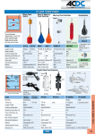
1
METAL DETECTOR METAL SHARK® COMBI Manual (English) Software 3.90c1 TECT-COMBI_service manual with FP.doc METAL SHARK COMBI 1. System Information Customer Name: Location: Date in Service d/m/y: We would like to take this opportunity to thank you for purchasing your Metal Detector from Tectronix. The confidence you have placed in our product is sincerely appreciated and we will endeavour to provide the best service and support possible. Please take the time to read the User Manual completely as this provides you with the expertise necessary to install and adjust the system according to your requirements. In addition to this, you will learn about the sophisticated options provided by the METAL SHARK electronics. If you have any problems in the set up and operation of your system, the Tectronix team are available to assist you. Tectronix Systems inc. Unit 9 18812 - 96th Ave Surrey , British Columbia Canada, V4N 3R1 Equipment Information Label Telephone: (001) 604 607-6028 Fax: (001) 604 607-6026 E-mail: [email protected] 1-2 METAL SHARK COMBI 2. Installation Do’s and Don’ts Electrical - Do Not cut the sensor head cables These cables are equipped with special double shields and connectors and must not be cut. The cable supplied with your metal detector has been used to tune the sensor head and must be the only cable used to connect the sensor head to the electronics. It is therefore recommended that consideration be given to where the connection boxes are located and that all cables be installed in conduit. - Do Not weld in reasonable proximity to the metal detector Welding in the vicinity of the metal detector may cause false metal alarms due to the spectrum of frequencies that welding induces into the environment/ground. Turn detector power off before welding near the detector. - When welding, do not use the control panel mounting surface as a ground - Install a UPS (uninterruptible power supply) to supply clean power and a filtered ground. Voltage fluctuations and changing ground potentials can cause false tripping therefore a UPS with a filtered ground is highly recommended. - Do Not install the metal detector near MCC's or control panels Stray electromagnetic fields can trigger false trips. - Run the connector cables to the metal detector separately Connector cables are part of the metal detector and have to be protected against noise. It is highly recommended to run them in a dedicated conduit. The conduit should be metal but, must be grounded. If the conduit is to be connected at the transmit/receive boxes on the coil and/or the control panel, all fittings must be plastic. - Do Not install the detection coil inside an electromagnetic field (strong power supply fluctuations) Interferences can trigger faults. For example; Where units are installed in close proximity to chipper motors, when under high amperage draw, can cause nuisance or false tripping and this may require the fabrication of a shield. - Do Not disconnect the metal detector from the power supply main A constant, uninterrupted power supply enables more sensitive adjustments. Powering the unit on and off causes it to recalibrate during which time metal will not be detected. Mechanical - Do Not use conductive ( Anti-Static) belt material. Use of 4 ply “Log Handler” style with a “slider back” Non-conductive belt material is mandatory. When splicing belts use a "Finger over Finger" splice for best results. Ensure all surfaces are clean and free of metal debris at the splice. - Vibration-less installation of the detector coil (except "VT") Higher sensitivities can be attained and maintained if the operating conditions are optimal. Ensure the coil is mounted to a structure that is stationery at all times. - Eliminate loose metal to metal connections near or within the detection field Intermittent metal to metal contacts from such things as roller axis, loose bolted connections, or broken welds can cause the metal detector to false trip especially on the higher sensitivity settings. - Vibration less installation of the Control Panel Mount the control panel on a vibration free surface. Vibration can cause premature electronic component failure. - Avoid cable whiplash………. On "VT" Vibratory Conveyor installations, use the supplied cable clamps and tie wraps to secure the cables to the metal detector housing. Doing so will avoid whip lash at the transmit/receive box strain relief connections. In addition to this we recommend that you loop the cables as they exit the conduit. These loops will then flex as the conveyor cycles. It is also advisable to follow this procedure on belt conveyor installations. - Do Not touch the sensor/coil surface of the detector Mechanical contacts may cause detection errors. Keep the sensing surface free of debris. - Mount the FLAT PLATE type coils as close as possible to the underside of the vibrating conveyor or belt conveyor. Do not allow the sensor face to touch the conveyor pan. The closer the coil to the product being conveyed, the greater the sensitivity. Do not allow material to build up on the sensing face so that it touches the conveyor pan. Doing so creates a closed conductive loop and the metal detector will false trip. - Isolate rollers on belt and driven roll conveyors On belt and roller conveyor applications where a roller is less than 24" (610mm) from the centreline of the detector, the roller must be isolated on one side to avoid the possible effect of errant static charges. Use a UHMW shim beneath the bearing and nylon washers or some other non conductive material beneath the bolt head and nut/flat washer. The bolts should also be sleeved with a non conductive material. It may be necessary to isolate more than one roller in either direction to achieve the desired results. 2-3 METAL SHARK COMBI 3. Important To Know IMPORTANT THINGS YOU NEED TO KNOW ABOUT METAL DETECTORS Fiction outweighs fact when it comes to information available about metal detectors. There is an unlimited supply of opinions and assumptions made about metal detectors and how they should operate and perform. You will never get the same opinion from two people on how a metal detector functions let alone how it is expected to perform. The following information is simply stated and designed to educate. Fact: 1. A metal detector can not be selectively programmed to ignore small metal such as dross from drag chains staples or fine particulate and only trip on larger metal that can damage downstream processing equipment. 2. There is no 'plug and play'. All systems will require some adjustment following installation. 3. The closer the metal is to the sensing face, the smaller the size that will make the unit trip. For example; A grouping of small ferrous metal particles the size of pin heads can register the same signature as a 3/8" diameter x 3" long bolt! Installing a system prior to the metal detector to capture the smaller ferrous tramp metal is a good idea. 4. A metal detector must be installed in an environment that is as stable as possible avoiding such things as proximity to high voltage lines and or MCC panels or large electric motors. 5. Power supply and ground are critical. Older, analogue systems require a constant voltage power supply while the newer micro processor systems require a filtered UPS to supply clean power. 6. Depending on the angle metal is presented to the sensing face will in part dictate the sensitivity or the ability of the unit to 'see' the metal. For example, a piece of ¼" thick, mild steel that is 6" long x 3" wide produces a very large signature however, if this piece is on end so that only the narrowest point is presented to the sensing face, there is a likelihood it will not be detected. Of course this is dependent on two very important factors; Distance from the sensing face and the sensitivity setting of the metal detector. 7. False/Nuisance tripping can be controlled if not virtually eliminated especially on the newer systems. Simply stated, a metal detector is an antenna and an antenna will sense both mechanical and electrical noise (Ref. Item 3). 8. Follow the installation, operational and maintenance directions/instructions of the manufacturer to the letter. 3-4 METAL SHARK COMBI 4. Table of contents 1. SYSTEM INFORMATION..................................................................................................................1-1 2. INSTALLATION DO’S AND DON’TS ...............................................................................................2-3 3. IMPORTANT TO KNOW ...................................................................................................................3-4 4. TABLE OF CONTENTS......................................................................................................................4-5 5. GENERAL INFORMATION...............................................................................................................5-8 5.1. 6. HINTS FOR USING THIS MANUAL ......................................................................................................5-8 DECLARATIONS ................................................................................................................................6-9 6.1. 6.2. 7. CE - DECLARATION OF CONFORMITY ................................................................................................6-9 MANUFACTURER’S DECLARATION .................................................................................................6-10 SCOPE OF APPLICATION AND QUALIFICATION.....................................................................7-11 7.1. 7.2. 7.3. 7.4. 7.5. 8. NORMAL USE .................................................................................................................................7-11 MISUSE .........................................................................................................................................7-11 REQUIREMENTS FOR OPERATING STAFF ..........................................................................................7-11 OWNER 'S OBLIGATION TO EXERCISE DUE CARE................................................................................7-12 REQUIREMENTS FOR SERVICE AND MAINTENANCE STAFF .................................................................7-12 GENERAL SAFETY INSTRUCTIONS ............................................................................................8-13 8.1. BASIC SAFETY MEASURES ..............................................................................................................8-13 8.2. SAFETY INSTRUCTIONS ABOUT THE METAL DETECTOR .....................................................................8-14 8.2.1. Installation instructions.........................................................................................................8-14 8.2.2. Connecting instructions.........................................................................................................8-14 8.2.3. Instructions about operation..................................................................................................8-15 8.2.4. Protection against interference ..............................................................................................8-15 9. TECHNICAL DESCRIPTION ..........................................................................................................9-16 9.1. 9.2. 9.3. 9.4. 9.5. 9.6. 10. 10.1. 10.2. 11. 11.1. 11.2. 11.3. 11.4. 11.5. 11.6. 12. TECHNICAL DATA ..........................................................................................................................9-16 METAL DETECTOR SHARK® COMBI ............................................................................................9-17 CONTROL UNIT ..............................................................................................................................9-18 SYSTEM OVERVIEW........................................................................................................................9-20 METHOD OF OPERATION .................................................................................................................9-21 OPERATING LIMITS ........................................................................................................................9-22 TRANSPORT ...............................................................................................................................10-23 SAFETY INSTRUCTIONS FOR TRANSPORT AND INSTALLATION ..................................................... 10-23 TRANSPORTING........................................................................................................................ 10-24 INSTALLATION INSTRUCTIONS ............................................................................................11-25 METAL-FREE ZONE .................................................................................................................. 11-25 VIBRATION .............................................................................................................................. 11-25 FEED OF MATERIAL OVER THE SENSOR ...................................................................................... 11-26 MOUNTING ON CONVEYOR / FRAME .......................................................................................... 11-27 KEEP CONVEYOR BELT CLEAN .................................................................................................. 11-27 INSTALLATION OF SENSOR HEAD ............................................................................................... 11-27 OPERATING INSTRUCTIONS ..................................................................................................12-28 12.1. MASTER KEYBOARD ................................................................................................................ 12-28 12.2. STRUCTURE OF THE MENU ....................................................................................................... 12-29 12.3. PRODUCT EFFECT COMPENSATION : BACKGROUND INFORMATION .............................................. 12-30 12.4. STARTING UP ........................................................................................................................... 12-31 12.4.1. Power On............................................................................................................................12-31 12.4.2. Set product speed ................................................................................................................12-31 12.4.3. Teach product effects...........................................................................................................12-32 4-5 METAL SHARK COMBI 12.4.4. Optimize product effect compensation ..................................................................................12-34 12.4.5. Check metal sensitivity.........................................................................................................12-35 12.5. ENTER PRODUCT NAME.............................................................................................................12-36 12.6. PASSWORD FEATURE ................................................................................................................12-37 12.6.1. Enable password feature......................................................................................................12-37 12.6.2. Set new password ................................................................................................................12-38 12.6.3. Enable parameter pass protection........................................................................................12-39 12.7. SET DATE AND TIME .................................................................................................................12-40 12.8. DISPLAY / PRINT A REPORT .......................................................................................................12-41 13. METAL DETECTOR – FUNCTIONS IN DETAIL ....................................................................13-42 13.1. MAIN MENU .............................................................................................................................13-42 13.1.1. Main Screen: Product and signal .........................................................................................13-42 13.1.2. Teach product – teach product effect....................................................................................13-42 13.1.3. Product tolerance ................................................................................................................13-43 13.1.4. Metal Sense mV ...................................................................................................................13-43 13.1.5. Info next PV test ..................................................................................................................13-43 13.1.6. OPEN MENU......................................................................................................................13-44 13.1.7. Password.............................................................................................................................13-44 13.2. REPORT MENU..........................................................................................................................13-45 13.2.1. Metal counter ......................................................................................................................13-45 13.2.2. Info Last metal.....................................................................................................................13-45 13.2.3. Info Product ........................................................................................................................13-46 13.2.4. Info Software Version ..........................................................................................................13-46 13.2.5. Print....................................................................................................................................13-46 13.2.6. Interface..............................................................................................................................13-47 13.2.7. BAUD .................................................................................................................................13-47 13.2.8. SHARKNET / Unit # ............................................................................................................13-47 13.2.9. Report to printer..................................................................................................................13-47 13.2.10. Report to LCD .................................................................................................................13-48 13.2.11. Exit Report Menu.............................................................................................................13-48 13.3. PRODUCT MENU ......................................................................................................................13-49 13.3.1. Name...................................................................................................................................13-49 13.3.2. Product is ... ........................................................................................................................13-50 13.3.3. PRODUCT X TOL...............................................................................................................13-50 13.3.4. PRODUCT Y TOL ...............................................................................................................13-51 13.3.5. Teach Area ..........................................................................................................................13-51 13.3.6. Amplification X%.................................................................................................................13-51 13.3.7. Amplification Y%.................................................................................................................13-52 13.3.8. Phase ..................................................................................................................................13-52 13.3.9. Phase track..........................................................................................................................13-52 13.3.10. METAL ALARM...............................................................................................................13-53 13.3.11. Copy Product...................................................................................................................13-53 13.3.12. Exit Product Menu...........................................................................................................13-53 13.4. TEACH MENU ........................................................................................................................13-54 13.4.1. Sense min mV ......................................................................................................................13-54 13.4.2. Teach min count ..................................................................................................................13-54 13.4.3. Teach max count..................................................................................................................13-55 13.4.4. Teach time...........................................................................................................................13-55 13.4.5. STATISTIC sec ....................................................................................................................13-55 13.4.6. Teach enable .......................................................................................................................13-56 13.4.7. Teach reject .........................................................................................................................13-56 13.4.8. Exit Teach Menu..................................................................................................................13-56 13.5. VALIDATION MENU ..................................................................................................................13-57 13.5.1. Reject Confirm.....................................................................................................................13-57 13.5.2. Bin Full ...............................................................................................................................13-57 13.5.3. Low Air ...............................................................................................................................13-57 13.5.4. Performance Validation Menu .............................................................................................13-58 13.5.5. Exit Validation Menu...........................................................................................................13-60 13.6. SYSTEM MENU .........................................................................................................................13-61 13.6.1. SPEED ................................................................................................................................13-61 13.6.2. Remote product ...................................................................................................................13-61 13.6.3. Password.............................................................................................................................13-62 4-6 METAL SHARK COMBI 13.6.4. REJECT MENU ..................................................................................................................13-62 13.6.5. DATE / TIME MENU ..........................................................................................................13-63 13.6.6. AUTOSPEED MENU ..........................................................................................................13-64 13.6.7. CIP MENU .........................................................................................................................13-66 13.6.8. IN / OUT MENU .................................................................................................................13-67 13.6.9. FILTER SUBMENU ............................................................................................................13-70 13.6.10. SENSOR CALIBRATION .................................................................................................13-72 13.7. EXIT MENU ............................................................................................................................. 13-74 14. ELECTRICAL CONNECTIONS ................................................................................................14-75 14.1. CONNECT POWER SUPPLY ......................................................................................................... 14-75 14.2. CONTROL SIGNALS ................................................................................................................... 14-76 14.3. MASTER AND SLAVE PCB BOARD TERMINALS .......................................................................... 14-77 14.3.1. Terminals at power supply board.........................................................................................14-77 14.3.2. Relays K1, K2 function ........................................................................................................14-77 14.3.3. Terminals at mainboard ......................................................................................................14-78 14.3.4. PCB Boards Terminals / Electrical wiring and functions......................................................14-79 15. 15.1. 15.2. 15.3. MAINTENANCE AND REGULAR INSPECTIONS ..................................................................15-81 MAINTENANCE ........................................................................................................................ 15-81 REGULAR INSPECTIONS ............................................................................................................ 15-81 NOTES ..................................................................................................................................... 15-81 16. ERROR MESSAGE OF THE SOFTWARE................................................................................16-82 17. INSTRUCTION SHEET ..............................................................................................................17-84 17.1. 17.2. 17.3. 18. GENERAL FUNCTION ................................................................................................................ 17-84 GENERAL METAL DETECTOR MANUAL....................................................................................... 17-85 EXAMPLE: DAILY METAL DETECTOR RECORD .......................................................................... 17-85 PARAMETER LIST SHARK® METAL DETECTOR / SOFTWARE 3.____ ..........................18-86 4-7 METAL SHARK COMBI 5. General Information 5.1. Hints for using this Manual ® Model: METAL SHARK COMBI Manufacturer: Tectronix Systems Inc 9 – 18812 96th Ave Surrey BC Canada Print Date of this Manual: V4N 3R1 April 2008 ® This manual contains all needed information for operating the Metal SHARK and is directed to the workers and experts. Before operation of this metal detector it is important this manual is read in its entirety. It is important that function and operation is understood. Please pay special attention to the safety notes. At no time is any page to be removed from this manual. If this manual or any pages become lost, you should request a new manual immediately. Note: Tectronix Systems Inc gives no implicit guarantees regarding standard qualities or suitability for a certain application. This documentation contains information which is subject to copyright. No part of it may be photocopied, duplicated, translated or recorded on data media without prior consent from Tectronix Systems Inc. This documentation is subject to change by Tectronix Systems Inc. The manufacturer reserves the right to make changes to this documentation. All rights reserved. 5-8 METAL SHARK COMBI 6. Declarations 6.1. CE - Declaration of conformity The producer: Tectronix Systems Inc 9 – 18812 198th Ave Surrey BC Canada certify herewith the machine: Metal detector type SHARK ® conforms with the protection requirements of Council Directive 89/336/EEC on the approximation of the laws of the Member States relating to electromagnetic compatibility. The machine is produced according to the relevant harmonised European standards: DIN EN 292 DIN EN 60204 - 1 DIN EN 60529 DIN EN 60947-7 DIN EN 60742 DIN EN 61000 EN 50022 EN 50081-2 EN 50082-2 Sicherheit von Maschinen; Grundbegriffe, allgem eine Gestaltungsleitsätze;Technische Leitsätze und Spezifikationen Safety of machinery; basic concepts, general principles for design Sicherheit von Maschinen; Elektrische Ausrüstungen von Maschinen, Allgemeine Anforderungen Safety of machinery - Electrical equipment of machines - General requirements Schutzarten durch Gehäuse (IP Code) Degrees of protection provided by enclosures (IP code) Niederspannungs-Schaltgeräte - Teil 7: Hilfseinrichtungen: Reihenklemmen für Kupferleiter Low-voltage switchgear and controlgear - Part 7: Ancillary equipment, Terminal blocks for copper conductors Trenntransformatoren und Sicherheitstransformatoren Isolating transformers and safety isolating transformers Elektromagnetische Verträglichkeit (EMV) Electromagnetic compatibility (EMC) Industrielle Niederspannungs-Schaltgeräte; Tragschienen, Hutschienen, 35 mm breit, zur Schnappbefestigung von Geräten Low voltage switchgear and controlgear for industrial use; mounting rails, top hat rails, 35 mm wide, for snap-on mounting of equipment Elektromagnetische Verträglichkeit (EMV); Fachgrundnorm Störaussendung; Teil 2: Industriebereich Electromagnetic compatibility (EMC); generic emission standard; part 2: industrial environment Elektromagnetische Verträglichkeit (EMV) - Fachgrundnorm Störfestigkeit - Teil 2: Industriebereich Electromagnetic compatibility (EMC) - Generic Immunity Standard Part 2: Industrial environment Surrey , April 05, 2002 Greg Balmer Tectronix, Managing Director 6-9 METAL SHARK COMBI 6.2. Manufacturer’s Declaration The producer: Tectronix Systems Inc 9 - 18812 198th Ave Surrey BC Canada certifies herewith that the machines ® Metal detector type SHARK are in conformity with the provisions of the following EC Directive(s) when installed in accordance with the installation instructions contained in the product documentation: EG- Machinery Directive 98/37/CE EG-Directive electromagnetic compatibility 89/336/CE Herewith we declare that the described product is intended to be incorporated into machinery and must not be put into service until the machinery into which it is to be incorporated has been declared in conformity with the provisions of the EU-directives 98/37/CE. The equipment complies with: DIN EN 292 Safety of machinery; basic concepts, general principles for design DIN EN 60204 - 1 Safety of machinery - Electrical equipment of machines - General requirements DIN EN 60529 Degrees of protection provided by enclosures (IP code) DIN EN 60947-7 DIN EN 60742 DIN EN 61000 EN 50022 EN 50081-2 EN 50082-2 Low-voltage switchgear and controlgear - Part 7: Ancillary equipment, Terminal blocks for copper conductors Isolating transformers and safety isolating transformers Electromagnetic compatibility (EMC) Low voltage switchgear and controlgear for industrial use; mounting rails, top hat rails, 35 mm wide, for snap-on mounting of equipment Electromagnetic compatibility (EMC); generic emission standard; part 2: industrial environment Electromagnetic compatibility (EMC) - Generic Immunity Standard Part 2: Industrial environment Surrey, 01 March 2007 Greg Balmer Tectronix, Managing Director 6-10 METAL SHARK COMBI 7. Scope of application and qualification 7.1. Normal use ® Metal Detector SHARK series is solely designed for detecting metal foreign bodies in non-metal products. For measurement the products may be in • solid, • liquid or • powder form. 7.2. Misuse ® Metal Detector SHARK series is not designed for uses other than those listed in 7.1 Normal use- otherwise it is regarded as misuse. In particular, we draw attention to the fact that it is not allowed • to change or remove safety devices from the metal detector or the associated peripheral equipment in order to perform measurements other than those indicated in 7.1 Normal use. • to use the machine for a purpose which is not approved. • to convert the machine without consent from Tectronix Systems Inc in order to use it for a different purpose. Please bear in mind that if you perform any conversion work you may be deemed the manufacturer of the metal detector – with all the consequences! 7.3. Requirements for operating staff ® To operate the Metal Detector SHARK series no special knowledge of measuring technology, mechanical engineering or electrical engineering is necessary. However, the operating staff must be at least 18 years of age and, before commencing work for the first time, must have received training from the owner of the machine. After receiving initial training the operating staff must be in a position to perform the following activities without supervision: • Put the metal detector into operation and take it out of operation. • Be acquainted with the functions of the metal detector and be able to carry them out. • Perform regular performance checks and visual inspections on the metal detector. • Inspect the safety devices prior to commencement of work and during operation. • Elimination of minor faults for which no occupational training in the field of mechanical engineering or electrical engineering is required. 7-11 METAL SHARK COMBI 7.4. Owner's obligation to exercise due care ® Metal Detector SHARK series has been designed and built taking due consideration of a hazard analysis and after careful selection of the harmonised standards to be observed, as well as other technical specifications. It is therefore state of the art and guarantees maximum safety. However, in practical operation this safety can only be maintained if all the necessary measures are taken. As part of his obligation to exercise due care, the owner must plan these measures and monitor their implementation The owner of the equipment must, in particular, ensure • that the machine is only subjected to normal use (refer to 7.1 Normal use). • that the machine is only operated if it is in good working order and particularly the safety devices are regularly checked to make sure they are operative. • that the Operating Instructions are always in a legible state and are available in their entirety at the place where the machine is used. • that only adequately qualified and authorised staff operate, service and repair the machine. • that before commencing work for the first time, and also thereafter on a regular basis, these staff receive instruction on all the relevant issues regarding safety at work and environmental protection and that they are acquainted with the Operating Instructions and particularly the safety instructions therein. • that all the safety signs and warnings attached to the machine are not removed and remain legible. 7.5. Requirements for service and maintenance staff To be able to perform maintenance work properly, a period of occupational training in the area of mechanical engineering or electrical engineering must have been successfully completed. Repair work may only be performed by trained maintenance staff. For service and maintenance work on the metal detector knowledge of the German or English language is absolutely essential. After initial training the service and maintenance staff must be in a position to perform the following activities without supervision: • Conduct regular performance checks and visual inspections on the metal detector. • Locate faults and remedy faults. • Regularly inspect the safety devices. • Initial commissioning, maintenance, repair and shutdown of the metal detector. 7-12 METAL SHARK COMBI 8. General safety instructions 8.1. Basic safety measures Danger! • Never put the metal detector into operation without the safety devices provided by the manufacturer. Only specially trained maintenance staff are allowed to operate the equipment without the safety devices. • Shut the machine down immediately if the safety devices are not operating properly. • or if there are other apparent defects which pose a danger. Any defects must be remedied or reported without delay. • Always observe any warning signs attached to the machine. They help prevent dangerous situations. Removal of these warning signs is strictly prohibited. • Never put the metal detector into operation • if you have not received complete initial training from the owner or • if you have not fully read these Operating Instructions or • if you have not fully understood these Operating Instructions. • Operating errors may result in severe injury or damage. • Entering the area of the equipment is strictly prohibited for unauthorised persons. An unauthorised person is a person who has not been instructed to work on the metal detector. • Wear closely fitting working clothes which cannot get caught in rotating parts (e.g. conveyor belt). • Keep the floor at your place of work clean. Remove any oil and obstructions without delay. • Naked flames and smoking are not allowed. Danger! • Never touch any live parts. Electric shocks may lead to severe injury or death. • During servicing or maintenance work always wear insulated safety shoes with thick crepe soles. • Report any damaged cables to the maintenance staff immediately. • Keep all access doors to the electrical equipment locked. 8-13 METAL SHARK COMBI 8.2. Safety instructions about the metal detector Important! ® Smooth and safe operation of Metal Detector SHARK following points are observed. series is only possible if the 8.2.1. Installation instructions • Always attach an earth clamp for welding equipment directly next to the weld. • Never allow the welding current to flow through the housing of the metal detector. This would damage the metal detector beyond repair. 8.2.2. Connecting instructions • Check to make sure the mains voltage is the same as that required for the equipment. • The detector must be fitted and connected up by trained staff only. • Observe general installation regulations for setting up and operating electrical equipment (VDE 0100). • Consequently, never perform any work on the metal detector when it is switched on. • Take precautions to protect human life and the machine in accordance with the local conditions and regulations. • Metal Detector SHARK series is designed for permanent, steady-state installation. • Never connect or disconnect control cables or coaxial cables while the metal detector is switched on. • Never connect mains cables, control cables or coaxial cables incorrectly. • Observe the current-carrying capacity of the output contacts. • Use screened/twisted-wire mains and control cables. Only connect the screening to the earth lead at the metal detector end. • Never lay the mains cable and control cable together in a single cable run. • Make sure the metal detector is properly grounded (neutral earth; avoid ground loops; use the shortest connection to the mains ground). ® 8-14 METAL SHARK COMBI 8.2.3. Instructions about operation ® To prevent Metal Detector SHARK series from ageing prematurely or being damaged beyond repair, please observe the following instructions: • The metal detector should always remain switched on. This will maximise the service life of the electronic circuitry. • Use a Filtered UPS in order to supply clean reliable power to the detector • Only operate the metal detector under suitable conditions (refer to Normal use). 8.2.4. Protection against interference The mains input of the metal detector is protected against interference. A high level of operational reliability and additional protection against malfunctions is achieved by the following measures: • Use of mains filters if the mains voltage is affected by the switching-on of heavy-load appliances (compensation systems, welding equipment, HF furnaces, solenoid valves, etc.). • Providing suppresser circuits for inductance appliances (solenoid valves, contactors, electromagnets) using RC elements (Resistor/Capacitor elements) in order to absorb the energy being released by switching off. • Use a Filtered UPS in order to supply clean reliable power to the detector 8-15 METAL SHARK COMBI 9. Technical description This section tells you about the design of your metal detector and how it operates. We are sure that the information will help you to use the metal detector to full advantage. 9.1. Technical data Power supply Power consumption Product speed Ambient temperature Protective type Sensor link cables Measuring Electronics User interface Out signals Features 85-264 V / 50-60 Hz ± 10% 1kW + 0,1kW * number of segments 20 – 300 m/min, other speeds on request -10...+50 C / 15...120 F Sensor IP65 / Control cabinet IP54 10 m (4.1 ft), with conduit Balanced pair of inductive coils Multi-channel-technology Latest digital technology Digital dynamic noise filter Digital balance control Digital frequency control Self-monitoring of function No maintenance required Self-adjusting of all circuits Power Drive circuit Keyboard and LC-display Intuitive, self-explaining menus LEDs bar meter (metal signal) LEDs for OK / Fault / Metal Programmable function keys Password protection Product library for 120 set-ups Product teach manager Timer for reject device control History feature (data logging) General metal alarm (dry contact) General error alarm (dry contact) Segment metal alarm (dry contact for each segment) Flash light (general metal alarm) Horn (general metal alarm) Segment metal alarm (red lamp per segment) Run indicator (green lamp) Error indicator (red lamp) Reset metal alarm push button (internal + remote) Local 24V DC (2.5 Amps) power supply (Siemens brand) Cabinet cooling fan Automatic circuit breaker 16A Over voltage surge protection 230V AC Mains filter (electromagnetic interference filter) Mains switch UPS uninterruptible power supply Double shielded sensor coax cable Power-on timer for proper boot procedure Electric equipment = Klöckner Moeller brand Cabinet = Rittal brand, grey RAL 7035 9-16 METAL SHARK COMBI 9.2. Metal Detector SHARK® COMBI ® Metal Detector SHARK COMBI consists of two assemblies: • • A sensor head for attaching to conveyor belts, webs or textile materials Control unit for operating, controlling and signal processing. 9-17 METAL SHARK COMBI • 9.3. Control unit The control unit comprises • controls, • electrical connections and • signal evaluation system 1) LC display MASTER Displays all functions, parameters and system parameters. Function values are transmitted automatically to all slave units via a network. The texts and messages displayed can be grouped into 4 categories: • status display • info displays • function parameters • system parameters All the displays and messages are shown in plain text. 9-18 METAL SHARK COMBI 2) LC display SLAVE Displays all functions, parameters and system parameters just for data transmission control purposes. Function values are transmitted automatically to all slave units. Displays also mV and PHASE values of each single sensor head. 3) Buttons on the control unit You can perform all operating procedures and make all entries using the four buttons on the front panel of the control unit. ⇧ and ⇩: Press one of the two buttons to select one of the possible functions of the metal detector. ⇧: Scroll forwards ⇩: Scroll backwards + and -: Press one of the buttons to change the value of the function currently selected. + : Increase value - : Reduce value 4) Output relay for metal signals and fault messages 5) "RESET" button Press the "RESET" button to reset current metal signals. Metal signals are indicated by a visual or audible indicator (optional). Only reset the metal signal when you have removed the product containing metal or the metal part. 9-19 METAL SHARK COMBI 9.4. System overview The metal detector is constructed as a multi-segment-sensor. The total inspection-field of the detector is thus divided into several single zones, each of them being about 300 mm wide. This makes it possible to assign detected metal particles to a definite area of the textile width. Neighbour segments overlap each other to have the full sensitivity even at the segment edges. Each sensor segment consists of a balanced pair of inductive coils and a slave control unit. Parameter setup is done at the Master control unit only. All parameters are transmitted to the Slave control units through the integrated RS485 digital network. This ensures that all sensor segments are always configured with the same metal sensitivity. 9-20 METAL SHARK COMBI 9.5. Method of operation ® Metal Detector SHARK briefly described below. series operates on the principle of inductance measurement, which is The sensor has two coils: • The transmitter coil and • the receiver coil. The pair of coils must first be balanced before measurement commences. This step takes place automatically after switching on and is termed "adjustment". In the transmitter coil a generator is used to create a flow of electric current. This creates an electromagnetic alternating field (magnetic field) in the sensor. If a particle of metal now passes through the metal detector — and hence through the magnetic field — the magnetic field of the transmitter coil is changed. As a result of the change in the magnetic field an electric current is created in the receiver coil. This process is termed "electromagnetic induction". The amount of current generated (induced) is directly proportional to the magnetic and electrical properties of the particle of metal: • Large metal particles induce a higher current than small metal particles • Magnetic metals (e.g. steel) induce a higher current than non-magnetic metals (e.g. aluminium) The current thus induced is measured and then processed and analysed by the electronic circuitry. Since this method of measurement responds to • electrical conductivity and • magnetism all types of metal are detected. However, magnetic metals are detected more reliably than nonmagnetic ones. The method of measurement also makes it possible to detect metal particles inside the product or in non-metal packaging. The products examined are not harmed or changed by the measurement in any way. 9-21 METAL SHARK COMBI 9.6. Operating limits Not only metals but also many other materials and raw materials are more or less electrically conductive. The reasons for this can, for example, be • salts, • sugar, • minerals, • moisture or • carbons in the materials. This means that a current is constantly being induced in the receiver coil although there are no metal particles in the material being examined. This effect is termed "product effect" or "material effect". The product effect has a characteristic value for each material. Since the value is constant within a certain bandwidth, it can be taken into account by the metal detector and compensated for. The level of sensitivity which can be achieved in practice is often dependent on: • How well any product effect can be compensated for by the metal detector. • How carefully the metal detector has been installed (e.g. strong vibrations, moving metal directly next to the sensor, electromagnetic interferences etc.). 9-22 METAL SHARK COMBI 10. Transport 10.1. Safety instructions for transport and installation Danger ! To prevent damage to the machine and hazardous injuries when transporting and installing the machine it is absolutely essential that the following instructions are observed: • Transport and installation work may only be performed by qualified personnel observing the safety instructions. • The machine may only be lifted using the frame provided. • To transport the machine only the hoisting and sling gear specified here may be used. • When selecting suitable hoisting equipment always take the following weights into account: • depending on size and type, the metal detector can weigh up to 1,000 kg • The transport route must always be guarded by a third person. • The transport routes must be cordoned off and guarded so that no unauthorised persons may enter the danger zone. • Any projecting sharp edges may cause injuries due to cuts. • Suspended loads may drop, in which case there is a risk of fatal injury – never remain under suspended loads. • Live ends of electric cables and components may cause injury due to electric shock. • Parts lying unsecured on top of one another may slip and drop. • During welding there is a risk of fire. • Cables which have not been laid properly (e.g. radius of curvature too small) may cause smouldering fires and cable fires • Also read the section General Safety Instructions. 10-23 METAL SHARK COMBI 10.2. Transporting Choosing suitable hoisting equipment. When choosing hoisting equipment always use padded cables or straps. Using of chains could lead to damaging of the metal detector. Danger ! Never lift the entire set of equipment directly at the sensor head. The heavy weight of the entire set of equipment may cause damage to the sensor head. 10-24 METAL SHARK COMBI 11. Installation instructions The following points require special attention during installation: • Metal-free zone • Vibration • Feed of belt through sensor • Mounting on conveyor / frame • Keep conveyor belt clean • Welding of transversal struts and contact points • Installation of sensor head 11.1. Metal-free zone A metal-free zone of 500 mm is required in front of and behind the sensor heads. Sensor 500 mm 500 mm 11.2. Vibration • Install the metal detector so that it is exposed to as little vibration as possible in operation. • Light vibrations do not affect the detector. • The metal alarm can be triggered by a hard shock. 11-25 METAL SHARK COMBI 11.3. Feed of material over the sensor • The material shall be moved over the sensor with a gap of 0 to 1 mm. The material shall touch the detectors anti-static sensor surface. • The sensor must align with the material as close as possible. Make sure that all sensors touch the material. 11-26 METAL SHARK COMBI 11.4. Mounting on conveyor / frame • Ensure even and stable contact between detector and mounting bracket. • The metal detector must not be subjected to any mechanical stress or tension during the installation and during tightening of the mounting bolts. 11.5. Keep conveyor belt clean In case of installation with a conveyor belt: The transport belt must be kept absolutely clean. Even small metal particles and contamination could trigger a metal alarm on cycle of the transport belt. The conveyor must be cleaned of metal fines and dust before installation. Do not unpack the belt until immediately before installation. • Do not walk on the conveyor belt without clean protective shoe covers or other protective measures. Visible or invisible shoe prints may contain metal particles. • Ensure that the belt is well-covered, e.g. with cardboard, before welding or grinding. Hot welding slag or grinding sparks can embed themselves in the surface of the belt. 11.6. Installation of sensor head Important! The sensor head must not be subjected to any mechanical stress or tension during the installation and during tightening of the mounting bolts. Caution! Always attach the grounding clamp of the welding unit directly next to the welding spot. Do not allow welding current to flow through the case of the metal detector under any circumstances. This will lead to the destruction of the detector! 11-27 METAL SHARK COMBI 12. Operating instructions 12.1. Master Keyboard The function which has just been selected is shown in the LCD display. If a key is held down the value changes rapidly until the key is released. 12-28 METAL SHARK COMBI 12.2. Structure of the Menu The keys Press on). , and are used to navigate through the user interface. several times to return to the main screen (the main screen is displayed after switch- pressed in the main screen, the TEACH PRODUCT - assistant is accessed, as well as With the important product related entries PRODUCT TOL and METAL SENSE. The TEACH PRODUCT assistant allows for the choice of a characteristic product property. Then it automatically adjusts the signal analysis of the metal detector to the products which are supplied during the teach process. Teaching of products is described in detail in the next sections, “Product effect compensation” and “Starting up”. The last item to be accessed with is OPEN MENU. Press to access all other items of the user interface, which are organized in the following menus and sub-menus. Choose the menu of interest using the keys . For a complete list of accessible menu-items, see the “List of parameters” at the end of this manual. The individual menu items are explained in chapter “Metal detector – functions in detail”. REPORT MENU: Information, documentation, and communication • • • • • • • The counter for metal alerts (METAL COUNTER) Characteristic data of the last metal alert (INFO LAST METAL) Info on current product-related settings (INFO PRODUCT 0xx) Info on the next performance validation (if activated) and the software version. Settings for the print-out and data logging of metal alarms and related data (PRINT). Settings to integrate many units into a network, or communicate with a PC (INTERFACE, BAUD, SHARKNET UNIT #). A list of the latest 50 metal alerts, providing signal magnitudes and time of alert, which can be printed (REPORT TO PRINTER) or viewed in the display (REPORT TO LCD). PRODUCT MENU: Settings which are specific to an individual product • • • • The taught product can be NAMEd in alphanumeric format to be easily memorized. Settings as obtained after TEACH PRODUCT (PRODUCT IS, AMP X %, AMP Y %, PRODUCT X TOL, PRODUCT Y TOL, PHASE, PHASE TRACK) Automatic PHASE TRACKing for products with continuously changing properties Transfer of settings to other product number (COPY PROD.) TEACH MENU: General settings to control the TEACH PRODUCT – assistant • • • • A minimum value of METAL SENSE which can be set by TEACH PRODUCT (SENSE MIN). Settings for the duration and minimum product count during TEACH PRODUCT Lock / unlock product number to 0 (no product teach possible – TEACH ENABLE NO) Reject – behaviour during TEACH PRODUCT VALIDATION MENU: Supervision of proper operation • • Supervision of automatic reject devices (REJECT CONFIRM, BIN FULL, LOW AIR) The PERFORMANCE VALIDATION SYSTEM submenu to enforce periodical tests of the metal sensitivity SYSTEM MENU: general configuration of the metal detector (several submenus) • • • • • • • • Product SPEED, PASSWORD protection and REMOTE PRODUCT-number control. Date and time (YY/MM/DD, HH:MM:SS) Setup of the control signal to the reject device (DELAY, DURATION, METAL CONTACT) Automatic belt-SPEED calibration of conveyors driven from frequency inverters Clean In Place switching of the reject device for SHARK-Inline-Models Setup of the Input and Output control lines (24Vdc switching) Choice and setup of digital filters (NOISE LEVEL, FFT FILTER, FIR FILTER, GF MODE) Individual factory settings for the delivered sensor head, which must not be changed by the user (FACTORY SETUP). 12-29 METAL SHARK COMBI 12.3. Product effect compensation: background information Many conveyed materials, especially in the food industry, generate an effect similar to metal parts when they enter the electromagnetic field. This effect is caused by conductive components in the conveyed material (e.g. salt, sugar) and is called 'product effect'. To enable the metal detector to recognize whether the signal coming from the sensor is caused by the product being monitored or by a metal part, the metal detector must be taught the product effect. The product effect is learned on the basis of product samples which have to be passed through the sensor. The product effect may vary from one product sample to another. The better the samples represent the product, the better the product effect will be learned. Below graphs illustrate the TEACH PRODUCT procedure and related parameters. Y The sensor head delivers a signal with the two components X and Y. Such signals are represented as curves in a plane (see graph). Product effect Product PHASE The ratio of X and Y defines an angle, called PHASE (in degrees). The distance to the zero point is the MAGNITUDE (amount) of the signal (in mV). X Noise level A product passing through the detector causes a signal (Product effect) along a general phase (Product PHASE). Detector noise produces small signals near the zero-point of the graph. In the first steps of the teach procedure, the product phase is subtracted by the signal processor. Product signals therefore have small Y components. Y Product effect x PRODUCTTOL In the STATISTIC step of the teach procedure, the area enclosing all product effect signals (and the noise) is determined. Product effect X The parameter PRODUCT TOL scales this area. A value of PRODUCT TOL which is larger than one tells the metal detector to ignore a larger region around the product effect area. Y Metal parts cause signals with a phase different from that of the products. Metal signal It can therefore be detected even if its magnitude is smaller than that of the product effects. X Metal sense threshold A metal alarm is triggered if the magnitude (amount) of the metal signal exceeds the threshold given by METAL SENSE, which is a circle around the zero piont of the graph. 12-30 METAL SHARK COMBI 12.4. Starting up Steps to put the metal detector into first operation: • Power on • Set product speed • Teach product effects • Check metal sensitivity 12.4.1. Power On Step Operation 1. Were the assembly steps followed See “Electric connection” correctly? Is the electrical connected correctly? Were safety regulations kept? Are all cables intact? Check installation 2. Power On 3. Main screen Screen If the installation is ok, switch power supply on. The metal detector runs an internal auto calibration (ADJUST) and then displays the main screen. ADJUST -2048 2047 The metal detector is now in operation. The main screen informs about actual product number, signal amplitude (mV) and signal phase (°). PRODUCT 000 NEUTRAL 3mV 0.00° PRODUCT 000 NEUTRAL 3mV 0.00° Set PRODUCT 000 with Confirm with %100 %100 . . 12.4.2. Set product speed 1. Press to return to main screen. Return to main menu 2. Press OPEN MENU (ESC) HOME . OPEN MENU Press 3. Go SYSTEM MENU Press displayed. Press 4. Set Speed to Open Menu. until SYSTEM MENU is SYSTEM MENU (ESC) HOME (OK) OPEN to Open Menu. Enter product speed using the keys. Press (OK) OPEN SPEED mm/sec 550 (ESC) HOME (-)(+) SET to confirm. Set the actual speed at which material is passed over the sensor heads. 12-31 METAL SHARK COMBI 12.4.3. Teach product effects See “Product effect compensation : background information” (above) for illustrations of the parameters used here. The SHARK COMBI usually does not need any teach, since the materials are none conductive. With SHARK COMBI first try to use PRODUCT 000 and skip these “teach product effects” instructions. With a SHARK COMBI model jump next to “Check metal sensitivity”. Item 1. Operation Press Screen , to return to main menu. Return to main menu 2. Set PRODUCT 1 with Choose product confirm. . Press to PRODUCT 000 NEUTRAL 3mV 0.00° PRODUCT 001 NO NAME 3mV 0.00° Note: Teaching product effects is possible with product 1-120, but not with product 0. 3. Enter TEACH PRODUCT Press until TEACH PRODUCT is displayed. Press to start teach procedure. TEACH PRODUCT (ESC)HOME (OK)START 4. Select now with the product property Choose product which fits best your product or application: property DRY: Products with low humidity, e.g. powder and bulk materials. DRY is recommended for SHARK COMBI PRODUCT IS DRY (+)(-)SET (OK)NEXT WET: Products with water content, but not too much spices, e.g. sausages, meat, fruits, vegetables. SALTY: Products with high amount of salt or high electrical conductivity, e.g. cheese blocks, bloody raw meat. FROZEN: Deep frozen products (-18°C/0°F) ALU FOIL: Products packed in alu vaporized foil PLASTIC: Plastic granulates with graphite VIBRATION: Vibration signals SHOCK: Shock-like action on detector DEFAULT: Uses no product tolerances. Confirm your selection with 5. Run products . Start running products over the sensor (e.g. start the conveyor). Confirm with that product is now running. (Continued on next page) 12-32 RUN PRODUCT LINE (ESC)HOME (OK)NEXT METAL SHARK COMBI 6. The following steps STEP1 – STEP3 are performed automatically (STEP1 – STEP5 in the Automatic teach case of strong product effects, e.g. meat). procedure IMPORTANT NOTE: While RUN PRODUCT is displayed, pass your product continuously through the sensor. Otherwise the TEACH process may fail. TEACH COUNT: Each STEP needs at least one or more product signals. RUN PRODUCT AMP X 200% 2 STEP1 15 RUN PRODUCT PHASE 5 STEP2 12 3 STEP3 27 TEACH COUNT (product signals) TEACH TIME (countdown) TEACH TIME: You have e.g. 15 seconds time for each single step, in order to lead product samples through the sensor. The time can be changed according to your own desires in the submenu PRODUCT PARAMETER under TEACH TIME, e.g. set a longer TEACH TIME with a slow conveyor belt. AMP X sets the hardware amplification for the product effect measuring chanel. PHASE sets product effect phase. STATISTIC: Frequently the product composition varies somewhat and, consequently, the phase from the product effect also varies. This variation is considered in the STATISTIC STEP. 7. When TEACH END is displayed, the teach procedure has been completed. End of teach procedure The resulting parameters are displayed. They are stored in a non-volatile memory and can be displayed later in the INFORMATION MENU under INFO PRODUCT 00X. Press RUN PRODUCT STATISTIC TEACH END (OK)EXIT X25% Y200% YmV126 to return to the main menu. IMPORTANT NOTE: As long as the function TEACH is set, no metals are detected or signalled ! The metal detector is now set to highly sensitive metal detection at robust product effect compensation. Check the performance resulting from the automatic teach process. If necessary, perform the adjustments described on the next page (“Optimize product effect compensation”). If the result is still not satisfactory: • Choose another product number (e.g. PRODUCT 002) • Repeat teach procedure • o Hint: Use various product samples. o Hint: During TEACH, keep wrist watches, wedding rings, or keys and coins in your pocket at distance to the sensor aperture !! Another PRODUCT IS ... setting may yield better results. PRODUCT IS … can also be changed after performing the TEACH –procedure. Press MENU is displayed. Press Confirm your choice with • to enter product menu. Use to choose a different product property. . Compare sensitivities by toggling between the two product numbers. 12-33 until PRODUCT METAL SHARK COMBI 12.4.4. Optimize product effect compensation After teaching a product, products which are free of metal should not cause metal alerts. However, product properties vary, as well as ambient conditions. Metal alerts due to these variations can be avoided by increasing the value of PRODUCT TOL : 1. Press to return to main screen. Press twice to choose PRODUCT TOL Return to main screen 2. Choose PRODUCT TOL. screen. Press to increase the value. High PRODUCT TOL: Better product effect compensation. Metal sensitivity may be lower. Check metal sensitivity (see below) ! 12-34 PRODUCT 001 NO NAME PRODUCT TOL. (ESC) HOME 3mV 0.00° x1.5 (-)(+) SET METAL SHARK COMBI 12.4.5. Check metal sensitivity The metal sensitivity can be checked either at PRODUCT 000 (without teach) or at any product number PRODUCT 001 – 120 (with teach). 1. Press to return to main screen. Return to main screen 2. Run metal test pieces through detector Run metal test pieces with products through the detector several times. 3. Watch the display: Watch display mV = actual signal magnitude PRODUCT 001 NO NAME 0mV 0.00° PRODUCT 001 NO NAME 0mV 0.00° PRODUCT 001 NO NAME 134 mV 23.68° 0.00° = actual signal phase The mV-value represents the size of metal objects. Write down the maximum value for each metal test piece passing the sensor. Do the specified metal test pieces reliably trigger a metal alert? PRODUCT 001 - 120: If not, return to teach procedure above, or decrease the value of PRODUCT TOL. PRODUCT 000: Adjust METAL SENSE 4. Press until METAL SENSE mV is Adjust METAL displayed. SENSE Is METAL SENSE much smaller than the smallest value obtained from the test pieces? If so, METAL SENSE can be increased up to this smallest test-piece value. This additionally suppresses noise and interference, and allows metal objects of negligible size to pass. Press to increase METAL SENSE. Check Metal sensitivity again (2. Run metal ..., 3. Watch display). High METAL SENSE mV: Small metal pieces are faded-out. Better oppression of interfering signals. Check the metal sensitivity again! 12-35 METAL SENSE mV 35 (ESC)HOME (-)(+)SET METAL SHARK COMBI 12.5. Enter product name Below are instructions for assigning alpha-numeric product names. You can use any combination of 11 characters (including spaces). This feature is available for PRODUCT 1-120. 1. Return main screen 2. Select product # 3. key to return to the main PRODUCT 000 NEUTRAL 3mV 0.00° (or any other Set PRODUCT 001 with product number between 1-120).Confirm with PRODUCT 001 NO NAME 3mV 0.00° Press the to screen. . Press OPEN MENU Press . OPEN MENU (ESC)HOME 4. Press until PRODUCT Go displayed. PRODUCT MENU Press to Open Menu.. 5. (OK)OPEN to Open Menu. MENU is PRODUCT MENU (ESC)HOME (OK)OPEN In the display appears NAME = . NAME Press NAME=_ (+)(-)EDIT to enter a name. (MODE)NEXT 6. Edit NAME An underline cursor will start flashing. This cell is active. NAME= ALU FOIL_ (+)(-)EDIT (MODE)NEXT Press the or key until you find the letter or number you wish as the first letter. This letter will flash. PRODUCT 001 ALU FOIL Press the key to move to the next cell. The selected letter will remain and the cursor will now flash at the next cell. NAME=ALU FOIL (ESC)HOME (OK) EDIT 3mV 0.00° If you wish to place a space between a letter or number you press the selecting an letter or number. key without NAME=ALU FOIL_ (+)(-)EDIT (MODE)NEXT When you have finished naming this product press . The screen will change and show you the NAME you have designated for that product #. NAME=A_ (+)(-)EDIT (MODE)NEXT If you agree press to fetch the main screen. If you want to modify the name follow above item 3. and make your changes. NAME= _ (+)(-)EDIT (MODE)NEXT NAME=A (+)(-)EDIT (MODE)NEXT Hint: If you wish to erase the whole name press at the same time. Now you have changed Product 001 to read ALU FOIL (if that is what you entered). Press the key to change to PRODUCT 002. Follow the same procedure as before to name Product 002. 12-36 METAL SHARK COMBI 12.6. Password feature METAL SHARK metal detectors provide a password-function. By its use, the parameter set-up is protected against unauthorized access. Only the PRODUCT # is left to change. 12.6.1. Enable password feature The password feature is shown in the main menu only when enabled. To enable the password feature: 1. Press the key to return to the main screen. Return to main screen 2. Press . OPEN MENU (ESC)HOME OPEN MENU Press PRODUCT 000 NEUTRAL to Open Menu. 3mV 0.00° (OK)OPEN 3. Press until you see the SYSTEM MENU Go SYSTEM screen. MENU Open SYSTEM MENU with . 4. Press until you see the PASSWORD screen. Go PASSWORD 5. Enable PASSWORD Press 1x with YES. Confirm with 6. Press 3x the to enable PASSWORD functions SYSTEM MENU (ESC)HOME (OK)OPEN PASSWORD (ESC)HOME NO (-)(+)SET PASSWORD (ESC)HOME YES (-)(+)SET . key to return to the main screen. Return to main screen PRODUCT 000 NEUTRAL 3mV 0.00° 7. Press until you see the PASS UNLOCK Go PASS screen. UNLOCK The initial password is 0000. It is strongly recommended to set-up your own new password right now. Refer to next chapter “Set new password”. 12-37 PASS UNLOCK (-+)LOCK (OK)NEW METAL SHARK COMBI 12.6.2. Set new password 1. Return main screen 2. Press the key to return to the main screen. to Press until you see the PASS UNLOCK screen. Go PASS PRODUCT 000 NEUTRAL 3mV 0.00° PASS UNLOCK (-+)LOCK (OK) NEW 3. Press to set a new password. It consists of a Set new four digit number. password Press to set the first digit. PASS UNLOCK (-+)LOCK (OK)NEW PASS NEW2 * 4 * * (-+)LOCK (OK)NEXT to move to the next cell. The selected Press digit will remain and the cursor will now flash at the next cell. Repeat this for all cells to set a 4 digit password. PASS NEW2: Now repeat setting exactly the same 4 digit password for confirmation. PASS NEW2 8 * * * (-+)LOCK (OK)NEXT PASS NEW1 * 4 * * (-+)LOCK (OK)NEXT PASS NEW1 8 * * * (-+)LOCK (OK)NEXT After confirming the last digit the display shows the PASS UNLOCK screen. You have now changed to your own new password. 12-38 PASS NEW1 * * * * (-+)LOCK (OK)NEXT METAL SHARK COMBI 12.6.3. Enable parameter pass protection Password The password feature is available if feature SYSTEM PARAMETER / PASSWORD=YES. PASSWORD (ESC)HOME YES (-)(+)SET Refer to above “Enable password feature”. Parameter pass protection is enabled Enable pass o automatically at each power supply on. protection o automatically if no key pressed for 5 minutes. * * * PASS ENABLED * * * (-+)UNLOCK (OK)NEW manually by pressing at the same time in the PASS UNLOCK screen. PASS UNLOCK (-+)LOCK (OK)NEW Disable Parameter pass protection is disabled (unlocked) pass only manually by entering your 4 digit password with protection or . PASS UNLOCK (-+)LOCK (OK)NEW o To enter the password see “Set new password” The screen changes to PASS UNLOCK once you entered the correct password. 12-39 PASS * * * * (-)(+)SET (OK)NEXT METAL SHARK COMBI 12.7. Set date and time 1. to return to main menu. Press Return to main menu 2. MENU OPEN Press Press . PRODUCT 000 NEUTRAL OPEN MENU (ESC)HOME 3mV 0.00° (OK)OPEN to Open Menu. 3. Press until you see the SYSTEM MENU Go SYSTEM screen. MENU Open SYSTEM MENU with . 4. Go DATE TIME MENU 5. Go YY/MM/DD 6. Set Date Press / until DATE / TIME MENU is displayed. Open submenu with Press . until YY/MM/DD is displayed The date is displayed in the year/month/day format (two digits each). continuously pressed down. The Keep displayed date changes with increasing speed. SYSTEM MENU (ESC)HOME (OK)OPEN DATE / TIME MENU (ESC)HOME (OK)OPEN YY/MM/DD (ESC)HOME 00/00/00 (+)(-)SET YY/MM/DD (ESC)HOME 03/01/23 (+)(-)SET HH:MM:SS (ESC)HOME 00/13/48 (+)(-)SET HH:MM:SS (ESC)HOME 14/28/35 (+)(-)SET Release as soon as the displayed date approaches the actual date (year/month). Set the exact date using 7. Go HH:MM:SS 8. Set Time Press and . until HH:MM:SS is displayed. The time is formatted as hour,:minute,:second (two digits each). continuously pressed down. The Keep displayed time changes with increasing speed. Release as soon as the displayed time approaches the actual time (hour/minute). Set the exact time using and . 12-40 METAL SHARK COMBI 12.8. Display / print a report 1. Press to return to main menu. PRODUCT 000 NEUTRAL Press until OPEN MENU appears. OPEN MENU (ESC)HOME Press to open menu. Return to main menu 2. OPEN MENU 3. Open REPORT MENU 4. METAL COUNTER 5. 3mV 0.00° (OK)OPEN REPORT MENU is displayed. Open menu with REPORT MENU (ESC)HOME (OK)OPEN . The current value of the metal counter is displayed METAL COUNTER 8 (ESC)HOME (+-)RESET Hint: To reset metal counter press simultaneously. Press until PRINT is displayed. Go PRINT Press In the alternative mode ONE BY ONE, metal alerts are printed continuously as soon as they occur. Press PRINT (ESC)HOME REPORT (OK)STORE . In printing mode REPORT, the last 50 metal alerts are sent at once to the protocol printer (optional). Time and signal magnitude of each alert event are printed. Press Print out Report displayed. OFF (OK)STORE to choose printing mode REPORT. Confirm with 6. PRINT (ESC)HOME until REPORT TO PRINTER is REPORT TO PRINTER (ESC)HOME (OK)OPEN to start print-out. Note: The printer is optional equipment. 7. Display Report Alternatively, the REPORT of the metal alerts can be viewed on the display. Press until REPORT TO LCD is displayed. Press to display the last metal alert. Use and alert entries. METAL mV 03/01/23 675 #7 15:33:48 REPORT TO LCD (ESC)HOME (OK)OPEN to navigate through all metal METAL mV 03/01/23 12-41 586 #6 14:05:23 METAL SHARK COMBI 13. Metal detector – functions in detail 13.1. Main menu The main menu you always reach by returning to the main screen (pressing There you can choose the several menus by pressing several times). . 13.1.1. Main Screen: Product and signal You can cancel the current data entry and return to the main screen by pressing Selected product effect memory number Actual sensor signal magnitude (amount). PRODUCT 000 NAME Product name entered) • . 3mV 0.00° (when Actual sensor signal phase. The PRODUCT line indicates which product effect is blanked out at the present moment. The keys can be used to set the product memory number. • In the setting “Product 000” product effects can not be learned and blanked out. • Product effects can be taught using the Teach Product assistant for the product memories 1 – 120. • When the product effect is blanked out value and phase are only displayed when there is a metal notification. IMPORTANT: Set always PRODUCT 000 as long as you have not taught any product effects or if you are not sure what is stored in the product memories 1...120. If this rule is not observed, even large metals may not be indicated. 13.1.2. Teach product – teach product effect TEACH PRODUCT 001 (ESC)HOME (OK)START TEACH PRODUCT assistant – This screen starts the teaching process necessary to learn the product properties. Product effect is learned and compensated for. Product memories 1 to 120 can be taught. Product 0 is neutral and cannot be taught. 13-42 METAL SHARK COMBI 13.1.3. Product tolerance PRODUCT TOL (+)(-)SET x 1.3 (ESC)HOME This parameter scales the product effect area. Metal alerts due to variations in product effect can be suppressed by increasing PRODUCT TOL. The initial setting depends on the chosen product property (PRODUCT == …). See “Product compensation: Background information” and “Teach product effects” for details. 13.1.4. Metal Sense mV METAL SENSE mV 50 (+)(-)SET (ESC)HOME This function allows the operator to specify the minimum signal amplitude of metal parts which have to be signalled. The mV value can be adjusted in the range from 3 to 3000 by means of the keys. With METAL SENSE mV 3 the smallest detectable metal parts are signalled. The sensitivity decreases linearly with increasing value of METAL SENSE. At 3000 mV only very large metal parts are signalled. To determine which magnitude a particular metal part generates, refer to “INFO LAST METAL”. Bear in mind that non-spherical metal parts may generate different magnitudes depending on their orientation. Magnetic metal parts produce a larger signal than non-magnetic metal parts. IMPORTANT: By default the METAL SENSE is set by the product memory and must be set separately for each product memory, if you work with different product memories 1...120 (mainly used in food-industries). 13.1.5. Info next PV test 03/08/27 17:52:06 INFO NEXT PV TEST Default: Not visible Date and time of the next performance validation are displayed. This screen is only visible if the performance validation system is activated. See PVS MENU in the chapter VALIDATION MENU below. 13-43 METAL SHARK COMBI 13.1.6. OPEN MENU OPEN MENU (ESC)HOME Press (OK)OPEN to access the advanced parameter menus described below. 13.1.7. Password PASSWORD XXXX (+)(-)SET (OK)NEXT Default: Not visible. Enter password to make settings. To switch option PASSWORD on/off, go to submenu SYSTEM MENU. Set SYSTEM PARAMETER / PASSWORD = YES. This screen is only visible if password protection is activated. See section “Password Feature” of chapter “Operating Instructions” for a step-by-step introduction. 13-44 METAL SHARK COMBI 13.2. Report menu The REPORT MENU provides • information on metal alerts • information on the current product parameters and • settings to control data logging, print –out and network integration. REPORT MENU (ESC)HOME (OK)OPEN Press to open the REPORT MENU. Press at any time to abort your current data entry and return to main menu. 13.2.1. Metal counter METAL COUNTER 0 (+)(-)SET (ESC)HOME Each metal signal increments the day counter. If the keys are pressed down simultaneously for approx. 2 seconds the counter is reset to zero. This also resets the report memory (see below). 13.2.2. Info Last metal Here the strength of the most recent metal signal of the detector coil is displayed. This value remains on display until the next metal object passes through the detector. AMOUNT: Signal strength or magnitude, indicates the quantity of a metal or product effect. MET PHASE: Type and form of signal (-90° to +90° range), indicates which kind of metal or product. 57 mV PH 28.57° INFO LAST METAL Non-spherical metal objects result in a variety of values dependent upon their length. Magnetic metals produce a stronger signal than non-magnetic metals. Signals are stronger at the edges of the opening than in its centre. Long metal objects may result in the issue of several signals. The 'INFO LAST METAL' display allows product samples to be selected for the teaching process which are as representative as possible. Each product or each material generates a particular phase. The larger the quantity of this material which passes simultaneously through the sensor, the larger the Amount becomes. Frequently the product composition varies somewhat and, consequently, the phase from the product effect also varies. This variation is also learned if correspondingly varying products are included in the teaching process. It must be ensured that the product samples for the teaching process do not contain any metal pieces, as otherwise the metal part will be learned together with the product. 13-45 METAL SHARK COMBI 13.2.3. Info Product AMP X %100 AMP Y %100 INFO PRODUCT 001 Information on current product-related parameters is displayed. The displayed content changes every few seconds (values are examples): NO NAME Name of product memory (NO NAME if no name is assigned) PRODUCT IS DEFAULT Current product property setting TOL x1.5 Current PRODUCT TOL and METAL SENSE values METAL 20mV AMP X%100 AMP Y%100 Signal amplification X and Y PHASE Product phase 0.00° TEACH AREA 1996 20 Size of product tolerances) effect area after teach (neglecting 13.2.4. Info Software Version SHARK BD3.32a-E INFO SOFTWARE VERS. Displays the full name of the software in use. 13.2.5. Print PRINT (ESC)HOME OFF (OK)STORE Default setting: OFF Protocol mode for optional printer. Possible settings are: PRINT OFF: No output to printer PRINT ONE BY ONE: Each metal alert immediately causes a printed message containing date, time, the signal magnitude (as displayed in INFO: LAST METAL) and the value of METAL COUNTER. PRINT REPORT: A report of metal alerts is printed on demand, containing up to 50 metal alerts since the last reset of the METAL COUNTER. If more than 50 metal alerts occurred, the latest 50 are reported. Print-out is started by REPORT TO PRINTER (see below). PRINT SERVICE enables you to transfer the current raw data on a connected laptop. PRINT SHARKNET: All protocol data is transmitted to an external PC via serial port. 13-46 METAL SHARK COMBI 13.2.6. Interface INTERFACE (+)(-)SET RS232 (ESC)HOME Default value: RS232 Choose the same interface for all instruments that are communicating with SHARKNET. RS232 standard serial interface RS485 serial interface, symmetrical data transmission for improved reliability ETHERNET with optional Com-Server 13.2.7. BAUD BAUD (+)(-)SET 9600 (ESC)HOME Default: 9600 Set data transfer rate of the interface for all instruments that are communicating with SHARKNET: Possible values: 9600 / 14400 / 57600 / 115200 / 230400 Baud 13.2.8. SHARKNET / Unit # SHARKNET / UNIT # 0 (+)(-)SET (ESC)HOME Default value: 0 The Unit Number is the identification of each single unit within the Sharknet. The number 0 (zero) automatically sets the unit as the master of a system of detectors. Numbers 1 to XX automatically set the corresponding unit as a slave, which then is remote controlled. For single detector, stand alone operation, set SHARKNET / UNIT # = 0. 13.2.9. Report to printer REPORT TO PRINTER (ESC) HOME (OK) OPEN Press to print out a report of metal alerts in mode PRINT REPORT (see above). The print-out is formatted similar to the entries displayed by REPORT TO LCD (see below). 13-47 METAL SHARK COMBI 13.2.10. Report to LCD REPORT TO LCD (ESC) HOME (OK) OPEN Press to display a report of metal alerts on the LCD screen (same information as REPORT TO PRINTER). The last entry is displayed: METAL mV 148 03/01/27 #4 14:53:24 Use and to navigate through the entries. Press return to INFORMATION MENU to return leave display mode and If METAL COUNTER = 0 (no metal alerts since last counter reset), the display shows: * * If no metal alert occured since switch-on of the detector, the software-version and power-on time are displayed: POWER ON 03/01/27 BD2.012e 07:46:57 13.2.11. Exit Report Menu EXIT MENU (ESC) HOME Push (OK)EXIT to exit the submenu REPORT MENU. 13-48 METAL SHARK COMBI 13.3. Product Menu Important: For every product the parameters of the product menu are set individually. Most parameters in the product menu are set automatically during TEACH PRODUCT. They adapt the control unit to suit the individual product effect conditions, and therefore are specific to each product number. The product parameters may be changed by experienced users. PRODUCT MENU (ESC)HOME (OK)OPEN Press to open the PRODUCT MENU. Press at any time to abort your current data entry and return to main menu. 13.3.1. Name PRODUCT NAME (ESC)HOME (+)(-)SET Enter an alpha-numeric name to memorize assignment of products to product memory entries. Edit current digit with Press and . Choose next digit with and . simultaneously to erase whole name. See “Enter product name” for detailed instructions. PRODUCT NAME is available with product 1…120, not with PRODUCT 000. 13-49 METAL SHARK COMBI 13.3.2. Product is ... PRODUCT IS (ESC)HOME DRY (+)(-)SET Choose a product property which characterizes your actual product. According to this property, product compensation will be adjusted to optimally fit your application (see chapter “Teach product effects”). Here you can change the product property also after finishing TEACH PRODUCT. The result is the same as if TEACH PRODUCT had been performed with the currently set product property. Therefore, different product properties can be tried without repeating TEACH PRODUCT every time. One of the following properties can be chosen: DRY: Products with low humidity, e.g. powder and bulk materials. WET: Products with water content, but not too much spices, e.g. sausages, meat, fruits, vegetables. SALTY: Products with high amount of salt or high electrical conductivity, e.g. cheese blocks, bloody raw meat. FROZEN: Deep frozen products (-18°C/0°F) MELTING: Frozen products in warm environment ALU FOIL: Products packed in alu vaporized foil PLASTIC: Plastic granulates with graphite VIBRATION: Vibration signals SHOCK: Shock-like action on detector DEFAULT: No product-specific adjustments are preset. Adjust PRODUC TOL and related parameters by hand. PRODUCT IS is available with product 1…120, not with PRODUCT 000. 13.3.3. PRODUCT X TOL PRODUCT X TOL (ESC)HOME Setting range: 0,0 .... 9,9 1.0 (+)(-)SET Default: 1.0 Scales the Product effect area along the X-direction. PRODUCT TOL X is multiplied by PRODUCT TOL. Refer to “Product compensation: Background information” (Chapter “Operating instructions”) and “Product tolerance” (in the main menu) for details. PRODUCT X TOL is available with product 1…120, not with PRODUCT 000. 13-50 METAL SHARK COMBI 13.3.4. PRODUCT Y TOL PRODUCT Y TOL (ESC)HOME 1.0 (+)(-)SET Setting range: 0,0 .... 9,9 Default: 1.0 Scales the Product effect area along the Y-direction. PRODUCT TOL Y is multiplied by PRODUCT TOL. Refer to “Product compensation: Background information” (Chapter “Operating instructions”) and “Product tolerance” (in the main menu) for details. PRODUCT Y TOL is available with product 1…120, not with PRODUCT 000. 13.3.5. Teach Area TEACH AREA 1620 INFO PRODUCT 001 74 Information on the current teach area, which is influenced by the above parameters PRODUCT IS, PRODUCT X TOL., and PRODUCT Y TOL. TEACH AREA is available with product 1…120, not with PRODUCT 000. 13.3.6. Amplification X% AMP X% (ESC)HOME 100 (+)(-)SET Default: 100 (only PRODUCT 0) Hardware amplification factor for the product effect (X channel). The larger the product effect is, the smaller the amplification X% has to be adjusted. Possible values are 3%, 6%, 12%, 25%, 50%, 100%, and 200%. 3% corresponds to the smallest hardware amplification. When using product memories 1…120: AMP X% is set automatically during TEACH process in STEP 1 (PRODUCT 1-50) according to the following rule: Very strong product effect amplitude = AMP. FACTOR X% 3 Low product effect amplitude = AMP. FACTOR X% 200 13-51 METAL SHARK COMBI 13.3.7. Amplification Y% AMP Y% (ESC)HOME 100 (+)(-)SET Default: 100 (only PRODUCT 0) Hardware amplification factor for the metal signals (Y channel). The larger the product effect crosstalk is, the smaller the amplification Y% has to be adjusted. Possible values are 3%, 6%, 12%, 25%, 50%, 100%, and 200%. 3% corresponds to the smallest hardware amplification. When using product memories 1…120: AMP Y% is set automatically during TEACH process in STEP 3 (PRODUCT 1-50) according to the following rule: Very strong product effect crosstalk in metal channel = AMP. FACTOR Y% 3 Low product effect crosstalk in metal channel = AMP. FACTOR Y% 200 13.3.8. Phase PHASE (ESC)HOME -179.55° (+)(-)SET Default: 0.00° The setting of the product phase helps to blank out any product effect. PHASE is set automatically during TEACH process. PHASE is available with product 1…120, not with PRODUCT 000. 13.3.9. Phase track PHASE TRACK (ESC)HOME Setting range: 0.00° … 10.00° 0.00° (+)(-)SET Default: 0,00° When working with products 1-120 the product phase determined in the teach process can be adjusted during the operation to compensate slow changes of the products. The product effect phase may change depending on product temperature and composition. The parameter PHASETRACK indicates the increment with that the phase is adjusted: Phase tracking gets stronger as higher this value. E.g. a 0.10° means 0,10 degree tracking with each p roduct or metal signal. PHASE TRACK is available with product 1…120, not with PRODUCT 000. 13-52 METAL SHARK COMBI 13.3.10. METAL ALARM METAL ALARM (ESC)HOME PULSE (+)(-)SET METAL ALARM in the product menu controls the switching behaviour of the metal alarm outputs. The setting is made for every product number individually. This way can for example the pusher be activated when product 001 passes through and when product 002 passes through the conveyor belt can stop and a horn start. This menu item is only activated and visible respectively when in the SYSTEM MENU / REJECT MENU / METALL ALARM = PRODUCT is activated. HOLD: Standard value for belt stop with reset push button. PUSH1: Pusher with photo cell active 0V (synchronized reject signal). PUSH2: Pusher with photo cell active 24V (synchronized reject signal). PUSH3: Pusher without photo cell synchronization PULSE: Metal alarm as a pulse with a set duration “DURATION” (also see main menu) Use e. g. when pneumatic nozzles separate the metal GF1: Drives reject flaps with gravity feed applications. Error = flap in reject - position GF2: Drives reject flaps with gravity feed applications. Error = flap in ok – position INLINE: Security drive of inline reject EX-PWC MESEP: Metal separator model MESEP SE METAL CONTACT is available with product 1…120, not with PRODUCT 000. 13.3.11. Copy Product COPY PROD (ESC)HOME 000 ALL (+)(-)SET Copy all PRODUCT MENU parameters of the current PRODUCT to another PRODUCT or to all Products. WARNING: If parameters are copied to a product which was taught already, all the teach settings of this product will be lost! 13.3.12. Exit Product Menu EXIT MENU (ESC)HOME Press (OK)EXIT to exit the PRODUCT MENU. 13-53 METAL SHARK COMBI 13.4. TEACH Menu The parameters in the TEACH menu are pre-set by TECTRONIX to reasonable values. They adapt the control unit to suit various product effect conditions. The teach parameters may be changed by experienced users. TEACH MENU (ESC)HOME (OK)OPEN Press to open the TEACH MENU. Press at any time to abort your current data entry and return to main menu. 13.4.1. Sense min mV SENSE MIN mV (+)(-)SET Setting range: 3 … 2000 20 (ESC)HOME Default: 20 Defines the minimum value for METAL SENSE mV that can be automatically set by the TEACH PRODUCT function. During TEACH PRODUCT, the value of METAL SENSE is automatically set as low as possible. SENSE MIN mV sets a lower bound to the METAL SENSE value. METAL SENSE can not be set lower than SENSE MIN. This is to avoid unreasonably low values of METAL SENSE. This parameter is used with product 1…120, not with PRODUCT 000. 13.4.2. Teach min count TEACH MIN COUNT 1 (ESC)HOME (+)(-)SET Setting range: 1 … 2000 Default: 1 TEACH MIN COUNT defines a minimum number of product samples required for each TEACH STEP in order to receive useful results. If any of the TEACH STEPs measures less product signals the TEACH step is repeated up to 12 times then the TEACH function sets parameters to the most sensitive values. This parameter is used with product 1…120, not with PRODUCT 000. 13-54 METAL SHARK COMBI 13.4.3. Teach max count TEACH MAX COUNT 100 (ESC)HOME (+)(-)SET Setting range: 1 … 3000 Default: 1 TEACH MAX COUNT defines a maximum number of product samples required for each TEACH STEP. If any of the TEACH STEPs measures the maximum number of samples the menu switches automatically to the next teach step. This parameter is used with product 1…120, not with PRODUCT 000. 13.4.4. Teach time TEACH TIME sec. (ESC)HOME Setting range: 2 … 300 15 (+)(-)SET Default: 15 seconds During TEACH PRODUCT it defines the time for the teach steps STEP (but STATISTIC). VERY IMPORTANT The TEACH TIME value must be high enough to get at least one product signal during each single TEACH STEP. Each TEACH STEP requires one or more product signals for reliable product effect compensation. Otherwise the compensation fails! Recommendations: Product speed 100-200 mm/sec. TEACH TIME sec. 45 Product speed 200-300 mm/sec. TEACH TIME sec. 30 Product speed 300-500 mm/sec. TEACH TIME sec. 20 Product speed above 500 mm/sec. TEACH TIME sec. 15 This parameter is used with product 1…120, not with PRODUCT 000. 13.4.5. STATISTIC sec STATISTIC SEC. (ESC) HOME Setting range: 5 ... 900 30 (+)(-)SET Default: 30 seconds Defines the time for the last TEACH STEP (STATISTIC). VERY IMPORTANT: The STATISTIC TIME value must be high enough to get at least 3 product signals during the last TEACH STEP. Otherwise the compensation may fail! Recommendations: Product speed 100-200 mm/sec. STATISTIC TIME sec. 240 Product speed 200-300 mm/sec. STATISTIC TIME sec. 120 Product speed 300-500 mm/sec. STATISTIC TIME sec. 60 Product speed above 500 mm/sec. STATISTIC TIME sec. 30 This parameter is used with product 1…120, not with PRODUCT 000. 13-55 METAL SHARK COMBI 13.4.6. Teach enable TEACH ENABLE (ESC)HOME YES (+)(-)SET Default: YES TEACH ENABLE = YES enables the TEACH function (with product 001-120). TEACH ENABLE = NO de-activates the TEACH function. In this mode the metal detector operates only with “PRODUCT 000“. This parameter is used with product 1…120, not with PRODUCT 000. 13.4.7. Teach reject TEACH REJECT (ESC)HOME NO (+)(-)SET Default: NO TEACH REJECT = YES set metal contacts active during TEACH procedure. TEACH REJECT = NO de-activates metal alarm during TEACH procedure. This parameter is used with product 1…120, not with PRODUCT 000. 13.4.8. Exit Teach Menu EXIT MENU (ESC)HOME Press (OK)EXIT to exit the TEACH MENU. 13-56 METAL SHARK COMBI 13.5. Validation Menu VALIDATION MENU (ESC)HOME (OK)OPEN Press to open the VALIDATION MENU. Press at any time to abort your current data entry and return to main menu. 13.5.1. Reject Confirm REJECT CONFIRM (ESC)HOME NO (+)(-)SET Default: NO REJECT CONFIRM = YES enables supervision of the rejection process (using optional equipment). Status of the metal detector will switch to “ERROR” (i.e. relays K2 “OFF”) if reject device does not operate. 13.5.2. Bin Full BIN FULL (ESC)HOME NO (+)(-)SET Default: NO BIN FULL = YES enables supervision of the bin for the rejected product (with optional equipment). 13.5.3. Low Air LOW AIR (ESC)HOME NO (+)(-)SET Default: NO LOW AIR = YES enables supervision of the air pressure which operates a reject device (with optional equipment). Status of the metal detector will switch to “ERROR” (i.e. relays K2 “OFF”) if air pressure is too low. 13-57 METAL SHARK COMBI 13.5.4. Performance Validation Menu (not required in most insatllations) The PVS submenu contains the setup of the PERFORMANCE VALIDATION SYSTEM. If activated, regular sensitivity checks of the metal detector are enforced. A signal (lamp) indicates the need for a check. The operation personnel is then guided through the check step by step via clear instructions on the display. If the performance validation fails (timeout, metal test piece not recognized), status of the metal detector will switch to “ERROR” (i.e. relay K2 “OFF”). All relevant parameters can be set up by the local quality co-ordinator in this submenu. Unauthorized access to the detector settings is then blocked using the password –feature. PERFORM VALID SYSTEM (ESC)HOME (OK)OPEN Press to open the PERFORMANCE VALIDATION MENU. Press at any time to abort your current data entry and return to main menu. 13.5.4..1 PVS PVS (ESC)HOME NO (+)(-)SET Default: NO PVS = YES enables the performance validation system. Regular checks of the metal sensitivity are enforced by the system. 13.5.4..2 PV FREQ. hrs PV FREQ. hrs (ESC)HOME Setting range: 1 … 500 8 (+)(-)SET Default: 8 Set the time between subsequent sensitivity checks (in hours). 13.5.4..3 PV WINDOW min PV WINDOW min (ESC)HOME Setting range: 1 … 180 30 (+)(-)SET Default: 30 Set the time available to finish sensitivity check successfully (in minutes). 13-58 METAL SHARK COMBI 13.5.4..4 PV FE mm PV FE mm (ESC)HOME 2.5 (+)(-)SET Setting range: 0.0 … 99.9 Default: 0 Enter the size of the ferrous metal test piece (in millimetres). 13.5.4..5 PV FE max mV PV FE max mV (ESC)HOME 320 (+)(-)SET Setting range: 0 … 9999 Default: 0 Enter the maximum allowed signal to be recognized as a proper test piece (in millivolts). 13.5.4..6 PV NONFE mm PV NONFE mm (ESC)HOME 2.5 (+)(-)SET Setting range: 0.0 … 99.9 Default: 0 Enter the size of the non-ferrous metal test piece (in millimetres). 13.5.4..7 PV NONFE max mV PV NONFE max mV 320 (ESC)HOME (+)(-)SET Setting range: 0 … 9999 Default: 0 Enter the maximum allowed signal to be recognized as a proper test piece (in millivolts). 13.5.4..8 PV SS mm PV SS mm (ESC)HOME Setting range: 0.0 … 99.9 2.5 (+)(-)SET Default: 0 Enter the size of the stainless steel metal test piece (in millimetres). 13-59 METAL SHARK COMBI 13.5.4..9 PV SS max mV PV SS max mV (ESC)HOME 320 (+)(-)SET Setting range: 0 … 9999 Default: 0 Enter the maximum allowed signal to be recognized as a proper test piece (in millivolts). 13.5.4..10 PV ERROR COUNT PV ERROR COUNT 3 (ESC)HOME (OK)START Setting range: 0 … 999 Default: 3 Enter the maximum allowed number of signals which are not accepted as the required test piece. 13.5.4..11 RUN PV TEST? RUN PV TEST? (ESC)HOME Press (OK)START to start a sensitivity check right now. 13.5.4..12 Exit Perform Valid Menu EXIT MENU (ESC)HOME Press (OK)EXIT to exit the PERFORMANCE VALIDATION SUBMENU. 13.5.5. Exit Validation Menu EXIT MENU (ESC)HOME Press (OK)EXIT to exit the VALIDATION MENU. 13-60 METAL SHARK COMBI 13.6. System Menu The parameters of the SYSTEM MENU are pre-set by TECTRONIX. They configure the whole system consisting of sensor, control unit and optional equipment. SYSTEM MENU (ESC)HOME (OK)OPEN Press to open the SYSTEM MENU. Press at any time to abort your current data entry and return to main menu. 13.6.1. SPEED SPEED mm/sec. (ESC)HOME 330 (+)(-)SET For optimum signal evaluation the unit has to be adjusted to the velocity at which the products are passed through the sensor. Correct setting of SPEED is absolutely essential. IMPORTANT NOTE! A correct calibration of the conveyor belt (with ± m/min exactness) is absolutely necessary. Otherwise lower metal detection sensitivity is the result! 13.6.2. Remote product REMOTE PRODUCT NO (ESC)HOME (+)(-)SET Default: NO REMOTE PRODUCT = YES enable remote product number setup through Shark terminal 1 (request separate documentation ‘remote product’). The product number then is addressed via 010 V DC signal. REMOTE PRODUCT = NO de-activates remote product setup and enables product number setup via keyboard. 13-61 METAL SHARK COMBI 13.6.3. Password PASSWORD (ESC)HOME NO (+)(-)SET YES enables password function. NO disables the password function. 13.6.4. REJECT MENU REJECT MENU (ESC)HOME (OK)OPEN Press to open the REJECT submenu. Press at any time to abort your current data entry and return to system menu. 13.6.4..1 DELAY mm DELAY mm (ESC)HOME 200 (+)(-)SET Metal signal delay is the distance in millimetres (mm) between the metal part being detected and the 'Metal signal' relay switching. Therefore the metal detector calculates a time delay based on ‘delay mm’ and ‘speed’ parameters. Use and to set the distance in the range from 0 to 30000 millimetres. This function is useful if the product which is contaminated with metal is to be rejected automatically downstream of the sensor. During the delay period other metal signals which occur are stored in a shift register and are not lost. 13.6.4..2 DURATION ms DURATION ms (ESC)HOME 500 (+)(-)SET Metal signal duration is the length of time in milliseconds for which the 'Metal signal' relay remains switched. This function is useful if the product which is contaminated with metal is to be separated out automatically downstream of the sensor. Use and to set the delay time in the range from 150 to 30000 milliseconds. Whilst the relay is in the switched state, other metal signals which occur are stored in a shift register and are not lost. 13-62 METAL SHARK COMBI 13.6.4..3 METAL CONTACT METAL CONTACT (ESC)HOME PULSE (+)(-)SET This parameter programs the metal out contacts. The recommended setup for SHARK COMBI models is PULSE or HOLD. PULSE: Pulse metal alarm, pulse length = DURATION parameter. E.g. for reject blow nozzles. HOLD: Standard value for belt stop with reset push button. PUSH1: Pusher with photo cell active 0V (synchronized reject signal). PUSH2: Pusher with photo cell active 24V (synchronized reject signal). PUSH3: Pusher without photo cell synchronization PULSE: Metal alarm as a pulse with the duration DURATION (also see main menu) Use e. g. when pneumatic nozzles separate the metal GF1: Drives reject flaps with gravity feed applications. Error = flap in reject - position GF2: Drives reject flaps with gravity feed applications. Error = flap in ok - position INLINE: Security drive of inline reject EX-PWC MESEP: Metal separator model MESEP SE 13.6.4..4 Exit Reject Menu EXIT MENU (ESC)HOME Press (OK)EXIT to exit the REJECT submenu. 13.6.5. DATE / TIME MENU DATE / TIME MENU (ESC) HOME (OK)OPEN Press to open the DATE / TIME submenu. 13.6.5..1 Set Date - YY/MM/DD YY/MM/DD (+)(-)SET 02/03/19 (ESC)HOME Adjustment of the date variables for the correct printout or the correct documentation of the metal messages. YY=year / MM=month / DD=day. Refer to “Set date and time” in the “Operating instructions” 13-63 METAL SHARK COMBI 13.6.5..2 Set Time - HH:MM:SS HH:MM:SS (ESC)HOME 12:24:58 (+)(-)SET Adjustment of the time variables for the correct printout or the correct documentation of the metal messages. HH=hour: MM=minute: SS=second. Refer to “Set date and time” in the “Operating instructions” 13.6.5..3 Exit Date / Time Menu EXIT MENU (ESC)HOME (OK)EXIT to exit the DATE / TIME submenu and return to system menu. Press 13.6.6. AUTOSPEED MENU Calibration of input “belt speed“. AUTOSPEED MENU (ESC)HOME (OK)OPEN Press to open the AUTOSPEED submenu. Press at any time to abort your current data entry and return to system menu. AUTOSPEED is included if the metal detector comes along with a belt control unit with Hitachi frequency inverter. With AUTOSPEED the metal detector automatically takes into account the actual speed by probing the input terminal AD6 (0-10V dc signal). Then a manual input of the speed in the input field SPEED is not necessary. Instead the automatically determined speed is displayed. The input of the metal detector must be calibrated during commissioning (if not preset by manufacturer) to ensure the correct registration of the belt speed. Two values must be calibrated: • The voltage in mV at terminal 2 (A/D6) that corresponds to a belt speed of 0 mm/sec. (=belt stop); • The voltage in mV at terminal 2 (A/D6) that corresponds to a belt speed of 300 mm/sec. Systems consisting of detector and conveyor belt are pre-set by TECTRONIX. Then AUTOSPEED is activated. 13.6.6..1 AUTOSPEED AUTOSPEED (ESC)HOME NO (+)(-)SET AUTOSPEED = YES activates the automatic adjustment of the detector to the speed of the belt. 13-64 METAL SHARK COMBI 13.6.6..2 0mm / sec = mV 0 mm/sec = mV (ESC)HOME 770 (+)(-)SET Setting range: 0 … 9990 Default: 0 Set calibration voltage of frequency inverter for zero belt speed. Hint: Press simultaneously to view the actual input signal mV at terminal 2 (A/D6). This may help you to find the correct calibration values. 13.6.6..3 300mm / sec = mV 300 mm/sec = mV (ESC)HOME Setting range: 0 … 9990 1820 (+)(-)SET Default: 0 Set calibration voltage of frequency inverter for belt speed 300mm/sec (= 18 m/min). Press simultaneously to view the actual input signal mV at terminal 2 (A/D6). This may help you to find the correct calibration values. 13.6.6..4 Exit AUTOSPEED submenu EXIT MENU (ESC)HOME Press (OK)EXIT to exit the AUTOSPEED Menu. 13-65 METAL SHARK COMBI 13.6.7. CIP MENU ® Clean In Place automatic cleaning option for METAL SHARK Inline Metal Detectors. This menu is not used for the SHARK COMBI models. Use default setup. If activated, the reject device toggles between positions “NORMAL” (production) and “REJECT” as log as the CIP input is in state HIGH. Cleaning fluid running through the product pipes will clean all interior surfaces of the reject device. CIP MENU (ESC) HOME (OK)OPEN Press to open the CIP submenu. Press at any time to abort your current data entry and return to system menu. 13.6.7..1 CIP REJECT sec CIP REJECT sec (ESC)HOME 1 (+)(-)SET Setting range: 0 … 320 Default: 0 Set the time the reject device is switched to position “REJECT” (in seconds). 13.6.7..2 CIP NORMAL sec CIP NORMAL sec (ESC)HOME 5 (+)(-)SET Setting range: 0 … 999 Default: 0 Set the time the reject device is switched to position “NORMAL” (in seconds). 13.6.7..3 CIP TIMEOUT min CIP TIMEOUT min (ESC)HOME 10 (+)(-)SET Setting range: 0 ... 999 Default: 1 Set the maximum time the detector is in CIP-mode (in minutes).After this time, the detector will switch to normal operation even if CIP input remains HIGH. Next CIP can be activated only after CIP input has been reset to low. 13.6.7..4 Exit CIP submenu EXIT MENU (ESC) HOME Press (OK)EXIT to exit the CIP submenu and return to system menu. 13-66 METAL SHARK COMBI 13.6.8. IN / OUT MENU Setup of the input and output switching lines of the metal detector. IN / OUT MENU (ESC)HOME (OK)OPEN Press to open the IN / OUT submenu. Press at any time to abort your current data entry and return to system menu. 13-67 METAL SHARK COMBI 13.6.8..1 IN 1 … IN 4 IN1 MET / ERR RESET (ESC)HOME (+)(-)SET Set function of input lines 1 … 4. Terminals on Shark mainboard corresponding to IN 1 ... In 4: IN 1 = Terminal 4 IN 2 = Terminal 6 IN 3 = Terminal 11 IN 4 = Terminal 8 Each Output Terminal may have only one of the following funtions MET / ERR RESET: HIGH: Return to normal operation mode after METAL or ERROR CONVEYOR ON / OFF Belt control push button input (START / STOP / RESET) START TEACH: HIGH: Start automatic TEACH – procedure REJECT TEST: HIGH: Trigger reject device now. REJECT VALID: Connect feedback signal from reject device. ERROR if no signal transition after METAL OUT REJECT SYNC: Connect Reject Sync Photodiode. METAL OUT is triggered DELAY mm after REJECT SYNC REJECT SAFETY: LOW: Reject device is locked in position NORMAL, e.g. during cleaning. KEYPAD LOCK: LOW: Keyboard is locked, no data entry possible. Typical application: Key switch. LOW AIR: LOW: Unit switches to ERROR (see ‘Validation Menu’) Supervision of compressed air. START CIP: HIGH: Unit operates in CIP- mode (see CIP-submenu in System menu) BIN FULL Supervision of reject bin. HIGH for more than 30sec.: Unit switches to ERROR (see ‘Validation Menu’) RESET COUNTER METAL HIGH: resetting of the metal counter False trip To mark a metal alarm a false alarm in connection with the SHARKNET software OFF Input is not active. 13-68 METAL SHARK COMBI 13.6.8..2 OUT 1 OUT1 (ESC)HOME METAL (+)(-)SET Set function of output lines 1 … 4. Terminals on Shark mainboard corresponding to OUT 1 … OUT 4: OUT 1 = Terminal 14 OUT 2 = Terminal 15 OUT 3 = Terminal 17 OUT 4 = Terminal 19 Each output may have only one of the following functions METAL HIGH if metal detected, see ‘Reject submenu’ for details METAL INVERSE: LOW if metal detected. ERROR HIGH during normal operation, LOW if detector is not in normal operation ERROR INVERSE LOW during normal operation, HIGH if detector is not in normal operation MET + ERROR HIGH if metal alarm or unit not in normal operation, LOW during normal operation MET + INVERS ERROR LOW if metal alarm or unit not in normal operation, HIGH during normal operation MET ZERO DELAY HIGH if metal detected, no DELAY (see ‘Reject submenu’) PV TEST HIGH if last sensitivity test more than PV FREQ hours ago (see VALIDATION MENU) DUAL FREQ For dual frequency detectors only. TEACH CONFIRM HIGH if TEACH procedure ended successfully (TEACH END displayed) CIP OUT HIGH if detector is in CIP mode (see CIP submenu for details) REJECT DEVICE HIGH: Conveyor belt stops for a short time and triggers the reject device START CONVEYOR Conveyor belt control output (state toggled by BELT ON/OFF input ) OFF Output not active (always LOW). 13.6.8..3 Exit In / Out Menu EXIT MENU (ESC)HOME Press (OK)EXIT to exit the IN / OUT submenu. 13-69 METAL SHARK COMBI 13.6.9. FILTER SUBMENU FILTER MENU (ESC)HOME (OK)OPEN Press to open the FILTER submenu. Press at any time to abort your current data entry and return to system menu. 13.6.9..1 Noise Level NOISE LEVEL mV (ESC)HOME Setting range: 0 … 2000 10 (+)(-)SET Default: optimum value This parameter sets a trigger level to avoid teaching of noise signals. Noise signals are e.g. vibrations, metal impurities in the conveyor belt etc. In addition, it controls action of the VIBRATION FILTER, which blanks out ALL signals deviating less than +/- NOISE LEVEL from an axis along the calibrated phase. To set NOISE LEVEL: 1. Set PRODUCT 000, AMP X% 100, AMP Y% 100 2. Run the production line or the conveyor, but without products and without metal. 3. Read out the peak mV level. 4. Set NOISE LEVEL to the maximum peak mV level plus 30%. Read peak mV level here. PRODUKT 000 NEUTRAL 3mV 0.00° With product memory 1...120: The minimum setting of METAL SENSE is limited by NOISE LEVEL. 13-70 METAL SHARK COMBI 13.6.9..2 VIBRATION Filter VIBRATION FILTER YES (ESC)HOME (+)(-)SET Default: YES With this parameter it is possible to blank out noise due to mechanical vibrations of the sensor head. YES = Vibration filter activated. NO = Vibration filter deactivated. The value of NOISE LEVEL (above) controls the filter strength: NOISE LEVEL increased: sensitivity. Better suppression of vibrational noise, lower detection NOISE LEVEL decreased: sensitivity. Less suppression of vibrations, better detection 13.6.9..3 FFT Filter FFT FILTER (ESC)HOME Default: YES (+)(-)SET YES (BD detectors, when using a conveyor belt) NO (gravity feed applications with reject device) YES (gravity feed applications without reject device) With this parameter it is possible to choose between two different signal evaluation programs. YES = Strong bandpass filter activated. NO = Bandpass filter deactivated. 13.6.9..4 FIR Filter FIR FILTER (ESC)HOME YES (+)(-)SET Default: YES With this parameter it is possible to choose between two different signal evaluation programs: YES = Lowpass filter activated. NO = Lowpass filter deactivated. 13-71 METAL SHARK COMBI 13.6.9..5 GF Mode GF MODE (ESC)HOME Default: YES (+)(-)SET NO (BD type, conveyor applications with defined belt speed) YES (BD type, applications with non-defined speed, e.g. chutes, rollers) YES (all gravity feed applications) With this parameter it is possible to choose between two different signal evaluation programs: YES = FFT bandpass filter is set to a wide characteristic. NO = FFT bandpass filter is set to a very narrow characteristic. 13.6.9..6 Exit Filter Menu EXIT MENU (ESC)HOME Press (OK)EXIT to exit the FILTER submenu and return to system menu. 13.6.10. SENSOR CALIBRATION Sensor calibration is done by TECTRONIX and adapts the control unit to the specific sensor settings. This menu is only to be opened by the user when TECTRONIX tells him to check the settings. VERY IMPORTANT: Never change any value in the factory set-up without clear advice from Tectronix! This would lead to malfunction or damage the electronic board. SENSOR CALIBRATION (ESC)HOME (OK)OPEN Push to open the submenu SENSOR CALIBRATION. 13.6.10..1 Sensor field SENSOR FIELD mm 300 (+)(-)SET (ESC)HOME Setting range: 10 … 999 Default value: refer to LIST OF PARAMETER SET-UP. Do not change setting of default value. This parameter calibrates the control unit to the dimensions of the sensor. The value is specified by TECTRONIX. The original value is written inside the control box lid. 13-72 METAL SHARK COMBI 13.6.10..2 Frequency FREQUENCY HZ 299600 (+)(-)SET (ESC)HOME Setting range: 290000 … 310000 Default value: refer to LIST OF PARAMETER SET-UP. Do not change setting of default value. This parameter calibrates the control unit to the sensor resonance frequency. The value is specified by TECTRONIX. The original value is written inside the control box lid. 13.6.10..3 Balance factor BALANCE FACTOR 3 (ESC)HOME (+)(-)SET Setting range: 0 … 110 Default: 6 (BD type, conveyor applications) 20 (Gravity feed applications, MESEP SE) This parameter sets up the regulation speed for the automatic temperature drift compensation circuit of the sensor. When BALANCE FACTOR high: • High changes of temperature and similar noises are compensated. • The signal of slow moving products and metal parts is also compensated. Recommended value: refer to LIST OF PARAMETER SET-UP or the control box lid. Do not change setting of this value. 13.6.10..4 Phase calibration PHASE CAL. (ESC)HOME -79.50° (+)(-)SET Default value: refer to LIST OF PARAMETER SET-UP. Do not change setting of default value. This parameter calibrates the measured product effect phases. The value is specified by TECTRONIX. The origin value is written inside the control box lid. 13.6.10..5 Exit System Menu EXIT MENU (ESC)HOME Press (OK)EXIT to exit the SYSTEM MENU. 13-73 METAL SHARK COMBI 13.7. Exit Menu EXIT MENU (ESC)HOME Press (OK)EXIT to exit the MENU and return to the main screen. 13-74 METAL SHARK COMBI 14. Electrical connections 14.1. Connect power supply 14-75 METAL SHARK COMBI 14.2. Control signals Device Name Ratings Function Supply Terminal Terminal Relays Relays Relays Relays Relays Terminal Terminal Terminal Terminal Terminal Terminal Terminal 0TR1 0V 24V DC 0K1 0K2A 0K2B 0K4 1K3 – 1K24 24 25 30 31 32 33 34 230V AC / 24V DC 0 V DC 24 V DC dry dry dry dry dry RS485 A RS485 B 24V DC 24V DC, 200mA 24V DC Out 24V DC In 24V DC, 200 mA 24V DC power supply (internal use only) DC Ground distribution (internal use only) 24 V DC distribution (internal use only) METAL ALARM All slaves, Dry contacts (internal use only) FAULT ALARM All slaves, Dry contacts FAULT ALARM All slaves, Dry contacts RESET METAL ALARM All slaves, Dry contacts (internal use only) METAL ALARM individual slave #1 - #24, Dry contacts SHARKNET serial interface SHARKNET serial interface RESET METAL ALARM All slaves (internal use only) FAULT ALARM All slaves RESET METAL ALARM All slaves, REMOTE push button / close contact RESET METAL ALARM All slaves, REMOTE push button / close contact METAL ALARM All slaves, for alarm device e.g. horn Terminal Terminal Terminal Terminal Terminal Terminal Terminal Terminal Terminal Relays Relays Time relays Time relays Overvolt. Protect. Fuse Fuse 35 PE 36 37 38 PE N PE L 0K5 0K6 0Zt1 0V DC 0V DC 24V DC, 200 mA 0V DC 0-10V DC 0V DC 230 V AC 0 V AC 230 V AC 230 V AC 230 V AC 230 V AC METAL ALARM All slaves, for alarm device e.g. horn Ground / Protection earth, e.g. for cable screen METAL ALARM All slaves, for alarm device e.g. lamp METAL ALARM All slaves, for alarm device e.g. lamp AUTOSPEED signal input Ground / Protection earth, e.g. for cable screen Neutral / power supply distribution (internal use only) Protection Earth / power supply distribution (internal use only) Live / power supply distribution (internal use only) Live / power supply distribution (internal use only) Live / power supply distribution (internal use only) Live / power supply distribution (internal use only) 0Zt2 230 V AC Live / power supply distribution (internal use only) 0OVP1 230 V AC Live / power supply distribution (internal use only) 0F1 0F2 230 V AC 230 V AC Live / power supply distribution (internal use only) Live / power supply distribution (internal use only) 14-76 METAL SHARK COMBI 14.3. Master and Slave PCB Board terminals 14.3.1. Terminals at power supply board The connectors are on the left side of the power supply in the main controller box. GROUND 26-28 +24V DC relays K2 29-31 32-34 K1 35-37 Fuse 85-265V AC 45-440Hz SI T 1A L1 N PE PE Terminal # Function Description 26, 27, 28 Ground 29, 30, 31 + 24 V DC OUT Internal Power supply source (max. 100mA) Relays K2 32, 33, 34 Error alarm OUT Closed line, dry contacts, switching capacity 230V AC at 2 A Relays K1 35, 36, 37 Metal alarm OUT Closed line, dry contacts, switching capacity 230V AC at 2 A L1, N, PE AC Power supply IN Ground potential for internal power supply Mains power supply 85 – 265 V AC / 45 – 440 Hz / 100 Watt 14.3.2. Relays K1, K2 function Relays # Terminal # K2 32 Error Power supply OFF Error or adjust mode 33 34 K1 Metal 35 36 37 14-77 Operational ok mode Metal alarm METAL SHARK COMBI Receiver In Receiver Ground Sender Out Sender Ground 14.3.3. Terminals at mainboard Terminals 1-25 #1 #25 14-78 ... METAL SHARK COMBI 14.3.4. PCB Boards Terminals / Electrical wiring and functions Terminal Name Ratings Function 1 2 3 A/D7 A/D6 AGND 0-10V DC 0-10V DC AGND Analog input, application specific Analog input, SHARK BD = belt speed input for speed Analog Ground 4 5 6 7 8 9 10 11 12 13 14 15 16 IN1 +24= IN2 +24= IN4 +24= GND IN3 +24= +24= OUT1 OUT2 +24= 24V DC 24V DC, 24V DC 24V DC, 24V DC 24V DC, GND 24V DC 24V DC, 24V DC, 24V DC 24V DC 24V DC, Logic input, functions (see settings in the IN / OUT MENU) +24V DC source for logic inputs Logic input, functions (see settings in the IN / OUT MENU) +24V DC source for logic inputs Logic input, functions (see settings in the IN / OUT MENU) +24V DC source for logic inputs Ground for +24V DC Logic input, functions (see settings in the IN / OUT MENU) +24V DC source for photo cell, proximity switch, etc. +24V DC source for alarm device, e. g. bulb, buzzer, etc. Logic output, functions (see settings in the IN / OUT MENU) Logic output, functions (see settings in the IN / OUT MENU) +24V DC source for alarm device, e. g. bulb, buzzer, etc. 17 18 19 20 21 22 23 24 25 26 27 28 29 30 31 32, 34 33, OUT3 +24= OUT4 +24= Rx Tx GND A B GND GND GND +24= +24= +24= K2 24V DC 24V DC, 100mA 24V DC 24V DC, 100mA -5...+5V digital -5...+5V digital GND +3V +3V GND GND GND 24V DC, 33 mA 24V DC, 33 mA 24V DC, 33 mA max. 230V AC at 2A 36, K1 max. 230V AC at 2A LIVE 85-260V AC 50-60Hz Single Phase 100 Watt 0V Ground 35, 37 L1 N PE NEUTRAL PE 3mA 3mA 3mA 50mA 20mA 100mA Logic output, functions (see settings in the IN / OUT MENU) +24V DC source for alarm device, e.g. bulb, buzzer etc. Logic output, functions (see settings in the IN / OUT MENU) +24V DC source for alarm device, e.g. bulb, buzzer etc. RS232 Asynchronous Serial-Data (receiver) input. RS232 Asynchronous Serial-Data (transmitter) output. Ground for RS232 / RS485 RS485 Non inverting Receiver Input and Non inverting Driver Output RS485 Inverting Receiver Input and Inverting Driver Output Ground for +24V DC Ground for +24V DC Ground for +24V DC +24V DC source for PLC, alarm device, e.g. bulb, buzzer etc. +24V DC source for PLC, alarm device, e.g. bulb, buzzer etc. +24V DC source for PLC, alarm device, e.g. bulb, buzzer etc. ERROR ALARM Dry contacts 34 - 33 close contact = Power off, Error, Adjust mode, Failure 34 – 32 close contact = Normal metal detector function METAL ALARM Dry contacts 37 - 36 close contact = Power off, Metal alarm 37 – 35 close contact = Normal metal detector function Power supply Input Never mix 24 VDC and 115/230 VAC wiring in the same cable! Neutral wire of single phase power supply. Safety ground This point must be connected to protective earth or adjacent building steel. 14-79 METAL SHARK COMBI ~ 14-80 METAL SHARK COMBI 15. Maintenance and regular inspections 15.1. Maintenance The metal detector is a sensitive measuring device which serves to protect other machinery from damage, thus preventing expensive, unscheduled interruptions of production. The installation, operation and adjustment of the sensitivity is described in these operating instructions. The conveyor belt upon which the metal detector is mounted is generally designed to ensure the detector's trouble-free service. The metal detector will generally work safely and reliably without additional adjustment measures after the initial commissioning. 15.2. Regular inspections Regular tests of the metal detector's functions are very important to ensure safe operations. The detector must be tested at least on a weekly basis, as well as after each maintenance stop or in the event that works have been performed in the detector's vicinity. Any faults of the detector's functions must be rectified immediately; if not, those machines protected by the detector must be stopped. It is recommended to regularly test the metal detector with standardised test objects and to keep records of these tests in a log book. Metal testing spheres are generally supplied with the detector. A suitable metal testing object and a testing schedule should be established for the examination: • The testing object should be a sphere of the smallest diameter which detection is required. The sphere can be glued to a piece of plastic or may be cast in. The sphere is passed through the detector together with the product in order to observe whether a metal detection signal is issued. • The testing schedule should establish when the detector is to be tested and by whom. Example: The electrician on duty on a given shift has to test the detector using the testing object one hour after the start of each shift. The test results are recorded in the log book with the date, time and signature. Example: Test object recognised, 24 August 2001, 08.30, signed, Smith. 15.3. Notes The metal detector is generally set up to detect very small metal particles. Please observe the following simple points: • Do not modify the assembly without consulting the manufacturer of the metal detector beforehand. • Do not operate radio transmitters or mobile telephones within 5 m of the detector. These devices may trigger a metal detection alarm. Checking the equipment in the field is the only way to determine if they are effecting the detector. 15-81 METAL SHARK COMBI 16. Error message of the software Frequent reasons for malfunctions are wrong settings or insufficient carefulness when connecting the metal detector. Please isolate the cause using the index below. Often it is just a bagatelle that causes the malfunction. If all attempts are of no success write down the number of your metal detector (located on a white label on the base plate in the control unit) and contact Tectronix Systems Inc.. Error 1 Error text COMP. PRE Cause Remedy • Sensor out of the alignment • Replace mainboard • Mainboard damaged • Contact technician • big metal object in the detector Confirmation • Turn on/off metal detector 2 COMP. FINE • Mainboard damaged • Replace mainboard • Turn on/off metal detector 3 SIGNAL CLIP • During the learn process product effect to high • Use other products • Confirm with OK • Restart learn process • confirm with OK • Error reoccurs after next rejection when pusher does not work properly • Confirm with OK • Error reappears, if period of time has expired and the PV test was unsuccessful 4 5 6 REJECT PV ELAPSED BIN FULL • • • Reject problem • Contact technician • Check pusher for mechanical problem • Check reject sensor (photo cell or proximity switch) Performance validation test not done within preset period of time • Confirm with OK and repeat test The bin is full or a product blocks sensor • Empty bin • Confirm with OK • Check bin (photo cell or proximity switch) • Error message reappears after 30 seconds, if bin still full 16-82 METAL SHARK COMBI Error 7 8 9 10 11 Error text LOW AIR NO PRODUCT KEYBOARD MEMORY SLAVE NET Cause • • • • • Compressed air problem During learn period no product effects measured Keyboard problem, e. g. due to mechanical damage a key is jamming Memory problem, parameters can not be saved Network problem, Slave has no connection with Master Remedy • Check air pressure • Check air pressure sensor • Check whether products pass sensor during learn period • Product does not have a product effect • Disconnect the connection between keyboard and mainboard. Error 9 should not reoccur. • Replace keyboard. • Turn on/off metal detector • Replace the memory if error reappears after turning on/off 10 times • Turn on/off metal detector • Check network cable connection at this slave • Replace the salve mainboard if error reappears after turning on/off 10 times 16-83 Confirmation • Confirm with OK • Error message reappears after 30 seconds, if not enough air pressure • Confirm with OK • Restart LEARN • Confirm with OK • Error message appears until keyboard is replaced • Confirm with OK • Error message appears until memory is replaced • Error message appears until problem is solved METAL SHARK COMBI 17. Instruction sheet 17.1. General function Target group for this manual: quality checking personnel, HACCP-agent Start of work: • Turn on the metal detector and wait about 1 min (alignment time) until the message PRODUCT xx appears on the display and the green LED goes on. • Retrieve the product relevant product number. Metal detection: • Pass numerous metal free samples through the metal detector. • No metal alarm is to occur. • Pass a sample with a metal sphere through the metal detector. • A metal alarm is to occur! The test intervals must be specified in a way that when an irregularity occurs all products can be checked again that have run through the metal detector since the last test. Furthermore a test should be made every time a new shift begins and a new product runs through the metal detector. Production: It must be secured that the metal detector checks all products systematically and steadily. Metal ferrous product: It must be secured that all metal ferrous products are not accidentally reused or delivered to a customer. These products are to be removed from the production and labelled clearly, e. g. with a red label “Locked/metal”. 17-84 METAL SHARK COMBI 17.2. General metal detector manual Target group for this manual: HACCP-agent, ISO9000-manual ISO 9000: The metal detector is installed to protect our customers from metallic impurity in their products. HACCP: The metal detector is a crucial “physical” control point against the danger of a metal impurity. It is possible that when you do not have this control a critical contamination risk occurs. Method of operation: The metal detector establishes an electro magnetic field in the search coil. This field changes when a metal passes through. Then a metal alarm is set off. A metal detector reacts on magnetism and electric conductivity. Operating instructions: • In order to minimize interferences do not install any mobile metal parts near the search coil. • The search coil must be free from vibrations. Do not put any objects on the search coil. • The settings in the specific operating instructions of our products must be made. • Always take metal alarms seriously. You have to look for the source of the metal impurity. • Most material is conductive. Therefore the metal detector has to learn the product effect and blank it out. Additional hints: The regular metal detector check may be omitted from the specific operating instructions. Irregularities and error messages are to be told to the HACCP-agent. 17.3. Example: Daily Metal Detector Record 17-85 METAL SHARK COMBI 18. Parameter List SHARK® Metal Detector / Software 3.____ Project: _________________________ Date: _________ Model: _______________ Unit #: _____________________ |PRODUCT _________ |TEACH PRODUCT Product memory number Start product teach procedure (Product 1-120) |PRODUCT TOL. _________ |METAL SENSE mV _________ Metal-sensitivity |OPEN MENU _________ Access the menus listed below |REPORT MENU Product effect compensation (Product 1-120) Information and documentation |METAL COUNTER Counts each metal alarm (just for information) |INFO LAST METAL Last metal signal amplitude (just for information) |INFO PRODUCT (TEACHAREA: __________) Display of product parameters (just for information) INFO PV TEST Display of next Performance validation test (date / time) |INFO SOFTWARE VERS __________ |PRINT __________ Display software version (just for information) Print mode for metal alarm / data logging INTERFACE __________ Type of serial interface / Network protocol |BAUD __________ Data rate of serial interface |SHARKNET UNIT # __________ Network-ID of unit (0 = master / stand alone system) |REPORT TO PRINTER Send report of metal alarms to printer |REPORT TO LCD Display report of metal alarms on LCD |PRODUCT MENU |NAME _________________ Product name (Product 1-50) |PRODUCT IS _________________ Product property (for product teach process) |PRODUCT X TOL _________ |PRODUCT Y TOL _________ Product suppression X (in addition to PRODUCT TOL) Product suppression Y (in addition to PRODUCT TOL) |TEACH AREA ____ ____ Info teach area |AMP X % _________ Amplification X channel (product signals) |AMP Y % _________ Amplification Y channel (metal signals) |PHASE _________ Product compensation phase (Product 1-50) |PHASE TRACK _________ Step size for automatic product phase tracking METAL ALARM product) _________ Switch behaviour metal alarm (separate for every 001 ->002 Copy content of current product menu to other product |COPY PROD. # |TEACH MENU Controlling of the teach process |SENSE MIN mV _________ Minimum sensitivity after TEACH PRODUCT |TEACH MIN COUNT _________ Minimum product signals in each TEACH STEP |TEACH MAX COUNT _________ Maximum product signals in each TEACH STEP |TEACH TIME sec _________ Time duration for each single TEACH STEP 1 and 2 |STATISTIC sec _________ |TEACH ENABLE __________ |TEACH REJECT __________ Time duration for STATISTIC STEP Enable or disable TEACH PRODUCT (disabled: Product 0 only) |VALIDATION MENU Activates metal out contact during TEACH PRODUCT Settings for the automatic performance validation test |REJECT CONFIRM __________ Enable reject check option |BIN FULL __________ Enable bin full option |LOW AIR __________ |PERFORM VALID SYSTEM Enable low air option Monitoring of the preset sensitivity for detecting metal PVS __________ Enable Performance Validation System PV FREQ. hrs __________ Time between PV tests PV WINDOW min __________ Time available to perform PV PV Fe mm __________ Size of Fe test sphere requested for PV PV Fe max mV __________ maximum signal accepted as test sphere PV NFe mm __________ Size of NFe test sphere requested for PV PV NFe ,max mV __________ maximum signal accepted as NFe test sphere PV SS mm __________ Size of SS test sphere requested for PV PV SS max mV __________ maximum signal accepted as NFe test sphere PV ERROR COUNT __________ RUN PV TEST? maximum number of failed tries OK = Performance validation NOW! 18-86 METAL SHARK COMBI |SYSTEM MENU |SPEED mm/sec _________ Product speed through sensor (e.g. Belt speed) |REMOTE PRODUCT YES / NO Enable or disable remote product number setup |PASSWORD YES / NO Avoids unauthorized parameter set-up REJECT MENU |DELAY mm _________ |DURATION ms _________ Time delay for metal out contact Time duration for metal out contact |METAL CONTACT _________ Program metal out contacts to different modes |DATE / TIME MENU |YY/MM/DD _________ Set date |HH:MM:SS _________ Set time |AUTOSPEED MENU |AUTOSPEED | YES / NO Enable Autospeed function (for BD conveyor type only) 0 mm/sec. = mV _________ Calibrates belt speed input at 0 mm/sec. |300 mm/sec. = mV _________ Calibrates belt speed input at 300 mm/sec. |CIP MENU |CIP REJECT sec. _________ Clean in place: timing for reject position |CIP NORMAL sec. _________ Clean in place: timing for normal position |CIP TIMEOUT min. _________ Clean in place: stops after this time elapsed REJECT SAFETY KEYPAD LOCK LOW AIR START CIP MET COUNT RESET FALSE TRIP BIN FULL PV TEST DUAL FREQ TEACH CONFIRM CIP OUT PUSHER START CONVEYOR REJECT METAL ERROR INVERSE MET ZERO DELAY START TEACH ERROR REJECT SYNC CONVEYOR ON / OFF METAL INVERSE MET+ERROR INVERSE MET/ERR RESET METAL REJECT VALID NO FNCTION NO FUNCTION |IN / OUT MENU MET+ERROR |IN1 |IN2 |IN3 |IN4 |OUT1 |OUT2 |OUT3 |OUT4 |FILTER MENU |NOISE LEVEL mV _________ Sensor Noise Level |VIBRATION FILTER YES / NO Vibrationfilter on/off |FFT FILTER YES / NO Bandpass filter on/off |FIR FILTER YES / NO Lowpass filter on/off |GF MODE YES / NO Gravity Feed – Mode on/off |SENSOR CALIBRATION (DO NOT CHANGE!) Adjustment of the control unit to the sensor head |SENSOR FIELD mm __________ Adapts sensor size to electronic (never change) |FREQUENCY Hz __________ Sensor resonance frequency (never change) |BALANCE FACTOR __________ Sensor balance regulation factor (never change) 18-87 METAL SHARK COMBI SLAVE # PHAS CAL # mV CAL # 1 2 3 4 5 6 7 8 9 10 11 12 13 14 15 16 17 18 19 20 21 22 23 24 25 26 27 28 29 30 18-88 METAL SHARK COMBI Tectronix Systems Inc 9 – 18812 96th Ave Surrey BC Canada Tel.: +1 604-607-6028 Fax.: 1-604-607-6026 Internet: www.metal-shark.com Email: [email protected] ® Manual and operating instruction SHARK metal detector Version 04/2008 Edition 1 software-version 3.90c1_combi and higher 18-89