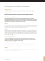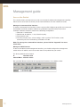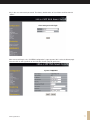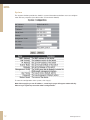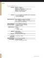
1
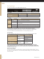
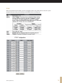
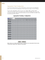
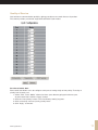
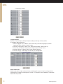
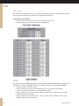
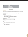
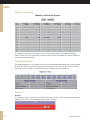
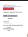
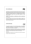
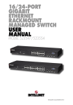
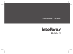
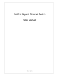
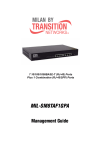
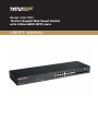
Model: 065-7932
16-Port Gigabit Web Smart Switch
with 4 Mini-GBIC (SFP) slots
USER´S MANUAL
USER´S
MANUAL
Contents
COPYRIGHT
FCC WARNING
CE
Unpacking Information
5
Introduction
5
General Description
Key Features
The Front Panel
The Rear Panel
Installation
Desktop Installation
Rack Installation
Installing Network Cables
Description of Switch Functions
Jumbo Frame
Flow Control and Backpressure
Mirror
VLAN
Trunk (Aggregation)
Quality of Service (QoS)
SNMP
Management guide
Access the Switch
Homepage
System
Port
VLAN
PVID
Aggregation/ Trunk Configuration
Quality of Service
Mirror
Rate Limit
SNMP
Discovery
Statistics Overview
Detailed Statistics
Restart
2
4
4
4
5
5
6
7
7
7
7
8
9
9
9
9
9
9
9
9
10
10
11
12
13
14
15
16
17
19
20
20
21
22
22
22
www.signamax.eu
Factory Default
Smart Boot
Software Upload
Product Specifications
Appendix – Command Line Interface
Start-up and Terminal configuration
Login/Logout Procedures
Command Hierarchy
Entering Commands
Command Description
System Commands
Console Commands
Port Commands
VLAN Commands
Aggregation Commands
QoS Commands
Mirror Commands
IP Commands
SNMP Commands
Ratelimit Commands
www.signamax.eu
23
23
23
24
25
25
25
25
26
26
26
27
27
28
30
30
31
32
32
33
3
USER´S
MANUAL
COPYRIGHT
All rights reserved. No part of this publication may be reproduced, stored in a retrieval system,
or transmitted in any form or by any means, whether electronic, mechanical, photo copying,
recording or otherwise, without the prior written permission of the publisher.
FCC WARNING
This equipment has been tested and found to comply with the limits for a class A device,
pursuant to part 15 of FCC rules. These limits are designed to provide reasonable
protection against harmful interference in a commercial installation. This equipment generates,
uses and can radiate radio frequency energy and, if not installed and used in accordance with
the nstructions, may cause harmful interference to radio communication. Operation of this
equipment in a residential area is likely to cause harmful interference, in which case, the user
will be required to correct the interference at the user’s own expense.
CE
This is a Class A product. In a domestic environment, this product may cause radio
interference in which case the user may be required to take adequate measures.
Take special care to read and understand all the content in the warning boxes.
4
www.signamax.eu
Unpacking Information
Congratulations on purchasing this 16-port Gigabit Web Smart Switch with 4 Mini-GBIC
Combo slots. Before you start, please verify that your package contains the following items:
1. One 16-port Gigabit Web Smart Switch with 4 SFP slots.
2. One power cord.
3. Rack-mounting brackets and screws (optional).
4. User Manual CD.
Introduction
General Description
This Switch will instantly boost your networking throughput because it provides you with 16
Gigabit ports that enable true Gigabit connectivity. Users are now able to transfer large and
bandwidth-hungry files faster and hence get a real efficiency improvement. This efficiency is
further enhanced by the user-friendly Web-based management interface. In addition to the
16 copper ports, the Switch offers 4 fiber ports (slots) that can be used in the place of the
last 4 copper ports (these are interchangeable or ‘combo’ ports). These mini-GBIC slots offer
the option of a long-distance, fiber-based connection. Use of a mini-GBIC port automatically
disables its corresponding copper port.
The management functions enable efficient network usage. VLAN reduces the collisions
caused by broadcasting. Port Aggregation enlarges the bandwidth of the backbone
connection. QoS secures the bandwidth for some bandwidth-hungry applications like VoIP
and video conferencing. The Switch also supports 802.3x and backpressure flow control
mechanisms to ensure the correctness of data transmission.
Key Features
•
•
•
•
•
•
•
•
•
•
•
•
•
•
•
•
16 (sixteen) 10/100/1000Mbps Gigabit Ethernet ports
4 (four) SFP slots for optional fiber connection
Supports auto-detection for mini-GBIC module insertion
Auto-discovery function for easy Network management
8K MAC address entries and 16 groups VLAN table
Supports Port Mirroring
Supports up to 8 ports and 8 groups port aggregation
Supports QoS: port-based, tag-based, DSCP priority
Supports full-duplex flow control and half-duplex backpressure
Supports Rate Limit (ICMP Rate, Broadcast Rate, Multicast Rate and Ingress/Egress Rate)
Supports Jumbo frame 9K bytes
Supports 340K bytes buffer Memory
Supports Web-based management interface
Non-blocking wire-speed switching performance
Supports firmware upgrade, SNMP
FCC Class A, CE, VCCI. RoHS-compliant
www.signamax.eu
5
USER´S
MANUAL
The Front Panel
The front panel features all the LED indicators and ports:
Device LED:
LED
Power (PWR)
Status
Steady Green
Off
Operation
The switch is powered on
The switch is powered off
Port LEDs:
LEDs
Status
Green
Blinking Green
1000M
Off
Operation
The Port is connected at 1,000 Mbps
A valid link is established and there is data transmitting/receiving
No valid link on this Port or the Port is connected
at 10/100 Mbps
Steady Green A valid link is established and there is data transmitting/receiving
10/100M Blinking Green A valid link is established and there is data transmitting/receiving
Off
No valid link on this Port or the Port is connected at 1,000 Mbps
ATTENTION: The mini-GBIC (SFP) slots share their LED indicators with their
interchangeable Gigabit RJ-45 (copper) ‘combo’ ports (the last 4 copper ports).
Use of a mini-GBIC slot automatically disables its corresponding copper port.
Port Operation
The auto-negotiation feature allows ports to run at one of the following operation modes:
Media
Speed
Duplex Mode
Full Duplex
10 Mbps
Half Duplex
10/100/1000 Mbps
Full Duplex
(cooper)
100 Mbps
Half Duplex
1,000 Mbps
Full Duplex
1000 Mbps (fiber)
1,000 Mbps
Full Duplex
mini-GBIC required
Note: For the interchangeable (combo) ports (the last 4 RJ-45 ports and the fiber
slots), if both the fiber and copper interfaces of an interchangeable pair (combo) are
connected (incorrect set-up), the system automatically accepts the fiber interface and
disables the copper port.
Restore Default Button
You can use this button to reset the switch or restore it to its factory default settings. To reset
the switch, press the button once. To restore factory default settings, press and hold the button
for three seconds.
6
www.signamax.eu
The Rear Panel
Power Receptacle
To be compatible with electricity standards around the world, the Switch is designed to work
with voltages between 100 and 240V AC and 50/60Hz. Please make sure that your region’s
electricity supply is within this range.
To power on the Switch, please plug the female end of the power cord firmly into the receptacle
of the Switch and the other (male) end into an electricity outlet (usually a wall plug). After
plugging in the power cord, check if the power LED is lit to indicate normal power status.
Installation
This Switch can be placed on your desktop or mounted in a rack. Installation is very easy.
Users can use all the features of the Switch by simply attaching the cables and turning the
power on.
Before installing the Switch, we strongly recommend that …
1. ...the Switch must be placed in an environment that is well ventilated – a minimum space
around the unit of 25mm is recommended.
2. ...the Switch and relevant components are far from sources of electrical noise, such as
radios, transmitters and broadband amplifiers.
3. ...the Switch’s environment is protected from high levels of humidity.
Desktop Installation
1. Install the Switch on a level surface that can support the weight of the unit
and the relevant components.
2. Plug the Switch’s power cord into the power outlet.
Rack Installation
Rack mounting enables orderly installation in cases where many networking devices have to be
installed in the same area. The Switch is supplied with brackets and screws for rack-mounting
purposes.
1. Disconnect all cables from the Switch before mounting it.
2. Place the unit the right way up on a hard, flat surface with the front facing you.
3. Locate a mounting bracket over the mounting holes on one side of the unit.
4. Insert the screws and tighten them with a suitable screwdriver.
5. Repeat this for the other side of the unit.
6. Slide the unit into the rack and secure it with suitable screws.
7. Reconnect all the cables.
www.signamax.eu
7
USER´S
MANUAL
Installing Network Cables
1. Crossover or straight-through cable: All the ports on the Switch support Auto-MDI/
MDI-X functionality. Both straight-through and crossover cables can be used to connect
the Switch with PCs and other devices like switches, hubs or router.
2. Category 3,4,5 or 5eUTP/STP cable: To make a valid connection and obtain optimal
performance, it is vital to use the appropriate cables that correspond to the different
transmitting/receiving speeds.
3. To choose a suitable cable, please refer to the following table:
Media
10/100/1000 Mbps
(cooper)
1000 Mbps (fiber)
mini-GBIC required
8
Speed
10 Mbps
100 Mbps
1,000 Mbps
1,000 Mbps
Wiring
Category 3, 4, 5 UTP/STP
Category 5 UTP/STP
Category 5, 5E UTP/STP
The cable type differs according to the
mini-GBIC you choose. Please refer to the
instructions that came with your mini-GBIC.
www.signamax.eu
Description of Switch Functions
Jumbo Frame
The Switch supports Jumbo Frames, which means that it can transmit the same data in
fewer frames. This helps to ensure fewer overheads, shorter processing time, and fewer
interruptions.
NOTE: To enable Jumbo Frame, Flow Control should be enabled in advance.
Flow Control and Backpressure
Flow Control and Backpressure both help devices with different processing speeds to
communicate with each other. This ensures the correctness of data transmissions. The 802.3x
Flow Control and Backpressure mechanisms work respectively for full- and half-duplex modes.
Flow Control can be enabled or disabled on a per-port basis.
Mirror
The Mirror function enables network administrators to monitor all traffic. By forwarding a copy of
the packets that are transferred by the monitored port, the sniffer port receives all the packets
and hence is able to monitor the traffic through the specified port.
VLAN
This Switch supports Virtual LAN, which means the network can be segmented into groups to
reduce collisions caused by wide broadcasting. The Switch supports both port-based VLAN
and 802.1q tag-based VLAN. Port-based VLAN directs incoming packets to VLANs according
to their ingress ports. 802.1q-based VLAN adds a tag to the header of the packet to direct the
packet to the right VLAN.
Trunk (Aggregation)
The Trunk function groups several ports into one combined transmission channel. This
increases the bandwidth, which helps to boost backbone connectivity. The Switch allows a
maximum of 4 groups and 8 members for each group.
Quality of Service (QoS)
QoS classifies packets into different precedence classes. The packets are transmitted
and received according to their classified priorities. This mechanism helps high-bandwidth
demanding applications such as VoIP to get an unobstructed connection.
SNMP
The Switch supports SNMP (Simple Network Management Protocol). It allows the product to be
monitored by an SNMP management station.
www.signamax.eu
9
USER´S
MANUAL
Management guide
Access the Switch
This section shows you how to access and use the Switch’s advanced management capability,
which can be accessed via console port or Internet Browser over the network (in-band).
Manage via Command Line Interface
To start the Command Line Interface, please connect a PC COM port to the RS-232 connector
and activate a terminal emulation software (e.g. Windows’ HyperTerminal) The terminal
emulation software should be started in the following configuration:
1. Data rate: 115200 baud.
2. Data format: 8 data bits, 1 stop bit and no parity.
3. Flow control: none.
4. Click the property icon, select settings, make sure that: The Function, arrow,
and ctrl keys act as: Terminal keys, Emulation: VT100.
Note: To manage via command line interface, please find the “Appendix” for more
information.
Manage via Web Browser
To access the Web-based management interface, you should configure the management
station with an IP address and subnet mask that is compatible with your switch.
The factory defaults of the Switch:
IP
192.168.0.254
Subnet Mask 255.255.255.0
Run your Web Browser and enter the appropriate IP address in the Address field:
10
www.signamax.eu
Key in the user name and password. The factory default value of User Name and Password is
“admin”.
Homepage
After successful log-in, the “SYSTEM Configuration” page appears (this is also the Homepage).
You can click on the hyperlinks on the left side of each page to get access.
to each management function.
www.signamax.eu
11
USER´S
MANUAL
System
The System window provides the Switch’s system information and allows users to configure
most of these properties (see table under screenshot for details).
To save the configuration of the system, click “Apply”.
Note: After applying a new IP address, a new log-in page will appear automatically.
Please log in again to proceed to other configurations.
12
www.signamax.eu
Port
This Port Configuration page shows the link status of each port and allows users to configure
speed, flow control and maximum frame size for each port.
To save the configuration of the system, click “Apply”. You can also click the “Refresh” button to
show the updated statuses of the ports.
www.signamax.eu
13
USER´S
MANUAL
VLAN
VLAN divides the network members into groups to reduce packet collisions and improve the
network efficiency. The switch supports 802.1q tag-based VLAN. Please follow the instructions
to configure.
To add new VLAN groups,
1. Fill in a VLAN ID, from 2 to 4094, in the “VLAN\Port” column.
2. Select the ports for each VLAN group.
3. Click the “Apply” button to execute.
To delete a VLAN group
1. Remove the members of the VLAN group by unmarking their marked checkboxes.
2. Clear the VLAN ID of the VLAN you want to remove in the “VLAN\Port” column.
(Don’t type N/A. Just leave it blank.)
3. Click the “Apply” button to execute.
14
www.signamax.eu
PVID
When the VLAN-enabled Switch receives a tagged packet, the packet will be sent to the port’s
default VLAN according to the PVID (port VLAN ID) of the receiving port.
www.signamax.eu
15
USER´S
MANUAL
Aggregation/ Trunk Configuration
To set up the port trunk groups, put the selected ports’ numbers into the same Aggregation
group. You can choose up to eight groups. Don’t forget to click “Apply” to save the settings.
There are three aggregation modes for you to set up, SMAC, DMAC, and XOR. SMAC
mode selects the path of packets according to Source MAC while DMAC mode selects path
according to Destination MAC. XOR mode calculates the result of the DMAC and SMAC modes
to decide the path of the packets.
Note: Settings in VLAN, Port Aggregation, and Mirror are co-dependent. Please make
sure that the settings won’t influence one another.
16
www.signamax.eu
Quality of Service
QoS enhances communication quality by giving precedence to certain classes of packets.
This switch provides port-based, tag-based and DSCP QoS modes:
Port-based mode QoS:
Port-based QoS allows users to configure each port as having a high or low priority. To assign a
priority level to each port:
1. Select “Port” in the “Mode” column for those ports that are going to function as part
of port-based QoS. Click the “Apply” button.
2. Click the “Port priority” button. The “Port Priority Setting” appears.
3. Click on the drop menu to specify priority levels.
4. Click “Apply” to execute.
www.signamax.eu
17
USER´S
MANUAL
Tag-based QoS:
Tag-based QoS assigns packet priority according to the tags on the packets.
To configure Tag-based QoS:
1. Select “Tagged” in the “Mode” column for those ports that are going to perform
tag-based QoS. Click the “Apply” button.
2. Click the “Tag priority” button. The “Tag Priority Setting” page shows up.
3. Select the port that you are going to configure from the drop menu.
4. Set the priorities as high or low for each Priority Tag type.
5. Click the “Apply” button again to execute your configuration.
DSCP-mode QoS:
DSCP-mode QoS assigns packet priority according to the types of the incoming packets.
It distinguishes packets according to the “Delay”, “Throughput” and “Reliability” information
attached to the packet.
18
www.signamax.eu
The types are listed as the following:
Bit 0 (Delay)
Bit 1 (Throughput)
0 (Normal)
0 (Normal)
1 (Low)
1 (High)
Bit 3 (Reliability)
0 (Normal)
1 (High)
Note: The Switch distinguishes packets with DSCP precedence “000(routine)” only.
To configure DSCP-based QoS configuration:
1. Select “DSCP” in the “Mode” column for those ports that are going to perform
DSCP-based QoS. Click the “Apply” button.
2. Click the “DSCP priority” button. The “DSCP Priority Setting” page shows up.
3. Set the priorities as high or low for each precedence type.
4. Click the “Apply” button again to execute your configuration.
Mirror
The Mirror function copies all the packets that are transmitted by the source port to the
destination port. It allows administrators to analyze and monitor the traffic of the monitored
ports.
Mirror Configuration:
1. Select those ports that are going to be monitored by marking the checkboxes in
the “Monitor Port” column.
2. Click the drop menu in the “Sniffer Port” column. Select a port as the administration
port for monitoring those source ports.
3. Click “Apply” to activate.
www.signamax.eu
19
USER´S
MANUAL
Rate Limit
The “Rate Limit” page allows users to limit the bandwidth for each port and configure the rules
for Storm Control, which limits the flow of broadcast and multicast.
To perform storm control:
1. Click on each drop list to specify a speed for each frame type.
2. Click the “Apply” button to execute your configuration.
SNMP
This device supports SNMP-management, which allows network administrators to monitor and
configure this device with SNMP software. To allow this device to be managed via SNMP:
1. Select “enable” in the drop menu.
2. Specify a trap IP. A trap IP is the destination port for sending trap information,
which is usually the IP address of network administrators.
3. Fill in a name in the “Community Get” column, which is the password for accessing
MIB with read-only authority.
4. Fill in a name in the “Community Set” column, which is the password for accessing
MIB with read-and-write authority.
20
www.signamax.eu
Discovery
After installing a series of our switches, the discovery management tool helps users to search
and get access to those switches within the LAN.
Note: The discovery tool lists a maximum of 16 devices respectively for auto and
manual modes.
Auto Search
1. Click the “Apply” button to start.
2. The devices being found are listed below.
3. Click the IP address hyperlink to get access to the device.
Manual Add
Add
1. Enter the IP address & name in the text box.
2. Click “Add” to add the new IP address on the table.
Delete
1. Click the check box of the one you want to remove.
2. Click “Delete” to remove.
www.signamax.eu
21
USER´S
MANUAL
Statistics Overview
The Statistics Overview is provided for users to see the general transmitting and receiving
status of each port. You may click the “Clear” button to clean all statistics or click the “Refresh”
button to renew the statistics.
Detailed Statistics
The Detailed Statistics is provided for users to see the detailed transmitting and receiving status
of each port. Please click the hyperlinks above to select a port. You may also click the “Clear”
button to clean all statistics or click the “Refresh” button to renew the statistics.
Restart
Restart:
To restart the system, click the “Yes” button. The system restarts and shows the authentication
window. Please fill in the username and password to continue.
22
www.signamax.eu
Factory Default
Restore Factory Default:
To restore the factory default settings, click the Yes button.
Note: The IP address of the device will also be reconfigured to the factory default
setting, which is 192.168.0.254.
Smart Boot
This Smart Boot page allows users to select the booting flash of the device. ”Active image
number” shows the current flash for booting the device. To change the booting flash, click
on the appropriate flash in the “Boot image number” column and click the “Apply” button to
execute.
Software Upload
This “Software Upload” page allows users to upgrade firmware for this Switch.
To perform firmware upgrade:
1. Click the “Browse” button.
2. Locate the firmware file.
3. Click the “Upload” button to execute.
Note: This new firmware is going to be applied on the remaining flash that you have
NOT selected in “Smart Boot”, that is, the new firmware is going to be applied on the
flash that is NOT chosen as the booting flash. Please ensure that you boot this device
with the correct flash before performing a firmware upgrade.
www.signamax.eu
23
USER´S
MANUAL
Product Specifications
s
24
www.signamax.eu
Appendix – Command Line Interface
Start-up and Terminal configuration
To start the Command Line Interface, please connect a PC COM port to the RS-232 connector
and activate a terminal emulation software (e.g. Windows’ HyperTerminal).
The terminal emulation software should be started in the following configuration:
1. Data rate: 115200 baud.
2. Data format: 8 data bits, 1 stop bit and no parity.
3. Flow control: none.
4. Click the property icon, select settings, make sure that: The Function, arrow,
and ctrl keys act as: Terminal keys, Emulation: VT100.
Login/Logout Procedures
To get access to the CLI, you will have to get the username and password for login. The default
username and password are “admin” and “admin”.
Note: We recommend that you configure a new username and password to prevent
unauthorized users from accessing the device.
Command Hierarchy
After logging in, press ? + <enter> to show the 9 command groups.
System
- System commands
Console
- Console commands
Port
- Port commands
VLAN
- VLAN commands
Aggr
- Aggregation commands
QoS
- QoS commands
Mirror
- Mirror commands
IP
- IP commands
SNMP
- SNMP commands
Ratelimit
- Rate setup commands
Exit
- Logout commands
Press ? or help to get help. The help depends on the context (where you are in the program):
- At top level, a list of command groups will be shown.
- At group level, a list of the command syntaxes will be shown.
- If given after a command, the syntax and a description of the command will be shown.
www.signamax.eu
25
USER´S
MANUAL
Entering Commands
To give any command, please key in your command and press enter.
Example:
1. Type “system” and press <enter> to get access to the system command group.
2. Type “Configuration” and press <enter> to perform “configuration”.
You can type “up” and press <enter> to go back to the upper level.
Command Description
These are the group commands of the command line interface:
Command groups:
System
- System commands
Console
- Console commands
Port
- Port commands
VLAN
- VLAN commands
Aggr
- Aggregation commands
QoS
- QoS commands
Mirror
- Mirror commands
IP
- IP commands
SNMP
- SNMP commands
Ratelimit
- Rate setup commands
Exit
- Logout commands
System Commands
Commands at System level:
System Configuration [all]
System Restore Default [keepIP]
System UserName [<name>]
System Password [<password>]
System Systemname [<name>]
System Reboot
System Configuration [all]
Syntax:
System Configuration [all]
Description:
Show system name, username, password, software version and management MAC
address. Optionally show the full configuration.
[all]: Show the total switch configuration (default: System configuration only).
System Restore Default [keepIP]
Description:
Restore factory default configuration.
[keepIP]: Preserve IP configuration (default: Not preserved).
26
www.signamax.eu
UserName [<name>]
Description:
Set or show the user name.
[<name>]: String of up to 16 characters (default: Show user name).
System Password [<password>]
Description:
Set or show the console password. The empty string (“”) disables the password check.
[<password>]: Password string of up to 16 characters.
System Systemname [<name>]
Description:
Set or show the system name.
[<name>]: String of up to 16 characters (default: Show system name).
System Reboot
Description:
Reboot the switch.
Console Commands
Commands at Console level:
Console Configuration
Console Timeout [<timeout>]
Console Prompt [<prompt string>]
Console Configuration
Description:
Show configured console prompt and timeout
Console Timeout [<timeout>]
Description:
Set or show the console inactivity timeout in seconds. The value zero disables timeout.
[<timeout>]: Timeout value in seconds, 0,60-10000.
Console Prompt [<prompt_string>]
Description:
Set or show the console prompt string.
[<prompt_string>]: Command prompt string of up to 10 characters
Port Commands
Commands at Port level:
Port Configuration [<portlist>]
Port Mode [<portlist>] [<mode>]
Port Flow Control [<portlist>] [enable|disable]
Port Admin [<portlist>] [enable|disable]
Port MaxFrame [<portlist>] [<framesize>|reset]
Port Statistics [<portlist>] [clear]
Note: If you want to make maxframe bigger than 1518, the [Flow Control] should be
enabled!
www.signamax.eu
27
USER´S
MANUAL
Port Configuration [<portlist>]
Description:
Show the configured and current speed, duplex mode, flow control mode and admin state for
the port.
[<portlist>]: Port list (Default: All ports).
Port Mode [<portlist>] [<mode>]
Description:
Set or show the speed and duplex mode for the port.
[<portlist>]: Port list (Default: All ports).
[<mode>]: Port speed and duplex mode (Default: Show configured and current mode).
10hdx: 10 Mbit/s, half duplex
10fdx: 10 Mbit/s, full duplex
100hdx: 100 Mbit/s, half duplex
100fdx: 100 Mbit/s, full duplex
1000fdx: 1 Gbit/s, full duplex
auto: Auto negotiation of speed and duplex.
Port Flow Control [<portlist>] [enable|disable]
Description:
Set or show flow control mode for the port.
[<portlist>] : Port list (default: All ports).
[enable|disable]: Enable/disable flow control (default: Show flow control mode).
Port Admin [<portlist>] [enable|disable]
Description:
Set or show the admin state for the port.
[<portlist>] : Port list (default: All ports).
[enable|disable]: Enable or disable admin state (default: Show admin state).
Port MaxFrame [<portlist>] [<framesize>|reset]
Description:
Set or show the maximum frame size in bytes (including FCS) for frames received on the port.
Tagged frames are allowed to be 4 bytes longer than the maximum frame size. Use the reset
option to return to default setting.
[<portlist>]: Port list (default: All ports).
[<framesize>|reset]: Maximum frame size [1518-9216] or reset to 1518 bytes (default: Show
maximum frame size)
Port Statistics [<portlist>] [clear]
Description:
Show or clear statistics for the port.
[<portlist>]: Port list (default: All ports).
[clear] : Clear port statistics (default: Show statistics).
VLAN Commands
Commands at VLAN level:
VLAN Configuration [<portlist>]
VLAN Add <vidlist> [<portlist>]
VLAN Delete <vidlist>
28
www.signamax.eu
VLAN Lookup <vidlist>
VLAN Egress [<portlist>] [untagged|tagged]
VLAN PVID [<portlist>] [<vid>|none]
VLAN OnlyTag [<portlist>] [enable|disable]
VLAN Configuration [<portlist>]
Description:
Show the VLAN egress mode, port VLAN ID and accepted frame type for the port and
the permanently stored VLAN table.
[<portlist>]: Port list (default: All ports).
VLAN Add <vidlist> [<portlist>]
Description:
Add VLAN entry and include ports in member set.
<vidlist>: VLAN ID list.
[<portlist>]: Port list (default: All ports).
VLAN Delete <vidlist>
Description:
Delete VLAN entry (all ports excluded from member set).
<vidlist>: VLAN ID list.
VLAN Lookup <vidlist>
Description:
Lookup VLAN entry and show port list.
<vidlist>: VLAN ID list.
VLAN Egress [<portlist>] [untagged|tagged]
Description:
Set or show the VLAN egress mode setting for the port. Egress untagged ports will strip
the VLAN tag from received frames.
Egress tagged ports will not strip the tag from received frames
[<portlist>]: Port list (default: All ports).
[tagged|untagged]: (default: Show egress tag setting).
VLAN PVID [<portlist>] [<vid>|none]
Description:
Set or show the port VLAN ID. Untagged frames received on the port will be classified to this
VLAN ID. Frames classified to this VLAN ID will be sent untagged on the port.
[<portlist>]: Port list (default: All ports).
[<vid>|none]: Port VLAN ID, 1-4094 (default: Show PVID).
The ‘none’ option can be used for trunk links.
VLAN OnlyTag [<portlist>] [enable|disable]
Description:
Set or show the onlytag setting of this port.
[<portlist>]: Port list (default: All ports).
[enable|disable]: Only accept tagged frame or not (default: Show disable).
www.signamax.eu
29
USER´S
MANUAL
Aggregation Commands
Commands at Aggr level:
Aggr Configuration
Aggr Add <portlist>
Aggr Delete <portlist>
Aggr Lookup <portlist>
Aggr Mode [smac|dmac|xor]
Aggr Configuration
Description:
Shows the aggregation groups and the aggregation mode.
Aggr Delete <portlist>
Description:
Delete link aggregation group.
<portlist>: Port list. Aggregations including any of the ports will be deleted.
Aggr Lookup <portlist>
Description:
Look up and display link aggregation group.
<portlist>: Port list. Aggregations including any of the ports will be shown.
Aggr Mode [smac|dmac|xor]
Description:
Set or show link aggregation traffic distribution mode.
[smac|dmac|xor]: Aggregation mode, SMAC, DMAC or XOR (default: Show mode).
QoS Commands
Commands at QoS level:
QoS Configuration [<portlist>]
QoS Mode [<portlist>] [tag|port|diffserv]
QoS Port [<portlist>] [<class>]
QoS Tagprio [<portlist>] [<tagpriolist>] [<class>]
QoS DiffServ [<dscpno>] [<class>]
<class> range: low|normal|medium|high
QoS Configuration [<portlist>]
Description:
Show the configured QoS mode and the priority setting of all ports.
[<portlist>]: Port list (default: All ports).
QoS Mode [<portlist>] [tag|port|diffserv]
Description:
Set or show the QoS mode for the port.
[<portlist>]: Port list (default: All ports).
[tag|port|diffserv]: Enable tag, port or IP differentiated services class of service for the port
(default: Show mode).
30
www.signamax.eu
QoS Port [<portlist>] [<class>]
Description:
Set or show the port class. In tag mode, the default class is used for untagged frames. In port
mode, the default class is used as the port priority. In diffserv mode, the default class is used
for non-IP frames.
[<portlist>]: Port list (default: All ports).
[<class>]: Internal class of service (default: Show default class).
QoS Tagprio [<portlist>] [<tagpriolist>] [<class>]
Description:
Set or show the VLAN user priority mapping.
[<portlist>]: Port list (default: All ports).
[<tagpriolist>]: VLAN user priority list, 0-7 (default: All user priorities).
[<class>]: Internal class of service (default: Show class).
QoS DiffServ [<dscpno>] [<class>]
Description:
Set or show the IP Differentiated Services mapping.
[<dscpno>]: IP DSCP number, 0-7.
[<class>]: range: low|normal|medium|high
Mirror Commands
Commands at Mirror level:
Mirror Configuration
Mirror Port [<port>]
Mirror Source [<portlist>] [enable|disable]
Mirror Configuration
Description:
Show the mirror destination port and mirror mode for source ports.
Mirror Port [<port>]
Description:
Set or show the mirror destination port.
[<port>]: Mirror destination port (default: Show mirror port).
Mirror Source [<portlist>] [enable|disable]
Description:
Set or show the source port mirror mode.
[<portlist>]: Source port list (default: All ports).
[enable|disable]: Enable/disable mirroring of frames received on port (default: Show mirror
mode).
www.signamax.eu
31
USER´S
MANUAL
IP Commands
Commands at IP level:
IP Configuration
IP Setup [<ipaddress> [<ipmask> [<ipgateway>] [<vid>]
IP Web management [enable|disable]
IP Configuration
Description:
Show IP configured IP address, mask, gateway, VLAN ID and mode.
IP Setup
Description:
Setup or show IP configuration.
[<ipaddress>]: IP address. (default: Show IP configuration)
[<ipmask>]: IP subnet mask (default: Subnet mask for address class).
[<ipgateway>]: Default IP gateway, (default: 0.0.0.0).
[<vid>]: VLAN ID, 1-4094 (default: 1).
IP Web management
Description:
Activate or deactivate the Web management.
[enable|disable]: Enable/disable Web management. (default: Show Web management)
SNMP Commands
Commands at SNMP level:
SNMP Configuration
SNMP Community [<get>|<set>] [<community>]
SNMP Setup [enable|disable]
SNMP Trap [<IP Address>]
SNMP Configuration
Description:
Show the SNMP configuration.
SNMP Community [<get>|<set>] [<community>]
Description:
Set or show community setting for SNMP
[<get>|<set>]: Community for get or set
[community]: community string
SNMP Setup [enable|disable]
Description:
Activate or deactivate the SNMP.
[enable|disable]: Enable/disable SNMP (default: Show SNMP mode).
SNMP Trap [<IP Address>]
Description:
Set or show SNMP traps destination.
<IP Address>: IP address to send traps to. (default: Show trap configuration)
32
www.signamax.eu
Ratelimit Commands
Commands at Ratelimit level:
Ratelimit Configuration
Ratelimit Setup <traffic type> <option>
Ratelimit Egress [<portlist>] [enable|disable] [<rate>]
Ratelimit Ingress [<portlist>] [enable|disable] [<rate>]
[<portlist>]: Port list (default: All ports).
[enable|disable]: Enable or disable.
[<rate>]: Set leaky bucket rate in Kbit/s [128/256/512/1024/2048/3072K]
(default: Show rate).
Ratelimit Configuration
Description:
Show the Ratelimit setting.
Ratelimit Setup <traffic type> <option>
Description:
Set or show the ratelimit configuration. The allowed frame rates for ICMP frames, learn frames,
multicasts, broadcasts and flooded unicasts are controlled using a central ratelimit.
[<traffic type>]: Ratelimit to set. Can be one of: [ICMP|Broadcast|Multicast] (default: Show all).
[enable|disable]: Enable or disable specified ratelimit.
[<rate>]: Frame rate in kiloframes.
Allowed values are 1k, 2k, 4k, 8k, 16k, 32k, 64k.
www.signamax.eu
33
K E E P I N G
YO U R
WO R L D
C O N N E C T E D
www.signamax.eu