1
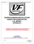
CA-110 Installation Instructions
PROFESSIONAL INSTALLATION
STRONGLY RECOMMENDED
Installation Precautions:
Kit Contents
Roll down window to avoid locking
keys in vehicle during installation
(1) - Control Module
Avoid mounting components or
routing wires near hot surfaces
(1) - Multi Pin Input/Output Harness
Avoid mounting components or
routing wires near moving parts
(1) - IRS-Shock Sensor
Tape or loom wires under hood
for protection and appearance
(1) - Literature Package
(2) - 2 Button High Frequency Transmitters
(1) -2 Pin Door Lock Harness
(1) - Programming Switch
(1) - Siren
Use grommets when routing wires
through metal surfaces
Use a voltmeter for testing and
verifying circuits
Technical Support
For Authorized Dealers (800) 421-3209
FCC COMPLIANCE
This device complies with Part 15 of the FCC rules and with RSS-210 of Industry Canada. Operation is subject to the following two conditions:
1. This device may not cause harmful interference, and
2. This device must accept any interference received, including any interference that may cause undesired operation.
Warning!
Changes or modifications not expressly approved by the party responsible for compliance could void the user’s authority to operate the equipment.
128-6832
1 of 16
INSTALLATION OF THE MAJOR COMPONENTS
Control Module:
Select a mounting location inside the passenger compartment (behind the dash), and secure using the
two screws provided. The control module can also be secured in place using cable ties. Be certain that the
chosen location will not interfere with the proper operation of the vehicle. Avoid mounting the module to or
routing the wiring around the steering shaft/column, as the module or wiring may wrap around or block the
steering wheel preventing proper control of the vehicle. Secure the module in the chosen location using
cable ties or screws as necessary. Do not mount the module in the engine compartment, as it is not
waterproof.
Siren:
Select a location in the engine compartment that is not accessible from below the vehicle. The selected
location must be clear of hot or moving parts within the engine compartment The siren must be pointed
downward to prevent water retention and the flared end must be pointed away from and out of the engine
compartment for maximum sound distribution. Before securing the siren, check behind your chosen
location to assure that the mounting screws will not penetrate any factory wiring or fluid lines. Secure the
siren mounting bracket using #8 self taping screws or by first using the mounting bracket as a template,
scribe or mark the mounting holes. Drill the marked holes using a 1/8" drill bit, then mount the siren using
#8 sheet metal screws.
Dash Mounted LED:
A small Red LED included in the kit will serve as a visual indicator of the alarm's status. It should be
installed in the dash, located where it can be easily seen from outside the vehicle, yet not be distracting to
the driver. Once a location has been selected, check behind the panel for wire routing access, and to
confirm the drill will not damage any existing components as it passes through the panel. Drill a 1/4" hole,
and pass the red and blue wires from the LED through the hole, from the front of the panel. Firmly press the
body of LED into the hole until fully seated.
Valet/Programming/Hi-Jack Override Switch
Select a mounting location that is within reach of the ignition switch, as this switch in combination with the
ignition switch, will be used to program the certain features of the system. It is suggested that the switch be
mounted to the lower dash panel in the driver's area within reach of the driver.
Two Stage IR-s Shock Sensor:
Select a solid mounting surface for the shock sensor inside the passenger compartment (behind the dash),
and mount the sensor using cable ties, making sure to allow access to the sensitivity adjustment
potentiometer for use later in the installation.
2
128-6832
2 of 16
WIRING THE SYSTEM
Red: +12 VDC CONSTANT BATTERY SOURCE
Connect this wire to a +12 Volt constant source found at the vehicles ignition switch. This wire provides
power for the control module.
Orange: 300 mA Ground Output When Armed -N.C. Starter Disable
This wire is provided to control the starter disable relay. Connect the orange wire to terminal 86 of the
relay. Connect relay terminal 85 to an ignition wire in the vehicle that is live when the key is in the ON and
CRANK positions, and OFF when the key is in the OFF position. (this is where the pink wire from the
alarm should be connected).
Cut the low current starter solenoid wire in the vehicle (usually found at the ignition switch), and connect
one side of the cut wire to relay terminal 87A. Connect the other side of the cut wire to relay terminal 30.
NOTE: This is a normally closed starter disable arrangement, and when power is removed from the system,
the starter disable feature will not operate, allowing the vehicle to start. Code Systems does not
recommend using the Orange wire to interrupt anything but the starting circuit of the vehicle.
White: Parking Light Output (+/- 15 AMP MAX)
This wire is provided to flash the vehicle’s parking lights. Connect the white wire to the output side of one
of the vehicle’s parking lights.
White w/Red: Parking Light Polarity Input
This wire is provided as a polarity input of the pulsed parking light output relay.
a) For vehicles with positive switching parking lights. Connect the White/Red wire to a +12 VDC constant
battery source.
b) For vehicles with negative switching parking lights. Connect the White/Red wire to a solid chassis
ground source.
Black w/Red: Positive Siren Output
Route this wire through a rubber grommet in the firewall, and to the siren location.
Connect the Black/Red wire to the positive wire of the siren. Secure the black ground wire of the siren to
chassis ground.
Black: Chassis Ground
Connect this wire to a solid, metal part of the vehicle’s chassis. Do not confuse this wire with the thin
black antenna wire that exits the control module independently.
Tan: Delayed 200 mA Pulsed Output/Channel 2
This wire pulses to ground via an independent RF channel from the keychain transmitter. This is a
transistorized, low current output, and should only be used to drive an external relay coil.
WARNING: Connecting the Tan wire to the high current switched output of trunk release circuits, and some
remote start trigger inputs, will damage the control module.
In these cases connect the Tan wire to terminal 86 of a 30A automotive relay, and wire the remaining
relay contacts to perform the selected function of channel 2.
Brown/Black: 200 mA Horn Output
The brown/black wire is provided to beep the vehicle’s horn. This is a transistorized low current output,
and should only be connected to the low current ground output from the vehicle’s horn switch.
If the vehicle uses a +12 VDC horn switch, then connect the Brown/Black wire to terminal 86 of a relay,
and connect relay terminal 85 to a fused +12 VDC battery source. Connect relay terminal 87 to the
vehicle’s horn switch output, and connect relay terminal 30 to a fused +12 VDC battery source.
3
128-6832
3 of 16
Grey: (-) Instant Trigger Zone 2
This is an Instant ground trigger wire. It must be connected to the previously installed hood and/or
trunk pin switches.
Green: Negative Door Trigger Input
If the vehicle’s courtesy light switches have a (-) ground output when the door is opened (GM and
most Imports), you must connect the Green wire to the negative output from one of the door switches.
WARNING:
Do not use the green wire if the vehicle has +12 volt output type door switches. (see Purple Wire).
Violet: Positive Door Trigger Input
If the vehicle’s door courtesy light switches have a +12 volt output when the door is opened (most
Ford and some Imports), you must connect the Violet wire to the positive output from one of the door
switches. In most cases, the Violet wire will only needs to be connected to one door switch, no matter
how many doors the vehicle has.
WARNING:
Do not use the Violet wire if the vehicle has ground output type door switches. (see Green Wire)
Pink: (+) 12 VDC Ignition Source
Connect this wire to the ignition wire from the ignition switch. This wire will show +12 volts when the
ignition key is turned to the to the ON, RUN and START positions, and will have 0 volts when the key
is turned to the OFF and ACCESSORY positions.
2 Pin White Connector: Dash Mounted LED
Route the red and blue wires in the 2 pin white connector from the LED to the control module, and
plug it into the mating white connector on the side of the module.
2 Pin Red Connector: Valet/Programming/Override Switch
Route the 2 pin red connector from the override switch previously mounted to the mating two pin
connector on the module.
4 Pin White Connector: IRS-Shock Sensor Harness
Route the 4 pin connector from the previously installed shock sensor to the mating 4 pin connector of
the module.
4
128-6832
4 of 16
Blue & Green 2 Pin White Connector:Door Lock/Unlock Outputs
These wires will provide a pulsed ground output to the factory door lock control relay. The maximum current
draw through these outputs must not exceed 300 mA.
3 Wire Ground Switched Door Locks:
In this application, the blue wire provides a ground pulse during arming, or the pulsed ground lock output.
Connect the red wire to the wire that provides a low current ground signal from the factory door lock switch to
the factory door lock control relay.
The green wire provides a ground pulse during disarming, or the pulsed ground unlock output. Connect the
green wire to the wire that provides a low current ground signal from the factory door unlock switch to the f
factory door lock control relay.
3 Wire Positive Switched Door Locks (Relay required see Diagram 1 & 2):
Diagram1
Diagram 2
Lock
Fused + 12v
86
87
Unlock
Fused + 12v
85
86
+ 12 Volts
87a
30
85
87
+ 12 Volts
87a
30
X
X
Lock Relay
Vehilce
CUTInHERE
Unlock Relay
In Vehilce
CUT HERE
5 Wire Alternating 12 Volt (Relay required see Diagram 3 & 4):
Diagram 4
Diagram 3
Lock
Fused + 12v
86
87
87a
30
Door Lock Switch
Unlock
Fused + 12v
86
85
+ 12 Volts
Door Lock Motor
87
87a
30
Unlock Switch
85
+ 12 Volts
Unlock Motor
X
X
CUT HERE
CUT HERE
128-6832
5 of 16
COMPLETING THE INSTALLATION
Antenna Wire: Be sure to extend the thin black antenna wire to it’s full length, and cable tie into place where it
cannot be damaged. Avoid wrapping this wire around major, high current wire looms.
Adjusting the Shock Sensor: Gently turn the adjustment knob counterclockwise to turn down the sensitivity
and turn clockwise to turn up sensitivity. Close the hood and trunk lids, and arm the alarm . Wait 6 seconds
for the accessories trigger zone to stabilize, then test the sensitivity adjust as needed
CAUTION: Never perform this test on the vehicle’s glass, as you may break the window.
WARNING ! Setting the sensitivity too high can cause false alarms due to noise vibrations from passing trucks
and heavy equipment. To decrease sensitivity, turn the adjustment screw counter clockwise.
Wire Dressing: Always wrap the alarm wires in convoluted tubing, or with a spiral wrap of electrical tape.
Secure these looms along the routing using cable ties. This will ensure that the alarm wires are not
damaged by falling onto hot or sharp moving surfaces in the vehicle.
ADDITIONAL INFORMATION:
The CA-110 comes programmed with button 1, controlling Arm/Lock & Panic Button 2 operates Disarm/
Unlock and the channel 2 output’s Tan wire. Channel 3, (Both Buttons), of the transmitter controls the Anti
Hi-Jack operation when the feature is selected on. Note: The Hijack feature #9 of the module must be
selected on to take advantage of this feature. For information consult the feature programming section of
this manual. For transmitter programming information, consult the transmitter programming guide
5
128-6832
6 of 16
PROGRAMMING THE TRANSMITTERS
The keychain transmitter included with the system have been pre-programmed at the factory, with each
button pre-assigned to control a specific function of the system.
It is important to remember that during programming, each individual step of the procedure must be
executed within 15 seconds of the previous step.
When the 15 second time limit is allowed to expire, the system will automatically terminate the
programming mode. This is indicated by a long chirp from the siren.
Additionally, the system will store codes from up to 4 different
transmitters. If a 5th transmitter is programmed to any receiver channel, then the first transmitter
programmed to that channel will be erased from the system’s memory.
To program new or additional transmitters, the alarm must be disarmed:
1. Enter the vehicle, and turn the ignition key to the ON position.
2. Press and release override/pushbutton 3 times.
3. The dash LED will flash one time, and the sounding device will beep one time, indication the system is
ready to accept programming for receiver channel 1.
4. Press and hold the Arm/Disarm Icon button until the sounding device emits a long beep, indicating the
signal has been stored into memory.
5. If you have additional transmitters (up to 4) that need to be programmed, repeat step 4 for each transmitter.
Programmable Features
Select By Operating Transmitter
Press Btn 1
Press Btn 2
Press Btns1&2
Siren Indications
1 Chirp
2 Chirps
3 Chirps
1) Arming Method
Passive Arm
Active Arm
2) Ignition Control Lock/Unlock
Off
On
3) Passive Or Active Door Locks
Active
Passive
4) Single Or Double Pulse U/L
Single Pulse
Double Pulse
5) Door Lock/Unlock Pulse Duration
1 Second
3 Seconds
6) Siren Chirps On/Off
On
Off
7) Horn Chirps On/Off
On
Off
8) Passive Rearm From Active State
On
Off
9) Anti Hi-Jack Feature
Off
On
10) Horn Chirp Duration
10ms
16ms
30ms
Defalut settings are in BOLD
6
128-6832
7 of 16
To program these selectable features;
Action
Turn ignition on then back off
Press and release the valet switch 6 times
You are now in programming mode
First
Second
Third
Fourth
Fifth
Sixth
Seventh
Eighth
Ninth
Tenth
System Response
No response
1 Chirp from Siren
Press and release the valet switch (1) time BTN 1 = 1 Chirp
LED Flashes 1 time
BTN 2 = 2 Chirps
or
Press and release the valet switch (2) times BTN 1 = 1 Chirp
LED Flashes 2 times
BTN 2 = 2 Chirps
or
Press and release the valet switch (3) times BTN 1 = 1 Chirp
LED Flashes 3 times
BTN 2 = 2 Chirps
or
Press and release the valet switch (4) times BTN 1 = 1 Chirp
LED Flashes 4 times
BTN 2 = 2 Chirps
or
Press and release the valet switch (5) times BTN 1 = 1 Chirp
LED Flashes 5 times
BTN 2 = 2 Chirps
or
Press and release the valet switch (6) times BTN 1 = 1 Chirp
LED Flashes 6 times
BTN 2 = 2 Chirps
or
Press and release the valet switch (7) times BTN 1 = 1 Chirp
LED Flashes 7 times
BTN 2 = 2 Chirps
or
Press and release the valet switch (8) times BTN 1 = 1 Chirp
LED Flashes 8 times
BTN 2 = 2 Chirps
or
Press and release the valet switch (9) times BTN 1 = 1 Chirp
LED Flashes 9 times
BTN 2 = 2 Chirps
or
Press and release the valet switch (10) times BTN 1 = 1 Chirp
LED Flashes 10 times
BTN 2 = 2 Chirps
BTN1& 2 = 3 Chirps
Passive Arm
Acitve Arm
Ignition Locks
OFF
Active Door Locks
Passive Door Locks
Single Pulse D/L
Double Pulse D/L
1 Sec. Door Locks
3 Sec. Door Locks
Siren ON
Siren OFF
Horn ON
Horn OFF
Re-Arming ON
Re-Arming OFF
Anti Hi-Jack OFF
Anti Hi-Jack ON
Horn Pulse 10mS
Horn Pulse 16mS
Horn Pulse 30mS
Note : Once you enter the feature programming mode, do not allow more than 15 seconds to pass between
steps, or the programming will be terminated.
7
128-6832
8 of 16
128-6832
9 of 16
ANTENNA
DOOR UNLOCK OUTPUT (-)
SHOCK
SENSOR
L.E.D.
(PLUG-IN)
DOOR LOCK OUTPUT (-)
GREEN
BLUE
CA-110
5A
RED
FUSE
VALET/OVERRIDE
SWITCH
PINK
VIOLET
GREEN
GRAY
BROWN/BLACK
TAN
BLACK
WHITE/RED
ORANGE
BLACK/RED
WHITE
15A
ORANGE
FUSE
85
STARTER MOTOR SIDE
STARTER KEY SIDE
SWITCHED
+12VOLTS
IGNITION
BLACK
SWITCHED +12VOLTS IGNITION
POSITIVE DOOR TRIGGER INPUT (+)
NEGATIVE DOOR TRIGGER INPUT (-)
NEGATIVE HOOD/TRUNK TRIGGER (-)
HORN OUTPUT (LOW CURRENT (-)
CHANNEL 2 OUTPUT (-)
CHASSIS GROUND
RED
PARKING LIGHT POLARITY
PARKING LIGHT OUTPUT
WHITE
RED
BLACK
86
87
30
87A
+12 VOLTS CONSTANT