1
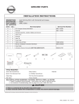
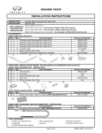
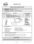
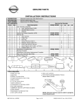
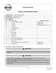
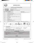
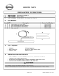
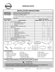
GENUINE PARTS
INSTALLATION INSTRUCTIONS
DESCRIPTION:
APPLICATION:
PART NUMBER:
KIT CONTENTS:
Auto Dimming Mirror with HomeLink® and Compass
Murano
999L1 V3000
Item
Qty.
Part Description
Service Part Number
A
1
EC Compass HomeLink® Mirror
999L1 VZ000
999L1 V3002
B
1
Parts Kit
C
1
Harness Assembly - Ignition, Battery and Ground
D
1
Wire Cover
E
3
Posi-tap
F
9
Wire Tie
G
9
Foam Tape
H
1
Tether Clip (A-Pillar)
76988 5AA1A
I
1
Manual, Installation Instruction Download
999V2 AW000
J
1
User Guide
K
1
Accessory Service Connector (NOT INCLUDED IN KIT)
A
B
C
I
J
K
D
E
999Q9 AY001
F
G
H
TOOLS REQUIRED:
3mm Flat Screwdriver
Side Cutters
Ratchet
Nylon Trim Removal Tool
#1 Phillips Screwdriver
Fish Tape
Clean Rag
T20 Torx Bit Screwdriver
Fish Wire
10mm Socket
PRE-INSTALLATION WARNINGS, CAUTIONS, CRITICAL STEPS, and NOTES:
• Dealer Installation Recommended. Instructions may refer to Service Manual.
• For HomeLink Troubleshooting refer to page 18 or call 1-800-355-3515 for assistance.
!
CAUTION
• This is a universal kit so all parts may not be used.
• Place removed vehicle trim components in a clean, dry area to prevent damage.
HOMELINK® AND THE HOMELINK HOUSE® ARE REGISTERED TRADEMARKS OF GENTEX, CORPORATION.
Page 1 of 19
999L1 C3000II
Rev. 9/22/14
INSTALLATION PROCEDURE:
!
CAUTION
• Always confirm the ignition is in “OFF” position before changing switch condition.
1)
2)
Apply parking brake.
Confirm vehicle is no longer in default shipping state or “inventory position” as shown below. Failure
to confirm vehicle has been removed from this state will result in loss of normal vehicle operation. The
confirmation requires two checks:
3) Locate Extended Storage Switch in cabin fuse block. Confirm it is in the “Customer” position. See below
for reference.
a) To remove transit mode(Fuse Block):
b) To remove transit mode (BCM):
1) Remove fuse cover lid.
1) Confirm ignition switch is in “OFF” position.
2) Push down shorting pin.
2) Simultaneously push signal and wiper switch
3) Ign On 2 times without
switch fully down for two (2) seconds.
starting the vehicle.
Note: While in BCM Transit Mode, turn signal
indicators will remain illuminated for one
minute.
c) To return to transit mode for storage:
1. Ign Off.
2. Remove the fuse cover lid.
3. Pull up shorting pin.
4. Assemble fuse cover lid.
5. Ign On 2 time without turning vehicle on.
6. Confirm transit mode condition on meter.
Note: Typical vehicle condition shown above. Idenfity switch by permanent push-pull fuse holder. Actual position on fuse block may vary, vehicle to vehicle.
Condition
Switch Position
Note
Vehicle is delivered to dealer
Inventory Condition
Technician performs PDI
Customer Delivery
Return to Inventory position after PDI
Customer test drives vehicle
Customer Delivery
Return to Inventory position after test drive
Vehicle stored at dealer
Inventory Condition
Vehilce delivered to customer
Customer Delivery
Note: The Storage Switch is an aid to improve battery life during vehicle storage at the dealer. If the
Extended Storage Switch fuse ever needs service after vehicle delivery, discard Extended Storage
Switch and install correct fush in its place.
4) Turn ignition swtich to “ON” position.
5) Record the customer radio presets and other presents as required.
Presets
6)
7)
8)
1
2
3
4
5
6
Put shift lever in “P” position for A/T and CVT or “1st” for M/T
Turn ignition switch to “OFF” position
Use seat and floor protection.
Page 2 of 19
999L1 C3000II
Rev. 9/22/14
INSTALLATION PROCEDURE:
CAUTION
!
• Allow 3 min after key off and doors closed for vehicle to time out (if doors are opened again additional time may be required). Allow an additional 3 min after negative terminal disconnect before seperating any electrical connectors.
Fig. 1
!
9)
Using a 10mm socket and ratchet, disconnect the
negative battery terminal. (Fig. 1)
CAUTION
• Do not use excessive force when removing OE mirror from windshield. The window button may
seperate from windshield or the windshield could break.
Fig. 2
10) Remove the OE rearview mirror. (Fig. 2)
a) Slide flat end of 3mm screwdriver into opening at
bottom of mirror mount until resistance is felt.
b) Apply additional upward force and twist 90
degrees to lift lock spring.
c) Lift mirror upward off mirror mount while applying
pressure with screwdriver.
Locking Tab
Tool
Fig. 3
Fig. 4
Mirror Mount
Windshield
Button
11) Discard mirror.
12) Using a panel removal tool, loosen the driver side
weather strip and remove from the top of the A-pillar
to the insturment panel. (Fig. 4)
Page 3 of 19
999L1 C3000II
Rev. 9/22/14
INSTALLATION PROCEDURE:
!
CAUTION
• Exercise caution when removing and installing LH front pillar garnish due to side airbag placement. Reference
Figure 5 below for further detail.
• Do NOT re-use LH front pillar garnish clip. LH front pillar garnish clip (P/N 76988 5AA1A) MUST be replaced during re-installation of garnish.
Fig. 5
Clip
Clip
A-Pillar Garnish
A-Pillar Garnish
Fig. 6
Tweeter Clip
Fig. 7
Fig. 8
1.5 - 2 Nm
13) Disengage driver side front pillar garnish fixing clip with
a panel removal tool, cut the clip with a cutter and then
remove front pillar garnish. (Fig. 6)
a) Remove and discard the clips from the vehicle.
b) If equipped, disconnect wire leading to tweeter.
14) Remove the door sill plate and kick panel from the
driver side of the vehicle.
a) Pull up sill plate to disengage the pawls. (Fig. 7)
b) Remove the sill plate from the body panel.
c) Remove kick panel fixing clips with a panel
removal tool and then remove the kick panel.
(Fig. 6)
15) Install rearview mirror.
a) Plug the harness connector into the back of the
mirror, pressing firmly until a “click” is heard.
Pull GENTLY on the harness to confirm the harness is seated completely.
b) Slide the rearview mirror base over the button
on the windshield.
c) Using a T-20 Torx head driver, tighten the screw
on the mirror mount 1.5 - 2.0 Nm (1.3 ft - lbs.)
Page 4 of 19
999L1 C3000II
Rev. 9/22/14
INSTALLATION PROCEDURE:
Fig. 9
16) Rotate visor clip counterclockwise and remove.
a) Wrap 1 piece of foam tape around the harness
and, using a panel removal tool, tuck the harness
between the headliner and roof above the EC mirror. (Fig. 9)
Visor Clip
Foam Tape
Fig. 10
17) Verify that a approximately 3” (75mm) of wire are
between the bottom of the wire cover and connector on
the back of the mirror. Failure to allow the appropriate
length will result in limited to no movement for the mirror. (Fig. 10)
3” / 75mm
Fig. 11
18) If a wire cover was removed from the OE mirror,
discard the OE wire cover and use the new wire cover
from kit contents.
a) Route harness into the groove of the wire cover
and attach to the mirror mount.
b) Slide the forks, on top of the wire cover, into the
headliner cut out. (Fig. 11)
c) Verify cover is properly seated and aligned to
headliner cut out.
Fig. 12
19) Grasp the mirror and rotate downward. Check to
ensure wire cover sits flush against the windshield.
(Fig. 12)
a) If there is a gap between the wire cover and the
windshield, ensure there is enough harness slack
from the mirror to the headliner. Adjust if
necessary.
Fig. 13
20) Wrap three additional pieces of foam tape around the
mirror harness, evenly spaced along the headliner as
shown. (Fig. 13)
a) Using a panel removal tool, tuck the wire harness
between the headliner and the roof. (Fig. 13)
Foam Tape
Page 5 of 19
999L1 C3000II
Rev. 9/22/14
INSTALLATION PROCEDURE:
Fig. 14
21) Route the harness down the driver side A-pillar and
premeasure foam tape location. Secure to the existing vehicle harness with 6 wire ties. At the base of
the A-pillar tuck the mirror harness behind the vehicle
harness and route through the top side of the square
shaped opening located below the vehicle conncetors.
(Fig. 14)
Wire Tie
Fig. 15
Foam Tape
Wire Tie
22) Wrap 3 pieces of foam tape around the mirror harness
and, using fish tape feed the harness from the upper
dash, behind the fuse box and through to the lower
driver side kick panel area. Secure the EC mirror harness to the body harness in the driver side kick panel
area with 1 wire tie. (Fig. 15)
Fig. 16
Accessory
Service
Connector
23) Routing the harness
a) Locate the driver side Accessory Service Connector
up under the dash along the left side of the fuse
block, on the driver side of the vehicle. (Fig. 16)
Note: A previously installed accessory connector may be present. If so, carefully remove the
accessory connector harness from the plug
before posi-tapping. It is recommended that all posi-tapping be completed before
reattaching the accessory connector to the plug.
Page 6 of 19
999L1 C3000II
Rev. 9/22/14
INSTALLATION PROCEDURE:
CAUTION
This Accessory Service Connector is for use only with Genuine Nissan (or Infiniti) or Nissan (or Infiniti) approved accessories. Use of this connector with non Genuine Nissan (or Infiniti) or Nissan (or Infiniti) approved
accessories or failure to follow the installation instructions for the connector contained in this package may
result in damage to the accessory and/or your vehicle. Nissan (or Infiniti) is not liable for loss or damage due
to improper installation or the installation of non Genuine or non approved accessories.
Posi-TapTM is protected by patent # 5,228,875 5,695,369 5,868,589 6,692,313 Jap 2881414 Aus 708700 Tia
103534 Can 2204826 Mex 200626 Korea 477279 China Z197105562.9 & others pending.
Fig. 17
Pin
1
2
3
4
5
6
7
8
9
10
11
12
999Q9 AY001
Label
IGN
BAT
TL_LMP
RM LMP
BATSVR
FR_DR_SW_RH
FR_DR_SW_LH
THRU SIGNAL 1
RR_DR_RH
RR_DR_LH
ACC
GND
Color
WHITE
RED
PURPLE
YELLOW
PINK
GRN
LT GRN
GREY
BLUE
LT BLUE
ORANGE
BLACK
BAT
1
2
3
4
5
6
7
8
9
10
11
12
24) Using a posi-tap, connect the BLACK WIRE W/ SILVER CONDUCTOR from the mirror harness to the BLACK
wire on the accessory connector harness. Using a posi-tap, connect the BLACK WIRE W/WHITE TRACE &
COPPER CONDUCTOR from the mirror harness to the ORANGE wire on the accessory connector harness.
Using a posi-tap, connect the BLACK WIRE WITH THE BLUE DOT & COPPER CONDUCTOR from the mirror
harness to the RED wire on the accessory connector harness. (Fig. 17)
a) Reference Page 19 for additional wiring details.
b) See Step 23 - 37 for posi tap installation instructions.
Verify mirror has been wired properly.
Note: Be sure NOT to posi-tap through the shrink tubing.
HARNESS NOT INCLUDED IN KIT. REFERENCE PART NUMBER 999Q9 AY001
Page 7 of 19
999L1 C3000II
Rev. 9/22/14
INSTALLATION PROCEDURE:
Fig. 18
25) Tap accessory service wire. (Fig. 18)
a) Identify and confirm correct wire in the Accessory
Service Connector to be tapped.
b) Remove cap (slot side) from tap body.
c) Slide cap around single accessory wire.
d) Position cap ≥ 6.35mm(0.25in) away from the
heat shrink end of the Accessory Service
Connector (measurement for first posi-tap
installed on the circuit).
e) Tighten the tap TIGHT with finger pressure.
f) Tighten by another quarter turn.
NOTE: Figures are not to scale.
Fig. 19
26) Inspect the tap to ensure correct installation. (Fig. 19)
a) Pull on wire lightly to ensure connection.
b) Inspect the tap to ensure correct installation.
c) Test signal to ensure that it is working.
NOTE: Avoid putting pressure on the vehicle wire and tap for the remainder of the installation.
i. Straight and evenly spaced all the way around
ii. Tighten and minimize gap (wire jacket should
be crushed)
e) Insert wire to here
Fig. 20
c)
a)
d)
27) Tap
a)
b)
c)
d)
e)
accessory wire. (Fig. 20)
Remove tap (non-pierce) side from tap.
Remove the protective stub from the wire.
Insert wire through the non-pierce side.
Spread the individual strands into fan shape.
Insert wire into the tap body and ensure that it is
all the way in.
f) Tighten the tap TIGHT with finger pressure.
g) Tighten by another quarter turn.
f) Tighten
Fig. 21
28) Confirm the tapped accessory wire. (Fig. 21)
a) Pull on the wire lightly to ensure connection.
b) Inspect the tap to ensure correct installation.
c) Test the signal to ensure it is working.
i. Straight and evenly spaced all around
ii. Tight and no gap and test the signal
Page 8 of 19
999L1 C3000II
Rev. 9/22/14
INSTALLATION PROCEDURE:
a)
Fig. 22
b1)
50.8mm
v
b2)
b3) Accessory
Harness
c)
29) Forming strain relief loop (always required). (Fig. 22)
a) Gently bend the end of the pierced wire (where it
exits the cap) down toward the body of the positap.
b) On the tapped wire of the non-piecrce side;
starting at point b1) measure 50.8mm(2in.) to
point b3). Make the first bend of the loop b2),
half the distance measured 25.4mm(1in.), and up
toward the body of the posi-tap, make the second
bend of the loop b3).
c) Secure the pierced wire on the heat shrink side
and the tapped wire on the non-pierce side to the
body of the tap with electrical tape (≥2
Revolutions).
NOTE: If securing multiple taps to single circuit continue to Step 28, if tapping different
circuits repeat steps 23-27 as required, then
proceed to step 32.
b)
Fig. 23
25.4mm
c)
a)
Accessory
Harness
Fig. 24
a)
30) Multiple posi-taps on the same wire; first tap. (Fig. 23)
a) The first accessory is tapped, relieved and secured
as shown in Fig 17 thru 21 (these steps are always
the same).
b) Measure 25.4mm(1in) from point b) to point c) on
the pierced wire.
c) At points b) & c), bend the pierced wire gently to
form the “staircase” shape.
31) Multiple posi-taps; second accessory. (Fig. 24)
a) Tap second accessory at point b), making sure to
preserve “staircase shape”.
b) After tapping second accessory, form a strain relief
loop for the tapped wire on the non-pierce side as
shown in Fig c) and detailed in step 5b.
NOTE: Do not secure before reading step 30.
Repeat as necessary.
b)
Page 9 of 19
999L1 C3000II
Rev. 9/22/14
INSTALLATION PROCEDURE:
a)
Fig. 25
≥6.35mm
32) Securing multiple posi-taps on the same circuit (Fig. 25)
a) Secure the pierced and tapped wires from the first
posi-tap, along with the tapped wire from the non
pierce side of the 2nd posi-tap to the body of the
2nd tap with electrical tape (≥ 2 revolutions).
b) Secure the tapped wires from the non-pierced
sides of each tap to each other with electrical tape
(≥ 2 revolutions)at a distance of ≥6.35mm(0.25in)
from the head of last posi-tap shown in Fig b).
Note: No single wire should be posi-tapped more than 4 times to maintain integrity.
Repeat as necessary
b)
Fig. 26
b)
a)
c)
Service
Connector
Harness
Fig. 27
6.35mm
33) Multiple accessory taps on the same circuit secured.
(Fig. 26)
a) The first accessory is tapped, relieved and has the
pierced wire on the heat shrink side and the tapped
wire on the non-pierce side secured to the first tap
as shown in Fig a).
b) The second accessory is tapped, relieved and has
the pierced wire, the tapped wire on the non-pierce
side and the tapped wire from the non-pierce side
of the first posi-tap secured to the second tap as
shown in Fig b).
c) Finally the tapped wires on the non-pierce side of
the first and subsequent posi-taps are secured to
each other as shown in Fig c).
34) Multiple accessory taps on different circuits secured
together. (Fig. 27)
a) The tapped accessories (with wires already secured
to tap bodies)are stacked slightly staggered on top
of each other as shown in Fig a).
b) The tapped wires on the non-pierce side of all
the posi-taps are secured to each other with
electrical tape (≥ 2 revolutions)at a distance of
≥6.35mm(0.25in) as shown in Fig b).
c) The pierced wires of the first and subsequent positaps are secured to each other with electrical tape
(≥ 2 revolutions)at a distance of ≥6.35mm(0.25in)
as shown in Fig c).
6.35mm
a)
b
c)
Page 10 of 19
999L1 C3000II
Rev. 9/22/14
INSTALLATION PROCEDURE:
Service
C onnector
Harness
Service
Connector
Harness
a)
Fig. 28
a)
Fig. 29
35) Prep for foam wrap. (Fig. 28)
a) Make sure the accessory taps have been wrapped
appropriately as detailed previously and as shown
in Fig 28).
36) Pre- foam protective wrap. (Fig. 29)
a) Starting at the heat shrink; firmly wrap the positap bundle with electircal tape or non-adhesive
wire harness tape, making sure to overlap the
previous revolution.
Note: If using non adhesive tape secure at the of wrap with electrical tape ≥ 2 revolutions.
Page 11 of 19
999L1 C3000II
Rev. 9/22/14
INSTALLATION PROCEDURE:
Fig. 30
Fig. 31
37) Finished protective wrap. (Fig. 30)
a) Make sure the finished wrap looks similar to
(Fig 30).
38) Foam wrap for posi-tap bundle (foam strips)
(Fig. 31)
a) Wrap the posi-tap bundle with foam tape, following
a pattern similar to the electrical tape, making the
best use of foam strips provided.
Fig. 32
39) Finished foam wrap for bundle (strips-top view)
(Fig. 32)
a) Make sure the finished wrap looks similar to
Fig 32).
Page 12 of 19
999L1 C3000II
Rev. 9/22/14
INSTALLATION PROCEDURE:
EC Mirror
Harness
Fig. 33
Accessory
Service
Connector
40) Route the Accessory Service Connector up under the
dash to the accessory connector plug and plug the connectors together. (Fig. 33)
Note: Be sure the new harness routing does NOT interfere with the emergency brake in any way.
Fig. 34
Door Opening
41) Wrap the connectors with 1 piece of foam tape and
secure the harness to the corrugated tubing running
through the opening to the door with 1 wire tie.
(Fig. 34)
Door
Fig. 35
42) Route any extra wire along the existing harness, and
bundle the EC mirror harness to the main body harness
with a wire tie. (Fig. 35)
Wire Tie
Vehicle
Harness
Page 13 of 19
999L1 C3000II
Rev. 9/22/14
ACCESSORY CHECK:
Note: If errors are encountered during testing and compass calibration, see diagnostic flow
charts, pages 16-18.
Testing
Tighten negative battery terminal nut to 5.4 Nm (47.8 in-lb).
With ignition switch OFF, push each HomeLink® button one at a time and verify that the LED indicator to the left of the center switch illuminates with a red LED (Fig. 37).
Turn the ignition switch to ON.
Ensure vehicle is in well lit area.
Check to see that the green LED is illuminated. If it is not, press the “
“ button to turn it on.
Cover the forward-looking photocell (located to the driver side of the wire harness connection on
the back of the mirror) with a dark cloth or towel. After a few seconds, the mirror should begin to
darken. Timing will vary with ambient light levels and a flashlight may be shined on the rearward
photocell if needed, to accelerate effect. (Fig. 36)
Fig. 36
Fig. 37
HomeLink Buttons
Compass
Window
Rearward
Photocell
Green
LED
Red LED
Dark Cloth or Towel
Remove the cover from the forward-looking photocell and the mirror will begin to clear.
Push the “
“ button to ensure compass display shows either a direction such as “NE” or a “C”,
and that it can be turned ON and OFF.
Testing is now complete.
Set Compass Zone
With the display turned “ON”, push the “
“ button for 3 seconds, until a number appears in display (numbers correspond to regional compass zones).
Press and release “
“ button to scroll through zone numbers.
Release “
“ button when correct zone number is displayed (Fig. 38). Zone number will disappear
and display will return to showing either a directional heading or a “C” after 5 seconds of no switch
activity.
Fig. 38
1
2
2
15
3
4
3
5
6
7
8
9
12
10 11
14
13
14
13
4
12
11
5
10
6
7
8
9
Calibrate Compass
Drive vehicle in circles (360°) at 5 mph or less until compass display window shows a direction.
Check all Critical Installation Steps.
Check all torque values
Auto-Dimming mirror, pg. 4, step 13, fig. 8
Page 14 of 19
999L1 C3000II
Rev. 9/22/14
ACCESSORY CHECK:
Verify all wiring is secure and not exposed.
Trim all excess cable ties flush.
Check all vehicle electrical systems that the accessory interfaces with.
Power mirror switch.
Traction control switch.
Hood Release
Fuel Door Release
RE-INSTALLATION OF REMOVED PARTS:
!
CAUTION
Use caution when re-installing interior components to avoid damage, scratches, or breaking of
mounting clips. Refer to the vehicle service manual for more information. LH front pillar garnish.
Insert 1 new clip (P/N 76988 1AF0A) into garnish hole ensuring long hook faces down.
(Fig. 39a, Fig. 39b)
Fig. 39a
Fig. 39b
Long Hook
Faces Down
Insert base of finisher.
Insert panel removal tool between front pillar garnish bottom side and body side and press clips
into body.
Push garnish toward vehicle body to attach.
FINAL INSPECTION:
Verify re-installed trim parts for proper flush fit (no gap, no waviness, etc).
Verify all clips are fully engaged and locked.
Verify re-installed trim parts are free from cracks, scratches, or stress cracks.
Verify vehicle headliner, seat, steering wheel, center console, floor carpets, etc. are not soiled.
Verify interior and exterior is not damaged.
Turn ignition switch to “ON” and confirm proper operation of Vehicle Systems.
If equipped, verify all window and sunroof one touch operation and perform the reset procedure if
necessary. Refer to the vehicle service manual for more details.
Confirm proper audio function (AM, FM, SAT, CD and AUX).
Re-program radio presets and other vehicle settings to the recorded settings.
Start engine and verify that there are no new Diagnostic Trouble Codes. Turn ignition switch to “OFF”.
Place the Owner Manual, Quick Reference Guide, and/or other Manual in the glove box.
Page 15 of 19
999L1 C3000II
Rev. 9/22/14
DIAGNOSTIC FLOW CHART:
Before attempting to trouble-shoot EC mirror Auto-Dimming function, ensure the following:
1. Mirror is manufac tured by Gentex Corporation (the letters GNTX will be etc hed onto the bac k
of the mirror and the c ompass display window will be in the mirror glass).
2. E C mirror harness must be fully plugged into E C mirror.
3. V ehic le ignition must be in the "ON" position.
START
Is g re e n L E D
illu m in a te d ?
YES
VERIFY AUTO - DIMMING
FUNCTION:
1 . C o v e r fo rw a- rd - fa c in g p h o to
c e ll w ith d a rk c lo th o r ta p e .
2 . S h in e lig h t fro m fla s h lig h t,
- a rd
s h o p lig h t, e tc . a t re a rw
fa c in g p h o to c e ll.
NO
P re s s p o w e r b u tto n
o n E C m irro r.
Is g re e n L E D
illu m in a te d ?
YES
NO
YES
1 2 V b e in g
d e liv e re d to
E C m irro r?
D o e s m irro r
d a rk e n ?
YES
M irro r is fu n c tio n in g
p ro p e rly .
NO
O rd e r s e rv ic e p a rt
999L1 VZ000,
re m o v e e x is tin g E C
m irro r a n d re p la c e
w ith n e w .
NO
ENSURE:
O rd e r s e rv ic e
p a rt
999L1
VZ0000,
re m o v e
e x is tin g E C
m irro r a n d
re p la c e w ith
n e w.
1. EC harness power
wire is securely plugged into
blue wire of junction block
connector.
NOTE:
A u to -d im m in g m irro r m a lf u n c tio n s m a y o c c u r d u e to :
1 . O b s tru c tio n s b lo c kin g e ith e r th e f o rw a rd -f a c in g o r re a rw a rd -f a c in g p h o to -c e lls .
2 . N o n -f a c to ry tin tin g o f w in d o w s .
2. Check fuse corresponding
to connection point of
junction block to see if it
needs to be replaced.
3. EC harness ground wire is
securely attached to vehicle
gounding point.
YES
1 2 V b e in g
d e liv e re d to
E C m irro r?
NO
O rd e r s e rv ic e p a rt
999L1 V3002 ,
re m o v e e x is tin g E C
m irro r w irin g a n d
re p la c e w ith n e w .
Page 16 of 19
999L1 C3000II
Rev. 9/22/14
DIAGNOSTIC FLOW CHART:
COMPASS TROUBLE-SHOOTING GUIDE
Part Number: 999L1 V3000
Before attempting to trouble-shoot EC mirror compass function, ensure the following:
1. Mirror is manufac tured by Gentex Corporation (the letters GNTX will be etc hed onto the bac k
of the mirror and the c ompass display window will be in the mirror glass).
2. EC mirror harness must be fully plugged into EC mirror.
3. Vehic le ignition must be in the "ON" position.
START
Is g re e n L E D
illu m in a te d ?
YES
NO
A n y d isp la y
in co m p a ss
w in d o w ?
YES
NO
P re ss p o w e r
C o rre ct
d ire ctio n is
d isp la ye d ?
NO
P re ss co m p a ss d isp la y
b u tto n
C o m p a ss
d isp la y re a d s
"C"?
b u tto n o n E C m irro r.
YES
PERFORM
CALIBRATION
PROCEDURE:
1 . R e fe re n ce Q u ick
R e fe re n ce ca rd in
ve h icle g lo ve b o x o r
E C m irro r in sta lla tio n
m a n u a l.
o n E C m irro r.
NO
Is g re e n L E D
illu m in a te d ?
M irro r is fu n ctio n in g
p ro p e rly.
YES
YES
A n y d isp la y
in co m p a ss
w in d o w ?
YES
In co rre ct
d ire ctio n is
d isp la ye d ?
YES
NO
YES
1 2 V b e in g
d e live re d to
E C m irro r?
NO
C o rre ct
d ire ctio n is
d isp la ye d ?
NO
NO
O rd e r se rvice p a rt
999L1 - VZ000 ,
re m o ve e xistin g E C
m irro r a n d re p la ce
w ith n e w .
S ome
h e a d in g s n o t
d isp la ye d ?
YES
ENSURE:
O rd e r se rvice
p a rt
999L1VZ000 ,
re m o ve
e xistin g E C
m irro r a n d
re p la ce w ith
n e w.
H e a d in g is
lo cke d in o n e
d ire ctio n ?
YES
NO
2. Check fuse
corresponding to
connection point of
junction block to see if it
needs to be replaced.
H e a d in g
in co rre ct o n
lo n g trip s.
3 . E C h a rn e ss g ro u n d w ire
is se cu re ly a tta ch e d to
ve h icle g o u n d in g p o in t.
YES
NO
O rd e r se rvice p a rt
999L1 - VZ000 ,
re m o ve e xistin g E C
m irro r a n d re p la ce
w ith n e w .
NO
1. EC harness power wire
is securely plugged into
blue wire of junction block
connector.
YES
YES
NOTE:
Co m p as s re-c alib ratio n m ay b e
nec c es s ary d ue to :
1 2 V b e in g
d e live re d to
E C m irro r?
1. Chang es in v ehic le m ag netic s d ue
to ins tallatio n o f lug g ag e rac ks , s ki
rac ks , etc .
2. V ehic le b o d y v ib ratio n o v er tim e.
3. D riv ing v ehic le in new "c o m p as s
zo ne" (Ref . Q uic k Ref erenc e Card ).
NO
O rd e r se rvice p a rt
999L1 - V3002 ,
re m o ve e xistin g E C
m irro r w irin g a n d
re p la ce w ith n e w .
Page 17 of 19
999L1 C3000II
Rev. 9/22/14
DIAGNOSTIC FLOW CHART:
®
HOMELINK TROUBLE-SHOOTING GUIDE
Part Number: 999L1 V3000
Before attempting to trouble-shoot EC mirror HomeLink® function, ensure the following:
1. Mirror is manufac tured by Gentex Corporation (the letters GNTX will be etc hed onto the bac k
of the mirror and the c ompass display window will be in the mirror glass ).
2. EC mirror harness must be fully plugged into EC mirror
3. V ehic le ignition must be in the "ON" position.
START
P re ss e a ch
Is g re e n L E D
illu m in a te d ?
YES
b u tto n .
NO
P re ss p o w e r b u tto n
Re d L E D
illu m in a te s?
o n E C m irro r.
E a ch H o m e L in k
b u tto n illu m in a te s re d
L E D w h e n p re sse d ?
YES
YES
C u sto m e r m u st n o w a tte m p t
to p ro g ra m H o m e L in k. Th is
u su a lly ca n n o t b e co m p le te d
a t th e D e a le rsh ip b e ca u se
m a n y re m o te co n tro lle d
d e vice s u tilize ro llin g co d e .
NO
NO
Is g re e n L E D
illu m in a te d ?
YES
NO
YES
1 2 V b e in g
d e live re d to
E C m irro r?
NO
ENSURE:
O rd e r se rvice
p a rt
999L1VZ000 ,
re m o ve
e xistin g E C
m irro r a n d
re p la ce w ith
n e w.
1. EC harness power wire
is securely plugged into
blue wire of junction block
connector.
M irro r
re ce ivin g 1 2 V ?
O rd e r se rvice p a rt
999L1 - VZ000 ,
re m o ve e xistin g
E C m irro r a n d
re p la ce w ith n e w .
YES
NO
D id cu sto m e r
su cce ssfu lly
p ro g ra m
H o m e L in k?
YES
M irro r is fu n ctio n in g
p ro p e rly.
NO
D id cu sto m e r:
1 . A tte m p t to fo llo w
p ro g ra m m in g in stru ctio n s (U se r
G u id e in ve h icle g lo ve b o x)?
2 . V isit w w w .H o m e L in k.co m ?
3 . C o n ta ct H o m e L in k C u sto m e r
S e rvice h o tlin e ?
1 -800 -355 -3515
ENSURE:
1 . E C h a rn e ss p o w e r
w ire is se cu re ly
p lu g g e d in to w ire sp lice
(P o si-ta p ) co n n e cto r o n
ve h icle 1 2 V w ire .
2 . E C h a rn e ss g ro u n d
w ire is se cu re ly a tta ch e d
to ve h icle g o u n d in g p o in t.
2. Check fuse
corresponding to
connection point of
junction block to see if it
needs to be replaced.
YES
NO
3 . E C h a rn e ss g ro u n d
w ire is securely attached to
vehicle grounding point.
M irro r
re ce ivin g 1 2 V ?
YES
Customer must, at a minimum, contact the
HomeLink Customer Service hotline for help
with programming, before returning EC mirror
as "defective."
NO
YES
1 2 V b e in g
d e live re d to
E C m irro r?
NO
O rd e r se rvice p a rt
999L1 V3002 ,
re m o ve e xistin g E C
m irro r w irin g a n d
re p la ce w ith n e w .
HomeLink ® and the HomeLink ® house are registered trademark s of Gentex Corporation.
Page 18 of 19
999L1 C3000II
Rev. 9/22/14
DIAGNOSTIC FLOW CHART:
EC MIRROR KIT
ACCY_SER_CONN
IGN
DRIVER SIDE
CONNECTOR
WHT
RED
BAT
1
2
TAIL_LAMP
3
ROOM_LAMP
4
PNK
5
PURP
YEL
BAT_SAVER
GRN
FR_DOOR_SW_RH 6
FR_DOOR_SW_LH 7 LT_GRN
THRU_SIGNAL_1 8 GRY
RR_DOOR_RH
RR_DOOR_LH
ACC
9
BLU
10 LT_BLU
ORG
11
12 BLK
GND
TH12FW-NH
1
2
3
7
8
9
4
5
6
10 11 12
BLK W/ BLU DOT (Copper Cond.)
BLK W/ WHT TRACE (Copper Cond.)
BLK (Silver Cond.)
Note: Pin location is
referenced looking into
wire side of connector.
EC MIRROR
Legend
Posi tap
Gray
Red
Page 19 of 19
999L1 C3000II
Rev. 9/22/14