1
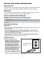
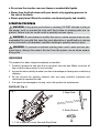
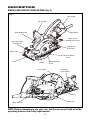
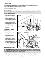
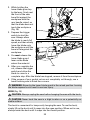
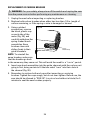
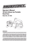
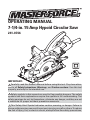
OPERATING MANUAL
7-1/4-in. 15 Amp Hypoid Circular Saw
241-0746
IMPORTANT :
Carefully read this Owner’s Manual before using this tool. Pay close attention to all Safety Instructions, Warnings, and Caution sections. Use this tool
properly, and only for its intended use.
Safety symbols in this manual are used to flag possible dangers. The safety
symbols and their explanations require the operator’s full understanding. The
safety warnings do not, by themselves, eliminate any danger, and they are not
a substitute for proper accident prevention measures.
This Safety Alert Symbol indicates caution, warning, or danger. Failure to
obey a safety warning can result in serious injury to yourself or others. To reduce
the risk of injury, fire, or electric shock, always follow the safety precautions.
TABLE OF CONTENTS
Rules for Safe Operation .............................................................................. Page 3
Unpacking ....................................................................................................... Page 8
Description ...................................................................................................... Page 9
Operation ......................................................................................................... Page 11
Maintenance................................................................................................... Page 23
Troubleshooting.............................................................................................. Page 27
Warranty.......................................................................................................... Page 28
PRODUCT SPECIFICATIONS
Input
15 Amps
Rating
120V, 60Hz AC
No-load Speed
4400RPM
Blade Diameter
7-1/4 in. (184mm)
Cutting Depth at 90°
2-3/8 in. (59.5mm)
Cutting Depth at 45°
1-11/16 in. (42.5mm)
Maximum Bevel Angle
51°
SAFETY SYMBOLS FOR YOUR TOOL
The label on your tool may include the following symbols.
V ......................................................Volts
A.......................................................Amps
Hz.....................................................Hertz
W......................................................Watts
min...................................................Minutes
...............................................Alternating current
..............................................Direct current
….............................................No-load speed
…...............................................Class II construction, Double Insulated
.../min...............................................Revolutions or Strokes per minute
.............................................. Indicates danger, warning or caution. It
means attention! Your safety is involved.
2
RULES FOR SAFE OPERATION
KNOW THE TOOL
To operate this tool, carefully read this Owner’s Manual and all labels affixed
to the saw before using. Keep this Manual available for future reference.
IMPORTANT
This tool should only be serviced by a qualified service technician. For more
information, call the toll-free helpline, at 1-866-917-4374.
READ ALL INSTRUCTIONS THOROUGHLY
GENERAL SAFETY RULES FOR ALL POWER TOOLS
WARNING! Read and understand all instructions. Failure to follow all instructions listed below may result in electric shock, fire and/or serious personal injury.
SAVE THESE INSTRUCTIONS.
Work Area
eep your work area clean and well lit. Cluttered benches and dark areas
●K
invite accidents.
o not operate power tools in explosive atmospheres, such as in the
●D
presence of flammable liquids, gases, or dust. Power tools create sparks
which may ignite the dust or fumes.
eep bystanders, children, and visitors away while operating a power
●K
tool. Distractions can cause you to lose control.
Electrical Safety
ouble insulated tools are
●D
equipped with a polarized plug
(one blade is wider than the other.)
This plug will fit in a polarized
Cover of Grounded
outlet only one way. If the plug
Outlet Box
does not fit fully in the outlet,
reverse the plug. If it still does not
fit, contact a qualified electrician
to install a polarized outlet. Do
not change the plug in any way.
Double insulation eliminates the
need for the three wire grounded
power cord and grounded power supply system.
3
● Avoid body contact with grounded surfaces such as pipes, radiators,
ranges and refrigerators. There is an increased risk of electric shock if
your body is grounded.
● Don’t expose power tools to rain or wet conditions. Water entering a
power tool will increase the risk of electric shock.
● Do not abuse the cord. Never use the cord to carry the tools or pull the
plug from an outlet. Keep cord away from heat, oil, sharp edges or moving
parts. Replace damaged cords immediately. Damaged cords increase the
risk of electric shock.
● When operating a power tool outside, use an outdoor extension cord marked
“W-A” or “W”. These cords are rated for outdoor use and reduce the risk of
electric shock. The following table shows the correct size to use, depending
on cord length and nameplate amperage rating of the tool. When in doubt, use
the next heavier gauge. Always use UL and CSA listed extension cords.
Recommended sizes of extension cords
Tool’s Ampere
rating
Volts
0-6
6-10
10-12
12-16
120V~
Total length of cord in feet Cord size in
A.W.G.(minimum)
25’
50’
100’
150’
18
16
16
14
18
16
14
12
16
16
14
12
14
12
Not Recommended
Personal Safety
tay alert, watch what you are doing and use common sense when
●S
operating a power tool. Do not use tool while tired or under the influence
of drugs, alcohol, or medication. A moment of inattention while operating
power tools may result in serious personal injury.
ress properly. Do not wear loose clothing or jewelry. Contain long hair.
●D
Keep your hair, clothing, and gloves away from moving parts. Loose
clothes, jewelry, or long hair can be caught in moving parts.
● Avoid accidental starting. Be sure switch is off before plugging in.
Carrying tools with your finger on the switch or plugging in tools that have
the switch on invites accidents.
● Remove adjusting keys or wrenches before turning the tool on. A wrench
or a key that is left attached to a rotating part of the tool may result in
personal injury.
● Do not overreach. Keep proper footing and balance at all times. Proper footing
4
and balance enables better control of the tool in unexpected situations.
se safety equipment. Always wear eye protection. Dust mask, non-skid safety
●U
shoes, hard hat, or hearing protection must be used for appropriate conditions.
efore connecting the tool to a power source (receptacle, outlet, etc.), be
●B
sure voltage supplied is the same as that specified on the nameplate of
the tool. A power source with voltage greater than that specified for the
tool can result in serious injury to the user – as well as damage to the tool.
Tool Use and Care
se clamps or other practical way to secure and support the workpiece
●U
to a stable platform. Holding the work by hand or against your body is
unstable and may lead to loss of control.
o not force tool. Use the correct tool for your application. The correct
●D
tool will do the job better and safer at the rate for which is designed.
o not use tool if switch does not turn it on or off. Any tool that cannot be
●D
controlled with the switch is dangerous and must be repaired.
isconnect the plug from the power source before making any
●D
adjustments, changing accessories, or storing the tool. Such preventive
safety measures reduce the risk of starting the tool accidentally.
tore idle tools out of reach of children and other untrained persons. Tools
●S
are dangerous in the hands of untrained users.
aintain tools with care. Keep cutting tools sharp and clean. Properly
●M
maintained tools, with sharp cutting edges are less likely to bind and are
easier to control.
heck for misalignment or binding of moving parts, breakage of parts,
●C
and any other condition that may affect the tools operation. If damaged,
have the tool serviced before using. Many accidents are caused by poorly
maintained tools.
se only accessories that are recommended by the manufacturer for
●U
your model. Accessories that may be suitable for one tool, may become
hazardous when used on another tool.
o not alter or misuse tool. These tools are precision built. Any alteration or
●D
modification not specified is misuse and may result in a dangerous condition.
Service
● T ool service must be performed only by qualified repair personnel. Service or
maintenance performed by unqualified personnel could result in a risk of injury.
hen servicing a tool, use only identical replacement parts. Follow
●W
instructions in the Maintenance section of this manual. Use of
5
unauthorized parts or failure to follow Maintenance Instructions may
create a risk of electric shock or injury.
Specific Safety Rules for circular saws
DANGER:Keep hands away from cutting area and blade. Keep your second hand on auxiliary handle, or motor housing. If both hands are holding the
saw, they cannot be cut by the blade.
● Keep your body positioned to either side of the saw blade, but not in line
with the saw blade. KICKBACK could cause the saw to jump backwards.
● Do not reach underneath the work. The guard can not protect you from the
blade below the work.
● Check lower guard for proper closing before each use. Do not operate saw
if lower guard does not move freely and close instantly. Never clamp or
tie the lower guard into the open position. If saw is accidentally dropped,
lower guard may be bent. Raise the lower guard with the Retracting Handle
and make sure it moves freely and does not touch the blade or any other
part, in all angles and depths of cut.
● Check the operation and condition of the lower guard spring. If the guard
and the spring are not operating properly, they must be serviced before
use. Lower guard may operate sluggishly due to damaged parts, gummy
deposits, or a buildup of debris.
● Lower guard should be retracted manually only for special cuts such as
“Pocket Cuts” and “Compound Cuts”. Raise lower guard by Retracting
Handle. As soon as blade enters the material, lower guard must be released.
For all other sawing, the lower guard should operate automatically.
● Always observe that the lower guard is covering the blade before placing
saw down on bench or floor. An unprotected, coasting blade will cause the
saw to walk backward, cutting whatever is in its path. Be aware of the time
it takes for the blade to stop after switch is released.
● NEVER hold piece being cut in your hands or across your leg. It is
important to support the work properly to minimize body exposure, blade
binding, or loss of control.
● Hold tool by insulated gripping surfaces when performing an operation
where the cutting tool may contact hidden wiring or its own cord. Contact
with a “live” wire will also make exposed metal parts of the tool “live” and
shock the operator.
● When ripping always use a rip fence or straight edge guide. This improves
the accuracy of cut and reduces the chance for blade binding.
● Always use blades with correct size and shape (diamond vs. round) arbor
6
holes. Blades that do not match the mounting hardware of the saw will run
eccentrically causing loss of control.
ever use damaged or incorrect blade washers or bolts. The blade
●N
washers and bolt were specially designed for your saw, for optimum
performance and safety of operation.
auses and operator prevention of kickback:
●C
-K
ickback is a sudden reaction to a pinched, bound or misaligned saw
blade, causing an uncontrolled saw to lift up and out of the workpiece
toward the operator.
-W
hen the blade is pinched or bound tightly by the kerf closing down, the blade
stalls and the motor reaction drives the unit rapidly back toward the operator.
- I f the blade becomes twisted or misaligned in the cut, the teeth at the
back edge of the blade can dig into the top surface of the wood causing
the blade to climb out of the kerf and jump back toward operator.
-K
ickback is the result of tool misuse and/or incorrect operating
procedures or conditions and can be avoided by taking proper
precautions as given below:
aintain a firm grip with both hands on the saw and position your body
●M
and arm to allow you to resist KICKBACK forces. KICKBACK forces can be
controlled by the operator, if proper precautions are taken.
hen blade is binding, or when interrupting a cut for any reason, release the
●W
trigger and hold the saw motionless in the material until the blade comes
to a complete stop. Never attempt to remove the saw from the work or pull
the saw backward while the blade is in motion or KICKBACK may occur.
Investigate and take corrective actions to eliminate the cause of blade binding.
hen restarting a saw in the workpiece, center the saw blade in the kerf and
●W
check that saw teeth are not engaged into the material. If saw blade is binding,
it may walk up or KICKBACK from the workpiece as the saw is restarted.
upport large panels to minimize the risk of blade pinching and
●S
KICKBACK. Large panels tend to sag under their own weight. Supports
must be placed under the panel on both sides near the line of cut and near
the edge of the panel.
o not use dull or damaged blade. Unsharpened or improperly set blades
●D
produce narrow kerf causing excessive friction, blade binding and KICKBACK.
lade depth and bevel adjusting locking levers must be tight and secure
●B
before making cut. If blade adjustment shifts while cutting, it may cause
binding and KICKBACK.
se extra caution when making a “Pocket Cut” into existing walls or other
●U
blind areas. The protruding blade may cut objects that can cause KICKBACK.
7
● Do not use the circular saw near fumes or combustible liquids.
● Never slow the blade down with your hands, or by applying pressure to
the side of the blade.
● Never apply force! Move the circular saw forward gently and steadily.
UNPACKING
WARNING: If any parts are broken or missing, DO NOT attempt to plug in
the power cord or operate the saw until the broken or missing parts are replaced. Failure to do so could result in possibly serious injury.
WARNING: Do not attempt to modify this saw or create accessories not recommended for use with this saw. Any such alteration or modification is misuse
and could result in a hazardous condition leading to possibly serious injury.
WARNING: To prevent accidental starting that could cause serious personal injury, always disconnect the tool from the power source when assembling parts.
UNPACKING
This product has been shipped completely assembled.
1. Carefully remove the tool and the accessories from the box. Make sure that all
items listed in the packing list are included.
2. Inspect the tool carefully to make sure that no breakage or damage occurred during
shipping.
3. Do not discard the packing material until you have carefully inspected and
satisfactorily operated the tool.
4. If any parts are damaged or missing, return the product for replacement.
PARTS LIST (Fig. 1)
Fig. 1
2. Edge Guide
3. Blade Wrench
1. 7-1/4-in Hypoid Circular Saw with Saw Blade
8
DESCRIPTION
KNOW YOUR HYPOID CIRCULAR SAW (Fig. 2)
Fig. 2
Rear Handle
Front Handle
Upper Blade Guard
Trigger Switch
Depth-of-Cut
Adjustment Lever
Bevel Adjustment
Locking Lever
Lower Blade
Guard Lever
Bevel Scale
Lower Blade
Guard
Base
Blade
Front Handle
Spindle Clamping
Screw
Edge Guide
Locking Knob
Base
Motor Housing
Rafter Hook
NOTE: Before attempting to use your saw, familiarize yourself with all of the
operating features and safety requirements.
9
Your hypoid circular saw has a precision-built electric motor and it should only
be connected to a 120-volt, 60-Hz AC ONLY power supply (normal household
current). DO NOT operate on direct current (DC). This large voltage drop will
cause a loss of power and the motor will overheat. If the saw does not operate
when plugged into correct 120-volt, 60-Hz AC ONLY outlet, check the power
supply. The saw has a 8-ft, 2-wire power cord (no adapter needed).
This Hypoid Circular Saw has the following features:
• 15 Amp, 4400 RPM (no-load speed) motor provides power and torque for
fast, sure cuts in wood, plywood, hardboard, and wood-base materials.
• Quick depth-of-cut adjustments with maximum depth of cut: 2-3/8-in. thick
at 90°; 1-11/16-in. thick at 45°
• Easy-to-read bevel-cut scale adjusts from 0° to 51° bevel capacity.
• Heavy duty, lightweight, magnesium upper and lower blade guards for
extra strength and durability.
• Extended-length trigger switch for maximum control and comfort.
• Aluminum base provides stability for maximum control during sawing
applications.
• Rear handle and front assist handle for positive gripping, control, balance,
and comfort.
• Includes 24-tooth, carbide-tipped steel, blade for fast, smooth cuts.
• Front-mounted spindle lock for easy blade changes.
• Built-in sawdust ejection chute helps direct dust and chips away from the
operator.
• Permanently lubricated ball bearings throughout for smooth operation and
long motor life.
• Durable, machined hypoid gearing for efficient power transmission.
10
OPERATION
WARNING: The maximum blade capacity of your saw is 7-1/4 inches. Any
blade larger than 7-1/4 inch will come in contact with the blade guards. Never
use a blade that is so thick that it prevents the outer blade washer from engaging with the flat side of the spindle. Blades that are too large or too thick can
result in an accident causing serious injury.
SAW BLADES
All saw blades need to be kept clean, sharp, and properly set in order to cut
efficiently. Using a dull blade places a heavy load on the saw and increases
the danger of kickback. Keep extra blades on hand, so sharp blades are
always available. Gum and wood pitch that have hardened on the blade will
slow the saw. Use gum and pitch remover, hot water, or kerosene to remove
these substances. Do not use gasoline.
BLADE GUARD SYSTEM (Fig. 3)
The lower blade guard is
Fig. 3
there for your protection and
Lower Blade Guard level
safety. It should never be
is in UP position when
altered for any reason. If the making a cut
lower blade guard becomes
damaged or begins to
return slowly or sluggishly,
do not operate your saw
until the damaged part has
been repaired or replaced.
Always leave the guard in its
correct operating position
1/4 in. or less of the Blade is exposed on
when using the saw.
the underside of the workpiece
Lower Blade Guard
retracts automatically
when cut is being made
DANGER: When sawing through a workpiece, the lower blade guard does
not cover the blade on the underside of the workpiece. Keep hands and fingers away from the cutting area. If any part of your body comes in contact with
the moving blade, serious injury will result.
CAUTION: Never use the saw when the lower blade guard is not operating
properly. The lower blade guard should be checked for correct operation before each use. If you drop your saw, check the lower blade guard and bumper
for damage at all depth settings before using.
NOTE: The lower blade guard is operating properly when it moves freely
and then readily returns to the closed position. If, for any reason, your lower
blade guard and bumper do not close freely, take the saw to your nearest
Repair Center for service before using it.
11
KICKBACK…WHAT CAUSES IT AND WAYS TO HELP PREVENT IT
Kickback Causes
• K
ickback is a sudden
reaction to a pinched,
bound, or misaligned
saw blade, which
can cause the saw to
lift up and out of the
workpiece and toward
the operator.
• W
hen the blade is
pinched or bound
tightly by the kerf
closing down, the
blade stalls and the
motor reaction drives
the unit rapidly back
towards the operator.
• I f the blade becomes
twisted or misaligned
in the cut, the teeth
at the rear edge of
the blade can dig into
the top surface of the
wood. This causes the
blade to climb out of
the kerf and jump back
towards the operator.
Fig. 4
Right
Fig. 4a
Wrong
• Sawing into knots or nails in the workpiece can cause kickback.
• Sawing into wet or warped lumber can cause kickback (Fig. 4a).
• F orcing a cut, or not supporting the workpiece correctly can cause
kickback (Fig. 4a).
• Tool misuse and/or incorrect operating procedures or conditions can
cause kickback.
12
Ways to Help Prevent Kickback
DANGER: Always release the trigger switch immediately if the blade binds
or the saw stalls. Kickback could cause you to lose control of the saw. Loss of
control can lead to serious injury.
1. Always maintain a
firm grip with both
hands on the saw (Fig.
5) and position your
body and arms to allow
you to resist kickback
forces. The operator
can control kickback
forces if the proper
precautions are taken.
Fig. 5
2. If the blade is binding
or when you are
interrupting a cut for
any reason, always
release the trigger and hold the saw motionless in the material until the
blade comes to a complete stop. Never attempt to remove the saw from
the workpiece or pull the saw backward while the blade is in motion, or
kickback may occur. Check and take corrective action to eliminate the
cause of blade binding.
3. Inspect the workpiece for knots or nails before cutting. Never saw into a
knot or nail.
4. Do not cut warped or wet lumber (Fig. 4a).
5. Always support large panels to minimize the risk of blade pinching and
kickback. Large panels tend to sag under their own weight (Fig. 4a).
Supports must be placed under the panel: one near the line of cut and
one near the edge of the panel (Fig. 4).
6. When restarting the saw in the workpiece, center the blade in the
kerf and check to be sure that the saw teeth are not engaged into the
material. If the saw blade is binding, it may walk up or kick back from the
workpiece when the saw is restarted.
7. Do not use a dull or damaged blade. Unsharpened, improperly set,
or gummed-up blades produce narrow kerfs, which cause excessive
friction, blade binding, and Kickback.
13
8. Keep the blade at the correct depth setting. The depth setting should
not exceed 1/4 inch below the material being cut (Fig. 6). Be sure that
the blade depth and adjusting locking levers are tight and secure before
making a cut. If blade adjustment shifts while cutting, it may cause
binding and Kickback.
Fig. 6
Correct Blade Depth
Blade is Set Too Deep
KICKBACK
9. Use extra caution when making a “Pocket Cut” into existing walls or
other blind areas. The protruding blade may cut objects that can cause
Kickback.
STARTING/STOPPING THE SAW
To start the saw: Depress
the trigger switch (Fig. 7).
Fig. 7
Trigger Switch
Always allow the blade to
reach full speed, and then
guide the saw into the
workpiece.
To stop the saw: Release
the trigger switch.
After you release the
trigger switch, allow
the blade to come to a
complete stop. Do not
remove the saw from the
workpiece while the blade is moving.
14
MAKING DEPTH-OF-CUT ADJUSTMENTS
Always use the correct
Fig. 8
blade-depth setting. The
correct blade-depth setting Depth-of-cut
adjustment
for all cuts should not be
lever
more than 1/4-inch deeper
than the material being cut.
Increased cutting depth
will increase the chance
of kickback and cause the
cut to be rough. Your saw
is equipped with a depthof-cut scale that provides
increased depth-of-cut
accuracy. The depth-of-cut
scale is located on the left side of the bracket (Fig 8).
Depth-ofcut scale
TO SET THE BLADE DEPTH
WARNING: Always unplug the saw before making any adjustments.
Failure to unplug the saw could result in accidental starting, which can
cause serious personal injury.
1. Unplug the saw.
2. Raise the depth-of-cut adjustment lever to loosen the base (Fig. 8).
3. Determine the desired depth of cut (see page 19).
4. Locate the depth-of-cut scale on the left side of the bracket (Fig. 8).
5. Hold the base of the saw flat against the edge of the workpiece, and then
raise or lower the saw until the indicator aligns with the desired depth-ofcut mark.
6. Tighten the depth-of-cut adjustment lever.
STARTING A CUT
WARNING: Always securely clamp and support the workpiece. Always
maintain proper control of the saw. Failure to clamp and support the workpiece and loss of control of the saw could result in serious injury.
WARNING: Always maintain proper control of the saw to make sawing
safer and easier. Loss of control of the saw could cause an accident resulting
in possibly serious injury
15
1. Always use your
saw with your hands
positioned correctly:
with one hand
operating the trigger
switch and the other
on the front assist
handle (Fig. 9). Never
use the saw with your
hands positioned as
shown in Fig. 10.
Fig. 9
To Help Maintain Control:
Always support the
workpiece near the cut.
Always support the
workpiece so the cut will
be on your right.
Fig. 10
Always clamp the
workpiece so it will not
move during the cut.
Place the workpiece with
the good side down.
NOTE: The good side of the
workpiece is the side where
appearance is important.
2. Before starting a cut,
draw a guideline along the desired line of cut, then place the front edge of
the saw base on that part of the workpiece that is solidly supported (Fig. 9).
Never place the saw on the part of the workpiece that will fall off when the
cut is made.
Always keep the cord away from the cutting area. Always place the cord so
that it does not hang up on the workpiece when making a cut.
3. Hold the saw firmly with both hands (Fig. 9).
WARNING: If the cord hangs up on the workpiece during a cut, release the
trigger switch immediately. To avoid injury, unplug the saw and move the cord
to prevent it from hanging up again.
DANGER! Using the saw with a damaged cord could result in serious injury or death. If the cord has been damaged, have it replaced before using the
saw again.
16
4. Depress the trigger switch to start the saw.
5. Always let the blade reach full speed before you begin the cut into the
workpiece.
6. When making a cut, always use steady, even pressure. Forcing the saw
causes rough cuts and could shorten the life of the saw or cause Kickback.
7. After completing your cut, release the trigger switch and allow the blade
to come to a complete stop. Do not remove the saw from the workpiece
while the blade is moving.
DANGER! When sawing through a workpiece, the lower blade guard does
not cover the blade on the underside of the workpiece (Fig. 3). Always keep
your hands and fingers away from the cutting area. Any part of your body coming in contact with the moving blade will result in serious injury.
MAKING CROSS CUTS AND RIP CUTS
WARNING: Always securely clamp and support the workpiece. Always
maintain proper control of the saw. Failure to clamp and support the workpiece and loss of control of the saw could result in serious injury.
WARNING: Always maintain proper control of the saw to make sawing
safer and easier. Loss of control of the saw could cause an accident resulting
in possibly serious injury.
1. Always use your
saw with your hands
positioned correctly
(Fig. 11).
Fig. 11
2. When making cross or
rip cuts, align your line
of cut with the left side
of the notch by the 0°
indicator. (Fig. 11a).
3. Since the thicknesses of
blades vary, make a trial
cut in scrap material
along the guideline to
determine how much, if any, you should offset the blade from the guideline to
allow for the kerf of the blade and make an accurate cut.
INTEGRATED CROSSCUT RULER
A ruler for measuring cross cuts is marked along the front of the saw base.
17
MAKING RIP CUTS
Fig. 11a
Line of Cut
Always use a guide when
making long or wide rip cuts
with your saw. You can use
either a straight edge or use
the edge guide that was
included with your saw.
0o Indicator
USING A STRAIGHT EDGE
WARNING: Always securely clamp and support
the workpiece. Always
maintain proper control of
the saw. Failure to clamp
and support the workpiece, combined with loss
of control of the saw, could
result in serious injury.
Fig. 12
You can make an efficient
rip guide by clamping
a straight edge to your
workpiece.
1. Always allow the blade
to reach full speed,
Straight Edge
and then carefully
guide the saw into the workpiece. Do not bind the blade in the cut.
2. Carefully guide the saw along the straight edge for a straight rip cut (Fig. 12).
3. Push the saw forward slowly enough that the blade is not laboring.
EDGE GUIDE
The saw comes with an edge guide. It allows you to make accurate parallel
cuts. The edge guide attaches to the saw base and is secured in place with a
turn screw.
USING THE EDGE GUIDE
Always use a guide when making long or wide rip cuts with your saw. You can
use either a straight edge or use the edge guide that was included with the saw.
18
WARNING: Always unplug the saw before making any adjustments. Failure to unplug the saw could result in accidental starting, which can cause
serious personal injury.
1. Unplug the saw from
the power source.
Fig. 13
2. Position the edge
guide so that the ruler
side of the arm is
facing up. Slide the
arm of the edge guide
through the mounting
slots at the front of the
saw base (Fig 13).
3. Adjust the edge guide
to the desired width
of cut.
Edge Guide
4. Tighten the edge-guide lock knob.
When using the edge guide, position the face of the edge guide firmly against
the edge of the workpiece. This will help to make a true cut without binding
the blade. The edge of the workpiece must be straight for the cut to be
straight. Use caution to prevent the blade from binding in the cut.
SETTING THE BEVEL ANGLE
WARNING: Always unplug the saw before making any adjustments. Failure to unplug the saw could result in accidental starting, which can cause
serious personal injury.
1. Unplug the saw.
Fig. 14
2. Loosen bevel
adjustment lever (Fig.14).
3. Raise the motorhousing end of the saw
until the desired angle
setting is indicated on
the bevel scale.
4. Tighten the bevel
adjustment lever
securely.
Bevel Pointer
Bevel Adjustment Lever
19
MAKING BEVEL CUTS
WARNING: Always securely clamp and support the workpiece. Always
maintain proper control of the saw. Failure to clamp and support the workpiece and loss of control of saw could result in serious injury.
1. Your saw can be
adjusted to bevel cut
at any angle between
0° and 51°. When
making 45° bevel cuts,
there is a notch in the
saw base to help you
line up the blade with
the line of cut (Fig. 15).
2. Align your line of cut
with the left side of
the notch by the 45°
indicator when making
45° bevel cuts.
3. Since blade thicknesses
vary and different
angles require different
settings, make a trial
cut in scrap material
along the guideline to
determine how much,
if any, you should offset
the blade from the
guideline to allow for
the kerf of the blade.
Fig. 15
Line of Cut
45° Indicator
Fig. 15a
4. When making a bevel
cut, hold the saw
firmly with both hands (Fig. 15a).
5. Rest the front edge of the saw’s base on the workpiece, and then depress
the trigger switch to start the saw. Always allow the blade to reach full
speed, then guide the saw into the workpiece.
6. After completing your cut, release the trigger switch and allow the blade
to come to a complete stop in the cut. Do not remove the saw from the
workpiece while the blade is moving. It will damage your bevel cut and
cause kickback.
20
0° BEVEL STOP
The saw has a 0° bevel stop that has been factory adjusted to assure a 0°
angle of the saw blade when making 90°cuts.
TO CHECK 0° BEVEL STOP
WARNING: Always unplug the saw before making any adjustments. Failure to unplug the saw could result in accidental starting, which can cause
serious personal injury.
1. Unplug the saw from
the power source.
Fig. 16
0° bevel stop adjustment screw
2. Place the saw in an
upside-down position
on a workbench.
3. Using a carpenter’s
square, check that the
saw blade is square
to the base of the saw
(Fig 16).
TO ADJUST 0° BEVEL
STOP (Fig. 17)
1. Unplug the saw from
the power source.
Bevel adjustment knob
Fig. 17
0° bevel-stop
adjusting screw
2. Loosen the beveladjustment knob.
3. Locate the 0° bevelstop adjusting screw
4. Using a hex key, turn the
0° bevel-stop adjusting
screw until it is square
with the saw blade.
MAKING POCKET CUTS
WARNING: Always adjust the bevel setting to zero before making a pocket
cut. Attempting a pocket-cut at any other setting can result in a loss of control
of the saw, which can result in serious injury.
1. Adjust the bevel setting to zero, set the blade to the correct blade depth
setting, then use the lower blade guard lever to swing the guard up.
21
2. While holding the
lower blade guard up
by the lever, firmly rest
the front of the saw
base flat against the
workpiece with the
rear handle raised, so
that the blade does not
touch the workpiece
(Fig. 18).
3. Depress the trigger
switch to start the
saw. Always allow
the blade to reach full
speed, and then slowly
lower the blade onto
the workpiece until the
base is flat against the
workpiece.
Fig. 18
Fig. 19
4. You must release the
lower blade guard
lever as the blade
enters the material.
Hook
5. After you complete the
cut, release the trigger
switch and allow the
blade to come to a
complete stop. After the blade has stopped, remove it from the workpiece.
6. If the corners of your pocket cut are not completely cut through, use a
hand finishing saw to finish the corners.
WARNING: Never tie the lower blade guard in the raised position. Leaving
the blade exposed could result in serious injury.
HOOK (Fig. 19)
CAUTION: Always unplug the saw before hanging the saw with the hook.
CAUTION: Never hook the saw in a high location or on a potentially unstable surface.
The hook is convenient for temporarily hanging the saw. To use the hook,
simply lift up the hook until it snaps into the open position. When not in use,
always lower the hook until it snaps into the closed position.
22
MAINTENANCE
WARNING: To ensure safety and reliability, all repairs should be performed
by a qualified service technician.
WARNING: For your safety, always turn off the switch and unplug the hypoid circular saw from the power source before performing any maintenance
or cleaning.
It has been found that electric tools are subject to accelerated wear and
possible premature failure when they are used to work on fiberglass boats
and sports cars, wallboard, spackling compounds, or plaster. The chips
and grindings from these materials are highly abrasive to electrical tool
parts, such as bearings, brushes, commutators, etc. Consequently, it is not
recommended that this tool be used for extended work on any fiberglass
material, wallboard, spackling compound, or plaster. During use on these
materials, it is extremely important that the tool is cleaned frequently by
blowing with an air jet.
WARNING: Always wear safety goggles or safety glasses with side shields
during power-tool operations, or when blowing dust. If operation is dusty, also
wear a dust mask.
ROUTINE MAINTENANCE
WARNING: Do not at any time let brake fluids, gasoline, petroleum-based
products, penetrating oils, etc. come in contact with plastic parts. Chemicals can
damage, weaken, or destroy plastic, which may result in serious personal injury.
Periodic maintenance allows for long life and trouble-free operation. A
cleaning, lubrication and maintenance schedule should be maintained. As a
common preventive maintenance practice, follow these recommended steps:
• W
hen work has been completed, clean the tool to allow smooth
functioning of the tool over time.
• U
se clean, damp cloths to wipe the tool.
• Check the state of all electrical cables.
• K
eep the motor’s air openings free from oil, grease, and sawdust or
woodchips, and store the tool in a dry place.
• B
e certain that all moving parts are well lubricated, particularly after
lengthy exposure to damp and/or dirty conditions.
23
REPLACEMENT OF CARBON BRUSHES
WARNING: For your safety, always turn off the switch and unplug the saw
from the power source before performing any maintenance or cleaning.
1. U
nplug the saw before inspecting or replacing brushes.
2. R
eplace both carbon brushes when either has less than 1/4-in. length of
carbon remaining, or if the spring or wire is damaged or burned.
3. U
sing a slotted
screwdriver, remove
the black, plastic cap
on each side of the
motor (Fig. 20), and
carefully withdraw the
spring-loaded brush
assemblies. Keep
brushes clean and
sliding freely in their
guide channels.
Fig. 20
Plastic Cap
NOTE: To reinstall the
same brushes, make sure
that the brushes go back
in the same way they came out. This will avoid the need for a “run-in” period.
4. I nsert new brush assemblies into the guide channels with the carbon part
going in first, being certain to fit the two metal “ears” into their slots in
the channel (Fig. 20).
5. R
emember to replace both end caps after inspecting or servicing
brushes. Tighten the caps snugly, but do not over-tighten. Before use, the
saw should be allowed to “RUN IN” (run at no load without a blade) for 5
minutes to seat the new brushes properly.
24
CHANGING THE BLADE
WARNING: Be sure to wear protective work gloves while handling a saw
blade. The blade can injure unprotected hands.
1. Unplug the saw from the power source.
WARNING: To prevent personal injury, ALWAYS disconnect the plug from
power source BEFORE assembling parts, making adjustments or changing
blades.
2. Place the saw, on its
side, on a flat surface.
3. Loosen the depth-ofcut adjustment lever,
raise the saw up all the
way, and tighten the
lever. This gives you
easier access to the
blade mounting area.
4. Place the saw upright
on its base on a flat
surface.
5. To loosen the spindleclamping screw “A,”
Fig. 21, depress the
spindle-lock button
(Fig. 21a). Insert the
blade wrench in the
spindle clamping
screw “A.” Move the
wrench in and out
slightly until you feel
the spindle lock button
depress further, which
locks the blade in
position so the spindle
clamping screw can
be removed.
Fig. 21
Outer “D” Washer
“A” Spindle
Clamping Screw
Blade Rotation teeth
point up at front
Fig. 21a
Spindle Lock Button
6. Keeping the spindle lock button firmly depressed, turn the wrench
clockwise to remove the spindle-clamping screw.
7. Use the blade-guard lever to raise the lower blade guard and hold it in the
raised position for the next steps.
25
8. C
ompletely remove the spindle-clamping screw “A,” the outer “D”
washer, and the blade (see Fig. 21).
9. T he remaining washer is the inner bushing washer that fits around the
spindle shaft; it does not need to be removed.
10. Put a drop of oil onto the inner bushing washer and outer “D” washer
where they will touch the blade.
11. Place the new saw blade inside the lower blade guard, onto the spindle
shaft, and against the inner bushing.
NOTE: The teeth of the blade should point upward at the front of the saw. The
printed side will face outward when using the blade included with the saw.
12. Replace the “D” washer.
13. Firmly hold down the spindle lock button as you replace the spindle screw
and hand tighten it in a counterclockwise direction. Then use the blade
wrench to securely tighten the spindle clamping screw.
LUBRICATION
All of the bearings in this tool are lubricated with a sufficient amount of highgrade lubricant for the life of the tool under normal operating conditions.
Therefore, no further lubrication is required.
26
TROUBLE SHOOTING
If the blade does not follow a straight line:
• T eeth are dull. This is caused by hitting a hard object such as a nail, and
dulling the teeth on one side. The blade tends to cut to the side with the
sharpest teeth.
• Base is out of line or bent.
• B
lade is bent.
• Edge guide or straight edge is not being used.
If the blade binds or smokes from friction:
• Blade is dull.
• B
lade is on backwards.
• Blade is bent.
• Workpiece is not properly supported.
• I ncorrect blade is being used.
27
WARRANTY
If, during normal use, this MASTERFORCE™ power tool breaks or fails due
to a defect in material or workmanship within three years from the date of
original purchase, simply bring this tool and its sales receipt back to your
nearest MENARDS® retail store for a free equivalent replacement within
those three years.
The warranty:
(1) excludes expendable parts including but not limited to blades, bits, light
bulbs, and/or batteries;
(2) shall be void if this tool is used for commercial or rental purposes; and
(3) does not cover any losses, injuries to persons/properties, or costs. This
warranty does give you specific legal rights and you may have other
rights, which vary from state to state.
*SAVE YOUR RECEIPTS. Your warranty is void without them. For help, please
call to our customer center, toll free number: 1-866-917-4374.
28