1
Owner's Manual
7-1/4 in. CIRCULAR SAW
Double Insulated
Model Nos.
315.108400
315.108410
Save this manual for
future reference.
CAUTION:
• Safety
• Features
•
•
•
•
Read and follow
all Safety Rules and Operating
Instructions before first use of
this product.
Customer
Help Line: 1-800-932-3188
Sears, Roebuck
and Co., Hoffman
Estates,
IL 60179
Visit the Craftsman web page: www.sears.com/craftsman
972000-823
10-01
USA
Assembly
Operation
Maintenance
Parts List
TABLE
OF CONTENTS
•
Table of Contents ...............................................................................................................................................
•
General Safety Rules .....................................................................................................................................
2-3
•
Specific Safety Rules and/or Symbols ............................................................................................................
3-6
•
Features .........................................................................................................................................................
7-8
•
Assembly ......................................................................................................................................................
9-10
•
Operation ....................................................................................................................................................
11-18
•
Maintenance ...............................................................................................................................................
18-19
•
Accessories
.....................................................................................................................................................
19
•
Exploded View and Repair Parts List .........................................................................................................
20-21
•
Parts Ordering/Service
_i
...................................................................................................................................
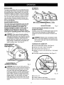
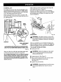
When operating a power tool outside, use an
outdoor extension cord marked "W-A" or "W".
These cords are rated for outdoor use and reduce
the risk of electric shock.
INSTRUCTIONS
Work Area
•
Keep your work area clean and well lit. Cluttered benches and dark areas invite accidents.
Do not operate power tools in explosive
atmospheres, such as in the presence of
flammable liquids, gases, or dust. Power tools
may create sparks which may ignite the dust or
fumes.
•
Keep bystanders, children, and visitors away
while operating a power tool. Distractions can
cause you to lose control.
Electrical
•
Personal
Safety
•
Stay alert, watch what you are doing and use
common sense when operating a power tool.
Do not use tool while tired or under the influence of drugs, alcohol, or medication. A moment of inattention while operating power tools
may result in serious personal injury.
•
Dress properly. Do not wear loose clothing or
jewelry. Contain long hair. Keep your hair,
clothing, and gloves away from moving parts.
Loose clothes, jewelry, or long hair can be caught
in moving parts.
•
Avoid accidental starting. Be sure switch is off
before plugging in. Carrying tools with your
finger on the switch or plugging in tools that have
the switch on, invites accidents.
Safety
Double insulated tools are equipped with a
polarized plug (one blade is wider than the
other). This plug will fit in a polarized outlet
only one way. If the plug does not fit fully in the
outlet, reverse the plug. If it still does not fit,
contact a qualified electrician to install a
polarized outlet. Do not change the plug in any
way. Double insulation [] eliminates the need for
the three-wire grounded power cord and grounded
power supply system.
22
Keep cord away from heat, oil, sharp edges, or
moving parts. Replace damaged cords immediately. Damaged cords increase the risk of electric
shock,
WARNING: Read and understand all instructions. Failure to follow all instructions listed
below may result in electric shock, fire and/or
serious personal injury.
SAVE THESE
2
Remove adjusting keys or wrenches before
turning the tool on. A wrench or a key that is left
attached to a rotating part of the tool may result in
personal injury.
•
Avoid body contact with grounded surfaces,
such as pipes, radiators, ranges, and refrigerators. There is an increased risk of electric shock if
your body is grounded.
Do not overreach. Keep proper footing and
balance at all times. Proper footing and balance
enables better control of the tool in unexpected
situations.
•
Don't expose power tools to rain or wet conditions. Water entering a power tool will increase
the risk of electric shock.
•
Do not abuse the cord. Never use the cord to
carry the tools or pull the plug from an outlet.
Use safety equipment. Always wear eye protection. Dust mask, nonskid safety shoes, hard hat,
or hearing protection must be used for appropriate
conditions.
Tool Use and Care
•
•
Use clamps or another practical way to secure
and support the workpiece to a stable platform. Holding the work by hand or against your
body is unstable and may lead to loss of control.
•
Do not force tool. Use the correct tool for your
application. The correct tool will do the job better
and safer at the rate for which it is designed.
•
Do not use tool if switch does not turn it on or
off. Any tool that cannot be controlled with the
switch is dangerous and must be repaired.
•
Store idle tools out of the reach of children and
other untrained persons. Tools are dangerous in
the hands of untrained users.
•
Maintain tools with care. Keep cutting tools
sharp and clean. Properly maintained tools with
sharp cutting edges are less likely to bind and are
easier to control.
Specific
•
Use only accessories that are recommended
by the manufacturer for your model. Accessories that may be suitable for one tool, may become
hazardous when used on another tool.
Service
Disconnect the plug from power source before
making any adjustments, changing accessories, or storing the tool. Such preventive safety
measures reduce the risk of starting the tool
accidentally.
•
Safety Rules for Circular
Saws
DANGER! Keep hands away from cutting
area and blade. Keep your second hand on
Prevention
•
(See "Causes
guard cannot protect
below the work.
•
Check
When servicing a tool, use only identical
replacement parts. Follow instructions in the
Maintenance section of this manual. Use of
unauthorized parts or failure to follow Maintenance
Instructions may create a risk of electric shock or
injury.
spring are not operating properly, they
must be serviced before use. Lower guard
may operate sluggishly due to damaged
parts, gummy deposits, or a buildup of
debris.
and Operator
the work. The
Lower guard should be retracted manually
only for special cuts, such as "Pocket
Cuts" and "Compound
Cuts." Raise lower
you from the blade
lower guard for proper
•
Check the operation and condition of the
lower guard spring. If the guard and the
of Kickback.")
Do not reach underneath
Tool service must be performed only by qualified repair personnel. Service or maintenance
performed by unqualified personnel could result in
a risk of injury.
retracting handle. Make sure it moves freely
and does not touch the blade or any other
part, in all angles and depths of cut.
Keep your body positioned to either side
of the saw blade, but not in line with the
saw blade. Kickback could cause the saw to
jump backwards.
•
is accidentally
dropped, lower guard may be
bent. Raise the lower guard with the
the auxiliary handle or motor housing. If
both hands are holding the saw, they cannot
be cut by the blade.
•
Check for misalignment or binding of moving
pads, breakage of parts, and any other condition that may affect the tool's operation. If
damaged, have the tool serviced before using.
Many accidents are caused by poorly maintained
tools.
closing
guard by retracting handle. As soon as
blade enters the material, lower guard
before each use. Do not operate saw if
lower guard does not move freely and
close instantly. Never clamp or tie the
lower guard into the open position. If saw
must be released. For all other sawing, the
lower guard should operate automatically.
3
Specific
Safety Rules for Circular
causing the blade to climb out of the kerf and
jump back toward the operator.
Saws
(continued)
•
•
Always observe that the lower guard is
covering the blade before placing saw
down on bench or floor. An unprotected,
coasting blade will cause the saw to walk
backwards, cutting whatever is in its path. Be
aware of the time it takes for the blade to
•
•
Hold
•
or loss of control.
tool by insulated
gripping
surface
with correct
•
•
•
loss of control.
Never use damaged or incorrect blade
washers or bolts. The blade washers and
bolts were specially designed for your saw for
optimum performance
and safety of
operation.
Causes
•
•
•
and Operator
Prevention
When restarting a saw in the workpiece,
center the saw blade in the kerf and check
that saw teeth are not engaged into the
material. If saw blade is binding, it may walk
up or KICKBACK from the workpiece as the
saw is restarted.
size and
shape (diamond vs. round) arbor holes.
Blades that do not match the mounting
hardware of the saw will run eccentrically,
causing
in
blade binding.
for blade binding.
use blades
release
KICKBACK
may occur. Investigate and take
corrective actions to eliminate the cause of
When ripping, always use a rip fence or
straight edge guide. This improves the
accuracy of the cut and reduces the chance
Always
When blade is binding, or when
interrupting
a cut for any reason,
complete stop. Never attempt to remove
the saw from the work or pull the saw
backward while the blade is in motion, or
also make exposed metal parts of the tool
"live" and shock the operator.
•
Maintain a firm grip with both hands on
the saw and position your body and arm
to allow you to resist KICKBACK
forces.
the trigger and hold the saw motionless
the material until the blade comes to a
when performing an operation where the
cutting tool may contact hidden wiring or
its own cord. Contact with a "live" wire will
•
and/or
KICKBACK forces can be controlled by the
operator, if proper precautions are taken.
NEVER hold piece being cut in your hands
or across your leg. It is important to support
the work properly to minimize body exposure,
blade binding,
is the result of tool misuse
incorrect operating procedures or conditions
and can be avoided by taking proper
precautions,
as given below:
stop after switch is released.
•
Kickback
Support large panels to minimize
of blade pinching and KICKBACK.
panels tend to sag under their own
Supports must be placed under the
both sides, near the line of cut and
the risk
Large
weight.
panel on
near the
edge of the panel.
•
of Kickback
Kickback is a sudden reaction to a pinched,
bound, or misaligned saw blade, causing an
uncontrolled
saw to lift up and out of the
workpiece toward the operator.
Do not use dull or damaged blade.
Unsharpened
or improperly set blades
produce narrow kerf which causes excessive
friction,
•
When the blade is pinched or bound tightly
by the kerf closing down, the blade stalls and
the motor reaction drives the unit rapidly back
toward the operator.
blade binding
and KICKBACK.
Blade depth and bevel adjusting locking
levers must be tight and secure before
making cut. If blade adjustment shifts while
cutting, it may cause binding and KICKBACK.
•
If the blade becomes twisted or misaligned
in
the cut, the teeth at the back edge of the
blade can dig into the top surface of the wood
4
Use extra caution when making a "Pocket
Cut" into existing walls or other blind
areas. The protruding blade may cut objects
that can cause KICKBACK.
Hold tool by insulated gripping surfaces when performing an operation where the cutting tool may contact hidden wiring or its cord. Contact with a "live" wire will make exposed metal parts of the tool "live" and
shock the operator.
Additional
•
Rules For Safe Operation
•
Make sure your extension cord is in good
condition. When using an extension cord, be
sure to use one heavy enough to carry the
current your product will draw. A wire gage
size (A.W.G.) of at least 16 is recommended for
an extension cord 100 feet or less in length. A
cord exceeding 100 feet is not recommended.
If in doubt, use the next heavier gage. The
smaller the gage number, the heavier the cord.
An undersized cord will cause a drop in line
voltage resulting in loss of power and overheating.
•
Inspect for and remove all nails from lumber
before sawing. Following this rule will reduce the
risk of serious personal injury.
•
Drugs, alcohol, medication. Do not operate tool
while under the influence of drugs, alcohol, or
any medication. Followingthis rule will reduce the
risk of electric shock, fire, or serious personal injury.
•
Save these instructions.
Refer to them frequently and use them to instruct others who
may use this tool. If you loan someone this
tool, loan them these instructions also.
Know your power tool. Read operator's manual
carefully. Learn its applications and limitations,
as well as the specific potential hazards
related to this tool. Following this rule will reduce
the risk of electric shock, fire, or serious injury.
Always wear safety glasses. Everyday eyeglasses have only impact-resistant lenses;
they are NOT safety glasses. Following this rule
will reduce the dsk of serious personal injury.
•
Protect your lungs. Wear a face or dust mask if
the operation is dusty. Following this rule will
reduce the risk of serious personal injury.
Protect your hearing. Wear hearing protection
during extended periods of operation. Following
this rule will reduce the risk of serious personal
injury.
Inspect tool cords periodically and, if damaged, have repaired at your nearest Factory
Service Center or other Authorized Service
Organization. Constantly stay aware of cord
location. Following this rule will reduce the risk of
electric shock or fire.
Check damaged parts. Before further use of
the tool, a guard or other part that is damaged
should be carefully checked to determine that
it will operate properly and perform its intended function. Check for alignment of moving parts, binding of moving parts, breakage of
parts, mounting, and any other conditions that
may affect its operation. A guard or other part
that is damaged should be properly repaired or
replaced by an authorized service center.
Following this rule will reduce the risk of shock,
fire, or serious injury.
Do not abuse cord. Never carry the tool by the
cord or yank it to disconnect it from the receptacle. Keep cord away from heat, oil, and sharp
edges. Following this rule will reduce the risk of
electric shock or fire.
,_
_I, WARNING"
Some dust created by power
sanding, sawing, grinding, drilling, and other
construction activities contains chemicals known
to cause cancer, birth defects or other reproductive harm. Some examples of these chemicals
are:
• lead from lead-based
paints,
• crystalline silica from bricks and cement
and other masonry products, and
• arsenic and chromium from chemicallytreated lumber.
Your risk from these exposures varies,
depending on how often you do this type of
work. To reduce your exposure to these
chemicals: work in a well ventilated area, and
work with approved safety equipment, such as
those dust masks that are specially designed to
filter out microscopic particles.
WARNING:
The operation of any circular saw can result in foreign objects being thrown into your eyes,
which can result in severe eye damage. Before beginning power tool operation, always wear
safety goggles or safety glasses with side shields and a full face shield when needed. We
recommend Wide Vision Safety Mask for use over eyeglasses or standard safety glasses
with side shields, available at Sears Retail Stores.
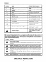
SYMBOLS
SYMBOL
NAME
DESIGNATION/EXPLANATION
V
Volts
Voltage
A
Amperes
Current
Hz
Hertz
Frequency (cycles per second)
min
Minutes
Time
•"k.,
Alternating Current
Type or a characteristic of current
Direct Current
Type or a characteristic of current
No Load Speed
Rotational speed, at no load
Class II Construction
Designates Double Insulated
Construction Tools
=_
no
.../min
Revolutions or Reciprocation
Per Minute
Revolutions, strokes, surface
speed, orbits etc. per minute
Indicates danger, warning or caution.
,_
Safety Alert Symbol
It means attention.J Your safety is
involved.
The purpose of safety symbols is to attract your attention to possible dangers. The safety symbols, and
the explanations with them, deserve your careful attention and understanding. The safety warnings do
not by themselves eliminate any danger. The instructions or warnings they give are not substitutes for
proper accident prevention measures.
SYMBOL
MEANING
A
SAFETY ALERT SYMBOL:
A
A
A
DANGER: Failure to obey a safety warning will result in serious injury to yourself or to others.
Always follow the safety precautions to reduce the risk of fire, electric shock, and personal injury.
NOTE:
Advises you of information or instructions vital to the operation or maintenance of the equipment.
Indicates danger, warning, or caution. May be used in conjunction
pictographs.
with other symbols or
WARNING: Failure to obey a safety warning can result in serious injury to yourself or to others.
Always follow the safety precautions to reduce the risk of fire, electric shock, and personal injury.
CAUTION: Failure to obey a safety warning may result in property damage or personal injury to
yourself or to others. Always follow the safety precautions to reduce the risk of fire, electric shock,
and personal injury.
SAVE THESE INSTRUCTIONS
6
Your circular saw has been shipped completely
assembled except for the blade. Inspect it carefully to
make sure no breakage or damage has occurred
during shipping. If any parts are damaged or missing,
contact your nearest Sears Retail Store to obtain
replacement parts before attempting to operate saw. A
blade, blade wrench, and this owner's manual are also
included.
,_i
Horsepower
Model 315.108400
Model 315.108410
Cutting Depth at 0 ° Bevel Cut
2-1/3
2-1/2
Input
11 Amperes
12 Amperes
Blade Diameter
7-1/4 in. (184 mm)
Blade Arbor
YOUR CIRCULAR
Cutting Depth at 51.5 ° Bevel Cut
1-13/16 in. (46 mm)
1-5/8 in. (41 mm)
120 volts, 60 Hz, AC
No Load Speed
Model 315.108400
Model 315.108410
4,700 RPM
5,000 RPM
5/8 in. (16 mm)
SAW
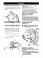
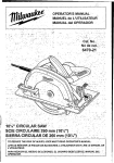
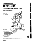
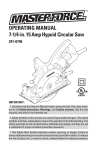
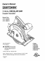
See Figure 1.
Before attempting to use any tool, familiarize yourself
with all operating features and safety requirements.
Your circular saw has many features for making
cutting operations more pleasant and enjoyable.
Safety, performance and dependability have been
given top priority in the design of this saw making it
easy to maintain and operate.
Features include easily operated bevel cut and depth
of cut adjustment mechanisms, positive 0 ° bevel stop,
length of cut scale, depth of cut scale, directed air flow
for keeping line of cut clear, blade wrench storage,
dust chute, and spindle lock button on Model
315.108410 only.
CAUTION:
Carefully read through this entire
owner's manual before using your new circular
saw. Pay close attention to the Rules For Safe
Operation, Warnings and Cautions. If you use
your circular saw properly and only for what it is
intended, you will enjoy years of safe, reliable
service.
APPLICATIONS
(Use only for the purpose listed below)
•
2-3/8 in. (60 mm)
Cutting Depth at 45 ° Bevel Cut
Rating
Model 315.108400
Model 315.108410
KNOW
WARNING:
If any parts are missing, do not
operate this tool until the missing parts are
replaced. Failure to do so could result in possible
serious personal injury.
Cutting all types of wood products (lumber,
plywood, paneling).
ELECTRICAL
CONNECTION
Your circular saw has a precision built electric motor. It
should be connected to a power supply that is 120
volts, 60 Hz, AC only (normal household current). Do
not operate this tool on direct current (DC). A substantial
voltage drop will cause a loss of power and the motor
will overheat. If your saw does not operate when
plugged into an outlet, double-check the power supply.
SWITCH
To turn your saw ON, depress the switch trigger.
Release switch trigger to turn your saw OFF.
DUST CHUTE
To direct saw dust and chips away from the operator,
a dust chute is located on the side of the upper blade
guard. An optional dust nozzle, that fits over the dust
chute, is available at your nearest Sears Retail Store.
SPINDLE
LOCK BU'I-rON
- MODEL
315.108410
A spindle lock button has been provided for locking the
spindle on your saw in a stationary position.
_k
WARNING:
Do not allow familiarity with your
saw to make you careless. Remember that a
careless fraction of a second is sufficient to inflict
severe injury.
MODEL 315.108400
/ MODEL 315.108410
SWITCH
TRIGGER
LOWERBLADE
GUARDHANDLE
DUSTCHUTE
UPPER
_ARD
SEVELCUT
ADJUSTMENT
NU_
BASE
ASSEMBLY
SPINDLELOCKBUTTON
(MODEL315.108410ONLY)
LOWER
BLADEGUARD
(
BLADE
DEPTHOF
CUTSCALE
DEPTHOF
CUTADJUSTMENT
(WINGNUT)
BLADEWRENCH
STORAGEAREA
BLADEWRENCH
8
Fig. 1
WARNING:Your
saw should never be
connected to power supply when you are
assembling parts, making adjustments,
assembling or removing blades, cleaning, or
when not in use. Disconnecting your saw will
prevent accidental starting that could cause
serious personal injury.
_1
,_
•
OUTERBLADEWASHER("D" WASHER)
CUPPEDSIDEOF
SPRINGWASHER
BLADE
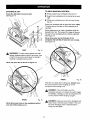
See Figures 2, 3, and 4,
_
•
Unplug your saw.
WARNING:
Failure to unplug your saw could
result in accidental starting causing possible
serious personal injury.
•
Fig. 3
Replace "D" washer and spring washer.
Note: "Cupped" side of spring washer goes against
"D" washer. See Figure 3.
Replace blade screw. Tighten blade screw securely.
Note: Turn blade screw clockwise to tighten.
Return blade wrench to storage area.
Note: Always place angled portion of blade wrench
up as shown in Figure 1.
REMEMBER: Never use a blade that is too thick to
allow the "D" washer to engage with the flat on the
spindle.
Remove blade wrench from storage area.
See Figure I.
• Place yoursaw on a pieceofwood as shown in
Figure4, and remove bladescrew.See Figure2.
Note: Turnbladescrew counterclockwise
toremove.
TO REMOVE BLADE:
• Remove springwasher, and outerbladewasher
("D"washer).See Figure2
SPINDLE
OUTSI
SPRINGWASHER
•
TO ASSEMBLE BLADE:
•
Fit saw blade inside lower blade guard and onto
spindle. Note: The saw teeth point upward at the
front of saw as shown in Figure 2.
WARNING: A 7-1/4 in. blade is the maximum
blade capacity of your saw. Never use a blade that
is too thick to allow outer blade washer to engage
with the flat on the spindle. Larger blades will come
in contact with the blade guards, while thicker
blades will prevent blade screw from securing
blade on spindle. Either of these situations could
result in a serious accident.
TO ASSEMBLE
OR REMOVE
MODEL 315.108400
•
WARNING:
If inner blade washer has been
removed, replace it before placing blade on
spindle. Failure to do so could cause an accident
since blade will not tighten properly.
LOWERBLADE
GUARDHANDLE
•
Remove blade wrench from storage area.
See Figure I.
•
Place your saw on a piece of scrap wood as shown
in Figure 4, and remove blade screw. See Figure 2.
Note: With blade teeth embedded in the wood, turn
blade screw counterclockwise to remove.
•
BLADE
Remove spring washer and outer blade washer
("D" washer). See Figure2
Note: Blade can be removed at this point.
LOWERBLADE
GUARDHANDLE
TO
LOOSEN
SPRING
WASHER
INNERBLADE
WASHER
OUTERBLADE
WASHER
(" D"WASHER)
•
BLADE
SCREW
BLADE
WRENCH
TO
TIGHTEN
Fig. 2
Wipe a drop of oil onto inner blade washer and
outer blade washer ("D" washer) where they
contact blade.
BLADESCREW
9
Fig. 4
TO ASSEMBLE
OR REMOVE
MODEL 315.10841 O0
BLADE
•
See Figures 5, 6, and 7.
•
Replace "D" washer and spring washer.
Note: "Cupped" side of spring washer goes
against "D" washer. See Figure 6.
Unplug your saw.
,_
OUTERBLADEWASHER("D" WASHER)
WARNING:
Failure to unplug your saw could
result in accidental starting causing possible
serious personal injury.
SPINDLE
LOCK BUTTON
- MODEL
315.108410
If your saw is model 315.108410 it has a spindle lock
button for locking the spindle on your saw in a stationary
position. Depress and hold the spindle lock button while
installing, changing or removing the blade.
TO ASSEMBLE BLADE:
CUPPEDSIDE OF
SPRINGWASHER
•
OUTSIDEOF
SPRINGWASHER
Fig. 6
Depress spindle lock button, then replace blade
screw. Tighten blade screw securely.
Note: Turn blade screw clockwise to tighten.
Return blade wrench to storage area.
Note: Always place angled portion of blade
wrench up as shown in Figure 1.
•
Remove blade wrench from storage area.
See Figure 1.
•
Position your saw as shown in Figure 7, depress
spindle lock button, and remove blade screw. See
Figure 5.
•
Note: Turn blade screw counterclockwise to remove.
REMEMBER: Never use a blade that is too thick to
allow the "D" washer to engage with the flat on
the spindle.
•
Remove spring washer, and outer blade washer
("D" washer). See Figure 5.
TO REMOVE BLADE:
SPINDLE
LOWERBLADE
GUARDHANDLE
•
Remove blade wrench from storage area.
See Figure 1.
•
Position your saw as shown in Figure 7, depress
spindle lock button, and remove blade screw.
Note: Turn blade screw counterclockwise to remove.
BLADE
•
Remove spring washer and outer blade washer
("D" washer). See Figure 5.
Note: Blade can be removed at this point.
DEPRESSTO
LOCK
SPRING
WASHER
INNERFLANGE
BUSHING
OUTER
WASHER
("D" WASHER)
•
,_
•
SPINDLELOCK
BUTTON
BLADE
SCREW
Fig. 5
Wipe a drop of oil onto inner flange bushing and
outer blade washer ("D" washer) where they
contact blade.
TO
TIGHTEN
WARNING:
If inner flange bushing has been
removed, replace it before placing blade on
spindle. Failure to do so could cause an accident
since blade will not tighten properly.
BLADE
SCREW
BLADE
WRENCH
Fit saw blade inside lower blade guard and onto
spindle. Note: The saw teeth point upward at the
front of saw as shown in Figure 5.
TO
LOOSEN
10
Pig. 7
SAW BLADES
KICKBACK
The best of saw blades will not cut efficiently if they
are not kept clean, sharp, and properly set. Using a
dull blade will place a heavy load on your saw and
increase the danger of kickback. Keep extra blades
on hand, so that sharp blades are always available.
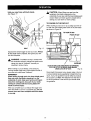
See Figure 9.
Gum and wood pitch hardened on blades will slow
your saw down. Use gum and pitch remover, hot
water, or kerosene to remove these accumulations.
Do not use gasoline.
BLADE
GUARD
SYSTEM
KICKBACKi<l_
The lower blade guard attached to your circular
saw is there for your protection and safety. It
should never be altered for any reason. If it
becomes damaged or begins to return slow or
sluggish, do not operate your saw until the
damage has been repaired or replaced. Always
leave guard in operating position when using saw.
BLADESETTOO DEEP
The best guard against kickback is to avoid
dangerous practices.
Kickback occurs when the blade stalls rapidly and the
saw is driven back towards you. Blade stalling is
caused by any action which pinches the blade in the
wood.
_1= DANGER: When sawing through workpiece,
lower blade guard does not cover blade on the
underside of workpiece. Since blade is exposed
on underside of workpiece, keep hands and
fingers away from cutting area. Any part of your
body coming in contact with moving blade will
result in serious injury. See Figure 8.
_
,_
DANGER: Release switch immediately if blade
binds or saw stalls. Kickback could cause you to
lose control of your saw. Loss of control can lead
to serious injury.
KICKBACK
LOWERBLADEGUARD
IS IN UP POSITION
BLADEEXPOSEDON
UNDERSIDEOF WORKPIECE
Fig. 9
IS CAUSED
BY:
•
Incorrect blade depth setting. See Figure 9.
•
Sawing into knots or nails in workpiece.
•
Twisting blade while making a cut.
•
Making a cut with a dull, gummed up, or improperly
set blade.
•
Incorrectly supporting workpiece. See Figure 10.
Fig. 8
CAUTION: Never use saw when guard is not
operating correctly. Guard should be checked for
correct operation before each use. If you drop
your saw, check the lower blade guard and
bumper for damage at all depth settings before
reuse. Note: The guard is operating correctly
when it moves freely and readily returns to the
closed position, tf for any reason your lower
blade guard does not close freely, take it to the
nearest Sears Repair Center for service before
using.
Fig. 10
11
•
Forcing a cut.
•
Cutting warped or wet lumber.
•
Tool misuse or incorrect operating procedures.
TO LESSEN
•
Always
correct
exceed
Figure
THE CHANCE
OF KICKBACK:
keep the correct blade depth setting - the
blade depth setting for all cuts should not
1/4 inch below the material to be cut. See
11.
•
When making a cut use steady, even pressure.
Never force cuts.
•
Do not cut warped or wet lumber.
•
Always hold your saw firmly with both hands and
keep your body in a balanced position so as to
resist the forces of kickback should it occur.
When using your saw, always stay alert and
exercise control. Do not remove your saw from
workpiece while the blade is moving.
DEPTH
OF CUT ADJUSTMENT
See Figure 13.
Always keep correct blade depth setting. The correct
blade depth setting for all cuts should not exceed 1/4
inch below the material to be cut. More blade depth
will increase the chance of kickback and cause the cut
to be rough. For more depth of cut accuracy, a scale
is located on the upper blade guard.
TO ADJUST
•
CORRECTBLADEDEPTHSETFING= BLADEEXPOSED
1/4 in. OR LESSON UNDERSIDEOF WORKPIECE
Fig. 11
•
Inspect the workpiece for knots or nails before.
beginning a cut. Never saw into a knot or nail.
•
Make straight cuts. Always use a straight edge
guide when rip cutting. This helps prevent twisting
the blade in the cut.
•
Always use clean, sharp and properly set blades,
Never make cuts with dull blades.
•
To avoid pinching the blade, support the workpiece
properly before beginning a cut. The right and
wrong ways to support large pieces of work are
shown in Figures 10 and 12.
,_
BLADE
DEPTH
Unplug your saw.
WARNING:
Failure to unplug your saw could
result in accidental starting causing possible
serious personal injury.
DEPTHOF
CUTSCALE
BRACKET
WING
NUT
TO
TIGHTEN
TO RAISE
ASSEMBLY
W
RIGHT
•
Loosen wing nut. See Figure 13.
•
Determine the desired depth of cut.
•
Locate depth of cut scale on back of upper blade
guard.
•
Hold base flat against the workpiece and raise or
lower saw until the indicator mark on bracket aligns
with notch on blade guard.
•
Tighten wing nut securely.
Fig. 12
12
TO LOWER
Fig. 13
STARTING
TO HELP MAINTAIN
A CUT
Know the right way to use your saw.
See Figure 14.
CONTROL:
•
Always support your workpiece near the cut.
•
Support your workpiece so the cut will be on your
right.
•
Clamp your workpiece so it will not move during
the cut.
Place your workpiece with its good side down. Note:
The good side is the side On which appearance is
important.
Before beginning a cut, draw a guideline along the
desired line of cut. Then place front edge of base on
that part of your workpiece that is solidly supported.
See Figure 14.
Never place your saw on that part of the
workpiece that will fall off when the cut is made.
See Figure 16.
RIGHT
,_
Fig. 14
WARNING:
To make sawing easier and safer,
always maintain proper control of your saw. Loss
of control of your saw could cause an accident
resulting in possible serious injury.
Never use your saw as shown in Figure 15.
WRONG
Fig. 16
Keep the cord away from cutting area. Always place
the cord to prevent it from hanging up on the
werkpiece while making a cut.
WRONG
_1
DANGER: If the cord hangs up on the
workpiece during a cut, release the switch trigger
immediately. Unplug your saw and reposition the
cord to prevent it from hanging up again.
,_i
DANGER: Using your saw with a damaged cord
could result in serious injury or death. If the cord
has been damaged, have it replaced before
using your saw again.
Fig. 15
Never place your hand on the workpiece behind
your saw while making a cut.
13
Hold your saw firmly with both hands.
See Figure 17.
,_
CAUTION:
When lifting your saw from the
workpiece, the blade is exposed on the
underside of your saw until the lower blade guard
closes. Make sure lower guard is closed before
setting your saw down on work surface.
TO CROSS
CUT OR RIP CUT
When making a cross cut or rip cut, align your line of
cut with the outer blade guide notch on the saw base
as shown in Figure 18.
TOPVIEW OFSAW
FRONTOF SAW
BLADE
GUIDENOTCH
RIGHT
Fig. 17
Squeeze the switch trigger to start your saw. Always
let the blade reach full speed, then guide your saw
into the workpiece.
,_i
WARNING:
The blade coming in contact with
the workpiece before it reaches full speed could
cause your saw to "kickback" towards you
resulting in serious injury.
_m
GUIDELINE
ALIGNOUTERBLADEGUIDENOTCHON SAW BASE
WITH LINEOF CUTAS SHOWNWHENMAKING
CROSSCUTSOR RIP CUTS
Fig. 18
When making a cut use steady, even pressure.
Forcing causes rough cuts, could shorten the life of
your saw and could cause "kickback."
Since blade thicknesses vary, always make a trial cut
in scrap material along a guideline to determine how
much, if any, the guideline must be offset to produce
an accurate cut. Note: The distance from the line of
cut to the guideline is the amount you should offset
the guideline.
REMEMBER:
When sawing through work, the lower blade guard
does not cover the blade, exposing it on the
underside of work. Keep your hands and fingers
away from cutting area. Any part of your body
coming in contact with the moving blade will
result in serious injury.
After you complete your cut release the trigger and
allow the blade to come to a complete stop. Do not
remove your saw from werkpiece while the blade
is moving.
14
TO BEVEL
CUT
The angle of cut of your saw may be adjusted to any
desired setting between zero and 51.5 °. Note: When
making cuts at 51.5 ° blade should be set at full depth
of cut, with edge guide screw removed.
When making a bevel cut hold your saw firmly with
both hands as shown in Figure 20.
Rest the front edge of the base on the workpiece.
Squeeze the switch trigger to start your saw. Always
let the blade reach full speed, then guide your saw
into the workpiece.
When making 45 ° bevel cuts, there is a notch in the
saw base to help you line up the blade with the line of
cut. See Figure 19.
BEVEL
SCALE
LOWER
BLADEGUARD
,_
GUIDELINE
BLADE
GUIDENOTCH
Fig. 20
WARNING: The blade coming in contact with
the workpiece before it reaches full speed could
cause saw to "kickback" toward you resulting in
serious injury.
After you complete your cut release the trigger and
allow the blade to come to a complete stop. After the
blade has stopped, lift your saw from the workpiece.
BEVELADJUSTMENT
WINGNUT
ALIGN INNERBLADEGUIDENOTCHON SAWBASEWITH
LINE OF CUTAS SHOWNWHENMAKING45° BEVELCUTS
TO ADJUST
•
Fig. 19
BEVEL SETTING
Unplug your saw.
Align your line of cut with the inner blade guide notch
on the saw base when making 45 ° bevel cuts.
_
Since blade thicknesses vary and different angles
require different settings, always make a trial cut
in scrap material along a guideline to determine
how much you should offset the guideline on the
board to be cut,
•
Loosen wing nut. See Figure 19.
•
Raise motor housing end of saw until you reach
desired angle setting on bevel scale.
See Figure 19.
•
Tighten wing nut securely.
_k
15
WARNING:
Failure to unplug your saw could
result in accidental starting causing possible
serious personal injury.
WARNING:
Attempting bevel cut without wing
nut securely tightened can result in serious
injury.
POSITIVE
TO ADJUST
0 ° BEVEL STOP
See Figure 21.
BEVEL
ADJUSTMENT
•
ADJUSTMENT
SCREW
,_
WARNING:
Failure to unplug your saw could
result in accidental starting causing possible
serious personal injury.
•
Loosen wing nut.
•
Loosen hex nut securing adjustment screw.
•
Turn screw and adjust base until square with saw
blade.
•
Tighten hex nut and wing nut securely.
_IL
NUT
Unplugyoursaw.
WARNING:
Attempting to make cuts without
wing nut securely tightened can result in serious
injury,
POSITIVE0° BEVELSTOP
CARPENTER'S
SQUARE
LENGTH
SAW BLADE
OF CUT SCALE
See Figure 22.
Fig. 21
Your saw has a positive 0 ° bevel stop, that has been
factory adjusted to assure 0° angle of your saw blade
when making 90 ° cuts. However, misalignment can
occur during shipping.
LENGTHOFCUT SCALE
A length of cut scale has been provided on the base
of your saw. It is parallel with the saw blade and can
be used to measure the distance into material the
blade has cut. Note: Six inches is the maximum
length of cut that can be measured. Also, it is
accurate only when the depth of cut is set at full
maximum depth.
TO CHECK
•
_,
Unplug your saw.
WARNING:
Failure to unplug your saw could
result in accidental starting causing possible
serious personal injury.
•
Place your saw in an upside down position on
workbench. See Figure 21.
•
Using a carpenter's square, check squareness of
saw blade to the base of your saw.
Fig. 22
16
TO POCKET
CUT
C-clamps, firmly clamp a straight edge to the
workpiece and guide the saw along the straight edge
to achieve a straight rip cut. Do not bind the blade in
the cut. If using the optional rip guide, see the
following instructions and Figure 25.
See Figure 23.
,_
WARNING: Always adjust bevel setting to zero
before making a pocket cut. Attempting a pocket
cut at any other setting can result in loss of control
of your saw possibly causing serious injury.
ALTERNATEMETHODFORRIP CUTTING
STRAIGHT
EDGE
Adjust the bevel setting to zero, set blade to correct
blade depth setting, and swing the lower blade guard
up using the lower blade guard handle.
Always raise the lower blade guard with the
handle to avoid serious injury.
While holding lower blade guard by the handle, firmly
rest the front of the base flat against the workpiece
with the rear of the handle raised so the blade does
not touch the workpiece.
See Figure 23.
LOWER
BLADEGUARD
WORKPIECE
C-CLAMPS
Fig. 24
TO ASSEMBLE
•
_i
POCKET
CUT
•
LOWERBLADE
GUARDHANDLE
OPTIONAL
RIP GUIDE
Unplug your saw.
WARNING:
Failure to unplug your saw could
result in accidental starting causing possible
serious personal injury.
Place rip guide through holes in saw base as
shown in Figure 25.
Fig. 23
RIP
Squeeze the switch trigger to start your saw. Always
let the blade reach full speed then slowly lower
blade into the workpiece until base is flat against
workpiece.
After you complete your cut release the trigger and
allow the blade to come to a complete stop. After the
blade has stopped, remove it from the workpiece.
Corners may then be cleared out with a hand saw or
sabre saw.
_1
RIPGUIDE
(EDGEGUIDE)
PLACERIP
GUIDETHRU HOLES
WARNING:
Never tie the lower blade guard in a
raised position. Leaving the blade exposed could
lead to serious injury.
Fig. 25
•
Adjust rip guide to the width needed.
TO RIP CUT
•
Tighten rip guide screw securely.
OPTIONAL RIP GUIDE (EDGE GUIDE)
See Figure 24.
When using a rip guide, position the face of the rip
guide firmly against the edge of workpiece. This
makes for a true cut without pinching the blade. The
guiding edge of workpiece must be straight for your
cut to be straight. Use caution to prevent the blade
from binding in the cut.
Use a guide when making long or wide rip cuts with
your saw. An optional rip guide with a five inch scale is
available at your Sears Retail Store or you can make
an efficient rip guide by clamping a straight edge to
your workpiece. Secure the workpiece. Using
17
OPTIONAL
DUST
NOZZLE
KIT
UPPER
BLADEGUARD
_ee Figure 26.
An optional dust nozzle kit, part no. 982829-001, is
available for purchase at your nearest Sears Retail
Store. As shown in Figure 26, the adapter fits over the
dust chute which is located on the upper blade
guard.The nozzle attaches to the adapter.
Note: If you use the nozzle, you should always
connect it to a standard vacuum hose.
TO ATTACH
•
_k
DUST NOZZLE
KIT
Unplug your saw.
WARNING:
Failure to unplug your saw could
result in accidental starting causing possible
serious personal injury.
•
Orient adapter to fit into the dust chute opening (1)
on upper blade guard. Secure adapter with screw
(2) provided.
•
When using a vacuum hose, align hole in nozzle
with raised lip on adapter and snap into place (3).
CHUTE
HOLE
ADAPTER
SCREW
NOZZLE
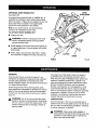
GENERAL
Fig. 26
It has been found that electric tools are subject to
accelerated wear and possible premature failure
when they are used on fiberglass boats, sports cars,
wallboard, spackling compounds, or plaster. The
chips and grindings from these materials are highly
abrasive to electric tool parts, such as bearings,
brushes, commutators, etc. Consequently, it is not
recommended that this tool be used for extended
work on any fiberglass material, wallboard, spackling
compounds, or plaster. During any use on these
materials, it is extremely important that the tool is
cleaned frequently by blowing with an air jet.
Only the parts shown on parts list, page 21, are
intended to be repaired or replaced by the customer.
All other parts represent an important part of the
double insulation system and should be serviced only
at a Sears Service Center.
Avoid using solvents when cleaning plastic parts.
Most plastics are susceptible to damage from various
types of commercial solvents and may be damaged
by their use. Use clean cloths to remove dirt, carbon
dust, etc.
,_L
RAISED
LUBRICATION
WARNING:
Do not at any time let brake fluids,
gasoline, petroleum-based products, penetrating
oils, etc. come in contact with plastic parts. They
contain chemicals that can damage, weaken or
destroy plastic.
All of the bearings in this tool are lubricated with a
sufficient amount of high-grade lubricant for the life of
the unit under normal operating conditions. Therefore,
no further lubrication is required.
,_k
18
WARNING: Always wear safety goggles or
safety glasses with side shields during power tool
operation or when blowing dust. If operation is
dusty, also wear a dust mask.
DOUBLE
INSULATION
A wire gage size (A.W.G.) of at least 16 is
recommended for an extension cord 100 feet or less
in length. When working outdoors, use an extension
cord that is suitable for outdoor use. The cord's jacket
will be marked WA.
Double insulation is a concept in safety in electric
power tools, which eliminates the need for the usual
three-wire grounded power cord. Al! exposed metal
parts are isolated from the internal metal motor
components with protecting insulation. Double
insulated tools do not need to be grounded.
,_k
CAUTION: Keep extension cords away from the
cutting area and position the cord so that it will
not get caught on lumber, tools, etc., during
cutting operation.
_k
WARNING:
Check extension cords before each
use. If damaged replace immediately. Never use
tool with a damaged cord since touching the
damaged area could cause electrical shock
resulting in serious injury.
IMPORTANT
Servicing of a tool with double insulation requires
extreme care and knowledge of the system and should
be performed only by a qualified service technician. For
service, we suggest you return the tool to your nearest
Sears Service Center for repair. Always use original
factory replacement parts when servicing.
EXTENSION
CORDS
The use of any extension cord will cause some loss of
power. To keep the loss to a minimum and to prevent
tool overheating, use an extension cord that is heavy
enough to carry the current the tool will draw.
The following recommended
Extension cords suitable for use with your saw are
available at your nearest Sears Retail Store.
accessories are currently available at Sears Retail Stores.
•
7-1/4 in.
40 Tooth General Purpose Cut-Off Blade
•
7-1/4 in.
35 Tooth Master Combination
•
7-1/4 in.
200 Tooth Plywood Blade
•
7-1/4 in.
18 Tooth Carbide Blade
•
7-1/4 in.
18 Tooth Mach II Silver Series Carbide Blade
•
7-1/4 in.
24 Tooth Mach II Silver Series Carbide Blade
•
7-1/4 in.
24 Tooth Combination Carbide Blade
Blade
•
Rip Guide
•
Dust Nozzle Kit - Part No. 982829-001
_L
WARNING:
The use of attachments or accessories
not listed might be hazardous.
WARRANTY
FULL ONE YEAR WARRANTY ON CRAFTSMAN
CIRCULAR
SAW
If this I"RI_ICl'$MAN Circular Saw fails to give complete satisfaction within one year from the date of purchase,
RETURN IT TO THE NEAREST SEARS STORE OR SEARS SERVICE CENTER IN THE UNITED STATES,
and Sears will replace it, free of charge.
If this r'RItFTINaH
Circular Saw is used for commercial
days from the date of purchase.
or rental purposes, this warranty applies for only 90
This warranty gives you specific legal rights, and you may also have other rights which vary from state to state.
Sears, Roebuck and Co., Dept. 817WA, Hoffman Estates, IL 60179
19
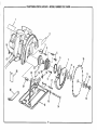
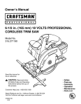
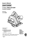
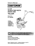
CRAFTSMAN
CIRCULAR
SAW - MODEL NUMBER
315.108400
2
18
4
6
8
21
26
23
10
7
18
9
11
5
12
17
24
25
13
16
15
,
14
20
,
CRAFTSMAN
CIRCULAR
SAW-
MODEL
NUMBER
315.108400
I
The model number will be found on a plate attached to the motor housing. Always mention the model number in all correspondence regarding your
CIRCULAR SAW or when ordering repair parts.
SEE BACK
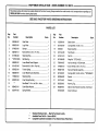
Key
No.
PAGE
FOR
PARTS
ORDERING
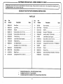
PARTS
LIST
Part
Number
Description
Key
No.
Quan.
I
INSTRUCTIONS
Part
Number
Description
Quan.
1
982595-001
Data Plate .......................................................
1
15
3053002
Base Assembly ...............................................
1
2
982820-001
Logo Plate ......................................................
1
16
931744-059
Flat Washer ....................................................
2
3
974900-001
Bumper ...........................................................
1
17
941401-310
Roll Pin ...........................................................
1
4
982492-131
* Screw (#8-32 x 3/4 in. Fil. Hd.) ....................... 1
18
621438-006
Wing Nut **STD541625 .................................. 2
5
610122-003
* Screw (#8-32 x 3/8 in. Pan Hd.) ..................... 3
19
706404-007
Hex Nut (#8-32) **STD541008 ....................... 1
6
967952-001
Torsion Spring ................................................
1
2O
6447801
Lower Blade Guard Support ........................... 1
7
982380-001
Lower Blade Guard Assembly ........................ 1
21
614658-010
* Screw (#8-32 x 5/8 in. Pan Hd.) ..................... 1
8
718602-804
Retaining Ring ................................................
1
22
982481-001
Gear and Spindle Assembly ........................... 1
9
999982-001
Inner Blade Washer ........................................
1
23
621433-001
Carriage Bolt (1/4-20 x 5/8 in.) **STD532507 1
Saw Blade 7-1/4 in. for 5/8 in. Arbor ............... 1
24
5542301
10
Spacer ............................................................
1
11
998463-001
Outer Blade Washer .......................................
1
25
974716-001
Wrench ...........................................................
1
12
623547-002
Spring Washer ................................................
1
26
982832-001
Warning Tag ...................................................
1
13
612999-001
Blade Screw ...................................................
1
27
982829-001
Optional Dust Nozzle Assembly - Not Shown
14
621433-018
972000-823
Owner's Manual
Carriage Bolt (1/4-20 x 3-3/4 in.) .................... 1
*
**
***
Standard Hardware Item -- May Be Purchased Locally
Available From Div. 98 -- Source 980.00
Complete Assortment Available At Your Nearest Sears Retail Store
21
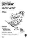
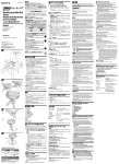
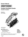
CRAFTSMAN
CIRCULAR
SAW - MODEL NUMBER
315.108410
2
7
8
6
9
23
22
13
10
11
12
21
26
27
16
19
18
17
22
CRAFTSMAN
CIRCULAR
SAW-
MODEL
NUMBER
315.108410
I
The model number will be found on a plate attached to the motor housing. Always mention the model number in all correspondence regarding your
CIRCULAR SAW or when ordering repair parts,
SEE
Key
No.
Pad
Number
Description
BACK
PAGE
FOR
PARTS
ORDERING
PARTS
LIST
Key
No.
Quan.
I
INSTRUCTIONS
Pad
Number
Description
Quan.
1
982596-001
Data Plate .......................................................
1
16
612999-001
Blade Screw ...................................................
2
982820-001
Logo Plate ......................................................
1
17
621433-007
Carriage Bolt (1/4-20 x 4 in.) .......................... 1
3
974900-001
Bumper ...........................................................
1
18
3053002
Base Assembly ...............................................
1
4
982492-131
* Screw (#8-32 x 3/4 in. Fil. Hd.) ....................... 1
19
931744-059
Flat Washer ....................................................
2
5
617096-002
Retaining Ring ................................................
1
20
941401-310
Roll Pin ...........................................................
1
6
**STD315535
Ball Bearing ....................................................
!
21
621438-006
Wing Nut **STD541625 ..................................
2
7
982828-001
Lower Blade Guard Support ........................... 1
22
706404-007
Hex Nut (#8-32) **STD541008 ....................... 1
8
610122-003
* Screw (#8-32 x 3/8 in. Pan Hd.) ..................... 3
23
614658-010
* Screw (#8-32 x 5/8 in. Pan Hd.) ..................... 1
9
967952-001
Torsion Spring ................................................
1
24
982821-001
Gear and Spindle Assembly ........................... 1
10
982380-001
Lower Blade Guard Assembly ........................ 1
25
621433-001
Carriage Bolt (1/4-20 x 5/8 in.) **STD532507
1
11
718602-804
Retaining Ring ................................................
1
26
982366-002
Spacer ............................................................
1
12
967887-003
Inner Flange Bushing .....................................
13
1
1
27
974716-001
Wrench ...........................................................
1
Saw Blade 7-1/4 in. for 5/8 in. Arbor ............... 1
28
982832-001
Warning Tag ...................................................
1
29
982829-001
Optional Dust Nozzle Assembly-
972000-823
Owner's Manual
14
998463-001
Outer Blade Washer .......................................
1
15
623547-002
Spring Washer ................................................
1
*
**
***
Not Shown
Standard Hardware Item -- May Be Purchased Locally
Available From Div.98 -- Source 980,00
Complete Assortment Available At Your Nearest Sears Retail Store
i
23
Get it fixed, at your home or ours!
For repair of major brand appliances in your own home...
no matter who made it, no matter who sold it!
1-800-4-MY-HOME
sMAnyt,me,
day or n,ght
(1-800-469-4663)
www.sears.com
To bring in products such as vacuums, lawn equipment and electronics
for repair, call for the location of your nearest Sears Parts & Repair Center.
1-800-488-1222
Anytime,
day or night
www.sears.com
For the replacement parts, accessories and owner's manuals
that you need to do-it-yourself, call Sears PartsDirect SM!
1-800-366-PART
(1-800-366-7278)
6 a.m. - 11 p m CST,
7 days a week
www.sears.com/partsdirect
To purchase or inquire about a Sears Service Agreement:
1-800-827-6655
7 a.m. - 5 p.m
Para pedir servtclo de reparaci6n a domictlio,
y para ordenar plezas con entrega a domlclho
1-888-SU-HOGAR
s.
CST, Mon. - Sat.
Au Canada
pour servtce en fran(;a_s'
1-877-LE-FOYER s_
(1-877-533-6937)
(1-888-784-6427)
® Registered Trademark / rM Trademark of Sears
© Sears
Roebuck
and Co
® Marca Reglstrada
/ T_ Marca de Fabnca de Sears
Roebuck and Co
Roebuck and Co