1
Instructions for commissioning, maintenance
and troubleshooting
For the competent person
Instructions for commissioning, maintenance and troubleshooting
Solar heating system
with auroSTOR
Solar hot water system
GB, IE
Table of contents
Table of contents
1
1.1
1.2
1.3
1.4
1.5
1.6
1.7
Notes on the documentation ................................ 3
Other applicable documents ................................... 3
Storing documents ..................................................... 3
Symbols used ............................................................... 3
Applicability of the instructions .............................. 3
Cylinder identification plate .....................................4
CE label .........................................................................4
Benchmark ...................................................................4
2
2.1
2.1.1
2.1.2
2.2
2.3
2.4
2.4.1
2.4.2
2.5
2.5.1
2.5.2
2.5.3
Safety instructions and regulations ..................4
Safety and warning information .............................4
Classification of action-related warnings .............4
Structure of warnings ................................................4
Intended use ................................................................5
General safety instructions ......................................5
Overview of EU standards ........................................6
General information on solar heating system .....6
Cylinder and cylinder assembly .............................. 7
Regulations for Great Britain................................... 7
Technical Guidance ..................................................... 7
Related documents..................................................... 7
Regulations for the prevention of accidents .......8
3
3.1
3.2
3.3
3.4
System description ..................................................8
Design and function of solar heating system ......8
Electrical wiring......................................................... 10
Hot water temperature regulation ....................... 10
Heating control.......................................................... 10
4
4.1
4.1.1
4.1.2
4.2
4.2.1
4.2.2
4.2.3
4.2.4
4.3
4.3.1
4.3.2
4.3.3
4.3.4
Description of the components ............................11
auroSTOR solar cylinder ...........................................11
Safety devices.............................................................12
Cylinder operating elements...................................12
Solar fluid ....................................................................14
Properties of solar fluid ...........................................14
Solar circuit frost and corrosion protection
system ..........................................................................14
Cylinder frost protection..........................................14
Safety data sheet for Vaillant solar fluid .............15
System configuration ................................................17
Vaillant controllers and their basic functions.....17
Control functions .......................................................18
Technical data of the auroSTOR solar cylinder 20
Dimensions .................................................................22
5
5.1
5.2
5.3
Assembly ...................................................................23
Scope of delivery ......................................................23
Transporting the cylinder .......................................23
Requirements for installation site ........................23
2
6
6.1
6.2
6.2.1
6.2.2
6.2.3
6.2.4
6.3
6.4
6.5
6.5.1
6.5.2
6.5.3
6.6
6.6.1
6.6.2
6.6.3
6.6.4
6.6.5
6.7
6.7.1
6.7.2
6.8
6.8.1
6.8.2
6.8.3
6.8.4
6.8.5
6.8.6
7
7.1
7.2
7.3
7.4
7.5
7.6
7.7
7.8
7.9
7.10
7.11
7.12
Installation ................................................................24
Installation sequence ...............................................24
Installation of solar circuit piping .........................24
Piping material in the solar circuit .......................24
Layout of piping in the solar circuit .....................24
Realisation of solar circuit piping .........................25
Venting the solar circuit..........................................27
Pipes for the primary heating circuit ..................29
Installing hot water pipes .......................................29
Hot water thermostat mixer ..................................29
Installing the hot water thermostat mixer
(without secondary circulation line) ................... 30
Installing the hot water thermostat mixer
(with secondary circulation line) .......................... 30
Setting the hot water thermostat mixer ............ 30
Installation of cold mains inlet ...............................31
Pressure in cold mains inlet ....................................31
Mounting the safety assembly ...............................31
Mounting the expansion vessel .............................32
Mounting the drain valve ........................................32
Laying the pipes to the tundish ............................32
Installation of discharge pipe ................................32
Design of discharge pipe.........................................32
High drain ...................................................................34
Electrical installation ...............................................34
Options for combining control components ......34
Electrical connection of control components ....36
Connecting up the electric immersion heater ...37
Connection of the solar pump ...............................38
Connecting up the solar yield temperature
sensor ..........................................................................38
Installing the control components in accordance
with the connection wiring diagrams .......................40
Commissioning .........................................................52
Checking leak-tightness ..........................................52
Flushing the solar circuit with solar fluid ...........53
Filling the solar circuit with solar fluid ................53
Setting the flow rate in the solar circuit ............ 54
Flushing the primary heating circuit ...................55
Water treatment........................................................55
Filling the cylinder ................................................... 56
Filling the central heating system ........................57
Commissioning the gas-fired wall-hung boiler 58
Setting the hot water thermostat mixer ............ 58
Filling in the commissioning report .................... 58
Handover to the operator ...................................... 58
Instructions on commissioning, maintenance, and troubleshooting for auroSTOR 0020111119_02
Notes on the documentation 1
1
8
8.1
8.3
Inspection and maintenance ...............................59
Checking the temperature/pressure
relief valve and expansion relief valve .................61
Checking the charge pressure
of the expansion vessel ............................................61
Draining the cylinder ................................................61
9
Fault finding ..............................................................62
10
10.1
10.2
Taking the cylinder out of service ................... 65
Temporarily taking the cylinder out of service 65
Permanently taking the cylinder
out of service ............................................................ 65
8.2
Notes on the documentation
The following instructions are intended to guide you
through the entire documentation.
Other documents apply in addition to these installation
instructions.
We do not accept liability for any claims or damages
resulting from failure to observe these instructions.
1.1
11
11.1
11.2
Recycling and disposal ......................................... 65
Cylinder disposal ...................................................... 65
Disposal of packaging ............................................. 65
12
Customer service and manufacturer's
guarantee .................................................................. 66
Vaillant service ......................................................... 66
Vaillant guarantee ................................................... 66
Other applicable documents
> When installing and maintaining the solar heating system,
you must observe all of the installation and maintenance
instructions for system components as well as those for
other accessories which are used in the system.
These installation and maintenance instructions are provided with the relevant system components and accessories.
1.2
12.1
12.2
Storing documents
> Pass these installation instructions and all other applicable documents and, if necessary, any required tools to
the system operator.
The system operator will store these so that they are
available when required.
1.3
Symbols used
The symbols used in the text are explained below.
i
>
1.4
Symbol that denotes useful tips and
information
Symbol for a required action
Applicability of the instructions
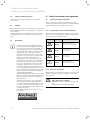
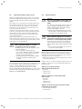
These instructions apply for the following only:
Unit type
Cylinder volume
Article number
VIH S GB 210/2 S
210 litres
0020115422
VIH S GB 260/2 S
260 litres
0020115425
VIH S GB 310/2 S
310 litres
0020115428
Table 1.1 Applicability of the instructions
> The article number of the unit is displayed
on the identification plate.
Instructions on commissioning, maintenance, and troubleshooting for auroSTOR 0020111119_02
3
1 Notes on the documentation
2 Safety instructions and regulations
1.5
Cylinder identification plate
The identification plate is attached to the cylinder
at the factory.
1.6
2
Safety instructions and regulations
2.1
Safety and warning information
When conducting installation and maintenance work,
observe the general safety instructions and the warning
notes which appear before each of the actions.
CE label
CE labelling shows that, based on the type overview, the
units comply with the basic requirements of the applicable directives.
The CE declarations of conformity can be viewed at the
manufacturer's premises and can be supplied if necessary.
2.1.1
Classification of action-related warnings
The action-related warnings are classified in accordance
with the severity of the possible danger using the following warning signs and signal words:
Warning sign
1.7
i
4
Signal word
Explanation
Danger!
Imminent danger to life or
risk of severe personal injury
Danger!
Risk of death from
electric shock
Warning!
Risk of minor
personal injury
Caution!
Risk of material or
environmental damage
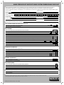
Benchmark
Vaillant Ltd. supports the Benchmark Initiative. You will find the Benchmark Logbook on
the last page of this instruction manual. It is
very important that this document be filled
out properly when installing, commissioning
and handing-over to the operator of the
installation. Installers should point out also
the service record section for completion following service calls to this appliance.
Benchmark places responsibilities on both
manufacturers and installers. The purpose is
to ensure that customers are provided with
the correct equipment for their needs, that it
is installed, commissioned and serviced in
accordance with the manufacturer’s instructions by competent persons approved at the
time by the Health and Safety Executive and
that it meets the requirements of the appropriate Building Regulations.
The Benchmark Checklist can be used to demonstrate compliance with Building Regulations
and should be provided to the customer for
future reference.
Installers are required to carry out installation, commissioning and servicing work in
accordance with the Benchmark Code of Practice which is available from the Heating and
Hot water Industry Council who manage and
promote the Scheme.
Visit "www.central heating.co.uk" for more
information.
a
e
a
b
2.1.2
Structure of warnings
Warning signs are identified by an upper and lower separating line and are laid out according to the following
basic principle:
a
Signal word!
Type and source of danger!
Explanation of the type and source of danger.
> Measures for averting the danger
Instructions on commissioning, maintenance, and troubleshooting for auroSTOR 0020111119_02
Safety instructions and regulations 2
2.2
Intended use
The Vaillant solar heating system has been constructed
using state-of-the-art technology in accordance with recognised safety regulations.
Nevertheless, there is still a risk of injury or danger of
death to the operator or others or of damage to the unit
and other property in the event of improper use or use
for which the unit is not intended.
These components of the Vaillant solar heating system
are not intended to be used by persons (including children) with limited physical, sensory or mental capabilities or insufficient experience and/or knowledge, unless
they are supervised by a person who is responsible for
their safety or have been instructed by this person on
how to use the unit.
Children must be supervised to ensure that they do not
play with the unit.
The purpose of the Vaillant solar heating system is to
provide a solar-supported hot water supply.
Vaillant auroSTOR VIH S GB 210/2 S, VIH S GB 260/2 S,
and VIH S GB 310/2 S solar cylinders are unvented, indirectly heated domestic hot water cylinders for solar
heating systems designed for use with gas-fired wallhung boilers as per GB standards for hot water supply
systems. The cylinders work with the pressure of the
water supply line and do not need a cold water tank for
their supply.
They are used only to supply potable water heated up to
80 ºC by means of a solar collector array. They may only
be used for this purpose. The cylinders can be used in
combination with a downstream gas-fired wall-hung
boiler for hot water production in accordance with
GB standards.
Any other use that is not specified in these instructions,
or use beyond that specified in this document shall be
considered improper use.
Any direct commercial or industrial use is also deemed
to be improper.
The manufacturer/supplier is not liable for any claims or
damage resulting from improper use. The user alone
bears the risk.
Intended use includes the following:
– observance of accompanying operating, installation and
servicing instructions for Vaillant products as well as for
other parts and components of the system.
– compliance with all inspection and maintenance conditions listed in the instructions.
Improper use of any kind is prohibited!
All installers should have a current ID card and registration number. The cylinder must be installed by a competent person approved at the time by the Health and
Safety Executive to the prevailing standards, installation
book and building regulations at the time of installation.
2.3
General safety instructions
Installation, commissioning, and maintenance
Installation and adjustment as well as service, maintenance and repair must be carried out by a competent
person approved at the time by the Health and Safety
Executive and be in accordance with the relevant
requirements of the Local Authority, Building Regulations, Building Regulations (Scotland), Building Regulations (Northern Ireland), and the bye-laws of the local
Water Undertaking.
All electrical wiring must be carried out by a competent
electrician and be in accordance with the current I.E.E.
Wiring Regulations.
> Make sure that the system has been planned in
accordance with technical regulations and all applicable
planning standards.
Risk of death due to lack of safety devices
A lack of safety devices (e.g. expansion relief valve,
expansion vessel) can lead to potentially fatal scalding
and other injuries, e.g. due to explosions.
The schematic drawings included in this document do
not show all safety devices required for correct installation.
> Install the necessary safety devices in the system.
> Inform the operator about the function and position of
the safety devices.
> Observe the applicable national and international laws,
standards and guidelines.
Safety information on the solar heating system
> Mount and operate the entire solar heating system in
accordance with the recognised technical regulations.
> Make sure that all valid health and safety regulations are
observed, especially for work on the roof. Always use fall
protection devices if there is a risk of falling. We recommend the use of a Vaillant safety belt. Observe the accident prevention regulations of the professional associations.
> Earth the solar circuit for potential equalisation and to
protect against overvoltage. Attach earthing pipe clamps
to the solar circuit pipes and connect the clamps to a
potential equalisation bar using 16 mm2 Cu cable.
At the end of these instructions there is a commissioning report which you must fill in and hand over to the
operator.
Instructions on commissioning, maintenance, and troubleshooting for auroSTOR 0020111119_02
5
2 Safety instructions and regulations
Cylinder safety information
Following an inspection, it was ascertained that this
product complies with the building regulations for closed
hot water cylinder systems and must not be changed or
rebuilt in any way.
> When replacing parts, only original replacement parts
from Vaillant Ltd. may be used.
The installation must be approved in accordance with
the building regulations.
> Installation plans must be disclosed to the relevant
authorities.
Important:
As stipulated in the manual "Handling Operations Regulations 1992", the weight of the unit exceeds that which
should be lifted by one person alone.
Electric potential equalisation
If you use an electric immersion heater in the cylinder,
the external voltage may build up electrical potential in
the water which can result in the electrochemical corrosion of the electric immersion heater.
If the solar cylinder is connected with pipes made of
non-metallic materials and is not earthed, corrosion
damage can occur.
> Make sure that both the hot water and cold mains inlets
are connected to the earth line by means of
an earth cable directly on the cylinder.
> You must also make sure that the electric immersion
heater is connected to the earth line via the earthing terminal.
If the solar heating system is in stagnation, hot steam
can escape from the expansion relief valve of the solar
pump unit, causing injury to persons. Escaping solar
fluid is visible in the collection canister.
> Connect the expansion relief valve to a collecting
container via a metal pipe.
> Position an air vent or an air separator system in such a
way that persons are not endangered by escaping steam.
> Install a hot water thermostat mixer in the system
to protect against scalding.
Preventing frost damage
You should not turn the gas-fired wall-hung boiler off
completely so that you can still use all of the safety
functions for your heating system. If you want to take
the unit out of operation for a relatively long period of
time in an unheated room at risk from frost, you must
completely drain the auroSTOR.
Avoiding damage caused by leaks
If there are leaks in the pipework, close off the cold
water stop valve on the safety assembly and notify a
competent person so that they can rectify the leaks.
Preventing damage due to unauthorised changes
to the unit
Changes to the supply lines, relief valve termination,
and expansion relief valve may only be carried out by
a competent person!
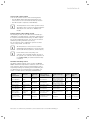
2.4
Overview of EU standards
Risk of scalding and damage from escaping hot or cold
water.
2.4.1
General information on solar heating system
> If you use plastic pipes for the hot or cold water connection of the unit, you must only use pipes which are temperature-resistant up to 95 °C under a pressure of 1.0
MPa (10 bar).
EN ISO 9488
Solar heating system and components, terminology
(ISO/DIS 9488; 1995)
Improper use and/or the use of unsuitable tools may
result in damage (e.g. water leaks).
> Always use a suitable open-end wrench (spanner) to tighten or undo threaded connections. Do not use pipe wrenches, extensions, etc.
If the water does not satisfy the standards for water
quality in the UK with a maximum chloride content of
250 mg/l, this may result in corrosion damage to the
cylinder.
> Only use the cylinder to heat potable water.
EN 12975-1
Solar heating systems and components; Collectors,
Part 1: General requirements
EN 12975-2
Solar heating systems and components; Collectors;
Part 2: Testing methods
EN 1991-2-3
Eurocode 1 – Basis of design and actions on structures,
Part 2–3: Actions on structures - Snow loads
Avoiding burns and scalds
> Install and replace collectors or collector parts on very
cloudy days. Only carry out installation work
in the early morning or in the evening on sunny days or
cover the collector.
> Fill and flush the solar heating system when the collectors are cold. Cover the collectors while doing so.
6
EN 12976-1
Solar heating systems and components;
Factory made systems - Part 1: General requirements
EN 12976-2
Solar heating systems and components;
Factory made systems - Part 2: Testing methods
Instructions on commissioning, maintenance, and troubleshooting for auroSTOR 0020111119_02
Safety instructions and regulations 2
ENV 12977-1
Solar heating systems and components;
Custom built systems,
Part 1: General requirements
ENV 12977-2
Solar heating systems and components;
Factory made systems,
Part 2: Testing methods
ISO 9459-1: 1993
Solar heating – Domestic water heating systems – Part 1:
System rating procedures using indoor test methods
ISO/TR 10217
Solar energy; Water heating system; Guideline for material selection with reference to internal corrosion
2.4.2
Cylinder and cylinder assembly
Pressure equipment directive 97/23/EC
Directive of the European Parliament and Council
of 29th May 1997 for the approximation of the laws
on pressure equipment of the Member States
EN 12977-3
Solar heating systems and components;
Custom built systems,
Part 3: Performance characterisation of domestic
hot water cylinders
EN 12897:2006
Water supply - specification for indirectly heated
unvented (closed) domestic hot water cylinders
EN 806-1
Specifications for installations inside buildings conveying
water for human consumption - Part 1: General
EN 1717
Protection against pollution of potable water installations and general requirements of devices to prevent
pollution by backflow
EN 60335-2-21
Safety of household and similar electrical appliances;
Part 2: Particular requirements for storage water heaters (domestic hot water cylinders and hot water boilers)
(IEC 335-2-21: 1989 and supplements 1; 1990 and 2; 1990,
modified)
Lightning protection
ENV 61024-1
Protection of structures against lightning – Part 1:
General principles (IEC 1024-1: 1990; modified)
BS 6651: Code of practice for protection of structures
against lightning
2.5
Regulations for Great Britain
2.5.1
Technical Guidance
The system must be installed in accordance with all relevant and applicable national regulations, and must be
installed to suit site conditions.
Observe all national regulations, including:
–
–
–
–
–
–
Working at Heights Regulations 2005
Health and Safety at Work Act 1974
Electricity at Work Regulations 1989
IEE Wiring Regulations BS 7671
Lightning protection requirements
Equipotential bonding of electrical installations.
2.5.2
Related documents
The installation of the solar system must be in accordance with the relevant requirements of Health and
Safety Document No. 635 (The Electricity at Work Regulations 1989), BS7671 (IEE Wiring Regulations) and the
Water Supply (Water Fitting) Regulations 1999, or The
Water Bylaws 2000 (Scotland). It should also be in
accordance with the relevant requirements of the Local
Authority, Building Regulations, The Building Regulations
(Scotland), The Building Regulations (Northern Ireland)
and the relevant recommendations of the following
British Standards:
BS EN 806: Specification for installations inside buildings conveying water for human consumption
BS 6700: Services supplying water for domestic use
within buildings and their curtilages.
BS. 5449 Forced circulation hot water central heating
systems for domestic premises. Note: only up to 45 kW.
BS. 6880 Low temperature hot water heating systems
of output greater than 45 kW.
Part 1 Fundamental and design considerations.
Part 2 Selection of equipment.
Part 3 Installation, commissioning and maintenance.
BS 6114: Expansion vessels using an internal diaphragm
for unvented hot water supply systems
BS. 4814 Specification for: Expansion vessels using an
internal diaphragm, for sealed hot water heating systems.
Unvented hot water systems must comply with building
regulation G section 3.
Instructions on commissioning, maintenance, and troubleshooting for auroSTOR 0020111119_02
7
2 Safety instructions and regulations
3 System description
2.5.3
Regulations for the prevention of accidents
When carrying out works such as solar installation work
it is necessary to do so in a safe and workman like manner, taking due care of any aspects of the works that
could result in injuries to person in or about the building
as well as workers, passers by and the general public at
large. To that end these works must conform, but not be
limited to, the current regulations in force such as the
following
Health and Safety at Work act 1974
Work at Height Regulations 2005.
Electricity at Work Regulations 1989
All necessary Building Regulations.
Work should be preceded by a risk assessment covering
all aspects of health and safety risks, or training requirements that can reasonably be foreseen to be
associated with the work. All scaffolding in the UK, other
than prefabricated (zip-up) scaffold towers, must be
designed and constructed by a vetted contractor, and
have suitable kick boards, hand rails and where appropriate netting. Areas around the scaffolding should be
zoned off and marked with suitable warning signs to a
suitable distance to protect persons from falling objects.
Workers should have available and use personal protective equipment as necessary. This would include equipment such as fall protection systems, safety gloves,
goggles, dust masks as well as any specialised equipment that may be in use such as lifting and handling
equipment.
The completed works shall comply with all necessary
BS EN Standards and Codes of practice as well as Building control or planning requirements and be confirmed
where necessary by notification to building control or
the appropriate competence based notification body.
8
3
3.1
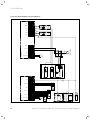
System description
Design and function of solar heating system
The solar heating system consists of four main components:
– The collectors, which absorb the solar radiation and
make it useful
– The solar controller, which monitors, displays, and controls all system functions
– The solar pump unit, which is responsible for transporting the solar heat
– The solar cylinder
The Vaillant solar heating system is a closed hydraulic
system in which heat is transferred to the cylinder via
the heat exchanger with the help of the system's special
heat transfer fluid.
On days when the solar radiation is not sufficient to heat
the hot water in the cylinder, the cylinder water must be
reheated using a heating system. This can take place
using a gas-fired wall-hung boiler or an electric immersion heater.
Instructions on commissioning, maintenance, and troubleshooting for auroSTOR 0020111119_02
System description 3
6
7
8
9
10
C
D
DHW
12
2
3
M
4
11
1
M
M
5
A
B
5
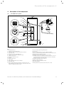
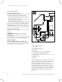
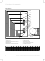
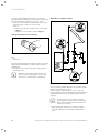
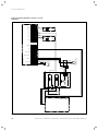
Fig. 3.1 System for solar hot water production
Key
1 Gas-fired wall-hung boiler
2 Cylinder
3 Two port motorised valve (230 V, supplied with cylinder)
4 Electric immersion heater
5 Two port motorised valve (230 V)
6 Collector (tube collector with top connections (example) or flat
collector with top and bottom connections)
7 Solar pump unit
8 Solar protection and expansion vessel (Combined unit)
9 Collection canister for solar fluid
10 Automatic air separator system
11 Hot water expansion vessel
12 Thermostat mixer
A Primary heater flow
B Primary heater return
C Solar flow
D Solar return
DHW Hot water
Instructions on commissioning, maintenance, and troubleshooting for auroSTOR 0020111119_02
9
3 System description
i
i
The collection canister for solar fluid collects
escaping solar fluid. The solar fluid must not
reach the drainage system.
i
If a cylinder is fitted very high up in the building,
negative pressure may form in the cylinder.
Under such circumstances, the competent person must decide whether an anti-vacuum valve
is required in order to prevent damage to the
cylinder. If, as a result of draining or thermal
contraction of the drinking water, the negative
pressure in the cylinder is too high, an anti-vacuum valve ensures pressure compensation as a
result of air flowing into the cylinder.
For the supply and return lines in the solar circuit, use insulated stainless steel pipes, e.g. the
Vaillant Solar flexible pipe that is included in the
scope of delivery of a Vaillant Solar set. Alternatively, you can also use copper pipes with press
fittings and suitable insulation. Soft solder connections are not suitable for solar piping.
3.2
If you use an eBUS-compatible Vaillant gas-fired wallhung boiler, you can use a Vaillant Control Centre for the
wiring.
If you are using a non-eBUS-compatible Vaillant gasfired wall-hung boiler or a third-party boiler, you can
use a standard cabling box.
Section 6.8 of these instructions describes the electrical
wiring of the system in detail.
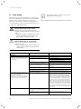
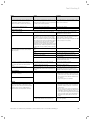
3.3
A solar expansion vessel compensates for pressure
fluctuations in the solar circuit.
A solar protection vessel protects the expansion vessel
from excessive temperatures in the solar circuit. We recommend installing a protection vessel.
All Vaillant solar sets contain a combined solar protection and solar expansion vessel (8).
10
Hot water temperature regulation
You can control the hot water temperature in the top
third of the cylinder using an auroMATIC VRS 560/2 or a
calorMATIC VRC 470 with VR 68/2 and VR 61/2 or with a
separate hot water controller.
a
The collector (6) converts solar energy into heat and
transfers the heat energy to a frost-protected solar fluid.
Using the pipe system, the solar pump of the solar pump
unit (7) conveys the heat from the collector to the bivalent cylinder (2). The solar pump unit is controlled by
the solar controller.
The solar controller switches the solar pump on and off
as soon as the temperature difference between the collector and cylinder exceeds or falls below the preset
value. If the solar energy is not sufficient for requirements, the controller activates the gas-fired wall-hung
boiler (1) to reheat the top third of the cylinder to the
set hot water temperature value. The water in the cylinder can also be reheated using the electric immersion
heater installed at the factory.
Electrical wiring
3.4
Danger!
Risk of burns and scalds!
Water at a temperature of more than 60 ºC
could be delivered to the hot water draw-off
points.
> Install a hot water thermostat mixer in
the hot water pipe to provide effective
scald protection.
> Set the hot water thermostat mixer to
less than 60 ºC and check the temperature at
a hot water draw-off point.
Heating control
If you are using an eBUS-compatible Vaillant gas-fired
wall-hung boiler, you can control the heating using a
programmable Vaillant VRT room thermostat or a VRC
weather compensator.
If you are using a non-eBUS-compatible Vaillant gasfired wall-hung boiler or a third-party boiler, you can use
a Vaillant VRT 30 room thermostat or one of the room
thermostats commonly available on the market.
Instructions on commissioning, maintenance, and troubleshooting for auroSTOR 0020111119_02
Description of the components 4
4
4.1
Description of the components
auroSTOR solar cylinder
1
26
2
3
25
21
22
24
4
23
7
20
6
5
9
19
3
4
2
5
8
1
3
18
17
16
15
14
13
10
12
11
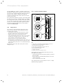
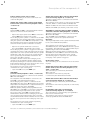
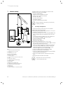
Fig. 4.1 auroSTOR solar cylinder function elements
Key
1 Hot water draw off
2 Expansion relief valve (6.0 bar)
3 Pressure reducing valve (3.5 bar) with line strainer
4 Cold water inlet
5 Pressure-controlled cold water inlet
6 Connection for hot water expansion vessel
7 Cylinder connection
8 Hot water expansion vessel
9 Tundish
10 Cylinder drain valve
11 Solar return
12 Solar yield temperature sensor (Ertrag)
13 Cold water inlet
14 Solar circuit thermal cut-out (TCO), set to 80ºC, to be connected with the solar pump in order to isolate this heat source
if there is a fault in the solar control.
15 Solar circuit cylinder dry pocket (SP 2)
16 Solar flow
17 2-pole isolating switch for electric immersion heater
18 Electric immersion heater with thermostat and thermal cut-out
19 Return (gas-fired wall-hung boiler)
20 Primary heating circuit cylinder dry pocket (SP 1)
21 Primary heating circuit thermal cut-out, set to 80ºC, to be connected to the two port motorised valve in order to isolate the
primary heat source if a fault occurs.
22 Cylinder thermostat (20 °C to 65 °C)
23 Two port motorised valve
24 Flow line (gas-fired wall-hung boiler)
25 Secondary return
26 Temperature and pressure relief valve (90 °C, 7 bar)
Instructions on commissioning, maintenance, and troubleshooting for auroSTOR 0020111119_02
11
4 Description of the components
The auroSTOR solar cylinder is available in three sizes:
210, 260, and 310 litres. The cylinder is made from stainless steel and is insulated with EPS with heat radiation
absorbers. The cylinder is supplied along with all
required cold and hot water control devices and a two
port motorised valve.
The cylinder works with the pressure of the water supply
line and does not need a cold water tank for its supply.
The cylinder has hot and cold water inlets with a diameter of 22 mm. To enable the cylinder to work as well as
possible, a cold water supply with a dynamic pressure
and flow rate that are appropriate for the system is
required (¬ section 6.6.1).
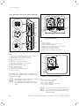
4.1.2
Cylinder operating elements
1
8
7
2
3
4
3
2
5
4.1.1
1
Safety devices
6
The cylinder is delivered with all safety and control
devices for the operation of the unvented domestic
hot water supply system:
–
–
–
–
Temperature and pressure relief valve (90 °C, 7 bar)
Pressure reducing valve (3.5 bar) with line strainer
Expansion relief valve (one-way valve, 6.0 bar)
Solar circuit thermal cut-out, set to 80 ºC, to be connected with the solar pump in order to isolate this heat
source if there is a fault in the solar control.
– Thermal cut-out for electric immersion heater
– Primary heating circuit thermal cut-out, set to 80 ºC, to
be connected to the two port motorised valve in order to
isolate the primary heat source if a cylinder thermostat
fault occurs.
The thermal cut-out and other safety devices must
always be used.
5
4
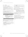
Fig. 4.2 Cylinder operating elements
Key
1 Cover cap for reset button for primary heating circuit TCO
2 Primary heating circuit temperature controller
3 Electric immersion heater cover
4 Cover cap for reset button for solar circuit TCO
5 Solar circuit thermal cut-out (TCO)
6 Electric immersion heater
7 Cylinder thermostat
8 Primary heating circuit thermal cut-out
The following are pre-mounted at the factory for the
auroSTOR solar cylinder:
– Cylinder thermostat (7) and primary heating circuit thermal cut-out (8)
– Electric immersion heater (6) with thermal cut-out and
cylinder thermostat
– Solar circuit thermal cut-out (5)
The cylinder must be properly wired in order to comply
with G3 building regulations.
12
Instructions on commissioning, maintenance, and troubleshooting for auroSTOR 0020111119_02
Description of the components 4
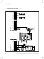
1
Electric immersion heater
1
3
2
3
3
4
2
2
3
5
1
3
4
3
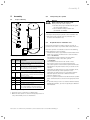
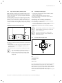
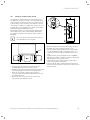
Fig. 4.4 Electric immersion heater operating elements
Fig. 4.3 Connection diagram for solar pump
Key
1 Solar controller or solar module
2 Terminal strip for series circuit to solar pump via TCO solar
circuit
3 Solar pump
4 Solar circuit thermal cut-out
i
You must connect the solar pump to the solar
controller via the solar circuit thermal cut-out
(5) (¬ section 6.8). The thermostat switches the
solar pump off if the hot water temperature in
the cylinder exceeds 80 ºC. Set the maximum
cylinder temperature (MAXT 1)
to 75 °C (factory setting) on the auroMATIC
VRS 560 solar controller.
Key
1 Electric immersion heater temperature controller
2 Electric immersion heater TCO reset button
3 Electric immersion heater
The cylinder is equipped with an additional electric
immersion heater (3) with a heating output of 3 kW. The
electric immersion heater is located behind the top front
cladding. The electric immersion heater is designed for
use in unvented cylinders and has a thermostat with a
temperature controller (1) and a thermal cut-out (TCO)
with a reset button (2).
i
If you need to make a replacement, you must
use the correct electric immersion heater with a
thermal cut-out for overheating protection. The
seal of the electric immersion heater must also
always be replaced. Use only original replacement parts from Vaillant Ltd.
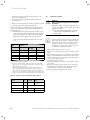
Setting the hot water temperature
You can set the hot water temperature by pointing the
arrow on the temperature controller (1) of the electric
immersion heater to a number between 1 and 5. The following table contains the approximate hot water temperature for each of the five settings.
Setting
1
Hot water temperature
20 °C
2
35 °C
3
45 °C
4
60 °C
5
68 °C
Table 4.1 Setting the hot water temperature
Instructions on commissioning, maintenance, and troubleshooting for auroSTOR 0020111119_02
13
4 Description of the components
4.2
Solar fluid
4.2.1
Properties of solar fluid
4.2.2 Solar circuit frost and corrosion protection
system
This information applies to Vaillant solar fluid
(20 l canister: article number 302498 and 10 l canister:
article number 302363).
Vaillant solar fluid is a ready-mixed frost and
corrosion protection agent, consisting of approximately
45% propylene glycol with anti-corrosion inhibitors and
55% water.
Vaillant solar fluid is extremely temperature-resistant
and can be used in conjunction with Vaillant tube collectors and Vaillant flat collectors.
The solar fluid also has a high heat capacity.
The inhibitors provide reliable corrosion protection when
different types of metal are used (mixed installations).
b
i
Caution!
Risk of damaging the collectors and
other system parts if unsuitable solar
fluid is used.
If you mix the solar fluid with water or
another liquid, frost and corrosion protection cannot be ensured.
> Never mix the solar fluid with water
or another liquid.
In order to reliably protect the solar heating system
from frost in winter, you must fill the entire system with
undiluted Vaillant solar fluid.
i
Filling the solar heating system with Vaillant
solar fluid provides frost protection up to
approx. -28 ºC.
Even at outside temperatures of lower than
-28 ºC, frost damage does not occur straight
away since the explosive effect of the water is
distributed. Check the frost protection effect
after filling the system and then once every year.
We recommend the Vaillant refractometer for quick and
simple checking. A classic Vaillant frost protection tester
can be used for this.
See the enclosed operating instructions.
4.2.3
Cylinder frost protection
If you want to put a cylinder out of operation where it
may be at risk from frost, you must drain it completely.
It is drained at the cold water inlet with a T-piece with
tap to be provided by the installer.
Any heat exchangers not filled with solar fluid in rooms
which are at risk of frost must also be completely
drained.
Do not use any other frost protection agents or
inhibitors for the Vaillant solar heating system.
Only Vaillant's solar fluid is permitted for use
with the system.
Vaillant solar fluid is infinitely durable in hermetically
sealed containers.
It is not dangerous if it comes into contact with the skin.
Eye contact only causes minor irritations, you should
nevertheless immediately wash your eyes.
Pay attention to the safety data sheet
(¬ section 4.2.4).
14
Instructions on commissioning, maintenance, and troubleshooting for auroSTOR 0020111119_02
Description of the components 4
4.2.4 Safety data sheet for Vaillant solar fluid
1)
1a)
1b)
1c)
1d)
2)
2a)
Name of substance/preparation and company
details:
Trade name:
Vaillant ready-mixed solar fluid
Use:
Heat transfer fluid for solar heating systems
Company:
Vaillant GmbH
Berghauser Str. 40
42859 Remscheid, Germany
Tel. 0049 (0) 2191 18-0, Fax 0049 (0) 2191 18-2810
Emergency information:
your local poison information centre
(see directory assistance or telephone directory).
Possible dangers:
Special danger indications for people and the
environment: Not required!
3)
3a)
Composition/information on ingredients:
Chemical nature:
Aqueous solution of 1.2-propylene glycol
(CAS no.: 57-55-6) with corrosion inhibitors.
3b)
Hazardous ingredients:
1,1’-iminodipropan-2-ol
content (w/w): > 1 % - < 3 %, CAS no.: 110-97-4
EC no.: 203-820-9, hazard symbol: Xi
INDEX no: 603-083-00-7, R phrases: 36
If hazardous ingredients are named, the wording for
the hazard symbols and R phrases will be
provided in Point 16.
First aid measures:
General information:
Remove dirty clothes.
4b) After inhalation:
Discomfort after inhaling fumes/aerosol:
fresh air, help from a doctor.
4c) After skin contact:
Wash off with water and soap.
4d) After contact with the eyes:
Thoroughly rinse out with running water
for at least 15 minutes with the eyes open.
4e) After swallowing:
Rinse mouth and drink lots of water.
4f) Information for the doctor:
Treatment of symptoms (decontamination,
vital function), no specific antidote known.
5)
5a)
5b)
5c)
5d)
6)
6a)
6b)
Firefighting measures:
The product is not flammable. Surrounding fire can be
combated with sprayed water, dry extinguishers, alcohol-resistant foam, and carbon dioxide (CO2).
Special dangers: Fumes which are detrimental to
health. Formation of smoke/mist. The specified substances/substance groups may be released in the event
of a fire.
Special protection equipment: Wear a breathing apparatus which is independent of the circulating air in the
event of a fire.
Further information: The dangers depend on the burning substances and the fire conditions. Polluted fire
water must be disposed of according
to local official regulations.
Measures in the case of accidental release:
Precautions to protect persons:
No particular measures required.
Measures to protect the environment:
Contaminated water/fire water must be withheld.
It must not be discharged into bodies of water without
being pre-treated first (in a biological waste water
treatment plant).
6c)
Cleaning/collection procedure:
Contain any escaped material and cover with large
quantities of sand, soil, or another absorbing material;
then sweep enthusiastically to promote absorption.
Fill the mixture into containers or plastic bags and
take away for disposal.
Wash away small amounts (splashes) with large quantities of water. For large quantities, pump out the product, collect it up and take it away for disposal. If larger quantities may have entered the drainage system
or water bodies, contact the responsible water authorities.
7)
7a)
Handling and storage:
Handling:
No particular measures required.
Fire and explosion protection:
No particular measures required.
Storage:
Containers must be closed so that they are airtight
and stored in a dry location.
Galvanised storage containers must not be used.
4)
4a)
7b)
7c)
Instructions on commissioning, maintenance, and troubleshooting for auroSTOR 0020111119_02
15
4 Description of the components
8)
8a)
8b)
9)
Exposure prevention and personal protective equipment:
Personal protective equipment:
Breathing protection: Breathing protection
if vapours/aerosols are released.
Hand protection: chemical-resistant protective gloves
(EN 374).
Recommended: Nitrile rubber (NBR), protection class
6.
Owing to the large variety of types, observe the
manufacturers' operating instructions.
Eye protection: Safety glasses with lateral protection
(framed glasses) (EN 166)
General protection and hygiene measures:
The usual precautions for working with chemicals
must be observed.
Physical and chemical properties:
Form: Liquid.
Colour: Fluorescent red.
Smell: Product-specific.
Freezing point: Approx. -25 ºC (ASTM D 1177)
Solidification point: Approx. -31 ºC (DIN 51583)
Boiling point: >100 ºC (ASTM D 1120)
Flashpoint: N/A
Lower explosion limit: 2.6 vol% (propylene glycol)
Upper explosion limit: 12.6 vol% (propylene glycol)
Ignition temperature: N/A
Vapour pressure (20° C): 20 mbar
Density (20 ºC): Approx. 1,030 g/cm3 (DIN 51757)
Solubility in water: Completely soluble
Solubility in other solvents: Soluble in polar
solvents
pH value (20 ºC): 9.0 - 10.5 (ASTM D 1287)
Viscosity (kinematic at 20 ºC): Approx. 5.0 mm2/s (DIN
51562)
10) Stability and reactivity:
10a) Substances to be avoided:
Strong oxidants
10b) Hazardous reactions:
No dangerous reactions if the storage and handling
regulations/notes are observed
10c) Hazardous decomposition products:
No dangerous decomposition products if the storage
and handling regulations/notes are observed.
11)
16
Toxicology information:
LD50/oral/rat: > 2000 mg/kg
Primary skin irritation (rabbits):
Non-irritant (OECD Directive 404).
Primary mucous membrane irritation (rabbits):
Non-irritant (OECD Directive 405).
11a)
Additional information:
The product has not been checked. The statements
are derived from the properties of the individual components.
12) Ecology information:
12a) Ecotoxicity:
Fish toxicity: Leuciscus idus/LC50 (96 h):
> 100 mg/l
Aquatic invertebrates: EC50 (48 h): > 100 mg/l
Aquatic plants: EC50 (72 h): > 100 mg/l
Micro-organisms/effect on activated sludge:
DEV-L2 > 1000 mg/l. If low concentrations are properly introduced into adapted biological waste water
treatment plants, no disturbances of the degradation
activity of activated sludge are to be expected.
12b) Assessment of aquatic toxicity:
The product has not been checked. The statements
are derived from the properties of the individual components.
12c) Persistence and degradability:
Details regarding elimination:
OECD 301A test method (new version)
Analysis method: DOC acceptance
Degree of elimination: > 70 %
Assessment: easily biodegradable.
13) Information on disposal:
13a) Disposal:
When disposing of the fluid, you must observe all local
regulations, e.g. take the waste to a suitable dump or
incinerator. For quantities of less than
100 l, contact the local city cleaning department
or mobile environmental service.
13b) Contaminated packaging:
Uncontaminated packaging can be reused. Packaging
that cannot be cleaned must be disposed of in the
same way as the material.
14)
Information on transport:
Not dangerous goods in terms of the transport
regulations.
(ADR RID ADNR IMDG/GGV, see ICAO/IATA)
15) Legislation:
15a) European Union legislation (labelling)/national
regulations:
EU Directive 1999/45/EC
(Dangerous Preparations Directive):
No labelling obligation
15b) Other legislation:
Water hazard class 1: Low hazard to water
(Germany, VwVwS of 17.05.1999).
Instructions on commissioning, maintenance, and troubleshooting for auroSTOR 0020111119_02
Description of the components 4
16)
Other information
Complete wording for hazard symbols and R phrases
if stated in "Hazardous ingredients"
in section 3: Xi: Irritant. R36: Irritates the eyes.
All information which has been changed since the last
edition is identified by means of a vertical slash on
the left-hand side of the passage in question.
In such cases, the information shown in older editions
loses its validity.
The safety data sheet is intended to communicate the
most important physical, safety-related, toxicological,
and ecological information to be observed when working with chemicals and preparations and to provide
recommendations for safe use and/or storage, handling, and transport. No liability is assumed for damage
in connection with the usage of this information or
the usage, application, adaptation or processing of the
products described here. This does not apply as long
as we, our statutory agents or assistants are liable in
the event
of intention or gross negligence. No liability is assumed for indirect damage.
This information has been compiled to the best of our
knowledge and conscience according to our current
state of knowledge. No guarantee can be made for
product properties.
17)
Valid as of: 01.01.2009
Created by: Vaillant GmbH.
4.3
System configuration
The Vaillant solar heating system enables various system configurations and control types in accordance with
the connection wiring diagrams 1 to 6 (¬ section 6.8).
i
Single-channel eBUS controllers are not suitable
for this system configuration.
Wiring
If you use an eBUS-compatible Vaillant gas-fired wallhung boiler, you can use one of the Vaillant Control Centres to wire the system.
For all other gas-fired wall-hung boilers, you can use a
standard cabling box.
4.3.1
Vaillant controllers and their basic functions
VRS 560/2 solar controller
The auroMATIC 560/2 solar controller is a differential
temperature-controlled control set for solar-aided hot
water production with demand-controlled primary heating for Vaillant gas-fired wall-hung boilers.
The control set is a fully equipped system for solar heating systems with a collector array and cylinder.
If a solar yield temperature sensor (VR 10, supplied with
controller) is connected, the solar yield can be recorded.
Control Centre
A Vaillant Control Centre provides a system solution
which allows the Vaillant dual-channel eBUS controller
(low-voltage) to be used in the English market with
valves and domestic hot water cylinders with conventional 230 V cylinder thermostats.
The Control Centre sends the information on the heat
requirement of the cylinder to the Vaillant ecoTEC gasfired wall-hung boiler. The gas-fired wall-hung boiler
decides whether a hot water requirement needs to be
met and sends a signal to control the 230 V valves via
the Control Centre.
The gas-fired wall-hung boiler can thus hold different set
temperature values for heating mode and for hot water
handling.
A Control Centre can be used to integrate commonly
available 230 V S plan or Y plan components into the
Vaillant eBUS system.
VRC weather compensator
(VRC 430, VRC 430f, VRC 470, VRC 470f)
A VRC controller controls the solar heating system in a
weather-compensated and time-dependent manner with
or without hot water production/a circulation pump in
conjunction with a Vaillant gas-fired wall-hung boiler
with an eBUS interface and the Vaillant VR 68/2 solar
module.
Solar module VR 68/2
The VR 68/2 solar module integrates a solar heating system into the control concept of a VRC controller. In conjunction with a VRC controller , various solar heating
system configurations can be implemented and the solar
yield recorded. You can combine the VR 68/2 solar module with a VR 61/2 mixer module in a solar heating system.
VR 61/2 mixer module
The VR 61/2 mixer module is a system component which
controls a cylinder charging circuit or circulation pump
in conjunction with a VRC controller.
You can use the VR 61/2 mixer module to control a solar
heating system for the heating of potable water in conjunction with a VRC controller and the VR 68/2 solar module.
Instructions on commissioning, maintenance, and troubleshooting for auroSTOR 0020111119_02
17
4 Description of the components
4.3.2
Control functions
Hot water temperature control
The hot water temperature in the top half of the cylinder
can be controlled in one of the following ways:
Kol 1
– Vaillant auroMATIC VRS 560/2 solar controller or
– using one of the Vaillant Control Centre‘s with the Vaillant dual-channel eBUS controller
– Vaillant VRC weather compensator with VR 61/2 mixer
module and VR 68/2 solar module or
– using the cylinder thermostat in conjunction with a timer.
1
230 V~
If you are using a controller by a third-party manufacturer, you use this controller to adjust the hot water
temperature. In this case, the Vaillant controller (e.g.
auroMATIC 560/2) acts only as a solar controller and
only controls the temperatures for solar water heating.
2
7
Solar circuit control system
The solar circuit can be controlled in one of the following ways:
3
6
VRS 560/2
(connection wiring diagrams 1, 2, 3, 4, and 6,
¬ section 6.8)
The lower cylinder sensor (SP 2) and the solar yield
temperature sensor are connected up to the VRS 560/2.
The solar pump is controlled via the VRS 560/2.
B
SP 1
4
C
D
VRC with VR 68/2
(connection wiring diagram 5, ¬ section 6.8)
The lower cylinder sensor (SP 2) and the solar yield
temperature sensor are connected up to the VR 68/2.
The solar pump is controlled via a VRC.
A
SP 2
5
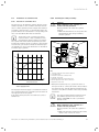
Fig. 4.5 Temperature differential control of solar pump
Key
1 Solar controller or solar module
2 Gas-fired wall-hung boiler
3 Solar cylinder
4 Solar circuit thermal cut-out
5 Solar yield temperature sensor
6 Solar pump
7 Solar pump unit
Kol 1 Collector sensor for flow line collector temperature
SP 1 Cylinder sensor for upper cylinder temperature
(primary heating circuit/standby section)
SP 2 Cylinder sensor for lower cylinder temperature (solar circuit)
A Primary heater flow
B Primary heater return
C Solar flow
D Solar return
Temperature differences, not absolute temperature values, are important for the operation of solar heating
systems. For this reason, solar heating systems are controlled via temperature differential controllers.
Integrated temperature sensors record the temperature
difference between the collector and the cylinder.
If the temperature difference (Kol 1 – SP 2) is larger than
7 K, the solar heating system's solar pump is switched on.
If the temperature difference (Kol 1 – SP 2) is smaller
than 3 K, the solar heating system's solar pump is
switched off.
18
Instructions on commissioning, maintenance, and troubleshooting for auroSTOR 0020111119_02
Description of the components 4
Primary heating circuit control system
The primary heating circuit can be controlled in one
of the following ways:
Vaillant dual-channel eBUS controller with Vaillant
Control Centre (connection wiring diagrams 1 and 2,
¬ section 6.8)
Important:
Terminals NTC and CYL. of the Vaillant Control Centre
may not be connected at the same time.
– Option 1: The upper cylinder sensor NTC is connected to
terminal NTC of the Vaillant Control Centre.
The recharging of the cylinder is controlled via the eBUS
controller. Here, the cylinder temperature is measured
using the cylinder sensor NTC. The temperature is compared with the target value programmed in the eBUS
controller and the cylinder is reheated if necessary.
– Option 2: The cylinder thermostat is connected
up to terminal CYL. of the Vaillant Control Centre.
The recharging of the cylinder is triggered via the cylinder thermostat. If the actual value falls below the target
temperature set on the cylinder thermostat, the cylinder
thermostat is shut. The closing of the cylinder thermostat is registered by the Vaillant Control Centre and
passed onto the eBUS controller.
The eBUS controller releases the recharging of the
cylinder for the programmed primary heating times:
The primary heating device activates and the Vaillant
Control Centre switches the zone valves into the correct
position for the recharging of the cylinder.
The required zone valve position differs depending
on whether the S plan is being used:
– S plan: Valve CH closed, valve DHW open.
VRS 560/2
(connection wiring diagrams 3 and 4, ¬ section 6.8)
The upper cylinder sensor is connected to the terminal
SP 1 of the VRS 560/2.
The output EP of the VRS 560/2 is connected to the
input CYL. of the Vaillant Control Centre.
The recharging of the cylinder is controlled via the
VRS 560/2. Here, the sensor SP 1 measures the cylinder
temperature. The temperature is compared with the programmed target value in the VRS 560/2.
Within the primary heating times programmed in the
VRS 560/2, the contact EP is closed if the actual value
falls below the target temperature for the cylinder.
The closing of the contact EP is registered by the
Vaillant Control Centre and the recharging of the cylinder is triggered: The primary heating device activates
and the Vaillant Control Centre switches the zone valves
into the correct position for the recharging of the cylinder.
The required zone valve position differs depending
on whether the S plan is being used:
Vaillant dual-channel eBUS controller with VR 68/2
(connection wiring diagram 5, ¬ section 6.8)
The upper cylinder sensor is connected to the terminal
SP 1 of the VR 68/2.
The recharging of the cylinder is controlled via the eBUS
controller, which is connected with the VR 68/2 and
VR 61/2 via eBUS. The zone valves are switched via the
VR 61/2 (valve DHW open, heating circuit valve closed).
VRS 560/2 in conjunction with non-eBUS-compatible
controllers (connection wiring diagram 6, ¬ section 6.8)
The upper cylinder sensor is connected to the terminal
SP 1 of the VRS 560/2.
The output EP of the VRS 560/2 is connected to the
wiring of the S plan via the cylinder thermostat.
Important:
The target temperature on the cylinder thermostat must
be set to the maximum temperature!
The recharging of the cylinder is controlled via the
VRS 560/2. Here, the sensor SP 1 measures the cylinder
temperature. The temperature is compared with the programmed target value in the VRS 560/2.
Within the primary heating times programmed in the
VRS 560/2, the contact EP is closed if the actual value
falls below the target temperature for the cylinder.
The switching signal is coupled into an S plan and the
recharging of the cylinder is triggered.
Room heating control
The room heating can be controlled in one of the following ways:
Vaillant dual-channel eBUS controller with Vaillant
Control Centre (connection wiring diagrams 1, 2, 3,
and 4, ¬ section 6.8)
The room heating is controlled by the Vaillant
eBUS controller.
The actuation of the valves (S plan plan)
is controlled by the Vaillant Control Centre.
Vaillant dual-channel eBUS controller with VR 61/2
(connection wiring diagram 5, ¬ section 6.8)
The room heating is controlled by the Vaillant eBUS
controller.
The actuation of the valves (S plan plan) is controlled by
the VR 61/2.
Programmable timer and room thermostat
(connection wiring diagram 6, ¬ section 6.8)
The room heating is controlled using a programmable
timer and a room thermostat.
The actuation of the valves (S plan) is realised
via the programmable timer and DHW timer.
– S plan: Valve CH closed, valve DHW open.
Instructions on commissioning, maintenance, and troubleshooting for auroSTOR 0020111119_02
19
4 Description of the components
4.3.3
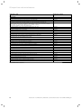
Technical data of the auroSTOR solar cylinder
Unit
Total capacity
Actual capacity
Hot water capacity (upper coil)
Hot water capacity (solar coil)
Dedicated solar volume
Maximum supply pressure to pressure reducing valve
Rated pressure of cylinder
Maximum operating pressure of heating coil
Maximum operating pressure of solar coil
Operating pressure
Pressure limiting valve
Expansion relief valve
Temperature and pressure relief valve
Charge pressure of hot water expansion vessel
Maximum temperature of heating circuit
Maximum temperature of potable hot water
Maximum temperature of solar fluid
Standing heat loss
Heat up time according to EN 12897
Recovery time (70% capacity)
Primary heat exchanger performance
Flow rate for primary heat exchanger performance
Primary heat exchanger pressure drop
Primary heat exchanger volume
Primary heat exchanger surface area
Heat up time according to EN 12897 (solar)
Solar heat exchanger performance
Flow rate for solar heat exchanger output
Solar heat exchanger pressure drop
Solar heat exchanger volume
Solar heat exchanger surface area
Dimensions
Height
Height with hot water draw off
Topple measure
Diameter
Depth
Net weight
Weight (full)
Connections
Cold water inlet
Hot water draw off
Balanced pressure cold water outlet
Secondary return
Primary heater flow
Primary heater return
Solar flow
Solar return
Primary heating circuit cylinder dry pocket size
Solar circuit cylinder dry pocket size
VIH S GB 210/2 S
litres
litres
litres
litres
litres
MPA (bar)
MPA (bar)
MPA (bar)
MPA (bar)
MPA (bar)
MPA (bar)
MPA (bar)
°C,
MPA (bar)
MPA (bar)
°C
°C
°C
kW/24 h
mins
mins
kW
l/min
mbar
Liter
m2
min
kW
l/min
mbar
Liter
m2
210
209,4
104,8
203,3
104,6
mm
mm
mm
mm
mm
kg
kg
1593
1625
1680
mm
mm
1,98
20
15
16,7
79
32
19,7
97
40
249
VIH S GB 260/2 S
VIH S GB 310/2 S
260
254,4
142,0
246,1
112,4
1,2 (12)
0,7 (7)
0,35 (3,5)
0,6 (6)
0,35 (3,5)
0,35 (3,5)
0,6 (6)
90,
0,7 (7)
0,4 (4)
85
85
85
2,15
27
20
16,5
23,3
78
2,37
0,5
40
19,5
23,3
95
2,94
0,62
310
297,2
144,2
271,1
153,0
1843
1875
1918
554,5
633
43
298
2153
2185
2217
2,35
28
21
16,0
79
49
17,2
98
50
347
22 mm unprofiled pipe (crimp joints)
22 mm unprofiled pipe (crimp joints)
22 mm unprofiled pipe (crimp joints)
15 mm unprofiled pipe (crimp joints)
22 mm unprofiled pipe (crimp joints)
22 mm unprofiled pipe (crimp joints)
22 mm unprofiled pipe (crimp joints)
22 mm unprofiled pipe (crimp joints)
8
8
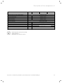
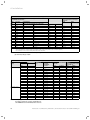
Tab. 4.2 Technical data for auroSTOR solar cylinder
20
Instructions on commissioning, maintenance, and troubleshooting for auroSTOR 0020111119_02
Description of the components 4
Unit
Electrical connections
Immersion heater (according to EN BS 60335)
Length of immersion heater
Two port motorised valve
Cylinder thermostat
Thermal cut-out solar
Material data
Cylinder body material
Cylinder jacket material
Insulation material
Insulation thickness
Corrosion protection
Blowing agent for insulation material
ODP
inch
mm
VIH S GB 210/2 S
VIH S GB 260/2 S
VIH S GB 310/2 S
2.7 kW, 230 V, 50 Hz
14
230/240 V, 50 Hz
230/240 V, 50 Hz
230/240 V, 50 Hz
Stainless steel (1.4521)
Polypropylene
EPS with infrared absorber
50
Stainless steel
Pentane (GWP < 5)
0
Tab. 4.2 Technical data for auroSTOR solar cylinder (continued)
i
The heat up time is based on a flow rate
of 1400 l/h at 80 ºC.
Temperature rise from 15 ºC to 60 ºC.
Instructions on commissioning, maintenance, and troubleshooting for auroSTOR 0020111119_02
21
4 Description of the components
4.3.4
Dimensions
1
2
3
4
5
6
7
9
b
10
c
a
8
k
633
j
i
Ø 554,5
h
g
f
e
d
11
25°
l
45°
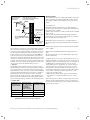
Fig. 4.6 Dimensions of the auroSTOR solar cylinder
Key
1 Hot water draw off
2 Temperature and pressure relief valve connection
3 Secondary return
4 Primary heater flow
5 Primary heating circuit cylinder dry pocket (SP 1)
Unit type
6
7
8
9
10
11
Primary heater return
Electric immersion heater
Solar flow
Solar circuit cylinder dry pocket (SP 2)
Cold mains inlet connection
Solar return
a
b
c
d
e
f
g
h
i
j
k
l
VIH S GB 210/2 S
1625
1593
1341
1158
1052
912
822
802
534
506
259
51
VIH S GB 260/2 S
1875
1843
1591
1346
1102
962
872
852
534
506
259
51
VIH S GB 310/2 S
2185
2153
1901
1578
1377
1237
1147
1127
534
506
259
51
Tab. 4.3 Dimensions
22
Instructions on commissioning, maintenance, and troubleshooting for auroSTOR 0020111119_02
Assembly 5
5
Assembly
5.1
5.2
Transporting the cylinder
Scope of delivery
a
8
7
6
1
5
4
3
> Transport the packaged cylinder to the installation site.
> Only remove the cylinder from its packaging once
it reaches the installation site.
5.3
2
Danger!
Risk of injury due to heavy load!
Heavy load can cause injuries.
> At least two people should lift the cylinder to prevent injuries.
> Use a suitable transportation aid
(sack truck or similar).
Requirements for installation site
Position the domestic hot water cylinder as near as
possible to the heater to prevent unnecessary heat loss.
Place the cylinder in a suitable location in the building,
paying attention to the following:
Fig. 5.1 Scope of delivery
Item
Quantity Component
1
1
Domestic hot water cylinder with insulation
in separate packaging
2
2
Instructions on commissioning, maintenance,
and troubleshooting and operating instructions (packaged with the cylinder)
In separate packaging:
3
1
Safety assembly (pressure reducing valve,
expansion relief valve, connections for pressure-controlled cold water inlet and hot water
expansion vessel)
4
1
Two port motorised valve
5
1
15 mm compression cap for secondary return
6
1
Tundish
7
1
Assembly set for hot water expansion vessel
1
Hot water expansion vessel:
12 l for VIH GB 120/2 S and VIH GB 155/2 S
18 l for VIH GB 180/2 S and VIH GB 210/2 S
25 l for VIH GB 260/2 S and VIH GB 310/2 S
8
– The tundish discharge pipe must be installed with a minimum slope of 1:200 and must end in a safe and visible
place (¬ section 6.7).
– The installation surface must be flat and capable
of bearing the weight of the entire cylinder
(¬ section 5.3).
– The installation site must not be at risk of frost.
If necessary, install a frost protection thermostat.
– The control system for the installed cylinder thermostat
beneath the front plate must be easily accessible to the
operator.
– There must be sufficient space for the assembly, check,
and pressure build-up of the expansion vessel.
– There must be sufficient space for mounting, maintaining and replacing the electric immersion heater.
– The floor must be even.
> Choose a cylinder installation site that allows the potable
water and heating lines to be laid in an appropriate manner.
> To prevent energy losses in accordance with the Heating
Equipment Ordinance, provide all system pipes with thermal insulation.
Table 5.1 Scope of delivery
> Check the scope of delivery for completeness.
> Make sure the cylinder is stored in an upright position in
a dry environment prior to its installation.
Instructions on commissioning, maintenance, and troubleshooting for auroSTOR 0020111119_02
23
6 Installation
6
6.1
Installation
Installation sequence
Install the solar heating system in the following order:
–
–
–
–
–
Solar collectors and solar pump unit
Cylinder
Solar circuit piping
Primary heating circuit piping
Hot water piping, with secondary circulation line if required
– Cold water piping
– Discharge pipes
– Electrical installation
6.2
Installation of solar circuit piping
6.2.1
Piping material in the solar circuit
All Vaillant solar sets are supplied with pipes made from
stainless steel with DN fittings.
b
> Assemble the collectors in accordance with the assembly
instructions supplied with the collector assembly set.
> Install the solar pump unit in accordance with the installation instructions supplied with the solar pump unit.
> For the rest of the installation process, proceed
as described in the sections below.
6.2.2
Caution!
Risk of damage to the system if the
wrong piping material is used in the solar
circuit!
The solar fluid can reach high temperatures
and leaks can occur if the wrong piping
material is used (e.g. PE pipes and Teflon
band).
> You should preferably use copper pipes
in the solar circuit.
> Use brazing solder to solder the piping
in the solar circuit.
> Only use press fittings if the manufacturer has stated that they can be used up
to
a temperature of 200 ºC.
Layout of piping in the solar circuit
The correct choice of pipe diameter is vital to ensure
the optimum efficiency of the solar heating system.
To keep the pressure loss in the solar circuit as low as
possible, the flow velocity in the pipe must not be more
than 1.5 m/s.
At the same time, the flow velocity must be at least
0.4 m/s to transport air bubbles from the collectors
downwards to the air vents (¬ section 6.2.4).
A nominal flow rate of 0.66 l/min is required for the flat
collectors and a nominal flow rate of 0.4 l/min per m2 of
net collector area is required for the vacuum tube collectors in order to achieve optimum heat transfer (¬ table
6.1 and 6.2).
A further decisive factor to ensure that your solar heating system works as well as possible is the correct solar
pump design. It must be possible for the solar pump to
convey more than the nominal flow rate at the specified
operating pressure. The selection of the required pump
speed depends on the installed system. For a reference
value for the selection of a solar pump, see section 7.4.
24
Instructions on commissioning, maintenance, and troubleshooting for auroSTOR 0020111119_02
Installation 6
6.2.3
Realisation of solar circuit piping
a
Danger!
Risk of death from electric shock!
Incorrect installation or a faulty power
cable can result in a supply voltage on the
pipes, which can cause personal injury.
> Attach earthing pipe clamps to the pipes
and connect the earthing pipe clamps to
a potential equalisation bar using 16 mm2
cable.
b
Caution!
Risk of damage to electronics resulting
from lightning strikes!
Without potential equalisation, lightning
can destroy the electronics in the solar
heating system, heating system, or building.
> Earth the solar circuit in accordance with
the requirements of "BS 7671 IEE Wiring
Regulations". Attach earthing pipe
clamps to the solar circuit pipes, for
instance, and connect the earthing pipe
clamps to a potential equalisation bar
using 16 mm2 cable.
> Connect the collectors to an existing building lightning protection system.
b
Caution!
Risk of damage to the collectors due
to excessive pressure.
The safety devices in the solar circuit can
be knocked out of operation if you install a
two port motorised valve in the pipes of the
solar heating system.
> Never install a two port motorised valve
in the pipes of the solar heating system.
Observe the following points to ensure perfect operation
with maximum energy utilisation:
> Ensure that the piping diameter is not too large, since
this could result in low flow velocities in the solar heating system; this makes the system less efficient.
> Design all system components to ensure an even flow
rate with the required nominal flow rate.
> Ensure sufficient heat protection for the pipes so that
not too much heat energy is lost before it reaches the
consumers. For pipes laid outside, choose weather- and
UV-resistant insulation and insulation which is resistant
to the pecking of birds.
> Vent the system completely for commissioning and maintenance, since air in the system significantly impairs its
efficiency.
Instructions on commissioning, maintenance, and troubleshooting for auroSTOR 0020111119_02
25
6 Installation
Nominal flow rate and pipe diameter in the solar circuit
Flat collectors auroTHERM plus VFK 150 H/V,
auroTHERM VFK 145 H/V
Quantity
Qty.
1
2
3
4
5
6
7
8
9
10
11
12
20
24
32
*
**
Nominal flow rate **
Net area
Recommended diameter for
copper piping and a total pipe
length of:
20 m
50 m
Configuration
Row x collector quantity for connection:
in m2
On one side
Opposite sides
l/h
l/min
2,35
1x1
1x1
180
3
15 x 1
4,7
1x2
1x2
180
3
15 x 1
7,05
1x3
1x3
180
3
15 x 1
9,4
1x4
1x4/2x2
180
3
15 x 1
11,75
1x5
1x5
180
3
18 x 1
14,1
3x2*/2x3*
1x6/3x2*/2x3*
212
3,6
18 x 1
16,45
1x7
247
4,2
18 x 1
18,8
2x4*/4x2*
2x4/4x2/1x8
282
4,7
18 x 1
21,15
1x9
318
5,3
22 x 1
23,5
2x5*/5x2*
1 x 10 / 2 x 5 / 5 x 2
353
5,9
22 x 1
25,8
1 x 11
387
6,5
22 x 1
28,2
1 x 12 / 2 x 6 / 3 x 4 / 4 x 3
423
7,1
22 x 1
47
4x5/5x4
705
11,8
22 x 1
56,4
2 x 12 / 4 x 6 / 6 x 4 etc.
846
14,1
28 x 1.5
75,2
4 x 8 etc.
1128
18,8
28 x 1.5
Only with parallel array connection
At least 15 l/m2 h in collector array or 3 l/min. in the solar circuit; in the case of larger systems,
the flow rate in the collector array must be below 30 l/m2 h.
15 x 1
15 x 1
15 x 1
18 x 1
18 x 1
18 x 1
18 x 1
22 x 1
22 x 1
22 x 1
22 x 1
22 x 1
28 x 1.5
28 x 1.5
28 x 1.5
Tab. 6.1 Nominal flow rate in relation to collector quantity,
pipe diameter, and pipe length
Nominal flow rate and pipe diameter in the solar circuit
Parallel collector Tube collectors
arrays
VTK 570/2 VTK 1140/2
1 collector array
2 parallel collector arrays
Qty.
2
2
1
1
1
1
1
2
2
2
2
-
2
2
3
3
4
4
5
5
6
6
7
6
8
8
10
10
12
12
14
Net area
in m2
2
2
4
5
6
7
8
9
10
11
12
13
14
14
16
18
20
22
24
26
28
VTK 1140/2
or 570/2
and 1140/2
in series
2x1
3x1
1x2
1x (1 + 2)
1x3
1 x (1 + 3)
1x4
1 x (1 + 4)
1x5
1 x (1 + 5)
1x6
1 x (1 + 6)
1x7
2 x (1 + 3)
2x4
2 x (1 + 4)
2x5
2 x (1 + 5)
2x6
2 x (1 + 6)
2x7
Recommended nominal Minimum diameter for
flow rate
copper piping and a total
pipe length of:
in l/h
in l/min
20 m
50 m
180
3
12 x 1
15 x 1
180
3
12 x 1
15 x 1
180
3
12 x 1
15 x 1
180
3
12 x 1
15 x 1
180
3
12 x 1
15 x 1
210
3,5
15 x 1
15 x 1
210
3,5
15 x 1
15 x 1
210
3,5
15 x 1
15 x 1
210
3,5
15 x 1
15 x 1
240
4
18 x 1
18 x 1
240
4
18 x 1
18 x 1
240
4
18 x 1
18 x 1
240
4
18 x 1
18 x 1
300
5
18 x 1
18 x 1
300
5
18 x 1
18 x 1
360
6
18 x 1
18 x 1
360
6
18 x 1
18 x 1
420
7
18 x 1
22 x 1
480
8
22 x 1
22 x 1
480
8
22 x 1
22 x 1
480
8
22 x 1
22 x 1
Tab. 6.2 Design of pipe diameter and recommended nominal
flow rate in relation to collector configuration for
auroTHERM exclusive VTK 570/2 tube collectors
26
Instructions on commissioning, maintenance, and troubleshooting for auroSTOR 0020111119_02
Installation 6
6.2.4
Venting the solar circuit
a
Danger!
Risk of burns and scalds resulting from
escaping hot steam!
Hot steam can discharge from automatic
air vents which are not shut off if the system is
in stagnation.
> Use automatic air vents with a
manufacturer's release to at least 150 ºC.
> Shut off the automatic air vents when
operating the system.
b
Caution!
Malfunction due to air vents that are not
shut off!
Vapourous solar fluid can escape from
automatic air vents which are not shut off
whilst the system is in stagnation. The loss
of solar fluid results in functional problems.
> Close all automatic air vents once venting is complete.
b
Caution!
Malfunction due to unsuitable air vents!
Unsuitable air vents can be destroyed in
solar mode.
> Only use Vaillant automatic air vents
with
a manufacturer's release to at least
150 ºC.
Venting via
Solar circuit filling with
Vent opening
for flat collectors
or
Automatic air vent
with stop cock
Automatic
air separator system
Hand pump
Motorised filling pump
(maximum flow rate of
< 10 l/min)
Motorised filling pump
(maximum flow rate of
> 10 l/min)
Absolutely vital
Alternative
Recommended
Not necessary
Recommended
Tab. 6.3 Selection of venting method in accordance
with filling type
Instructions on commissioning, maintenance, and troubleshooting for auroSTOR 0020111119_02
27
6 Installation
Air in the system impairs the efficiency of the solar
heating system considerably. For this reason, there must
be sufficient venting points in every solar circuit.
Automatic air separator system
> Select one of the following venting methods in relation
to the filling type of the solar circuit as per
Tab. 6.3:
– Only for flat collectors: Venting via the vent opening
(¬ Fig. 6.1)
– Venting via an air separator system (¬ Fig. 6.2)
Vent opening (only for flat collectors)
1
2
Fig. 6.1 Plug with vent opening for flat collectors
Key
1 Plug
2 Vent opening
The vent opening enables the venting of the solar circuit
during filling and flushing, i.e. during commissioning or
maintenance.
> For flat collectors, install a plug with a vent opening at
the highest point.
i
Whilst the solar heating system is being operated, the vent opening must be closed to prevent the loss of fluid at times of stagnation.
Fig. 6.2 Automatic air separator system
You can use the Vaillant automatic air separator system
instead of an automatic air vent.
An air separator system vents the solar circuit completely automatically, both during filling and flushing and
continuously whilst the solar heating system is being
operated.
i
You must install an air separator system in
an area where no steam will escape, preferably
in the return line between the solar pump unit
and the solar cylinder.
> Install the Vaillant automatic air separator system in
accordance with the corresponding assembly instructions.
28
Instructions on commissioning, maintenance, and troubleshooting for auroSTOR 0020111119_02
Installation 6
6.3
Pipes for the primary heating circuit
6.4
Make sure that the pipes in the primary heating circuit
between the gas-fired wall-hung boiler and cylinder are
as short as possible. Use copper piping with a minimum
diameter of 22 mm.
A heating pump is installed in all Vaillant gas-fired wallhung boilers (apart from the ecoMAX pro with open ventilation). If you are using the cylinder with another gasfired wall-hung boiler as per GB standards, you may have
to install a suitable heating pump in the primary heating
circuit.
Installing the two port motorised valve
1
Installing hot water pipes
> Connect the hot water piping to the 22 mm hot water
draw off of the cylinder.
> Lay the 22 mm piping up to the first T-piece.
The required diameter of subsequent pipes depends
on the system design.
Connecting up the secondary circulation line
The cylinder has a connection with a 15 mm diameter
for a secondary circulation line.
> Connect a WRAS-approved circulation pump which has a
non-return valve with the secondary return.
> Establish the connection to the secondary circulation
line.
i
i
6.5
If a secondary circulation line is used, an additional expansion vessel may be required in
some circumstances.
If you are not using the secondary return,
this must be properly closed off with the cap
included in delivery.
Hot water thermostat mixer
Fig. 6.3 Two port motorised valve
The two port motorised valve prevents the cylinder from
overheating.
1
AB
A
> Install the two port motorised valve (1) supplied with the
cylinder in the flow line (A ¬ Fig. 3.1) of the gas-fired
wall-hung boiler.
> Note the direction of flow, which is marked with arrows.
i
You can install the 2-way motorised valve vertically or horizontally. If you install the 2-way
motorised valve horizontally, you must install
the valve with the valve head facing upwards
(¬ fig. 6.3).
2
B
Fig. 6.4 Hot water thermostat mixer
Key
1 Thermostat mixer
2 Non Return Valve
A Hot water
B Cold water
AB Mixed water
In a solar heating system, a hot water thermostat mixer
must be installed as scald protection. The hot water
thermostat mixer mixes the hot water from the cylinder
with cold water to produce water with a maximum temperature of between 30 and 60 ºC as required.
The hot water thermostat mixer must be provided by the
customer.
Instructions on commissioning, maintenance, and troubleshooting for auroSTOR 0020111119_02
29
6 Installation
6.5.1
Installing the hot water thermostat mixer
(without secondary circulation line)
6.5.2
Installing the hot water thermostat mixer
(with secondary circulation line)
3
2
2
3
4
230
1
1
7
5
6 5
8
4
6
1
10
Fig. 6.5 Installing the hot water thermostat mixer
(system without secondary circulation line)
Fig. 6.6 Installing the hot water thermostat mixer
(system with secondary circulation line)
Key
1 Non-return valve
2 Hot water thermostat mixer
3 Hot water pipe
4 Cold mains inlet
5 Expansion relief valve
6 Bivalenter solar cylinder
Key
1 Non-return valve
2 Hot water thermostat mixer
3 Solar controller
4 Hot water pipe
5 Secondary circulation line
6 Circulation pump
7 Contact thermostat
8 Expansion relief valve
9 Cold mains inlet
10 Bivalent solar cylinder
> Install a hot water thermostat mixer (2) in the hot water
pipe (3).
9
Where possible, avoid installing a secondary circulation
line, since a secondary circulation line results in higher
energy consumption. If the installation of a secondary
circulation line is required, keep circulation operations to
a minimum by only using circulation mode when
required for demand and temperature reasons.
> Connect the secondary circulation line (5) to the hot
water pipe (4) via a hot water thermostat mixer (2).
6.5.3
Setting the hot water thermostat mixer
a
Danger!
Risk of burns and scalds!
Water at a temperature of more than 60 ºC
can escape from the water draw-off point.
> Set the hot water thermostat mixer to
less than 60 ºC and check the temperature at a hot water draw-off point.
> When commissioning the solar heating system for the
first time, set the hot water thermostat mixer to the
required maximum temperature.
This maximum temperature is observed at the hot water
draw-off points.
30
Instructions on commissioning, maintenance, and troubleshooting for auroSTOR 0020111119_02
Installation 6
6.6
Installation of cold mains inlet
6.6.1
Pressure in cold mains inlet
6.6.2
The efficiency of an unvented cylinder depends on the
available pressure in the cold mains inlet and the flow
rate. To obtain optimum cylinder output, there must be
a suitable cold mains inlet, i.e. the measured static line
pressure must be at least 2.0 bar. A corresponding flow
rate of at least 20-25 l/min must be available.
i
Mounting the safety assembly
b
Caution!
Risk of damage to the cylinder as a
result of excess pressure!
Excess pressure can cause the cylinder
to burst.
> Make sure that there is no stop valve installed between the safety assembly
and the cylinder.
The pressure in the cold mains inlet will be
reduced at times of high consumption. Thus,
measurements should be taken at such times.
The cylinder still works satisfactorily with a pressure
below 2 bar but the flow rate is reduced. If the pressure
is below 1 bar, you should not install an unvented cylinder. Vaillant Ltd. can provide information on alternative
hot water supply systems.
1
7
6
5
80
2
4
Flow rate (l/min)
60
3
40
Fig. 6.8 Safety assembly
20
0
1
2
3
4
Inlet pressure (bar)
5
Fig. 6.7 Maximum flow rate of the cold water assembly based
on the supply pressure
The displayed flow rates apply to installations in which
the cold water supply has a dynamic pressure and flow
rate appropriate for the system.
If the static water pressure is less than 1 bar, contact
Vaillant Ltd.
Key
1 Pressure reducing valve with line strainer
2 Cold water inlet
3 Pressure-controlled cold water inlet
4 Cylinder connection
5 Hot water expansion vessel connection
6 15 mm expansion relief valve connection
7 Expansion relief valve
> During the installation process, position the valves so
that you are able to connect the 15 mm connection (6) of
the expansion relief valve (7) with the tundish. Note the
direction of flow, which is marked on the safety assembly
with arrows.
i
The safety assembly must be installed horizontally with the expansion relief valve facing
upwards (¬ Fig. 6.8) in order to prevent the
build-up of dirt.
b
Caution!
Risk of damage to the cylinder as a
result of excess pressure!
Excess pressure can cause the cylinder to
burst.
> Make sure that the expansion relief valve
outlet is not covered or closed.
Instructions on commissioning, maintenance, and troubleshooting for auroSTOR 0020111119_02
31
6 Installation
> Mount the discharge pipe of the expansion relief valve
with a constant slope to the outside. The discharge pipe
must finish at a safe and visible point where there is no
danger of it freezing up and where it poses no risk of
injury to persons.
> Actuate the expansion relief valve regularly to prevent
calcification.
> Connect the cylinder to the cylinder connection (4).
> For the pipe from the main stop valve of the building to
the cylinder, use copper piping with a diameter of at
least 22 mm to ensure that the cylinder is as efficient as
possible. This is particularly important for installations
with a pressure-controlled cold water inlet (3).
> Mount the safety assembly in the cold mains inlet
on the cylinder.
> If necessary, establish the connection to the cold water
inlet (3) with pressure compensation of the safety
assembly.
> Depending on the fittings used and the type of the drawoff points, it may be necessary to install a backflow preventer in the pressure-controlled cold water inlet.
6.6.4
i
6.7
Installation of discharge pipe
6.7.1
Design of discharge pipe
If you mount the safety assembly above the cylinder, you do not need to drain the cylinder in
order to maintain the safety assembly. Make
sure there is sufficient space for maintenance
and connection of the discharge pipe of the
expansion relief valve.
When the discharge pipes are connected, the expansion
relief valve may not be more than 600 mm away from
the temperature and pressure relief valve (¬ fig. 6.9).
6.6.3
Mounting the expansion vessel
The Vaillant solar cylinder is delivered with an external
expansion vessel (ADG).
Connect this expansion vessel to the installed safety
assembly as follows:
Mounting the drain valve
> Mount a drain valve as low as possible between the cylinder and the safety assembly in the cold mains inlet (10
¬ Fig. 4.1).
The drain valve must be provided by the customer.
We recommend mounting a hose which reaches about
1 m under the base of the cylinder to the outlet of the
drain valve.
6.6.5
Laying the pipes to the tundish
> Connect the temperature and pressure relief valve and
the expansion relief valve to the tundish using
15 mm piping.
> Lay the tundish discharge pipe (¬ section 6.7).
i
a
The tundish discharge pipes must be laid at a
sufficient distance from electrical components in
accordance with valid building regulations.
Danger!
Risk of burns and scalds resulting from
escaping hot water!
In the event of a fault, hot water can escape
suddenly from the discharge pipe of the
expansion relief valve.
> Lay the discharge pipe so that it ends at
an easily visible point inside or outside
the building where escaping hot water
does not pose a risk to persons.
> Screw the expansion vessel directly to the safety assembly via the provided connection (5) or
> Connect the expansion vessel with the safety assembly
via a copper pipe or suitable hose line. Make sure the
expansion vessel is supported sufficiently.
> Use the supplied wall bracket if you want to mount the
expansion vessel to a wall.
i
32
In regions with high water pressure (4 bar or
more), you can also connect the mixer tap for a
bath or shower to the cold water inlet with pressure compensation (3) of the safety assembly.
This ensures that the hot and cold water supply
to the mixer tap have the same pressure. You
should install the cold water supply for all other
connections using a T-piece before the safety
assembly in the cold mains inlet to the cylinder.
Instructions on commissioning, maintenance, and troubleshooting for auroSTOR 0020111119_02
Installation 6
Safety valve
(e.g. Temperature
and pressure
relief valve)
Metal discharge pipe (D1)
from temperature and pressure
relief valve to tundish
Max.
600 m
m
Thundish
At least
300 mm
Discharge point
beneath grille
Fixed grille
Metal discharge pipe (D2)
from tundish with constant
incline
Gully with
siphon
Worked example
The example below is for a G1/2 temperature relief valve
with a discharge pipe (D2) having 4 No. 22 mm elbows
and length of 7 m from the tundish to the point of discharge.
From Table 6.4:
Maximum resistance allowed for a straight length of
22 mm copper discharge pipe (D2) from a G1/2 temperature relief valve is: 9.0 m.
Subtract the resistance for 4 No. 22 mm elbows at 0.8 m
each = 3.2 m
Therefore the maximum permitted length equates to:
5.8 m, which is less than the actual length of 7 m therefore calculate the next largest size.
Maximum resistance allowed for a straight length of
28 mm pipe (D2) from a G1/2 temperature relief valve is:
18 m.
Fig. 6.9 Typical drainage installation
The discharge connections of the temperature and pressure relief valve and the expansion relief valve must be
connected to the supplied tundish via 15 mm copper piping. The tundish should be mounted vertically, as close
to the cylinder as possible and not more than 600 mm
from the connection of the temperature and pressure
relief valve. It must be mounted in the same room as the
cylinder at a sufficient distance from the electrical components. The discharge pipes from the temperature and
pressure relief valve and from the expansion relief valve
can be joined above the tundish using a T-piece
(¬ fig. 4.1).
The discharge pipe from the 22 mm connection of the
tundish must be laid using copper piping with a diameter
of at least 22 mm to a safe and visible discharge point.
There must be a vertical section of pipe at least 300 mm
long beneath the tundish before any bends or elbows in
the pipework. If the total resistance of the discharge
pipe exceeds the values specified in Tab. 6.4 below, you
must increase the diameter of the piping. When installing the discharge piping, you must observe Directive G3
(¬ section 2.2).
Minimum diameter
of discharge pipe
(D2) from tundish
Maximum permissible total resistance, expressed as
straight pipe
length (without
elbows or bends)
Resistance due to
each elbow or bend
22 mm
up to 9 m
0.8 m
28 mm
up to 18 m
1.0 m
35 mm
up to 27 m
1.4 m
Subtract the resistance of 4 No. 28 mm elbows at 1.0 m
each = 4.0 m.
Therefore the maximum permitted length equates to:
14 m.
As the actual length is 7 m, a 28 mm (D2) copper pipe
will be satisfactory.
A suitable place for the end of the discharge pipe is, for
example, beneath a fixed grille above the odour seal in a
gully with a siphon. Low discharge pipes, for example up
to 100 mm above external surfaces such as car and
other parking spaces, grasslands, etc. can be used provided that they are secured by a wire fence or something similar to prevent children from coming into contact with the waste water and provided that the system
is not visible. You must not install any valves or stop
cocks in the discharge pipe.
> Make sure that the discharge pipe from the tundish to
the drain has a constant downward incline of at least
1:200.
The discharge pipe from the pressure relief valve of the
Vaillant gas-fired wall-hung boiler can be connected to
the horizontal discharge pipe of the cylinder behind the
tundish using a T-piece.
Tab. 6.4 Sizing of copper discharge pipe "D2" for G1/2
temperature and pressure relief valve outlet size
Instructions on commissioning, maintenance, and troubleshooting for auroSTOR 0020111119_02
33
6 Installation
6.7.2
High drain
6.8
tundish
At least
300 mm
Electrical installation
e
Danger!
Risk of death from electric shock!
Improperly executed electrical connections
can impair the operational safety of the
unit.
> The electrical installation may only be
performed by a competent person approved
at the time by the Health and Safety Executive.
e
Danger!
Risk of death from electric shock!
Without potential equalisation, life-threatening voltage can reach the piping and
water draw-off points.
> Earth the heating system.
Discharge pipe
Metal funnel
Fig. 6.10 High drain connection
The method illustrated in Fig. 6.10 is allowed provided
that no-one inside or outside the building is endangered
by the discharge point.
Examples of points to consider when deciding whether
a location is suitable for the high drain:
– The possibility (taking into account the effect of the
wind) that a person might be located in the area where
the water escapes, and, if this is the case, whether the
water is sufficiently cooled by that point to pose no danger. Thermal conductivity of the structure's surface, climatic conditions and location and orientation of the
discharge pipe may or may not have an effect on reducing the temperature of the discharge water.
– The position of windows and other openings.
– The probability of prams being parked under the drain.
– The resistance of the surface to hot water.
– The possibility of ice forming if the water is discharged
onto paths.
Wiring should be installed by a qualified competent person in accordance with the building regulations, Part P
of the current IEE regulations, and all other applicable
regulations and directives.
You can use standard commercial cables (H05RR-F 3G1.5
or H05VV-F 3G1.5) for the wiring:
– Cross-section of conductors: 1.5 mm2
– Torque for strain relief: 1.5 Nm
– Maximum length of bus cables: 300 m
230 V supply lines and bus cables must be laid separately above lengths of 10 m.
i
6.8.1
The discharge pipes of the tundish, drain valves
and motorised valves, etc. must be laid at a distance from electrical components.
Options for combining control components
> For the installation, use the connection wiring diagram
specified in Tab. 6.5 for the gas-fired wall-hung boiler
and control components used.
Gas-fired wall-hung boiler used
eBUS-compatible gas-fired wall-hung boiler such as the
Vaillant ecoTEC or non-eBUS-compatible gas-fired wallhung boiler from Vaillant or a third-party manufacturer.
Wiring
Wiring via the Vaillant VR 61/2 mixer module or Vaillant
Control Centre as a system solution which enables Vaillant dual-channel eBUS controllers (low-voltage) to be
used with valves and domestic hot water cylinders in the
traditional 230 V range in the English market. Alternatively, using a standard cabling box.
34
Instructions on commissioning, maintenance, and troubleshooting for auroSTOR 0020111119_02
Installation 6
Solar circuit control system
Solar circuit control via one of the following means:
– The auroMATIC 560/2 differential temperature-controlled control set for solar-aided hot water production
– The VRC weather compensator with VR 68/2.
i
The temperature sensors VR 10 (cylinder sensor)
and VR 11 (collector sensor) are supplied with the
VRS 560/2 solar controller or VR 68/2 solar
module.
Control system of the heating circuits
The heating circuits can be controlled via Vaillant programmable room thermostats or weather compensators
in conjunction with the Vaillant range of eBUS-compatible gas-fired wall-hung boilers. You can also use tested
standard operating elements (see above).
For an overview of the combination options for these
control components, see Tab. 6.5.
i
i
All wiring must be carried out in accordance
with BS 7671: "Requirements for electrical installations" (IEE wiring regulations, current edition).
For the wiring of the solar pump, solar
controller, and solar pump thermal cut-outs on
the cylinder (see connection wiring diagrams 1 to
6, ¬ section 6.8.6), an additional terminal strip
is required.
Hot water reheating control
Hot water primary heating control via the auroMATIC
560/2 differential temperature-controlled control set for
solar-aided hot water production with demand-controlled primary heating for Vaillant gas-fired wall-hung boilers. Alternatively, via a Vaillant dual-circuit eBUS controller or a timer (from a third-party manufacturer).
Gas-fired
wall-hung boiler
Wiring via
Solar circuit
control system
Control system of
the heating circuits
Vaillant ecoTEC,
eBUS-compatible
Vaillant Control
Centre
VRS 560/2
Vaillant dual-channel
eBUS controller
Vaillant ecoTEC,
eBUS-compatible
Vaillant Control
Centre
VRS 560/2
Vaillant dual-channel
eBUS controller
Vaillant ecoTEC,
eBUS-compatible
Vaillant Control
Centre
VRS 560/2
Vaillant dual-channel
eBUS controller
Vaillant ecoTEC,
eBUS-compatible
Vaillant Control
Centre
VRS 560/2
Vaillant dual-channel
eBUS controller
Vaillant ecoTEC,
eBUS-compatible
VR 61/2 and
VR 68/2
VRC with
VR 68/2
Vaillant dual-channel
eBUS controller
Non-eBUS-compatible boiler from a
Standard cabling
VRS 560/2
third-party manufac- box
turer
Solar cylinder primary
heating control system
Vaillant dual-channel
eBUS controller with
Vaillant Control Centre
Vaillant dual-channel
eBUS controller with
Vaillant Control Centre
VRS 560/2 with Vaillant
Control Centre
Hydraulic
plan
S plan
1 ¬ Fig. 6.17
Y plan
2 ¬ Fig. 6.18
S plan
3 ¬ Fig. 6.19
VRS 560/2 with Vaillant
Y plan
Control Centre
Vaillant dual-channel
eBUS controller and
S plan
VR 68/2
Programmable timer and
VRS 560/2
room thermostat
Connection
wiring diagram
S or Y plan
4 ¬ Fig. 6.20
5 ¬ Fig. 6.21
6 ¬ Fig. 6.22
Tab. 6.5 Options for combining control components
Instructions on commissioning, maintenance, and troubleshooting for auroSTOR 0020111119_02
35
6 Installation
6.8.2 Electrical connection of control components
1
7
1
12
13
11
2
3
3
2
6
3
5
4
3
4
2
4
5
1
5
10
Fig. 6.12 Cylinder thermostat and thermal cut-out (TCO)
for primary heating circuit
6
6
9
8
7
Key
1 Cylinder thermostat
2 Cylinder thermostat protective earth terminal
3 Cylinder thermostat terminal 1
4 Primary heating circuit TCO protective earth terminal
5 Primary heating circuit TCO C terminal
6 Primary heating circuit TCO reset button
7 Primary heating circuit thermal cut-out (TCO)
Fig. 6.11 Cylinder temperature control
Key
1 Cover cap for reset button for primary heating circuit TCO
2 Primary heating circuit temperature controller
3 Primary heating circuit cylinder dry pocket (SP 1)
4 Electric immersion heater cover
5 Casing
6 Solar circuit cylinder dry pocket (SP 2)
7 Cover cap for reset button for solar circuit TCO
8 Upper cylinder dry pocket
9 Solar circuit thermal cut-out (TCO)
10 Electric immersion heater
11 Lower cylinder dry pocket
12 Primary heating circuit thermal cut-out
13 Cylinder thermostat
1
2
3
4
5
The cylinder has a suitable thermal cut-out for the primary heating circuit (12) and solar circuit (9) and a cylinder thermostat (13).
i
Before wiring the control components, dismantle
the casing (5) to facilitate work on
the components. When reinstalling the casing,
use the cutouts in the casings for routing the
cables.
Fig. 6.13 Solar circuit thermal cut-out (TCO)
Key
1 Solar circuit thermal cut-out (TCO)
2 Solar circuit TCO reset button
3 Solar circuit TCO terminal C
4 Solar circuit TCO protective earth terminal
5 Solar circuit TCO terminal 2
i
36
You must connect the solar pump’s outer conductor from the solar control via terminals "3"
and "5" of the TCO solar circuit in series circuit
to the solar pump.
Instructions on commissioning, maintenance, and troubleshooting for auroSTOR 0020111119_02
Installation 6
6.8.3
Connecting up the electric immersion heater
The Vaillant auroSTOR VIH S GB 210/2 S,
VIH S GB 260/2 S, and VIH S GB 310/2 S solar cylinders
are fitted with an electric immersion heater at the factory.
a
1
2
3
4
3
2
5
1
Caution!
Corrosion and short circuits may occur
due to incorrect earthing.
If you insert a electric immersion heater
into the cylinder, the external voltage may
build up electrical potential in the water
which may result in the electrochemical
corrosion of the electric immersion heater.
> Ensure that both the hot water and cold
water pipes are connected to the earth
line by means of an earth cable directly
on the cylinder.
> You must also make sure that the electric immersion heater is connected to the
earth line via the earthing terminal.
4
> Mount the cover for the electric immersion heater.
5
i
Fig. 6.14 Electrical connection of electric immersion heater
Only switch the immersion heater on once
the cylinder is completely full.
With the isolating switch, the electric immersion heater
can be switched on if the primary heating device has
malfunctioned.
Key
1 Protective earth terminal (PE)
2 Cable grip
3 Electric immersion heater
4 Neutral conductor terminal (N)
5 Outer conductor terminal (L)
e
Danger!
Risk of death from electric shock!
Without potential equalisation, life-threatening voltage can reach the piping and
water draw-off points.
> Earth the electric immersion heater.
> Remove the front cladding of the casing (5 ¬ fig. 6.11)
from the cylinder.
> Dismantle the casing to facilitate work on the components.
> Dismantle the electric immersion heater cover.
> Install a separate electrical power supply for the electric
immersion heater in accordance with current IEE regulations (BS 7671).
– Use heat-resistant cables (H05BN4-F 1.5 mm2, 3-wire
HOFR-coated) for the cabling of the electric immersion heater.
– Use the cable grip (2) to firmly secure the supply
cable of the immersion heater.
– Connect the electric immersion heater to the power
mains via a double pole isolating switch with a contact
separation of at least 3 mm in both poles.
– Protect the circuit using a 16 A fuse.
Instructions on commissioning, maintenance, and troubleshooting for auroSTOR 0020111119_02
37
6 Installation
6.8.4 Connection of the solar pump
Connection wiring diagrams 1, 2, 3, 4, and 6
(VRS 560/2):
1
> Connect the terminal strip with the terminal Kol 1-P of
the VRS 560/2 (1).
Connection wiring diagram 5 (VR 68/2):
> Connect the terminal strip with the terminal Kol 1-P of
the VR 68/2 (1).
3
6.8.5
3
2
Connecting up the solar yield temperature
sensor
3
4
3
1
2
Fig. 6.15 Connection diagram for solar pump
Key
1 VRS 560/2 or VR 68/2
2 Terminal strip for series circuit to solar pump via TCO solar
circuit
3 Solar pump
4 Solar circuit thermal cut-out (TCO)
Connection wiring diagrams 1, 2, 3, 4, and 6:
> Next to the cylinder, install the VRS 560/2 solar controller (1).
Connection wiring diagram 5:
> Next to the cylinder, install the VR 68/2 solar module (1).
> Dismantle the cover of the VRS 560/2 solar controller or
the VR 68/2 solar module.
> Dismantle the cover of the solar circuit thermal
cut-out (4).
> Connect the solar pump (3) in series with the provided
solar circuit thermal cut-out. To do so, use a protected
terminal strip (2) and 3-core cable provided by the customer.
Fig. 6.16 Solar yield temperature sensor
Key
1 Solar yield temperature sensor
2 Solar return
> Mount the solar yield temperature sensor (1) on the
return line (2) of the solar circuit.
Connection wiring diagrams 1, 2, 3, 4, and 6 (VRS 560/2):
> Connect the solar yield temperature sensor to the yield
("Ertrag") terminal of the VRS 560/2 solar controller.
Connection wiring diagram 5 (VR 68/2):
> Connect the solar yield temperature sensor to the yield
("Ertrag") terminal of the VR 68/2 solar module.
The solar pump and solar circuit thermal cut-out must
be earthed using a protective earth.
> You must carry out a protective earth test.
38
Instructions on commissioning, maintenance, and troubleshooting for auroSTOR 0020111119_02
Installation 6
Instructions on commissioning, maintenance, and troubleshooting for auroSTOR 0020111119_02
39
6 Installation
6.8.6
Installing the control components in accordance
with the connection wiring diagrams
2
Solar pump
N PE
230 V grid
L
KOL 1-P
PE
1
2
+
BUS
Vaillant
dual-channel
eBUS controller
2
BUS
N
L
230 V grid
PE 3A
CYL.
+
DHW
M
Brown
Blue
PE
Vaillant
ecoTEC
CH
Brown
Blue
PE
CH
M
DHW
2 1
Cylinder thermostat
and TCO
PE N on off on PE N on
DHW
PE N L
Vaillant Control Centre
BUS
+ - 2 1
C
NTC
TCO solar circuit
SP2
2
DO NOT
USE
NTC
Cylinder
2
VRS 560
KOL 2-P / ZP
N
L
LEG / Byp
3A
EP
Kol 1
PE
LP/UV 1
PE N L PE N L PE N L PE N L 2 1 PE N L
C1 C2
2
2 1
Kol 1
2 1
SP 1
2 1
SP 2
Solar yield
Yield
2 1
SP 3
2
2 1
Ertrag
2 1
Kol 2
2 1
Connection wiring diagram 1 (S plan hydraulics)
Fig. 6.17 Connection wiring diagram 1
40
Instructions on commissioning, maintenance, and troubleshooting for auroSTOR 0020111119_02
Installation 6
–
–
–
–
eBUS-compatible Vaillant gas-fired wall-hung boiler
Wiring via Vaillant Control Centre
Solar circuit control via VRS 560/2 solar controller
Primary heating circuit control via Vaillant dual-channel
eBUS controller
– Room heating control via Vaillant dual-channel
eBUS controller
– S plan hydraulics
> Next to the solar cylinder, install the Vaillant Control Centre.
> Dismantle the cover of the Vaillant Control Centre.
> Insert a VR 10 temperature sensor into the bottom cylinder dry pocket for SP2 (6 ¬ fig. 6.11).
> Connect this lower cylinder sensor (SP 2) to the terminal
SP 2 of the VRS 560/2.
> Mount the VR 11 collector sensor (Kol 1) in the provided
sensor sleeve on the collector array.
> Connect the VR 11 collector sensor to the terminal Kol 1
of the VRS 560/2.
i
The electrical installation of the eBUS connection is
described in the installation instructions for the Vaillant
dual-channel eBUS controller.
> Install the eBUS connection from the gas-fired wall-hung
boiler to the Vaillant Control Centre.
> Install the eBUS connection from the gas-fired wall-hung
boiler to the Vaillant dual-channel eBUS controller.
> Connect the zone valves for the heating circuit and hot
water circuit in accordance with connection diagram 1 (S
plan hydraulics).
> Connect the gas-fired wall-hung boiler, Vaillant Control
Centre, and VRS 560/2 to the power mains.
> Mount the covers for the Vaillant Control Centre and the
VRS 560/2.
> Adjust the Vaillant dual-channel eBUS controller and the
VRS 560/2 solar controller in accordance with their operating and installation instructions.
> Set the maximum cylinder temperature (MAXT 1) to 75 °C
(factory setting) on the auroMATIC VRS 560/2 solar controller (see operating instructions for the VRS 560/2).
The terminals NTC and CYL. of the Vaillant Control Centre may not be connected at the same
time.
Option 1: Upper cylinder sensor (NTC) to Vaillant Control
Centre:
> Insert a VR 10 temperature sensor into the cylinder dry
pocket for SP1 (3 ¬ fig. 6.11).
> Connect the upper cylinder sensor (NTC) to the
terminal NTC of the Vaillant Control Centre.
Option 2: Cylinder thermostat to Vaillant Control Centre:
> Dismantle the cover of the cylinder thermostat (13 ¬ fig.
6.11).
> Connect the terminals 1 (cylinder thermostat)
(3 ¬ fig. 6.12) and C (primary heating circuit TCO)
(5 ¬ fig. 6.12) to the terminal CYL. of the Vaillant Control
Centre.
> Mount the cover for the cylinder thermostat.
> Mount the casing (5 ¬ fig. 6.11) on the cylinder and use
the cutouts in the casings for routing the cables.
> Mount the front claddings of the casing.
Instructions on commissioning, maintenance, and troubleshooting for auroSTOR 0020111119_02
41
6 Installation
2
Solar pump
N PE
230 V grid
L
KOL 1-P
PE
1
2
+
BUS
Vaillant
dual-channel
eBUS controller
2
+
BUS
N
L
230 V grid
PE 3A
CYL.
Vaillant
ecoTEC
CH
Orange
Grey
Brown or white
Blue
PE
M
DHW
2 1
Cylinder thermostat
and TCO
PE N on off on PE N on
DHW
PE N L
Vaillant Control Centre
BUS
+ - 2 1
C
NTC
TCO solar circuit
SP2
2
DO NOT
USE
NTC
Cylinder
2
VRS 560
KOL 2-P / ZP
N
L
LEG / Byp
3A
EP
Kol 1
PE
LP/UV 1
PE N L PE N L PE N L PE N L 2 1 PE N L
C1 C2
2
2 1
Kol 1
2 1
SP 1
2 1
SP 2
Solar yield
Yield
2 1
SP 3
2
2 1
Ertrag
2 1
Kol 2
2 1
Connection wiring diagram 2 (Y plan hydraulics only
with an eBUS-compatible Vaillant wall-hung boiler.)
Fig. 6.18 Connection wiring diagram 2
42
Instructions on commissioning, maintenance, and troubleshooting for auroSTOR 0020111119_02
Installation 6
–
–
–
–
eBUS-compatible Vaillant gas-fired wall-hung boiler
Wiring via Vaillant Control Centre
Solar circuit control via VRS 560/2 solar controller
Primary heating circuit control via Vaillant dual-channel
eBUS controller
– Room heating control via Vaillant dual-channel
eBUS controller
– Y plan hydraulics
> Next to the solar cylinder, install the Vaillant Control Centre.
> Dismantle the cover of the Vaillant Control Centre.
> Insert a VR 10 temperature sensor into the bottom cylinder dry pocket for SP2 (6 ¬ fig. 6.11).
> Connect this lower cylinder sensor (SP 2) to the terminal
SP 2 of the VRS 560/2.
> Mount the VR 11 collector sensor (Kol 1) in the provided
sensor sleeve on the collector array.
> Connect the VR 11 collector sensor to the terminal Kol 1
of the VRS 560/2.
i
The electrical installation of the eBUS connection is
described in the installation instructions for the Vaillant
dual-channel eBUS controller.
> Install the eBUS connection from the gas-fired wall-hung
boiler to the Vaillant Control Centre.
> Install the eBUS connection from the gas-fired wall-hung
boiler to the Vaillant dual-channel eBUS controller.
> Connect the 3-way valve for the heating circuit and hot
water circuit in accordance with connection diagram 2 (Y
plan hydraulics).
> Connect the gas-fired wall-hung boiler, Vaillant Control
Centre, and VRS 560/2 to the power mains.
> Mount the covers for the Vaillant Control Centre and the
VRS 560/2.
> Adjust the Vaillant dual-channel eBUS controller and the
VRS 560/2 solar controller in accordance with their operating and installation instructions.
> Set the maximum cylinder temperature (MAXT 1) to 75 °C
(factory setting) on the auroMATIC VRS 560/2 solar controller (see operating instructions for the VRS 560/2).
The terminals NTC and CYL. of the Vaillant Control Centre may not be connected at the same
time.
Option 1: Upper cylinder sensor (NTC) to Vaillant Control
Centre:
> Insert a VR 10 temperature sensor into the cylinder dry
pocket for SP1 (3 ¬ fig. 6.11).
> Connect the upper cylinder sensor (NTC) to the terminal
NTC of the Vaillant Control Centre.
Option 2: Cylinder thermostat to Vaillant Control Centre:
> Dismantle the cover of the cylinder thermostat (13 ¬ fig.
6.11).
> Connect the terminals 1 (cylinder thermostat)
(3 ¬ fig. 6.12) and C (primary heating circuit TCO)
(5 ¬ fig. 6.12) to the terminal CYL. of the Vaillant Control
Centre.
> Mount the cover for the cylinder thermostat.
> Mount the casing (5 ¬ fig. 6.11) on the cylinder and use
the cutouts in the casings for routing the cables.
> Mount the front claddings of the casing.
Instructions on commissioning, maintenance, and troubleshooting for auroSTOR 0020111119_02
43
6 Installation
2 1
2
Kol 1
2
N PE
Solar pump
2
2 1
L
PE
1
+
BUS
Vaillant
dual-channel
eBUS controller
2
+
N
L
230 V grid
PE 3A
CYL.
BUS
Brown
Blue
PE
Vaillant
ecoTEC
CH
DHW
M
DHW
Brown
Blue
PE
CH
M
DHW
PE N L
Vaillant Control Centre
BUS
PE N on off on PE N on
NTC
+ - 2 1
DO NOT
USE
SP1
SP2
Cylinder
230 V grid
2
KOL 1-P
TCO solar circuit
KOL 2-P / ZP
N
L
LEG / Byp
3A
EP
Kol 1
PE
LP/UV 1
PE N L PE N L PE N L PE N L 2 1 PE N L
C1 C2
VRS 560
2
SP 1
2 1
SP 2
Solar yield
Yield
2 1
SP 3
2
2 1
Ertrag
2 1
Kol 2
2 1
Connection wiring diagram 3 (S plan hydraulics)
Fig. 6.19 Connection wiring diagram 3
44
Instructions on commissioning, maintenance, and troubleshooting for auroSTOR 0020111119_02
Installation 6
–
–
–
–
eBUS-compatible Vaillant gas-fired wall-hung boiler
Wiring via Vaillant Control Centre
Solar circuit control via VRS 560/2 solar controller
Primary heating circuit control via VRS 560/2 solar controller
– Room heating control via Vaillant dual-channel
eBUS controller
– S plan hydraulics
> Next to the solar cylinder, install the Vaillant Control Centre.
> Dismantle the cover of the Vaillant Control Centre.
> Insert a VR 10 temperature sensor into the cylinder dry
pocket for SP2 (6 ¬ fig. 6.11).
> Connect this lower cylinder sensor (SP 2) to the terminal
SP 2 of the VRS 560/2.
> Insert a VR 10 temperature sensor into the bottom cylinder dry pocket for SP1 (3 ¬ fig. 6.11).
> Connect this upper cylinder sensor (SP 1) to the terminal
SP 1 of the VRS 560/2.
> Mount the VR 11 collector sensor (Kol 1) in the provided
sensor sleeve on the collector array.
> Connect the VR 11 collector sensor (Kol 1) to the terminal
Kol 1 of the VRS 560/2.
> Connect the terminal EP of the VRS 560/2 with the terminal CYL. of the Vaillant Control Centre.
i
The electrical installation of the eBUS connection is
described in the installation instructions for the Vaillant
dual-channel eBUS controller.
> Install the eBUS connection from the gas-fired wall-hung
boiler to the Vaillant Control Centre.
> Install the eBUS connection from the gas-fired wall-hung
boiler to the Vaillant dual-channel eBUS controller.
> Connect the zone valves for the heating circuit and hot
water circuit in accordance with connection diagram 3 (S
plan hydraulics).
> Connect the gas-fired wall-hung boiler, Vaillant Control
Centre, and VRS 560/2 to the power mains.
> Mount the covers for the Vaillant Control Centre and the
VRS 560/2.
> Adjust the Vaillant dual-channel eBUS controller and the
VRS 560/2 solar controller in accordance with their operating and installation instructions.
> Set the maximum cylinder temperature (MAXT 1) to 75 °C
(factory setting) on the auroMATIC VRS 560/2 solar controller (see operating instructions for the VRS 560/2).
The terminals NTC and CYL. of the Vaillant Control Centre may not be connected at the same
time.
> Mount the casing (5 ¬ fig. 6.11) on the cylinder and use
the cutouts in the casings for routing the cables.
> Mount the front claddings of the casing.
Instructions on commissioning, maintenance, and troubleshooting for auroSTOR 0020111119_02
45
6 Installation
2 1
2
Kol 1
2
N PE
Solar pump
2
2 1
L
PE
1
+
BUS
Vaillant
dual-channel
eBUS controller
2
+
N
L
230 V grid
PE 3A
CYL.
BUS
CH
Orange
Grey
Brown or white
Blue
PE
Vaillant
ecoTEC
DHW
M
DHW
PE N L
Vaillant Control Centre
BUS
PE N on off on PE N on
NTC
+ - 2 1
DO NOT
USE
SP1
SP2
Cylinder
230 V grid
2
KOL 1-P
TCO solar circuit
KOL 2-P / ZP
N
L
LEG / Byp
3A
EP
Kol 1
PE
LP/UV 1
PE N L PE N L PE N L PE N L 2 1 PE N L
C1 C2
VRS 560
2
SP 1
2 1
SP 2
Solar yield
Yield
2 1
SP 3
2
2 1
Ertrag
2 1
Kol 2
2 1
Connection wiring diagram 4 (Y plan hydraulics)
Fig. 6.20 Connection wiring diagram 4
46
Instructions on commissioning, maintenance, and troubleshooting for auroSTOR 0020111119_02
Installation 6
–
–
–
–
eBUS-compatible Vaillant gas-fired wall-hung boiler
Wiring via Vaillant Control Centre
Solar circuit control via VRS 560/2 solar controller
Primary heating circuit control via VRS 560/2 solar controller
– Room heating control via Vaillant dual-channel
eBUS controller
– Y plan hydraulics
> Next to the solar cylinder, install the Vaillant Control Centre.
> Dismantle the cover of the Vaillant Control Centre.
> Insert a VR 10 temperature sensor into the cylinder dry
pocket for SP2 (6 ¬ fig. 6.11).
> Connect this lower cylinder sensor (SP 2) to the terminal
SP 2 of the VRS 560/2.
> Insert a VR 10 temperature sensor into the bottom cylinder dry pocket for SP1 (3 ¬ fig. 6.11).
> Connect this upper cylinder sensor (SP 1) to the terminal
SP 1 of the VRS 560/2.
> Mount the VR 11 collector sensor (Kol 1) in the provided
sensor sleeve on the collector array.
> Connect the VR 11 collector sensor (Kol 1) to the terminal
Kol 1 of the VRS 560/2.
> Connect the terminal EP of the VRS 560/2 with the terminal CYL. of the Vaillant Control Centre.
i
The electrical installation of the eBUS connection is
described in the installation instructions for the Vaillant
dual-channel eBUS controller.
> Install the eBUS connection from the gas-fired wall-hung
boiler to the Vaillant Control Centre.
> Install the eBUS connection from the gas-fired wall-hung
boiler to the Vaillant dual-channel eBUS controller.
> Connect the 3-way valve for the heating circuit and hot
water circuit in accordance with connection diagram 4 (Y
plan hydraulics).
> Connect the gas-fired wall-hung boiler, Vaillant Control
Centre, and VRS 560/2 to the power mains.
> Mount the covers for the Vaillant Control Centre and the
VRS 560/2.
> Adjust the Vaillant dual-channel eBUS controller and the
VRS 560/2 solar controller in accordance with their operating and installation instructions.
> Set the maximum cylinder temperature (MAXT 1) to 75 °C
(factory setting) on the auroMATIC VRS 560/2 solar controller (see operating instructions for the VRS 560/2).
The terminals NTC and CYL. of the Vaillant Control Centre may not be connected at the same
time.
> Mount the casing (5 ¬ fig. 6.11) on the cylinder and use
the cutouts in the casings for routing the cables.
> Mount the front claddings of the casing.
Instructions on commissioning, maintenance, and troubleshooting for auroSTOR 0020111119_02
47
6 Installation
L
N PE
2 1
SP2
SP1
PE
1
2
+
VR 81
BUS
+
BUS
+
BUS
Vaillant
dual-channel
eBUS controller
HZ2
M
HZ1
M
Brown
Blue
PE
Vaillant
ecoTEC
230 V grid
2
TCO solar circuit
N
L
Cylinder
VR 61/2
ZP / LP
Brown
Blue
PE
HW
M
HK1 / P
N
L
HK2
Brown
Blue
PE
PE 3A
HK2 / P
+ - 2 1
BUS
PE N L PE N L PE N L PE N on off PE N L
VF2
Solar pump
2
2
230 V grid
Kol 1
3A
MA
PE
KOL 1-P
PE N L PE N L PE N L PE N L
LEG-P
VR 68/2
2
2 1
Kol 1
BUS
Solar yield
Yield
2
SP 1
2 1
SP 2
2
2 1
Ertrag
2 1
TD 1
2 1
TD 2
2 1
Connection wiring diagram 5 (S plan hydraulics)
Fig. 6.21 Connection wiring diagram 5
48
Instructions on commissioning, maintenance, and troubleshooting for auroSTOR 0020111119_02
Installation 6
– eBUS-compatible Vaillant gas-fired wall-hung boiler
– Wiring via VR 68/2 solar module and VR 61/2 mixer
module
– Control of the solar circuit via a VRC weather compensator and the VR 68/2 solar module
– Control of the primary heating circuit via a VRC controller
– Control of the room heating via a VRC controller
– S plan hydraulics with VR 81 for 2nd zone
> Next to the solar cylinder, install the VR 61/2 mixer
module.
> Install a VRC weather compensator next to the solar
cylinder.
> Dismantle the covers of the VR 61/2 and the VRC controller.
> Insert a VR 10 temperature sensor into the cylinder dry
pocket for SP2 (6 ¬ fig. 6.11).
> Connect this lower cylinder sensor (SP 2) to the terminal
SP 2 of the VR 68/2.
> Insert a VR 10 temperature sensor into the bottom cylinder dry pocket for SP1 (3 ¬ fig. 6.11).
> Connect this upper cylinder sensor (SP 1) to the terminal
SP 1 of the VR 68/2.
> Mount the VR 11 collector sensor (Kol 1) in the provided
sensor sleeve on the collector array.
> Connect the VR 11 collector sensor (Kol 1) to the terminal
Kol 1 of the VR 68/2.
The electrical installation of the eBUS connection is
described in the installation instructions for the Vaillant
dual-channel eBUS controller.
> Install the eBUS connection from the gas-fired wall-hung
boiler to the VR 61/2.
> Install the eBUS connection from the gas-fired wall-hung
boiler to the VR 68/2.
> Install the eBUS connection from the gas-fired wall-hung
boiler to the VRC controller.
> Optional: Install the eBUS connection from the gas-fired
wall-hung boiler to the VR 81.
> Connect the zone valves for the heating circuit and hot
water circuit in accordance with connection diagram 5 (S
plan hydraulics).
> Connect the gas-fired wall-hung boiler, VR 61/2, and
VR 68/2 to the power mains.
> Mount the covers of the VR 61/2, the VR 68/2 and the
VRC controller.
> Adjust the Vaillant dual-channel eBUS controller in
accordance with its operating and installation instructions.
> Set the maximum cylinder temperature (MAXT 1) to 75 °C
(factory setting) on the VRC weather compensator (see
operating instructions for the VR 68/2).
> Mount the casing (5 ¬ fig. 6.11) on the cylinder and use
the cutouts in the casings for routing the cables.
> Mount the front claddings of the casing.
Instructions on commissioning, maintenance, and troubleshooting for auroSTOR 0020111119_02
49
6 Installation
2 1
2
Kol 1
2
2
SP 1
KOL 1-P
2 1
SP1
SP2
PE
1
2
Cylinder
TCO solar circuit
PE
N
L
230 V grid
Solar pump
KOL 2-P / ZP
N PE
LEG / Byp
L
EP
Kol 1
3A
LP/UV 1
PE N L PE N L PE N L PE N L 2 1 PE N L
C1 C2
VRS 560
Solar yield
Yield
2 1
SP 2
2 1
SP 3
2
2 1
Ertrag
2 1
Kol 2
2 1
Connection wiring diagram 6 (S plan or Y plan
hydraulics)
PE
C
PE
2 1
Cylinder thermostat
and TCO
Standard cabling box
S-plan or Y-plan
Fig. 6.22 Connection wiring diagram 6
50
Instructions on commissioning, maintenance, and troubleshooting for auroSTOR 0020111119_02
Installation 6
–
–
–
–
Third-party boiler, non-eBUS-compatible
Wiring via standard cabling box
Solar circuit control via VRS 560/2 solar controller
Primary heating circuit control via VRS 560/2 solar controller
– Room heating control via programmable timer and room
thermostat
– S or Y plan hydraulics
> Install a bridge between the protective earth terminal
(2 ¬ fig. 6.12) of the cylinder thermostat and the protective earth terminal (4 ¬ fig. 6.12) of the primary heating
circuit TCO.
> Mount the cover for the cylinder thermostat.
> Mount the casing (5 ¬ fig. 6.11) on the cylinder and use
the cutouts in the casings for routing the cables.
> Mount the front claddings of the casing.
> Next to the solar cylinder, install a standard cabling box.
> Dismantle the cover for the standard cabling box.
> Dismantle the cover of the cylinder thermostat (13 ¬ fig.
6.11).
> Insert a VR 10 temperature sensor into the cylinder dry
pocket for SP2 (6 ¬ fig. 6.11).
> Connect this lower cylinder sensor (SP 2) to the terminal
SP 2 of the VRS 560/2.
> Insert a VR 10 temperature sensor into the cylinder dry
pocket for SP1 (3 ¬ fig. 6.11).
> Connect this upper cylinder sensor (SP 1) to the terminal
SP 1 of the VRS 560/2.
> Mount the VR 11 collector sensor (Kol 1) in the provided
sensor sleeve on the collector array.
> Connect the VR 11 collector sensor (Kol 1) to the terminal
Kol 1 of the VRS 560/2.
For S plan hydraulics:
> Install standard S plan wiring between the boiler,
two port valves, terminal C of the cylinder thermostat,
and the standard cabling box.
For Y plan hydraulics:
> Install standard Y plan wiring between the boiler, 3-way
zone valve, terminal C of the cylinder thermostat, and
the standard cabling box.
> In the VRS 560/2 solar controller, install a bridge from
terminal 230V~, connection L to terminal EP, connection 2.
Connect the VRS 560/2 and the cylinder thermostat
using a 2-core cable (phase conductor and protective
earth):
> Connect the connection 1 of the terminal EP of the VRS
560/2 with the terminal 1 (3 ¬ fig. 6.12) of the cylinder
thermostat.
> Connect the protective earth connection of the VRS 560
with the protective earth terminal (2 ¬ fig. 6.12) of the
cylinder thermostat.
1
C
2
Fig. 6.23 Connections of the cylinder thermostat and the
thermal cut-out
> Connect the boiler, VRS 560/2, and standard cabling box
to the power mains.
> Mount the covers for the VRS 560/2 and the standard
cabling box.
> Adjust the Vaillant VRS 560/2 solar controller in
accordance with its operating and installation instructions.
> Set the maximum cylinder temperature (MAXT 1) to 75 °C
(factory setting) on the auroMATIC VRS 560/2 solar controller (see operating instructions for the VRS 560/2).
i
The switching signal for the primary heating of
the hot water is forwarded to the S plan/Y plan
wiring via terminal EP of the VRS 560/2, the cylinder thermostat, and the primary heating circuit TCO.
Connect the standard cabling box with the thermal cutout (TCO) for the primary heating circuit using a 2-core
cable (phase conductor and protective earth):
> Connect the standard cabling box with the terminal C
(5 ¬ fig. 6.12) of the primary heating circuit TCO.
> Connect the protective earth connection of the standard
cabling box with the protective earth terminal (4 ¬ fig.
6.12) of the primary heating circuit TCO.
Instructions on commissioning, maintenance, and troubleshooting for auroSTOR 0020111119_02
51
7 Commissioning
7
Commissioning
You must adhere to the following procedure for the
commissioning of the total system:
>
>
>
>
>
>
>
4
Check for leak-tightness.
Flush the solar circuit with solar fluid.
Fill the solar circuit with solar fluid.
Set the solar pump.
Set the flow rate limiter.
Check the controller.
Set the hot water thermostat mixer.
i
6a 6b
2
7.1
5
For the pressure test, first fill the solar circuit with
Vaillant solar fluid (ready mixed).
A self-priming filling pump with a pressure of 2 to 3 bar
is required to fill the solar circuit.
1
14
13
16
12
20
17
21
11
9
19
10
Fig. 7.1 Checking, flushing, and filling the solar circuit
Key
1 Combined filling and draining tap
2 6 bar expansion relief valve
4 Air vent
5 Solar protection vessel
6a Flow line thermometer
6b Return line thermometer
7 Pressure gauge
8 Flow line ball valve with non-return valve
9 Filter
10 Solar fluid container
11 Combined filling and draining tap
12 Flow rate limiter
13 Solar pump
14 Return line non-return valve
15 3-way ball valve with non-return valve
16 Combined filling and draining tap
17 Return hose
19 Filling pump
21 Vaillant automatic air separator system
52
Checking leak-tightness
7
15
8
Only use Vaillant solar fluid for pressure tests,
flushing, and filling.
> Connect the pressure hose of the filling pump (19) to the
upper combined filling and draining tap (1) of the solar
circuit.
> Connect the return hose (17) to the lower combined filling and draining tap (16) of the solar circuit.
> Close the 3-way ball valve (15).
> Open the air vent (4).
> Switch the filling pump on.
The solar fluid now flows into the solar circuit.
> Place enough solar fluid into the container (10) to ensure
that the filling pump cannot run dry.
> Allow the system to pump the solar fluid (ready mixed)
out of the container (10) via the combined filling and
draining tap (1) until solar fluid runs back out of the
return hose (17) and into the container (10).
> Close the combined filling and draining tap (16).
> Let the pressure build to around 4.5 bar.
> Close the combined filling and draining tap (1) and immediately switch the filling pump off.
> Carry out a visual inspection of the pipes and connections.
> Rectify any leaks and then check again.
i
Only flush the solar circuit following
a successful pressure test.
Instructions on commissioning, maintenance, and troubleshooting for auroSTOR 0020111119_02
Commissioning 7
7.2
Flushing the solar circuit with solar fluid
Flushing is performed from the solar pump unit to the
cylinder via the collector.
> Connect the pressure hose of the filling pump (19) to the
upper combined filling and draining tap (1) of the solar
circuit.
> Connect the return hose (17) to the lower combined filling and draining tap (16) of the solar circuit.
> Close the 3-way ball valve (15).
> Open the air vent (4).
> Switch the filling pump on.
> Place enough solar fluid into the container (10) to ensure
that the filling pump cannot run dry.
> Allow the system to pump the solar fluid out of the container via the combined filling and draining tap (1) until
solar fluid runs back out of the return hose (17) and into
the container (10).
> Allow the solar fluid to circulate in the circuit for at least
15 minutes to flush the solar circuit and filter the solar
fluid.
7.3
The vent operation was successful if the fluid in
the solar fluid container is clear and no more bubbles
rise to the surface.
> Use the screw cap opening on the solar fluid container to
carry out the visual check.
> Set the 3-way ball valve (15) on the solar pump unit to
45° (non-return valve out of operation).
> Allow the filling pump to run for a further 5 minutes to
vent the pipeline between the combined filling and draining taps (1) and (16).
> After 5 minutes, close the 3-way ball valve (15) again
(horizontal position).
> Close the combined filling and draining taps (1) and (16)
and then immediately switch off the filling pump.
> Place the 3-way ball valve (15) into the vertical position
again (flow and non-return valve working).
> Remove the pressure hose and return hose of the solar
circuit combined filling and draining taps.
The system is now filled and vented.
Filling the solar circuit with solar fluid
> First, carry out a pressure test and flush the system with
Vaillant solar fluid (ready mixed).
> Connect the pressure hose of the filling pump (19) to the
upper combined filling and draining tap (1) of the solar
circuit.
> Connect the return hose (17) to the lower combined filling and draining tap (16) of the solar circuit.
> Completely open the combined filling and draining taps
(1) and (16) on the solar pump unit to ensure a maximum
flow rate.
> Open the ball valve (8) on the solar pump unit.
> Close the 3-way ball valve (15) on the solar pump unit.
> Switch the filling pump on.
> Place enough solar fluid into the container (10) to ensure
that the filling pump cannot run dry.
> Check to see whether the solar fluid is running out of the
return hose (17) and back into the container (10).
> Allow the filling pump to run for at least 15 minutes to
sufficiently vent the solar circuit.
Instructions on commissioning, maintenance, and troubleshooting for auroSTOR 0020111119_02
53
7 Commissioning
7.4
Setting the flow rate in the solar circuit
In addition to factors such as the temperature, pipe
diameter, number of collectors and so on, the flow rate
is important for ensuring optimum heat transfer. A flow
rate above the nominal flow rate is not as unfavourable
as a flow rate below the nominal flow rate.
i
Never allow the flow rate to fall below the nominal flow rate. Doing so can cause the efficiency
of the collectors to drop significantly, resulting
in a solar yield of up to 10% less and unnecessarily high power consumption by the solar
pump.
The solar pump unit has a three-stage solar pump and a
flow rate limiter to enable it to optimally modify the flow
rate in line with the collector performance.
– In conjunction with central air vents, the flow rate in the
solar circuit should be at least 3 l/min so that the residual air in the system is pulled along with the solar fluid
and conveyed to the air vents.
– You must maintain a flow rate of at least
0.25 l/m2 min in the collector array.
– In the case of small systems with a net area of up to
10 m2, a flow rate of 0.50 to
0.67 l/m2 min is recommended in the collector array.
– In the case of larger systems, the flow rate in the collector array must be lower than 0.50 l/m2 min.
1
0,5
2
4
3
6
5
1
0,5
3
2
4
L/min
5
6
L/min
For a suitable nominal flow rate for the collectors, pipe
diameter, and pipe length used, see Tab. 6.1 and 6.2.
> Determine the nominal flow rate to be set from Tab.
6.1/6.2.
> Completely open the flow rate limiter with the control
valve (1).
> Allow the solar pump to run on the lowest pump speed.
> Check the flow rate on the indicator (2) of the flow rate
limiter.
> Choose a pump speed that sets the flow rate to equal to
or more than the nominal flow rate.
– If the actual flow rate is lower than the nominal flow
rate, switch to the next higher pump speed.
– If the nominal flow rate cannot be reached even at the
highest pump speed, check to see whether it is possible to connect less collectors in series and to switch to
a combination of series and parallel connections.
Check out other ways of reducing the pressure loss.
Observe here the Vaillant solar planning information.
> Use the control valve (1) of the flow rate limiter to set
the flow rate so that it is slightly higher than the nominal
flow rate.
If you are using the auroMATIC 620 controller, you can
use the set flow rate to calculate the yield.
> Enter the set flow rate on the controller; the controller
then calculates the yield.
For more information, see the operating and installation
instructions for the controller.
i
Set the flow rate in the solar circuit as specified
in ¬ tab. 6.1 or ¬ tab. 6.2.
1
1,1l/min
2
Fig. 7.2 Flow rate limiter
54
Instructions on commissioning, maintenance, and troubleshooting for auroSTOR 0020111119_02
Commissioning 7
7.5
Flushing the primary heating circuit
Detailed recommendations for the water circuit can be
found in BS 6798 and BS 5449: Part 1 (for central heating systems with both small and the smallest pipe
width).
Pipes which do not form part of the usable heating surface must be insulated in order to prevent heat losses
and possible freezing. Pipe insulation is particularly
important if you are installing pipes under the roof or
in open areas under the floor.
Discharge valves must be mounted in easily accessible
locations, so that the entire system, including the boiler
and hot water system, can be discharged. Discharge
valves must have a nominal size of 1/2 inch BSP and
comply with BS 2879.
Copper pipes which comply with BS 2871: Part 1 for
water-carrying pipes must be used. All soldered connections in the private hot water pipe system must be made
with lead-free soldering material.
b
Caution!
Risk of material damage as a result
of deposits in the unit or system!
Cleaning agents can result in deposits and
follow-on damages.
> Use a suitable cleaning agent in
accordance with this instruction manual.
> Never leave cleaning agents in the system for longer than 24 hours.
> Completely remove the cleaning agents
from the system by flushing it thoroughly.
All cleaning must be performed before installing the new
boiler and must comply with BS 7593. Information on
the use of cleaning agents for the system can be
obtained from Sentinel, Betz Dearborn Ltd. Widnes,
Cheshire, WA8 8UD. Tel: 0151 420 9595, or Fernox, Alpha
Fry Technologies, Tandem House, Marlow Way, Croydon,
CR0 4XS. Tel: 0870 8700362.
7.6
Water treatment
b
Caution!
The use of unsuitable heating water can
cause aluminium corrosion resulting in
leaks!
In contrast to steel, grey cast iron, and copper, for example, aluminium reacts with
alkaline heating water (pH value > 8.5) to
produce substantial corrosion.
> When using aluminium, make sure that
the pH value of the heating water is between 6.5 and a maximum of 8.5.
b
Caution!
Risk of material damage as a result of
enriching the heating water with unsuitable frost or corrosion protection agents!
Frost and corrosion protection agents can
cause changes to the seals, noises during
heating mode and possibly subsequent damage.
> Do not use any unsuitable frost and corrosion protection agents.
Mixing additives with the heating water can result in
material damage. However no incompatibility with Vaillant units has been detected with proper use of the following products over a long period.
> When using additives, follow the manufacturer's instructions without exception.
Vaillant does not accept any liability relating to the compatibility or efficiency of any additives throughout the
heating system
Additives for cleaning measures
(subsequent flushing required)
– Fernox F3
– Sentinel X 300
– Sentinel X 400
Additives intended to remain permanently
in the system
–
–
–
–
Fernox F1
Fernox F2
Sentinel X 100
Sentinel X 200
Additives for frost protection intended to remain
permanently in the system
– Fernox Antifreeze Alphi 11
– Sentinel X 500
Instructions on commissioning, maintenance, and troubleshooting for auroSTOR 0020111119_02
55
7 Commissioning
> Inform the operator of the necessary measures if you
have used these additives.
> Inform the operator about the required measures for
frost protection.
> Observe all valid national and technical regulations when
treating the filling and supplementary water.
7.7
Filling the cylinder
b
Caution!
Risk of material damage due to unsuitable water!
Unsuitable water can lead to deposits and
corrosion damage in the cylinder and in the
hot water circuit.
> Use only potable water with a chloride
content of below 250 mg/l in the hot
water circuit.
i
Use the draw-off points to vent the cylinder and
water pipes. Do not use the combined temperature/pressure relief valve of the cylinder or the
pressure relief valve of the cold water safety
assembly for venting, since foreign bodies can
contaminate or damage the valves.
Provided the national regulations and technical standards do not stipulate more stringent requirements, the
following applies:
> You must treat the heating water in the following cases:
– If the entire filling and supplementary water quantity
during the operating life of the system exceeds three
times the nominal volume of the heating system
or
– If the limit values shown in the tables are not observed.
Total heating
output
Overall hardness at smallest boiler heating
surface2)
20 l/kW
> 20 l/kW
< 50 l/kW
> 50 l/kW
kW
mol/m3
mol/m3
mol/m3
< 50
No requirement
2
or < 31)
0,02
> 50 to £ 200
2
1,5
0,02
> 200 to £ 600
1,5
0,02
0,02
> 600
0,02
0,02
0,02
1) For systems with circulation water heaters and for systems
with electric heating elements
2) Of specific system volume (nominal content in litres/heating
output; in the case of multi-boiler systems, the smallest single
heating output is to be used).
These values only apply up to 3 times the system volume for
filling and supplementary water. Once this triple system volume is exceeded, the water will have to be treated exactly the
same as in case of exceeding the limit values given in this table
(softening, desalination, hardness stabilisation and desludging).
> Make sure that the drain valve is closed.
> Open all of the draw-off points in the cold and hot water
pipes.
> Open the water supply inlet to the cylinder and allow the
water to run until bubble-free water runs from all of the
draw-off points and the air is removed from the system.
> Close all of the draw-off points.
> Check the system for leaks.
In particular, check the installed electric immersion heater for leaks.
> Open two hot water draw-off points, one at the lowest
point and one at the highest point of the pipe system,
and allow water to run for at least 5 minutes.
> Close both of the hot water draw-off points.
Table 7.3 Guidelines for the heating water: Water hardness
Heating water characUnit
teristics
Electrical conductivity
mS/cm
at 25 ºC
Low-salt
Saline
< 100
100 - 1500
Appearance
Free from sedimentary materials
pH value at 25 ºC
8,2 - 10,0
8,2 - 10,0
< 0.1
< 0.02
Oxygen
mg/l
Table 7.4 Guidelines for the heating water: Salt content
56
Instructions on commissioning, maintenance, and troubleshooting for auroSTOR 0020111119_02
Commissioning 7
7.8
Filling the central heating system
The system can be filled using the built-in filling loop
(ecoTEC plus combi boiler only) or via a separate filling
connection that is fitted at an easily accessible location
in the heating circuit. The filling loop must be removed
once filling is complete. If a temporary connection is not
possible due to legal regulations, a closed system filling
pump with a buffer tank must be used.
The heating system is not automatically supplied from
the hot water side of the central heating. Alternative
procedures for filling closed systems can be found in
BS 5449.
i
3
2
3
4
2
5
1
1
Do not use the pressure relief valve of the gasfired wall-hung boiler for venting.
Fig. 7.4 Setting thermostats
1
Fig. 7.3 Two port motorised valve
> Place the lever (1) on the two port motorised valve
to "MAN OPEN" and lock it into this position.
> Flush the entire primary central heating system including
the primary heating circuit with cold and hot water.
> Flush, fill, and vent the central heating system in
accordance with the installation instructions of the gasfired wall-hung boiler.
> Release the lever on the two port motorised valve
by placing it in the "AUTO" position.
> Remove the upper front cladding (1) from the cylinder.
> Dismantle the electric immersion heater cover.
> Set the cylinder thermostat (3) and the electric immersion heater thermostat (2) to a maximum of 60 °C for
commissioning and to achieve maximum energy efficiency.
> Commission the gas-fired wall-hung boiler (¬ section
7.9) until the cylinder reaches the operating temperature
and all radiators in the system are hot.
> Then drain the entire central heating system again to
remove any residue from the pipes.
> Fill and vent the entire central heating system again as
described in the installation instructions for the gas-fired
wall-hung boiler.
Instructions on commissioning, maintenance, and troubleshooting for auroSTOR 0020111119_02
57
7 Commissioning
7.9
Commissioning the gas-fired wall-hung boiler
> Make sure that the control device and thermostats are
set so that heating is required.
> Carry out the commissioning and testing measures for
the gas-fired wall-hung boiler in accordance with the installation instructions.
> Check whether the gas-fired wall-hung boiler starts operating and the water in the cylinder and radiators heats
up in accordance with the hot water and room
thermostat settings.
> After completing the commissioning measures, set the
hot water temperature on the controller (e.g. auroMATIC
560/2 solar controller) to a maximum of 60 °C to achieve
optimum energy efficiency in your solar heating system.
If you are controlling the hot water temperature via the
cylinder thermostat installed in the cylinder, switch the
cylinder thermostat (2) on as follows. Set the electric
immersion heater thermostat (1) to the required temperature.
> Reattach the cover for the electric immersion heater and
the upper front cladding of the cylinder.
7.10
Setting the hot water thermostat mixer
a
Danger!
Risk of burns and scalds!
Water at a temperature of more than 60 ºC
can escape from the water draw-off point.
> Install a hot water thermostat mixer in
the hot water pipe to provide effective
scald protection.
> Set the hot water thermostat mixer to
less than 60 ºC and check the temperature at a hot water draw-off point.
You can set the hot water from the cylinder to a desired
maximum temperature of between 30 and 70 ºC by mixing hot and cold water.
> Regulate the hot water thermostat mixer via the adjusting knob to maintain the required temperature on the
hot water taps.
7.11
Filling in the commissioning report
> Fill in the benchmark cylinder commissioning checklist
located on the last few pages of these instructions.
7.12
Handover to the operator
> Hand over the appropriate instructions and cylinder
papers to the operator.
> Make the operator aware that the instructions must be
kept near to the unit.
> Draw special attention to the safety instructions which
the operator must follow.
> Explain to the operator how to safely use the gas-fired
wall-hung boiler, cylinder, and control devices.
> Explain to the operator how to use the solar controller,
hot water control system, and heating control system.
Inform the operator that he can improve the solar yield
by limiting the cylinder heating by lowering the target
cylinder temperature.
i
In regions with hard water, the set hot water
temperature must not exceed 60 ºC to avoid
scaling.
> Go through the operating instructions with the operator
and answer any questions.
> Inform the operator of the required precautionary measures to prevent damage to the system and building if
the system is not kept in operation during frost.
> In addition, inform the operator that the electric immersion heater is intended as a reserve appliance for water
heating and must not be used to heat water in the cylinder at the same time as the gas-fired wall-hung boiler.
> In addition, inform the operator that the settings you
have made on the solar heating system must not be
changed.
> Inform the operator that the gas-fired wall-hung boiler
and the cylinder must be serviced at least once a year by
a qualified competent person. Recommend a maintenance agreement with a specialist workshop to ensure
the regular maintenance of the gas-fired wall-hung boiler
and cylinder.
For more information, contact Vaillant customer service.
58
Instructions on commissioning, maintenance, and troubleshooting for auroSTOR 0020111119_02
Inspection and maintenance 8
8
Inspection and maintenance
Vaillant solar heating systems are designed for a long
and stable working life. In order to guarantee this, the
solar heating system should be maintained annually by
a competent person approved at the time by the Health
and Safety Executive.
This can be performed at the same time as boiler and
cylinder maintenance and consists primarily of visual
inspections.
Inspection access to the cylinder is available through the
immersion heater boss.
The essential maintenance work on the solar heating
system and corresponding maintenance intervals are
specified in the following table.
Servicing
After servicing, the servicing engineer must complete
the relevant Service Interval Record section of the
Benchmark Checklist located on the inside back pages of
this document.
Procuring spare parts
If you require spare parts for maintenance or repair
work, you must use only Vaillant genuine spare parts.
The original components of the unit were also certified
as part of the CE declaration of conformity. If you do not
use certified Vaillant genuine spare parts, this voids the
CE conformity of the unit. We therefore strongly recommend that you fit Vaillant genuine spare parts.
Replacement parts
An overview of the available genuine Vaillant spare parts
can be obtained:
– From your parts wholesaler.
– Alternatively contact Spares Technical Enquiries on
01773 596615
or via email: [email protected]
Instructions on commissioning, maintenance, and troubleshooting for auroSTOR 0020111119_02
59
8 Inspection and maintenance
Maintenance work
Maintenance interval
Solar circuit
Check the system pressure at the gauge on the solar pump station.
Visually check pipe work and connections for solar fluid leaks.
Check the solar fluid discharge pipe is secure and canister is empty.
If necessary following above checks arrange for corrective work to be carried out.
Ensure system cannot go into stagnation. Avoid middle of day (cover collectors if possible).
Depressurise the system. NOTE: Drain fluid into suitable canisters.
Carry out any repairs to correct any leaks found.
Check the pH value of the solar fluid (with litmus paper, pH > 7.5).
Check the frost protection of the solar fluid (use the Vaillant solar fluid tester).
Check the operation of the solar pump.
Check the flow rate in the solar circuit is set correctly for the system.
Collector Array
Visual inspection of the collector, collector fastenings and connections.
Visual inspection only from suitable safe location.
Check the pipe insulation for damage and arrange repair if necessary.
Annually
Annually
Annually
Annually
Annually
Annually
Annually
Annually
Annually
Solar controller
Check and record solar gains. Reset as necessary.
Check the sensors are secure and temperatures correctly displayed (KOL1, SP1 and SP2).
Check settings are correct (see controller manual for details).
Check the time programme and temperature settings for auxiliary reheat are correct.
Annually
Annually
Annually
Annually
Cylinder
Check all connections to ensure that there are no leaks.
Check the temperature and pressure relief valve.
Check the expansion relief valve.
Check the charge pressure of the hot water expansion vessel.
Check water flow rates are correct (check and clean filters as necessary).
Ensure set temperatures are correct
Check the charge pressure of the expansion vessel, re-pressurise as necessary.
Check the function of the hot water thermostat mixer.
Fill in the service section of the Benchmark cylinder commissioning checklist.
Annually
Annually
Annually
Annually
Annually
Annually
Annually
Annually
Annually
Tab. 8.1 Maintenance checklist
60
Instructions on commissioning, maintenance, and troubleshooting for auroSTOR 0020111119_02
Inspection and maintenance 8
8.1
Checking the temperature/pressure
relief valve and expansion relief valve
> Open each valve manually by turning the valve cap and
check whether water is able to flow to the drain via the
tundish without obstruction. Make sure that both valves
sit correctly in their idle position.
8.2
Checking the charge pressure
of the expansion vessel
> Shut off the water supply pipe and open the nearest hot
water draw-off point to discharge the pressure from the
secondary water system.
> Use a pressure gauge to check the expansion vessel
pressure at the measuring point. If the pressure is below
3.0 bar, increase it using a suitable air pump.
> Fill in the maintenance section of the commissioning
report.
8.3
Draining the cylinder
> Close the cold water supply pipe.
> Secure a hose to the drain valve.
> Place the free end of the hose in a suitable discharge
position. The opening should be around 1 m beneath the
cylinder.
> Open the highest hot water draw-off point to reduce the
pressure and vent the water pipes, thus draining them
completely.
> Open the cylinder drain valve and leave open until no
more water escapes and the cylinder is completely
empty.
> Once the water has drained out, close the hot water
draw-off point and the drain valve.
> Remove the hose from the drain valve.
Instructions on commissioning, maintenance, and troubleshooting for auroSTOR 0020111119_02
61
9 Fault finding
9
Fault finding
The tables below provide information on possible faults
when the solar heating system is being operated, information on their causes and how to rectify them.
All work on the Vaillant solar heating system (installation, maintenance, repairs etc.) may be performed only
by approved competent persons.
a
Danger!
Risk of death from electric shock!
Improperly executed work on the solar
heating system can result in risk to life and
limb.
> Faults may only be eliminated by a competent person approved at the time by
the Health and Safety Executive.
b
Caution!
Risk of damage due to overheating!
Not all electric immersion heaters have a
thermal cut-out.
> Use only Vaillant Ltd. electric immersion
heaters with a thermal cut-out as replacement parts.
Fault
i
We recommend entering into a maintenance agreement.
Cause
Solar pump
The solar pump doesn't work even though 1. No current available.
the collector is warmer than the cylinder. 2. Temperature difference set too high
(neither motor noises can be heard nor
or controller is not switching.
vibrations felt).
3. Maximum temperature reached.
4. The solar pump shaft is blocked by
deposits on the bearings.
5. The solar pump is dirty.
6. Solar pump is faulty.
7. The flow rate is not set correctly.
The solar pump is running but no solar
Air is in the pipe system.
fluid is flowing from the collector (the
solar pump is getting hot).
Forward- and return flow temperatures
are the same or the cylinder temperature
is not increasing at all or only slowly.
The solar pump kicks in late and stops
early.
When replacing parts, use only original replacement parts from Vaillant Ltd.
Remedy
Check the power cable and fuses.
Check the controller.
Check the temperature sensors.
Reduce the temperature difference.
Switch temporarily to max. speed or unblock the
rotor, insert a screwdriver in the notch and turn
it by hand.
Dismantle and clean the solar pump. Close the
flow rate limiter and pump ball valve.
Replace the solar pump.
Check the setting and adjust if necessary.
Check the system pressure. Operate the solar
pump intermittently at maximum output. Open
the air vent on the solar pump and open and
vent the cylinder. Vent the backflow preventer.
If there is no improvement, check whether there
is a "u pocket" anywhere in the piping (e. g. at
beam projections or at the bend of water pipes).
Change the pipe routing or install additional air
vents. if the system has already been commissioned and is refilled again, check the automatic
air vent: Unscrew the protective cap and check
the float using a blunt pin to make sure that it
can move freely. If the floater is jammed, change
the air vent.
1. The temperature difference between
Reduce the temperature difference.
the collector and cylinder has been set
too high.
2. Collector connection pieces not insulated Insulate the collector connection pieces.
(tube collector).
Table 9.1 Troubleshooting
62
Instructions on commissioning, maintenance, and troubleshooting for auroSTOR 0020111119_02
Fault finding 9
Fault
Cause
Remedy
The solar pump starts up and switches off
again shortly afterwards. This is repeated
several times until the system runs its
course. The same occurs in the evening.
The controller temperature difference is too Check whether the entire pipework is fully
small or the pump speed has been set too
insulated. Increase the temperature differhigh. The solar radiation is not yet sufficient ence of the controller.
to heat up the entire pipework.
The solar pump is making noises.
1. There is air in the solar pump.
Vent the solar pump.
2. Insufficient system pressure.
Increase the system pressure.
Incorrect position of the collector sensor
Position the collector sensor in the flow.
Insulate the collector sensor.
Solar heating system
Clocking of the system.
The pressure gauge indicates a drop in pres- Pressure loss is normal shortly after filling
sure.
the system, since air still escapes from the
system. If a drop in pressure occurs again
later on, it might be caused by an air bubble
which was released later. Furthermore, there
are fluctuations to the pressure in normal
operation mode between 0.2 to 0.3 bar,
depending on the system temperature. If the
pressure drops continuously, there is a leak
in the solar circuit, probably in the collector
array.
The water pressure and amount of
Pressure in the main cold water supply too
discharged water decreases at hot water
low.
draw-off points.
Line strainer in the pressure reducing valve
dirty.
Pressure reducing valve faulty.
Blockage in the system.
First check all screw connections, stuffing
boxes at gate valves and threaded connections, then the soldering points.
Check the collector array and replace a tube
or the collector if necessary.
Tell the operator to notify the water supplier.
Clean the line strainer in the pressure reducing valve and replace it if necessary.
Replace the pressure reducing valve.
Unblock the blockage and replace any
blocked parts.
Check the system to see if air is escaping
from the expansion relief valve and temperature/pressure relief valve.
The system is making noises. Normal for
the first few days after filling the system.
If it occurs later, there are two possible
causes:
1. System pressure is too low. The solar
pump is pulling in air via the air vent.
Increase the system pressure.
2. Pump output set too high.
Switch to a lower speed.
The solar yield is unusually low.
The pipe insulation is too thin or incorrect.
The system may have been designed incorrectly.
Check the insulation. Check the design of
the system (collector size, shading, pipe
length) and modify the system if necessary.
Faulty sensor (short circuit or interruption).
1. Test the cable connection.
2. Measure the resistance values of the disconnected sensor at known temperatures,
and compare these with the manufacturer's details.
3. Inspect the piping for damage.
1. The non-return valve is blocked.
1. Check the position of the blue handle.
2. Check the non-return valve for tightness
(jammed cuttings, particles of dirt in the
sealing face).
3. Do not connect the solar heat exchanger
directly; instead, first pull the supply lines
downwards and then upwards to the collector (the siphon supports the non-return
valve) or mount a two port valve which is
switched at the same time as the solar
pump.
2. One-pipe circulation in the case of short
tube networks with low pressure loss.
Install a non-return valve (as close as possible to the cylinder).
Solar controller
auroMATIC 560/2: display example
"KOL 1 Err" or similar
Cylinder
The cylinder cools down at night.
After the solar pump is switched off, the
supply and return lines have different temperatures. The collector temperature is
higher than the air temperature at night.
Tab. 9.1 Troubleshooting (continued)
Instructions on commissioning, maintenance, and troubleshooting for auroSTOR 0020111119_02
63
9 Fault finding
Fault
Cause
Remedy
Primary heating is not working. The gasfired wall-hung boiler runs for a short
time, goes off, and then comes back on
again. This is repeated until the cylinder
is at its target temperature.
1. Air in the primary heating heat
exchanger.
Vent the primary heating heat exchanger.
2. Heat exchanger surface area too
small.
Compare the specifications of the boiler manufacturer with those of the cylinder manufacturer. It may
be possible to solve the problem by setting a higher
flow temperature on the gas-fired wall-hung boiler.
Turn off the cold water supply, then let water flow out
via the hot water draw off. Only a few litres of water
flow out if the connection is set up correctly. The hot
water withdrawal pipe intake is then in the air space
and further draining is not possible. If it is possible to
empty the entire cylinder via the hot water draw off,
the connections have been laid incorrectly. Change
the connections!
Increase the setting.
Only cold or lukewarm water comes out
of the draw-off points.
1. The cold and hot water draw offs on
the cylinder have been mixed up.
2. Hot water thermostat mixer set too
low.
3. Solar heating insufficient; gas-fired
wall-hung boiler does not reheat.
External control device faulty.
Check whether the gas-fired wall-hung boiler is working.
Check whether the external control device is working.
Check that the two port valve is in the DHW position.
Replace the two port valve.
Air in the primary heating heat
exchanger.
Vent the primary heating heat exchanger.
Cylinder sensor faulty.
Water flows out of the expansion relief
valve (only when heating up).
Check the thermal cut-out and repair the fault.
Replace the cylinder thermostat.
Dirt on the valve seat of the expansion Check the seat of the expansion relief valve and
relief valve.
repair the fault.
Pressure reducing valve faulty.
Expansion vessel faulty.
Expansion relief valve faulty.
Water flows out of the temperature and
pressure relief valve (only when heating
up).
Dirt on the valve seat of the temperature and pressure relief valve.
If water only escapes during heating, switch off the
gas-fired wall-hung boiler and electric immersion
heater and check whether the pressure behind the
pressure reducing valve is lower than 3.0 bar. If so,
replace the pressure reducing valve.
Check the pressure in the expansion vessel. If the
pressure is insufficient, re-establish the pressure and
check whether the expansion vessel maintains it.
If the pressure is normal, replace the expansion relief
valve.
Check the seat of the temperature and pressure relief
valve and repair the fault.
The temperature control system for
If water is only escaping when being heated up by
the gas-fired wall-hung boiler is faulty. the gas-fired wall-hung boiler, check the temperature
control system of the gas-fired wall-hung boiler.
Check whether the two port valve switches to the
heating position when the cylinder temperature is
reached.
Cylinder sensor faulty.
Check the cylinder sensor and corresponding thermal
cut-out, replace the cylinder sensor if necessary, and
repair the thermal cut-out fault.
Two port valve faulty.
Check the function of the two port valve and replace
if necessary.
Temperature and pressure relief valve
faulty.
Electric immersion heater faulty.
Only connection wiring diagram 6: The
The cylinder has been overheated by
thermal cut-out for the primary heating the solar circuit.
circuit actuated at 80 ºC, thus causing
the two port motorised valve to close the
flow line to the cylinder.
If water is only escaping when being heated up by the
electric immersion heater, replace the temperature
and pressure relief valve.
Check the temperature sensor of the electric immersion heater and the corresponding thermal cut-out
and replace the electric immersion heater if necessary.
Set the maximum cylinder temperature (MAXT 1) on
the VRS 560/2 solar controller to a maximum of
75ºC.
Use the fuses to deenergise the cylinder thermostat.
Unscrew the cover cap of the reset button for the
thermal cut-out (TCO) for the primary heating circuit.
Press the primary heating circuit TCO button to
repair the TCO fault. Mount the cover cap. Switch on
the cylinder thermostat using the fuses.
Table 9.1 Troubleshooting (continued)
64
Instructions on commissioning, maintenance, and troubleshooting for auroSTOR 0020111119_02
Taking the cylinder out of service 10
Recycling and disposal 11
10 Taking the cylinder out of service
11
10.1
Both the cylinder and its transport packaging are made
primarily of recyclable raw materials.
Temporarily taking the cylinder out of service
b
Caution!
Risk of damage as a result of the cylinder freezing!
Frost protection and monitoring devices
are only active while the boiler is connected
up to the power supply.
> Make sure that the cylinder cannot be
damaged if there is a frost.
11.1
Cylinder disposal
You must not dispose of the cylinder or any of its accessories in normal domestic rubbish.
> Dispose of the old unit and any accessories properly and
in accordance with national regulations.
11.2
> Temporarily take the cylinder out of service
by switching the boiler off.
Recycling and disposal
Disposal of packaging
The heating specialist company which installs the unit
is responsible for disposing of the transport packaging.
> Observe national regulations.
10.2
Permanently taking the cylinder
out of service
e
>
>
>
>
>
Danger!
Risk of death from electric shock
from live connections!
There is continuous voltage present on the
mains connection terminals of the boiler.
> Interrupt the power supply.
> Prevent the power supply from being
switched on again.
> Ensure that any electrical work is carried
out by a qualified competent person.
Switch the boiler off.
Drain the cylinder (¬ section 8.3).
Dismantle the hydraulic connections.
Dismantle the temperature sensor.
Remove the wiring for the temperature sensor
from the boiler or external controller.
Instructions on commissioning, maintenance, and troubleshooting for auroSTOR 0020111119_02
65
12 Customer service and manufacturer’s guarantee
12 Customer service and
manufacturer's guarantee
12.1
Vaillant service
To ensure regular servicing, it is strongly recommended
that arrangements are made for a Maintenance Agreement. Please contact Vaillant Service Solutions
(0870 6060 777) for further details.
12.2
Vaillant guarantee
Vaillant provides a full parts and labour guarantee for
this appliance.
The appliance and all associated pipe work and controls
must be installed by suitably competent persons in
accordance with all current and relevant safety, building
control and planning regulations and in full compliance
with the manufacturer’s instructions.
All unvented domestic hot water cylinders must be
installed by a competent person to the prevailing building regulations at the time of installation (G3).
Terms and conditions apply to the guarantee, details of
which can be found on the guarantee registration card
included with this appliance.
Failure to install and commission this appliance in compliance with the manufacturer’s instructions will invalidate the guarantee (this does not affect the customer’s
statutory rights).
66
Instructions on commissioning, maintenance, and troubleshooting for auroSTOR 0020111119_02
Commissioning checklist
and service record
MAINS PRESSURE HOT WATER STORAGE SYSTEM COMMISSIONING CHECKLIST
This Commissioning Checklist is to be completed in full by the competent person who commissioned the storage system as a means of
demonstrating compliance with the appropriate Building Regulations and then handed to the customer to keep for future reference.
Failure to install and commission this equipment to the manufacturer’s instructions will invalidate the warranty but does not affect statutory rights.
Customer Name
Telephone Number
Address
Cylinder Make and Model
Cylinder Serial Number
Commissioned by (print name)
Registered Operative ID Number
Company Name
Telephone Number
Company Address
Commissioning Date
To be completed by the customer on rHFHLSWRID%XLOGLQJ5HJXODWLRQV&RPSOLDQFH&HUWL¿FDWH *:
Building Regulations 1RWL¿FDWLRQ Number (if applicable)
ALL SYSTEMS PRIMARY SETTINGS (indirect heating only)
Is the primary circuit a sealed or open vented system?
Sealed
Open
What is the maximum primary ÀRZ temperature?
°C
ALL SYSTEMS
What is the incoming static cold water pressure at the inlet to the system?
bar
Has a strainer been cleaned of installation debris (if ¿WWHG"
Yes
No
Is the installation in a hard water area (above 200ppm)?
Yes
No
If yes, has a water scale reducer been ¿WWHG"
Yes
No
What type of scale reducer has been ¿WWHG"
What is the hot water thermostat set temperature?
°C
l/min
What is the maximum hot water ÀRZ rate at set thermostat temperature (measured at high ÀRZ outlet)?
Time and temperature controls have been ¿WWHG in compliance with Part L of the Building Regulations?
Type of control system (if applicable)
Yes
Y Plan
Is the cylinder solar (or other renewable) compatible?
S Plan
Other
Yes
No
What is the hot water temperature at the nearest outlet?
°C
All appropriate pipes have been insulated up to 1 metre or the point where they become concealed
Yes
UNVENTED SYSTEMS ONLY
Where is the pressure reducing valve situated (if ¿WWHG"
What is the pressure reducing valve setting?
Has a combined temperature and pressure relief valve and expansion valve been ¿WWHG and discharge tested?
bar
Yes
The tundish and discharge pipework have been connected and terminated to Part G of the Building Regulations
No
Yes
Are all energy sources ¿WWHG with a cut out device?
Yes
No
Has the expansion vessel or internal air space been checked?
Yes
No
THERMAL STORES ONLY
What store temperature is achievable?
°C
What is the maximum hot water temperature?
°C
ALL INSTALLATIONS
The hot water system complies with the appropriate Building Regulations
Yes
The system has been installed and commissioned in accordance with the manufacturer’s instructions
Yes
The system controls have been demonstrated to and understood by the customer
Yes
The manufacturer’s literature, including Benchmark Checklist and Service Record, has been explained and left with the customer
Yes
Commissioning Engineer’s Signature
Customer’s Signature
(TRFRn¿rm satisfactory demonstration and receipt of manufacturer’s literature)
*All installations in England and Wales must be QRWL¿HG to Local Authority Building Control (LABC) either directly or through a Competent Persons Scheme.
A Building Regulations Compliance &HUWL¿FDWH will then be issued to the customer.
©Heating and Hotwater Industry Council (HHIC)
www.centralheating.co.uk
SERVICE RECORD
It is recommended that your hot water system is serviced regularly and that the appropriate Service Record is completed.
Service Provider
Before completing the appropriate Service Record below, please ensure you have carried out the service as described in the manufacturer’s
instructions.
SERVICE 1
Date
SERVICE 2
Date
Engineer Name
Engineer Name
Company Name
Company Name
Telephone Number
Telephone Number
Comments
Comments
Signature
Signature
SERVICE 3
Date
SERVICE 4
Date
Engineer Name
Engineer Name
Company Name
Company Name
Telephone Number
Telephone Number
Comments
Comments
Signature
Signature
SERVICE 5
Date
SERVICE 6
Date
Engineer Name
Engineer Name
Company Name
Company Name
Telephone Number
Telephone Number
Comments
Comments
Signature
Signature
SERVICE 7
Date
SERVICE 8
Date
Engineer Name
Engineer Name
Company Name
Company Name
Telephone Number
Telephone Number
Comments
Comments
Signature
Signature
SERVICE 9
Date
SERVICE 10 Date
Engineer Name
Engineer Name
Company Name
Company Name
Telephone Number
Telephone Number
Comments
Comments
Signature
Signature
SOLAR THERMAL COMMISSIONING CHECKLIST
7KLV&RPPLVVLRQLQJ&KHFNOLVWLVWREHFRPSOHWHGLQIXOOE\WKHFRPSHWHQWSHUVRQZKRFRPPLVVLRQHGWKH6RODU7KHUPDO6\VWHPDQGDVVRFLDWHGHTXLSPHQW
DVDPHDQVRIGHPRQVWUDWLQJFRPSOLDQFHZLWKWKHDSSropriate Building Regulations and then handed to the customer to keep for future reference.
FailurHWRLQVWDOODQGFRPPLVVLRQWKLVHTXLSPHQWWRWKHPDQXIDFWXrer’VLQVWUXFWLRQVZLOOLQYDOLGDWHWKHZDUUDQW\EXWGRHVQRWDffect statutory rights.
Customer Name
Telephone Number
Address
Commissioned by (print name)
Company Name
Telephone Number
Company Address
Commissioning Date
To be completed by the customer on receLpt oI D %uLldLnJ ReJulDtLons ComplLDnce CertL¿cDte
%XLOGLQJ5HJXODWLRQV1RWL¿FDWLRQ1XPEHU (if applicable)
&RQ¿UPDWLRQWKDWrHTXLred arHDVRIWKHLQVWDOODWLRQKDYHEHHQQRWL¿HGWR/RFDO$XWKRULW\%XLOGLQJ&RQWrol (LABC)
D,QLWLDOVRIFRPPLVVLRQLQJHQJLQHHU
b). Competent Persons Scheme (CPS) details or details of LABC dirHFWQRWLL¿FDWLRQ
&RQ¿UPDWLRQWKDWSDQHOVKDYHEHHQLQVWDOOHGZLWKRXWOHVVHQLQJWKHVWUXFWXrHZHDWKHULQJDQG¿re resistance of the roof in accorGDQFHZLWKWKH
rHOHYDQW%XLOGLQJ5HJXODWLRQVDQGVWDQGDrGV,QLWLDOVRIFRPPLVVLRQLQJHQJLQHHU
COLLECTOR DETAILS
Make of collector
Model of collector
Serial number of each collector: (if more than 6 collectors please append additional sheet)
i.
ii.
iii.
,Y.
Y.
YL
INSTALLATION DETAILS
Solar System Operating Pressure
bar (cold)
([SDQVLRQYHVVHODLUQLWrogen charge
bar (cold)
([SDQVLRQRUGUDLQEDFNYHVVHOVL]HOLWres
Operating correctly: Yes
TrHDWHGIRUOHDNVDQGÀXVKHGYes
Filled and purged for air: Yes
System heDt trDnsIer ÀuLd detDLls
:KDWW\SHPDNHRIKHDWWUDQVIHUÀXLGXVHG"
6\VWHPYROXPHOLWres
:KDWLVWKHÀXLGPL[Water
Glycol
%
%
Frost protection prRYLGHGWR&
,VWKHLQVWDOODWLRQLQDKDrGZDWHUDrHDDERYHSSP"
Yes
No
,I\HVKDVDZDWHUVFDOHrHGXFHUEHHQ¿WWHGRUKDV7PD[EHHQOLPLWHGWRÛ&"
Yes
No
What type of scale rHGXFHUKDVEHHQ¿WWHG"
Air purged from solar primary circuit: Yes
Primary cirFXLWYDOYHVDQGDLUYHQWVVHWWR¿QDORSHUDWLQJSRVLWLRQV
Yes
Pump speed setting recorGHG6SHHGVHWWLQJ0D[ÀRZUDWHOLWrHVPLQ
Solar primary circuit pressure rHOLHIYDOYHVWHVWHGIRUFRUrect operation:
Yes
Location
'HYLFHIRUOLPLWLQJKRWZDWHUWHPSHUDWXrHRXWOHWVKDVEHHQ¿WWHG
Yes
Type
No
Location
$OOH[SRVHGSLSHZRUNODJJHGLQDFFRrGDQFHZLWKregulations using suitably temperature rated materials
Yes
)RUXQYHQWHGKRWZDWHUVWRUDJHF\OLQGHrZLOOFRQWrROVVWRSVRODUÀXLGFLrFXODWLRQLQWKHHYHQWRIF\OLQGHURYHUKHDWLQJ"
Yes
SOLAR SYSTEM CONTROLS
Make and model of DTC
Temperature sensors checked and operating correctly
Yes
Differential Temperature ContrROOHU'7&VHWWLQJV7RQ&7RfI&
T ma[&2WKHU'7&6HWWLQJV
7KHUPRVWDWORFDWHGLQEDFNXSKHDWLQJ]RQHRIF\OLQGHU
Yes
No
+DYHRSWLPXPVHWWLQJVIRU+:FRQWrROVEHHQH[SODLQHGWRWKHFXVWRPHU"
Yes
No
Does this include Legionella Bacteria prRWHFWLRQVHWWLQJVZLWKEDFNXSKHDWLQJV\VWHPWREULQJERLOHUYROXPHWR&IRUDQKRXURQFHDGD\"
Yes
No
Electrical installation is accorGDQFHZLWK%6
Yes
/RFDWLRQRIHOHFWULFDOLVRODWLRQVZLWFKWRVRODUFRQWrROSXPSXQLW
ALL INSTALLATIONS
7KHKHDWLQJDQGKRWZDWHUV\VWHPFRPSOLHVZLWKWKHDSSropriate Building Regulations
Yes
The system and associated prRGXFWVKDYHEHHQLQVWDOOHGDQGFRPPLVVLRQHGLQDFFRrGDQFHZLWKWKHPDQXIDFWXrer’s instructions
Yes
7KHHI¿FLHQWRSHUDWLRQRIV\VWHPDQGLWVFRQWrROVKDYHEHHQGHPRQVWUDWHGWRDQGXQGHUVWRRGE\WKHFXVWRPHU
Yes
The manufacturer’s literaturHLQFOXGLQJ%HQFKPDUN&KHFNOLVWDQG6HUYLFH5HFRrGKDVEHHQH[SODLQHGDQGOHIWZLWKWKHFXVWRPHU
Yes
Commissioning Engineer’s Signature
Customer’s Signature
To con¿rm satisfactory demonstration and receipt of manufacturer’s literature)
* All inst allat ions in England and Wales must b e not i¿ed t o Loc al Aut horit y Build ing Cont rol (LABC) eit her d irec t ly or t hrough a Comp et ent Persons Sc heme.
$%XLOGLQJ5HJXODWLRQV&RPSOLDQFH&HUWL¿FDWHZLOOWKHQEHLVVXHGWRWKHFXVWRPHr.
+HDWLQJDQG+RWZDWHU,QGXVWU\&RXQFLO++,&
ZZZ.centralheating.co.uk
SERVICE RECORD
It is recommended that your hot water system is serviced regularly and that the appropriate Service Record is completed.
Service Provider
Before completing the appropriate Service Record below, please ensure you have carried out the service as described in the manufacturer’s
instructions.
SERVICE 1
Date
SERVICE 2
Date
Engineer Name
Engineer Name
Company Name
Company Name
Telephone Number
Telephone Number
Comments
Comments
Signature
Signature
SERVICE 3
Date
SERVICE 4
Date
Engineer Name
Engineer Name
Company Name
Company Name
Telephone Number
Telephone Number
Comments
Comments
Signature
Signature
SERVICE 5
Date
SERVICE 6
Date
Engineer Name
Engineer Name
Company Name
Company Name
Telephone Number
Telephone Number
Comments
Comments
Signature
Signature
SERVICE 7
Date
SERVICE 8
Date
Engineer Name
Engineer Name
Company Name
Company Name
Telephone Number
Telephone Number
Comments
Comments
Signature
Signature
SERVICE 9
Date
SERVICE 10 Date
Engineer Name
Engineer Name
Company Name
Company Name
Telephone Number
Telephone Number
Comments
Comments
Signature
Signature
Manufacturer
0020111119_02 GBIE 022012 – Subject to change
Supplier