1
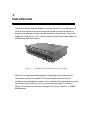
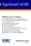
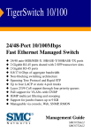
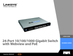
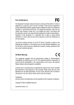
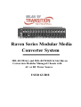
Raven Series Modular Media
Converter System
MIL-RCM16A and MIL-RCM16D 16 Slot Raven
Conversion Modules Managed Chassis with
AC or DC Power Source
USER GUIDE
Regulatory Approval
- FCC Class A
- UL 1950
- CSA C22.2 No. 950
- EN60950
- CE
- EN55022 Class A
- EN55024
Canadian EMI Notice
This Class A digital apparatus meets all the requirements of the Canadian Interference-Causing Equipment Regulations.
Cet appareil numerique de la classe A respecte toutes les exigences du Reglement sur le materiel brouilleur du Canada.
European Notice
Products with the CE Marking comply with both the EMC Directive (89/336/EEC) and the Low Voltage Directive
(73/23/EEC) issued by the Commission of the European Community Compliance with these directives imply conformity to
the following European Norms:
- EN55022 (CISPR 22) - Radio Frequency Interference
- EN61000-X - Electromagnetic Immunity
- EN60950 (IEC950) - Product Safety
One-Year Limited Warranty
Transition Networks warrants to the original consumer or purchaser that each of it's products,
and all components thereof, will be free from defects in material and/or workmanship for a
period of one year from the original factory shipment date. Any warranty hereunder is
extended to the original consumer or purchaser and is not assignable.
Transition Networks makes no express or implied warranties including, but not limited to, any
implied warranty of merchantability or fitness for a particular purpose, except as expressly set
forth in this warranty. In no event shall Transition Networks be liable for incidental or consequential
damages, costs, or expenses arising out of or in connection with the performance of the product
delivered hereunder Transition Networks will in no case cover damages arising out of the product
being used in a negligent fashion or manner.
Trademarks
The MiLAN logo and Transition Networks trademarks are registered trademarks of Transition Networks in the
United States and/or other countries.
To Contact Transition Networks
For prompt response when calling for service information, have the following information ready:
- Product serial number and revision
- Date of purchase
- Vendor or place of purchase
You can reach Transition Networks technical support at:
E-mail: [email protected]
Transition Networks
10900 Red Circle Drive
Minnetonka, MN 55344
United States of America
Telephone: +1.800.526.9267
Fax: : +1.952.941.2322
http://www.milan.com
info@ Transition.com
© Copyright 2006
Transition Networks
Table of Contents
1. Introduction
Features
Intelligent Features
Management Methods
Console and Telnet Management
Web-based Management
SNMP Network Management
Package Contents
2. Hardware Description
Front Panel
Rear Panel
LED Indicators
RS-232 Console
3. Connecting to the Network
Pre-Installation Requirements
Mounting the Device
Desktop Installation
Rack-mounted Installation
Power On
Diagnostic Test
4. Network Configuration
Connecting a Terminal or PC to the Console Port
4-1. Main Menu
4-1-1. Device Settings
4-1-2. Modules Settings
4-1-3. Redundant Power Status
4-1-4. Events Log
4-1-5. SNMP Trap
4-1-6. Secure IP for Telnet, HTTP, and SNMP
4-1-7. Save Current Settings
4-1-8. Factory Default Settings & Reboot System
4-1-9. Reboot System
5. Web-Based Management
5-1. System Login
5-2. System Configuration
5-2-1. Home Page
5-2-2. Modules Settings
5-2-3. IP Configuration
5-2-4. SNMP
5-2-5. Save and Reboot
5-2-5-1. Save Settings
5-2-5-2. Reboot System
5-2-6. Upgrade Firmware
6. SNMP Management
6-1. SNMP Management
7. Technical Specifications
Appendix A. Internet Explorer Setting
1.
Introduction
The Raven Series Modular Media Converter System is a combination of
16-slot host cabinet and various optional media converter modules. A
maximum of sixteen modules can be installed in the cabinet. The power
supply will support AC or DC, with an optional matching power supply for
load sharing and redundancy.
Figure 1-1. The Raven Series Media Converter System
With built-in web-based Management, managing and configuring the
conversion system is simplified. The web browser may be used to
configure and manage the network, from cabinet level management to port
level control and monitoring. Use of a mouse replaces typing of command
strings. The switch can also be managed via Telnet, Console, or SNMP
Management.
1
Features
Cabinet conforms to IEEE 802.3 and IEEE802.3u
Sixteen Converter Module slots
One built-in module with a RS-232 console port and a Fast
Ethernet RJ-45 port for In-band management
Half-duplex mode for backpressure, and full-duplex for
flow-control in management Ethernet port.
System LED indicators: Power Good (A, B), Power Fail (A,
B), System power, CPU Ready, Ethernet port link/activity,
Full duplex
Hot swappable bracket module design
Converter module options:
MIL-RC3412
- 10/100TX to 100FX multi-mode with ST (2 KM)
MIL-RC3413
- 10/100TX to 100FX multi-mode with SC (2 KM)
MIL-RC3413-30
- 10/100TX to 100FX single mode with SC connector (30 KM)
MIL-RC34W13
10/100TX to 100FX single mode, WDM, 1310nm TX with SC
connector (20 KM)
MIL-RC34W15
- 10/100TX to 100FX single mode, WDM, 1550nm TX with SC
Connector (20 KM)
MIL-RC6413SX
- 10/100/1000TX to 1000SX multi-mode with SC (550M)
MIL-RC6413LX
- 10/100/1000TX to 1000LX single mode with SC (10 KM)
Intelligent Features
Web-based management
SNMP network management
Console and Telnet management
Module-specific configuration
Automatic module type display
2
Management Methods
The Raven Series Modular Media Converter System supports the following
management methods:
Console and Telnet Management
Web-based Management
SNMP Network Management
Console and Telnet Management
Console Management is done through the RS-232 Console Port.
Managing the conversion system in this method requires a direct
connection between a PC and the built-in management module. Telnet
management requires a network connection. The default IP address is
192.168.1.77 with a subnet mask of 255.255.255.0. This default address
can be used to login and change the configuration using Telnet.
Web-based Management
The conversion system provides an embedded HTML web server residing
in flash memory. It offers advanced management features and allows
users to manage the conversion system from anywhere on the network
through a standard browser such as Microsoft Internet Explorer or
Netscape.
SNMP Network Management
SNMP (Simple Network Management Protocol) provides a means to
monitor and control network devices, and to manage configurations,
statistic collection, performance, and security.
Data is passed from SNMP agents, which are hardware & software
processes reporting activity in each network device, to the workstation
console used to oversee the network. The SNMP agents return information
contained in a MIB (Management Information Base), which is a data
structure that defines what is obtainable from the device and what can be
controlled.
3
Package Contents
Unpack the contents of the package and verify them against the checklist
below.
Raven Series Chassis (Conversion Modules ship separately)
Power Cord
Four Rubber Feet
RS-232 cable
CD ROM containing Users Guide
Warranty Card
If any item is missing or damaged, please contact your local dealer for
service.
4
2.
Hardware Description
Front Panel
Figure 2.1 below shows the Raven Series Media Converter Chassis fully
populated with sixteen Raven Series Media Converter Modules and one
RS232/Fast Ethernet RJ-45 Management Module.
Figure 2-1. Front Panel for Raven Series Modular Media Converter System
Figure 2-2. Front Panel for Raven
Series Multi-mode ST Module
Figure 2-3. Front Panel for Raven
Series Single Mode SC module
Figure 2-4. Front Panel for Raven
Series Multi-mode SC module
5
Rear Panel
The 3-pronged power plug and power on/off switch are located at the Rear
Panel of the Raven Series chassis, as shown in Figure 2-6. The equipment
will work with AC in the range 100-240VAC, 50-60Hz (AC type power
supply) or DC power in the range 40.5 ~57.0 @ 20A (DC type power
supply).
The conversion system ships standard with one power module and one fan
module.
An additional power module unit is optional for load sharing and
redundancy.
Note: Redundant power modules must be the same type power supply.
AC power and DC power are not available in a single system.
Power Slot B ships with a fan
module standard or an optional
redundant power module.
Figure 2-6.
Rear Panel
6
Power Slot A ships with
either an AC or DC power
module.
LED Indicators
All LED status indicators are located on the front panel of the conversion
system.
There are eight LED-indicators on the CPU Module and six
LED-indicators on each of the Fast Ethernet to Fiber converter modules.
The following tables provide descriptions of the LED statuses and meaning.
They provide a real-time indication of systematic operation status.
Fast Ethernet to Fiber Conversion Modules
LED
Speed (RJ-45)
LINK/ACT
(RJ-45)
Status
Meaning
Link is on 100Mbps mode
On (Green)
On
Ethernet link up
Flashing (Green)
Port is transmitting packets
On
Link is on Full Duplex mode
Off
Link is on Half Duplex mode
On (Green)
Power on
On
Ethernet Link up
Flashing (Green)
Port is transmitting packets
On
Link is on Full Duplex mode
Off
Link is on Half Duplex mode
FDX (RJ-45)
Power
LINK/ACT
(Fiber)
FDX (Fiber)
LK/ACT
On / Flashing
FDX
On / Flashing
Ethernet power link is up / packet
is transmitting
Ethernet link is on Full Duplex
mode / Collision
Table 2-1. Fast Ethernet to Fiber Converter Module LED-indicator statuses and
meaning
7
Management Module
Figure 2-7.Management Module LED-indicators
LED
Status
Meaning
CPU Ready
Flashing (Green)
PWR
On
System kernel is working correctly
System power is ready
On
Power Module A is ready
Off
Power Module A is not ready
On
Power Module B is ready
Off
Power Module B is not ready
On
Power Module A is fail
Off
Power Module A is ready
On
Power Module B is fail
Off
Power Module B is ready
Good A
Good B
Fail A
Fail B
LK/ACT
On / Flashing
FDX
On / Flashing
Ethernet power is link up / packet is
transmitting
Ethernet is link on Full Duplex
mode / Collision
Table 2-2. CPU Module LED-indicator statuses and meaning
8
RS-232 Console
The console port is used to connect a management station or terminal with
the conversion system. Use the RS-232 serial port for out-of-band
management.
Figure 2-8.Management Module Serial Port Pinouts
9
3.
Connecting to the Network
Pre-Installation Requirements
You will need the following prior to installing the hardware:
•
•
•
•
•
•
PC or Workstation with 10/100BASE-TX Ethernet card or RS-232
serial port: Your PC must have a standard Ethernet interface or Serial
port to connect to the Device.
Ethernet UTP cable with RJ-45 connector or DB-9 RS-232 Serial
cable: Check if the cable and connectors work properly.
A power outlet: 100 to 240V AC at 50 to 60 Hz or DC power.
Make sure that the Device power is accessible and power cords can be
connected easily.
Dedicated power supply: Use dedicated power circuits or power
conditioners to supply reliable electrical power to the network devices.
A dry cool place: Keep the Device away from moisture. Avoid direct
sunlight, heat source, and high amounts of electromagnetic
interference, all of which will adversely affect the performance of the
Device.
Mounting tools: If you intend to mount the device on a rack, make sure
you have all the tools, mounting brackets, screws.
Mounting the Device
The Raven Series Modular Media Converter System is suitable for use in
an office environment where it can be rack-mounted in standard EIA
19-inch racks or used in a standalone configuration.
10
Desktop Installation
Set the conversion system on a sufficiently large flat space with a power
outlet nearby. The surface where you put your conversion system should
be clean, smooth, level, and sturdy. Provide enough clearance around the
conversion system to allow attachment of cables, power cord and air
circulation.
Attaching Rubber Feet
A. Make sure mounting surface on the bottom of the conversion system is
grease and dust free.
B. Remove adhesive backing from the rubber feet.
C. Apply the rubber feet to each corner on the bottom of the conversion
system. These footpads can prevent the conversion system from
shock/vibration.
Figure 3-1. Attaching rubber feet to each corner on the bottom of the conversion
system
11
Rack-mounted Installation
The Raven Series Media Converter System includes a rack-mount kit that
allows it to be mounted in an EIA standard size, 19-inch rack.
Perform the following steps to rack mount the conversion system:
A. Position one bracket to align with the holes on one side of the
conversion system and secure it with the bracket screws. Then attach
the remaining bracket to the other side of the conversion system.
Figure 3-2. Attach mounting brackets with screws
12
B. After attaching both mounting brackets, position the conversion
system in the rack by lining up the holes in the brackets with the
appropriate holes on the rack. Secure the conversion system to the
rack with a screwdriver and the rack-mounting screws.
Figure 3-3. Mounting the Raven Series Media Converter System in an EIA
standard 19-inch Rack
Note: For proper ventilation, allow at least 4 inches (10 cm) of clearance
on the front and 3.4 inches (8 cm) on the back of the conversion system.
This is especially important for enclosed rack installations.
13
Power On
Connect the power cord to the power socket on the rear panel of the
conversion system. Connect the other end of the cord to an appropriate
power outlet.
Press the power On/Off switch to the On position and check the power
indicator on the front panel to see if power is properly supplied.
Diagnostic Test
The system will automatically perform a diagnostic test once the
installation is completed and power is applied to the device.
When the Power LED is on for 4 seconds, the CPU Ready LED will begin
flashing, indicating the system is ready. If the CPU LED is a steady light,
the diagnostic test has failed.
Contact MiLAN Technical Support for
assistance.
14
4.
Network Configuration
Connecting a Terminal or PC to the Console Port
The serial console port is a male DB-9 connector that enables a
connection to a PC or terminal for monitoring and configuring the
conversion system.
Figure 4-1. Connecting the Raven Series Media Converter System to a terminal
via RS-232 cable
Use the supplied RS-232 cable with a female DB-9 connector to connect a
terminal or PC to the console port. The terminal or PC to be connected
must support a terminal emulation program.
15
After the connection between the conversion system and PC is finished,
turn on the PC or terminal and run a terminal emulation program or
Hyper Terminal to match the following default characteristics of the
console port:
Baud Rate: 9600 bps
Data Bits: 8
Stop Bit: 1
Parity: none
Flow control: None
Figure 4-2. The setting of communication parameters
In order to telnet from a directly connected PC to the Device, the IP
address of the PC must be in the same class as the Device.
The default
IP address of the Device is 192.168.1.77, with a subnet mask of
255.255.255.0.
A recommendation is to set the PC IP address to
192.168.1.156 with a subnet of 255.255.255.0.
Then using a telnet
program on your PC telnet to address 192.168.1.77.
The default user
name is root with the default password of root.
After you have entered the parameter settings, press the “ Enter “ Key and
the Main Menu of console management appears.
16
4-1. Main Menu
Figure 4-3. The Main Menu
At the prompt, type go and press the Enter key to access the Main
Menu.
The following sections describe the options available in the Main
Menu and their associated sub-menus.
To select a menu item, enter the appropriate character (1-6, S, D, R or Q),
and then press the Enter key to select the item.
17
4-1-1. Device Settings
This menu enables the user to change the conversion system settings.
Saving and rebooting the conversion system is necessary to have the
new configuration take effect.
To configure Device Settings, select 1 and then press the Enter key
from the main menu.
Enter the number or letter, and then press Enter to
select an item.
Note: The Version (0.1), MAC Address (0.2) and System Up Time (0.3)
fields are fixed and cannot be updated.
System Name (1):
64 characters can be used to give the conversion
system a unique name in order to distinguish it on the network.
System Location (2):
64 characters can be used to describe the
location of the conversion system.
System Contact (3):
64 characters can be used to list contact
information for the conversion system.
IP Address (4):
The user can change the IP Address for the conversion
18
system to a unique IP address. The factory default IP address is:
192.168.16.1.
Subnet Mask (5): The user can change the Subnet Mask for the
conversion system to a unique Subnet Mask. The factory default Subnet
Mask is 255.255.255.0.
Default Gateway (6): The user can change the IP address of the default
gateway if packets are being sent to another IP network. The factory
Default Gateway is 192.168.16.254.
NOTE: You must select the Save option in the Main Menu, then Reboot
the system in order for these features to take effect.
Change User Name / Password (7): The user can enter up to 16
characters for the user name and password. The default user name and
password is root.
19
Console Login Enabled (8): The user may enable (Yes) or disable (No)
console management security. The user name and password are required
to enable console management.
The default setting is disabled (No).
Get Request Community (9): 32 characters can be used to enter a
community string. The default community string is public.
20
Set Request Community (A): 32 characters can be used to enter a
community string. The default community string is public.
21
4-1-2. Modules Settings
This menu enables the user to change the media converter module
operation mode.
To configure Modules Settings, select 2 and then press the Enter key
from the main menu.
Enter the number or letter, and then press Enter to
select an item.
Enter the module position number (1 - 16) and then press Enter to
change the settings for that module.
Note: The Plugged (0.1), UTP Link (0.2), UTP Speed/Duplex (0.3), Fiber
Type (0.4), Fiber Link (0.5) and Fiber Duplex (0.6) fields are fixed and
cannot be updated.
UTP Speed/Duplex (1): Indicates whether in auto-negotiation mode or
forced 10 or 100, FDX or HDX.
22
Fiber Duplex (2): Indicates the duplex mode FDX or HDX of the fiber
port.
Flow Control (3): Indicates whether flow control is enabled or disabled
on the port.
LLF (4): Indicates whether LLF is enabled or disabled on the module.
LLF Direction (5): Indicates which direction LLF is enabled, either UTP to
Fiber or Fiber to UTP.
Note (6): This field allows the network administrator to label the module
with information such as what devices the module interconnects.
23
4-1-3. Redundant Power Status
This menu enables the user to view the current status of the conversion
system Power Modules.
To view Redundant Power Status, select 3 and then press the Enter
key from the main menu.
This screen shows the current redundant power supply status.
The
conversion system has two power modules; left-hand is Power A,
right-hand is Power B.
24
4-1-4. Events Log
This menu enables the user to change the conversion system Event Log
settings and view Event Log records.
To access the Events Log options, select 4 and then press the Enter key
from the main menu.
Enter the number or letter, and then press Enter to
select an item.
Event Log Enabled (1):
The user may enable or disable event log
recording.
A maximum of 4095 event records will be stored by the
conversion system.
Show Event Log (2):
The user can view the event log records after the
events log has been enabled.
Delete All Event Log (3):
The conversion system will erase all event
log records stored in the Flash Rom.
25
4-1-5. SNMP Trap
This menu enables the user to change the SNMP Trap station settings.
To configure SNMP Trap, select 5 and then press the Enter key from the
main menu. Enter the number or letter, and then press Enter to select an
item.
Send Trap (1):
The user can enable or disable the SNMP Trap function.
Trap Community (2):
32 characters can be used to enter the trap
community string.
The trap station must have the same community
string.
The default community string is public.
IP Address (3-6):
The user can enter the IP address for the stations
authorized to receive the Trap information.
26
4-1-6. Secure IP for Telnet, HTTP and SNMP
This menu enables the user to change the management security settings
for Telnet, Web-based Management and SNMP.
To configure Secure IP, select 6 and then press the Enter key from the
main menu.
The user can enter enable or disable security for the conversion system.
A maximum of 4 IP addresses can be entered of stations authorized to
manage the conversion system when management security is enabled.
27
4-1-7. Save Current Settings
This menu enables the user to save the configuration settings for the
conversion system.
To Save Current Settings, select S and then press the Enter key from
the main menu. Rebooting the conversion system is necessary to have
the new configuration take effect.
4-1-8. Factory Default Settings & Reboot System
This menu enables the user to reset the Factory Default Settings for the
conversion system.
To Reset the Factory Default Settings, select D and then press the
Enter key from the main menu. Rebooting the conversion system is
necessary to have the factory default settings take effect.
The
conversion system will be inoperative while performing this action.
Note:
The IP Address and Subnet Mask settings will not be reset to the
factory default. These settings must be manually reset in the Device
Settings menu.
4-1-9. Reboot System
This menu enables the user to Reboot the conversion system to have a
new configuration take effect.
To Reboot the conversion system, select R and then press the Enter key
from the main menu. Rebooting the conversion system is necessary to
have new configuration settings take effect. The conversion system will
be inoperative while performing this action.
28
5.
Web-Based Management
This section introduces the configuration and functions of the web-based
management of the Raven Series Modular Media Converter System.
The conversion system provides an embedded HTML web site residing in
flash memory. It offers advanced management features and allow users
to manage the device from anywhere on the network through a standard
browser such as Internet Explorer or Netscape.
Web-based management supports Internet Explorer 5.0 and later
versions. It is based on Java Applets with an aim to reduce network
bandwidth consumption, enhance access speed and present an easy
viewing screen.
Note: By default, Internet Explorer 4.0 does not allow Java Applets to
open sockets. The user must explicitly modify the browser setting to
enable Java Applets to use network ports. (See Appendix A for
instructions to modify the setting)
29
5-1. System Login
1. Launch Internet Explorer or Netscape.
2. Type http:// and the IP address of the conversion system in the
Location or Address field.
The default IP Address is 192.168.16.1.
3. Press Enter.
Figure 5-1: The Password Window
4. In the login screen, type the user name and password. The default
is “ root ” for both.
5. Press Enter or Click OK and the Home Page screen for web-based
management will appear.
30
5-2. System Configuration
31
5-2-1. Home Page
The Home page screen displays the configuration of the Raven Series
Modular Media Converter System.
System Name: An administratively assigned name of the managed unit
that can be modified in SNMP page.
System Location: The physical location of this managed unit (e.g.,
laboratory, 3 floor) that can be modified in SNMP page.
System Contact: The contact person for this managed unit that can be
modified in SNMP page.
System Up Time: The time since the managed unit was re-initialized is a
read only field.
IP Address: The IP address of the managed unit that can be modified in
IP Config page. Default is 192.168.16.1.
rd
Subnet Mask: The subnet mask of the managed unit that can be modified
in IP Config page. Default is 255.255.255.0.
Default Gateway: The default gateway of the managed unit that can be
modified in IP Config page. Default is 192.168.16.254.
MAC Address: The MAC address of the managed unit is a read only
field.
Firmware Version: The firmware version of the management unit is a
read only field. You can upgrade to the new firmware on-line if a new
version is released.
Note: By default, IE4.0 does not allow Java Applets to open sockets. The
user must explicitly modify the browser setting to enable Java Applets to
use network ports. (See Appendix A for instructions to modify the setting).
32
5-2-2. Modules Settings
The Modules Settings page shows the modules that have been installed into the
conversion system and the current settings for each.
TX Speed/Duplex: The user can select Auto negotiation, 100Full,
100Half, 10Full, 10Half. Default is Auto-negotiation.
FX Duplex: The user can select 100Full or 100Half. The default is
100/Full.
33
Flow Control: The user can select enabled (checked) or disabled
(unchecked).
The default is enabled.
LLF - Link Loose Forward:
The user can select to have LLF enabled
(checked) or disabled (unchecked).
When LLF is enabled, the controlled
port will auto-disconnect if the controlling UTP or Fiber link is down. The
direction can be UTP controls Fiber or Fiber controls UTP. The LLF
default is disabled and UTP controls Fiber.
34
5-2-3. IP Configuration
This screen enables the user to change the IP address, subnet mask and
default gateway of the managed node or change the user name and
password.
Enter a new IP address, subnet mask or default gateway in the
corresponding edit box and then Click Apply.
To change the user name or password for the managed node:
1. Click the "Change Password" checkbox.
2. Enter the user name in "Username" edit box.
3. Enter the same password in "Password" and "Confirm Password"
edit boxes.
4. Click the Apply button.
You must reboot the conversion system for new configuration settings to
take effect if any of the IP address, subnet mask or default gateway fields
have been changed.
35
5-2-4. SNMP
This screen enables the user to change the System Descriptive fields,
Community String and SNMP Trap configuration.
System Name:
64 characters can be used to give the conversion
system a unique name in order to distinguish it on the network.
System Location:
64 characters can be used to describe the location
of the conversion system.
System Contact:
64 characters can be used to list contact information
for the conversion system.
Get Request Community: 32 characters can be used to enter a
community string. The default community string is public.
Set Request Community: 32 characters can be used to enter a
community string.
Note: The Get Request Community and Set Request Community
parameters must be set correctly to perform "get request" from the
management unit and "set request" to the management unit.
36
5-2-5. Save and Reboot
This screen enables the user to save new configuration settings and
reboot the conversion system to have a new configuration take effect.
5-2-5-1. Save Settings
Save the current settings by clicking the Save Current Settings
checkbox, and then press the corresponding Apply button. The current
settings will take effect at the next reboot of the Device.
To reset the factory default settings, click the Factory Default Settings &
Reboot checkbox, and then press the corresponding Apply button. The
factory default settings will take effect.
The conversion system will be
inoperable during this process.
Please wait a moment to continue to
operate the web-based management.
5-2-5-2. Reboot System
To reboot the conversion system, click the Reboot System checkbox,
and then press the corresponding Apply button. The conversion system
will be inoperable during this process.
Please wait a moment to continue
to operate the web-based management.
37
5-2-6. Upgrade Firmware
This screen allows the user to perform an upgrade of the conversion system
firmware on-line.
1. Users can choose http: or ftp: to download a new version of firmware.
2. Enter the password in the "Password" edit box.
3. Enter the file downloaded in the "File Path" edit box or press the
Browse button to select the file.
4. Press the Upgrade button.
5. The conversion system will automatically reboot after the firmware
has been upgraded.
6. The web browser session is disconnected during the rebooting of the
Device.
Re-establish the web session once the conversion system
has finished rebooting.
38
6.
SNMP Management
This section describes how to configure and manage the device by
accessing Management Information Base (MIB) objects with the SNMP
protocol.
6-1. SNMP Management
The conversion system's MIB options are accessible through SNMP.
SNMP performs all operations using the “GET”, “GETNEXT” and “SET”
commands, instead of defining a large set of commands. The SNMP agent
that resides on the conversion system can respond to MIB-related queries
being sent by the network management software.
The SNMP agent gathers data from the MIB, which keeps information
about device parameters and network data. The agent can send traps, or
notification of certain events, to the manager.
Figure 6-1: SNMP Network
39
The SNMP manager uses information in the MIB to perform the operations
described in the table below:
Operation
Description
GET
Retrieve values of SNMP objects from a network
device.
GETNEXT
Specifies an SNMP object in a network device and
then retrieves information about the next few
SNMP objects in the device.
SET
Modifies and stores values of SNMP objects in a
network device.
GET
RESPONSE
The reply to GET, GETNEXT, and SET commands
sent by an SNMP agent.
TRAP
A message sent by an SNMP agent to an SNMP
manager indicating some event has occurred.
Table 6-1. The commands of SNMP management
40
7.
Technical Specifications
This section provides the specifications of the Raven Series Modular
Media Converter System.
Standards
Compliance
IEEE 802.3 10BASE-T Ethernet,
IEEE 802.3u 100BASE-TX/FX Ethernet,
ANSI/IEEE standard 802.3 N-Way
Auto-negotiation
Max Forwarding
Rate and
14,880 pps per Ethernet port,
148,800 pps per Fast Ethernet port
Max Filtering
Rate
LED Indicators
System: Power A, B (Good, Fail), CPU Ready
Module: TX Speed, TX Link/Activity, TX Full
Duplex, Fiber Link/Activity, Fiber Full Duplex,
Power
Network Cables
10Base-T: 2-pair UTP/STP Cat. 3, 4, 5 cable
EIA/TIA-568 (100m)
100Base-TX: 2-pair UTP/STP Cat. 5 cable
EIA/TIA-568 (100m)
100Base-FX: 50/125, 62.5/125 micron Multi-mode
fiber-optics (2Km)
8/125, 9/125 micron Single mode fiber-optics (5,
30, 60Km)
Dimensions
448mmx 279mm x 89mm (L x W x H)
41
Operational
Temperature
0ºC to 45ºC (32ºF to 113ºF)
Operational
Humidity
10% to 90% (Non-condensing)
Power Supply
AC Input rate: 100~240VAC, 50~60Hz (AC Type
Power Module)
DC Power Input: 40.5 ~57.0 @ 20A (DC type
power supply)
Notice: AC power and DC Power cannot be
used in conjunction within the same
conversion system chassis.
Power
Consumption
Maximum power consumption of a fully loaded
chassis is 200 Watts.
EMI
FCC Class A, CE Mark
Safety
cUL, UL
42
Appendix A.
Internet Explorer Setting
When using IE 4.x and later versions, you must modify the browser setting
to enable Java applets to use network ports. Internet Explorer 5.0 detailed
instructions follow:
Select Tools from the menu bar and then select Internet Options… to
enable Java applets.
Step 1:
Select the Security tab.
43
Step 2:
Step 3:
Click on Trusted Sites.
Click the Sites button.
44
Step 4:
Add the IP address of the
conversion system to the Add this Web
site to the Zone field, and then click
Add.
Step 5: Disable Require server
verification for all sites in this zone by
deselecting the checkbox, and then click
the OK button to return to Internet Options.
45
Step 6: Click the Customer Level
button on the Internet Options screen.
Step 7: Scroll through Security Settings
to locate Java.
46
Step 8: Select Custom under Java
permissions.
Step 9:
Click the Java Custom
Settings… button.
47
Step 10: Select the Edit
Permissions tab.
Step 11:
Select Enable under
Run Unsigned Content.
48
Transition Networks, Inc.
10900 Red Circle Drive
Minnetonka, MN 55343 USA
Tel 952.942.7600
Or 800.526.9267
Fax 952.941.2322
[email protected]
http://www.transition.com
49