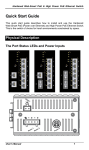
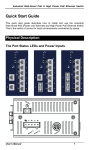
1
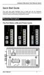
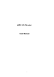
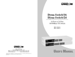
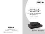
For full coverage of your warranty, be sure
to register your product using the enclosed
registration card.
Smart-Chassis/16
16 Bay Managed
Media Converter Chassis
FEP-682116
908 Canada Court
City of Industry, CA 91748 U.S.A.
Phone: 626.964.7873 or 800.346.6668 Fax: 626.964.7880
www.unicomlink.com
e-mail: [email protected]
©UNICOM 2003. UNICOM and “A Network Systems Solution” are trademarks of UNICOM Electric, Inc.
All rights reserved. Specifications subject to change without notice.
Rev: 05.03
USER’S MANUAL
1. Introduction
Congratulations on purchasing a quality UNICOM product.
Unicom’s Smart-Chassis/16 represents the newest, most advanced generation
of signal conversion technology.
The Smart-Chassis/16 is a heavy-duty enclosure that provides compact
management of up to 16 optional modular converter units. This management
creates a flexible networking environment. Also, all converter bays are isolated
from the power bus making all converters hot- swappable for minimal system
downtime.
Figure 1-1
the Smart-Chassis/16
Managing and configuring the Smart-Switch/16 is easy with its built-in Webbased Management features, Via a Web Browser. You can enact global as well
as specific bay changes. The Smart-Chassis/16 can also be managed via
Telnet, Console, or third party SNMP Management.
Features
Conforms to the IEEE 802.3, 802.3u, 802.3ab, and 802.3z Standard
Capacity for sixteen converters and two power supplies
Modules and CPU module are hot-swappable
Supports Fast Ethernet and Gigabit modules, Single Mode or Multi-Mode
AC/DC power with Redundant
HTTP, Telnet security
IP address security for management station
Firmware upgrade via web interface
Link Lost Forwarding (LLF)
Module identification
SNMP, Web, Telnet, console management
Event log and SNMP Trap support
SNMP MIB II and private MIB supports
EIA RS-310C 19 “ standard
Software Features
Management
Telnet, Web, and Console (RS-232)
Web/Telnet
Web and Telnet function can be enabled or disabled.
MIBS
RFC 1213 MIB II, Private MIB
Link down, Link up, Power module status change,
SNMP Trap
authorization Fail, Module plug in and plug out, chassis
configuration change, module configuration change.
Software
Upgrade
Firmware upgrade via web interface
Each module supports LLF feature. It can be set through
the web interface or the CLI menu.
Link Lost
LLF Mode TX Fiber: TX port link down, the fiber port
Forwarding
will be forced down
LLF Mode Fiber TX: Fiber port link down, the TX port
will be forced down
TX port: IN-good / In-bad packet counter, out-good /out-
Packet counter
bad packet counter, collision counter
Fiber port: IN-good / In-bad packet counter, out-good
/out-bad packet counter, collision counter
SNMPTrap Node
IP security
Module notice
Events log
Up to 4 Trap nodes.
It supports IP security for telnet, HTTP and SNMP
access. Up to 4 IP nodes when security is enabled.
Each module can add notices for information allocation
(up to 32 characters).
Up to 4095 event records. They can be reviewed via the
CLI or Web interface.
Management Methods
The Smart-Chassis/16 supports the following management methods:
Console and Telnet Management
Web-based Management
SNMP Network Management
Console and Telnet Management
Console Management is done through the RS-232 Console Port. This requires
a direct connection between PC and the Chassis. The Telnet management is
done through the network. Once the Chassis is on the network, you can use the
Telnet program to Log in and modify the configuration.
Web-based Management
The Smart-Chassis/16 provides an embedded HTML web program in flash
memory. It offers advanced management features and allows users to manage
the chassis from anywhere on the network through a standard browser such as
Microsoft Internet Explorer. For more information, see Section 5 Web-Based
Management.
SNMP Network Management
SNMP (Simple Network Management Protocol) provides a way to monitor and
control network behaviors, such as configurations, statistic collection,
performance, and security.
Data is collected by SNMP agents, which are hardware and software processes
reporting activity in each network device. The agents report information
contained in an MIB format (Management Information Base), which is a data
structure that defines what is obtainable from the device and what can be
controlled.
Package Contents
Unpack the carton of the Smart-Chassis/16 and verify them against the
checklist below.
Smart-Chassis/16
Power Cord
Four Rubber Feet
RS-232 cable
User Guide
Smart-Chassis/16
RS-232 cable
Rubber Feet
User Guide
Rack-mounted Kit
Power Cord
Figure 1-2. Package Contents
If any item is missing or damaged, please contact your local dealer for service.
2. Hardware Description
The Smart-Chassis/16 is a modular unit that contains 16 module slots and 2
power slots. Both an RS-232 port, used for Out-of-Band Management, and an
Ethernet RJ-45 connector, for In-Band Management, are on the front panel.
Front and Rear Panel
Figure 2-1 shows the front panel of Smart-Chassis/16 filled with modules (16
modules, sold separately).
Figure 2-1. Front Panel
The 3-pronged power plug is located at the Rear Panel of the SmartChassis/16 as shown in Figure 2-2. The power is AC in the range 100-240VAC,
50-60Hz (AC type power supply) or DC power in the range 40.5 ~57.0 @ 20A.
(DC type power supply). The Factory Default is one power and fan module but
another power module may be added for power redundancy.
[Notice] AC power and DC Power cannot be installed simultaneously.
Power Slot B
Power Slot A
with fan unit
with AC Power
Figure 2-2. Rear Panel of the Smart-Chassis/16
LED Indicators
All LED status indicators are located on the FRONT panel of the chassis. They
provide real-time indication of system and operational status. The ports for
connections to other devices and networks are also on the front panel.
CPU Panel
LED
Status
Meaning
CPU Ready
Green
(Blinking)
System kernel is working correctly
PWR
Green
Power on
Green
Power Module A is ready
Off
Power Module A is not ready
Green
Power Module B is ready
Off
Power Module B is not ready
Orange
Power Module A has failed or is not present
Off
Power Module A is ready
Orange
Power Module B has failed or is not present
Off
Power Module B is ready
Green
Ethernet port is connecting with the device.
Blinking
The port is receiving or transmitting data
Yellow
Ethernet is link in Full Duplex mode
Blinking
Packet collision occurring (half-duplex)
T bl 2 1 D
i ti
Good A
Good B
Fail A
Fail B
LK/ACT
FDX
f th CPU LED
3. Connecting to the Network
This chapter provides the installation procedure and instructions for assigning
IP addresses.
Pre-Installation Requirements
Before you start the hardware installation, make sure your installation
environment has the following items:
PCs with 10/100Base-TX Ethernet cards: the PC must have a standard
Ethernet interface to connect with the chassis
UTP cable with RJ-45 connector: Verify that the cable and connectors
are working properly.
Fiber cable with SC/ST/MT-RJ connector: Verify that the cable and
connectors are the proper types.
A power outlet: 100 to 240V AC at 50 to 60 Hz or DC power. Make sure
that the chassis' power is accessible and that cables can be connected
easily.
Dedicated power supply: Use dedicated power circuits or power
conditioners to supply reliable electrical power to the network devices.
A dry cool place: Keep the chassis away from moisture. Avoid direct
sunlight, heat sources, and area with a high amount of electromagnetic
interference.
Mounting tools: If you intend to mount the chassis on a rack, make sure
you have the tools and supplies, such as mounting brackets and screws.
Mounting the Chassis
The Smart-Chassis/16 is suitable for an office environment where it can be
rack-mounted in standard EIA 19" racks or as a standalone.
Desktop Installation
This surface should be clean, smooth, level, and sturdy. Make sure there is
enough space around the chassis to provide air circulation and allow
attachment of cables and cords.
Rack Mounting
The Smart-Chassis/16 comes with a rack-mounting kit and can be mounted in
an EIA standard size, 19" Rack. The chassis can be placed in a wiring closet
with other equipment. Perform the following steps to rack mount the chassis:
A_
Position one bracket to align with the holes on one side of the chassis and
secure it with the bracket screws. Then attach the remaining bracket to the
other side.
Figure 3-1. Attach mounting brackets with screws
B_
After attaching both mounting brackets, position the chassis in the rack by
lining up the holes in the brackets with the appropriate holes on the rack.
Secure the chassis to the rack with a screwdriver and the rack-mounting
screws.
Figure 3-2. Mounting the Smart-Chassis/16 in an EIA standard 19" Rack
[Note] For proper ventilation, allow at least 4 inches (10 cm) of clearance on
the front and 3.4 inches (8 cm) on the back of the chassis. This is especially
important for enclosed rack installations.
Power On
After all network cables are connected, plug the power cord into the power
socket on the back panel and the other end into a power outlet. Turn the power
on using the power switch on the back panel.
Check the front panel Power indicator to see if power is properly supplied. The
chassis uses a universal power supply that requires no additional adjustment.
Diagnostic Test
After the installation is completed and AC power is applied to the chassis, the
system will automatically perform a diagnostic test
Once the Power LED is on for 4 seconds, the CPU Ready LED will start
blinking signifying the system is Ready. If the CPU Ready LED stays lighted,
this signifies a system crash. In this case, restart the chassis.
Connecting the Chassis via Local console or Telnet
The serial console port is a male DB-9 connector that enables a connection to a
PC or terminal for monitoring and configuring the Chassis.
Use the supplied RS-232 cable with a female DB-9 connector to connect a
terminal or PC to the console port. The terminal or PC to be connected must
support the terminal emulation program.
For the telnet management, you must set the chassis IP address into the same
class as your PC. For example if the Factory default IP address is 192.168.1.1
then set the PC IP address to 192.168.1.156.
Default login user name: root
Default login password: root
Default IP address: 192.168.1.1
After connecting to the Console port, turn on the PC or terminal and configure
its communications parameters to match the following default characteristics
of the console port:
Baud Rate: 9600 bps
Data Bits: 8
Stop Bit: 1
Parity: none
Flow control: None
Figure 3-4. The setting of
communication parameters
You can run Hyper Terminal or a terminal emulation program using the above
settings for Console Management. After you have finished parameter settings,
press Enter on your keyboard and the Main Menu appears.
Figure 3-5. The Main Menu
4. Console Management
In this chapter, we will describe each function of console management. Console
management mode is a Command Line Interface. You can enter the function
number to configure the function.
Device Setting
Select Device settings (Type “1” and press “Enter”) from the main menu. It
displays the list of device setting items, ex: system name, location, IP, etc. You
can enter the number to modify the value.
Device Settings interface
[Note] The items “0.1,0.2, and 0.3” cannot be modified.
1. System Name: you can set a system name for this chassis. (Maximum
length of characters is 64). Default is Device.
2. System Location: the description for the location of chassis.
(Maximum length of characters is 64).
3. System contact: the description of the contact people for the chassis.
(Maximum length of characters is 64).
4. IP address: the IP address of the chassis. The default IP is
5. Subnet mask: the default value is 255.255.255.0.
6. Default Gateway: the default value is 192.168.1.254.
7. Change User/Password: the default username and password is
“root”. You can change the username and/or password.
8. Console Login Enabled: This feature allows you to enable or disable
console management security. The default value is “No”. When you enter
console management mode, you don’t need to enter the username and
password. If the value is “Yes”, you'll need to enter the username and
password to login to the console management mode.
9. Get Request Community: the community string for GET. The default
value is “Public”.
Set Request Community: the community string for SET. The default
value is “Public”.
HTTP Enable: enable or disable HTTP function.
Telnet Enable: enable or disable Telnet function.
Remember when returning to the Main Menu to Save the modified settings and
then reboot the chassis. You may have to press Enter again when the chassis
is finished rebooting.
Modules Settings
You can configure each module's operation mode. Enter “2” and press “Enter“
from the main menu interface. The system will ask you to select the module for
configuration. Enter the number of the module, ex: 6, and then press “Enter”.
Modules setting select interface
After selecting the module, you will see the module configuration interface as
follows. Here you only can configure 1 to 6 selections. The 0.1 to 0.6 is read
only information. Enter the selection number to modify the value.
Module setting interface
1. Module enable/disable: to enable or disable module function. The
default is “Enable”.
2. LLF Direction: When the UTP or Fiber is LINK DOWN, it will force the
other ports to automatically disconnect. The forced direction depends on
whether the UTP controls Fiber port or Fiber controls UTP port. The LLF
default is disabled when UTP controls Fiber.
3 UTP Speed/ Duplex: configure UTP port speed and mode The default
is “Auto-negotiate”.
4. Fiber Speed/Duplex: configure Fiber port speed and mode. The
default is “100M” and “Full”.
5. Reset to default: reset the module configuration to default value.
6. Note: enter a short description or note for this module.
Redundant Power Status
It shows current power supply status. The chassis has two slots for Power
modules; the left side is power A and the right is power B. In the main menu
interface, enter “3” and press enter. You will see as the following figure:
Redundant Power Status interface
Events Log
The system provides 4095 event records.
1.
Event Log Enabled: the System will start recording events when it is
“enabled”.
2.
Show Event Log: to view event log records. You must enable “Event Log
Enable” function.
3.
Delete All Event Log: erases all records stored in system Flash ROM.
Event Log interface
SNMP Trap
Configuring the SNMP Trap station. You can configure up to 4 IP addresses as
a trap.
Send Trap: Enable or Disable Trap function.
Trap community: the default community string is “public”. The Trap
station must have the same community string and can get trap information
from this Chassis. The maximum trap community string length is 32
characters.
Trap IP 1~4: assigns the trap station’s IP address. Only the authorized
station can receive the Trap information.
SNMP Trap interface
Secure IP for Telnet, http, and SNMP
Users can manage the security settings for Telnet, Web management, and
SNMP. The maximum number of stations is 4. If the function is enabled then
only the authorized station with the correct IP address can manage this
chassis.
Secure IP interface
1. Secure IP for Telnet: enable or disable the secure Telnet IP function.
2. Secure IP for HTTP: enable or disable the secure HTTP IP function.
3. Secure IP for SNMP: enable or disable the secure SNMP IP function.
Secure IP 1~4: assign the IP that can manage the chassis through
Telnet, HTTP and SNMP.
Save Current Settings
After modification, the parameters are not saved automatically. Saving will store
all changes in system Flash ROM. All values will take effect after reboot. Enter
“R” and press “Enter” key to save the current settings.
Factory Default Settings & Reboot System
Resets the system configuration to factory default settings. After reboot, the
system configuration will set to default value. Enter “D” and press the “Enter”
key. There are three options that you can choose to keep the current value or
reset to default.
Port Counter: enter “y” to reset port counter or “n” to keep current value.
All module settings: enter “y” to reset all module settings or “n” to keep
present settings.
IP settings: enter “y” to reset IP address to factory default IP or “n” to
keep present IP address.
Factory Default Settings interface
Reboot System
To reboot the system without resetting the system configuration to default,
Enter “R” and press “Enter” key.
5. Web-Based Management
About Web-based Management
The Smart-Chassis/16 supports embedded HTML web management. It offers
advanced management features and allows users to manage the chassis from
anywhere on the network through a standard web browser.
The Web-Based Management supports Internet Explorer 5.0 and later versions.
It is based on Java Applets and strives to reduce network bandwidth
consumption, enhance access speed, and present an easy viewing screen.
[Note] By default, IE4.0 does not allow Java Applets to open sockets. The user
has to explicitly modify the browser setting to enable Java Applets to use
network ports. (See Appendix A) You don’t need to change any configurations if
you use the Netscape browser.
System Login
Follow the step below to login to the system.
1.
Start Internet Explorer
2.
Type” http://” and “the IP address of the Smart-Chassis/16” (for
example, the Factory default is 192.168.1.1) and press “Enter” key.
The authentication Window
3.
The authentication screen appears.
4.
Key in the user name and password. The default is “ root ” for both.
5.
Press “Enter” or Click ”OK”. The Home screen of the Web-based
management appears.
Web management Home interface
The Home page displays the configuration of the Smart-Chassis/16.
System Name: An administratively assigned name of the managed unit
that can be modified in the SNMP page.
System Location: The physical location of this managed unit (e.g.,
laboratory, 3rd floor) that can be modified in the SNMP page.
System Contact: The contact person for this managed unit that can be
modified in the SNMP page.
System Up Time: The time since the managed unit was re- initialized.
This is read only.
IP Address: The IP address of the managed unit that can be modified in
the IP Config page. Factory Default is 192.168.1.1.
Subnet Mask: The subnet mask of the managed unit that can be
modified in the IP Config page. Default is 255.255.255.0.
Default Gateway: The default gateway of the managed unit that can be
modified in the IP Config page. Factory Default is 192.168.1.254.
MAC Address: The MAC address of the managed unit. It is read only.
Firmware Version: The firmware version of the management unit. It is
read only. Upgrades can be done online.
[Note] By default, IE4.0 does not allow Java Applets to open sockets. The user
has to explicitly modify the browser setting to enable Java Applets to use
network ports. (See Appendix A).
Modules settings
The Modules settings show the modules that are installed on the SmartChassis/16. The modules settings has 4 parts for configure – module, UTP
Port, Fiber Port, and Note.
Modules Settings interface
Module
State: this displays the module's current status. You can enable or
disable the module state.
Mode: It shows the module mode. The mode was Auto-detected by the
system when installed on the chassis.
LLF Direction: When the UTP or Fiber link is down, this function will
force the other ports to automatically disconnect. The forced way depends
on whether the UTP controls Fiber or Fiber controls the UTP port. The LLF
default is disabled and UTP controls Fiber.
UTP Port
Link: This shows the UTP port's current link status.
Nego: Selects the negotiation mode. “Auto” means the system
automatically selects the speed “Force” means the user can select the
speed. The default is Auto.
Speed: You can select the speed of the port. Make sure the “Nego”
column is “Force”. Otherwise, the speed function is disabled.
Duplex: You can select the Duplex mode. Make sure the “Nego” column
is “Force”. Otherwise, the duplex function is disabled.
Fiber Port
Link: It shows the UTP port's current link status.
Nego: Selects the negotiation mode.
Speed: You can select the speed of port.
Duplex: You can select the Duplex mode.
Note: fill in any note for this module. The maximum character length is 32.
After modification, click the
Apply
button to apply the new settings.
Port Counter
You can see all port counter information here. To reset the port counter, click
Reset
button.
Port Counter interface
IP Config
Here users can change the IP address, subnet mask, default gateway, login
username, and password.
To change the user name or password following steps below:
Click the "Change Password" checkbox
Enter the user name in "Username"
Enter the same password in "Password" and "Confirm Password"
Click the
button
You must reboot system to apply the new settings.
IP Config interface
SNMP
Here users can configure the system name, system location, system contact,
the "get request", and the "set request" community name. The default value of
"get request" community is public. The default value of the "set request"
community is public. You must set these two parameters correctly to perform
"get request" from the management unit and "set request" to the management
unit. Click
button to apply the new settings.
SNMP interface
Save and Reboot
Save and Reboot interface
Save Current Settings
You can save current settings by clicking the "Save Current Settings" and then
button. The current settings will automatically take
clicking the
effect.
Factory Default Settings & Reboot
If you want to use the factory default settings, check the "Factory Default
Settings & reboot" checkbox. There are three options that you can choose to
keep the current value or reset to default.
Port Counter: check this to reset the port counter or uncheck to keep
current value.
All module settings: check this to reset all module settings or uncheck to
keep present settings.
IP settings: check this to reset the IP address to factory the default IP or
uncheck to keep present IP address.
Click the
to reset factory default settings.
Reboot system
If you want to reboot the system check the "Reboot System" checkbox then
click the
button. Wait about 15 seconds and then continue to
operate the chassis.
Upgrade
You can upgrade the firmware of the chassis online following the steps below:
Use http://www.unicomlink.com/download.asp to download the new
firmware version from Unicom's web site.
Enter your password in the Chassis' "Password" box. The Default
password is root.
Enter the path of the downloaded file in the "File Path" box. (You can use
button to select the file.)
Click
button.
Upgrade interface
After you have successfully upgraded the new firmware, the system will
automatically reboot.
[Note] During the upgrading process, do not switch to other menu options or
disconnect the Ethernet cable. Doing so may cause the upgrade to fail. If the
upgrade process fails, please contact Unicom Tech Support for assistance.
Event Log
To enable the event log function and view the event logs, click the
button. Then, click the
button to get the event logs.
The system will not automatically refresh the event log. You must manually
click the
button to view the newest event log. You can stop the
event log function by clicking the
Event Log interface
button.
6. SNMP Management
This section describes how to configure and manage the chassis by accessing
the Management Information Base (MIB) objects with the SNMP protocol.
SNMP Management
The chassis’ MIB options are accessible through SNMP. Instead of defining a
large set of commands, SNMP performs all operations using the “GET”,
“GETNEXT”, and “SET” commands. The SNMP agent that resides in the
chassis can respond to MIB-related queries being sent by the network
management software.
The SNMP agent gathers data from the MIB, which keeps information about
device parameters and network data. The agent can send traps, or notification
of certain events, to the manager.
Figure 6-1 SNMP Network
The SNMP manager uses information in the MIB to perform the operations
described below:
Operation
GET
GETNEXT
Description
Retrieve values of SNMP objects from a network
device.
Specify an SNMP object in a network device and then
retrieve information about the next few SNMP objects
in the device.
SET
Modify and store values of SNMP objects in a network
device.
GET
RESPONSE
The reply to a GET, GETNEXT, and SET command
sent by a SNMP agent
TRAP
A message sent by an SNMP agent to an SNMP
manager indicating an event occurred.
Table 6-1 the commands of SNMP management
7. Product Specifications
The following table lists the specifications of the Smart-Chassis/16.
IEEE802.3 10BASE-T
IEEE802.3u 100BASE-TX and 100BASE-FX
Standards
with N-way auto negotiation
IEEE802.3ab Gigabit copper with N-way autonegotiation
IEEE802.3z for Gigabit fiber
Max Forwarding
Rate and
Max Filtering Rate
LED Indicators
14,880 pps per Ethernet port
148,800 pps per Fast Ethernet port
1,488,000 pps per Gigabit Ethernet port
CPU Module: CPU Ready, Power Good (A, B)
Power Fail (A, B), TX (link/Act, FDX)
Fiber Core:
Multi-Mode (62.5/125µm, 50/125µm)
Single-Mode (8/125µm, 10/125µm)
Wavelength:
100FX Multi-Mode: 1310nm
Fiber parameters
100FX Single Mode: 1310nm
100Mbps Fiber Distance:
Single-Mode Fiber ( 15, 30, 60 Km )
Multi-Mode ( 2Km )
Gigabit Fiber Distance:
SX (Multi-mode) 500 Meters
LX (Single mode) 10 KM
CPU:
Network Cables
RJ-45 for 10/100TX, Full/Half Duplex
C t
5 /6 C bli
Dimensions
Operational
Temperature
Transparent packet
448mmx 279mm x 89mm (L x W x H)
0ºC to 45ºC (32ºF to 113ºF)
64 to 1518 Bytes for Non-VLAN Ethernet packet
68 to 1522 Bytes for VLAN-Tag Ethernet packet
Redundant and Load Sharing function support
Power Supply
(AC or DC)
AC 90~240 VAC, 50/60 HZ @ 20A (max)
DC - 40.5 ~ - 57.0VDC @ 20A (max)
EMI
Safety
FCC Class A, CE Mark
cUL, UL
Appendix A. Internet Explorer Setting
If using IE 4.x or later, you must modify the browser setting to enable Java
applets to use network ports. The below sample is Internet Explorer 5.0: select
”Internet Options” under “Tools” of the function bar, then follow the step-bystep instructions.
Step 1: Select “ Security ” tab
Step 2: select ” trusted sites ”
Step 3: click “ sites ”
Step 4:
Add the IP of the Smart-Chassis/16
into the zone by clicking " Add "
Step 5: Disable the “Require server
verification for all sites in this
zone” option, and then click "OK"
Step 6: go back to Internet Options,
and then click “ Customer Level ”
Step 7: pull down rolling to find
“Java ”
Step 8: select “ Custom ” under
“Java ”
Step 9:select”Java Custom
Setting”
Step 10: select “Edit Permissions”
Step 11: select “Enable” under
”Unsigned Content”, and then
press "OK".
If the web management screen is not visible after performing the above
configuration, Unicom strongly suggests downloading the java runtime
environment setup file (version 1.3.1_08 or above) from http://java.sun.com
and installing it. If you have already installed java runtime, please open "Java
plug-in" from the "Control Panel" in your Windows system and select the
"Browser" tab. Deselect the "Microsoft Internet Explorer" option and select the
"Netscape" option. The java applet will not work if the "Microsoft Internet
Explorer" option is selected.
Appendix B. Technical Support and Service
For this advanced device, we provide easy access to technical support
information through a variety of services.
Registration
Complete the Registration Card in the package and mail it to Unicom. Once
registered, you will have access to technical support and future product
updates.
Online Technical Support
Online technical support is available at Unicom's web site,
http://www.unicomlink.com/tech_support.asp.
Telephone Technical Support
Telephone assistance is available between 8am - 5pm (Pacific Standard Time)
at 1-800-346-6668 (Toll Free, domestic) or 1-626-964-7873 (International)
Hardware Repair Service
If there are problems with your hardware, return it to your local reseller or
dealer.