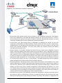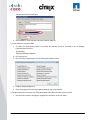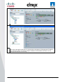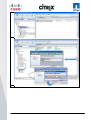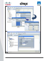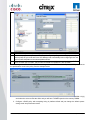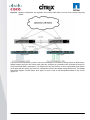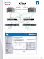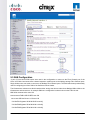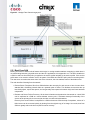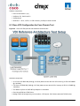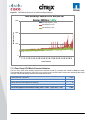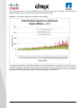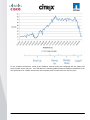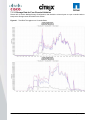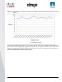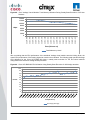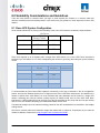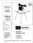
1
Reference Architecture-Based Design Citrix XenDesktop Built on FlexPod Citrix XenDesktop Using Citrix XenServer, Cisco Unified Computing System, Nexus 5000, and NetApp Storage Cisco Validated Design July 2011 Contents 1.0 Goal ........................................................................................................................................................ 5 1.1 Audience ............................................................................................................................................. 5 1.2 Objectives ........................................................................................................................................... 5 2.0 Summary of Main Findings .................................................................................................................. 6 3.0 Infrastructure Components .................................................................................................................. 7 3.1 Cisco Unified Computing System ....................................................................................................... 7 3.2 Cisco Unified Computing System Components.................................................................................. 8 3.2.1 Fabric Interconnect ...................................................................................................................... 8 3.2.2 Cisco UCS 2100 Series Fabric Extenders .................................................................................. 9 3.2.3 Cisco UCS Chassis ................................................................................................................... 10 3.2.4 Cisco UCS B200 M1 Blade Server ........................................................................................... 11 3.2.5 Cisco UCS B250 M1 Blade Server ........................................................................................... 11 3.2.6 Intel Xeon 5500 Series Processor ............................................................................................. 11 3.2.7 Intel Xeon 5600 Series Processor ............................................................................................. 12 3.2.8 Cisco UCS B200 M2 Blade Server ........................................................................................... 13 3.2.9 Cisco UCS B250 M2 Extended Memory Blade Server ............................................................. 13 3.2.10 Cisco UCS B440 M1 High-Performance Blade Server ........................................................... 14 3.2.11 Cisco UCS M71KR-Q QLogic Converged Network Adapter ................................................... 14 3.2.12 Cisco Extended Memory Architecture ..................................................................................... 15 3.2.13 Cisco UCS C-Series Rack-Mount Servers .............................................................................. 16 3.3 Citrix XenDesktop ............................................................................................................................. 17 3.3.1 Citrix FlexCast Technology ....................................................................................................... 17 3.3.2 Citrix XenServer ........................................................................................................................ 17 3.3.3 High-Definition User Experience (HDX)Technology ................................................................. 18 3.3.4 Citrix XenDesktop Architecture Overview ................................................................................. 18 3.3.5 Citrix XenDesktop Hosted VDI Overview .................................................................................. 18 3.3.5 Citrix XenDesktop Hosted Shared Desktops Overview ............................................................ 22 3.3.6 Citrix XenDesktop Hosted Shared Desktops ............................................................................ 24 3.3.7 Citrix XenApp Virtual Applications ............................................................................................. 25 3.3.8 General Citrix XD Advantages and Value Proposition .............................................................. 25 3.4 NetApp Storage Solution and Components ...................................................................................... 27 3.4.1 Single Scalable Unified Architecture ......................................................................................... 27 3.4.2 Storage Efficiency ..................................................................................................................... 27 3.4.3 Thin Provisioning ....................................................................................................................... 28 3.4.4 NetApp Deduplication ................................................................................................................ 29 3.4.5 Performance .............................................................................................................................. 30 3.4.6 Transparent Storage Cache Sharing ........................................................................................ 30 3.4.7 NetApp Flash Cache and PAM ................................................................................................. 31 3.4.8 NetApp Write Optimization ........................................................................................................ 31 3.4.9 Flexible Volumes and Aggregates............................................................................................. 31 3.4.10 Operational Agility ................................................................................................................... 31 3.4.11 NetApp Operations Manager................................................................................................... 32 3.4.12 Data Protection ........................................................................................................................ 33 3.4.12.1 RAID-DP .......................................................................................................................... 33 3.4.12.2 Backup and Recovery ...................................................................................................... 33 3.4.13 Storage Sizing Best Practices ................................................................................................. 34 3.4.13.1 Gather Essential Solution Requirements ......................................................................... 34 3.4.13.2 Performance-Based and Capacity-Based Storage Estimation Processes ...................... 35 3.4.13.3 Getting Recommendations on Storage System Physical and Logical Configuration ...... 35 3.4.14 Storage Architecture Best Practices ....................................................................................... 36 3.4.15 Storage System Configuration Best Practices ........................................................................ 36 3.4.16 Building a Resilient Storage Architecture ................................................................................ 36 3.4.17 Top Resiliency Practices ......................................................................................................... 37 3.4.18 Building a High-Performance Storage Architecture ................................................................ 37 © 2011 Cisco Systems, Inc. All rights reserved. This document is Cisco Public Information. Cisco Validated Design Page 2 3.5 FlexPod Technical Overview ............................................................................................................ 38 3.5.1 Audience.................................................................................................................................... 39 3.5.2 FlexPod Architecture ................................................................................................................. 39 3.5.3 FlexPod Market Overview ......................................................................................................... 40 3.5.3.1 The Challenge .................................................................................................................... 40 3.5.3.2 The Solution ....................................................................................................................... 40 3.5.3.3 NetApp: Unified Architecture for Extreme Efficiencies....................................................... 41 3.6 Cisco Networking Infrastructure ....................................................................................................... 41 3.6.1 Cisco Nexus 5548 28-Port Switch ............................................................................................. 41 3.6.2 Cisco Nexus 5500 Series Feature Highlights ............................................................................ 42 3.6.2.1 Features and Benefits ........................................................................................................ 42 3.6.2.2 10 Gigabit Ethernet and Unified Fabric Features .............................................................. 42 3.6.2.3 Low Latency ....................................................................................................................... 42 3.7 Microsoft Windows 7 ......................................................................................................................... 42 3.7.1 Microsoft Windows 7 Image Creation and Provisioning ............................................................ 43 3.7.1.1 Create Windows 7 Virtual Machine and Install Standard Software ................................... 44 3.7.1.2 Tuning Microsoft Windows 7 Image for VDI ...................................................................... 44 3.7.1.3 Provisioning Services (PVS) vDisk Creation ..................................................................... 45 3.7.1.4 Install and Configure Additional Software Components .................................................... 47 3.7.1.5 Add 3-GB Write Cache .VHD to vDisk Image .................................................................... 47 4.0 Architecture and Design of Citrix XenDesktops on Cisco Unified Computing System and NetApp Storage ....................................................................................................................................................... 50 4.1 Design Fundamentals ....................................................................................................................... 50 4.1.1 Hosted Shared Design Fundamentals ...................................................................................... 51 4.1.1.1 Citrix XenApp Policies ........................................................................................................ 51 4.1.1.2 Worker Groups ................................................................................................................... 51 4.1.1.3 Load Managed Groups ...................................................................................................... 51 4.1.2 Hosted VDI Design Fundamentals ............................................................................................ 51 4.1.2.1 Hypervisor Selection .......................................................................................................... 52 4.1.2.2 Provisioning Services ......................................................................................................... 52 4.1.3 Designing a Citrix XenDesktop Deployment ............................................................................. 53 5.0 Solution Validation .............................................................................................................................. 54 5.1 Configuration Topology for Scalability of Citrix XenDesktops on Cisco Unified System and NetApp Storage ................................................................................................................................................................ 54 5.2 Cisco Unified Computing System Configuration............................................................................... 56 5.2.1 QOS and COS in Cisco Unified Computing System ................................................................. 63 5.2.2 System Class Configuration ...................................................................................................... 63 5.2.3 Cisco UCS System Class Configuration ................................................................................... 63 5.3 Citrix XenDesktop Configuration ...................................................................................................... 66 5.3.1 Citrix XenDesktop Desktop Delivery Controller (DDC) ............................................................. 68 5.3.2 Farm Configuration .................................................................................................................... 68 5.3.3 Provisioning Services Configuration ......................................................................................... 68 5.3.4 Storage Configuration for the Citrix XenServer Hosting the Virtual Desktop Virtual Machine .. 69 5.3.5 Citrix Provisioning Services ....................................................................................................... 70 5.3.6 Citrix Provisioning Server (PVS) for use with Standard Desktops ............................................ 70 5.3.7 Hosted Shared Desktops Environment Configuration .............................................................. 73 5.4 LAN Configuration ............................................................................................................................ 74 5.5 SAN Configuration ............................................................................................................................ 77 5.5.1 Boot From SAN ......................................................................................................................... 79 5.5.2 Configuring Boot From SAN on the Cisco Unified Computing System ..................................... 80 5.5.3 SAN Configuration ..................................................................................................................... 85 5.5.4 Cisco UCS Manager Configuration ........................................................................................... 86 5.6 NetApp Storage Configuration .......................................................................................................... 88 5.6.1 Example of a NetApp NFS Volume Configuration .................................................................... 90 5.6.2 NetApp Deduplication in Practice .............................................................................................. 95 5.7 Citrix XenServer Configuration ..................................................................................................... 96 © 2011 Cisco Systems, Inc. All rights reserved. This document is Cisco Public Information. Cisco Validated Design Page 3 5.7.1 Cisco UCS Configuration for Citrix XenServer Installation ....................................................... 97 5.7.2 VLAN Configuration for XenServer Host Management Interfaces ............................................ 98 5.8 OS Installation .................................................................................................................................. 98 5.8.1 XenServer Networking ............................................................................................................ 100 5.9 XenServer Resource Pools ............................................................................................................ 101 6.0 Test Setup and Configurations ........................................................................................................ 104 6.1 Cisco UCS Test Configuration for Single-Server Scalability Test Setup ........................................ 104 6.2 Cisco UCS Configuration for Two-Chassis Test............................................................................. 105 6.3 Cisco UCS Configuration for Four-Chassis Test ............................................................................ 106 6.4 Testing Methodology ...................................................................................................................... 107 6.4.1 Load Generation ...................................................................................................................... 107 6.4.2 User Workload Simulation – Login VSI from Login Consultants ............................................. 107 6.4.3 Success Criteria ...................................................................................................................... 108 6.4.3.1 Login VSI Corrected Optimal Performance Index (COPI) ............................................... 108 6.4.3.2 Login VSI Max .................................................................................................................. 108 7.0 Test Results ....................................................................................................................................... 110 7.1 Citrix XenDesktop Hosted VDI Test Results .................................................................................. 110 7.1.1 Single Cisco UCS Blade Server Validation ............................................................................. 110 7.1.2 Two Cisco UCS Blade Chassis Validation .............................................................................. 111 7.1.3 Four Cisco UCS Blade Chassis Validation ............................................................................. 112 7.1.3.1 Storage Data for Four-Chassis Validation ............................................................................ 122 7.2 Citrix XenDesktop with XenApp Hosted Shared Test Results ....................................................... 125 8.0 Scalability Considerations and Guidelines .................................................................................... 130 8.1 Cisco UCS System Configuration ................................................................................................... 130 9.0 Acknowledgments ............................................................................................................................ 131 10.0 References ....................................................................................................................................... 132 APPENDIX A ............................................................................................................................................ 133 © 2011 Cisco Systems, Inc. All rights reserved. This document is Cisco Public Information. Cisco Validated Design Page 4 1.0 Goal The goal of this document is to provide architectural design and sizing guidelines for the hosting of small-to-large scale Citrix XenDesktop 4 and Citrix XenApp environments in a Cisco Data Center Fabric environment. This document presents one of a portfolio of design documents intended to simplify, ease and accelerate the deployment of Cisco VXI Desktop Virtualization Solutions. This specific document reports the results of a study evaluating the scalability of the Citrix XenDesktop environment on Cisco Unified Computing System™ (UCS) BSeries Blade Servers connected to NetApp Storage arrays. This document reflects the best practice recommendations and sizing guidelines for large-scale customer deployments of XenDesktops in FlexPod environments. 1.1 Audience This document is intended to assist solution architects, sales engineers, field engineers and consultants in planning, design, and deployment of Citrix XenDesktop hosted desktop virtualization solutions on the Cisco Unified Computing System. This document assumes that the reader has an architectural understanding of the Cisco Unified Computing System, Citrix desktop software, NetApp storage system, and related software. 1.2 Objectives This document is intended to articulate the design considerations and validation efforts required to design and deploy Citrix XenDesktops on the Cisco Unified Computing System with NetApp storage running in a virtualized environment on top of Citrix XenServer. The desktop virtualization hosting solution described in this paper forms a core building block of the Cisco Virtualization Experience Infrastructure (VXI) solution that delivers an end-to-end data center, network and end point solutions for desktop virtualization and voice and video communications. © 2011 Cisco Systems, Inc. All rights reserved. This document is Cisco Public Information. Cisco Validated Design Page 5 2.0 Summary of Main Findings The hosting of Citrix XenDesktop Hosted Virtual Desktops (VDI) and Hosted Shared Virtual Desktops models and FlexCast with Citrix XenServer Hypervisors on Cisco UCS B-Series Blade Servers and NetApp storage were successfully validated. The Cisco UCS B250 M2 Extended Memory Blade Servers offer an optimal memory configuration that allows virtual desktop hosting servers to use the full CPU capabilities of the servers. The 192 GB of memory allowed a high density of desktop sessions per Cisco UCS B250 M2 Extended Memory Blade Servers while offering 1.5 GB of memory to be allocated per desktop-based virtual machine. We were able to scale to 110 Microsoft Windows 7 desktops while running a knowledge worker load. The validated environment consisted of a completely virtualized infrastructure with virtual machines hosted by Citrix XenServer. All the virtual desktop and supporting infrastructure components including Active Directory, Citrix Provisioning Server, and the Citrix XenDesktop Desktop Delivery Controllers were hosted in a virtual machine environment on Citrix XenServer 5.6. The tested design showed linear scalability when expanding from 1 server to 16 servers. The performance testing showed that the same user desktop experience and response times were achieved with 110 desktops running on 1 server as with 1760 desktops running on 16 servers. The integrated management model and rapid provisioning capabilities of Cisco UCS Manager makes it easy for scaling the number of desktops from small pilots on a single UCS chassis to very large organization-wide deployments running on tens of chassis. The testing validates that the 10Gbps Unified Fabric provides a high performance; scalable infrastructure and offers deterministic performance with respect to user response times during the load and stress testing. The testing validates that the tested reference architecture can scale linearly from 1 chassis to 4 chassis and beyond without making any changes to the design or infrastructure components. This also requires the proper backend storage scaling as provided by NetApp storage. Desktop virtual machine ―Boot-up‖ or ―Logon‖ Storms (from rapid concurrent or simultaneous user logons) need to be considered in the server and storage design as they have largest substantial scalability impact on this solution as well as VDI environments in general. The reference architecture represented in this document was able to handle the additional stresses presented by the most extreme boot-up and log-on storm conditions. © 2011 Cisco Systems, Inc. All rights reserved. This document is Cisco Public Information. Cisco Validated Design Page 6 3.0 Infrastructure Components The following sections detail the infrastructure components used in this configuration. 3.1 Cisco Unified Computing System The Cisco Unified Computing System is a next-generation data center platform that unites compute, network, storage access, and virtualization into a cohesive system designed to reduce total cost of ownership (TCO) and increase business agility. The Cisco Unified Computing System server portfolio consists of the Blade Server platform, B-Series and the C-Series Rack Mount platform. We chose the Cisco UCS B-Series Blade Server platform for this study. The system integrates a low-latency, lossless 10 Gigabit Ethernet unified network fabric with enterprise-class, x86-architecture servers. The system is an integrated, scalable, multi-chassis platform in which all resources participate in a unified management domain. The main system components include: Compute—the system is based on an entirely new class of computing system that incorporates blade servers based on Intel Xeon 5500 Series Processors. The Cisco UCS blade servers offer patented Cisco Extended Memory Technology to support applications with large datasets and allow more virtual machines per server. Network—the system is integrated onto a low-latency, lossless, 10-Gbps unified network fabric. This network foundation consolidates what today are three separate networks: LANs, SANs, and high-performance computing networks. The unified fabric lowers costs by reducing the number of network adapters, switches, and cables, and by decreasing power and cooling requirements. Virtualization—the system unleashes the full potential of virtualization by enhancing the scalability, performance, and operational control of virtual environments. Cisco security, policy enforcement, and diagnostic features are now extended into virtualized environments to better support changing business and IT requirements. Storage access—the system provides consolidated access to both SAN storage and Network Attached Storage (NAS) over the unified fabric. Unifying storage access means that the Cisco Unified Computing System can access storage over Ethernet, Fibre Channel, Fibre Channel over Ethernet (FCoE), and iSCSI, providing customers with choice and investment protection. In addition, administrators can pre-assign storage-access policies for system connectivity to storage resources, simplifying storage connectivity and management while helping increase productivity. Management—the system uniquely integrates all the system components, enabling the entire solution to be managed as a single entity through the Cisco UCS Manager software. The Cisco UCS Manager provides an intuitive graphical user interface (GUI), a command-line interface (CLI), and a robust application programming interface (API) to manage all system configuration and operations. The Cisco UCS Manager helps increase IT staff productivity, enabling storage, network, and server administrators to collaborate on defining service profiles for applications. Service profiles are logical representations of desired physical configurations and infrastructure policies. They help automate provisioning and increase business agility, allowing data center managers to provision resources in minutes instead of days. Working as a single, cohesive system, these components unify technology in the data center. They represent a radical simplification in comparison to traditional systems, helping simplify data center operations while reducing power and cooling requirements. The system amplifies IT agility for improved business outcomes. The Cisco Unified Computing System components illustrated in Figure 1 include, from left to right, fabric interconnects, blade server chassis, blade servers, and in the foreground, fabric extenders and network adapters. © 2011 Cisco Systems, Inc. All rights reserved. This document is Cisco Public Information. Cisco Validated Design Page 7 Figure 1. Cisco Unified Computing System 3.2 Cisco Unified Computing System Components 3.2.1 Fabric Interconnect The Cisco UCS 6100 Series Fabric Interconnects are a core part of the Cisco Unified Computing System, providing both network connectivity and management capabilities for the system (Figure 2). The Cisco UCS 6100 Series offers line-rate, low-latency, lossless 10 Gigabit Ethernet and FCoE functions. The Cisco UCS 6100 Series provides the management and communication backbone for the Cisco UCS B-Series Blade Servers and Cisco UCS 5100 Series Blade Server Chassis. All chassis, and therefore all blades, attached to the Cisco UCS 6100 Series Fabric Interconnects become part of a single, highly available management domain. In addition, by supporting unified fabric, the Cisco UCS 6100 Series provides both the LAN and SAN connectivity for all blades within its domain. From a networking perspective, the Cisco UCS 6100 Series uses a cut-through architecture, supporting deterministic, low-latency, line-rate 10 Gigabit Ethernet on all ports, independent of packet size and enabled services. The product family supports Cisco low-latency, lossless 10 Gigabit Ethernet unified network fabric capabilities, which increase the reliability, efficiency, and scalability of Ethernet networks. The fabric interconnect supports multiple traffic classes over a lossless Ethernet fabric from the blade through the interconnect. Significant TCO savings come from an FCoE-optimized server design in which network interface cards (NICs), host bus adapters (HBAs), cables, and switches can be consolidated. The Cisco UCS 6100 Series is also built to consolidate LAN and SAN traffic onto a single unified fabric, saving the capital and operating expenses associated with multiple parallel networks, different types of adapter cards, switching infrastructure, and cabling within racks. Fibre Channel expansion modules in the interconnect support direct connections from the Cisco Unified Computing System to existing native Fibre Channel SANs. The capability to connect FCoE to native Fibre Channel protects existing storage system investments while dramatically simplifying in-rack cabling. Figure 2. Cisco UCS 6120XP 20-Port Fabric Interconnect (Top) and Cisco UCS 6140XP 40-Port Fabric Interconnect © 2011 Cisco Systems, Inc. All rights reserved. This document is Cisco Public Information. Cisco Validated Design Page 8 The Cisco UCS 6100 Series is equipped to support the following module options: ● Ethernet module that provides 6 ports of 10 Gigabit Ethernet using the SFP+ interface ● Fibre Channel plus Ethernet module that provides 4 ports of 10 Gigabit Ethernet using the SFP+ interface; and 4 ports of 1/2/4-Gbps native Fibre Channel connectivity using the SFP interface ● Fibre Channel module that provides 8 ports of 1/2/4-Gbps native Fibre Channel using the SFP interface for transparent connectivity with existing Fibre Channel networks ● Fibre Channel module that provides 6 ports of 1/2/4/8-Gbps native Fibre Channel using the SFP or SFP+ interface for transparent connectivity with existing Fibre Channel networks Figure 3. From left to right: 8-Port 1/2/4-Gbps Native Fibre Channel Expansion Module; 4-Port Fibre Channel plus 4-Port 10 3.2.2 Cisco UCS 2100 Series Fabric Extenders The Cisco UCS 2100 Series Fabric Extenders bring the unified fabric into the blade server enclosure, providing 10 Gigabit Ethernet connections between blade servers and the fabric interconnect, simplifying diagnostics, cabling, and management. The Cisco UCS 2100 Series extends the I/O fabric between the Cisco UCS 6100 Series Fabric Interconnects and the Cisco UCS 5100 Series Blade Server Chassis, enabling a lossless and deterministic FCoE fabric to connect all blades and chassis together. Since the fabric extender is similar to a distributed line card, it does not do any switching and is managed as an extension of the fabric interconnects. This approach removes switching from the chassis, reducing overall infrastructure complexity and enabling the Cisco Unified Computing System to scale to many chassis without multiplying the number of switches needed, reducing TCO and allowing all chassis to be managed as a single, highly available management domain. The Cisco 2100 Series also manages the chassis environment (the power supply and fans as well as the blades) in conjunction with the fabric interconnect. Therefore, separate chassis management modules are not required. The Cisco UCS 2100 Series Fabric Extenders fit into the back of the Cisco UCS 5100 Series chassis. Each Cisco UCS 5100 Series chassis can support up to two fabric extenders, enabling increased capacity as well as redundancy. © 2011 Cisco Systems, Inc. All rights reserved. This document is Cisco Public Information. Cisco Validated Design Page 9 Figure 4. Rear view of Cisco UCS 5108 Blade Server Chassis with two Cisco UCS 2104XP Fabric Extenders The Cisco UCS 2104XP Fabric Extender has four 10 Gigabit Ethernet, FCoE-capable, Small Form-Factor Pluggable Plus (SFP+) ports that connect the blade chassis to the fabric interconnect. Each Cisco UCS 2104XP has eight 10 Gigabit Ethernet ports connected through the midplane to each half-width slot in the chassis. Typically configured in pairs for redundancy, two fabric extenders provide up to 80 Gbps of I/O to the chassis. Figure 5. Cisco UCS 2104XP Fabric Extender 3.2.3 Cisco UCS Chassis The Cisco UCS 5100 Series Blade Server Chassis is a crucial building block of the Cisco Unified Computing System, delivering a scalable and flexible blade server chassis for today's and tomorrow's data center while helping reduce TCO. Cisco's first blade server chassis offering, the Cisco UCS 5108 Blade Server Chassis, is six rack units (6RU) high and can mount in an industry-standard 19-inch rack. A chassis can house up to eight half-width Cisco UCS BSeries Blade Servers and can accommodate both half- and full-width blade form factors. Four single-phase, hot-swappable power supplies are accessible from the front of the chassis. These power supplies are 92 percent efficient and can be configured to support non-redundant, N+ 1 redundant and gridredundant configuration. The rear of the chassis contains eight hot-swappable fans, four power connectors (one per power supply), and two I/O bays for Cisco UCS 2104XP Fabric Extenders. A passive mid-plane provides up to 20 Gbps of I/O bandwidth per server slot and up to 40 Gbps of I/O bandwidth for two slots. The chassis is capable of supporting future 40 Gigabit Ethernet standards. Figure 6. Cisco Blade Server Chassis (front and back view) © 2011 Cisco Systems, Inc. All rights reserved. This document is Cisco Public Information. Cisco Validated Design Page 10 3.2.4 Cisco UCS B200 M1 Blade Server The Cisco UCS B200 M1 Blade Server is a half-width, two-socket blade server. The system uses two Intel Xeon 5500 Series Processors, up to 96 GB of DDR3 memory, two optional hot-swappable small form factor (SFF) serial attached SCSI (SAS) disk drives, and a single mezzanine connector for up to 20 Gbps of I/O throughput. The server balances simplicity, performance, and density for production-level virtualization and other mainstream data center workloads. Figure 7. Cisco UCS B200 M1 Blade Server 3.2.5 Cisco UCS B250 M1 Blade Server The Cisco UCS B250 M1 Extended Memory Blade Server is a full-width, two-socket blade server featuring Cisco Extended Memory Technology. The system supports two Intel Xeon 5500 Series processors, up to 384 GB of DDR3 memory, two optional SFF SAS disk drives, and two mezzanine connections for up to 40 Gbps of I/O throughput. The server increases performance and capacity for demanding virtualization and large-data-set workloads with greater memory capacity and throughput. Figure 8. Cisco UCS B250 M1 Extended Memory Blade Server 3.2.6 Intel Xeon 5500 Series Processor With innovative technologies that boost performance, energy efficiency, and virtualization flexibility, two-processor platforms based on the Intel Xeon 5500 Series Processor make it easier to deliver more business services within existing data center facilities. Data center efficiency starts at the core – with energy-efficient processors and features that help you get the most out of each rack. With a unique combination of performance and energyefficiency features plus flexible virtualization, the Intel Xeon 5500 Series Processor offers an effective antidote to data center sprawl and improves business competitiveness. The combination of Intel Turbo Boost Technology and Intel Hyper-Threading Technology delivers optimal performance for each enterprise application, and Intel QuickPath Technology dramatically increases application performance and throughput for bandwidth-intensive applications. Greater per-server performance means that you can do more with fewer servers and potentially save significantly on operating costs. Intel Intelligent Power Technology works alongside these new performance features to deliver better performance with lower power consumption at all operating points, achieving the best available performance/watt. High-performance 95-watt, standard 80-watt and low-power 60-watt versions enable highdensity deployments in both rack and blade form factors. Intel VT with Intel FlexMigration and Intel FlexPriority also gives IT more choice in managing and allocating virtualized workloads across new and existing platforms. Intel Turbo Boost Technology plus hardware assists from Intel VT improves performance for applications running in virtual machines. Intel VT FlexMigration, in combination with virtualization management software, can help IT to conserve power, rebalance workloads and reduce energy consumption. © 2011 Cisco Systems, Inc. All rights reserved. This document is Cisco Public Information. Cisco Validated Design Page 11 Figure 9. Intel Xeon 5500 Series Processor 3.2.7 Intel Xeon 5600 Series Processor As data centers reach the upper limits of their power and cooling capacity, efficiency has become the focus of extending the life of existing data centers and designing new ones. As part of these efforts, IT needs to refresh existing infrastructure with standard enterprise servers that deliver more performance and scalability, more efficiently. The Intel Xeon 5600 Series Processor automatically regulates power consumption and intelligently adjusts server performance according to your application needs, both energy efficiency and performance. The secret to this compelling combination is Intel‘s new 32nm Xeon microarchitecture. Featuring Intel Intelligent Power Technology that automatically shifts the CPU and memory into the lowest available power state, while delivering the performance you need, the Intel Xeon 5600 Series Processor with Intel Micro-architecture Xeon delivers the same performance as previous-generation servers but uses up to 30 percent less power. You can achieve up to a 93 percent reduction in energy costs when consolidating your single-core infrastructure with a new infrastructure built on Intel Xeon 5600 Series Processor. This groundbreaking intelligent server technology features: ● Intel‘s new 32nm Microarchitecture Xeon built with second-generation high-k and metal gate transistor technology. ● Intelligent Performance that automatically optimizes performance to fit business and application requirements and delivers up to 60 percent more performance per watt than Intel Xeon 5500 Series Processor. ● Automated Energy Efficiency that scales energy usage to the workload to achieve optimal performance/watt and with new 40 Watt options and lower power DDR3 memory, you can lower your energy costs even further. ● Flexible virtualization that offers best-in-class performance and manageability in virtualized environments to improve IT infrastructure and enable up to 15:1 consolidation over two socket, single-core servers. New standard enterprise servers and workstations built with this new generation of Intel process technology © 2011 Cisco Systems, Inc. All rights reserved. This document is Cisco Public Information. Cisco Validated Design Page 12 offer an unprecedented opportunity to dramatically advance the efficiency of IT infrastructure and provide unmatched business capabilities. Figure 10. Intel Xeon 5600 Series Processor 3.2.8 Cisco UCS B200 M2 Blade Server The Cisco UCS B200 M2 Blade Server is a half-width, two-socket blade server. The system uses two Intel Xeon 5600 Series Processors, up to 96 GB of DDR3 memory, two optional hot-swappable small form factor (SFF) serial attached SCSI (SAS) disk drives, and a single mezzanine connector for up to 20 Gbps of I/O throughput. The server balances simplicity, performance, and density for production-level virtualization and other mainstream data center workloads. Figure 11. Cisco UCS B200 M2 Blade Server 3.2.9 Cisco UCS B250 M2 Extended Memory Blade Server The Cisco UCS B250 M2 Extended Memory Blade Server is a full-width, two-socket blade server featuring Cisco Extended Memory Technology. The system supports two Intel Xeon 5600 Series Processors, up to 384 GB of DDR3 memory, two optional SFF SAS disk drives, and two mezzanine connections for up to 40 Gbps of I/O throughput. The server increases performance and capacity for demanding virtualization and large-data-set workloads with greater memory capacity and throughput. © 2011 Cisco Systems, Inc. All rights reserved. This document is Cisco Public Information. Cisco Validated Design Page 13 Figure 12. Cisco UCS B250 M2 Extended Memory Blade Server 3.2.10 Cisco UCS B440 M1 High-Performance Blade Server The Cisco UCS B440 M1 High-Performance Blade Server is a full-width, 4-socket system. Two or four Intel Xeon 7500 Series Processors with intelligent performance that automatically adapts to the diverse needs of a virtualized environment and offers advanced reliability for mission-critical workloads. It supports 32 dual in-line memory module (DIMM) slots and up to 256 GB at 1333 MHz based on Samsung's 40 nanometer class (DDR3) technology. There is four optional front-accessible, hot-swappable Small Form-Factor Pluggable (SFFP) drives and an LSI SAS2108 RAID Controller. The Cisco UCS B440 M1 blade server can accommodate two dual-port mezzanine cards for up to 40 Gbps I/O per blade. Options include a Cisco UCS M81KR Virtual Interface Card (VIC) or converged network adapter (Emulex or QLogic compatible). Figure 13. Cisco UCS B440 M1 Blade Server 3.2.11 Cisco UCS M71KR-Q QLogic Converged Network Adapter The Cisco UCS M71KR-Q QLogic Converged Network Adapter (CNA) is a QLogic-based FCoE mezzanine card that provides connectivity for Cisco UCS B-Series Blade Servers in the Cisco Unified Computing System. Designed specifically for the Cisco UCS blade servers, the adapter provides a dual-port connection to the midplane of the blade server chassis. The Cisco UCS M71KR-Q uses an Intel 82598 10 Gigabit Ethernet controller for network traffic and a QLogic 4-Gbps Fibre Channel controller for Fibre Channel traffic, all on the same mezzanine card. The Cisco UCS M71KR-Q presents two discrete Fibre Channel host bus adapter (HBA) ports and two Ethernet network ports to the operating system. Figure 14. Cisco USC M71KR-Q Network Adapter © 2011 Cisco Systems, Inc. All rights reserved. This document is Cisco Public Information. Cisco Validated Design Page 14 The Cisco UCS M71KR-Q provides both 10 Gigabit Ethernet and 4-Gbps Fibre Channel functions using drivers from QLogic, providing: ● Risk mitigation through compatibility with current QLogic adapter-based SAN environments and drivers ● Reduced TCO through consolidation of LAN and SAN traffic over the same mezzanine card and fabric, reducing the overall number of network interface cards (NICs), HBAs, cables, and switches ● Integrated management with Cisco UCS Manager Figure 15. Cisco UCS M71KR-Q Architecture 3.2.12 Cisco Extended Memory Architecture Modern CPUs with built-in memory controllers support a limited number of memory channels and slots per CPU. The need for virtualization software to run multiple OS instances demands large amounts of memory, and that, combined with the fact that CPU performance is outstripping memory performance, can lead to memory bottlenecks. Even some traditional non-virtualized applications demand large amounts of main memory: database management system performance can be improved dramatically by caching database tables in memory, and modeling and simulation software can benefit from caching more of the problem state in memory. To obtain a larger memory footprint, most IT organizations are forced to upgrade to larger, more expensive, foursocket servers. CPUs that can support four-socket configurations are typically more expensive, require more power, and entail higher licensing costs. Cisco Extended Memory Technology expands the capabilities of CPUbased memory controllers by logically changing the geometry of main memory while still using standard DDR3 memory. This technology makes every four DIMM slots in the expanded memory blade server appear to the CPU‘s memory controller as a single DIMM that is four times the size (Figure 16). For example, using standard DDR3 DIMMs, the technology makes four 8-GB DIMMS appear as a single 32-GB DIMM. This patented technology allows the CPU to access more industry-standard memory than ever before in a twosocket server: ● For memory-intensive environments, data centers can better balance the ratio of CPU power to memory and install larger amounts of memory without having the expense and energy waste of moving to foursocket servers simply to have a larger memory capacity. With a larger main-memory footprint, CPU © 2011 Cisco Systems, Inc. All rights reserved. This document is Cisco Public Information. Cisco Validated Design Page 15 utilization can improve because of fewer disk waits on page-in and other I/O operations, making more effective use of capital investments and more conservative use of energy. ● For environments that need significant amounts of main memory but which do not need a full 384 GB, smaller-sized DIMMs can be used in place of 8-GB DIMMs, with resulting cost savings: two 4-GB DIMMS are typically less expensive than one 8-GB DIMM. Figure 16. Cisco Extended Memory Architecture 3.2.13 Cisco UCS C-Series Rack-Mount Servers The Cisco UCS C-Series Rack-Mount Servers (Figure 17) extend the Cisco Unified Computing System innovations to a rack-mount form factor, including a standards-based unified network fabric, Cisco VN-Link virtualization support, and Cisco Extended Memory Technology. Designed to operate both in standalone environments and as part of the Cisco Unified Computing System, these servers enable organizations to deploy systems incrementally—using as many or as few servers as needed—on a schedule that best meets the organization‘s timing and budget. Cisco UCS C-Series servers offer investment protection through the capability to deploy them either as standalone servers in heterogeneous data centers or as part of the Cisco Unified Computing System. Although this study was carried out on the Cisco UCS B-Series Blade Servers, the C-Series Rack-Mount Servers extend the same benefits to customers. Future desktop virtualization studies are planned on this server platform. Figure 17. Cisco UCS C-Series Rack-Mount Servers © 2011 Cisco Systems, Inc. All rights reserved. This document is Cisco Public Information. Cisco Validated Design Page 16 3.3 Citrix XenDesktop Citrix XenDesktop is a desktop virtualization solution that delivers Windows desktops as an on-demand service to any user, anywhere. With FlexCast™ delivery technology, XenDesktop can quickly and securely deliver individual applications or complete desktops to the entire enterprise, whether they are task workers, knowledge workers or mobile workers. Users now have the flexibility to access their desktop on any device, anytime, with a highdefinition user experience. With XenDesktop, IT can manage single instances of each OS, application and user profile and dynamically assemble them to increase business agility and greatly simplify desktop management. XenDesktop‘s open architecture enables customers to easily adopt desktop virtualization using any hypervisor, storage or management infrastructure. 3.3.1 Citrix FlexCast Technology XenDesktop FlexCast is an intelligent delivery technology that recognizes the user, device, and network, and delivers the correct virtual desktop and applications specifically tailored to meet the performance, security, and flexibility requirements of the user scenario. FlexCast for Desktops delivers any type of virtual desktop to any device—and can change this mix at any time. FlexCast for Apps delivers any type of virtual applications to any device. The FlexCast delivery technologies can be broken down into the following categories: ● Hosted shared desktops provide a locked-down, streamlined and standardized environment with a core set of applications, ideally suited for task workers where personalization is not required—or appropriate. ● Hosted virtual machine–based desktops (VDI) offer a personalized Windows desktop experience for office workers that can be securely delivered over any network to any device. ● Streamed VHD Desktops use the local processing power of rich clients, while providing centralized singleimage management of the desktop. These types of desktops are often used in computer labs and training facilities, and when users require local processing for certain applications or peripherals, ● Local virtual machine desktops extend the benefits of virtual desktops to mobile workers who need to use their laptops offline. ● FlexCast for Apps allows any Microsoft Windows application to be centralized and managed in the datacenter, hosted either on multi-user terminal servers or virtual machines, and instantly delivered as a service to physical and virtual desktops. Optimized for each user device, network and location, applications are delivered through a high-speed protocol for use while connected or streamed through Citrix application virtualization or Microsoft App-V directly to the endpoint for use when offline. A complete overview of the FlexCast technology can be found on Citrix.com, but for the purposes of the testing and validation represented in this paper only the Hosted VDI and Hosted Shared models were validated on the Cisco UCS hardware in conjunction with NetApp storage solutions. The Hosted Shared and Hosted VDI models provide a low-cost virtual desktop delivery solution that uses the power of existing PC resources to help customers get started with desktop virtualization. 3.3.2 Citrix XenServer In addition to the virtual desktop delivery options available with FlexCast, XenDesktop was intentionally designed to be hypervisor agnostic and therefore provide a choice when selecting a hypervisor to host virtual machinebased desktops. The open architecture of XenDesktop can utilize Citrix XenServer, Microsoft Hyper-V, and VMware vSphere hypervisors for the hosting virtual desktop infrastructure. For the purposes of the testing and validation represented in this paper only the Citrix XenServer bare-metal hypervisor was utilized to host virtual desktops. Citrix XenServer is an enterprise-ready, cloud-proven virtualization platform with all the capabilities needed to create and manage a virtual infrastructure at half the cost of other solutions. Organizations of any size can install the free XenServer in less than ten minutes to virtualize even the most demanding workloads and automate management processes, which increases IT flexibility and agility, and lowers costs. To add a rich set of © 2011 Cisco Systems, Inc. All rights reserved. This document is Cisco Public Information. Cisco Validated Design Page 17 management and automation capabilities designed to help customers create a virtual computing center, simply upgrade to one of the enhanced versions of XenServer. 3.3.3 High-Definition User Experience (HDX)Technology Citrix has been perfecting the virtual application delivery technology for more than two decades. These HighDefinition User Experience (HDX) technologies include software and hardware products, an advanced delivery protocol and intelligent algorithms used to optimize end-to-end system performance. Citrix XenDesktop incorporates the HDX technology to provide the most complete solution for high definition desktop and application virtualization on any device over any network. Citrix HDX is the only viable solution on the market for providing high definition multimedia content and graphics-intensive applications over the WAN, allowing businesses to utilize employee talent in more geographies while protecting intellectual property within the datacenter. HDX technology provides network and performance optimizations to deliver the best user experience over any network, including low bandwidth and high latency WAN connections. These user experience enhancements balance performance with low bandwidth–anything else becomes impractical to use and scale. 3.3.4 Citrix XenDesktop Architecture Overview The Citrix XenDesktop Hosted Shared and Hosted VDI FlexCast Delivery Technologies can deliver different types of virtual desktops based on the performance, security and flexibility requirements of each individual user. Although the two desktop delivery models use similar components, the over architecture is distinctly different. 3.3.5 Citrix XenDesktop Hosted VDI Overview Hosted VDI uses a hypervisor to host all the desktops in the data center. Hosted VDI desktops can either be pooled or assigned. Pooled virtual desktops use Citrix Provisioning Services to stream a standard desktop image to each desktop instance upon boot-up therefore the desktop is always reverted back to its clean, original state. Citrix Provisioning Services enables you to stream a single desktop image to create multiple virtual desktops on one or more hypervisors in a data center. This feature greatly reduces the amount of storage required compared to other methods of creating virtual desktops. The high-level components of a Citrix XenDesktop architecture utilizing the Hosted VDI model for desktop delivery are shown in Figure 18: © 2011 Cisco Systems, Inc. All rights reserved. This document is Cisco Public Information. Cisco Validated Design Page 18 Figure 18. Citrix XenDesktop on XenServer Architecture ● Web Interface: Web Interface provides the user interface to the XenDesktop environment. Web Interface brokers user authentication, enumerates the available desktops and, upon launch, delivers an .ica file to the Citrix Receiver on the user‘s local device to initiate a connection. Because Web Interface is a critical component, redundant servers must be available to provide fault tolerance. ● License Server: The Citrix License Server is responsible for managing the licenses for all of the components of XenDesktop 4 including XenServer 5.6 (Only XenServer 5.6 can use the License Server). XenDesktop has a 90 day grace period which allows the system to function normally for 90 days if the license server becomes unavailable. This grace period offsets the complexity involved with building redundancy into the license server. ● Domain Controller: The Domain Controller hosts Active Directory, Dynamic Host Configuration Protocol (DHCP) and Domain Name System (DNS). Active Directory provides a common namespace and secure method of communication between all the servers and desktops in the environment. DNS provides IP Host name resolution for the core XenDesktop infrastructure components. DHCP is used by the virtual desktop to request and obtain an IP address from the DHCP service. DHCP uses Option 66 and 67 to specify the bootstrap file location and filename to a virtual desktop. The DHCP service receives requests on UDP port 67 and sends data to UDP port 68 on a virtual desktop. The virtual desktops then have the operating system streamed over the network utilizing Citrix Provisioning Services. ● Provisioning Services: Provisioning Services (PVS) creates and provisions virtual desktops from a single desktop image (vDisk) on demand, optimizing storage utilization and providing a pristine virtual desktop to each user every time they log on. Desktop provisioning also simplifies desktop images, provides the best flexibility, and offers fewer points of desktop management for both applications and desktops. The Trivial File Transfer Protocol (TFTP) and Pre-boot eXecution Environment (PXE) services are required for the virtual desktop to boot off the network and download the bootstrap file which instructs the virtual desktop to connect to the PVS server for registration and vDisk access instructions. ● Desktop Delivery Controller: The XenDesktop controllers are responsible for maintaining the proper level of idle desktops to allow for instantaneous connections, monitoring the state of online and connected virtual desktops and shutting down virtual desktops as needed. The primary XD controller is configured as the © 2011 Cisco Systems, Inc. All rights reserved. This document is Cisco Public Information. Cisco Validated Design Page 19 farm master server. The farm master is able to focus on its role of managing the farm when an additional XenDesktop Controller acts as a dedicated XML server. The XML server is responsible for user authentication, resource enumeration and desktop launching process. A failure in the XML broker service will result in users being unable to start their desktops. It is for this reason why it is recommended to have multiple Controllers per farm ● Data Store: Each XenDesktop farm requires a database called the data store. Citrix XenDesktops uses the data store to centralize configuration information for a farm in one location. The data store maintains all the static information about the XenDesktop environment. ● Virtual Desktop Agent: The Virtual Desktop Agent (VDA) is installed on the virtual desktops and enables direct ICA (Independent Computing Architecture) connections between the virtual desktop and user devices with the Citrix online plug-in ● Citrix Online Plug-in: Installed on user devices, the Citrix online plug-in enables direct ICA connections from user devices to virtual desktops. The plug-in software is available for a range of different devices so users can connect to published applications from various platforms. You can deploy and update the online plug-in using Citrix Receiver. ● Citrix XenServer: XenServer is an enterprise-class virtual machine infrastructure solution that creates the foundation for delivering virtual desktops and offers advanced management features. Multiple virtual machines can run on XenServer, which takes advantage of the advanced virtualization features of the latest virtualization-enabled processors from Intel and AMD. ● Citrix XenApp: Citrix XenApp is an on-demand application delivery solution that enables any Windows application to be virtualized, centralized, and managed in the datacenter, and instantly delivered as a service to users anywhere on any device. XenApp can be used to deliver both virtualized applications and virtualized desktops. In the Hosted VDImodel, XenApp is typically used for application virtualization. All the aforementioned components interact to provide a virtual desktop to an end-user based on the FlexCast Hosted VDI desktop delivery model using the Provisioning Services feature of XenDesktop. This architecture provides the end-user with a pristine desktop at each logon based on a centralized desktop image that is owned and managed by IT. The following steps outline the sequence of operations executed by XenDesktop to deliver a Hosted VDI virtual desktop to the end user. © 2011 Cisco Systems, Inc. All rights reserved. This document is Cisco Public Information. Cisco Validated Design Page 20 Figure 19. Operational Sequence 1. The end user launches an internet browser to access Web Interface. 2. Web Interfaces prompts the user for Active Directory credentials and passes the credentials to the Desktop Delivery Controller acting as a dedicated XML server. 3. The XML Service running the dedicated XML server (Desktop Delivery Controller) authenticates the user against Active Directory. 4. After the user is successfully authenticated, the XML Service contacts the Data Store to determine which virtual desktops are available for that user. 5. The virtual desktop information is sent back to Web Interface and Web Interface renders a web page containing a list of available desktops. 6. The user clicks on the desktop icon and Web Interface forwards the request to the Desktop Delivery Controller. If the virtual desktop is powered on, the Desktop Delivery Controller will tell the Virtual Desktop Agent running on the virtual machine to start listening for an incoming session. If the virtual desktop is not powered on, the Desktop Delivery Controller will tell the XenServer to start a new virtual desktop and then notify the Virtual Desktop Agent. a. In a Hosted VDI configuration with Provisioning Services, the virtual desktop boots through the network PXE boot. The virtual desktop contacts the DHCP server to find an IP address and the location of the boot file. The boot file comes from Provisioning Services and provides instructions for accessing the centralized desktop image. b. After the virtual desktop receives the boot file with instructions, it contacts the Provisioning Server and provides its MAC address. Provisioning Server identifies the correct virtual desktop disk based on the MAC address and sends portions of the virtual disk to the virtual desktop required to start-up the machine. 7. The virtual desktop connection information is forwarded onto Web Interface. Web Interface creates a launch file (ICA) for the specific virtual desktop and forwards the launch file to the end user‘s device. 8. The Virtual Desktop Agent running on the virtual desktop tells the Desktop Delivery Controller that the user has connected. The user‘s logon information is then sent for validation. © 2011 Cisco Systems, Inc. All rights reserved. This document is Cisco Public Information. Cisco Validated Design Page 21 9. The Desktop Delivery Controller validates the login credentials and checks out a license from the Citrix License Server. If the credentials are valid and a license is available, then the credentials, XenDesktop license and policies are sent to the virtual desktop for processing. 10. Once the connection has been approved, the Virtual Desktop Agent uses the transferred credentials to logon against Active Directory and applies profile configurations. 3.3.5 Citrix XenDesktop Hosted Shared Desktops Overview Hosted Shared desktops use the XenApp feature of XenDestkop to deliver session-based desktops. The Hosted Shared model is built on Microsoft Remote Desktop Services (formerly Terminal Services) platform and end users effectively share one configuration of a Windows Server desktop through independent sessions. The high-level components of the Citrix XenApp feature of XenDesktop architecture for both the Hosted Shared model for desktop delivery and the traditional XenApp model of virtual application delivery are shown in Figure 20. Figure 20. Citrix XenApp Architecture Citrix XenApp Farm Citrix License Server Citrix XenApp Servers Core Business Applications Load Managed Group Backup Data Collector Application Hub Web Interface Citrix XenApp Servers Line-of-Business Load Managed Group Primary Data Collector Data Store Citrix XenApp Servers Hosted Shared Desktops ● Web Interface: Web Interface provides the user interface for virtual applications and desktops. Web Interface brokers user authentication, enumerates the available desktops and applications. Then upon application or desktop launch, delivers an .ica file to the Citrix Receiver on the user‘s local device to initiate a connection. Because Web Interface is a critical component, redundant servers must be available to provide fault tolerance. ● Data Collector: The data collector is responsible for authenticating users, identifying accessible desktops or applications, and identifying which XenApp server a user should connect. The data collector is the brokering mechanism for requests coming from the end user and Web Interface destined to the XenApp farm. As the size of the XenApp farm increase, the data collector moves from becoming a shared server, © 2011 Cisco Systems, Inc. All rights reserved. This document is Cisco Public Information. Cisco Validated Design Page 22 responsible for delivering desktops or applications, to a dedicated server. If the primary data collector were to fail, a backup, with the same hardware and software configuration, should also be available. Similar to Web Interface, providing fault tolerance to the Data Collector servers is recommended. ◦ ● Data Collector (Dedicated XML Server): A Data Collector acting as a dedicated XML server allows the master Data Collector to focus on farm management while directing the Web Interface servers to communicate with the XML servers. The XML broker is responsible for user authentication, resource enumeration and resource launching processes. A failure in the XML broker service will result in users being unable to start their desktop. Due to its criticality it is best to have at least two dedicated XML servers. Load Managed Groups: Whether delivering applications or desktops, organizations might create load managed groups based on business requirements. Load managed groups are created to focus a set of XenApp servers on a particular set of applications or desktops. This is done for numerous business and technical reasons including update frequency, business unit server ownership, criticality, regional access, and language requirements. When creating a load managed group, each group must provide enough redundancy to be capable of supporting all users in the event of a server failure. This results in an N+1 scenario where there is at least one additional XenApp server per load managed group. In many situations, organizations implement an N+10% strategy where an additional 10% of XenApp servers per load managed group are allocated in order to allow for multiple server failures or maintenance. ● License Server: The license server receives license check-in and check-out requests from the XenApp server in the same fashion as XenDesktop. This service is fairly lightweight and has a grace period for XenApp licenses which allows the system to function normally if the license server becomes unavailable. This grace period offsets the complexity involved with building redundancy into the license server. ● Data Store: Each XenApp farm requires a database called a data store. Citrix XenApp uses the data store to centralize configuration information for a farm in one location. The data store maintains all the static information about the XenApp servers, applications and administrators in the server farm. Citrix XenApp plays a critical role in providing an end-to-end virtualization solution. XenApp is fundamentally based on the ability to provide multiple users with access to an independent instance of an application or desktop on a single XenApp server with the popularity previously focused on application virtualization. Before Windows Server 2008 R2, the published XenApp desktop was a server desktop, but now with the release of the Desktop Experience Feature of Windows 2008 R2 a server desktop can be customized with the look and features of a Windows 7 desktop therefore empowering the XenApp virtual desktop delivery model of Hosted Shared desktops. Given the ability to XenApp to provide both virtual desktops and applications, the following sections outline the order of operations required to access a virtual desktop hosted on XenApp and the ability to launch a virtualized application hosted on XenApp from within a virtual desktop. © 2011 Cisco Systems, Inc. All rights reserved. This document is Cisco Public Information. Cisco Validated Design Page 23 3.3.6 Citrix XenDesktop Hosted Shared Desktops Figure 21 details the Citrix XenDesktop Hosted Shared Desktops architecture. Figure 21. Citrix XenDesktop Hosted Shared Desktop on XenApp Architecture Citrix XenApp Farm Active Directory Data Store XML Broker/ Zone Data Collector Web Interface Citrix License Server Citrix XenApp Servers Hosted Shared Desktops 1. The end user launches a browser and enters the URL of the Web Interface site. 2. If using the explicit authentication feature, Web Interfaces prompts the user for Active Directory credentials and passes the credentials to the server acting as the XML Broker. Citrix recommends using the Primary Zone Data Collector as the XML broker server. 3. The XML broker verifies the user‘s credentials by authenticating the user against Active Directory. 4. After successful verification of the user credentials, the XML broker contacts the Data Store or the locally cached database to determine if the user has permissions to access the published server desktop. 5. The XML broker constructs an XML service response and the icon for that published desktop is populated in the user‘s Web Interface page. 6. The user clicks on the desktop icon and Web Interface sends a request to the XML broker requesting the address of a XenApp server that can serve the desktop to that user. 7. The XML broker queries the Primary Zone Data Collector (ZDC) to retrieve the address of the appropriate XenApp server. The ZDC returns this address to the XML broker. The XML broker constructs an XML service response and relays the address back to the Web Interface server. © 2011 Cisco Systems, Inc. All rights reserved. This document is Cisco Public Information. Cisco Validated Design Page 24 8. The Web Interface server passes the connection information for the assigned XenApp server to the client device in the form of an ICA file. The client device automatically launches the ICA file and connects directly to the desktop of the XenApp server where the Desktop Experience Feature of Windows 2008 R2 is enabled. 9. Before opening the Desktop, the XenApp Server checks out a license from the Citrix License Server on the client‘s behalf. The client is then connected to the desktop of the XenApp server. 3.3.7 Citrix XenApp Virtual Applications The following steps shown in Figure 22 outline the order of operations required to access applications virtualized using Citrix XenApp from a Citrix XenDesktop delivered desktop. Figure 22. XenApp Application Delivery Communication Flow 1. The user accesses the XenApp Plug-in within the virtual desktop delivered by XenDesktop. The Plug-in is used in conjunction with its corresponding Web Interface site configured on the Web Interface server. 2. The XenApp Plug-in Web Interface site queries the XML broker to determine a list of applications available to the user. The IMA service on the XML broker queries the local in-memory application cache in order to determine the user‘s application set. This in-memory application cache is populated from the Local Host Cache. The XML broker constructs an XML service response and relays the application list to the XenApp Plug-In site. 3. The user clicks on the application icon and the XenApp Plug-In site sends a request to the XML broker requesting the address of a XenApp server that can serve that application for the user. 4. The XML broker queries the Zone Data Collector (ZDC) to retrieve the XenApp server address. The ZDC returns this address to the XML broker. The XML broker constructs an XML service response and relays the address to the XenApp Plug-In site. 5. The XenApp Plug-In site on Web Interface server passes the information of the chosen XenApp server to the client device in the form of an ICA file. 6. The client device launches the ICA file connecting directly to the target XenApp server which serves the application. 3.3.8 General Citrix XD Advantages and Value Proposition Citrix XenDesktop is a desktop virtualization solution that delivers Windows desktops as an on-demand service to any user, anywhere. Whether users are task workers, knowledge workers or mobile workers, XenDesktop can quickly and securely deliver individual applications or complete desktops while providing a high-definition user experience. © 2011 Cisco Systems, Inc. All rights reserved. This document is Cisco Public Information. Cisco Validated Design Page 25 The follow statements describe the eight strategic features of XenDesktop 4: ● Any device, anytime, anywhere. Today‘s digital workforce demands the flexibility to work from anywhere at any time using any device they‘d like. Using Citrix Receiver as a lightweight universal client, XenDesktop users can access their desktop and corporate applications from any PC, Mac, thin client or smartphone. This enables complete workplace flexibility, business continuity and user mobility. ● HDX™ user experience. XenDesktop 4 delivers an HDX™ user experience on any device, over any network, with better reliability and higher availability than a traditional PC. With Citrix HDX™ technology, users get an experience that rivals a local PC, even when using multimedia, real-time collaboration, USB peripherals, and 3D graphics. XenDesktop 4 offers the best performance while using 90% less bandwidth compared to alternative solutions. New webcam and VoIP support, improved audio, 3D graphics support and branch office WAN optimization helps ensure that users can get a high-definition user experience regardless of their location. ● FlexCast™ delivery technology. Different types of workers across the enterprise have varying performance and personalization requirements. Some require simplicity and standardization while others need high performance or a fully personalized desktop. XenDesktop can meet all these requirements in a single solution with our unique Citrix FlexCast™ delivery technology. With FlexCast, IT can deliver every type of virtual desktop, hosted or local, physical or virtual - each specifically tailored to meet the performance, security and flexibility requirements of each individual user. ● On-demand apps by XenApp™. To reduce desktop management cost and complexity, XenDesktop offers the full range of Citrix application virtualization technologies with on-demand apps by XenApp™. This includes integration with Microsoft App-V. With XenApp‘s virtualization technologies for apps, IT can control data access, manage fewer desktop images, eliminate system conflicts, and reduce application regression testing, making it a requirement for successful desktop virtualization. Adding, updating and removing apps now become simple tasks because users can use a self-service app store, enabling them to access applications instantly from anywhere. ● Open architecture. XenDesktop works with your existing hypervisor, storage and Microsoft infrastructures, enabling you to use your current investments – while providing the flexibility to add or change to alternatives in the future. Whether you use XenServer, Microsoft Hyper-V or VMware ESX or vSphere, XenDesktop supports them all and simplifies management of networked storage using StorageLink™ technology. XenDesktop will also closely integrate with Microsoft App-V and System Center for application management. ● Single-instance management. XenDesktop enables IT to separate the device, OS, applications and user personalization and maintain single master images of each. Instead of juggling thousands of static desktop images, IT can manage and update the OS and apps once, from one location. Imagine being able to centrally upgrade the entire enterprise to Windows 7 in a weekend, instead of months. Single-instance management dramatically reduces on-going patch and upgrade maintenance efforts, and cuts data center storage costs by up to 90 percent by eliminating redundant copies. ● Data security and access control. With XenDesktop, users can access desktops and applications from any location or device, while IT sets policies that control whether data ever leaves the data center. XenDesktop can dramatically improve endpoint security by eliminating the need for data to reside on the users‘ devices. Centralized data, encrypted delivery, a hardened SSL VPN appliance and multi-factor authentication further helps ensure that only authorized users connect to their desktops, intellectual property is protected, and regulatory compliance requirements are met. ● Enterprise-class scalability. XenDesktop includes application, desktop and server virtualization infrastructure that scales to meet the demanding requirements of global enterprises. Pro-active monitoring © 2011 Cisco Systems, Inc. All rights reserved. This document is Cisco Public Information. Cisco Validated Design Page 26 and reporting enables rapid problem resolution, while of intelligent load and capacity management help ensure that problems never arise in the first place. Built-in virtualization management features such as live migration, high availability and bare-metal server provisioning make the infrastructure robust and resilient. The Cisco Desktop Virtualization Solution with Citrix XenDesktop delivers desktops and applications as an ondemand service to users anywhere, at any time, and on their choice of devices. The solution supports a new balance between IT and users. It empowers users with mobility, flexibility, and productivity on a global scale. It gives IT organizations the tools they need to better meet the changing demands of today‘s business concerns, including rapidly responding to events ranging from mergers and acquisitions to the opening of a new branch office. The solution incorporates the most flexible, cost-effective and scalable platform for hosting virtual desktops. Built from the ground up to support virtualization, the solution transforms data center operations by simplifying server and workload management, making IT staff more productive. The Cisco Desktop Virtualization Solution with Citrix XenDesktop protects IT investments by growing and adapting to business needs by incorporating new technologies without forklift upgrades. The solution delivers an uncompromised user experience that is driven by Citrix HDX technology and can be customized on a per-user basis. The solution extends its reach propelled by Cisco‘s leadership in enterprise networking and computing. The Cisco Unified Computing System is powered by Intel® Xeon® Series Processors that speed performance with data-center-grade reliability and availability. The solution makes data center operations secure and compliant to a level no other solution can match, helping IT organizations meet regulatory requirements by combining centralized business-critical data with single-instance storage of each OS, application, and user profile. Cisco and Citrix together deliver a virtual desktop solution that can transform business operations while increasing the productivity of any organization‘s greatest asset: its people. 3.4 NetApp Storage Solution and Components 3.4.1 Single Scalable Unified Architecture The NetApp unified storage architecture provides customers with an agile and scalable storage platform. NetApp‘s innovative storage solutions provide customers new alternatives and expanded possibilities over traditional storage vendors. All NetApp storage systems utilize the Data ONTAP operating system to provide SAN (FCoE, Fibre Channel, and iSCSI), NAS (CIFS, NFS), primary storage, and secondary storage within a single unified platform so that all virtual desktop data components can be hosted on the same storage array. A single process for activities such as installation, provisioning, mirroring, backup, and upgrading is used throughout the entire product line from the entry level to enterprise-class controllers. Having a single set of software and processes brings great simplicity to even the most complex enterprise data management challenges. Unifying storage and data management software and processes reduces the complexity of data ownership, enables companies to adapt to their changing business needs without interruption, and results in a dramatic reduction in total cost of ownership. For large, scalable Citrix XenDesktop environments, the NetApp solution provides the following unique benefits: ● At least 50% savings in storage, power, and cooling requirements ● Most agile and operationally efficient storage solutions ● Best-in-class data protection and business continuance solutions to address any level of data availability demands 3.4.2 Storage Efficiency One of the critical barriers to VDI adoption is the increased cost of using shared storage to obtain a highly available enterprise quality infrastructure. Virtual desktop deployment creates a high level of data redundancy, especially for the virtual machine OS data. Using traditional storage, this means you need storage equal to the © 2011 Cisco Systems, Inc. All rights reserved. This document is Cisco Public Information. Cisco Validated Design Page 27 sum of the storage required by each virtual machine. For example, if each virtual machine is 20 GB in size and there are supposed to be 1000 virtual machines in the solution, it would require at least 20 B usable data on the shared storage. Thin provisioning, data deduplication, and FlexClone® are the critical components of the NetApp solution and offer multiple levels of storage efficiency across the virtual desktop OS data, installed applications, and user data. This helps customers save on average 50 percent to 90 percent on the cost associated with shared storage (based on existing customer deployments and NetApp solutions lab validation). NetApp is the only storage vendor that offers block-level data deduplication for live virtual machines, without any negative tradeoffs. 3.4.3 Thin Provisioning Thin provisioning is a way of logically presenting more storage to hosts than physically available. With thin provisioning, the storage administrator is able to utilize a pool of physical disks (known as an aggregate) and create logical volumes for different applications to use, while not pre-allocating space to those volumes. The space gets allocated only when the host needs it. The unused aggregate space is available for the existing thinly provisioned volumes to expand or for use in creation of new volumes. For details about thin provisioning, refer to NetApp TR 3563: NetApp Thin Provisioning. Figure 23. Traditional and thin provisioning Traditional Provisioning Pre-allocated Physical Storage 100GB Actual Data 400 GB Allocated & Unused Thin Provisioning Storage On Demand 400 GB Available to Other Applications 100GB Actual Data Figure 24. Increased disk utilization with NetApp thin provisioning © 2011 Cisco Systems, Inc. All rights reserved. This document is Cisco Public Information. Cisco Validated Design Page 28 3.4.4 NetApp Deduplication NetApp deduplication saves space on primary storage by removing redundant copies of blocks within a volume hosting hundreds of virtual desktops. This process is transparent to the application and user and can be enabled and disabled on the fly. In a Citrix XenDesktop environment, deduplication provides significant space savings, given that each virtual machine is an identical copy of the OS, applications, and patches. The savings are also achieved for the user data hosted on CIFS home directories. For more information on NetApp deduplication, refer to NetApp TR-3505: NetApp Deduplication for FAS, Deployment and Implementation Guide. Figure 25. NetApp Deduplication Before After Using NetApp deduplication and file FlexClone not only can reduce the overall storage footprint of Citrix XenDesktop desktops but also can improve performance by using transparent storage cache sharing. Data that is deduplicated or nonduplicated, in the case of file FlexClone data, on disk will only exist in storage array cache once per volume. All subsequent reads from any of the virtual machine disks of a block that is already in cache will be read from cache and not from disk, therefore improving performance by 10x. Any nondeduplicated data that is not in cache must be read from disk. Data that is deduplicated but does not have as many block references as a heavily deduped data will appear in cache only once but based on the frequency of access might be evicted earlier than data that has many references or is heavily used. Figure 26. NetApp Deduplication and Flexcone © 2011 Cisco Systems, Inc. All rights reserved. This document is Cisco Public Information. Cisco Validated Design Page 29 For more information on deduplication, refer to NetApp TR-3505: NetApp Deduplication for FAS, Deployment and Implementation Guide 3.4.5 Performance Virtual desktops can be both read and write intensive at different times during the lifecycle of the desktop, depending on the user activity and the desktop maintenance cycle. The performance-intensive activities are experienced by most large-scale deployments and are referred to as storm activities such as: ● Boot storms ● Login storms ● Virus scan and/or definition update storms With physical desktops, this was not a problem as each machine had its own disks and I/O was contained within a single desktop. With Citrix XenDesktop using a shared storage infrastructure, significant performance issues might arise during these critical operations. This essentially means the solution would require a large number of additional spindles to meet the performance requirements, resulting in increased overall solution cost. To solve this problem, the NetApp solution contains transparent storage cache sharing (TSCS). Transparent storage cache sharing is a core component of Data ONTAP and is extended with Flash Cache (or PAM). These solution components save customers money by: ● Requiring far less disks and cache ● Serving read data from cache freeing up disk I/O to perform writes ● Providing better throughput and system utilization ● Providing faster response times and a better overall end user experience 3.4.6 Transparent Storage Cache Sharing Transparent storage cache sharing (TSCS) allows customers to benefit from NetApp‘s storage efficiency and at the same time significantly increase I/O performance. TSCS is natively built into the Data ONTAP operating system and works by using block-sharing technologies such as NetApp primary storage deduplication and file/volume FlexClone to reduce the amount of cache required and eliminate duplicate disk reads. Only one instance of any duplicate block is read into cache, thus requiring less cache than traditional storage solutions. Since Citrix XenDesktop implementations can see as great as 99 percent initial space savings (validated in the NetApp solutions lab) using NetApp space-efficient cloning technologies, this translates into higher cache deduplication and high cache hit rates. TSCS is especially effective in addressing the simultaneous system boot or ―boot storm‖ of hundreds to thousands of virtual desktop systems that can overload a traditional legacy storage system. The following are the main benefits of transparent storage cache sharing: ● Increased performance: With transparent storage cache sharing, in combination with FlexClone and deduplication, latencies decrease significantly by a factor of 10x versus serving data from the fastest spinning disks available, giving sub millisecond data access. Decreasing the latency results in higher throughput and lower disk utilization, which directly translate into fewer disks reads. ● Lowering TCO: Requiring fewer disks and getting better performance allow customers to increase the number of virtual machines on a given storage platform, resulting in a lower total cost of ownership. ● Green benefits: Power and cooling costs are reduced as the overall energy needed to run and cool the Flash Cache module is significantly less than even a single shelf of Fibre Channel disks. A standard disk shelf of 300GB 15K RPM disks can consume as much as 340 watts (W)/hr and generate heat up to 1394BTU/hr. In contrast, the Flash Cache module consumes only a mere 18W/hr and generates 90BTU/hr. By not deploying a single shelf, the power savings alone can be as much as 3000kWh/year per shelf. In © 2011 Cisco Systems, Inc. All rights reserved. This document is Cisco Public Information. Cisco Validated Design Page 30 addition to the environmental benefits of heating and cooling, you can save 3U of rack space per shelf. For a real-world deployment, a NetApp solution (with Flash Cache as a primary component) would typically replace several such storage shelves; therefore, the savings could be considerably higher. 3.4.7 NetApp Flash Cache and PAM NetApp Flash Cache and PAM are hardware devices that extend the native Data ONTAP TSCS capabilities. Flash Cache increases the amount of available cache which helps reduce virtual desktop storm activities. More details of Flash Cache will be discussed later in this document. For more details on NetApp Flash Cache technology, visit http://www.netapp.com/us/products/storage-systems/flash-cache/flash-cache-tech-specs.html Note: For the remainder of this document, the use of Flash Cache will represent both the Flash Cache and PAM modules. 3.4.8 NetApp Write Optimization Virtual desktop I/O patterns are often very random in nature. Random writes are the most expensive operation for almost all RAID types because each write operation requires more than one disk operation. The ratio of VDI client operation to disk operation also depends on the RAID type for the back-end storage array. In a RAID 5 configuration on a traditional storage array, each client write operation requires up to four disk operations. Large write cache might help, but traditional storage arrays still require at least two disk operations. (Some coalescing of requests will happen if you have a big enough write cache. Also, there is a chance that one of the reads might come from read cache.) In a RAID 10 configuration, each client write operation requires two disk operations. The cost of RAID 10 is very high compared to RAID 5. However, RAID 5 offers lower resiliency (protection against single disk failure). Imagine dual disk failure in the middle of the day, making hundreds to thousands of users unproductive. With NetApp, write operations have been optimized for RAID-DP by the core operating system Data ONTAP and WAFL® since their invention. NetApp arrays coalesce multiple client write operations and send them to disk as a single IOP. Therefore, the ratio of client operations to disk operations is always less than 1, as compared to traditional storage arrays with RAID 5 or RAID 10 which require at least 2x disk operations per client operation. Also, RAID-DP provides the desired resiliency (protection against dual disk failure) and performance, comparable to RAID 10 but at the cost of RAID 5 3.4.9 Flexible Volumes and Aggregates Flexible volumes (also known as FlexVol volumes) and aggregates provide pools of storage. This storage virtualization allows the performance and capacity to be shared by all desktops in the volume or aggregate. Much like the way that Citrix virtualizes computing resources, NetApp virtualizes the storage resources. 3.4.10 Operational Agility Implementation and management complexities associated with deploying a Citrix XenDesktop solution are another potential barrier to VDI adoption. The Citrix StorageLink provides integration between XenServer and NetApp for rapidly provisioning, managing, configuring, backing up and disaster recovery capability of a Citrix XenDesktop implementation. Citrix StorageLink is available with XenServer Enterprise Edition, and requires the installation of the StorageLink Gateway service on a Windows Server virtual machine or physical server. © 2011 Cisco Systems, Inc. All rights reserved. This document is Cisco Public Information. Cisco Validated Design Page 31 Figure 27. Citrix StorageLink 3.4.11 NetApp Operations Manager NetApp Operations Manager provides a comprehensive monitoring and management solution for the Citrix XenDesktop infrastructure. It provides comprehensive reports of utilization and trends for capacity planning and space usage. It also monitors system performance, storage capacity, and health to resolve potential problems. For more information about NetApp Operations Manager, visit http://www.netapp.com/us/products/managementsoftware/operations-manager.html. © 2011 Cisco Systems, Inc. All rights reserved. This document is Cisco Public Information. Cisco Validated Design Page 32 Figure 28. NetApp Operations Manager 3.4.12 Data Protection The availability of thousands of virtual desktops is dependent on the availability of the shared storage on which the virtual desktops are hosted. Thus, using the proper RAID technology is very critical. Also, being able to protect the virtual desktop images and/or user data is very important. RAID-DP®, the Citrix StorageLink virtual machine Backup and Recovery function, NetApp SnapMirror®, and NetApp Snapshot copies are critical components of the NetApp solution that help address storage availability. 3.4.12.1 RAID-DP With any Citrix XenDesktop deployment, data protection is critical, because any RAID failure could result in hundreds to thousands of end users being disconnected from their desktops, resulting in lost productivity. RAID DP provides performance that is comparable to that of RAID 10, yet requires fewer disks to achieve equivalent protection. RAID DP provides protection against double disk failure as compared to RAID 5, which can only protect against one disk failure per RAID group. For more information about RAID DP, refer to NetApp TR-3298: RAID-DP: NetApp Implementation of RAID Double Parity for Data Protection. 3.4.12.2 Backup and Recovery The virtual machine Backup and Recovery capability in XenCenter allows customers to use NetApp array-based block-level Snapshot copies to provide consistent backups for the virtual desktops. NetApp snapshot has simplest snapshot model with best disk utilization and fast performance. © 2011 Cisco Systems, Inc. All rights reserved. This document is Cisco Public Information. Cisco Validated Design Page 33 StorageLink Platinum Edition (starting with version 2.0) provides Site Recovery, which provides a framework for replicating and switching over a StorageLink-managed deployment of application storage resources, physical hosts, and virtual machines to another location. Site Recovery enables organizations to implement fully automated disaster recovery plans for fast, reliable site recovery of critical virtual infrastructure. Site Recovery also supports failback to the primary site after a failover to the secondary site. The Backup and Recovery plug-in is integrated with NetApp SnapMirror replication technology, which preserves the deduplicated storage savings from the source to the destination storage array. Deduplication is then not required to be rerun on the destination storage array. Additionally, when a Citrix XenDesktop environment is replicated with SnapMirror, the replicated data can be quickly brought online to provide production access in the event of a site or data center outage. Citrix StorageLink site recovery integrates NetApp FlexClone technology to instantly create zero-cost writable copies of the replicated virtual desktops at the remote site that can be used for DR testing or for test and development work. For more information on SnapMirror, refer to NetApp TR-3446: SnapMirror Best Practices Guide and Citrix StorageLink user guide. Figure 29. Citrix StorageLink Site Recovery 3.4.13 Storage Sizing Best Practices Storage estimation for deploying Citrix XenDesktop solutions on NetApp includes the following: ● Gather essential solution requirements ● Perform performance-based and capacity-based storage estimation ● Get recommendations on storage system physical and logical configuration 3.4.13.1 Gather Essential Solution Requirements The first step of the storage sizing process is to gather the solution requirements. This is essential to size the storage system correctly in terms of the model and the number of required NetApp storage controllers, type and quantity of disk spindles, software features, and general configuration recommendations. The main storage sizing elements are: © 2011 Cisco Systems, Inc. All rights reserved. This document is Cisco Public Information. Cisco Validated Design Page 34 ● Total number of virtual machines for which the system has to be designed (for example, 2000 virtual machines). ● The types and percentage of different types of desktops being deployed. For example, if Citrix XenDesktop is used, different desktop delivery models might require special storage considerations. ● Size per virtual machine (for example, 20GB C: drive, 2GB data disk). ● Virtual machine OS (for example, Windows XP, Windows 7, and so on). ● Worker workload profile (type of applications on the virtual machine, IOPS requirement, read-write ratio, if known). ● Number of years for which the storage growth has to be considered. ● Disaster recovery/business continuance requirements. ● Size of NAS (CIFS) home directories. NetApp strongly recommends storing user data on NAS (CIFS) home drives. Using NAS home drives, companies can more efficiently manage and protect the user data and eliminate the need to back up the virtual desktops. ● For most of the Citrix XenDesktop deployments, companies might also plan to implement roaming profiles and/or folder redirection. For detailed information on implementing these technologies, consult the following documentation: ◦ ◦ ◦ ● Microsoft Configuring Roaming User Profiles NetApp TR-3367: NetApp Systems in a Microsoft Windows Environment Microsoft Configuring Folder Redirection Citrix XenDesktop considerations: When implementing Citrix XenDesktop, decide on the following: ◦ ◦ Types of desktops that will be deployed for different user profiles ◦ For Citrix provisioning Server pooled desktops, write back cache size needs to be calculated based on how often the user reboots the desktop and what applications the user uses. We recommend using NFS for write back cache for space efficiency and easy management. ◦ NetApp thin provisioning, deduplication, and NetApp snapshot can be used to achieve the desired storage efficiency and data protection for the ―user data disk.‖ Data protection requirements for different data components (OS disk, user data disk, CIFS home directories) for each desktop type being implemented 3.4.13.2 Performance-Based and Capacity-Based Storage Estimation Processes There are two important considerations for sizing storage for Citrix XenDesktop. The storage system should be able to meet both the performance and capacity requirements of the project and be scalable to account for future growth. The steps for calculating these storage requirements are: 1. Determine storage sizing building block 2. Perform detailed performance estimation 3. Perform detailed capacity estimation 4. Obtain recommendations on the storage system physical and logical configuration 3.4.13.3 Getting Recommendations on Storage System Physical and Logical Configuration After determining the total capacity and performance requirements, contact your local NetApp technical resource to determine the appropriate storage system configuration. Provide the total capacity and performance © 2011 Cisco Systems, Inc. All rights reserved. This document is Cisco Public Information. Cisco Validated Design Page 35 requirements to the NetApp SE and obtain appropriate storage system configuration. If required, NetApp can help you in each phase of the process discussed above. NetApp has detailed sizing tools specific to Citrix XenDesktop that can help architect Citrix XenDesktop deployments of any scale. The tools are designed to factor in all the NetApp storage efficiency and performance acceleration components discussed earlier. This step also involves planning the logical architecture (the total number of template and the associated FlexClone volumes that should be provisioned per aggregate). The recommendation is to provision fewer large aggregates over more, smaller aggregates. The advantages to larger aggregates are that the I/O has more disks to write across, therefore increasing the performance of all volumes contained within the aggregate. Based on the estimated volume size from the capacity calculations section earlier, determine the number of template and associated FlexClone volumes that can be hosted in the largest possible aggregate. It is also a good idea to leave some room to grow the aggregates to handle situations when unexpected growth occurs. Also, disable scheduled aggregate Snapshot copies and set the aggregate snap reserve to zero. Make sure the data disk in the aggregate satisfies the performance requirements for the proposed number of virtual machines for volumes to be hosted in the aggregate. 3.4.14 Storage Architecture Best Practices In a Citrix XenDesktop environment, the availability and performance of the storage infrastructure are very critical because thousands of users will be affected by storage outages or performance issues. Thus the storage architecture must provide the level of availability and performance typical for business-critical applications. NetApp has all the software and hardware solutions that address the availability and performance for large, scalable Citrix XenDesktop environments. For a complete Citrix XenDesktop deployment guide, refer to NetApp TR-3795: XenDesktop on ESX with NetApp. 3.4.15 Storage System Configuration Best Practices This section provides a high-level overview of the components and features to consider when deploying a Citrix XenDesktop infrastructure on NetApp. For detailed information on storage resiliency, refer to the following: ● NetApp TR-3437: Storage Best Practices and Resiliency Guide ● NetApp TR-3450: Active-Active Controller Overview and Best Practices Guidelines 3.4.16 Building a Resilient Storage Architecture ● Active-active NetApp controllers. The controller in a storage system can be a single point of failure if not designed correctly. Active-active controllers provide controller redundancy and simple automatic transparent failover in the event of a controller failure to deliver enterprise-class availability. Providing transparent recovery from component failure is critical as all desktops rely on the shared storage. For more details, visit www.netapp.com/us/products/platform-os/active-active.html. ● Multipath high availability (HA). Multipath HA storage configuration further enhances the resiliency and performance of active-active controller configurations. Multipath HA–configured storage enhances storage resiliency by reducing unnecessary takeover by a partner node due to a storage fault, improving overall system availability and promoting higher performance consistency. Multipath HA provides added protection against various storage faults, including HBA or port failure, controller-to-shelf cable failure, shelf module failure, dual intershelf cable failure, and secondary path failure. Multipath HA helps provide consistent performance in active-active configurations by providing larger aggregate storage loop bandwidth. For more information, visit http://media.netapp.com/documents/tr-3437.pdf. ● RAID data protection. Data protection against disk drive failure using RAID is a standard feature of most shared storage devices, but with the capacity and subsequent rebuild times of current hard drives where exposure to another drive failure can be catastrophic, protection against double disk failure, is now essential. NetApp RAID-DP is an advanced RAID technology that is provided as the default RAID level on all FAS systems. RAID-DP provides performance that is comparable to that of RAID 10, with much higher © 2011 Cisco Systems, Inc. All rights reserved. This document is Cisco Public Information. Cisco Validated Design Page 36 resiliency. It provides protection against double disk failure as compared to RAID 5, which can only protect against one disk failure. NetApp strongly recommends using RAID-DP on all RAID groups that store Citrix XenDesktop data. For more information on RAID-DP, refer to NetApp white paper 3298 at http://www.netapp.com/us/library/white-papers/wp_3298.html. ● Remote LAN management (RLM) card. The RLM card improves storage system monitoring by providing secure out-of-band access to the storage controllers, which can be used regardless of the state of the controllers. The RLM offers a number of remote management capabilities for NetApp controllers, including remote access, monitoring, troubleshooting, logging, and alerting features. The RLM also extends AutoSupport™ capabilities of the NetApp controllers by sending alerts or "down storage system" notification with an AutoSupport message when the controller goes down, regardless of whether the controller can send AutoSupport messages. These AutoSupport messages also provide proactive alerts to NetApp to help provide faster service. For more details on RLM, visit http://now.netapp.com/NOW/download/tools/rlm_fw/info.shtml. ● Networking infrastructure design (FCoE, FCFibre Channel, or IP). A network infrastructure (FCoE, Fibre Channel, or IP) should have no single point of failure. A highly available solution includes having two or more Fibre Channel and FCoE or IP network switches; two or more CNAs, HBAs, or NICs per host; and two or more target ports or NICs per storage controller. In addition, if using Fibre Channel, two independent fabrics are required to have a truly redundant architecture. 3.4.17 Top Resiliency Practices ● Use RAID-DP, the NetApp high-performance implementation of RAID 6, for better data protection. ● Use multipath HA with active-active storage configurations to improve overall system availability as well as promote higher performance consistency. ● Use the default RAID group size (16) when creating aggregates. ● Allow Data ONTAP to select disks automatically when creating aggregates or volumes. ● Use the latest Data ONTAP general availability release available on the NOW site. ● Use the latest storage controller, shelf, and disk firmware available on the NOW site. ● Disk drive differences are Fibre Channel, SAS, SATA disk drive types, disk size, and rotational speed (RPM). ● Maintain two hot spares for each type of disk drive in the storage system to take advantage of Maintenance Center. ● Do not put user data into the root volume unless this is a FAS 2000 series due to lack of disk spindles. ● Replicate data with SnapMirror or SnapVault for disaster recovery (DR) protection. ● Replicate to remote locations to increase data protection levels. ● Use an active-active storage controller configuration (clustered failover) to eliminate single points of failure (SPOFs). ● Deploy SyncMirror® and RAID-DP for the highest level of storage resiliency. For more details, refer to NetApp TR-3437: Storage Best Practices and Resiliency Guide. 3.4.18 Building a High-Performance Storage Architecture A XenDesktop workload can be very I/O intensive, especially during the simultaneous boot up, login, and virus scan within the virtual desktops. A boot storm, depending on how many servers and guests are attached to the storage, can create a significant performance effect if the storage is not sized properly. A boot storm can affect © 2011 Cisco Systems, Inc. All rights reserved. This document is Cisco Public Information. Cisco Validated Design Page 37 both the speed in which the desktops are available to the customer and overall customer experience. A ―virus scan storm‖ is similar to a boot storm in I/O but might last longer and can significantly affect customer experience. Due to these factors, it is important to make sure that the storage is architected in such a way as to eliminate or decrease the effect of these events. ● Aggregate sizing. An aggregate is NetApp‘s virtualization layer, which abstracts physical disks from logical datasets, which are referred to as flexible volumes. Aggregates are the means by which the total IOPS available to all of the physical disks are pooled as a resource. This design is well suited to meet the needs of an unpredictable and mixed workload. NetApp recommends that whenever possible a small aggregate should be used as the root aggregate. This root aggregate stores the files required for running and providing GUI management tools for the storage system. The remaining storage should be placed into a small number of large aggregates. The overall disk I/O from virtualization environments is traditionally random by nature, so this storage design gives optimal performance because a large number of physical spindles are available to service I/O requests. On smaller storage systems, it might not be practical to have more than a single aggregate, due to the restricted number of disk drives on the system. In these cases, it is acceptable to have only a single aggregate. ● Disk configuration summary. When sizing your disk solution, consider the number of desktops being served by the storage controller/disk system and the number of IOPS per desktop. This way one can make a calculation to arrive at the number and size of the disks needed to serve the given workload. Remember, keep the aggregates large, spindle count high, and rotational speed fast. When one factor needs to be adjusted, Flash Cache can help eliminate potential bottlenecks to the disk. ● Flexible Volumes. Flexible volumes contain either LUNs or virtual disk files that are accessed by Citrix XenDesktop servers. NetApp recommends a one-to-one alignment of Citrix XenDesktop datastores to flexible volumes. This design offers an easy means to understand the Citrix XenDesktop data layout when viewing the storage configuration from the storage system. This mapping model also makes it easy to implement Snapshot backups and SnapMirror replication policies at the datastore level, because NetApp implements these storage side features at the flexible volume level. ● Flash Cache. Flash Cache enables transparent storage cache sharing and improves read performance and in turn increases throughput and decreases latency. It provides greater system scalability by removing IOPS limitations due to disk bottlenecks and lowers cost by providing the equivalent performance with fewer disks. Using Flash Cache in a dense (deduplicated) volume allows all the shared blocks to be accessed directly from the intelligent, faster Flash Cache versus disk. Flash Cache provides great benefits in a Citrix XenDesktop environments, especially during a boot storm, login storm, or virus storm, as only one copy of deduplicated data will need to be read from the disk (per volume). Each subsequent access of a shared block will be read from Flash Cache and not from disk, increasing performance and decreasing latency and overall disk utilization. 3.5 FlexPod Technical Overview Industry trends indicate a vast data center transformation toward shared infrastructures. Enterprise customers are moving away from silos of information and moving toward shared infrastructures to virtualized environments and eventually to the cloud to increase agility and reduce costs. FlexPod™ is a predesigned, base configuration that is built on the Cisco Unified Computing System™ (Cisco® UCS), Cisco Nexus® data center switches, NetApp® FAS storage components, and a range of software partners. FlexPod can scale up for greater performance and capacity, or it can scale out for environments that need consistent, multiple deployments. FlexPod is a baseline configuration, but also has the flexibility to be sized and optimized to accommodate many different use cases. © 2011 Cisco Systems, Inc. All rights reserved. This document is Cisco Public Information. Cisco Validated Design Page 38 Cisco, NetApp, and VMware have developed FlexPod for VMware® as a platform that can address current virtualization needs and simplify their evolution to an IT as a service (ITaaS) infrastructure. FlexPod for VMware is built on the FlexPod infrastructure stack with added VMware components, including VMware vSphere™ and vCenter™ for virtualized application workloads. 3.5.1 Audience This document describes the basic architecture of FlexPod for VMware and also prescribes the procedure for deploying a base FlexPod for VMware configuration. The intended audience of this document includes, but is not limited to, sales engineers, field consultants, professional services, IT managers, partner engineering, and customers who want to deploy the core FlexPod for VMware architecture. 3.5.2 FlexPod Architecture The FlexPod architecture is highly modular or ―pod‖ like. While each customer‘s FlexPod unit might vary in its exact configuration, once a FlexPod unit is built, it can easily be scaled as requirements and demand change. This includes scaling both up (adding additional resources within a FlexPod unit) and out (adding additional FlexPod units). Specifically, FlexPod is a defined set of hardware and software that serves as an integrated building block for all virtualization solutions. FlexPod includes NetApp storage, Cisco networking, the Cisco Unified Computing System (Cisco UCS), and operating system, hypervisor virtualization software in a single package in which the computing and storage fit as a cohesive pod. Due to port density, the networking components can accommodate multiple FlexPod. Figure 30 shows the FlexPod components. Figure 30. FlexPod Components The default hardware includes: ● Two Cisco Nexus 5548 switches ● Two Cisco UCS 6120 fabric interconnects © 2011 Cisco Systems, Inc. All rights reserved. This document is Cisco Public Information. Cisco Validated Design Page 39 ● Three chassis of Cisco UCS blades with two fabric extenders per chassis Storage is provided by a NetApp FAS3210CC (HA configuration within a single chassis) with accompanying disk shelves. All systems and fabric links feature redundancy, providing for end-to-end high availability (HA). While this is the default base design, each of the components can be scaled flexibly to support the specific business requirements in question. For example, more (or different) blades and chassis could be deployed to increase compute capacity, additional disk shelves could be deployed to improve I/O capacity and throughput, or special hardware or software features could be added to introduce new features (such as NetApp Flash Cache for dedupe-aware caching for VDI deployments). 3.5.3 FlexPod Market Overview 3.5.3.1 The Challenge Disruptive, inflexible transition from infrastructure silos Today‘s IT departments are increasingly challenged by the complexity and management of disparate components within their data centers. Rapidly proliferating silos of server, storage, and networking resources combined with numerous management tools and operational processes have led to crippling inefficiencies and costs. Savvy organizations understand the financial and operational benefits of moving from infrastructure silos to a virtualized, shared environment. However, many of them are hesitant to make the transition due to potential short-term business disruptions and long-term architectural inflexibility, which can impede scalability and responsiveness to future business changes. Enterprises and service providers need a tested, cost-effective virtualization solution that can be easily implemented and managed within their existing infrastructures and that scales to meet their future cloud computing objectives. 3.5.3.2 The Solution Unified, pretested, and validated shared infrastructure to simplify your data center transformation To meet this challenge NetApp and Cisco have collaborated to create FlexPod™. FlexPod is a proven, long term data center solution built on a flexible, shared infrastructure that can scale easily; be optimized for a variety of mixed application workloads; or be configured for virtual desktop or server infrastructure, secure multi-tenancy and Cloud environments. FlexPod is a prevalidated configuration that delivers a virtualized data center in a rack composed of leading computing, networking, storage, and infrastructure software components. © 2011 Cisco Systems, Inc. All rights reserved. This document is Cisco Public Information. Cisco Validated Design Page 40 Table 1. FlexPod Facilitates a Variety of Virtualized, Cloud Environments 3.5.3.3 NetApp: Unified Architecture for Extreme Efficiencies Traditional storage solutions for virtualized infrastructures force you to buy separate systems to accommodate different storage needs. NetApp‘s multiprotocol unified architecture reduces cost and complexity by meeting all of your storage requirements with a single, highly scalable solution. You can further enhance efficiencies and save disk space with built-in deduplication, thin provisioning, and rapid cloning technology, which let you deploy thousands of virtual machines within minutes. Optimize performance with your choice of 10 Gigabit Ethernet or Fibre Channel over Ethernet (FCoE) and boost availability with integrated Snapshot™ technology for space efficient backups and fast disaster recovery. Innovative NetApp software integrates with major applications so you can automate key storage management, data protection, and security activities and manage storage from familiar application-centric interfaces. With the most flexible storage for server and desktop virtualization, you can increase storage efficiency and slash hardware and operational expenses in your cloud environment. 3.6 Cisco Networking Infrastructure 3.6.1 Cisco Nexus 5548 28-Port Switch The Cisco Nexus® 5548 Switch is a 1RU, 10 Gigabit Ethernet and FCoE access-layer switch built to provide more than 500-Gbps throughput with very low latency. It has 20 fixed 10 Gigabit Ethernet and FCoE ports that accept modules and cables meeting the Small Form-Factor Pluggable Plus (SFP+) form factor. One expansion module slot can be configured to support up to 6 additional 10 Gigabit Ethernet and FCoE ports, up to 8 Fibre Channel ports, or a combination of both. The switch has a single serial console port and a single out-of-band 10/100/1000-Mbps Ethernet management port. Two N+1 redundant, hot-pluggable power supplies and five N+1 redundant, hot-pluggable fan modules provide highly reliable front-to-back cooling. © 2011 Cisco Systems, Inc. All rights reserved. This document is Cisco Public Information. Cisco Validated Design Page 41 3.6.2 Cisco Nexus 5500 Series Feature Highlights 3.6.2.1 Features and Benefits The switch family's rich feature set makes the series ideal for rack-level, access-layer applications. It protects investments in data center racks with standards based Ethernet and FCoE features that allow IT departments to consolidate networks based on their own requirements and timing. ● The combination of high port density, wire-speed performance, and extremely low latency makes the switch an ideal product to meet the growing demand for 10 Gigabit Ethernet at the rack level. The switch family has sufficient port density to support single or multiple racks fully populated with blade and rack-mount servers. ● Built for today‘s data centers, the switches are designed just like the servers they support. Ports and power connections are at the rear, closer to server ports, helping keep cable lengths as short and efficient as possible. Hot-swappable power and cooling modules can be accessed from the front panel, where status lights offer an at-a-glance view of switch operation. Front-to-back cooling is consistent with server designs, supporting efficient data center hot- and cold-aisle designs. Serviceability is enhanced with all customerreplaceable units accessible from the front panel. The use of SFP+ ports offers increased flexibility to use a range of interconnect solutions, including copper for short runs and fiber for long runs. ● Fibre Channel over Ethernet and IEEE Data Center Bridging features supports I/O consolidation, eases management of multiple traffic flows, and optimizes performance. Although implementing SAN consolidation requires only the lossless fabric provided by the Ethernet pause mechanism, the Cisco Nexus 5500 Series provides additional features that create an even more easily managed, high-performance, unified network fabric. 3.6.2.2 10 Gigabit Ethernet and Unified Fabric Features The Cisco Nexus 5500 Series is first and foremost a family of outstanding access switches for 10 Gigabit Ethernet connectivity. Most of the features on the switches are designed for high performance with 10 Gigabit Ethernet. The Cisco Nexus 5500 Series also supports FCoE on each 10 Gigabit Ethernet port that can be used to implement a unified data center fabric, consolidating LAN, SAN, and server clustering traffic. 3.6.2.3 Low Latency The cut-through switching technology used in the Cisco Nexus 5500 Series ASICs enables the product to offer a low latency of 3.2 microseconds, which remains constant regardless of the size of the packet being switched. This latency was measured on fully configured interfaces, with access control lists (ACLs), quality of service (QoS), and all other data path features turned on. The low latency on the Cisco Nexus 5500 Series enables applicationto-application latency on the order of 10 microseconds (depending on the network interface card [NIC]). These numbers, together with the congestion management features described next, make the Cisco Nexus 5500 Series a great choice for latency-sensitive environments. Other features include: Nonblocking Line-Rate Performance, Single-Stage Fabric, Congestion Management, Virtual Output Queues, Lossless Ethernet (Priority Flow Control), Delayed Drop Fibre Channel over Ethernet, Hardware-Level I/O Consolidation, and End-Port Virtualization. For more information, refer to http://www.cisco.com/en/US/products/ps9670/prod_white_papers_list.html. 3.7 Microsoft Windows 7 Microsoft introduced Windows 7 in fall of 2009 as their next generation desktop operating system to succeed Windows XP, their other flagship software. According to IDC report around 70 percent of the enterprise users are using Windows XP and a majority of them are already looking to migrate to Windows 7. © 2011 Cisco Systems, Inc. All rights reserved. This document is Cisco Public Information. Cisco Validated Design Page 42 3.7.1 Microsoft Windows 7 Image Creation and Provisioning The Microsoft Windows 7 image and additional Software was initially installed and prepared as a standard Virtual Machine on Citrix XenServer 5.6; prior to each one being converted into separate Citrix Provisioning server vDisk images and then 100‘s of V clones being created using the XenDesktop setup wizard tool. The XenDesktop Setup Wizard effectively creates virtual machine objects, configures - RAM, correct Network assignment and each assigned with a 3GB virtual disk hosted on a datastore mounted on the hypervisor through NFS from a NetApp provided storage volume. It also creates and configures the relevant PVS, DDC and AD objects associated with these. More information as to why the additional virtual disks are needed can be found in the section Configuration Topology for Scalability of Citrix XenDesktops on the Cisco Unified Computing System and NetApp Storage. The following section describes the process to create the centralized Windows 7 vDisk image used by Provisioning Services (Figure 31). Figure 31. Windows 7 Image and vDisk Provisioning Process Overview Create Win 7 VM on Hypervisor Install additional Standard Software Tune Win7 for VDI Create, Align & Format PVS vDisk Assign vDisk to Win7 VM Convert Win7 Image to vDisk Boot VM from vDisk (Private Image mode) Add Machine to AD Install & Configure additional software components Create additional VM virtual disk (for Write-Cache) Create VDA VM Template/s Create Clones (XenDesktop Setup Wizard) © 2011 Cisco Systems, Inc. All rights reserved. This document is Cisco Public Information. Cisco Validated Design Page 43 3.7.1.1 Create Windows 7 Virtual Machine and Install Standard Software The following virtual machine configurations and software were used to create the initial Windows 7 virtual machine on the hypervisor which is then later extracted to create a Citrix Provisioning server vDisk image in .vhd format. XenDesktop Virtual Desktop Image OS: Service Pack: Windows 7 Enterprise 32bit CPU: RAM: 1 x vCPU Disk: C:\ Network: 1 x 16GB (PVS vDisk) E:\ 1x 3GB Virtual Disk (PVS Write-Cache) Software Installed Prior to cloning to vDisk – o Citrix XenServer Tools on Win7 o Citrix Provisioning Server Target Device 5.6.0 o Microsoft Office Enterprise 2001 SP2 o Internet Explorer 8.0.7600.16385 o Adobe Reader 9.1.0 o Adobe Flash Player 10.0.22 1536MB 1 x 1GbE 3.7.1.2 Tuning Microsoft Windows 7 Image for VDI When many Windows desktops run on a hypervisor it is necessary to try to reduce unnecessary CPU cycles and disk I/O to improve system performance and stability. By turning off unnecessary processes and other unwanted desktop services for instance helps achieve this. The following configurations were made to the standard image: ● Configure fixed 1.5GB page file ● Configure Networking and Firewall ◦ ◦ ◦ ● Set DNS IP addresses for domain Turn off IPV6 Windows 7 optimization recommendations from the http://community.citrix.com/pages/viewpage.action?pageId=113247185 ◦ ● Turn off firewall following Citrix blog - Recommended ―Default User Profile‖ settings were also applied and copied to ―Default User‖ using the latest Forensic User Profile Manager tool, visit http://www.forensit.com/desktop-management.html Citrix PVS TCP Large Send Offload should be disabled on both the PVS server/s and the target device (Windows 7 image). To do this follow the instructions found here: http://support.citrix.com/article/CTX117374 © 2011 Cisco Systems, Inc. All rights reserved. This document is Cisco Public Information. Cisco Validated Design Page 44 3.7.1.3 Provisioning Services (PVS) vDisk Creation Once the Windows 7 image has initially been created with the required software, it must be extracted into a Provisioning Server vDisk image. To do this, the Citrix XenConvert 2.1 tool is used which, is part of the PVS Target Device installation. To create a PVS vDisk: 1. Using the PVS Console (Must use the console from the PVS server) 2. Create new vDisk (16GB) (this may vary depending on requirements). 3. Using Diskpart set the partition offset to 1024. For more information on best practice disk alignment, visit http://support.citrix.com/article/CTX122737. 4. From the PVS server open a command window: C:\>diskpart DISKPART> list disk Disk ### Status Size Free Dyn GPT -------- ---------- ------- ------- --- --- Disk 0 Online 186 GB 0 B Disk 1 Online 16 0 B GB DISKPART> select disk 1 Disk 1 is now the selected disk. DISKPART> create partition primary align=1024 DiskPart succeeded in creating the specified partition. DISKPART> Exit To format the vDisk (NTFS): 1. Un-mount the vDisk using the PVS Console. 2. Attach the New vDisk to the Windows 7 Virtual Machine 3. Set the Windows 7 virtual machine to boot from Network. 4. Create a new device in PVS collection and assign MAC address of virtual machine to this PVS object. 5. Assign vDisk and configure following options: Private Image mode Manage AD Password © 2011 Cisco Systems, Inc. All rights reserved. This document is Cisco Public Information. Cisco Validated Design Page 45 Set device to boot from hard disk 6. Boot Windows 7 virtual machine and check vDisk is attached. To clone Windows 7 Image to vDisk: 1. To retain the 1024 partition offset in the vDisk the following needs to be added to the C:\Program Files\Citrix\XenConvert.ini: [parameters] PartitionOffsetBase=1048576 2. Run XenConvert 3. Run PVS Device Optimization Tool by clicking the Optimize button. 4. Image to assigned vDisk (E:\). 5. Once the Imaging process has completed shutdown the virtual machine. To set the virtual machine to boot from PVS vDisk (rather than vDisk) and start virtual machine: 1. Use the PVS Console to change the Target device options to ―boot from vDisk.‖ © 2011 Cisco Systems, Inc. All rights reserved. This document is Cisco Public Information. Cisco Validated Design Page 46 2. Using Virtual Center or XenCenter start the virtual machine. 3. Add the host to the domain. 4. Restart Guest OS. 3.7.1.4 Install and Configure Additional Software Components The following software is installed post vDisk cloning: ● Citrix XenDesktop VDA 4.0.5010 ● Login VSI 2.1 and STAT Agent (tools used for benchmarking) ● SQL 2K8 Native Client (for STAT agent) 3.7.1.5 Add 3-GB Write Cache .VHD to vDisk Image To match the disk signature, you will need to create and format an additional virtual disk to the Windows 7 image. This will later be detached and used as the default virtual machine template for the cloning process, so that each clone has a unique 3GB virtual disk (E:\ Drive); this is where the per-clone PVS Write-Cache will be placed and subsequently all write I/O will be conducted. To create a new 3-GB Virtual Disk using the XenCenter Client: 1. Create a new virtual disk attached to the Windows 7 virtual machine. 2. Activate the new Disk (Use Standard mode and DO NOT Use Dynamic Mode). 3. Do not format yet. 4. Using Diskpart set the partition offset to 1024. 5. Format the new volume NTFS. 6. Shutdown the virtual machine. 7. Detach the new virtual disk from the virtual machine but do NOT delete it (note where it is stored for next stage below). 8. In the PVS Console change the vDisk Mode to ―Standard‖ and also change the cache location to be ―Cache on device‘s HD.‖ © 2011 Cisco Systems, Inc. All rights reserved. This document is Cisco Public Information. Cisco Validated Design Page 47 Next, the virtual machine templates must be created on the relevant NFS data stores hosted on the NetApp storage. If large numbers of clones are to be created, it is advisable to mount several NFS volumes to the hypervisors balanced between at least 2 NetApp storage controllers. Once the NFS Volumes have been mounted on the hypervisors, using the XenCenter client create a Windows virtual machine but do not start it. To create a new Windows 7 virtual machine (Win7_PVS_Temp): 1. Allocate 1.5 GB RAM. 2. Using XenCenter, start the virtual machine. 3. Change boot order to Network Boot. 4. Delete assigned Virtual Disk. 5. Attach the Virtual Disk created in the above stage. 6. Convert the virtual machine to a Template. 7. Full Copy – Template to desired NFS Volume and name (I.E. Win7PVSTemp (1)). 8. Full Copy – Template to desired NFS Volume and name (I.E. Win7PVSTemp (2)). 9. Until you have a template on each target NFS volume you wish to use. 10. Delete (Win7_PVS_Temp) so that it does not get used accidently. Large scale cloning can be achieved easily by using the XenDesktop Setup Wizard Tool which should be installed on the PVS server. Note: The entire XenDesktop infrastructure should be setup and tested prior to creating clones as are registered or configured on each of the components including active directory by this tool. The aim is to create VDI clones evenly distributed across all of the available mounted NFS data stores, so work out how many you will be creating on each one and then run the XenDesktop Setup Tool. The XenDesktop Setup Wizard is installed and should be run on the PVS server. To create VDI Clones: 1. Selecting the XenDesktop Farm. 2. Hosting infrastructure (hypervisor Resource Pool/Cluster). 3. Select the template associated with the Volume you wish to add virtual machine instances. © 2011 Cisco Systems, Inc. All rights reserved. This document is Cisco Public Information. Cisco Validated Design Page 48 4. Select the vDisk. 5. Assign Virtual Desktop numbers and Host names. 6. Select desired Organization Unit where machines will be created in AD. 7. Assign Desktops to (existing) Desktop Delivery Controller Group (Group has to be created the first time tool is run). 8. Review selections and start creation process Once complete the XenDesktop Setup Wizard should be run again using the same process except a different template should be selected and also start the Virtual desktop numbering from the next available host number (for example, 121 using the example above). © 2011 Cisco Systems, Inc. All rights reserved. This document is Cisco Public Information. Cisco Validated Design Page 49 4.0 Architecture and Design of Citrix XenDesktops on Cisco Unified Computing System and NetApp Storage 4.1 Design Fundamentals There are many reasons for considering a virtual desktop solution such as; an ever growing and diverse base of user devices, complexity in management of traditional desktops, security, and even Bring Your Own Computer (BYOC) to work programs. The first step in designing a virtual desktop solution is to understand the user community and the type of tasks that are required to successfully execute their role. The following are the user classifications: ● Knowledge Workers today do not just work in their offices all day–they attend meetings, visit branch offices, work from home and even coffee shops. These workers expect access to all of their applications and data wherever they are. ● External Contractors are increasingly part of your everyday business. They need access to all of your applications and data, yet administrators still have little control over the devices they use and the locations they work from. Consequently, IT needs to adjust the cost of providing these workers a device vs. the security risk of allowing them access from their own devices. ● Task Workers perform a set of well-defined tasks. These workers access a small set of applications and have limited requirements from their PCs. However, since these workers are interacting with your customers, partners, and employees, they have access to your most critical data. ● Road Warriors need access to their virtual desktops from everywhere, regardless of their ability to connect to a network. In addition, these workers expect the ability to personalize their PCs, by installing their own applications and storing their own data, such as photos and music, on these devices. ● Shared Workstation users are often found in state-of-the-art University and business computer labs, conference rooms or training centers. Shared workstation environments have the constant requirement to re-provision desktops with the latest operating systems and applications as the needs of the organization change. After the user classifications are identified and the business requirements for each user classification are defined, it becomes essential to evaluate the types of virtual desktops that are available based on user requirements. The following are the potential desktops environments for each user: ● Traditional PC: A traditional PC is what ―typically‖ constituted a desktop environment: physical device with a locally installed operating system. ● Hosted, server-based desktop: A hosted, server-based desktop is a desktop where the user interacts through a delivery protocol. With hosted, server-based desktops, a single installed instance of a server operating system, such as Microsoft Windows Server 2008 R2, is shared by multiple users simultaneously. Each user receives a desktop "session" and works in an isolated memory space. Changes made by one user could impact the other users. ● Hosted Virtual Desktop: A hosted virtual desktop is a virtual desktop running either on virtualization layer (XenServer, Hyper-V or ESX) or on bare metal hardware. The user does not work with and sit in front of the desktop, but instead the user interacts through a delivery protocol. ● Streamed Desktop: A streamed desktop is a desktop running entirely on the user‘s local client device. The user interacts with the desktop directly but is only available while they are connected to the network. ● Local Virtual Desktop: A local virtual desktop is a desktop running entirely on the user‘s local device and continues to operate when disconnected from the network. © 2011 Cisco Systems, Inc. All rights reserved. This document is Cisco Public Information. Cisco Validated Design Page 50 For the purposes of the validation represented in this document, the following two virtual desktop were validated. Each of the sections provides fundamental design decisions for each respective environment. The aforementioned hosted, server-based desktop is referred to as Hosted Shared, and the hosted virtual desktop as Hosted VDI. 4.1.1 Hosted Shared Design Fundamentals Citrix XenApp 6 can be used to virtualize both desktops and applications. The following are some high-level design considerations to evaluate when deploying a server-based desktop XenApp 6 deployment: 4.1.1.1 Citrix XenApp Policies Citrix XenApp 6 policies and server settings have been added to Active Directory group policies enabling administrators to manage XenApp policies using their AD infrastructure. The policies can be created and configured both using Group Policy Managed console and/or directly out of the Citrix Delivery Service Console. This simplifies customer environments and enables administrators to leverage all the Group Policy features when administering Citrix policies. Citrix XenApp Policies control configurations such as the ability to map client drives within a virtual desktop session and administrative tasks such as configuring the Citrix License Server FQDN for all servers in the XenApp farm. When deploying a Hosted Shared desktop on XenApp, closely assess the XenApp policies for the following configurations: ● Configure farm settings such as Virtual IP, Health Monitoring and Recovery, and multimedia acceleration ● Control sound quality for client devices ● Allow users to access the Documents folder on their local client device ● Allow or prevent remote users from being able to save to their hard drives from a session ● Allow or prevent users from accessing the Windows clipboard ● Set a required encryption level for Citrix plug-ins ● Set the session importance level, which, along with the application importance level, determines resource allotment for Preferential Load Balancing 4.1.1.2 Worker Groups Worker groups allow similar XenApp servers to be grouped together to greatly simplify the management of XenApp farms. Worker groups simplify application workload management and help ensure that all the servers in a worker group have the same applications and policies, thus eliminating ―configuration drift.‖ 4.1.1.3 Load Managed Groups Load managed groups are created to focus a set of XenApp servers on a particular set of applications or desktops. This is done for numerous business and technical reasons including update frequency, business unit server ownership, criticality, regional access, and language requirements. When creating a load managed group, each group must provide enough redundancy to be capable of supporting all users in the event of a server failure. This results in an N+1 scenario where there is at least one additional XenApp server per load managed group. In many situations, organizations implement an N+10% strategy where an additional 10 percent of XenApp servers per load managed group are allocated in order to allow for multiple server failures or maintenance. 4.1.2 Hosted VDI Design Fundamentals Citrix XenDesktop can be used to deliver a variety of virtual desktop configurations. The following are some highlevel design considerations when evaluating a Hosted VDI deployment: © 2011 Cisco Systems, Inc. All rights reserved. This document is Cisco Public Information. Cisco Validated Design Page 51 4.1.2.1 Hypervisor Selection Citrix XenDesktop is hypervisor agnostic, so any of the following hypervisors can be used to hosted VDI-based desktops: ● XenServer Citrix® XenServer® is a complete, managed server virtualization platform built on the powerful Xen® hypervisor. Xen technology is widely acknowledged as the fastest and most secure virtualization software in the industry. XenServer is designed for efficient management of Windows® and Linux® virtual servers and delivers cost-effective server consolidation and business continuity. More information on Hyper-V can be obtained at the company website. ● vSphere VMware vSphere consists of the management infrastructure or virtual center server software and the hypervisor software that virtualizes the hardware resources on the servers. It offers features like Distributed resource scheduler, vMotion, HA, Storage vMotion, VMFS, and a mutlipathing storage layer. More information on vSphere can be obtained at the company website. ● Hyper-V Microsoft Windows Server 2008 R2 Hyper-V builds on the architecture and functions of Windows Server 2008 Hyper-V by adding multiple new features that enhance product flexibility. Hyper-V is available in a Standard, Server Core and free Hyper-V Server 2008 R2 versions. More information on Hyper-V can be obtained at the company website. 4.1.2.2 Provisioning Services Hosted-VDI desktops can be deployed with or without Citrix Provisioning Sevices, but Citrix Provisioning Services enables you to stream a single desktop image to create multiple virtual desktops on one or more servers in a data center. This facility greatly reduces the amount of storage required compared to other methods of creating virtual desktops. Citrix Provisioning Services desktops can be deployed as Pooled or Private: ● Private Desktop: A private desktop is a single private desktop assigned to one distinct user. ● Pooled Desktop: A pooled virtual desktop uses Citrix Provisioning Services to stream a standard desktop image to multiple desktop instances upon boot-up. When considering a Provisioning Services deployment, there are some design decisions that need to be made regarding the write-cache for the virtual desktop device leveraging provisioning. The write-cache is a cache of all data that the target device has written. If data is written to the Provisioning Server vDisk in a caching mode, the data is not written back to the base vDisk. Instead it is written to a write-cache file in one of the locations specified below. The following options exist for the Provisioning Services write cache: ● Cache on local HD: Cache on local HD is stored in a file on a secondary local hard drive of the device. It gets created as an invisible file in the root folder of the local HD. The Cache file size grows as needed, but never gets larger than the original vDisk, and frequently not larger than the free space on the original vDisk. ● Ram Cache: Cache is stored in client RAM (Memory), The Cache maximum size is fixed by a setting in vDisk properties. All written data can be read from local RAM instead of going back to server.RAM Cache is faster than server cache and works in a high availability environment. ● Server Cache: Server Cache is stored in a file on the server, or on a share, SAN, or other. The file size grows as needed, but never gets larger than the original vDisk, and frequently not larger than the free space on the original vDisk. It is slower than RAM cache because all reads/writes have to go to the server and be read from a file. Cache gets deleted when the device reboots, in other words, on every boot the device reverts to the base image. Changes remain only during a single boot session. © 2011 Cisco Systems, Inc. All rights reserved. This document is Cisco Public Information. Cisco Validated Design Page 52 ● Difference Disk Mode: Difference Cache is in a file on the server, or on a share, SAN, or other. The Cache file size grows as needed, but never gets larger than the original vDisk, and frequently not larger than the free space on the original vDisk. It is slower than RAM cache and Server Cache. 4.1.3 Designing a Citrix XenDesktop Deployment For detailed information about configurations, architecture, and design recommendations for delivering virtual desktops with XenDesktop, refer to http://support.citrix.com/proddocs/index.jsp?topic=/xendesktop-bdx/cdsadmin-deploy-plan-wrapper-bdx.html. © 2011 Cisco Systems, Inc. All rights reserved. This document is Cisco Public Information. Cisco Validated Design Page 53 5.0 Solution Validation This section details the configuration and tuning that was done to various components for a complete solution validation. 5.1 Configuration Topology for Scalability of Citrix XenDesktops on Cisco Unified System and NetApp Storage Figure 31 shows the configuration architecture. Figure 32. Architecture Block diagram Figure 32 above captures the architecture diagram for purpose of this study. The architecture is distinctly divided into four layers: ● Cisco UCS Compute platform ● The virtual desktop infrastructure that runs on a virtual infrastructure (Hypervisor). ● Network Access layer and LAN ● Storage Access (SAN) and Storage array © 2011 Cisco Systems, Inc. All rights reserved. This document is Cisco Public Information. Cisco Validated Design Page 54 Figure 33. Detailed Architectural of the Configuration © 2011 Cisco Systems, Inc. All rights reserved. This document is Cisco Public Information. Cisco Validated Design Page 55 5.2 Cisco Unified Computing System Configuration This section details the Cisco Unified Computing System configuration that was done as part of the infrastructure build out. The racking, power and installation of the chassis are described in the install guide (refer to http://www.cisco.com/en/US/docs/unified_computing/ucs/hw/chassis/install/ucs5108_install.html) and it is beyond the scope of this document. More details on each step can be found in the following documents: ● Cisco Unified Computing System CLI Configuration guide http://www.cisco.com/en/US/docs/unified_computing/ucs/sw/cli/config/guide/1.3.1/b_CLI_Config_Guide_1_ 3_1.html ● Cisco UCS Manager GUI configuration guide http://www.cisco.com/en/US/docs/unified_computing/ucs/sw/gui/config/guide/1.3.1/b_UCSM_GUI_Configur ation_Guide_1_3_1.html To configure the Cisco Unified Computing System, do the following: 1 2 3 4 Bring up the Fabric interconnect and from a Serial Console connection set the IP address, gateway, and the hostname of the primary fabric interconnect. Now bring up the second fabric interconnect after connecting the dual cables between them. The second fabric interconnect automatically recognizes the primary and ask if you want to be part of the cluster, answer yes and set the IP address, gateway and the hostname. Once this is done all access to the FI can be done remotely. You will also configure the virtual IP address to connect to the FI, you need a total of three IP address to bring it online. You can also wire up the chassis to the FI, either 1, 2 or 4 links depending on your application bandwidth requirement. We chose to connect all the four links. Now connect using your favorite browser to the Virtual IP and launch the Cisco UCS Manager. The Java-based Cisco UCS Manager will let you do everything that you could do from the CLI and we will highlight the GUI methodology. First check the firmware on the system and see if it is current. The latest firmware as of now is 1.3(1i). If the firmware is not current, follow the installation and upgrade guide to upgrade the Cisco UCS firmware. Also do not forget to upgrade the BIOS to the latest level and associate it with all the blades. Configure and enable the server port on the FI. To bring the chassis online acknowledge the © 2011 Cisco Systems, Inc. All rights reserved. This document is Cisco Public Information. Cisco Validated Design Page 56 chassis. The Fabric interconnect is configured in End Host Mode. 5 Configure and enable upstream Ethernet links and Fibre Channel links. 6 When the blades are discovered, it is time to set the KVM IP addresses for each of the blades. This is done through the admin tab communication management Management IP address pool. One has to make sure we have ample IP address for all the blades and make sure the gateway and netmask is set correctly. © 2011 Cisco Systems, Inc. All rights reserved. This document is Cisco Public Information. Cisco Validated Design Page 57 7 7.1 Create all the pools: MAC pool, WWPN pool, WWNN pool, UUID pool, Server pool MAC pool 7.2 WWPN pool 7.3 WWNN pool © 2011 Cisco Systems, Inc. All rights reserved. This document is Cisco Public Information. Cisco Validated Design Page 58 7.4 UUID pool 7.5 Server pool © 2011 Cisco Systems, Inc. All rights reserved. This document is Cisco Public Information. Cisco Validated Design Page 59 8 Create vHBA template 9 Create vNIC template © 2011 Cisco Systems, Inc. All rights reserved. This document is Cisco Public Information. Cisco Validated Design Page 60 10 11 12 Create boot from SAN policies, adapter policies, Create a service profile template using the pools, templates, and policies configured above. After associating a server pool to the service profile template, just right click to deploy as many service profile as you need and Cisco UCS Manager will automatically start configuring these new service profile templates on the selected blade servers. 13 At this point, the servers are ready for OS provisioning, we would recommend setting up a PXE server to fasten the OS install. Virtual media CD based OS installation is also possible. When working with 4 GB -1333MHz DDR3 Low voltage dual rank DIMM it will show up as 1067 if you do not set the performance mode in the policy. See the example below: 1. You will need to set the performance mode in the BIOS policy (now controlled from the UCSM 1.3(1i)) and reboot the server to take the effect and you will have 1333MHz speed on the memory DIMMs. 2. Configure a BIOS policy with everything being in platform-default and just change the default powersaving-mode into performance-mode. © 2011 Cisco Systems, Inc. All rights reserved. This document is Cisco Public Information. Cisco Validated Design Page 61 3. Now add this as a policy to the template: This will reboot the servers and when the servers come back up the memory DIMMs will be in 1333MHz. © 2011 Cisco Systems, Inc. All rights reserved. This document is Cisco Public Information. Cisco Validated Design Page 62 5.2.1 QOS and COS in Cisco Unified Computing System Cisco Unified Computing System provides different system classes of service to implement quality of service including: ● System classes that specify the global configuration for certain types of traffic across the entire system ● QoS policies that assign system classes for individual vNICs ● Flow control policies that determine how uplink Ethernet ports handle pause frames. Applications such as the Cisco Unified Computing System and other time sensitive applications have to adhere to a strict QOS for optimal performance. 5.2.2 System Class Configuration Systems Class is the global operation where the entire system interfaces have defined QoS rules. ● By default the system has Best Effort Class and FCoE Class. ◦ ◦ ● Best effort is equivalent in MQC terminology as ―match any‖ FCoE is special Class define for FCoE traffic. In MQC terminology ―match cos 3‖ System class allowed with four or more users define class with following configurable rules. ◦ ◦ ◦ ◦ CoS to Class Map Weight: Bandwidth Per-class MTU Property of Class (Drop v/s no drop) ● Maximum MTU per class allowed is 9216. ● Using the Cisco Unified Computing System, we can map one CoS value to particular class. ● Apart from FCoE class there can be only one more class can be configured as no-drop property. ● Weight can be configured based on 0 to 10 numbers. Internally system will calculate the bandwidth based on following equation (there will be rounding off the number). (Weight of the given priority * 100) % b/w shared of given Class = ________________________________ Sum of weights of all priority 5.2.3 Cisco UCS System Class Configuration The Cisco Unified Computing System defines user class names as follows. ● Platinum ● Gold ● Silver ● Bronze Name Table Map Between Cisco Unified Computing System and Cisco NX-OS Software Cisco UCS Names Cisco NX-OS Names Best effort Class-default Fibre Channel Class-fc Platinum Class-Platinum Gold Class-Gold Silver Class-Silver Bronze Class-Bronze © 2011 Cisco Systems, Inc. All rights reserved. This document is Cisco Public Information. Cisco Validated Design Page 63 Class to CoS Map by default in Cisco Unified Computing System Cisco UCS Class Names Cisco UCS Default Class Value Best effort Match any Fc 3 Platinum 5 Gold 4 Silver 2 Bronze 1 Default Weight in Cisco Unified Computing System Cisco UCS Class Names Best effort Fc Weight 5 5 The following are the steps to enable QOS on the Cisco Unified Computing System: 1. Configure platinum policy by checking the Platinum policy box and if you want jumbo frames enabled change MTU from normal to 9000. Notice the option to set no packet drop policy during this configuration. 2. In the LAN tab under policies, define a platinum-policy and select platinum as the priority. © 2011 Cisco Systems, Inc. All rights reserved. This document is Cisco Public Information. Cisco Validated Design Page 64 3. Include this policy into the vNIC template under the QoS policy. This is a unique value proposition of the Cisco Unified Computing System with respect to end-to-end QOS. For example, you could have a VLAN for the NetApp storage and configure Platinum policy and Jumbo frames and get an end-to-end QOS and performance guarantee. You can configure the NIC to have a no-drop class along with the platinum policy. © 2011 Cisco Systems, Inc. All rights reserved. This document is Cisco Public Information. Cisco Validated Design Page 65 5.3 Citrix XenDesktop Configuration Figure 34 shows the Citrix XenDesktop configuration. Figure 34. Citrix XenDesktop Configuration Summary of Environment: ● 3 Desktop Delivery Controllers ● 6 Provisioning Services Servers ● 3 XenServer Resource Pools ● 1760 Virtual Desktops ● 1 Citrix Licensing Server ● 1 File Server for Roaming Profiles and VSI data ● 1 SQL 2008 Server for DDC and PVS DBs ● 2 NetApp Filers, 6 NFS Volumes ● Multiple client launchers Configuration by component shown in Tables 2 through 6: Table 2. Citrix XenServer 5.6 Citrix XenServer Host 5.6 Hardware: OS: CPU: Cisco UCS B-Series Blade Server Model: Citrix XenServer 5.6 Service Pack: 2 x 6 Core Intel 5680 @ 1333 GHz (24 Logical Cores Total) RAM: Disk: Boot From SAN Network: © 2011 Cisco Systems, Inc. All rights reserved. This document is Cisco Public Information. B250 –M2 192 GB @ 1333 MHz 4 x 10GbE Cisco Validated Design Page 66 Table 3. Citrix Provisioning Server 5.6 Citrix Provisioning Server 5.6 OS: CPU: Disk: Service Pack: Windows 2008 Enterprise R2 64bit RAM: 2 x vCPU 8192MB Network: 1 x70GB Virtual Disk 1 x 1GbE (hosted on NFS target volume on NetApp Storage) Database for PVS hosted on separate Microsoft SQL Server 2008 64bit Table 4. Citrix XenDesktop Desktop Delivery Controller Citrix XenDesktop DDC OS: CPU: Disk: Service Pack: Windows 2003 R2 Enterprise 64bit 2 RAM: 4 x vCPU 4096MB Network: 1 x50GB Virtual Disk 1 x 1GbE (hosted on NFS target volume on NetApp Storage) Citrix XenDesktop DDC - 400W2K3X64004 o Desktop Delivery Controller - Services Hotfix XD*400DDC002 o Pool Management Service Hotfix XD*400PM003 Citrix Web Interface xxx Database for DDC hosted on separate Microsoft SQL Server 2008 64bit Table 5. Citrix License Server Citrix License Server OS: CPU: Disk: Table 6. Windows 2008 R2 Enterprise 64bit 1 x vCPU 1 x50GB Virtual Disk (hosted on NFS target volume on NetApp Storage) Service Pack: RAM: Network: 2048MB 1 x 1GbE Service Pack: RAM: Network: 2 4096MB 1 x 1GbE ICA Client Hosts ICA Client Hosts (VSI Launchers) OS: CPU: Disk: Windows 2003 R2 Enterprise 64bit 2 x vCPU 1 x40GB Virtual Disk (hosted on NFS target volume on NetApp Storage) © 2011 Cisco Systems, Inc. All rights reserved. This document is Cisco Public Information. Cisco Validated Design Page 67 5.3.1 Citrix XenDesktop Desktop Delivery Controller (DDC) The DDCs were virtualized on XenServer server and some of the roles of the DDC were assigned to specific DDCs, an approach commonly taken in Citrix XenApp deployments. The DDCs were configured such that: ● DDC 1: Farm Master and Pool Management ● DDC 2 and 3: VDA Registrations and XML Brokering In this environment, 3 DDCs (4vCPU, 4GB RAM) easily sustained the farm size of 1920 desktops and proved stable at all various stages of testing. 5.3.2 Farm Configuration In addition to the standard XenDesktop farm installation, the following additional items were configured or installed: ● Installed Citrix Pool Management Hotfix XDE400PM004 ● Installed Citrix Desktop Delivery Controller Hotfix DDCE400W2K3X64005 ● Installed Citrix Delivery Services Console Hotfix XDE400AMC002 ● Created XenDesktop policy to disable client printer mappings ● Configured DDC1 as Farm Master and Pool Management as per CTX117477 ● Configured DDC2 & 3 for Registrations and XML Brokering as per CTX117477 ● Created one Desktop Group and aggregated two XenServer Resource Pools as per CTX120077 It was necessary to have multiple Resource Pool instances to support the 16 blade validation; each instance required a new XenDesktop desktop group. In the testing 3 Resource Pools were used with the following distribution: ● 2 RPs x 880 - Virtual Desktops for the scaled out test of 1760 ● 1 RP - XenDesktop and associated infrastructure By default, Pool Management will attempt to start 10 percent of the total pool size. In a large environment this may be more than the hosting infrastructure can handle. ● The number of concurrent requests can be throttled by editing the Pool Management Service configuration file: ◦ C:\Program Files\Citrix \VMManagement\CdsPoolMgr.exe.config ● Modify the <appSetting> section by adding the line: ● <add key=‖MaximumTransitionRate‖ value=‖40‖/> ● The Pool Management service needs to be restarted to read the new configuration ● Note that this is a fixed value and is a setting that is specific to this environment 5.3.3 Provisioning Services Configuration For the scaled out test, a total of 6 Provisioning Servers supported 1760 Windows 7 desktops. The Provisioning Server streamed to ~293 desktops per virtual machine-based server using a single virtual NIC. Note: it was determined that the PVS farm could have supported the desktops with at least one less server. The Provisioning Services farm was created. The following items represent additional changes to the environment after the initial default installation: © 2011 Cisco Systems, Inc. All rights reserved. This document is Cisco Public Information. Cisco Validated Design Page 68 ● Changed the Threads per port from the default 8 to 31. This is necessary when streaming to high amounts of target devices. ● Configured the bootstrap file to contain the static IP address assigned to each of the provisioning servers. ● Created a local vDisk store for each of the Provisioning Servers and configured it to the D: drive. ● Copied the 25GB Windows7 vDisk to each server‘s D: drive. 5.3.4 Storage Configuration for the Citrix XenServer Hosting the Virtual Desktop Virtual Machine The environment used two NetApp filers (Figure 35): ● On filer1 provided 4 FlexVols, each presented as an NFS mount. ● On filer2 contained 2 FlexVols, both presented as NFS mounts, for a total of 6 NFS mounts across the filers. ● In each of the two XenServer Resource Pools contained a total of six Storage Repositories, one on each NFS mount, thereby maximizing the use of the resources behind the filer mounts across all of our host resources. This resulted in two directories being created on each NFS mount, one for each Resource Pool. With this configuration, both Resource Pools can use the same NFS mounts without conflict or visibility between each other. Figure 35. Storage Repositories © 2011 Cisco Systems, Inc. All rights reserved. This document is Cisco Public Information. Cisco Validated Design Page 69 Network configuration for the XenServers hosting the virtual desktop virtual machines: ● Assigned separate NICs for mgmt and storage traffic and configured appropriate host access at NetApp to limit access to the correct VLAN. ● NIC0 – Management network (native vLAN set to 164 in UCS network config) ● NIC1 – vLAN122 is dedicated to the desktops only ● NIC 2 – vLAN166 Configured the appropriate host access at NetApp to limit access to the correct VLAN (Figure 36): ● An IP address was assigned to the NIC2 interface and was configured to be non-route-able (no gateway) ● NIC2 included that IP address in NetApp and isolated all other data traffic from Management IP or some other addresses. Figure 36. Server Networks 5.3.5 Citrix Provisioning Services Citrix Provisioning Server (PVS) is part of the XenDesktop Enterprise and Platinum suites and was used in all tested scenarios, this allows 1000‘s of virtual machines hosted on hypervisor servers to PXE boot from and share a single gold Windows 7 Image. 5.3.6 Citrix Provisioning Server (PVS) for use with Standard Desktops The windows desktop image is converted into a vDisk (.vhd) image; this is then locked in a ―Shared‖ (Read-only) mode and hosted on the PVS server‘s local disk or on a shared file location. ● Virtual desktops are then configured to PXE boot on Hypervisor server ● PVS streams the vDisk image on start to the Hypervisor, and is loaded into RAM © 2011 Cisco Systems, Inc. All rights reserved. This document is Cisco Public Information. Cisco Validated Design Page 70 ● PVS injects a Security Identifier (SID) and host name as each desktop boots to make them unique in AD. These object mappings are maintained and managed within the PVS server and are visible in the PVS Console under ―Collections‖ view are initially created and mapped by the XenDesktop Setup tool. Note: Using CIFS to host the vDisk is not recommended by Citrix; although a ―Read Only‖ ISCSI target mode can now be used and managed with PVS 5.8, for testing a copy of the vDisk was hosted and maintained on each PVS server‘s local disk to provide high availability and load balancing by all servers within the farm. As the PVS servers are assigned with 8GB RAM the image will remain persistent and be serviced by RAM after it is initially served for the first time by each server. PVS servers can be configured in a farm to provide high availability and resilience; connections are automatically failed over to a working server/s within the farm in the event of a failure without interruption to the desktop. Each virtual desktop is assigned a ―Write Cache‖ (temporary file) where any delta changes (writes) to the default image are recorded and is used by the virtual windows operating system throughout its working life cycle. This is where ALL write I/O is conducted for the given virtual desktop instance, it is therefore important to consider where the Write Cache is placed when scaling virtual desktops using PVS server. There are several options as to where the Write Cache can be placed: ● PVS Server ● Hypervisor RAM ● Device Local Disk (an additional Virtual Disk for VDI instances) For optimal performance and scalability the ―Cache on devices HD‖ option is used, a 3GB virtual disk is assigned to the virtual machine templates used in the clone creation process (described in section 5.7). By creating the 3GB drives associated with the templates on NFS volumes, mounted on the hypervisors; we are then able to create VDI instances each with its own 3GB drive where the PVS Write Cache will be placed. In addition the PVS Target device agent installed in the Windows 7 image will also automatically place the Windows swap file on the same drive when this mode is enabled. Therefore both the PVS Write Cache and Windows Swap file is now hosted on an NFS mounted volumes hosted on NetApp storage. To further increase scalability load balancing across multiple Volumes and storage Controllers was done by using 4 virtual machine templates (each created on different data stores/storage repositories) and running the XenDesktop Setup Wizard tool 4 times using a different virtual machine template for each process. Figure 37 below illustrates Multiple virtual machine instances hosted on a hypervisor server booting from a PVS single master image, each one has a virtual disk hosted on different NetApp provided NFS volumes where the PVS cache is placed. This helps ensure that all write I/O takes place on the NetApp storage over NFS using high performance storage. © 2011 Cisco Systems, Inc. All rights reserved. This document is Cisco Public Information. Cisco Validated Design Page 71 Figure 37. vDisk Hosting on NFS Volumes © 2011 Cisco Systems, Inc. All rights reserved. This document is Cisco Public Information. Cisco Validated Design Page 72 5.3.7 Hosted Shared Desktops Environment Configuration Figure 38 details the Hosted Shared Desktop on XenApp performance testing setup at the Cisco labs. All components including the infrastructure roles were virtualized using Citrix XenServer. Figure 38. Citrix XenApp Scalability Testing on Cisco UCS B200 M2 Blade Server ● Login VSI Launcher setup. Login VSI 2.1 launcher setup, with one master and multiple member launchers, was used to launch simulated user connections to the shared desktop of the Citrix XenApp servers. The VSI launchers utilized Citrix Receiver to launch ICA connections to multiple XenApp servers using Active Directory test user accounts. ● Virtualized Citrix XenApp VMs. Citrix XenApp 6 VMs were virtualized on Citrix XenServer 5.6 and the tests were performed using the default shadow memory optimization settings for XenApp workloads as shown in Figure 39. © 2011 Cisco Systems, Inc. All rights reserved. This document is Cisco Public Information. Cisco Validated Design Page 73 Figure 39. Optimization for Virtualizing Citrix XenApp on Citrix XenServer ● Cisco UCS B200 M2 Blade Server. Cisco UCS B200 M2 blade server with two Intel Xeon 5600 Series processors and 96GB of DDR3 memory was utilized for the testing. ● NetApp FAS3140 Filer. A dedicated Storage Repository over a Fibre Channel LUN on NetApp FAS3140 Filer was used for storing data for all virtualized workloads in the environment, including the Citrix XenApp virtual machines. 5.4 LAN Configuration This configuration consists of a pair of Cisco Nexus 5548, a family of low-latency, line-rate, 10 Gigabit Ethernet and FCoE switches for data center applications. Four 10 Gigabit Ethernet uplink ports are configured on each of the Cisco UCS fabric interconnects, and they are connected to the Cisco Nexus 5548 pair in a bow tie manner as shown below. The Fabric interconnect is in End host mode, as we are doing both Fibre Channel as well as Ethernet data access and as per the recommended best practice of the Cisco Unified Computing System. We built this out for scale and have provisioned more than 40 G per Fabric interconnect as we are building a scalable and expandable system (Figure 40). The upstream configuration is beyond the scope of this document; there are some good reference document [4] that talks about best practices of using the Cisco Nexus 5500 and 7000 Series Switches. © 2011 Cisco Systems, Inc. All rights reserved. This document is Cisco Public Information. Cisco Validated Design Page 74 Figure 40. Network Configuration with Upstream Cisco Nexus 5500 Series from the Cisco Unified Computing System The Cisco Nexus 5500 Series is used to connect to the NetApp FAS 3140/3170 storage system for NAS access. NetApp supports dual port 10G Chelsio cards which are configured in a portchannel and connected to the pair of Cisco Nexus 5500 Series downstream. This allows end-to-end 10G access, we have implemented jumbo frames on the ports and have priority flow control on, with platinum COS for the NetApp storage data access. The NetApp connectivity diagram is shown below. Here again, we have a total of 40G bandwidth available for the servers (Figure 41). © 2011 Cisco Systems, Inc. All rights reserved. This document is Cisco Public Information. Cisco Validated Design Page 75 Figure 41. Network Configuration for NetApp NAS or Filer Storage The configuration on the NetApp storage as gathered from the filer view is shown in Figure 42. Figure 42. Network Configuration on the NetApp Storage Side © 2011 Cisco Systems, Inc. All rights reserved. This document is Cisco Public Information. Cisco Validated Design Page 76 5.5 SAN Configuration A pair of Cisco Nexus 5500 series were used in the configuration to connect to the Fibre Channel port of the Cisco UCS fabric interconnect fibre channel expansion module ports to the NetApp storage Fibre Channel ports. Single initiator zone was used to connect to the NetApp Fibre Channel ports. The SAN switch was predominantly used for configuring boot from SAN of the XenServer server blades. The infrastructure volumes were block based and the zoning was done to make those NetApp LUNs visible to the infrastructure and test servers. An example SAN zone configuration is shown below on the Fabric A side: N5K-A# sh zoneset active vsan 100 zoneset name FAB-A-XD-XS-BFS vsan 100 zone name XD-Xen-Server-1-fc0 vsan 100 * fcid 0x470133 [pwwn 20:00:00:25:b5:0a:ad:3e] * fcid 0x470200 [pwwn 50:0a:09:83:89:1a:b9:d9] * fcid 0x470300 [pwwn 50:0a:09:81:89:1a:b9:d9] © 2011 Cisco Systems, Inc. All rights reserved. This document is Cisco Public Information. Cisco Validated Design Page 77 zone name XD-Xen-Server-2-fc0 vsan 100 * fcid 0x47002e [pwwn 20:00:00:25:b5:0a:ad:3c] * fcid 0x470200 [pwwn 50:0a:09:83:89:1a:b9:d9] * fcid 0x470300 [pwwn 50:0a:09:81:89:1a:b9:d9] Where 20:00:00:25:b5:0a:ad:3e/20:00:00:25:b5:0a:ad:2e are server‘s pwwn of the CNA that are part of the Fabric A side. Similar zoning is done on the corresponding Nexus 5500 series switch pair to take care of the Fabric B side as shown below. N5K-B# sh zoneset active vsan 100 zoneset name FAB-B-XD-XS-BFS vsan 100 zone name XD-Xen-Server-1-fc1 vsan 100 * fcid 0x47002e [pwwn 20:00:00:25:b5:0a:ad:2e] * fcid 0x470500 [pwwn 50:0a:09:81:99:1a:b9:d9] * fcid 0x470400 [pwwn 50:0a:09:83:99:1a:b9:d9] zone name XD-Xen-Server-2-fc1 vsan 100 * fcid 0x470735 [pwwn 20:00:00:25:b5:0a:ad:2c] * fcid 0x470500 [pwwn 50:0a:09:83:99:1a:b9:d9] * fcid 0x470400 [pwwn 50:0a:09:81:99:1a:b9:d9] The NetApp Fibre Channel target ports, 50:0a:09:83:89:1a:b9:d9/50:0a:09:83:99:1a:b9:d9 belong to one controller and 50:0a:09:81:99:1a:b9:d9/50:0a:09:81:89:1a:b9:d9 was part of the second controller. They were spread across the two controllers for redundancy as shown in Figure 43. © 2011 Cisco Systems, Inc. All rights reserved. This document is Cisco Public Information. Cisco Validated Design Page 78 Figure 43. NetApp Fibre Channel target ports 5.5.1 Boot From SAN Booting from SAN is another critical feature which helps in moving towards stateless computing in which there is no static binding between a physical server and the OS / applications it is supposed to run. The OS is installed on a SAN lun and boot from SAN policy is applied to the service profile template or the service profile. If the service profile were to be moved to another server, the pwwn of the HBAs and the BFS policy also moves along with it. The new server now takes the same exact view of the old server, the true stateless nature of the blade server. The main benefits of booting from the network: ● Reduce Server Footprints: Boot from SAN alleviates the necessity for each server to have its own directattached disk, eliminating internal disks as a potential point of failure. Thin diskless servers also take up less facility space, require less power, and are generally less expensive because they have fewer hardware components. ● Disaster and Server Failure Recovery: All the boot information and production data stored on a local SAN can be replicated to a SAN at a remote disaster recovery site. If a disaster destroys functionality of the servers at the primary site, the remote site can take over with minimal downtime. Recovery from server failures is simplified in a SAN environment. With the help of snapshots, mirrors of a failed server can be recovered quickly by booting from the original copy of its image. As a result, boot from SAN can greatly reduce the time required for server recovery. © 2011 Cisco Systems, Inc. All rights reserved. This document is Cisco Public Information. Cisco Validated Design Page 79 ● High Availability: A typical data center is highly redundant in nature - redundant paths, redundant disks and redundant storage controllers. When operating system images are stored on disks in the SAN, it supports high availability and eliminates the potential for mechanical failure of a local disk. ● Rapid Redeployment: Businesses that experience temporary high production workloads can take advantage of SAN technologies to clone the boot image and distribute the image to multiple servers for rapid deployment. Such servers may only need to be in production for hours or days and can be readily removed when the production need has been met. Highly efficient deployment of boot images makes temporary server usage a cost effective endeavor. ● Centralized Image Management: When operating system images are stored on networked disks, all upgrades and fixes can be managed at a centralized location. Changes made to disks in a storage array are readily accessible by each server. 5.5.2 Configuring Boot From SAN on the Cisco Unified Computing System With boot from SAN, the image resides on the SAN and the server communicates with the SAN through a host bus adapter (HBA). The HBAs BIOS contain the instructions that enable the server to find the boot disk. All Fibre Channel capable CNA cards supported on Cisco UCS B-Series Blade Servers support Boot from SAN. After power on self test (POST), the server hardware component fetches the boot device that is designated as the boot device in the hardware BOIS settings. Once the hardware detects the boot device, it follows the regular boot process. Note: The 2 SAN fabrics are disjoint from data perspective and with the dual port HBA‘s and storage controller redundancy is provided. There are three distinct portions of the BFS procedure: 1. Storage array configuration 2. SAN zone configuration 3. Cisco UCS configuration of service profile ● Storage Array configuration: First, the storage array admin has to provision LUNs of the required size for installing the OS and to enable the boot from SAN. The boot from SAN LUN is usually LUN 0. The SAN admin also need to know the port world-wide name of the adapter so that the necessary lun masking is put in place. The lun masking is also a critical step in the SAN LUN configuration. For example, in case of NetApp 3140/3170 storage array, the storage admin has to create a BootVolume and then include the blade WWPNs into a initiator group and add them to the port WWPNs where the storage is configured as shown below. # 1. 2. 3. Task description Create a separate boot from SAN Aggregate Create a Volume on top of that, call it BootVolumes Add LUN on the BootVolumes, let‘s call it BFS-Server-9 and 50 GB of space © 2011 Cisco Systems, Inc. All rights reserved. This document is Cisco Public Information. Cisco Validated Design Page 80 4. Now add the LUN to the initiator group © 2011 Cisco Systems, Inc. All rights reserved. This document is Cisco Public Information. Cisco Validated Design Page 81 5. Make sure the add initator group succeeds 6. Now we need to mask the LUN, proceed to LUN > Manage LUN and select the new LUN which needs to be added and select the ―no map‖ section as shown below. © 2011 Cisco Systems, Inc. All rights reserved. This document is Cisco Public Information. Cisco Validated Design Page 82 7. Add the group to the map 8. Select the new initiator group bootlun to add. © 2011 Cisco Systems, Inc. All rights reserved. This document is Cisco Public Information. Cisco Validated Design Page 83 9. Assign a LUN ID to the initiator group 10 11 Make sure the mapping succeeded. After the LUN map is successfully updated, check to see if the Manage LUNs show a correct mapping. 12 Repeat the steps 3 through 11 for the number of servers you want to do boot from SAN. © 2011 Cisco Systems, Inc. All rights reserved. This document is Cisco Public Information. Cisco Validated Design Page 84 5.5.3 SAN Configuration The fcoe and npiv feature has to be turned on in Nexus 5500 series switch. Also make sure you have 4 GB SPF+ modules connected to the Cisco UCS 61x0 XP Fabric Interconnects. The port mode is set to AUTO as well as the speed is set to AUTO. VSAN configuration has to be done either in the SAN switch CLI or in the Cisco Device Manager. Cisco Fabric Manager can also be used to get a overall picture of the SAN configuration and zoning information. As discussed earlier, the san zoning is done upfront for all the pwwn of the initiators with the NetApp target pwwn. For detailed Nexus 5500 series switch configuration, refer to Cisco Nexus 5500 series NX-OS SAN Switching Configuration guide (see the Reference section for a link). # sh feature | grep fcoe fcoe 1 enabled # show feature | grep npiv npiv 1 enabled # show interface br -----------------------------------------------------------------------------------------------Interface Vsan Admin Admin Status SFP Mode Trunk Oper Oper Port Mode Speed Channel Mode (Gbps) -----------------------------------------------------------------------------------------------fc2/1 1 auto on up swl F 4 -- fc2/2 1 auto on up swl F 4 -- fc2/3 1 auto on up swl F 4 -- fc2/4 1 auto on up swl F 4 -- : : © 2011 Cisco Systems, Inc. All rights reserved. This document is Cisco Public Information. Cisco Validated Design Page 85 5.5.4 Cisco UCS Manager Configuration To enable boot from SAN from a Cisco UCS Manager perspective, do the following: Ste p# 1. Task description 2. Add SAN Boot for primary. The vHBA is optional, it could be left blank and we do not have to enforce the vHBA name. 3. Add SAN boot for SAN Secondary Create a boot policy in the ―Servers‖ tab. To do this, Select the policies and on the right plane select boot policies and select ―Add‖ button. Enter name, select reboot on change, and don‘t select ―enforce vHBA name‖. © 2011 Cisco Systems, Inc. All rights reserved. This document is Cisco Public Information. Cisco Validated Design Page 86 4. Now add Boot target WWPN to the SAN Primary, make sure this is exactly what the NetApp FAS 3140 pwwn. Avoid any typos and copy paste from Nexus 5500 series switch ―show flogi da‖. N5K-A# sh fcns da vsan 1 | incl Net 0x470300 N 50:0a:09:81:89:1a:b9:d9 (NetApp) scsi-fcp 0x470200 N 50:0a:09:83:89:1a:b9:d9 (NetApp) scsi-fcp N5K-B # sh fcns da vsan 1 | incl Net 0x470400 N 50:0a:09:83:99:1a:b9:d9 (NetApp) scsi-fcp 0x470500 N 50:0a:09:81:99:1a:b9:d9 (NetApp) scsi-fcp 5. 6. 7. Repeat step 4 for SAN primary‘s SAN Target Secondary Repeat step 4 for SAN Secondary‘s – SAN Target Primary Repeat step 4 for SAN Secondary‘s – SAN Target Secondary © 2011 Cisco Systems, Inc. All rights reserved. This document is Cisco Public Information. Cisco Validated Design Page 87 8. At the end your Boot from SAN policy should look like: 9. The last step is to make the association of the service profile template to the Boot from SAN policy during the service profile template configuration. One could also modify the Boot order as shown: 10. This completes the BFS configuration on Cisco UCS Manager. When the service profile is created out of the template, each server will be ready to boot from SAN provided the appropriate OS installation steps has taken place. 5.6 NetApp Storage Configuration Two NetApp Storage (FAS3140 and FAS3170) were used for large scale 16 host testing scenarios (Figure 44): ● FAS3140 was used to host: ◦ ◦ ◦ ● All infrastructure Virtual Servers on a single Volume provided by a single controller (2) 3 VDA Volumes 2 from one Controller (1) and 1 from controller (2) Boot volume for 16 XenServer Hosts FAS3170 with PAM-II cards was used to host: ◦ 2 VDA volumes, one from each controller © 2011 Cisco Systems, Inc. All rights reserved. This document is Cisco Public Information. Cisco Validated Design Page 88 Figure 44. NetApp Storage Configuration © 2011 Cisco Systems, Inc. All rights reserved. This document is Cisco Public Information. Cisco Validated Design Page 89 5.6.1 Example of a NetApp NFS Volume Configuration Task Description # 1. Login to the NetApp storage using a web browser and click on filerView. It starts the NetApp storage configuration application. 2. Once in the FilerView select the aggregates section and click add to create an aggregate. We created an aggregate out of 46 disks and called it aggr1. 3. Now from the volumes section, select add to add a volume. An Add volume wizard pops up. © 2011 Cisco Systems, Inc. All rights reserved. This document is Cisco Public Information. Cisco Validated Design Page 90 4. Select flexible volume for the volume type © 2011 Cisco Systems, Inc. All rights reserved. This document is Cisco Public Information. Cisco Validated Design Page 91 5. Input volume name and language (default POSIX is fine) 6. Select the aggregate to contain this volume © 2011 Cisco Systems, Inc. All rights reserved. This document is Cisco Public Information. Cisco Validated Design Page 92 7. Input the volume size and snapshot reserve 8. We are all done, press commit. © 2011 Cisco Systems, Inc. All rights reserved. This document is Cisco Public Information. Cisco Validated Design Page 93 9. After the volume is added, go to the NFS section and click on manage export, and “add export” to make it available to all host. You could also do host based access control instead of all hosts and set root access. For example: © 2011 Cisco Systems, Inc. All rights reserved. This document is Cisco Public Information. Cisco Validated Design Page 94 5.6.2 NetApp Deduplication in Practice As described in section 3.6.4, NetApp deduplication saves space on primary storage by removing redundant copies of blocks within a volume hosting hundreds of virtual desktops. An example is shown in Figure 45 for an 800 GB volume hosting 428 desktops each with 3 GB capacity. © 2011 Cisco Systems, Inc. All rights reserved. This document is Cisco Public Information. Cisco Validated Design Page 95 Figure 45. NetApp Deduplication 5.7 Citrix XenServer Configuration This section details the XenServer configuration and any tuning that was done on for testing. The following configurations were made to the environment to capture data and increase overall performance: ● A custom XenServer performance measurement script was configured on the XenServers to gather more specific CPU data as noted in Citrix support article as per CTX124157. ● Addition memory has been added to Dom0 increasing the amount to 2,490MB as per CTX124259. ● A private hotfix (Dom0-multivCPU) was installed on all the XenServers to enable the XenServer control domain to become multi-core enabled. This private hotfix is scheduled for a 2010 Q4 release Figure 46. Software Components XenServer 5.6 Hardware: OS: CPU: Disk: Cisco B-Series blade servers XenServer 5.6.0 buildnumber 31188p 2 x 6 Core Westmere or 5680, 3.33 GHz (24 Logical Cores Total) Boot From SAN Model: Service Pack: RAM: B250 –M2 192 GB Network: 4 x 10GbE Private Hotfix Dom0-multivCPU 3 Resource Pools were created o 2 RPs x 880 - Virtual Desktops for the scaled out test of 1760 o 1 RP - XenDesktop and associated infrastructure © 2011 Cisco Systems, Inc. All rights reserved. This document is Cisco Public Information. Cisco Validated Design Page 96 As XenServer uses an inbuilt database which is shared between hosts within a resource pool, the XenCenter client can be installed and run on any windows machine and used by administrators to connect and manage them; therefore there is no requirement for a separate management server. One of the goals we set out to test in this exercise was to virtualize the entire infrastructure components including the Citrix XenDesktop management services. We accomplished that with absolutely zero bare metal install of any operating system. All infrastructure components were in a virtual machine. 5.7.1 Cisco UCS Configuration for Citrix XenServer Installation Boot from SAN was used to install Citrix XenServer rather than local disk, this is in keeping with the dynamic provisioning of service profiles the Cisco Unified Computing System offers, making them portable and thus allowing physical resources to be reused quickly and easily if required. Prior to installation, each XenServer was allocated its own 50GB volume on NetApp storage and the WWPNs zoned to allow dedicated access to use this resource. The Cisco UCS server policy used also has a consistent‖ Boot Order‖ policy attached and configured for all servers in the Cisco UCS pool. © 2011 Cisco Systems, Inc. All rights reserved. This document is Cisco Public Information. Cisco Validated Design Page 97 5.7.2 VLAN Configuration for XenServer Host Management Interfaces Switch ports were configured to perform 802.1Q VLAN tagging/un-tagging, commonly referred to as ports with a native VLAN (or as access mode) ports. These are the only port types supported for use with XenServer management interface/s for management traffic on a desired VLAN. In this case the XenServer host is unaware of any VLAN configuration. Network Policy configured for VLAN 164 on eth0 specified as the management Interface during XenServer installation. Note: XenServer management interfaces cannot be assigned to a XenServer VLAN through a trunk port. 5.8 OS Installation The standard default installation of XenServer 5.6 was used and the additional QLogic Driver pack (CTX125877) loaded as part of the installation. The Cisco UCS Manager KVM was used to install the XenServer Hosts. Prior to starting the Server the two required media (.iso‘s) were mounted to the KVM Virtual Media from the engineers PC with the XenServer Installation media initially mapped. © 2011 Cisco Systems, Inc. All rights reserved. This document is Cisco Public Information. Cisco Validated Design Page 98 Once the XenServer installation starts, after initially setting the Keyboard map the following screen appears: 1. At this stage change the KVM Virtual Media so that the QLogic .iso is connected, then select ―Local Media.‖ 2. Press ―F9‖ to load additional Drivers and install the available QLogic Drivers. Note: This process is repeated at the end of the actual XenServer Installation as at this stage you are only defining a supplemental pack for the later installation of the drivers. 3. On the Networking option select ―eth0‖ as the management Interface. 4. Once complete you are returned to the ―XenServer Setup‖ screen, change the KVM Virtual Media and reconnect the XenServer Installation .iso; continue the installation using the ―Local media‖ option. © 2011 Cisco Systems, Inc. All rights reserved. This document is Cisco Public Information. Cisco Validated Design Page 99 5. To install XenServer on the SAN select any of the available ―NetApp LUN‖ drives, i.e. ―sdc – 50 GB [NETAPP LUN]‖. 6. At the end of the XenServer installation you are prompted for the QLogic driver supplemental pack; connect the QLogic .iso using the KVM Virtual Media and select OK. Following the installation screens as normal and when finished you will be prompted for any additional supplemental packs, if you have none press skip to complete the installation. Note: For XenDesktop the Linux supplemental pack is not required thus not installed, if required mount to Virtual media and install. 7. Click ―OK‖ to complete the installation and reboot the server. 5.8.1 XenServer Networking Storage traffic can be separated from Management traffic by configuring an additional Management Interface on each XenServer (since the VDA servers have 4 physical NICs this approach was used), with an IP address assigned on the Storage network VLAN (166). On the NetApp controllers, only these IP addresses are given permissions to access the relevant volume; which stops the storage traffic going over the default management NIC and also helps ensure that storage traffic is not routed. © 2011 Cisco Systems, Inc. All rights reserved. This document is Cisco Public Information. Cisco Validated Design Page 100 To do this for each server using the XenCenter client ,once each host is added to a resource pool and VLAN networks created: 1. Server from the list. 2. Select Network Tab. 3. Click the Configure button. 4. Enter Name – Storage. 5. Assign Network (i.e. select VLAN 166 from drop down list). 6. Enter IP and Subnet mask addresses (do not configure gateway as do not want the traffic to route to any other network). 7. Click OK. Repeat this process for all servers in each VDA resource pool and authorize these IP address on each volume using the NetApp configuration manager. 5.9 XenServer Resource Pools XenServers once built are added to the XenCenter Client so they can be managed and are subsequently added to appropriate Resource Pools. Resource Pools have consistent shared Storage and Network configurations which are then in turn assigned to each host added to the pool. It is best practice to assign and test storage (in this case NFS volumes mounted from NetApp FAS3170) and Networks to the Pool Master prior to adding pool members For the test scenarios the following Resource Pools were configured: ● Infrastructure Pool (for all server virtual machines) ● Networking: Infrastructure virtual machines also on VLAN 164 so setup as Native VLAN on eth1 as well. © 2011 Cisco Systems, Inc. All rights reserved. This document is Cisco Public Information. Cisco Validated Design Page 101 ● Storage: A single volume was used to host all the infrastructure virtual servers and mounted using the native NFS option. In addition a CIFS share was mounted so that .iso images could be attached through the virtual machine virtual CD drive during installation and configuration processes. ● VDA Pool 1 and 2(8 XenServers configured in each pool, configuration the same; each hosting 50% of desktop virtual machines). ● Networking: ● ◦ ◦ XenServer Management – Configured on NIC 1 (eth0) configured as Native VLAN ◦ Windows Desktops hosted on VLAN 122 - ―External‖ network was defined, specifying VLAN 122 and attached to NIC3 (eth2). Storage – Configured on NIC2 (eth1) on VLAN 166 (note this NIC has an IP address assigned which is then authorized on NetApp which forces this NIC to be used). Storage – 4 Volumes on NetApp FAS3170 were used to host the 3GB per clone ―Write-Cache‖ disk, each was mounted to the Resource Pool using native NFS. From the NetApp side we added access control to allow only the IP address of the Storage (VLAN166). For example: © 2011 Cisco Systems, Inc. All rights reserved. This document is Cisco Public Information. Cisco Validated Design Page 102 © 2011 Cisco Systems, Inc. All rights reserved. This document is Cisco Public Information. Cisco Validated Design Page 103 6.0 Test Setup and Configurations This section discusses the various test configurations. We started with the single server scalability to determine the maximum amount of desktops that can be loaded on a given server without making the user response times go more than the criteria for success along with other success criteria parameters. We then scaled the environment to two chassis and then four chassis. 6.1 Cisco UCS Test Configuration for Single-Server Scalability Test Setup Figure 47. Cisco UCS B250 M2 Blade Servers for Single-Server Scalability Hardware components ● 1 X Cisco UCS B250-M2 (5680 @ 3.33 GHz) blade servers with 192 GB of memory (4 GB X 48 DIMMS @ 1333 MHz) ● 2 X Cisco UCS B200-M2 (5680 @ 3.33 GHz) blade servers with 48 GB of memory (4 GB X 12 DIMMS @ 1333 MHz) ● Two Menlo-Q or Cisco M71KR-Q QLogic based CNA (two per server) ● Cisco Nexus 5500 and 7000 Series ● NetApp FAS 3140 storage array, two controllers, 2 X Dual port 10G Chelsio cards with 70 SAS drives © 2011 Cisco Systems, Inc. All rights reserved. This document is Cisco Public Information. Cisco Validated Design Page 104 Software components ● Cisco UCS firmware 1.3(1i) ● XenServer 5.6 ● XenDesktop 4 ● Windows 7 – 32 bit, 1 vCPU, 1.5 GB of memory, 30 GB per virtual machine 6.2 Cisco UCS Configuration for Two-Chassis Test Figure 48. Two-Chassis Test Configuration-8 x Cisco UCS B250 Blade Server Hardware components ● 8 X Cisco UCS B250-M2 (5680 @ 3.33 GHz) blade servers with 192 GB of memory (4 GB X 48 DIMMS @ 1333 MHz) ● 2 X Cisco UCS B200-M2 (5680 @ 3.33 GHz) blade servers with 48 GB of memory (4 GB X 12 DIMMS @ 1333 MHz) ● Two Menlo-Q CNAs or Cisco UCS M71KR-Q ● Cisco Nexus 5500 and 7000 Series ● NetApp FAS 3140 storage array, two controllers, 2 X Dual port 10G Chelsio cards with 70 SAS drives © 2011 Cisco Systems, Inc. All rights reserved. This document is Cisco Public Information. Cisco Validated Design Page 105 Software components ● Cisco UCS firmware 1.3(1i) ● XenServer 5.6, XenCenter 5.6 ● XenDesktop 4 ● Windows 7 – 32 bit, 1vCPU, 1.5 GB of memory, 30 GB per virtual machine 6.3 Cisco UCS Configuration for Four-Chassis Test Figure 49. Cisco UCS Entry Bundle with Additional Scale Bundles Hardware components ● 16 X Cisco UCS B250 M2 (5680 @ 3.33 GHz) blade servers with 192 GB of memory (4 GB X 48 DIMMS @ 1333 MHz) ● 2 X Cisco UCS B200 M2 (5680 @ 3.33 GHz) blade servers with 48 GB of memory (4 GB X 12 DIMMS @ 1333 MHz) ● Two Menlo-Q (Cisco UCS M71KR-Q) adapters on each blade ● Cisco Nexus 5500 and 7000 Series ● NetApp FAS 3140 storage array, two controllers, 2 X Dual port 10G Chelsio cards with 70 SAS drives © 2011 Cisco Systems, Inc. All rights reserved. This document is Cisco Public Information. Cisco Validated Design Page 106 Software components ● Cisco UCS firmware 1.3(1i) ● XenServer 5.6, XenCenter 5.6 ● XenDesktop 4 ● Windows 7 – 32 bit, 1vCPU, 1.5 GB of memory, 30 GB per virtual machine 6.4 Testing Methodology All validation testing was conducted on-site within the Cisco labs with joint support from both Citrix and NetApp resources. The testing results focused on the entire process of the virtual desktop lifecycle by capturing metrics during the desktop boot-up, user logon, user workload execution (also referred to as steady state), and user logoff for both the Hosted Shared and Hosted VDI models. Test metrics were gathered from the hypervisor, virtual desktop, storage, and load generation software to assess the overall success of an individual test cycle. Each test cycle was not considered passing unless all metrics were within the permissible thresholds as noted as success criteria. Test were conducted a total of three times for each hardware configuration and results were found to be relatively consistent from one test to the next 6.4.1 Load Generation Within each test environment load generators were utilized to put demand on the system to simulate multiple users accessing the XenDesktop environment and executing a typical end-user workflow. To generate load within the environment, an auxiliary software application was required to generate the end user connection to the XenDesktop environment, provide unique user credentials, initiate the workload, and evaluate the end user experience. Based on the environment design, different load generators were used between the Hosted VDI and Hosted Shared environment. In the Hosted VDI environment an internal Citrix automated test tool was used to generate end user connections into the environment and record performance metrics through an agent running on the core XenDesktop infrastructure components. In the Hosted Shared environment, the standard Login VSI launcher was used simulate multiple users making a direct connection to the shared desktop of the XenApp servers via an ICA connection. 6.4.2 User Workload Simulation – Login VSI from Login Consultants One of the most critical factors of validating a XenDesktop deployment is identifying a real-world user workload that is easy for customers to replicate and standardized across platform to allow customers to realistically reference for a variety of worker tasks. To accurately represent a real-world user workload, third-party tools from Login Consultants were used throughout the Hosted Shared and Hosted VDI testing. These tools have the added benefit of taking measurements of the in-session response time, providing an objective way to measure the expected user experience for individual desktop throughout large scale testing, including login storms. Login Virtual Session Indexer (Login Consultants VSI 2.1) methodology designed for benchmarking Server Based Computing (SBC) and Virtual Desktop Infrastructure (VDI) environments is completely platform and protocol independent and hence allows customers to easily replicate the testing results in their environment. Login VSI calculates an index based on the amount of simultaneous sessions that can be run on a single machine. Login VSI simulates a medium-heavy workload user (intensive knowledge worker) running generic applications such as: Microsoft Office 2007, Internet Explorer including Flash applets and Adobe Acrobat Reader (Note: For the purposes of this test, applications were installed locally, not streamed or hosted on XenApp). Like real users, the scripted session will leave multiple applications open at the same time. Every session will average about 20% minimal user activity, similar to real world usage. Note that during each 12 minute loop users open and close files a couple of time per minutes which is probably more intensive that most users. The following outline the automated Login VSI simulated user workflows that were used for this validation testing: © 2011 Cisco Systems, Inc. All rights reserved. This document is Cisco Public Information. Cisco Validated Design Page 107 ● This workload emulates a medium ―knowledge worker‖ using the Office 2007, IE and PDF applications and opens up to 5 applications simultaneously with a type rate of 160ms for each character. The workload observes approximately 2 minutes of idle time which closely simulates real-world users. ● Once a session has been started the medium workload will repeat every 12 minutes. During each loop the response time is measured every 2 minutes. ● Each loop consists of the following operations: ◦ ◦ Browse and compose Outlook 2007 messages. ◦ ◦ ◦ ◦ ◦ Open multiple instances of Word 2007 performing open, close and edit operations. Open multiple instances of Internet Explorer based browsing sessions including heavy multimedia websites. Print and review PDF documents using Bullzip PDF Printer and Acrobat Reader. Open, edit and close a randomized large Excel 2007 sheet. Review and edit a PowerPoint 2007 presentation. Perform zip operations using 7-Zip. 6.4.3 Success Criteria There were multiple metrics that were captured during each test run, but the success criteria for considering a single test run as pass or fail was based on two main metrics, Login VSI Max and Login VSI Correct Optimal Performance Index (COPI). The Login VSI Max evaluates the user response time during increasing user load and the Login VSI COPI score assess the successful start-to-finish execution of all the initiated virtual desktop sessions. These two main metrics are important not only based on the raw data that they provide, but also in their ability to align the test results between the Hosted Shared and Hosted VDI models. 6.4.3.1 Login VSI Corrected Optimal Performance Index (COPI) The Corrected Optimal Performance Index (COPI) is a calculated from specific measurements during each test run to determine how many desktops can be run simultaneously without excessively impacting user experience. The corrected optimal performance index is based on these measurements: ● The Uncorrected Optimal Performance Index (UOPI) is based on the first 5 consecutive ● sessions that hit the‖Optimal Performance Max Reached‖ threshold. The ―Optimal ● Performance Max Reached‖ value is calculated on the response time average of four sessions higher than 2000ms (4 session average response time > 8000 ms). ● The Stuck Session Count (SSC) represents sessions which have become stuck before UOPI, and must therefore be accounted for in the Optimal Performance Index. ● The Lost Session Count (LSC) is a count of completely missing log files; these tests are discarded completely in the corrected index. ● The Corrected Optimal Performance Index (COPI) is then calculated: Incorporating the SSC and LSC into a corrected index helps ensure that the test results are fair and comparable. Therefore, the COPI is calculated as: COPI=UOPI - (SSC*50%) – LSC 6.4.3.2 Login VSI Max VSI Max represents the maximum number of users the environment can handle before serious performance degradation occurs. VSI Max is calculated based on the response times of individual users as indicated during the workload execution. The user response time has a threshold of 2000ms and all users response times are © 2011 Cisco Systems, Inc. All rights reserved. This document is Cisco Public Information. Cisco Validated Design Page 108 expected to be less than 2000ms in order to assume that the user interaction with the virtual desktop is at a functional level. VSI Max is reached when the response times reaches or exceeds 2000ms for 6 consecutive occurrences. If VSI Max is reached, then the test run is considered a failure given that user experience has significantly degraded. The response time is generally an indicator of the host CPU resources, but this specific method of analyzing the user experience provides an objective method of comparison that can be aligned to host CPU performance. © 2011 Cisco Systems, Inc. All rights reserved. This document is Cisco Public Information. Cisco Validated Design Page 109 7.0 Test Results The purpose of this testing is to provide the data needed to validate Citrix XenDesktop 4 FlexCast models Hosted VDI and Hosted Shared with Citrix XenServer 5.6 virtualizing Microsoft Windows 7 desktops on Cisco UCS blade servers using a NetApp FAS 3140 storage array. The test results are divided into the individual FlexCast models Hosted VDI and Hosted Shared. The information contained in this section provides data points that a customer may reference in designing their own implementations. These validation results are an example of what is possible under the specific environment conditions outlined in this paper, and do not represent the full characterization of XenDesktop with XenServer scalability. 7.1 Citrix XenDesktop Hosted VDI Test Results This section details the results from the XenDesktop Hosted VDI validation testing. The primary success criteria metrics are provided to validate the overall success of the test cycle. Additional graphs emphasizing the CPU and Memory utilization during peak session load are also present given that Memory consumption was found to be the most limiting factor to prevent further desktops from being hosted in both respective environments. The single server graphs shown in this section are representative of a single XenServer in the larger environment for validation purposes, but it should be noted that these graphs are representative of the behavior for all servers in the respective environment. 7.1.1 Single Cisco UCS Blade Server Validation The first process in the validation was to ensure that a single Cisco UCS blade server was able to support the desired load of 110 virtual desktops per server. When identifying how many virtual desktops per server, it was important to assess the total available RAM. Each virtual desktop was configured with 1.5 GB of RAM and each blade had 192 GB of RAM available. With 110 virtual desktops on the server, the memory utilized on the environment was slated to be 165 GB of RAM before any hypervisor overhead, therefore making memory ~85% utilized. Based on this analysis the following 110 number of virtual desktops per blade was chosen. Table 7 provides the VSI COPI score for the overall single Cisco UCS blade server environment and shows that 100 percent of all the 110 virtual desktop sessions executed without issue. Table 7. Single Cisco UCS Blade Server Score Total Sessions Launched Uncorrected VSI Max (UOPI) Stuck Session Count before UVM (SSC) Lost Session Count before UVM (LSC) Correct Optimal Performance Index (COPI = UOPI – (SSC*50%) – LSC) 110 110 0 0 110 After it can be confirmed that all 110 sessions executed successfully, it is important to help ensure that the user experience was not degraded as load was increased on the environment. The user response time, as reflected in Login VSI Max Pass or Fail rating, provides the necessary guidance to evaluate the user experience based on workload response time. From the graph below, it can be concluded that the user response time was not affected by the heavy 110 desktop load given that all response times are below the 2000ms threshold. © 2011 Cisco Systems, Inc. All rights reserved. This document is Cisco Public Information. Cisco Validated Design Page 110 Figure 50. 110 Desktop Sessions on XenServer Below 2000ms 7.1.2 Two Cisco UCS Blade Chassis Validation The two Cisco UCS blade chassis environment contained a total of 8 blades with 192 GB of RAM per blade. The following table provides the VSI COPI score for the overall 8 Cisco UCS blade environment and shows that 100% of all the 880 virtual desktop sessions executed without issue. Total Sessions Launched Uncorrected Optimal Performance Index (UOPI) Stuck Session Count before UOPI(SSC) Lost Session Count before UOPI (LSC) Corrected Optimal Performance Index (COPI = UOPI – (SSC*50) - LSC) 880 880 0 0 880 From the graph below, it can be concluded that the user response time was not affected by the heavy 880 desktop load given that all response times are below the 2000ms threshold. © 2011 Cisco Systems, Inc. All rights reserved. This document is Cisco Public Information. Cisco Validated Design Page 111 Figure 51. 880 Desktop Sessions on XenServer Below 2000ms 3000 880 Desktop Sessions on XenServer Below 2000ms: 100% Average Response_Time Max Response_Time Response time / ms Min Response_Time 2000 1000 1 31 61 91 121 151 181 211 241 271 301 331 361 391 421 451 481 511 541 571 601 631 661 691 721 751 781 811 841 871 901 931 0 Active Sessions 7.1.3 Four Cisco UCS Blade Chassis Validation The four Cisco UCS blade chassis environment contained a total of 16 blades with 192GB of RAM per blade. The following table provides the VSI COPI score for the overall 16-UCS blade environment and shows that 100% of all the 1760 virtual desktop sessions executed without issue. Total Sessions Launched Uncorrected Optimal Performance Index (UOPI) Stuck Session Count before UOPI(SSC) Lost Session Count before UOPI (LSC) Corrected Optimal Performance Index (COPI = UOPI – (SSC*50%) - LSC) © 2011 Cisco Systems, Inc. All rights reserved. This document is Cisco Public Information. 1760 1760 0 0 1760 Cisco Validated Design Page 112 From the graph below, it can be concluded that the user response time was not affected by the heavy 1760 desktop load given that all response times are below the 2000ms threshold. Figure 52. 1760 Desktop Sessions on XenServer Below 2000ms As previously mentioned, the following two graphs are only representative of a single Cisco UCS blade server‘s ‗average CPU utilization‘ and ‗total memory used‘ to provide a sample of the performance metrics as recorded for the overall 16-blade environment. As seen in the graph below, the average CPU utilization was the most intensive during the workload (steady state) portion of the testing averaging ~70% utilization. © 2011 Cisco Systems, Inc. All rights reserved. This document is Cisco Public Information. Cisco Validated Design Page 113 For the 4-chassis environment, a total of two XenServer resource pools were configured with one master and seven member servers per pool. The CPU data in the following graphs provides an additional breakdown of the CPU performance for a master server and a select member server for each of the two resource pools. © 2011 Cisco Systems, Inc. All rights reserved. This document is Cisco Public Information. Cisco Validated Design Page 114 Figure 53. XenServer Resource Pool 1 – Master Figure 54. XenServer Resource Pool 1 – Member © 2011 Cisco Systems, Inc. All rights reserved. This document is Cisco Public Information. Cisco Validated Design Page 115 Figure 55. XenServer Resource Pool 2 – Master Figure 56. XenServer Resource Pool 2 – Member Avg CPU across all cores 1 0.9 0.8 0.7 0.6 0.5 0.4 0.3 0.2 0.1 14:23:16 14:27:19 14:31:23 14:35:27 14:39:33 14:43:38 14:47:45 14:51:53 14:56:01 15:00:05 15:04:09 15:08:16 15:12:19 15:16:23 15:20:27 15:24:36 15:28:42 15:32:48 15:36:53 15:40:58 15:45:03 15:49:08 15:53:12 15:57:17 16:01:21 16:05:25 16:09:29 16:13:33 16:17:35 16:21:38 0 Avg CPU across all cores As seen in this graph below, the majority of the physical memory of the single blade server was consumed by the 110 active desktop sessions. Each grey circle in the graph below represents a virtual desktop powering on within © 2011 Cisco Systems, Inc. All rights reserved. This document is Cisco Public Information. Cisco Validated Design Page 116 a single XenServer. Each virtual desktop was configured with 1.5 GB of RAM. With 110 virtual desktops utilizing 1.5 GB of RAM per virtual desktop, 165GB of the available memory is consumed by virtual desktops. The variance between 165GB and the line shown on the graph is the amount of memory being utilized by the XenServer hypervisor. When assessing the overall results of the testing is that the VM per CPU core density was maintained across all test environment configurations. As shown in the table below, the VM density per CPU core was maintained while the number of hosts was increased showing a linear CPU core to VM density ratio. Windows7 pooled desktops 1vCPU and 1.5GB RAM. 3 GB PVS Cache/OS Paging File on NFS Volumes Cisco UCS B250 M2s w/ Dual Six Core (3.33GHz) 192GiB RAM XenServer 5.6 No. of Servers Tested No. of VMs 1 Blade 110 8 Blades 880 16 Blades 1760 VMs/Core 9.16 When evaluating the overall performance of the environment for validation purposes is the NIC performance especially given the SAN dependencies. When assessing the network traffic with XenServer Pools, it‘s again important to note the role that the XenServer is playing within each pool. The network data represented as bits per second in this section is first separated by resource pool role, and then displays the data for each of the four physical 10GbE NICs on that individual server © 2011 Cisco Systems, Inc. All rights reserved. This document is Cisco Public Information. Cisco Validated Design Page 117 Figure 57. XenServer Resource Pool 1 – Master © 2011 Cisco Systems, Inc. All rights reserved. This document is Cisco Public Information. Cisco Validated Design Page 118 Figure 58. XenServer Resource Pool 1 - Member © 2011 Cisco Systems, Inc. All rights reserved. This document is Cisco Public Information. Cisco Validated Design Page 119 Figure 59. XenServer Resource Pool 2 – Master © 2011 Cisco Systems, Inc. All rights reserved. This document is Cisco Public Information. Cisco Validated Design Page 120 Figure 60. XenServer Resource Pool 2 – Member © 2011 Cisco Systems, Inc. All rights reserved. This document is Cisco Public Information. Cisco Validated Design Page 121 7.1.3.1 Storage Data for Four-Chassis Validation Please refer to section NetApp Storage Configuration, that details the volume layout on a per controller basis to interpret the Storage results described in this section. Figure 61. Total Disk Throughput on a Controller Basis © 2011 Cisco Systems, Inc. All rights reserved. This document is Cisco Public Information. Cisco Validated Design Page 122 Figure 62. Total Network Throughput on a Controller Basis © 2011 Cisco Systems, Inc. All rights reserved. This document is Cisco Public Information. Cisco Validated Design Page 123 Figure 63. Total Protocol Operations Figure 64. NFSv3 Read Sizes © 2011 Cisco Systems, Inc. All rights reserved. This document is Cisco Public Information. Cisco Validated Design Page 124 Figure 65. NFSV3 Write Sizes 7.2 Citrix XenDesktop with XenApp Hosted Shared Test Results Customers are looking to virtualize XenApp implementations for a combination of reasons, some which include the flexibility to consolidate under-utilized XenApp servers, application or desktop silos, business continuity planning, etc. So when looking to virtualize XenApp for Hosted Shared desktops, it is important to assess the best virtual machine configurations for optimal performance. Unlike the multi-chassis configuration of the Hosted VDI testing, the main objective for the testing was to obtain an optimal virtualized configuration for multiple XenApp virtual machines on a single blade. This means finding an optimal balance between number of virtual machines and number of vCPUs per virtual machine while successfully supporting the maximum number of user sessions. The following configurations were tested as part of this effort and the Total Number of User Sessions achieved for each virtual machine is highlighted: XenApp Virtual Machine Configuration on Single Cisco UCS Blade XenApp Virtual Machines per Blade vCPU per Virtual Machine RAM per Virtual Machine Paging Files per Virtual Machine Total Number of User Session Across All Virtual Machines 3 Virtual Machines per Blade 8 vCPU 16 GB RAM 18 GB 4 Virtual Machines per Blade 6 vCPU 16 GB RAM 24 GB 6 Virtual Machines per Blade 4 vCPU 12 GB RAM 18 GB 160 180 180 © 2011 Cisco Systems, Inc. All rights reserved. This document is Cisco Public Information. Cisco Validated Design Page 125 The following graph represents the total number of sessions per configuration as also noted in the table above. 190 180 170 Number of User Sessions 160 150 140 130 120 6vCPU*4VMs 4vCPU*6VMs 8vCPU*3VMs Citrix XenApp VM Configurations ● Optimal multiple virtual machine configuration on a single Cisco UCS B200 M2 Blade Server (maximum scale-out. The maximum number of user sessions supported on a single Cisco UCS B200 M2 Blade Server with multiple XenApp virtual machines was 180. The optimal virtualized configuration was 4 XenApp virtual machines each configured with 6vCPU, 16GB RAM and 24GB paging file. To achieve this maximum scaleout value, each XenApp virtual machine supported 45 users which was less than its maximum scale-up value of 60 users. The maximum scale-up value is defined as the maximum number of user sessions supported for a single XenApp virtual machine. This shows that while virtualizing XenApp workloads in real world environments, the maximum-scale up and scale-out values will not necessarily be the same for similar configurations. ● The 6 XenApp virtual machines each configured with 4vCPU, 12GB RAM and 18GB of paging file also achieved the 180 user sessions, but this configuration is not considered optimal as it requires more XenApp virtual machines to achieve the same scale-out value. However, customers implementing XenApp servers in an application based silo might find such configurations optimal for their usage. ● We also conducted testing for 3 XenApp virtual machines each configured with 8vCPU, 16GB RAM and 18GB of paging file. This configuration yielded the maximum scale-out value of 160 with each virtual machine supporting ~53 user sessions. While this configuration supports less users, it has the least number of virtual machines and hence could be considered optimal if reducing OS licensing cost is an important factor in an environment. The maximum scale-out tests were conducted with all 24 logical cores utilized, with hyper-threading enabled and without any vCPU oversubscription. This was based on the general consensus in the industry that that for Server Based Computing (SBC) environments, scalability is degraded if more vCPUs are assigned then there are CPU cores. The following table provides the VSI COPI score for the optimal virtualized configuration consisting of 4 XenApp virtual machines each configured with 6 vCPU, 16 GB RAM, and 24 GB page file and shows that 100% of all the 180 virtual desktop sessions executed without issue. © 2011 Cisco Systems, Inc. All rights reserved. This document is Cisco Public Information. Cisco Validated Design Page 126 Total Sessions Launched 180 Uncorrected Optimal Performance Index (UOPI) 180 Stuck Session Count before UOPI(SSC) 2 Lost Session Count before UOPI (LSC) 0 Corrected Optimal Performance Index (COPI = UOPI – (SSC*50%) - LSC) 179 In addition to evaluating the successful completion of the workload within a user‘s desktop session, you must make sure that the user experience did not degrade as load was increased on the environment. The following graph provides the VSI Response Time Frequency Distribution which is used to calculate the VSI Max score and determines the scalability limits of the system. As seen in the figure, 100% of the measured response times were below 2000ms proving that the Cisco UCS B200 M2 successfully supported 180 Citrix XenApp user sessions without being overloaded. Figure 66. Login VSI Response Time Frequency Distribution measure for executing 180 XenApp user sessions on a Cisco UCS B200 M2 Blade Server VSI Response Time Freqency Distribution Below 2000ms: 100% 2500 120.00% 100.00% 80.00% 1500 60.00% 1000 40.00% Cumulative Percentage of Response Times Frequency of Response Times 2000 500 20.00% 0 0.00% 0 200 400 600 800 100012001400160018002000220024002600280030003200340036003800400042004400460048005000 Response time (ms) Frequency Cumulative Frequency (%) When assessing the limit of user sessions per single XenApp virtual machine, it‘s important to assess both the Memory and CPU of an individual virtual machine. The following graphs provide the ‗average CPU utilization‘ and ‗total memory used‘ for a single XenApp virtual machine from the four–virtual machine configuration during a steady state of workload execution for the peak of 45 user sessions. © 2011 Cisco Systems, Inc. All rights reserved. This document is Cisco Public Information. Cisco Validated Design Page 127 Figure 67. Citrix XenApp Virtual Machine Average CPU Utilization During Steady-State Execution of 45 User Sessions From the CPU utilization graph (above) it can be noted that the CPUs were reaching their limit with 45 user session given that the average CPU usage hovered around 85%. In regards to Memory, each XenApp virtual machine was configured with 16GB of RAM per virtual machine, so from the Total Memory Used graph below, it can be concluded that Memory was not a limiting factor. © 2011 Cisco Systems, Inc. All rights reserved. This document is Cisco Public Information. Cisco Validated Design Page 128 Figure 68. Citrix XenApp Virtual Machine Total Memory Utilization During Steady-State Execution of 45 User Sessions 14000 12000 10000 KBps 8000 6000 4000 2000 11:51:51 11:49:47 11:47:43 11:45:40 11:43:37 11:41:34 11:39:30 11:37:27 11:35:24 11:33:21 11:31:18 11:29:15 11:27:12 11:25:10 11:23:06 11:21:03 11:19:00 0 Time (hh:mm:ss) Total Memory Used After concluding that the CPU performance of the individual XenApp virtual machine was the limiting factor, the overall CPU performance of the hosting hypervisor needs to be evaluated. The following graph provides Average CPU Utilization for the Cisco UCS B200 M2 during a steady state execution for the four–virtual machine configuration with 180 active XenApp desktop sessions. Figure 69. Cisco UCS B200 M2 CPU Utilization during Steady State Execution of 180 XenApp sessions 100 90 80 70 60 Percent 50 40 30 20 10 0 Time(hh:mm:ss) CPU Usage (Average) © 2011 Cisco Systems, Inc. All rights reserved. This document is Cisco Public Information. Cisco Validated Design Page 129 8.0 Scalability Considerations and Guidelines There are many factors to consider when you begin to scale beyond four chassis or 16 servers, which this reference architecture has successfully tested. In this section we give guidance to scale beyond four Cisco UCS chassis. 8.1 Cisco UCS System Configuration As the results indicate we are seeing linear scalability in the Cisco UCS reference architecture implementation. No. of Chassis 1 XenServer No. of B250-M2 No. of VMs Servers Tested 1 Blade 110 2 8 Blades 880 4 16 Blades 1760 VMs/Core 9.16 Cisco UCS supports up to 20 chassis within a single Cisco UCS domain on a Cisco UCS Fabric interconnect 6120 and up to 40 chassis on a FI 6140, extrapolating the values we got during the testing we get the following results: No. of Chassis 8 XenServer No. of B250-M2 No. of virtual Servers machines 32 Blades 3520 12 48 Blades 5280 16 64 Blades 7040 20 80 Blades 8800 Virtual machines/Core 9.16 To accommodate the Cisco Nexus 5500 upstream connectivity in the way we describe in the lan configuration section, we need four Ethernet uplinks to be configured on the Cisco UCS Fabric interconnect. And based on the number of uplinks from each chassis, we could calculate how many desktops can be hosted in a single UCS domain. Assuming two links per chassis, scaling beyond 10 chassis would need a Cisco UCS 6140 fabric interconnect. A 5500 building block can be built out of the RA described in this study with two links per chassis and 12 Cisco UCS chassis comprising of four B250-M2 blades servers each. The backend storage has to be scaled accordingly, based on the IOP considerations as described in the NetApp scaling section. Citrix has a modular reference architecture design that details how to scale their components as you scale the number of desktops. Please refer to http://support.citrix.com/article/ctx124087. © 2011 Cisco Systems, Inc. All rights reserved. This document is Cisco Public Information. Cisco Validated Design Page 130 9.0 Acknowledgments Projects of this magnitude could only be done with co-operation of all the parties involved and this work is a clear testimony of that. A lot of people had helped to make this project successful, we would like to acknowledge the contribution of Purnanand for helping out in Networking configuration, Lab guys – TJ and Vincent for accommodating all requests, Lisa DeRuyter for documentation. We also thank Angela Ge, Rob de Groot, Alfonso Villasenor, Lee Dorrier from NetApp for their support of this work. We thank Bhumik Patel for lending a helping hand in the XenServer testing and also XenApp testing, Carisa Stringer, Samantha Foster (Business development), Rana Kannan (PM) from Citrix. Special thanks to Satinder Sethi, SAVBU technical marketing, for being a driving force behind this work. Key contributors: Ravindra ―Ravi‖ Venkat (Cisco Systems) Frank Anderson (Citrix) Rachel Zhu (NetApp) Cisco and Citrix would like to thank Login Consultants for the rights to use the Login VSI benchmarking tool for SBC and VDI environments referenced in this paper. If looking to replicate aspects of the testing represented in this document, please contact Login Consultants for the Login VSI benchmarking tool. © 2011 Cisco Systems, Inc. All rights reserved. This document is Cisco Public Information. Cisco Validated Design Page 131 10.0 References TR-3747: NetApp Best Practices for File System Alignment in Virtual Environments http://media.netapp.com/documents/tr-3747.pdf Cisco Nexus 5500 Series Switch CLI Software Configuration Guide http://www.cisco.com/en/US/docs/switches/datacenter/nexus5500/sw/configuration/guide/cli_rel_4_0_1a/CLIConfi gurationGuide.html Cisco Nexus 5500 series NX-OS SAN Switching Configuration guide http://www.cisco.com/en/US/docs/switches/datacenter/nexus5500/sw/san_switching/Cisco_Nexus_5500_Series_ NX-OS_SAN_Switching_Configuration_Guide.pdf Lossless 10 Gigabit Ethernet: The Unifying Infrastructure for SAN and LAN Consolidation. http://www.cisco.com/en/US/prod/collateral/switches/ps9441/ps9670/white_paper_c11-501770.html Login VSI Benchmarking Tool: http://www.loginconsultants.com PVS on XD BP: http://support.citrix.com/servlet/KbServlet/download/19042-102-19576/XenDesktop%20Best%20Practices.pdf XD 5k Scalability: http://support.citrix.com/servlet/KbServlet/download/22651-102642184/%20XenServer%205.5%20Single%20Server%20Scalability%20with%20XenDesktop%204.0.pdf XD Design Handbook: http://support.citrix.com/article/CTX120760 Citrix eDocs (Citrix Product, Solutions and Technologies Document Library): http://support.citrix.com/proddocs/index.jsp Cisco VXI Desktop Virtualization Validated Designs http://www.cisco.com/en/US/netsol/ns1004/index.html Cisco VXI End-to-End Validated Designs http://www.cisco.com/en/US/solutions/ns340/ns414/ns742/ns1100/landing_vxi.html Cisco Desktop Virtualization Solutions http://www.cisco.com/en//US/netsol/ns978/index.html Cloud Computing http://www.cisco.com/en/US/netsol/ns976/index.html © 2011 Cisco Systems, Inc. All rights reserved. This document is Cisco Public Information. Cisco Validated Design Page 132 APPENDIX A Cisco Nexus 5500 Network Configuration switchname N5K-A # system jumbomtu 9000 logging event link-status default class-map type qos class-platinum match cos 5 class-map type queuing class-platinum match qos-group 2 policy-map type qos system_qos_policy class class-platinum set qos-group 2 policy-map type queuing system_q_in_policy class type queuing class-platinum bandwidth percent 50 class type queuing class-fcoe bandwidth percent 20 class type queuing class-default bandwidth percent 30 policy-map type queuing system_q_out_policy class type queuing class-platinum bandwidth percent 50 class type queuing class-fcoe bandwidth percent 20 class type queuing class-default bandwidth percent 30 class-map type network-qos class-platinum match qos-group 2 policy-map type network-qos system_nq_policy class type network-qos class-platinum pause no-drop mtu 9000 class type network-qos class-default © 2011 Cisco Systems, Inc. All rights reserved. This document is Cisco Public Information. Cisco Validated Design Page 133 mtu 9000 multicast-optimize system qos service-policy type qos input system_qos_policy service-policy type queuing input system_q_in_policy service-policy type queuing output system_q_out_policy service-policy type network-qos system_nq_policy snmp-server user admin network-admin auth 0x6ab2f7da5f26e2b1bc37d79438a89bb3 localizedkey md5 0x6ab2f7da5f26e2b1bc37d79438a89bb3 priv vrf context management ip route 0.0.0.0/0 10.29.164.1 vlan 1 vlan 121 name privateVMDesktop vlan 122 name xenDesktop vlan 164-166 port-channel load-balance ethernet destination-port vpc domain 2 role priority 1000 peer-keepalive destination 10.29.164.3 interface Vlan1 interface port-channel1 switchport mode trunk vpc peer-link spanning-tree port type network speed 10000 interface port-channel2 switchport mode trunk vpc 2 © 2011 Cisco Systems, Inc. All rights reserved. This document is Cisco Public Information. Cisco Validated Design Page 134 switchport trunk native vlan 164 switchport trunk allowed vlan 121-122,164-166 spanning-tree port type edge trunk speed 10000 interface port-channel3 switchport mode trunk vpc 3 switchport trunk native vlan 164 switchport trunk allowed vlan 121-122,164-166 spanning-tree port type edge trunk speed 10000 interface port-channel4 switchport mode trunk vpc 4 switchport trunk native vlan 164 switchport trunk allowed vlan 121-122,164-166 spanning-tree port type edge speed 10000 interface port-channel5 switchport mode trunk vpc 5 switchport trunk native vlan 164 switchport trunk allowed vlan 121-122,164-166 spanning-tree port type edge speed 10000 interface port-channel10 untagged cos 5 vpc 10 switchport access vlan 166 speed 10000 © 2011 Cisco Systems, Inc. All rights reserved. This document is Cisco Public Information. Cisco Validated Design Page 135 interface port-channel11 untagged cos 5 vpc 11 switchport access vlan 166 speed 10000 interface port-channel12 vpc 12 switchport access vlan 166 speed 10000 interface port-channel13 vpc 13 switchport access vlan 166 speed 10000 interface Ethernet1/1 switchport mode trunk switchport trunk native vlan 164 switchport trunk allowed vlan 121-122,164-166 spanning-tree port type edge trunk channel-group 4 mode active interface Ethernet1/2 switchport mode trunk switchport trunk native vlan 164 switchport trunk allowed vlan 121-122,164-166 spanning-tree port type edge trunk channel-group 4 mode active interface Ethernet1/3 switchport mode trunk channel-group 1 mode active © 2011 Cisco Systems, Inc. All rights reserved. This document is Cisco Public Information. Cisco Validated Design Page 136 interface Ethernet1/4 switchport mode trunk channel-group 1 mode active interface Ethernet1/5 switchport mode trunk switchport trunk native vlan 164 switchport trunk allowed vlan 121-122,164-166 spanning-tree port type edge trunk channel-group 5 mode active interface Ethernet1/6 switchport mode trunk switchport trunk native vlan 164 switchport trunk allowed vlan 121-122,164-166 spanning-tree port type edge trunk channel-group 5 mode active interface Ethernet1/7 switchport access vlan 166 spanning-tree port type edge channel-group 12 interface Ethernet1/8 switchport access vlan 166 spanning-tree port type edge channel-group 13 interface Ethernet1/9 switchport access vlan 166 spanning-tree port type edge channel-group 10 © 2011 Cisco Systems, Inc. All rights reserved. This document is Cisco Public Information. Cisco Validated Design Page 137 interface Ethernet1/10 switchport access vlan 166 spanning-tree port type edge channel-group 11 interface Ethernet1/11 interface Ethernet1/12 interface Ethernet1/13 switchport mode trunk switchport trunk native vlan 164 switchport trunk allowed vlan 121-122,164-166 spanning-tree port type edge trunk channel-group 2 mode active interface Ethernet1/14 switchport mode trunk switchport trunk native vlan 164 switchport trunk allowed vlan 121-122,164-166 spanning-tree port type edge trunk channel-group 2 mode active interface Ethernet1/15 switchport mode trunk switchport trunk native vlan 164 switchport trunk allowed vlan 121-122,164-166 channel-group 3 mode active interface Ethernet1/16 switchport mode trunk switchport trunk native vlan 164 switchport trunk allowed vlan 121-122,164-166 channel-group 3 mode active © 2011 Cisco Systems, Inc. All rights reserved. This document is Cisco Public Information. Cisco Validated Design Page 138 interface Ethernet1/17 shutdown switchport trunk native vlan 164 switchport trunk allowed vlan 164-166 interface Ethernet1/18 shutdown switchport trunk native vlan 164 switchport trunk allowed vlan 122,164-166 interface Ethernet1/19 interface Ethernet1/20 switchport mode trunk switchport trunk allowed vlan 121-122,164-166 © 2011 Cisco Systems, Inc. All rights reserved. This document is Cisco Public Information. Cisco Validated Design Page 139 Cisco Systems, Inc. 170 West Tasman Drive San Jose, CA 95134-1706 USA www.cisco.com Tel: 408 526-4000 800 553-NETS (6387) Fax: 408 527-0883 © 2010 Cisco Systems, Inc. All rights reserved. Cisco, the Cisco logo, and Cisco Systems are registered trademarks or trademarks of Cisco Systems, Inc. and/or its affiliates in the United States and certain other countries. All other trademarks mentioned in this document are the property of their respective owners. (0805R) Document number: UCS-TR100016 © 2011 Cisco Systems, Inc. All rights reserved. This document is Cisco Public Information. Cisco Validated Design Page 140 About Cisco Validated Design (CVD) Program The CVD program consists of systems and solutions designed, tested, and documented to facilitate faster, more reliable, and more predictable customer deployments. For more information visit www.cisco.com/go/designzone. ALL DESIGNS, SPECIFICATIONS, STATEMENTS, INFORMATION, AND RECOMMENDATIONS (COLLECTIVELY, "DESIGNS") IN THIS MANUAL ARE PRESENTED "AS IS," WITH ALL FAULTS. CISCO AND ITS SUPPLIERS DISCLAIM ALL WARRANTIES, INCLUDING, WITHOUT LIMITATION, THE WARRANTY OF MERCHANTABILITY, FITNESS FOR A PARTICULAR PURPOSE AND NONINFRINGEMENT OR ARISING FROM A COURSE OF DEALING, USAGE, OR TRADE PRACTICE. IN NO EVENT SHALL CISCO OR ITS SUPPLIERS BE LIABLE FOR ANY INDIRECT, SPECIAL, CONSEQUENTIAL, OR INCIDENTAL DAMAGES, INCLUDING, WITHOUT LIMITATION, LOST PROFITS OR LOSS OR DAMAGE TO DATA ARISING OUT OF THE USE OR INABILITY TO USE THE DESIGNS, EVEN IF CISCO OR ITS SUPPLIERS HAVE BEEN ADVISED OF THE POSSIBILITY OF SUCH DAMAGES. THE DESIGNS ARE SUBJECT TO CHANGE WITHOUT NOTICE. USERS ARE SOLELY RESPONSIBLE FOR THEIR APPLICATION OF THE DESIGNS. THE DESIGNS DO NOT CONSTITUTE THE TECHNICAL OR OTHER PROFESSIONAL ADVICE OF CISCO, ITS SUPPLIERS OR PARTNERS. USERS SHOULD CONSULT THEIR OWN TECHNICAL ADVISORS BEFORE IMPLEMENTING THE DESIGNS. RESULTS MAY VARY DEPENDING ON FACTORS NOT TESTED BY CISCO. CCDE, CCENT, Cisco Eos, Cisco Lumin, Cisco Nexus, Cisco StadiumVision, Cisco TelePresence, Cisco WebEx, the Cisco logo, DCE, and Welcome to the Human Network are trademarks; Changing the Way We Work, Live, Play, and Learn and Cisco Store are service marks; and Access Registrar, Aironet, AsyncOS, Bringing the Meeting To You, Catalyst, CCDA, CCDP, CCIE, CCIP, CCNA, CCNP, CCSP, CCVP, Cisco, the Cisco Certified Internetwork Expert logo, Cisco IOS, Cisco Press, Cisco Systems, Cisco Systems Capital, the Cisco Systems logo, Cisco Unity, Collaboration Without Limitation, EtherFast, EtherSwitch, Event Center, Fast Step, Follow Me Browsing, FormShare, GigaDrive, HomeLink, Internet Quotient, IOS, iPhone, iQuick Study, IronPort, the IronPort logo, LightStream, Linksys, MediaTone, MeetingPlace, MeetingPlace Chime Sound, MGX, Networkers, Networking Academy, Network Registrar, PCNow, PIX, PowerPanels, ProConnect, ScriptShare, SenderBase, SMARTnet, Spectrum Expert, StackWise, The Fastest Way to Increase Your Internet Quotient, TransPath, WebEx, and the WebEx logo are registered trademarks of Cisco Systems, Inc. and/or its affiliates in the United States and certain other countries. All other trademarks mentioned in this document or website are the property of their respective owners. The use of the word partner does not imply a partnership relationship between Cisco and any other company. (0809R) © 2011 Cisco Systems, Inc. All rights reserved © 2011 Cisco Systems, Inc. All rights reserved. This document is Cisco Public Information. Cisco Validated Design Page 141