1
Release Note
Software Version 2.9.1
For AT-8800, Rapier i, AT-8700XL, AT-8600,
AT-9900, x900-48FE, AT-8900 and AT-9800 Series
Switches, and AR400 and AR700 Series Routers
Introduction .......................................................................................................3
Upgrading to Software Version 2.9.1 .................................................................4
Release Licences ......................................................................................... 5
Upgrading the GUI File ............................................................................... 5
Backwards Compatibility ............................................................................ 6
Overview of New Features .................................................................................7
AT-8600 Series Switch Enhancements ................................................................ 9
GUI Support for AT-8624POE and AT-8648T/2SP ......................................... 9
Protocol Independent Multicast (PIM) Support ............................................ 9
AT-8624POE Fan Enhancements ................................................................. 9
Support for AT-45/xx series and AT-47 Expansion Modules ........................ 10
AR400 Series Router Enhancements .................................................................11
VPN Configuration Wizards ...................................................................... 11
System Enhancements ..................................................................................... 13
Activate Findme Feature ........................................................................... 13
Enhanced Protection for Filenames ........................................................... 13
Increased Module Support by Show Debug Active .................................... 14
Command Reference Updates .................................................................. 14
Switching Enhancements ................................................................................. 18
Multiple Uplink Ports in Private VLANs ...................................................... 18
Group Parameter Required for Private VLAN Ports .................................... 18
Command Reference Updates .................................................................. 19
Power Over Ethernet Enhancements ................................................................ 20
PoE Firmware Upgrade ............................................................................. 20
Command Reference Updates .................................................................. 20
SHDSL Enhancements ......................................................................................23
ITU Standard Mode Operation .................................................................. 23
Command Reference Updates .................................................................. 24
Bridging Enhancements ................................................................................... 26
VLAN to WAN Bridging ............................................................................ 26
Retaining or Stripping VLAN Tags ............................................................. 30
Command Reference Updates .................................................................. 30
Internet Protocol (IP) Enhancements .................................................................33
Dynamic DNS Client ................................................................................. 33
Preventing MAC Address Resolution Between Hosts Within a Subnet ....... 34
IP Debug Timeout .................................................................................... 35
Show IP Interface Command Displays Gratuitous ARP Status .................... 35
Command Reference Updates .................................................................. 36
DHCP Enhancements .......................................................................................45
DHCP Options .......................................................................................... 45
Command Reference Updates .................................................................. 45
2
Release Note
DHCP Snooping Enhancements ....................................................................... 50
Adding Default Access Routers to Static Entries ........................................ 50
Filtering Broadcast and Multicast Packets .................................................. 51
Command Reference Updates .................................................................. 52
MAC-Forced Forwarding ..................................................................................54
IP Multicasting Enhancements ..........................................................................55
PIM Support on AT-8600 Series Switches .................................................. 55
Query Solicitation ..................................................................................... 55
Command Reference Updates .................................................................. 57
OSPF Enhancements ........................................................................................ 59
Neighbour Retransmission List Debugging ................................................ 59
Command Reference Updates .................................................................. 60
BGP Enhancements .......................................................................................... 61
Improved BGP Route Selection ................................................................. 61
Improved BGP Backoff Show Command Output ....................................... 61
Command Reference Updates .................................................................. 62
IPv6 Enhancements .......................................................................................... 63
Setting a Metric for RIPv6 ......................................................................... 63
Additional Show Command Filtering ........................................................ 63
Command Reference Updates .................................................................. 63
Firewall Enhancements ..................................................................................... 65
Using Automatic Client Management to Manage SIP Sessions .................. 65
Setting a Trigger for Automatic Client Management ................................. 67
Limiting Firewall Sessions from a Device .................................................... 68
Monitoring Firewall Sessions using SNMP ................................................. 69
Dynamic Renumbering of Firewall Rules ................................................... 70
Command Reference Updates .................................................................. 72
IP Security (IPsec) Enhancements ......................................................................87
Additional RFC and Draft Compliance for NAT-T ....................................... 87
Increase to Maximum Number of IPsec SA Bundles ................................... 87
Improved Debugging Options for IPsec and ISAKMP ................................. 88
Improved Output for IPsec and ISAKMP Counters ..................................... 88
Modified Expiry Timeout Limit for Security Associations ............................ 88
Command Reference Updates .................................................................. 89
Link Layer Discovery Protocol ...........................................................................93
Management Stacking Enhancements ............................................................. 94
Changes to Local Commands ................................................................... 94
Software Version 2.9.1
C613-10486-00 REV C
Software Version 2.9.1
3
Introduction
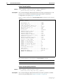
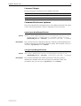
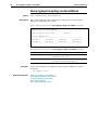
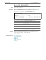
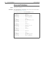
Allied Telesis announces the release of Software Version 2.9.1 on the products
in the following table. This Release Note describes the new features and
enhancements.
Product series
Models
x900-48FE
x900-48FE, x900-48FE-N
AT-9900
AT-9924T, AT-9924SP, AT-9924T/4SP
AT-8900
AT-8948
AT-9800
AT-9812T, AT-9816GB
Rapier i
Rapier 24i, Rapier 48i, Rapier 16fi
AT-8800
AT-8824, AT-8848
AT-8700XL
AT-8724XL, AT-8748XL
AT-8600
AT-8624T/2M, AT-8624POE, AT-8648T/2SP
AR700
AR725, AR745, AR750S, AR750S-DP, AR770S
AR400
AR415S, AR440S, AR441S, AR442S, AR450S
The product series that each feature and enhancement applies to are shown in
“Overview of New Features” on page 7. This Release Note should be read in
conjunction with the Installation and Safety Guide or Quick Install Guide,
Hardware Reference, and Software Reference for your router or switch. These
documents can be found on the Documentation and Tools CD-ROM packaged
with your router or switch, or:
www.alliedtelesis.com/support/software
This Release Note has the following structure:
1.
Upgrading to Software Version 2.9.1
This section lists the names of the files that may be downloaded from the
web site.
2.
Overview of New Features
This section lists the new features and shows the product families on which
each feature is supported.
3.
Descriptions of New Features
These sections describe how to configure each new feature.
Caution: Information in this document is subject to change without notice and
does not represent a commitment on the part of Allied Telesis Inc. While every
effort has been made to ensure that the information contained within this
document and the features and changes described are accurate, Allied Telesis
Inc. can not accept any type of liability for errors in, or omissions arising from,
the use of this information.
Software Version 2.9.1
C613-10486-00 REV C
4
Upgrading to Software Version 2.9.1
Release Note
Upgrading to Software Version 2.9.1
Software Version 2.9.1 is available as a flash release that can be downloaded
directly from the Software/Documentation area of the Allied Telesis website:
www.alliedtelesis.com/support/software
For information about licencing this release, see “Release Licences” on page 5.
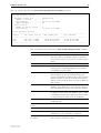
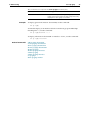
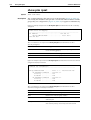
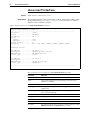
The following table lists the file names for Software Version 2.9.1.
Product name
Release file
GUI resource file
CLI help file
AT-9924T
89-291.rez
9924_291-00_en_d.rsc
9-291321.hlp
AT-9924SP
89-291.rez
9924_291-00_en_d.rsc
9-291321.hlp
AT-9924T/4SP
89-291.rez
9924_291-00_en_d.rsc
9-291321.hlp
AT-8948
89-291.rez
—
9-291321.hlp
x900-48FE
89-291.rez
—
9-291321.hlp
x900-48FE-N
89-291.rez
—
9-291321.hlp
AT-9812T
sb-291.rez
9812_291-00_en_d.rsc
98-291a.hlp
AT-9816GB
sb-291.rez
9816_291-00_en_d.rsc
98-291a.hlp
Rapier16fi
86s-291.rez
r16i_291-00_en_d.rsc
rp-291a.hlp
Rapier 24i
86s-291.rez
r24i_291-00_en_d.rsc
rp-291a.hlp
Rapier 48i
86s-291.rez
r48i_291-00_en_d.rsc
rp-291a.hlp
AT-8824
86s-291.rez
8824_291-00_en_d.rsc
88-291a.hlp
AT-8848
86s-291.rez
8848_291-00_en_d.rsc
88-291a.hlp
AT-8724XL
87-291.rez
8724_291-00_en_d.rsc
87-291a.hlp
AT-8748XL
87-291.rez
8748_291-00_en_d.rsc
87-291a.hlp
AT-8624POE
sr-291.rez
8624poe_291-00_en_d.rsc
86-291a.hlp
AT-8624T/2M
sr-291.rez
8624t_291-00_en_d.rsc
86-291a.hlp
AT-8648T/2SP
sr-291.rez
8648t_291-00_en_d.rsc
86-291a.hlp
AR770S
55-291.rez
AR750S-DP
55-291.rez
750s_291-00_en_d.rsc
700-291a.hlp
AR750S
55-291.rez
750s_291-00_en_d.rsc
700-291a.hlp
AR725
52-291.rez
725_291-00_en_d.rsc
700-291a.hlp
AR745
52-291.rez
745_291-00_en_d.rsc
700-291a.hlp
AR440S
54-291.rez
440s_291-00_en_d.rsc
400-291a.hlp
AR441S
54-291.rez
441s_291-00_en_d.rsc
400-291a.hlp
AR442S
54-291.rez
442s_291-00_en_d.rsc
400-291a.hlp
AR415S
54-291.rez
415s_291-00_en_d.rsc
400-291a.hlp
AR450S
54-291.rez
450s_291-00_en_d.rsc
400-291a.hlp
—
700-291a.hlp
Software Version 2.9.1
C613-10486-00 REV C
Software Version 2.9.1
5
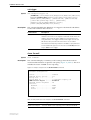
Release Licences
Release licences are valid for all releases for switches and routers manufactured
at the end of 2006. This means you can upgrade on these devices without
entering the enable release command.
If you already have a device, contact your Allied Telesis representative for
information about licencing. If you are not sure whether your device licence is
valid for all releases, use the following command:
show release
If your router or switch does not have the following output, contact your Allied
Telesis representative to request a licence.
Release
Licence
Period
----------------------------------------------------any
full
-----------------------------------------------------
A new release licence is not required when you are updating to a minor or
maintenance release. This change affects release licences only, and not special
feature licences.
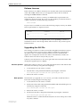
Upgrading the GUI File
The naming convention for GUI resource files changed from Software Version
2.8.1 onwards. Names are now longer, and they include more information
about the router or switch model and software version to which the file
applies. For example, the GUI resource file for AT-9924 Series switches for
Software Version 291-01 is 9924_291-01_en_d.rsc.
Software versions before 2.8.1 do not recognise the new GUI name format. This
changes the upgrade process slightly.
Previous process
With earlier software versions, you could upgrade the release file and the GUI
file at the same time, by using the following steps:
1.
Load each file onto the router or switch.
2.
Set both files as the preferred install files, by using the command:
set install=pref rel=new-rez-file gui=new-gui-file
3.
New process
Reboot the router or switch.
The first time you upgrade to a 2.9.1 version, you need to install the release
before the GUI, by using the following steps:
1.
Load each file onto the router or switch.
2.
Set the new release file as the preferred install file and uninstall the previous
GUI file, by using the command:
set install=pref rel=291-rez-file gui=
3.
Reboot the router or switch.
4.
Set the new GUI file as the preferred GUI file, by using the command:
set install=pref gui=291-gui-file
While the router or switch installs the GUI, the console is unresponsive. This
may take a minute.
Software Version 2.9.1
C613-10486-00 REV C
6
Upgrading to Software Version 2.9.1
Release Note
If you upgrade from a 2.9.1 version to a later 2.9.1 maintenance version, you
can install the release and GUI in the same step.
Also, some TFTP servers do not support filenames longer that 8 characters and
therefore will not allow you to load the file from the server. With such servers,
you can simply rename the GUI file to a short name on the TFTP server, then
rename it correctly on the router or switch.
Backwards Compatibility
If you have scripts that use the following features, you need to be aware that
the behaviour has changed:
■
The group parameter in the add vlan port is now mandatory when you
add a trunk group to a private vlan as private ports (see Group Parameter
Required for Private VLAN Ports).
■
The delete dhcpsnooping binding command has a new mandatory ip
parameter (see Adding Default Access Routers to Static Entries).
■
The pairmode parameter in the set shdsl command has new options that
replace the options 4wire and 2pair (see ITU Standard Mode Operation).
When configuring an SHDSL interface to transmit data over a 4 wire
connection, you must now specify whether it is a standard connection
using the options 4wires or 2pairs, or an enhanced connection using the
options, 4wiree or 2paire.
Software Version 2.9.1
C613-10486-00 REV C
Software Version 2.9.1
7
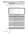
Overview of New Features
AT-8600: GUI Support for AT-8624POE and AT-8648T/2SP
!
AT-8600: Protocol Independent Multicast (PIM) Support
!
AT-8600: AT-8624POE Fan Enhancements
!
AT-8600: Support for AT-45/xx series and AT-47 Expansion
Modules
!
AR400: VPN Configuration Wizards
AT-9900
x900-48FE
AT-8900
AT-9800
AT-8600
AT-8700XL
AT-8800
Rapier
AR700
AR400
The following table lists the new features and enhancements by product series.
For supported models, see “Introduction” on page 3.
!
!
System: Activate Findme Feature
System: Enhanced Protection for Filenames
! ! ! ! ! ! ! ! ! !
System: Increased Module Support by Show Debug Active
! ! ! ! ! ! ! ! ! !
Switching: Multiple Uplink Ports in Private VLANs
! ! ! !
Switching: Group Parameter Required for Private VLAN Ports
! ! ! !
!
PoE: PoE Firmware Upgrade
SHDSL: ITU Standard Mode Operation
!
Bridging: VLAN to WAN Bridging
! !
Bridging: Retaining or Stripping VLAN Tags
! !
IP: Dynamic DNS Client
! !
IP: Preventing MAC Address Resolution Between Hosts
Within a Subnet
! ! ! ! ! ! ! ! ! !
IP: IP Debug Timeout
! ! ! ! ! ! ! ! ! !
IP: Show IP Interface Command Displays Gratuitous ARP
Status
! ! ! ! ! ! ! ! ! !
DHCP: DHCP Options
! ! ! ! ! ! ! ! ! !
DHCP snooping: Adding Default Access Routers to Static
Entries
! ! ! !
! ! !
DHCP snooping: Filtering Broadcast and Multicast Packets
! ! ! !
! ! !
MAC-Forced Forwarding: MAC-Forced Forwarding
! ! ! !
! ! !
!
IP multicasting: PIM Support on AT-8600 Series Switches
IP multicasting: Query Solicitation
! ! ! ! ! ! ! !
OSPF: Neighbour Retransmission List Debugging
! ! ! ! ! ! ! ! ! !
BGP-4: Improved BGP Route Selection
! ! ! !
! ! ! !
BGP-4: Improved BGP Backoff Show Command Output
! ! ! !
! ! ! !
IPv6: Setting a Metric for RIPv6
! ! ! !
! ! ! !
Software Version 2.9.1
C613-10486-00 REV C
AT-9900
x900-48FE
AT-8900
AT-9800
AT-8600
AT-8700XL
AT-8800
Rapier
Release Note
AR700
Overview of New Features
AR400
8
IPv6: Additional Show Command Filtering
! ! ! !
Firewall: Using Automatic Client Management to Manage SIP
Sessions
! ! ! !
Firewall: Setting a Trigger for Automatic Client Management
! ! ! !
Firewall: Limiting Firewall Sessions from a Device
! ! ! !
!
Firewall: Monitoring Firewall Sessions using SNMP
! ! ! !
!
Firewall: Dynamic Renumbering of Firewall Rules
! ! ! !
!
IPsec: Additional RFC and Draft Compliance for NAT-T
! ! ! !
IPsec: Increase to Maximum Number of IPsec SA Bundles
! ! ! !
IPsec: Improved Debugging Options for IPsec and ISAKMP
! ! ! !
IPsec: Improved Output for IPsec and ISAKMP Counters
! ! ! !
IPsec: Modified Expiry Timeout Limit for Security
Associations
! ! ! !
LLDP: Link Layer Discovery Protocol
! ! ! ! ! ! ! ! ! !
Management Stacking: Changes to Local Commands
! ! ! !
! ! ! !
! ! !
Software Version 2.9.1
C613-10486-00 REV C
Software Version 2.9.1
9
AT-8600 Series Switch Enhancements
This Software Version includes the following enhancements for the AT-8600
Series switches:
■
GUI Support for AT-8624POE and AT-8648T/2SP
■
Protocol Independent Multicast (PIM) Support
■
AT-8624POE Fan Enhancements
■
Support for AT-45/xx series and AT-47 Expansion Modules
This section describes the enhancements.
GUI Support for AT-8624POE and AT-8648T/2SP
Software Version 2.9.1 introduces support in the GUI module to allow loading
and execution of GUI resource files on AT-8624POE and AT-8648T/2SP
switches.
Previously, in the AT-8600 range of switches, GUI support was available for the
AT8624T/2M only. Now, all GUI pages that are available for the AT8624T/2M
switch, are also available for the AT-8624POE and AT-8648T/2SP switches.
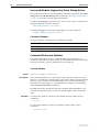
Protocol Independent Multicast (PIM) Support
This Software Version introduces Protocol Independent Multicast (PIM) on the
AT-8600 Series switches. For information about configuring PIM on your
switch, see the IP Multicasting chapter at the end of this Release Note.
When running Software Version 2.9.1 on an AT-8600 Series switch, you will
need a special feature licence to use PIM. Contact your authorised Allied
Telesis distributor or reseller for details and passwords of feature licences.
AT-8624POE Fan Enhancements
This Software Version includes enhanced control over the AT-8624POE switch
fan speed. Previously, in a situation where mechanical problems in the fan
cause the software to generate multiple alarms, this could result in the fan
speed repeatedly changing. To prevent this, the fan speed is now automatically
set to the maximum speed if the fan reports an error more than 3 times in any
1-hour period.
This Software Version also includes support for the new 7000RPM fan and the
associated mod level of M2-2, for AT-8624POE switches.
Software Version 2.9.1
C613-10486-00 REV C
10
AT-8600 Series Switch Enhancements
Release Note
Support for AT-45/xx series and AT-47 Expansion
Modules
Previously, the AT-8600 Series switches supported the AT-A46 expansion
module only. New in this Software Version is support for AT-A45/xx series and
AT-A47 expansion modules on the AT-8600 Series switches.
The following shows the complete list of currently supported expansion
modules:
Expansion Module
Port Type
Connector Type
AT-A45/MT
100Base-FX
MT-RJ
AT-A45/SC
100Base-FX
SC
AT-A45/SC-SM15
100Base-FX
SC
AT-A46
10/100/1000BASE-T
RJ-45
AT-A47
1000Base-T (GBIC)
GBICs are sold
separately
Software Version 2.9.1
C613-10486-00 REV C
Software Version 2.9.1
11
AR400 Series Router Enhancements
This Software Version includes the following enhancement for the AR400
Series switches:
■
VPN Configuration Wizards
This section describes the enhancement.
VPN Configuration Wizards
This enhancement makes it simple to configure VPNs on AR415S, AR440S,
AR441S, and AR442S routers. The web-based GUI for these routers now
includes new wizards for setting up:
■
site-to-site VPNs, for secure communication between the local LAN and
LANs at remote sites
■
remote access VPNs, for remote user access to the local LAN through
secure connections
The wizards ask you to enter a few details, from which they configure all the
settings the VPN requires, including:
■
Encryption to protect traffic over the VPN
■
ISAKMP with a pre-shared key to manage the VPN key transfer
■
the firewall, to protect the LANs and to allow traffic to use the VPN
■
Network Address Translation (NAT), so that you can access the Internet
from the private LAN through a single public IP address. This Internet
access does not interfere with the VPN solution.
■
NAT-Traversal, if necessary
■
L2TP, PPP and user settings for remote access VPNs
All wizard-created VPN tunnels use the same WAN interface, and use vlan1 as
the LAN interface.
The first time you use the GUI it opens on the Wizards page. After initial
configuration, it may instead open on the System Status page. To access the
wizards from there, click on the Wizards button in the left-hand menu.
For examples of how to use the site-to-site VPN wizard, see the following How
To Notes:
Software Version 2.9.1
C613-10486-00 REV C
■
How To Use the Allied Telesis GUI to Customise the Router and Set Up
Connections
■
How To Use the Allied Telesis GUI Wizard to Create a Site-to-Site VPN through a
NAT Gateway Device. Use this Note when both ends of your VPN are Allied
Telesis routers.
■
How To Use the Allied Telesis GUI Wizard to Create a Site-to-Site VPN. Use this
Note when both ends of the VPN are Allied Telesis routers and the VPN
does not go through a NAT gateway device.
■
How To Create a VPN between an Allied Telesis and a SonicWALL router, with
NAT-T
■
How To Create a VPN between an Allied Telesis and a NetScreen router
12
AR400 Series Router Enhancements
Release Note
These How To Notes are available in the Resource Center of the
Documentation and Tools CDROM for Software Version 2.9.1, or from
www.alliedtelesis.co.uk/site/solutions/techdocs.asp?area=howto.
Command Changes
This enhancement does not affect any commands.
Software Version 2.9.1
C613-10486-00 REV C
Software Version 2.9.1
13
System Enhancements
This Software Version includes the following enhancements to the System:
■
Activate Findme Feature
■
Enhanced Protection for Filenames
■
Increased Module Support by Show Debug Active
This section describes the enhancements. The new and modified commands to
implement them are described in Command Reference Updates.
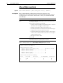
Activate Findme Feature
On AT-8800 Series switches, Software Version 2.9.1 enables you to physically
locate a specific switch from others that are co-located. Running the activate
findme command causes all switch port LEDs to flash green and amber at a
rate of 0.5Hz. Normal LED behaviour will be restored automatically after
either the default time, or specified time, has elapsed. The time parameter
specifies the time period until normal LED behaviour is restored.
To locate a specific AT-8800 Series switch by causing its LEDs to flash, use the
command:
activate findme [time=time]
To stop the LEDs from flashing, use the command:
deactivate findme
Command Changes
The following table summarises the new commands:
Command
Change
activate findme
New command
deactivate findme
New command
Enhanced Protection for Filenames
This Software Version protects the preferred software release and current boot
configuration files from being renamed.
Previously, you could rename the current boot configuration file using the
command rename. This stopped the router or switch from running that
configuration on boot-up, so if the router or switch restarted after the user had
renamed the current boot configuration file, it started up with no
configuration.
Command Changes
This enhancement does not affect any commands.
Software Version 2.9.1
C613-10486-00 REV C
14
System Enhancements
Release Note
Increased Module Support by Show Debug Active
This Software Version increases the number of modules supported by the show
debug active and disable debug active commands. See “Supported Modules”
on page 15 for the list of newly supported modules.
To display the debugging options that are active on the router or switch for the
supported modules, use the command:
show debug active={all|module}
To disable debugging on the supported modules, use the command:
disable debug active={all|module}
Command Changes
The following table summarises the modified commands:
Command
Change
disable debug active
New module options for active parameter
show debug active
New module options for active parameter
Command Reference Updates
This section describes each new command and the changed portions of
modified commands and output screens. For modified commands and output,
the new parameters, options, and fields are shown in bold.
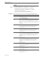
activate findme
Syntax
Description
ACTivate FINdme [TIme=time]
This command enables you to physically locate a specific switch from others
that are co-located. This command causes the switch’s LEDs to flash green and
amber at a rate of 0.5 Hzs. Normal LED behaviour is restored automatically
after either the default time, or a specified time, has elapsed, or manually by
using the deactivate findme command.
The time parameter specifies the time period until normal LED behaviour is
restored. The duration can be set between 10 and 3600 seconds. The default
is 60.
Examples
To activate the “find me” feature for the default amount of time, use the
command:
act fin
To activate the “find me” feature for 2 minutes (120 seconds), use the
command:
act fin ti=120
Software Version 2.9.1
C613-10486-00 REV C
Software Version 2.9.1
15
deactivate findme
Syntax
Description
Example
DEACTivate FINdme
This command deactivates the findme LED flash pattern and returns the LED
displays to their normal mode.
To deactivate the “find me” feature, use the command:
deact fin
disable debug active
Syntax
DISable DEBug ACTive={ALL|module}
where module is the predefined name of a module
Description
This command disables currently enabled debugging, either for a specific
module or for all modules. This command now supports additional modules.
See “Supported Modules” on page 15 for a list of additional modules.
show debug active
Syntax
SHow DEBug ACTive={ALL|module}
where module is the predefined name of a module
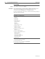
Description
This command displays information about module-specific debugging
currently enabled on the router or switch. The following table lists the new
modules supported by this command and their related debug commands.
Please note that your router or switch, depending on its feature set, may not
support all the modules included this list.
Supported Modules
Module
Related Debugging Commands
BOOTp
disable bootp relay option82 debug
enable bootp relay option82 debug
BRI
disable bri debug
enable bri debug
show bri debug
(BRI driver)
Software Version 2.9.1
C613-10486-00 REV C
DHCP
disable dhcp debug
enable dhcp debug
DHCP6
disable dhcp6 debug
enable dhcp6 debug
DHCPSnooping
disable dhcpsnooping debug
enable dhcpsnooping debug
DVMrp
disable dvmrp debug
enable dvmrp debug
ENCO
disable enco debugging
enable enco debugging
16
System Enhancements
Release Note
Module
Related Debugging Commands
FIREwall
disable firewall policy debug
enable firewall policy debug
FRamerelay
disable framerelay debug
enable framerelay debug
GARP
disable garp debug
enable garp debug
show garp debug
GRE
disable gre debug
enable gre debug
HTTP
disable http debug
enable http debug
show http debug
IPSec
disable ipsec policy debug
enable ipsec policy debug
IPV6
disable ipv6 debug
disable ipv6 mld debug
disable mldsnooping debug
enable ipv6 debug
enable ipv6 mld debug
enable mldsnooping debug
show ipv6 mld debug
ISAkmp
disable isakmp debug
enable isakmp debug
LOADBalancer
disable loadbalancer debug
enable loadbalancer debug
LDAP
disable ldap debug
enable ldap debug
LLDP
disable lldp cdp debug
enable lldp cdp debug
MAIL
disable mail debug
enable mail debug
PIM6
disable pim6 debug
enable pim6 debug
show pim6 debug
PING
disable ping poll debug
enable ping poll debug
PKI
disable pki debug
enable pki debug
POE
disable poe debug
enable poe debug
PORTAuth
disable portauth debug
enable portauth debug
PPP
disable ppp debug
disable ppp template debug
enable ppp debug
enable ppp template debug
PRI
disable pri debug
enable pri debug
(PRI driver)
Software Version 2.9.1
C613-10486-00 REV C
Software Version 2.9.1
Software Version 2.9.1
C613-10486-00 REV C
17
Module
Related Debugging Commands
QOS
disable qos debug
enable qos debug
RSVP
disable rsvp debug
enable rsvp debug
SHDsl
disable shdsl debug
enable shdsl debug
SQOS
(Software QOS)
disable sqos debug
enable sqos debug
SSH
disable ssh debug
enable ssh debug
SSL
disable ssl debug
enable ssl debug
STAck
disable stack debug
enable stack debug
STAR
disable star debugging
enable star debugging
TCP
enable tcp debug
disable tcp debug
TELnet
disable rtelnet debug
enable rtelnet debug
VLAN
disable vlan debug
enable vlan debug
show vlan debug
VOIP
disable voip debug
enable voip debug
WANLB
disable wanlb debug
enable wanlb debug
18
Switching Enhancements
Release Note
Switching Enhancements
This Software Version includes the following enhancements to Switching:
■
Multiple Uplink Ports in Private VLANs
■
Group Parameter Required for Private VLAN Ports
This section describes the enhancements. The modified commands to
implement them are described in Command Reference Updates.
Multiple Uplink Ports in Private VLANs
This enhancement makes it possible to add multiple uplink ports to a private
VLAN on Rapier i, AT-8600, AT-8700XL, and AT-8800 Series switches. This
enables you to use private VLANs in a ring or meshed topology.
To add the uplink ports, specify the list of ports in the existing command:
add vlan={vlan-name|1..4094} port=port-list
[frame={untagged|tagged}] uplink
For Rapier 48i and AT-8748XL switches, note that all ports in the private VLAN
must be in the same switch instance. See the Switching chapter of the Software
Reference for more information.
Command Changes
This enhancement does not affect any commands.
Group Parameter Required for Private VLAN Ports
With Software Version 2.9.1, when you add a trunk group to a private vlan as
private ports, you must specify the group parameter.
The add switch trunk and create switch trunk commands now check that all
ports belong to the same group if they belong to the same private VLAN.
Command Changes
The following table summarises the modified command:
Command
Change
add vlan port
Modified behaviour for the group parameter
Software Version 2.9.1
C613-10486-00 REV C
Software Version 2.9.1
19
Command Reference Updates
This section describes the changed portions of the modified command. The
modified parameter is shown in bold.
add vlan port
Syntax
Description
Software Version 2.9.1
C613-10486-00 REV C
ADD VLAN={vlan-name|1..4094} POrt={port-list|ALL}
[FRAme={TAGged|UNTAGged}] [UPLINk] [GROUP]
When adding a trunk group to a private VLAN as private ports, you now must
specify the group parameter.
20
Power Over Ethernet Enhancements
Release Note
Power Over Ethernet Enhancements
This Software Version includes the following enhancement to Power over
Ethernet (PoE):
■
PoE Firmware Upgrade
This section describes the enhancement. The new commands to implement it
are described in Command Reference Updates.
PoE Firmware Upgrade
Software Version 2.9.1 introduces the ability to upgrade PoE firmware via the
CLI. In addition, you can also enable and disable a range of debugging modes
for Power over Ethernet.
Command Changes
The following table summarises the new commands:
Command
Change
disable poe debug
New command
enable poe debug
New command
set poe firmware
New command
show poe version
New command
Command Reference Updates
This section describes each new command.
disable poe debug
Syntax
Description
DISable POE DEBug=[ALL|DEBug|TRAce|ERRor|FATal|TESt]
This new command disables the specified PoE debugging modes.
Parameter
DEBug
Description
The debugging modes to disable.
Default: all
ALL
DEBug
Disables all PoE debugging
TRAce
Disables only high-level, essential debugging, for
example, information about message types
ERRor
FATal
Disables only the debugging of any error conditions
that may occur during PoE operation.
TESt
Disables only the test debugging mode
Software Version 2.9.1
C613-10486-00 REV C
Software Version 2.9.1
Examples
21
To disable all PoE debugging, use one of the commands:
dis poe deb=all
dis poe debug=deb
To disable high-level, essential debugging, use the command:
dis poe deb=tra
enable poe debug
Syntax
Description
ENAble POE DEBug=[ALL|DEBug|TRAce|ERRor|FATal|TESt]
This new command enables the specified PoE debugging modes.
Parameter
Description
DEBug
The debugging modes to enable.
Default: all
Example
ALL
DEBug
Enables all PoE debugging
TRAce
Enables only high-level, essential debugging, for
example, information about message types
ERRor
FATal
Enables only the debugging of any error conditions that
may occur during PoE operation.
TESt
Enables only the test debugging mode
To enable error debugging, use one of the commands:
ena poe deb=err
ena poe deb=fat
set poe firmware
Syntax
SET POE FIRMware=filename
where filename is the name of a valid firmware file that is already present in the
flash. A valid firmware file must be either Version 2.9.0 or 5.0.1, and have the
extension .s19.
Description
This new command upgrades the PoE firmware in the PoE Controller, if the
AT-8600 Series switch finds valid PoE firmware in its flash. Firmware is
downloaded to the flash using the load command. See the Managing
Configuration Files and Software Versions chapter in the Software Reference for
command details.
The switch prompts you for confirmation before it begins upgrading the
firmware. The upgrade may take a while to complete, depending on the size of
your firmware file.
You must not restart the switch while the firmware upgrade is in progress. If
you restart the switch, the firmware upgrade will terminate abruptly, which will
corrupt the firmware and cause PoE operations to fail in the subsequent startup.
Software Version 2.9.1
C613-10486-00 REV C
22
Power Over Ethernet Enhancements
Release Note
During the upgrade the following limitations apply:
■
Other PoE commands do not execute.
■
You cannot use any PoE ports for powered devices, as Power over Ethernet
is temporarily disabled. However, any non-powered devices that are
connected to PoE ports will continue to operate normally.
■
You should avoid deleting, re-naming, or copying any files.
All PoE configurations are restored once the upgrade has successfully
completed. You do not need to reconfigure PoE or restart the switch for the
new firmware to take effect.
The new firmware version is permanently stored in the PoE hardware. This
remains in the PoE hardware even if you delete the .sig file from flash memory.
Example
To download the PoE firmware file v2.9.0 to the PoE Controller, use the
command:
set poe firm=pol30k.s19
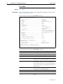
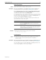
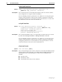
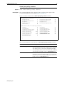
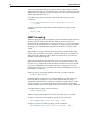
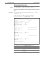
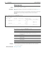
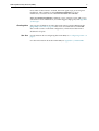
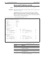
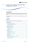
show poe version
Syntax
Description
SHow POE VERsion
Use this command to display the version number of the PoE firmware that is
currently running on your AT-8600 Series switch.
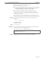
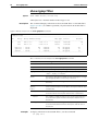
Figure 1: Example output from the show poe version command
PoE version information:
Firmware version .... 2.9.0
Example
To display the PoE firmware version number, use the command:
sh poe ver
Software Version 2.9.1
C613-10486-00 REV C
Software Version 2.9.1
23
SHDSL Enhancements
This Software Version includes the following enhancement to SHDSL:
■
ITU Standard Mode Operation
This section describes the enhancement. The modified commands to
implement it are described in Command Reference Updates.
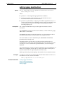
ITU Standard Mode Operation
On the AR442S router, Software Version 2.9.1 enables you to set SHDSL
operation for either standards-based, or enhanced 2-pair, modes of operation.
The standards-based 2-pair mode is compatible with ITU standard G.991.2
(12/2003). The Enhanced 2-pair mode was initially developed prior to the
finalization of the ITU standard, and is therefore not compatible with
standards-based DSLAMs. Standards-based 2-pair mode is advisable for most
installations, but enhanced mode may be useful in circumstances where it is
compatible with the DSLAM.
To set the wire mode for SHDSL, use the command:
set shdsl=interface
[pairmode={2wire|4wirestandard|4wireenhanced|
1pair|2pairstandard|2pairenhanced}] [other-options]
To see the wire mode that an SHDSL interface is set to, use the command:
show shdsl={interface|all} linedetails
Command Changes
The following table summarises the modified commands:
Software Version 2.9.1
C613-10486-00 REV C
Command
Change
set shdsl
New options for pairmode parameter
show shdsl linedetails
New Pair mode field in output
24
SHDSL Enhancements
Release Note
Command Reference Updates
This section describes the changed portions of modified commands and output
screens. The new parameters, options, and fields are shown in bold.
set shdsl
Syntax
SET SHDsl=interface [MOde={CPE|CO}]
[PAIRmode={2Wire|4WIREStandard|4WIREEnhanced|
1Pair|2PAIRStandard|2PAIREnhanced}]
[STAndard={ANNEXA|ANNEXB|BOTH|ANNEXBAnfp|BOTHAnfp}]
[PSDmask={SYMmetric|ASYMetric}] [AUTOretrain={ON|OFF}]
[BITratemode=ADAptive|FIXed] [MINbitrate=72..4624]
[MAXbitrate=72..4624] [ATTENuationthreshold=0..31]
[SNRmarginthreshold=0..15]
Description
This command configures the SHDSL interface. The SHDSL interface must be
disabled using the disable shdsl command before any parameters can be
configured on the interface.
Parameter
Description
PAIRmode
Selects whether the SHDSL interface attempts to transmit data over
1 pair or 2 pairs (2 wires or 4 wires). For 2 pair operation the
parameter also selects either a standards-based mode, or a
non-standards based enhanced mode.
Default: 1Pair
Example
1Pair,
2Wire
A single pair of wires (2 wires).
2PAIRStandard,
4WIREStandard
Two pairs of wires (4 wires) operating in
standards based mode (ITU standard G.991.2).
In this mode, the bitratemode parameter must
be set to fixed. Automatic fallback to
single-pair mode is not supported.
2PAIREnhanced,
4WIREEnhanced
Two pairs of wires (4 wires) operating in
non-standards based, enhanced mode. In this
mode, the bitratemode parameter must be set
to fixed. Automatic fallback to single-pair
mode is supported by compatible DSLAMs.
To set SHDSL interface 0 to 2pairstandard mode, use the command:
set shd=0 pair=2pairs bit=fix max=4624
Software Version 2.9.1
C613-10486-00 REV C
Software Version 2.9.1
25
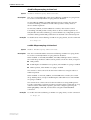
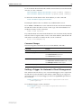
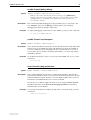
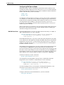
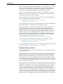
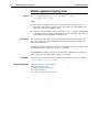
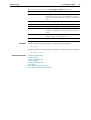
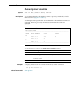
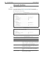
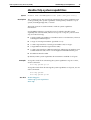
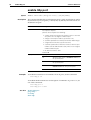
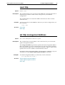
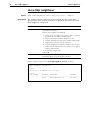
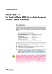
show shdsl linedetails
Syntax
Description
SHow SHDsl={interface|ALL} LINEdetails
This command displays the current negotiated configuration information for
the specified SHDSL interface or all SHDSL interfaces. If the SHDSL interface is
not in the data state, the parameters displayed in the output are the last
received or known parameters for the connection.
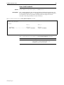
Figure 2: Example output from the show shdsl linedetails command
SHDSL Line Details
------------------------------------------------------------------------------shdsl0:
Pair 1
Pair 2
----------Standard .................... Annex A
Annex A
Pair mode ................... 2 pair standard
2 pair standard
.
.
.
Table 1: New parameters in the output of the show shdsl linedetails command
Software Version 2.9.1
C613-10486-00 REV C
Parameter
Meaning
Pair mode
Whether the SHDSL line is operating in 1-pair or 2-pair
mode, and if in 2-pair mode whether it is in
standards-based or enhanced mode.
26
Bridging Enhancements
Release Note
Bridging Enhancements
This Software Version includes the following enhancements to Bridging:
■
VLAN to WAN Bridging
■
Retaining or Stripping VLAN Tags
This section describes the enhancements. The new and modified commands to
implement them are described in Command Reference Updates.
VLAN to WAN Bridging
Software Version 2.9.1 includes the ability to bridge between VLANs over a
PPP WAN link.
In general, it is better to route a protocol than to bridge it. However, sometimes
bridging is a more appropriate solution, particularly where unroutable upper
layer protocols are used. These protocols sometimes produce high levels of
broadcast messages that can overload a network, an effect that gets
progressively worse as the number of devices increases. Although this
situation may not pose a problem to the high bandwidths available on local
area networks, it could heavily congest the more limited bandwidths available
on wide area links. This effect can be reduced by adding a VLAN to a bridge
and then limiting the VLAN to devices that require wide area connections. The
remote VLAN bridge is able to support up to 16 VLANs.
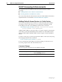
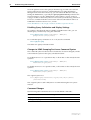
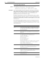
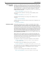
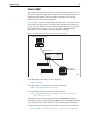
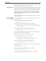
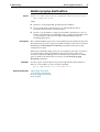
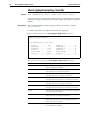
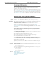
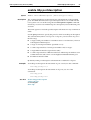
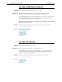
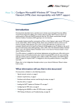
Internal Representation of the VLAN-to-WAN Bridge
The router contains both a switch module and a bridge module. This section
explains how these modules provide the learning and forwarding functions for
the VLAN-to-WAN bridge.
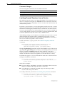
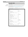
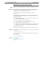
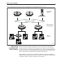
Figure 3 shows an internal representation of the VLAN-to-WAN bridge that
exists on the AR400 and AR700 Series routers. Note that the bridge and switch
symbols are internal functional representations and are not standalone devices.
Figure 3: Internal representation of the switch’s VLAN-to-WAN bridge
Switch
Forwarding
Database
Bridge
Station
Map
VLAN B
Switch Ports
Switch
Module
Bridge
Module
Internal
Connection
Single
Virtual
Port
VLAN A
Switch Ports
BRG7_R
Software Version 2.9.1
C613-10486-00 REV C
Software Version 2.9.1
27
Switch ports within each VLAN connect to the switch module, to obtain layer
two connectivity (local or remote) for their attached devices. An internal data
path, shown by the horizontal grey arrow, provides connectivity between the
two modules.
The VLAN-to-WAN Bridging Process
The switch module provides layer two connectivity for locally attached ports
within the same VLAN. An internal data connection, shown by the horizontal
grey arrow in Figure 3, provides connectivity between the two modules. The
switch forwarding database, and the bridge station map both employ their own
respective processes to learn the addresses of their attached devices.
Local devices within the same VLAN, utilise the forwarding database and their
traffic is switched by hardware at layer two. Remote devices within the same
VLAN, utilise both the forwarding database and the station map, hence their
traffic is remote bridged across the wide area link.
The switch module examines the MAC addresses of frames received on its
switch ports. If it recognises an address as belonging to a locally attached
device, it forwards the frame to the appropriate port. If it recognises a frame’s
MAC address as belonging to a device residing over the wide area link, it
forwards the frame to the bridge module via the internal connection shown.
The bridge module then forwards the frame across the wide area link.
VLAN-to-WAN data always crosses the wide area link as tagged frames. At the
link’s remote end, the bridge may either retain the VID tags for forwarding the
frames to a tagged port, or remove the VID tags for forwarding the frames to
an untagged port within the VLAN. For this reason, you must set the set
bridge stripvlantag command to off.
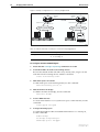
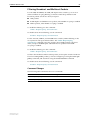
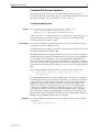
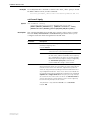
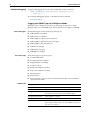
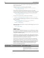
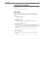
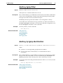
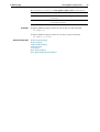
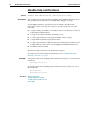
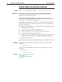
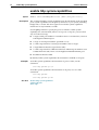
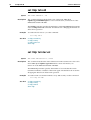
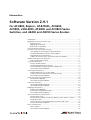
VLAN-to-WAN Bridge Configuration
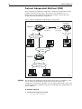
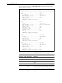
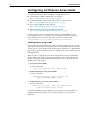
Figure 4 shows a simple remote VLAN connection. A company has its head
office at location A and its training centre at location B. In location B, a training
server provides computer based training programs that are accessible from
selected user PCs located at both sites. Unfortunately, the training application
operates over an unroutable protocol.
To solve this problem, a single VLAN is created for the training PCs and a
remote VLAN connection lets them access the wide area link.
Software Version 2.9.1
C613-10486-00 REV C
28
Bridging Enhancements
Release Note
Figure 4: Example configuration for a remotely bridged VLAN
Bridge A
Bridge B
(Virtual)
Port 1
(Virtual)
Port 1
PPP Link
Switch Port 11
Switch Port 21
Switch Port 22
Switch Port 12
Training VLAN VID=2
Training VLAN VID=2
Training
Server
BRG5
Table 2: VLAN membership in example of a network using tagged ports
VLAN
Member ports
Training
11, 12 on Bridge A
21, 22 on Bridge B
To configure VLAN-to-WAN bridge A
1.
Ensure that the set bridge stripvlantag command is set to OFF.
2.
Create the VLAN to be used for the training devices.
Because the default VLAN with VID 1 may already exist, assign a VLAN
with VID 2 for the training devices with the command:
create vlan=Training vid=2
3.
Add switch ports to the VLAN.
To add switch ports to the Training VLAN, use the command:
add vlan=Training port=11,12
4.
Add the VLAN to the bridge.
To add the VLAN to the bridge, use the command:
add vlan=2 bridge
5.
Create a WAN interface.
To create a PPP interface over a synchronous port or other interface, use the
command:
create ppp=0 over=syn0
6.
Configure the bridge ports.
To enable the bridge module and add the PPP interface as a virtual port,
use the commands:
enable bridge
set bridge stripvlantag=no
add bridge port=1 int=ppp0
Software Version 2.9.1
C613-10486-00 REV C
Software Version 2.9.1
29
To configure VLAN-to-WAN bridge B
1.
Create the Training VLAN.
To create a Training VLAN with VID 2 to be used for VLAN-to-WAN
bridging, use the command:
create vlan=Training vid=2
2.
Add switch ports to the VLAN.
To add switch ports to the Training VLAN, use the command:
add vlan=Training port=21,22
3.
Add the VLAN to the bridge.
To add the VLAN to the bridge, use the command:
add vlan=2 bridge
4.
Create a WAN interface.
To create a PPP interface over a synchronous port or other interface, use the
command:
create ppp=0 over=syn0
5.
Configure the bridge ports.
To enable the bridge module and add the PPP interface as a virtual port,
use the commands:
enable bridge
set bridge stripvlantag=no
add bridge port=1 int=ppp0
For more information about configuring Frame Relay and PPP, see the
Point-to-Point Protocol (PPP) chapter of your Software Reference.
Command Changes
The following table summarises the new commands:
Software Version 2.9.1
C613-10486-00 REV C
Command
Change
add vlan bridge
New command
delete vlan bridge
New command
30
Bridging Enhancements
Release Note
Retaining or Stripping VLAN Tags
By default, when an AR400 or AR700 Series router receives a tagged packet on
an Eth or VLAN interface and bridges it, the bridge strips out the packet’s
VLAN tag. This enhancement enables you to set the bridge to instead retain the
tag, by using off, no or false in the new command:
set bridge stripvlantag={on|off|yes|no|true|false}
The default is on. To see whether stripping is turned on or off, use the
command:
show bridge
and check the new StripVlantag field.
Command Changes
The following table summarises the new and modified commands:
Command
Change
set bridge stripvlantag
New command
show bridge
New StripVlantag field
Command Reference Updates
This section describes each new command and the changed portions of
modified commands and output screens. For modified commands and output,
the new parameters, options, and fields are shown in bold.
add vlan bridge
Syntax
ADD VLAN={vlan-name|1..4094} BRIDge
[DEVICELimit={NONE|1..250}]
[AGEingtimer{NONE|0..10000001}]
■
Description
where vlan-name is a unique name for the VLAN 1 to 32 characters long.
Valid characters are uppercase and lowercase letters, digits, the
underscore, and hyphen. The vlan-name cannot be a number or all.
This command enables bridging between the switch ports that are members of
the specified VLAN, and a single virtual port configured on the bridge. The
VLAN forwards all frames to the bridge’s single virtual port. Frames destined
for remote stations are forwarded to the wide area port. Frames destined for
stations on the local bridge are sent to the VLAN and port appropriate to that
station.
The vlan parameter specifies a VLAN. Up to 16 VLANs can be configured
using this command, but each must be separately entered.
For PPP operation a maximum of 16 VLANs can be attached to the bridge.
When multiple VLANs are attached to the bridge, all the frames transmitted or
received by the bridge must be VLAN tagged. To ensure this you must
configure the set bridge stripvlantag to no.
The devicelimit parameter sets the maximum number of devices connected to
the VLAN that can send packets over the VLAN to WAN bridge. If none is
Software Version 2.9.1
C613-10486-00 REV C
Software Version 2.9.1
31
specified, this means there is no limit to the number of devices. The default is
none.
The ageingtimer parameter sets the number of seconds before an unused MAC
entry will be removed. When none is specified, no time limit is set. The default
is none.
Examples
To attach the training VLAN to the bridge, use the command:
add vlan=training bridg
To attach the training VLAN to the bridge for 20 devices with an ageing timer
of 1 hour (3600 seconds), use the command:
add vlan=training bridg devicel=20 age=3600
delete vlan bridge
Syntax
DElete VLAN={vlan-name|1..4094} BRIDge
where vlan-name is a unique name for the VLAN 1 to 32 characters long. Valid
characters are uppercase and lowercase letters, digits, the underscore, and
hyphen. The vlan-name cannot be a number or all.
Description
Example
This command deletes a bridge attachment from the specified VLAN.
To delete the training VLAN from the bridge use the command:
del vlan=training brid
set bridge stripvlantag
Syntax
Description
SET BRIDge STripvlantag={ON|OFF|YES|NO|True|False}
This command determines whether the bridge strips out the VLAN tag of
tagged packets, when it receives them on Eth or VLAN interfaces and bridges
them.
If you specify on, yes, or true, the bridge strips the tag. If you specify off, no, or
false, the bridge retains the tag. The default is on.
Example
To retain the VLAN tag, use the command:
set brid st=off
Software Version 2.9.1
C613-10486-00 REV C
32
Bridging Enhancements
Release Note
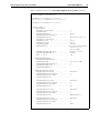
show bridge
Syntax
Description
SHow BRIDge
The output of this command includes a new field (Figure 5, Table 3).
Figure 5: Example output from the show bridge command
Remote Bridge
-----------------------------------------------------------Bridge Address
: 00-00-cd-00-0d-4d
Bridge Name
: Example version 2.7.6-00 1 May 2006
Spanning Tree Protocol
: ON
Filter Learning
: ON
Number LAN Ports
: 2
Port Number
: 1
Port Address
: 00-00-cd-00-0d-4d
CAM
: Enabled
Port Number
: 2
Port Address
: 00-00-cd-00-0d-82
CAM
: Enabled
Number of Virtual Ports : 1
Port Number
: 3
Number of Groups
: 1
Ageingtime
: 300
Uptime
: 12133
StripVlantag
: TRUE
------------------------------------------------------------
Table 3: New parameters in the output of the show bridge command
Parameter
Meaning
StripVlantag
Whether the bridge strips out the VLAN tag of tagged packets when it
receives them on Eth or VLAN interfaces and bridges them (“TRUE”), or
retains the VLAN tag (“FALSE”).
Software Version 2.9.1
C613-10486-00 REV C
Software Version 2.9.1
33
Internet Protocol (IP) Enhancements
This Software Version includes the following enhancements to IP:
■
Dynamic DNS Client
■
Preventing MAC Address Resolution Between Hosts Within a Subnet
■
IP Debug Timeout
■
Show IP Interface Command Displays Gratuitous ARP Status
This section describes the enhancements. The new and modified commands to
implement them are described in Command Reference Updates.
Dynamic DNS Client
Software Version 2.9.1 enables you to configure the router as a dynamic DNS
client, for operation with the service offered by DynDNS (see
www.dyndns.com/services/dns/). This feature is available on AR400 Series
routers and AR750S, AR750S-DP, and AR770S routers.
The dynamic DNS client allows you to associate the router’s public IP address
with up to five “hostnames” (FQDNs) registered with DynDNS.com. When the
router’s public IP address changes, the dynamic DNS client sends an HTTP
update to DynDNS.com, notifying them of the address change. DynDNS.com
then associates the new IP address with your registered hostnames, and
propagates this change through the DNS system.
This means that you can host servers behind the router’s public IP address
without actually owning your own domain name, and even if your public IP
address changes periodically.
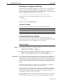
Configuring Dynamic DNS
To configure dynamic DNS, perform the following steps:
1.
Register with DynDNS.com and select a domain name to use
2.
Enable dynamic DNS, by using the command:
enable ddns
3.
Specify the hostname, interface, username, and password for the client to
use, and other options if required, by using the command:
set ddns [server=server] [port=port] [user=userid]
[password=password] [dynamichost=hostnames]
[customhost=hostnames] [statichost=hostnames]
[primaryint=interface] [secondaryint=interface]
[wildcard={on|off|nochg}]
[mailexchanger={mailexchanger|nochg}]
[backmx={yes|no|nochg}] [offline={yes|no}]
4.
Check that the client is correctly sending updates, by using the command:
show ddns
For a detailed step-by-step example and troubleshooting tips, see How To Use
Dynamic DNS To Allow You To Host Servers Behind A Dynamically-Assigned Public
IP Address. This How To Note is available in the Resource Center of the
Documentation and Tools CDROM for Software Version 2.9.1, or from
www.alliedtelesis.co.uk/site/solutions/techdocs.asp?area=howto.
Software Version 2.9.1
C613-10486-00 REV C
34
Internet Protocol (IP) Enhancements
Release Note
Command Changes
The following table summarises the new commands:
Command
Change
activate ddns update
New command
disable ddns
New command
disable ddns debug
New command
enable ddns
New command
enable ddns debug
New command
set ddns
New command
show ddns
New command
Preventing MAC Address Resolution Between Hosts
Within a Subnet
A new feature lets you stop MAC address resolution between hosts within an
interface’s subnet. Local proxy ARP ensures that devices within a subnet
cannot send traffic that bypasses the router or switch. This lets you monitor,
filter, and control traffic between devices in the same subnet.
Local proxy ARP extends proxy ARP by intercepting and responding to ARP
requests between hosts within a subnet. It responds to the ARP requests with
the router or switch’s own MAC address details instead of those from the
destination host. This stops hosts from learning the MAC address of other
hosts within its subnet.
When local proxy ARP is operating on an interface, the router or switch does
not generate or forward any ICMP-Redirect messages on that interface.
To create an interface that uses local proxy ARP, use the command:
add ip interface=interface ipaddress={ipadd|dhcp}
proxyarp=local [other-options]
To change an interface to use local proxy ARP, use the command:
set ip interface=interface ipaddress={ipadd|dhcp}
proxyarp=local [other-options]
Command Changes
The following table summarises the modified commands:
Command
Change
add ip interface
New local option for proxyarp parameter
set ip interface
New local option for proxyarp parameter
show ip interface
Existing proxyarp field displays the setting of the local
option
Software Version 2.9.1
C613-10486-00 REV C
Software Version 2.9.1
35
IP Debug Timeout
This enhancement makes it possible to specify a timeout value when enabling
IP debugging. After the timeout expires, IP debugging is automatically
disabled. This helps to prevent problems from too much IP debugging clogging
up the display.
To specify the timeout, use the new optional timeout parameter in the
command:
enable ip debug={all|arp|packet|advertise|upnp}
[timeout={none|1..2400}]
The timeout units are seconds.
For example, to enable ARP debugging and display the debugging information
for the next 25 seconds, use the command:
enable ip debug=arp timeout=25
To see the current timeout value, use the show debug active[=ip] command.
The current timeout is shown above the types of IP debugging that are
currently enabled (Figure 7 on page 43).
Command Changes
The following table summarises the modified commands:
Command
Change
enable ip debug
New timeout parameter
show debug active
New IP Debug Timeout field
Show IP Interface Command Displays Gratuitous ARP
Status
This Software Version includes an additional field in the output in the show ip
interface command. This displays whether the interface accepts or rejects
gratuitous ARPs.
Gratuitous ARP packets are ARP messages that are not required for the
functioning of ARP (RFC 826). However, they are often sent by devices to aid
with early detection of IP conflicts and to keep ARP tables in other routers or
switches up to date. To configure whether an interface accepts or rejects these
messages, use the command:
set ip interface[=interface] gratuitousarp={off|on}
To see which interfaces on the router or switch accept gratuitous ARP request
or reply messages, use the command:
show ip interface[=interface]
Command Changes
The following table summarises the modified command:
Software Version 2.9.1
C613-10486-00 REV C
Command
Change
show ip interface
New GArp field in output
36
Internet Protocol (IP) Enhancements
Release Note
Command Reference Updates
This section describes each new command and the changed portions of
modified commands and output screens. For modified commands and output,
the new parameters, options, and fields are shown in bold.
activate ddns update
Syntax
Description
Examples
ACTivate DDNS UPdate
This command activates a Dynamic DNS update.
To force a router to send a Dynamic DNS update, use the command:
act ddns up
add ip interface
Syntax
Description
ADD IP INTerface=interface IPaddress={ipadd|DHCP}
[ADVertise={YES|NO}] [BROadcast={0|1}]
[DIRectedbroadcast={False|NO|OFF|ON|True|YES}]
[FILter={0..999|NONE}] [FRAgment={NO|OFF|ON|YES}]
[GRAtuitousarp={ON|OFF}] [GRE={0..100|NONE}]
[IGMPProxy={OFF|UPstream|DOWNstream}]
[INVersearp={ON|OFF}] [MASK=ipadd] [METric=1..16]
[MULticast={BOTH|NO|OFF|ON|RECeive|SENd|YES}]
[OSPFmetric=1..65534] [POLicyfilter={0..999|NONE}]
[PREferencelevel={-2147483648..2147483647|NOTDEFAULT}]
[PRIorityfilter={0..999|NONE}]
[PROxyarp={DEFRoute|False|LOCal|NO|OFF|ON|STrict|True|
YES}] [RIPMetric=1..16] [SAMode={Block|Passthrough}]
[VJC={False|NO|OFF|ON|True|YES}]
[VLANPRiority={0..7|None}] [VLantag={1..4094|None}]
The new local option for proxyarp increases the range of ARP Requests that
the router or switch responds to. When you specify yes, on, true or strict, the
router or switch only responds to ARP Requests with a specific route if it exists,
and ignores all others. When you specify local, the router or switch responds
for routes it has a specific route to, and routes within its local subnet that
would normally be IGMP redirected. By intercepting and responding to these
local ARP requests, the router or switch prevents hosts within the subnet from
successfully using MAC address resolution to communicate directly with one
another. Instead, traffic between hosts is forwarded through the router or
switch.
Software Version 2.9.1
C613-10486-00 REV C
Software Version 2.9.1
37
disable ddns
Syntax
Description
Example
DISable DDNS
This command disables the Dynamic DNS feature.
To disable the DDNS feature, use the command:
dis ddns
disable ddns debug
Syntax
Description
Example
DISable DDNS DEbug
This command disables the Dynamic DNS debug facility.
To disable DDNS debugging, use the command:
dis ddns de
enable ddns
Syntax
Description
Example
ENAble DDNS
This command enables the Dynamic DNS feature.
To enable the DDNS feature, use the command:
ena ddns
enable ddns debug
Syntax
Description
Example
ENAble DDNS DEBug
This command enables the Dynamic DNS debug facility.
To enable DDNS debugging, use the command:
ena ddns deb
Software Version 2.9.1
C613-10486-00 REV C
38
Internet Protocol (IP) Enhancements
Release Note
enable ip debug
Syntax
Description
ENAble IP DEBug={ARP|PACket|ADVertise|UPNP|ALL}
[TIMEOut={NONE|1..2400}]
The new timeout parameter specifies the time period, in seconds, for which IP
debugging is enabled. Setting a timeout reduces the risk of overloading the
router or switch and the display with too much debugging information. The
value set by the timeout parameter overrides any previous IP debugging
timeout values, even if they were specified for other debugging options. The
default is the timeout value used the last time that this command was run, or
none.
To change the current timeout value, re-enter the command enable ip
debug={arp|packet|advertise|upnp|all} timeout={none|1..2400}. A value of
none turns the timeout off.
Note that you can also enter the command enable ip debug without specifying
an option on the debug parameter. This starts a different debugging mode, in
which IP stores the header and the reason for rejection of the 40 most recent
incorrectly formatted IP packets. You can then display the stored information
by using the show ip debug command. The new timeout parameter has no
effect when debugging is in this mode.
Examples
To display ARP debugging information for the next 25 seconds, use the
command:
enable ip debug=arp timeout=25
To enable all debug options indefinitely, use the command:
enable ip debug=all timeout=none
Software Version 2.9.1
C613-10486-00 REV C
Software Version 2.9.1
39
set ddns
Syntax
Description
SET DDNS [SERVER=server] [PORT=port] [USer=userid]
[PASSword=password] [DYNamichost=hostnames]
[CUSTomhost=hostnames] [STAtichost=hostnames]
[PRImaryint=interface] [SECOndaryint=interface]
[WILdcard={ON|OFF|NOCHG}]
[MAIlexchanger={mailexchanger|NOCHG}]
[BAckmx={YES|NO|NOCHG}] [OFFline={YES|NO}]
This command sets the parameters used for updating the Dynamic DNS.
Parameter
Description
SERVER
The name of the DDNS server. It is a string of up to 31 characters,
having a URL name format.
Default: members.dyndns.org
PORT
Specifies the remote port number to be used by a local HTTP client in
order to convey the Dynamic DNS Update. Only port numbers 80,
8245 and 443 can be used. Ports 80 and 8245 are for HTTP, and port
443 is for HTTPS. Port 8245 may be used to bypass transparent HTTP
proxies.
Default: 80
USer
A user name used for an account with Dynamic DNS. It may contain
up to 15 printable characters and is case sensitive. If the name
contains spaces, these must be enclosed in double quotes.
Default: no default.
PASSword
A password to be used with Dynamic DNS account. It may contain up
to 15 printable characters and is case sensitive. If the password
contains spaces, these must be enclosed in double quotes.
Default: no default.
DYNamichost
Host names to be used with Dynamic DNS. Each name may contain up
to 31 printable characters having a URL format. If a name contains
spaces, these must be enclosed in double quotes. Up to four comma
separated names can be entered. All names must be Internet
registered.
Defaults: no default.
CUSTomhost
Host names for Custom DNS. Each name may contain up to 31
printable characters having a URL format. If a name contains spaces,
these must be enclosed in double quotes. Up to four comma
separated names can be entered. All names must be Internet
registered.
Defaults: no default.
STAtichost
Host names to be used for Static DNS. Each name can be up to 31
printable characters long and is case sensitive. Up to four comma
separated names can be entered.
Default: no default.
PRImaryint
An interface to be used for the primary WAN connection. The IP
interface must be pre-defined.
Default: no default.
SECOndaryint
The interface to be used for the secondary WAN connection. The IP
interface must be pre-defined.
Default: no default.
Software Version 2.9.1
C613-10486-00 REV C
40
Internet Protocol (IP) Enhancements
Parameter (cont.)
WILdcard
Release Note
Description (cont.)
Whether to use the wildcard * feature when matching host names.
Default: off
MAIlexchanger
ON
Turns on the wildcard option.
OFF
Turns off the wildcard option.
NOCHG
Retains the previous wildcard value.
A mail exchanger to be used with the hostname. The mail exchanger
is a string of up to 31 characters.
Although the router or switch accepts any printable character string,
DynDNS requires a specific format such as a URL address.
Default: no default
mailexchanger
The mail exchanger name. It must be one that can be
resolved to an IP address or it is ignored.
By not providing a mail exchanger name or entering
one that does not resolve to an A record, you will
remove the record of the hostname.
NOCHG
BAckmx
Preserves the current mailexchanger setting.
Whether the mail exchanger specified by the mailexchanger
parameter is set up as a backup.
Default: no
OFFline
Yes
The mailexchanger is set as the backup.
No
The mailexchanger is not set as the backup.
NOCHG
Retains the existing setting.
Whether to set the hostnames to offline mode.
Default: no
Example
To set the DDNS operation for a user called Oliver, use the command:
set ddns us=oliver pas=fagin pri=ppp0
Software Version 2.9.1
C613-10486-00 REV C
Software Version 2.9.1
41
set ip interface
Syntax
Description
Software Version 2.9.1
C613-10486-00 REV C
SET IP INTerface=interface [ADVertise={YES|NO}]
[PREferencelevel={-2147483648..2147483647|NOTDEFAULT}]
[BROadcast={0|1}]
[DIRectedbroadcast={False|NO|OFF|ON|True|YES}]
[FILter={0..999|NONE}] [FRAgment={NO|OFF|ON|YES}]
[GRAtuitousarp={ON|OFF}] [GRE={0..100|NONE}]
[IGMPProxy={OFF|UPstream|DOWNstream}]
[INVersearp={ON|OFF}] [IPaddress=ipadd|DHCP]
[MASK=ipadd] [METric=1..16]
[MULticast={BOTH|OFF|ON|RECeive|SENd}]
[OSPFmetric=1..65534|DEFAULT]
[POLicyfilter={0..999|NONE}]
[PRIorityfilter={0..999|NONE}]
[PROxyarp={DEFRoute|False|LOCal|NO|OFF|ON|STrict|True|
YES}] [RIPMetric=1..16] [SAMode={Block|Passthrough}]
[VJC={False|NO|OFF|ON|True|YES}]
[VLANPRiority={0..7|None}] [VLantag={1..4094|None}]
The new local option for proxyarp increases the range of ARP Requests that
the router or switch responds to. When you specify yes, on, true or strict, the
router or switch only responds to ARP Requests with a specific route if it exists,
and ignores all others. When you specify local, the router or switch responds
for routes it has a specific route to, and routes within its local subnet that
would normally be IGMP redirected. By intercepting and responding to these
local ARP Requests, the router or switch prevents hosts within the subnet from
successfully using MAC address resolution to communicate directly with one
another. Instead, traffic between hosts is forwarded through the router or
switch.
42
Internet Protocol (IP) Enhancements
Release Note
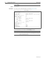
show ddns
Syntax
Description
SHow DDNS
This command displays information about DDNS configuration and operation
(Figure 6, Table 4 on page 42).
Figure 6: Example output from the show ddns command
DDNS Configure Information:
Client State ......................
Debug .............................
Server ............................
Port ..............................
User ..............................
Password ..........................
system name .......................
hosts ...........................
system name .......................
hosts ............................
MaileX ............................
Backmx ............................
Wildcard ..........................
Offline ...........................
Primary WAN Interface .............
Secondary WAN Interface ...........
ENABLED
DISABLED
members.dyndns.org
80
test
***
dyndns
test.dyndns.org
test.homeip.net
dyndns
test.custom.dyndns.org
test.custom.homeip.net
alliedtelesis.co.nz
no
off
no
vlan1
none
DDNS Operation Information:
Server IP ......................... 0.0.0.0
IP in DynDns ...................... 202.49.72.10
Current IP ........................ 202.49.72.10
Update failed - Suggested action:
Config IP DNS or Set DDNS Serve
Table 4: Parameters in output of the show ddns command
Parameter
Meaning
Client State
Whether the DDNS feature is enabled.
Debug
The DDNS debug state.
Server
The DDNS server name.
Port
The TCP or UDP port number being used for the DDNS
update. That is, the port that the packet is sent from.
system name
The DynDNS.com system that update messages use:
either dyndns, statdns, or custom, depending on the
type of hostname you chose. The router automatically
sets the system name to an appropriate value for your
hostname type.
hosts
A list of host names registered in this system, to be
resolved to the router’s public address.
MaileX
The name of the mail exchanger.
Backmx
Whether the MaileX is set as a backup mail exchanger.
Wildcard
Whether the wildcard (*) is used when matching host
name.
Software Version 2.9.1
C613-10486-00 REV C
Software Version 2.9.1
43
Table 4: Parameters in output of the show ddns command (cont.)
Parameter
Meaning
Offline
Whether the hostnames are set to offline mode.
Refer to the DynDNS website for offline redirection
options, available at:
http://www.dyndns.com/services/dns/dyndns/faq.html
Primary WAN Interface
The IP interface used for the main WAN connection.
Secondary WAN Interface
The IP interface used for the backup WAN connection.
Server IP
The IP address of Dynamic DNS server resolved by DNS.
IP in DynDns
The IP address assigned to the listed host names at the
last update.
Current IP
The latest IP address assigned to local WAN connection.
Update Failed - Suggested action
User action to take if the last update failed.
show debug active
Syntax
Description
SHow DEBug ACTIve={ALL|module}
For IP debugging, this command now displays the value of the IP debugging
timeout (Figure 7).
Figure 7: Example output from the show debug active=ip command
IP
---------------------------------------------------------IP Debug Timeout: 30 seconds
IP Debug Options Enabled:
IP Packet
IP ARP
Software Version 2.9.1
C613-10486-00 REV C
44
Internet Protocol (IP) Enhancements
Release Note
show ip interface
Syntax
Description
SHow IP INTerface[=interface] [COUnter[=MULticast]]
This command displays interface configuration information for interfaces
assigned to the IP module with the add ip interface command. The new GArp
field displays whether or not the interface accepts gratuitous ARPs. The PArp
field now displays Loc when local proxy ARP is enabled on the interface.
Figure 8: Example output of the show ip interface command from an AT-8600 Series switch
Interface
Type
IP Address
Bc Fr PArp Filt RIP Met.
Pri. Filt
Pol.Filt Network Mask
MTU
VJC
GRE OSPF Met. DBcast Mul.
GArp
-------------------------------------------------------------------------------LOCAL
Not Set
- n Def
--- ---------- --On
Loopback
192.168.10.100
- n --- --------- --On
vlan2
Static
192.168.1.1
1 n Loc
--- 01
Pass
No
----255.255.255.0
1500 --- 0000000001 No
Rec
On
vlan3#
Static
192.168.2.1
1 n Loc
--- 01
Pass
No
----255.255.255.0
1500 --- 0000000001 No
Rec
Off
--------------------------------------------------------------------------------
Table 5: New and modified parameters in the output of the show ip interface command
Parameter
Meaning
PArp
Whether this interface supports proxy ARP and if ARP responses will be
generated if a default route exists; one of “On” (respond to ARP Requests
only if a specific route exists), “Loc” (responds to ARP Requests if a specific
route exists, including ARP requests for hosts within a subnet) “Off”, or
“Def” (respond to ARP Requests if a specific route or a default route
exists).
GArp
Whether the interface accepts or rejects gratuitous ARP messages; one of
“On” or “Off”.
Software Version 2.9.1
C613-10486-00 REV C
Software Version 2.9.1
45
DHCP Enhancements
This Software Version includes the following enhancement to DHCP:
■
DHCP Options
This section describes the enhancement. The new and modified commands to
implement it are described in Command Reference Updates.
DHCP Options
Software Version 2.9.1 introduces the ability to create user-defined DHCP
options and apply them to policies.
DHCP allows the client to receive options from the DHCP server. Options
describe the network configuration, and various services that are available on
the network.
Previously, you could only add standard, pre-defined options to policies, using
the add dhcp policy command. Now, you can also add user-defined options,
using the new add dhcp option command.
Command Changes
The following table summarises the new and modified commands:
Command
Change
add dhcp option
New command
delete dhcp option
New command
set dhcp option
New command
show dhcp policy
New option values in display output
Command Reference Updates
This section describes each new command and the changed portions of
modified commands and output screens. For modified commands and output,
the new parameters, options, and fields are shown in bold.
add dhcp option
Syntax
Description
ADD DHCP OPTion=number POLIcy=name [NAMe=option-name]
TYpe={IP|SWItch|VALue|STRing|HexString|NONE}
VALue=value
This new command allows you to create a user-defined option for the specified
policy. User-defined options are outside the standard range of pre-defined
options that you can define using the add dhcp policy command.
It is possible to add a user-defined option with the same number as an existing
pre-defined option. If this situation occurs, the user-defined option takes
precedence - that is, it overrides but does not eliminate the pre-defined option.
Software Version 2.9.1
C613-10486-00 REV C
46
DHCP Enhancements
Release Note
Parameter
Description
OPTion
A number for the option. number is a decimal number between 1
and 254.
POLIcy
The name of the policy to add the option to. name is a character
string 1 to 15 characters long. Any printable character is allowed.
When you enter a name that contains spaces, you must surround it
with double quotation marks.
NAMe
Use this optional parameter to define a name for the option.
option-name is a character string 1 to 15 characters long. Any
printable character is allowed. When you enter an option-name that
contains spaces, you must surround it with double quotation marks.
TYpe
Use this optional parameter to specify a format in which to define the
value parameter.
Default: none
VALue
Examples
TYpe
Value format
IP
One or more IPV4 addresses in dotted decimal
format, separated by commas.
SWItch
Any of: on, off, yes, no, true, false, enabled,
disabled.
VALue
A decimal number between 0 and 4294967295.
STRing
A character string from 1 to 255 characters long.
Any printable character is allowed. When you
enter a string that contains spaces, you must
surround the string with double quotation marks.
HexString
A string of 1 to 255 sets of hexadecimal character
pairs; a maximum of 510 characters. The 510
character maximum includes any blank spaces or
quotes used.
NONE
No value is required.
value is a user-defined value, which you must enter in the format
specified with the type parameter - see above for details.
To add option 151 to the “base” policy with the name “svpserver”, and a type
of ip, use the command:
add dhcp opt=151 poli=base nam=svpserver ty=ip
val=192.168.3.3
To add option 114 to the “base” policy with no name, and a type of string, use
the command:
add dhcp opt=114 poli=base ty=str
val=http://allied-telesis.com
Software Version 2.9.1
C613-10486-00 REV C
Software Version 2.9.1
47
delete dhcp option
Syntax
Description
DELete DHCP OPTion=number POLIcy=name
This new command deletes a user-defined option from the specified policy.
User-defined options are created with the add dhcp option command.
It is possible for the same option number to be specified for different options,
one using add dhcp option and one using add dhcp policy. This command
only deletes the option created with add dhcp option.
To completely delete the option number from the system, you must also delete
the option with the same number that was created with add dhcp policy. You
can do this using the delete dhcp policy command.
Once this option is deleted, any existing pre-defined option with the same
option number becomes the active option.
Example
Parameter
Description
OPTion
The number of the option to delete. This option must have been
defined using add dhcp option. number is a decimal number
between 1 and 254.
POLIcy
The name of the policy that the option is attached to. name is a
character string 1 to 15 characters long. It may contain any printable
character. When you enter a name that contains spaces, you must
surround it with double quotation marks.
To delete option 151 from the “base” policy, use the command:
del dhcp opt=151 poli=base
set dhcp option
Syntax
Description
SET DHCP OPTion=number POLIcy=name [NAMe=option-name]
[TYpe={IP|SWItch|VALue|STRing|HexString|NONE}]
[VALue=value]
This new command allows you to modify an existing user-defined option on
the specified policy. User-defined options are created using add dhcp option.
You can modify the values set for the name, type, and value parameters. You
cannot change the policy to which the option applies.
Software Version 2.9.1
C613-10486-00 REV C
48
DHCP Enhancements
Release Note
Parameter
Description
OPTion
The number of the user-defined option to modify. number is a decimal
number between 1 and 254.
POLIcy
The policy to which the option applies. name is a character string 1 to
15 characters long. Any printable character is allowed. When you
enter a name that contains spaces, you must surround it with double
quotation marks.
NAMe
Use this optional parameter to set a new name for the option.
option-name is a character string 1 to 15 characters long. Any
printable character is allowed. When you enter an option-name that
contains spaces, you must surround it with double quotation marks.
TYpe
Use this optional parameter to specify a format in which to define the
value parameter.
If you specify a type, the value parameter is mandatory.
Default: none
VALue
TYpe
Value format
IP
One or more IPV4 addresses in dotted decimal format,
separated by commas.
SWItch
Any of: on, off, yes, no, true, false, enabled,
disabled.
VALue
A decimal number between 0 and 4294967295.
STRing
A character string from 1 to 255 characters long. Any
printable character is allowed. When you enter a
string that contains spaces, you must surround the
string with double quotation marks.
HexString
A string of 1 to 255 sets of hexadecimal character
pairs; a maximum of 510 characters. The 510
character maximum includes any blank spaces or
quotes used.
NONE
No value is required.
value is a user-defined value, which you must enter in the format
specified with the type parameter - see above for details.
If you specify a value, the type parameter is mandatory.
Examples
To set a new name of “server1” for option 151 on the “base” policy, use the
command:
set dhcp opt=151 poli=base nam=server1
To change the IP address for the user-defined option 151 on the “base” policy
to 192.168.3.2, use the command:
set dhcp opt=151 poli=base ty=ip value=192.168.3.2
Software Version 2.9.1
C613-10486-00 REV C
Software Version 2.9.1
49
show dhcp policy
Syntax
Description
SHow DHCP POLIcy[=name]
This command displays information about currently defined policies and the
options configured for them. If you specify a policy name, then information
about that policy is displayed only.
Figure 9: Example output from the show dhcp policy command
DHCP Policies
Name: pol1
Base Policy: none
01 subnetmask ....
03 router ........
06 dnsserver .....
51 leasetime .....
*151 SVP server ....
255.255.255.0
202.36.163.21
192.168.100.50
3600
192.168.88.20
Name: prnt
Base Policy: pol1
01 subnetmask .... (pol1)
03 router ........ (pol1)
06 dnsserver ..... (pol1)
51 leasetime ..... (prnt)
*151 SVP server .... (pol1)
*161 ............... (prnt)
*172 privservernum...(prnt)
*253 optionpresent...(prnt)
*254 privservernam15.(prnt)
192.168.100.33
255.255.255.0
202.36.163.21
192.168.100.50 192.168.100.33
infinity
(none)
192.168.4.2 192.168.6.2
4
(none)
privateserver
Table 6: Modified parameters in the output of the show dhcp policy command
Parameter
Description
options...
A list of the options configured for the specified policy.
Each entry includes the following information:
The DHCP option identifier. This is the number that was assigned to the
option.
The number now has an asterisk (*) on its left if its option is a user-defined
option, configured using the new add dhcp option command.
The parameter keyword. This is now either:
the default assigned name for an option between the numbers of 1-68
that was configured using add dhcp policy, or
a name that was user-defined for the option using the new add dhcp
option command.
The current values of the option. If the option was configured using the
new add dhcp option command then the option value is formatted based
on the specified type.
Example
To display information about the “base” policy, use the command:
sh dhcp poli=base
Software Version 2.9.1
C613-10486-00 REV C
50
DHCP Snooping Enhancements
Release Note
DHCP Snooping Enhancements
This Software Version includes the following enhancements to DHCP
snooping:
■
Adding Default Access Routers to Static Entries
■
Filtering Broadcast and Multicast Packets
This section describes the enhancements. The new and modified commands to
implement them are described in Command Reference Updates.
Adding Default Access Routers to Static Entries
You can now specify the access routers for a static entry. This allows DHCP
snooping to create a static entry for use in conjunction with MAC-Forced
Forwarding. To do this, use the router parameter in the command:
add dhcpsnooping binding[=macaddr] interface=vlan ip=ipadd
port=port-number router=ipadd,ipadd...
Adding a MAC address to the static entry is no longer compulsory. Instead, the
static entry is primarily identified by the IP address. For static DHCP entries
without a MAC address defined, ARP security compares only the IP address
details.
To delete a static entry, you must specify the IP address of the static entry using
the new ip parameter in the command:
delete dhcpsnooping binding ip=ipadd
For more information about MAC-Forced Forwarding, see the MAC-Forced
Forwarding chapter at the end of this Release Note.
Command Changes
The following table summarises the modified commands:
Command
Change
add dhcpsnooping binding
New router parameter
Modified binding parameter
delete dhcpsnooping binding
New ip parameter
Software Version 2.9.1
C613-10486-00 REV C
Software Version 2.9.1
51
Filtering Broadcast and Multicast Packets
For AT-8600, AT-8700XL, AT-8800, and Rapier Series switches, you can now
enhance DHCP snooping filtering so that the switch drops multicast and
broadcast packets sent from a client, except for:
■
ARP packets
■
IGMP Replies and IGMP Leaves packets, when IGMP snooping is enabled
■
DHCP packets, when DHCP snooping is enabled
To enable this filtering, use the command:
enable dhcpsnooping strictunicast
To disable strict unicast filtering, use the command:
disable dhcpsnooping strictunicast
For the AT-8948, x900-48, and AT-9900 Series switches, DHCP filtering works
in conjunction with QoS and Classifiers. The enable dhcpsnooping
strictunicast command causes the switch to drop IGMP packets sent from a
client, except for IGMP Replies and IGMP Leaves packets when IGMP
snooping is enabled.
To enable this filtering, use the command:
enable dhcpsnooping strictunicast
To filter other multicast and broadcast packets, and stop the switch’s hardware
from forwarding IGMP packets, you must configure QoS using the create qos
policy command, and classifiers using the create classifier command.
To disable strict unicast filtering, use the command:
disable dhcpsnooping strictunicast
Command Changes
The following table summarises the new commands:
Software Version 2.9.1
C613-10486-00 REV C
Command
Change
disable dhcpsnooping strictunicast
New command
disable dhcpsnooping strictunicast
New command
52
DHCP Snooping Enhancements
Release Note
Command Reference Updates
This section describes each new command and the changed portions of
modified commands and output screens. For modified commands and output,
the new parameters, options, and fields are shown in bold.
add dhcpsnooping binding
Syntax
ADD DHCPSnooping BINDing[=macaddr] INTerface=vlan IP=ipadd
POrt=port-number [ROUter=ipadd,ipadd...]
Description
This command adds a static entry to the DHCP snooping binding database.
The new router parameter allows you to specify the default access routers for
the static entry.
Example
Parameter
Description
BINDing
The MAC address of the client. Specifying a MAC address is now
optional.
ROUter
An optional comma separated list of IP addresses that gives the default
access routers for this client. Use this parameter if adding a DHCP
snooping binding for use in conjunction with MAC-Forced Forwarding.
To add a static DHCP snooping entry for a client with the IP address
192.168.12.101, on port 6 of vlan101, that has access to two access routers with
the IP addresses 66.105.1.2 and 66.105.1.4, use the command:
add dhcps bind int=vlan101 ip=192.168.12.101 po=6
rou=66.105.1.2,66.105.1.4
delete dhcpsnooping binding
Syntax
Description
Example
DELete DHCPSnooping BINDing IP=ipadd
This command deletes a dynamic or static entry from the DHCP snooping
binding database. The new ip parameter specifies the IP address of the
database entry to delete, in dotted decimal notation. You no longer need to
specify the MAC address of the static entry to delete it.
To delete a DHCP snooping entry for a client with the IP address
192.168.12.101, use the command:
del dhcps bind ip=192.168.12.101
Software Version 2.9.1
C613-10486-00 REV C
Software Version 2.9.1
53
disable dhcpsnooping strictunicast
Syntax
Description
DISable DHCPSnooping STRictunicast
This new command disables strict unicast filtering on DHCP snooping clients.
To use this command, DHCP snooping must be disabled.
On AT-8600, AT-8700XL, AT-8800, and Rapier Series switches, this restarts
normal forwarding of multicast and broadcast packets sent by clients to
devices further upstream.
On AT-8948, x900-48, and AT-9900 Series switches, this restarts normal
forwarding of IGMP packets sent by clients to devices further upstream. To
fully disable strict unicast filtering, you must disable any configured QoS and
classifiers dealing with IGMP packets that are attached to the untrusted ports.
Example
To disable strict unicast filtering on DHCP snooping clients, use the command:
dis dhcps str
enable dhcpsnooping strictunicast
Syntax
Description
ENable DHCPSnooping STRictunicast
This new command enables strict unicast filtering on DHCP snooping clients.
To use this command, DHCP snooping must be disabled.
When enabled on AT-8600, AT-8700XL, AT-8800, and Rapier Series switches,
the switch drops multicast and broadcast packets sent from a client, except for:
■
ARP packets
■
IGMP Replies and IGMP Leaves packets, when IGMP snooping is enabled
■
DHCP packets, when DHCP snooping is enabled
This ensures a client cannot flood other network devices using broadcast or
multicast packets.
When enabled on AT-8948, x900-48, and AT-9900 Series switches, the switch
drops IGMP packets, except for IGMP Replies and IGMP Leaves when IGMP
snooping is enabled.
This ensures that a client cannot flood network devices using IGMP queries.
Use this command in conjunction with QoS and Classifiers commands. To stop
other broadcast and multicast packets, you must configure QoS using the
create qos policy command, and classifiers using the create classifier
command.
Example
To enable strict unicast filtering on DHCP snooping clients, use the command:
en dhcps str
Software Version 2.9.1
C613-10486-00 REV C
54
MAC-Forced Forwarding
Release Note
MAC-Forced Forwarding
This Software Version adds support for MAC-Forced Forwarding.
MAC-Forced Forwarding provides a method for subscriber separation on a
network. It is appropriate for IPv4 Ethernet based networks, where a layer 2
bridged segment separates downstream clients from their upstream IPv4
gateways. It offers:
■
the ability to monitor, filter, and police any traffic between separate clients
within the same subnet
■
efficient use of limited resources
■
greater security within the subnet
For information and command syntax, see the MAC-Forced Forwarding chapter
found at the end of this document.
Software Version 2.9.1
C613-10486-00 REV C
Software Version 2.9.1
55
IP Multicasting Enhancements
This Software Version includes the following enhancements to IP Multicasting:
■
PIM Support on AT-8600 Series Switches
■
Query Solicitation
This section describes the enhancements. The new and modified commands to
implement them are described in Command Reference Updates.
PIM Support on AT-8600 Series Switches
This Software Version introduces Protocol Independent Multicast (PIM) on the
AT-8600 Series switches. For information about configuring PIM on your
switch, see the IP Multicasting chapter at the end of this Release Note.
When running Software Version 2.9.1 on an AT-8600 Series switch, you will
need a special feature licence to use PIM. Contact your authorised Allied
Telesis distributor or reseller for details and passwords of feature licences.
Query Solicitation
This Software Version enhances IGMP snooping by providing the new query
solicitation feature. Query solicitation minimises loss of multicast data after a
topology change on networks that use EPSR or spanning tree (STP, RSTP, or
MSTP) for loop protection.
When IGMP snooping is enabled and EPSR or Spanning Tree changes the
underlying link layer topology, this can interrupt multicast data flow for a
significant length of time. Query solicitation prevents this by monitoring for
any topology changes. When it detects a change, it generates a special IGMP
Leave message known as a Query Solicit, and floods the Query Solicit message
to all ports in every VLAN that query solicitation is enabled on. When the
IGMP Querier receives the message, it responds by sending a General Query,
which all IGMP listeners respond to. This refreshes snooped group
membership information in the network.
Query solicitation functions by default (without you enabling it) on all VLANs
on the root bridge in an STP instance and on all data VLANs on the master
node in an EPSR instance. By default, the root bridge or master node always
sends a Query Solicit message when the topology changes.
If you have multiple STP or EPSR instances, query solicitation only sends
Query Solicit messages on VLANs in the instance that experienced a topology
change.
In switches other than the STP root bridge or EPSR master node, query
solicitation is disabled by default, but you can enable it by using the command:
set igmpsnooping vlan={vlan-name|1..4094|all}
querysolicit={on|yes|true}
If you enable query solicitation on a switch other than the STP root bridge or
EPSR master node, both that switch and the root or master send a Query Solicit
message.
Software Version 2.9.1
C613-10486-00 REV C
56
IP Multicasting Enhancements
Release Note
Once the Querier receives the Query Solicit message, it sends out a General
Query and waits for responses, which update the snooping information
throughout the network. If necessary, you can reduce the time this takes by
tuning the IGMP timers, especially the queryresponseinterval parameter. For
more information, see the “IGMP Timers and Counters” section of How To
Configure IGMP on Allied Telesyn Routers and Switches for Multicasting. This How
To Note is available in the Resource Center of the Documentation and Tools
CDROM for Software Version 2.8.1, or from
www.alliedtelesis.co.uk/en-gb/solutions/techdocs.asp?area=howto
Disabling Query Solicitation and Display Settings
On switches other than the STP root bridge or EPSR master node, you can
disable query solicitation by using the command:
set igmpsnooping vlan={vlan-name|1..4094|all}
querysolicit={off|no|false}
To see whether query solicitation is on or off, use the command:
show igmpsnooping
Check the new Query Solicitation field.
Changes to IGMP Snooping Fast Leave Command Syntax
The command syntax for the Fast Leave feature has also been changed, to make
it more like the syntax for the query solicitation feature.
To enable Fast Leave on a specific VLAN, or all VLANs on the switch, the new
syntax is:
set igmpsnooping vlan={vlan-name|1..4094|all}
fastleave={on|yes|true}
To disable Fast Leave on a specific VLAN, or all VLANs on the switch, the new
syntax is:
set igmpsnooping vlan={vlan-name|1..4094|all}
fastleave={off|no|false}
The original syntax was:
set igmpsnooping fastleave={on|yes|true|off|no|false}
[interface=vlan]
This original syntax is still valid, but we recommend using the new syntax
instead.
Command Changes
The following table summarises the new and modified commands:
Command
Change
set igmpsnooping vlan
New command
show igmpsnooping
New Query Solicitation field
Software Version 2.9.1
C613-10486-00 REV C
Software Version 2.9.1
57
Command Reference Updates
This section describes each new command and the changed portions of
modified commands and output screens. For modified commands and output,
the new parameters, options, and fields are shown in bold.
set igmpsnooping vlan
Syntax
SET IGMPSNooping VLAN={vlan-name|1..4094|ALL}
[Fastleave={ON|OFF|YES|NO|True|False}]
[QUErysolicit={OFF|NO|False|ON|YES|True}]
where vlan-name is a unique name from 1 to 32 characters. Valid characters are
uppercase and lowercase letters, digits, the underscore, and hyphen. The
vlan-name cannot be a number or all.
Description
This command enables or disables Fast Leave processing and the new query
solicitation feature for IGMP Snooping.
The vlan parameter specifies the VLAN on which the specified feature is to be
enabled or disabled. The default is all.
The fastleave parameter specifies whether Fast Leave processing is enabled or
disabled. If you specify on, yes or true then Fast Leave processing is enabled on
the specified VLAN or all VLANs. If you specify off, no or false then Fast
Leave processing is disabled on the specified VLAN or all VLANs. Note that
Fast Leave should not be configured on a port that has multiple hosts attached
because it may adversely affect multicast services to some hosts. The default is
off.
This command deprecates the following command, which is still valid:
set igmpsnooping fastleave={on|yes|true|off|no|false}
[interface=vlan]
The querysolicit parameter specifies whether query solicitation is enabled on
the specified VLANs. Query solicitation minimises loss of multicast data after a
topology change on networks that use EPSR or spanning tree (STP, RSTP, or
MSTP) for loop protection. When an EPSR or STP topology change occurs,
IGMP snooping sends a query solicit message out every VLAN that query
solicitation is enabled on. When the IGMP Querier receives the message, it
responds by sending a General Query, which all IGMP listeners respond to.
This refreshes snooped group membership information in the network. The
default is on for the root bridge in an STP topology and the master node in an
EPSR topology and off for other routers or switches.
Example
To enable IGMP Snooping Fast Leave processing on VLAN “vlan2”, use the
command:
set igmpsn vlan=vlan2 f=on
Software Version 2.9.1
C613-10486-00 REV C
58
IP Multicasting Enhancements
Release Note
show igmpsnooping
Syntax
SHow IGMPSNooping [VLAN={vlan-name|1..4094}]
where vlan-name is a unique name for the VLAN 1 to 32 characters long. Valid
characters are uppercase and lowercase letters, digits, the underscore, and the
hyphen.
Description
This command displays information about IGMP snooping on a VLAN or
VLANs (Figure 10, Table 7). This now includes the status of query solicitation.
Figure 10: Example output from the show igmpsnooping command
IGMP Snooping
----------------------------------------------------------Status ........................... Enabled
Disabled All-groups ports ........ None
Vlan Name (vlan id) .....
Fast Leave ..............
Static Router Ports .....
Query Solicitation ......
.
.
.
default (1)
On
None
Off
Table 7: New parameters in output of the show igmpsnooping command
Parameter
Meaning
Query Solicitation
Whether query solicitation is enabled on this VLAN.
Software Version 2.9.1
C613-10486-00 REV C
Software Version 2.9.1
59
OSPF Enhancements
This Software Version includes the following enhancement to OSPF:
■
Neighbour Retransmission List Debugging
This section describes the enhancement. The modified commands to
implement it are described in Command Reference Updates.
Neighbour Retransmission List Debugging
A new nrl debugging option has been added to OSPF, to show additions to and
deletions from the neighbour retransmission list. To enable NRL debugging,
use the command:
enable ospf debug=nrl
Note that this option may generate large amounts of debugging output on a
large OSPF network. Use it with care.
To disable NRL debugging, use the command:
disable ospf debug=nrl
Command Changes
The following table summarises the modified commands:
Software Version 2.9.1
C613-10486-00 REV C
Command
Change
disable ospf debug
New nrl option for debug parameter
enable ospf debug
New nrl option for debug parameter
60
OSPF Enhancements
Release Note
Command Reference Updates
This section describes the changed portions of modified commands. The new
options are shown in bold.
disable ospf debug
Syntax
DISable OSPF DEBug={ALL|AUTOcost|IFSTate|LSU|NBRSTate|
NSSA|PACket|NRL|REDistribute|SPF|STAte}
Description
The option nrl has been added to the debug parameter. If you specify nrl,
neighbour retransmission list debugging is disabled.
enable ospf debug
Syntax
Description
ENAble OSPF DEBug={ALL|AUTOcost|IFSTate|LSU|NBRSTate|
NSSA|PACket|NRL|REDistribute|SPF|STAte}
[TIMEOut={NONE|1..2400}]
The option nrl has been added to the debug parameter. If you specify nrl, the
router or switch displays changes to the neighbour retransmission list. Note
that this option may generate large amounts of debugging output on a large
OSPF network. Use it with care.
Software Version 2.9.1
C613-10486-00 REV C
Software Version 2.9.1
61
BGP Enhancements
This Software Version includes the following enhancements to BGP:
■
Improved BGP Route Selection
■
Improved BGP Backoff Show Command Output
This section describes the enhancements. The modified commands to
implement them are described in Command Reference Updates.
Improved BGP Route Selection
This Software Version changes the preference order that BGP uses when
selecting a route based on the “route type” rule. The order of “route type”
preference is now:
1.
routes imported into the BGP routing table from the router’s RIB, using BGP
import or network entries
2.
routes learned through a BGP aggregate entry
3.
routes learned from a foreign peer of any type, such as an EBGP, IBGP or
confederation peer
Command Changes
This enhancement does not affect any commands.
Improved BGP Backoff Show Command Output
This Software Version includes the following improvements in the output of
the show bgp backoff command:
■
The output now has a field called "command status", which displays
“disabled” if the backoff feature has been manually disabled, or “enabled”
at all other times.
■
The field “backOff state” now displays “peer disabled” if you have enabled
BGP backoff but no peers yet exist.
Command Changes
The following table summarises the modified command:
Command
Change
show bgp backoff
New command status field
Modified backOff state field
Software Version 2.9.1
C613-10486-00 REV C
62
BGP Enhancements
Release Note
Command Reference Updates
This section describes the changed portions of modified output screens. The
new fields are shown in bold.
show bgp backoff
Syntax
Description
SHow BGP BACkoff
This command displays BGP backoff details (Figure 11, Table 8).
Figure 11: Example output of the show bgp backoff command
BGP Backoff Stats:
Stat
Value
---------------------------------command status
ENABLED
backOff state
PEER DISABLED
total hist backOffs
5
total backOffs
0
total backOff Limit
0
consecutive backOffs
0
consecutive backOffs limit
5
base Timeout
10
Timeout multiplier
100%
Timeout step
1
Timeout length (sec)
10
Mem Upper Threshold Value
95%
Mem Upper Notify
TRUE
Mem Lower Threshold Value
90%
Mem Lower Notify
FALSE
Current Mem use
84%
----------------------------------
Table 8: New and modified parameters in the output of the show bgp backoff command
Parameter
Meaning
command status
Overall status of the BGP backoff; either ENABLED or
DISABLED.
backOff state
The current status of BGP backoff.
NORMAL displays when BGP backoff is not active and
BGP is processing normally.
BACKED OFF displays when system memory use has
reached its upper threshold and BGP processing is
halted.
PEER DISABLED displays when the consecutive or total
backoff limits have been reached and the peers have
been disabled. This also displays if BGP backoff is
enabled, but no peer has yet been discovered.
DISABLED displays when the user has disabled backoff
functionality.
Software Version 2.9.1
C613-10486-00 REV C
Software Version 2.9.1
63
IPv6 Enhancements
This Software Version includes the following enhancements to IPv6:
■
Setting a Metric for RIPv6
■
Additional Show Command Filtering
This section describes the enhancements. The modified commands to
implement them are described in Command Reference Updates.
Setting a Metric for RIPv6
A new metric parameter lets you specify the cost to RIPv6 for crossing the
logical interface. This parameter is allowed only on link-local interfaces.
Therefore, setting this parameter also sets the metrics for all logical interfaces
over the same IPv6 interface to the same value.
To specify the cost to RIPv6 for crossing the logical interface, use the new
metric parameter in either of the commands:
create ipv6 interface=interface metric=1..16 [other-options]
set ipv6 interface=interface metric=1..16 [other-options]
For more information about RIPv6, see the Internet Protocol version 6 (IPv6)
chapter of your Software Reference.
Command Changes
The following table summarises the modified commands:
Command
Change
create ipv6 interface
New metric parameter
set ipv6 interface
New metric parameter
Additional Show Command Filtering
This Software Version includes the new full parameter for the command:
show ipv6 route [full]
The show ipv6 route full command displays all the routes in the IPv6 route
table. In previous software versions, the show ipv6 route command displayed
this. The show ipv6 route command now displays a subset of the routing table.
Command Changes
The following table summarises the modified command:
Command
Change
show ipv6 route
New full parameter
Command Reference Updates
This section describes the changed portions of the modified commands. The
new parameters are shown in bold.
Software Version 2.9.1
C613-10486-00 REV C
64
IPv6 Enhancements
Release Note
create ipv6 interface
Syntax
Description
CREate IPV6 INTerface=interface [DUPtrans=1..16]
[METric=1..16] [RETRans=0..4294967295]
This command creates an IPv6 Ethernet interface and uses stateless address
autoconfiguration to assign it a link-local address.
The new metric parameter specifies the cost to RIPv6 for crossing the logical
interface. This parameter is allowed only on link-local interfaces. Therefore,
setting this parameter also sets metrics for all logical interfaces over the same
IPv6 interface to the same value. The default is 1.
set ipv6 interface
Syntax
Description
SET IPV6 INTerface=interface [FILter=0..99]
[IPaddress=ipv6add/prefix-length] [METric=1..16]
[PREFerred=1..4294967295|INFinite]
[PRIorityfilter=200..299]
[PUBlish={YES|NO|ON|OFF|True|False}]
[VALid=1..4294967295|INFinite]
This command modifies values associated with an interface that was created
by either the create ipv6 interface or add ipv6 interface command.
The new metric parameter specifies the cost to RIPv6 for crossing the logical
interface. This parameter is allowed only on link-local interfaces. Therefore,
setting this parameter also sets the metrics for all logical interfaces over the
same IPv6 interface to the same value. The default is 1.
show ipv6 route
Syntax
Description
SHow IPV6 ROUte [FULL]
This command displays the contents of the IPv6 route table. The full parameter
displays all the routes in the IPv6 route table. When the full parameter is not
specified, then the command displays a subset of the routing table that
includes:
■
all static routes
■
all interface routes
■
only the RIP routes that are alive and best
Software Version 2.9.1
C613-10486-00 REV C
Software Version 2.9.1
65
Firewall Enhancements
This Software Version includes the following enhancements to Firewall:
■
Using Automatic Client Management to Manage SIP Sessions
■
Setting a Trigger for Automatic Client Management
■
Limiting Firewall Sessions from a Device
■
Monitoring Firewall Sessions using SNMP
■
Dynamic Renumbering of Firewall Rules
This section describes the enhancements. The new and modified commands to
implement them are described in Command Reference Updates.
Using Automatic Client Management to Manage SIP
Sessions
This Software Version allows you configure the SIP ALG to dynamically
manage SIP clients using the new automatic client management mode.
Automatic client management mode allows the SIP ALG to dynamically
manage SIP clients and reserve firewall sessions for registered SIP clients. The
SIP ALG does this by monitoring the messages sent by private SIP clients to
SIP Registrars, and creating sessions that match the registration details. The SIP
ALG also provides NAT when this is configured on the firewall.
For a VoIP phone to send and receive calls, it must register on the wider
network with a SIP Registrar. When a SIP client registers, the SIP Registrar
sends a response back to the SIP client informing the client of the expiry time
limit for the registration. The SIP ALG looks for these messages and records the
expiry time. It then makes sure that the firewall session created is retained until
the registration expires. This means that the client is reachable through the
firewall with the registered IP address and port for the entire duration of the
registration. This is different to normal firewall session behaviour, where
sessions are timed out and deleted if no traffic is seen for a certain time period.
Once registered, a SIP client can send and receive calls through a SIP Proxy
Server. Often the proxy server is on the same device as the SIP Registrar, and
uses the same firewall session created for the SIP Registrar. However, SIP
clients can send and receive calls from proxy servers that are independent from
the SIP Registrar.
When a proxy server is initiating a call to a SIP client, it uses the client’s IP
address and port details listed with the SIP Registrar. If the proxy server is on a
different device from the Registrar, and you have configured the SIP ALG
client management to allow calls from unknown proxy servers, then the SIP
ALG creates a new firewall session for the proxy server. This new session uses
the same global IP and port translation for the client that the firewall has
assigned for the Registrar session. When the client initiates a session with any
independent proxy server, the SIP ALG can also assign to the new session the
same global IP and port that the Registrar session has. This gives the client a
consistent identity on the public network.
Note that a private device may use the same global IP address and port
number to send registration messages for more than one SIP URI. If this occurs,
then the SIP ALG keeps the session open until all the registrations have
expired.
Software Version 2.9.1
C613-10486-00 REV C
66
Firewall Enhancements
Network address
translation
Release Note
In automatic mode, the SIP ALG uses NAT on the sessions when NAT has been
configured on the firewall. We recommend that you select enhanced NAT. In
automatic mode, the SIP ALG is designed to give each SIP client a consistent
identity on the public network when NAT is in use.
It is possible to use the SIP ALG without NAT. This is an option for networks
where the SIP clients have globally routable IP addresses, or the whole SIP
network is restricted to a privately addressed network.
Configuring the SIP ALG in automatic mode
This section describes how to configure the firewall so that VoIP calls are
managed using the SIP ALG in automatic mode. This includes configuring
enhanced NAT on the firewall policy.
Before you start
Procedure
This section describes the IP and firewall configuration. You also need to:
■
configure the underlying connection to the Internet, such as PPP or ADSL
■
create a security officer and enable system security, if required
Step Action
Commands
1
add ip interface=interface ipaddress=ipadd
[other-ip-parameters]
Configure IP on the public and
private interfaces:
assign IP addresses
create a default route on the
public interface, if required
add ip route=0.0.0.0 mask=0.0.0.0
interface=public-interface nexthop=ipadd
2
Enable IP.
enable ip
3
Enable the SIP ALG.
enable firewall sipalg
4
Create a firewall policy.
create firewall policy=name
[other-policy-parameters]
5
Use the policy on the router or
switch’s public and private
interfaces.
add firewall policy=name
interface=public-interface type=public
6
Configure the NAT mode for the
policy.
add firewall policy=name nat=enhanced
7
Configure the SIP ALG for the
firewall:
set firewall sipalg mode=automatic
[maxautoclients=1..1000]
[multiservers={outonly|off|on|yes}]
assign the mode
add firewall policy=name
interface=private-interface type=private
specify the maximum number
of automatic clients
specify how calls to and from
Proxy Servers are dealt with
8
Storing client
information
Enable the firewall.
enable firewall
In automatic mode, the SIP ALG stores the SIP client details in a client
database. This database contains the registration expiry times as well as client
information, and is stored both dynamically and statically. The dynamic
version is stored on RAM, while a static copy is stored on flash. The static copy
is designed to minimise any loss of service to SIP clients. If a router or switch
restart or reboot occurs, then the SIP ALG can immediately restore the firewall
sessions using the information in this file.
Software Version 2.9.1
C613-10486-00 REV C
Software Version 2.9.1
67
To show details about the flash file and the current client sessions that the SIP
ALG has, use the commands:
show firewall sipalg autoclients[=session-number] [summary]
show firewall sipalg autoclients ip=ipadd[-ipadd] [summary]
To delete the current details in the client database, use the command:
reset firewall sipalg autoclients
Resetting the database does not delete any established SIP sessions.
In an AR400 or AR700 Series router with the flash autowrite feature disabled,
the SIP ALG will not be able to create a static copy of the client database. To
enable this feature, use the command:
enable flash autowrite
If you disable flash autowrite while the SIP ALG is in automatic mode, then the
SIP ALG will no longer be able to write to the client database, but the file will
still remain on the flash. To delete the file, use the command:
delete file=fwsipmap.sip
Command Changes
The following table summarises the new and modified commands:
Command
Change
reset firewall sipalg autoclients
New command
set firewall sipalg
New mode parameter
New maxautoclients parameter
New multiservers parameter
show firewall sipalg
New Mode field in output
New Maximum automatic clients field in output
New Multiple servers field in output
show firewall sipalg autoclients
New command
Setting a Trigger for Automatic Client Management
This Software Version allows you to set a firewall trigger to run a script when
the SIP ALG reaches the limit for the number of SIP clients it can support in
automatic mode. To create the trigger, use the new sipautomax parameter in
the command:
create trigger=trigger-id firewall=sipautomax mode=start
[other-options]
To modify the trigger, use the command:
set trigger=trigger-id firewall=sipautomax mode=start
[other-options]
Software Version 2.9.1
C613-10486-00 REV C
68
Firewall Enhancements
Release Note
Command Changes
The following table summarises the modified commands:
Command
Change
create trigger
Modified firewall parameter
set trigger
Modified firewall parameter
Limiting Firewall Sessions from a Device
This Software Version allows you to limit the number of concurrent sessions a
device can initiate by using the new limitrule firewall commands. Limit rules
apply to firewall sessions initiated by a device on either side of the firewall, and
are attached to policies.
Each time a device initiates a session through the firewall, the router or switch
checks all the limit rules for the applicable firewall policy. If a session exceeds
the limit in a matching rule, then the router or switch does not allow the new
session to start. The device can only start the new session once it has ended one
or more of the current sessions. If a session does not match any limit rules, then
no limit is applied. Each policy can have up to 100 limit rules.
All matching existing session numbers are included when the router or switch
checks the limit rules and more than one limit rule can apply to a session.
However, if the firewall finds any matching rule that denies the session, then
the session is denied, regardless of the other rules.
To add a limit rule to a policy, use the new add firewall policy limitrule
command:
add firewall policy=policy-name limitrule=rule-id
srciplimit=0..10000 [interface=interface]
[gblremoteip=ipadd[-ipadd]] [ip=ipadd[-ipadd]]
The ip and gblremoteip parameters specify the IP address range of the private
(ip) and public (gblremoteip) devices that you are limiting the sessions for. The
limit is set with the srciplimit parameter, and is applied to each device
separately. That is, if a rule limits devices to 20 sessions, then any device can
initiate a maximum of 20 sessions regardless of the other devices’ activity.
Each limit rule applies to sessions initiated from both sides of the firewall. For
example, consider the command:
add firewall policy=policy-name limitrule=1 srclimit=3
[interface=interface] gblremoteip=125.4.10.1-125.4.10.12
ip=101.20.20.1
In the above example:
■
the private device (101.20.20.1) can initiate a maximum of three sessions to
all devices within the IP range 125.4.10.1 to 125.4.10.12
■
each public device within the specified range can initiate up to three
sessions each to the private device.
To modify a limit rule, use the new set firewall policy limitrule command:
set firewall policy=policy-name limitrule=rule-id
[interface=interface] [gblremoteip=ipadd[-ipadd]]
[ip=ipadd[-ipadd]] [srciplimit=0..10000]
Software Version 2.9.1
C613-10486-00 REV C
Software Version 2.9.1
69
These commands limit sessions only as they are created; new or modified limit
rules do not end any sessions already established by a device.
To delete a limit rule, use the new delete firewall policy limitrule command:
delete firewall policy=policy-name limitrule=rule-id
To display the limit rules set for a policy, use the new show firewall policy
limitrule command:
show firewall policy=policy-name
limitrule[=rule-id[-rule-id]] [detail]
The show firewall policy command has also been modified to show a
summary of the number of limit rules attached to a policy.
The firewall debugging feature has been enhanced to encompass the addition
of limit rules to the firewall. The enable firewall policy debug and disable
firewall policy debug commands now include the limitrule option for
displaying debugging related to limit rules.
Command Changes
The following table summarises the new and modified commands:
Command
Change
add firewall policy limitrule
New command
delete firewall policy limitrule
New command
disable firewall policy debug
New limitrule option for debug parameter
enable firewall policy debug
New limitrule option for debug parameter
set firewall policy limitrule
New command
show firewall policy
New Number of Limitrules field
show firewall policy limitrule
New command
Monitoring Firewall Sessions using SNMP
This Software Version allows you to use SNMP to monitor these firewall
session details:
■
the total number of sessions through the firewall
■
the number of current sessions that each private and public device has
established through the firewall
To monitor the number of current sessions that individual devices are using,
the firewall must generate a session report database. To enable the firewall to
generate this database, use the command:
enable firewall sessionreport
Note that there is a resource cost for the router or switch to maintain this
database, so session reporting is disabled by default.
To disable session reporting, use the command:
disable firewall sessionreport
Software Version 2.9.1
C613-10486-00 REV C
70
Firewall Enhancements
Release Note
The firewall Group of the Allied Telesis Enterprise MIB ({ enterprises(1)
alliedTelesis(207) mibObject(8) brouterMib(4) atRouter(4) modules(4) 77 }),
now includes firewallSessionsStatistics ({ firewall 2 }). This is a collection of
objects for monitoring firewall sessions:
■
totalNumberOfSessions ({ firewallSessionsStatistics 1 }) is the total number
of sessions going through the firewall. It is the sum of the number of
sessions on all individual nodes.
■
numberOfSessionsPerNodeCountingStatus ({ firewallSessionsStatistics 2 })
is the status of counting the number of sessions per node - enabled(1) or
disabled(2).
■
numberOfSessionsPerNodeTable ({ firewallSessionsStatistics 3 }) is a table
of nodes and number of sessions per node, indexed by IP address. It
contains the following objects:
•
nodeIpAddress, the IP address of a node that has firewall limit rules
attached and is being monitored.
•
numberOfSessionsPerNode, the number of active sessions created by
the corresponding node.
Command Changes
The following table summarises the new and modified commands:
Command
Change
disable firewall sessionreport
New command
enable firewall sessionreport
New command
show firewall
New SNMP Session Report field
Dynamic Renumbering of Firewall Rules
This Software Version dynamically renumbers firewall rules, so that you can
easily insert a new rule between two consecutive ones. For example, you can
now insert a new rule 2 on a policy with rules numbered 1, 2, 3, 7. The new rule
takes position 2 in the rule list, while the existing rule 2, and the rest of the rules
with numbers greater than 2, are renumbered and shuffled down the rule list
until a gap in the numbering scheme is found. The new rule list is numbered 1,
2, 3, 4, 7.
Note that the second instance of a particular rule number keeps that number,
not the first instance. This means that if you add a sequence of rules where two
rules have the same number, the first of these rules may become significantly
lower on the list. For example, if a configuration script has these rule numbers
in this sequence:
add
add
add
add
add
firewall
firewall
firewall
firewall
firewall
policy=policy-name
policy=policy-name
policy=policy-name
policy=policy-name
policy=policy-name
rule=1
rule=3
rule=3
rule=4
rule=5
then the first instance of rule 3 is eventually renumbered until it becomes rule
6. This occurs because the second rule 3 becomes rule 3 and renumbers the first
rule 3 to rule 4. Then the second rule 4 renumbers it to rule 5, and the second
rule 5 renumbers it to rule 6. The new list of rule numbers is 1, 3, 4, 5, 6.
Software Version 2.9.1
C613-10486-00 REV C
Software Version 2.9.1
71
Command Changes
This enhancement does not affect any commands.
Software Version 2.9.1
C613-10486-00 REV C
72
Firewall Enhancements
Release Note
Command Reference Updates
This section describes each new command and the changed portions of
modified commands and output screens. For modified commands and output,
the new parameters, options, and fields are shown in bold.
add firewall policy limitrule
Syntax
Description
ADD FIREwall POLIcy=policy-name LIMitrule=rule-id
[INTerface={interface}] [IP=ipadd[-ipadd]]
[GBLRemoteip=ipadd[-ipadd]] [SRCIplimit=0..10000]
This command adds a limit rule to a firewall policy. Limit rules apply a limit to
the number of concurrent sessions that a device can initiate through the
firewall. Each firewall policy can have up to 100 limit rules. The details for a
session must match all values set for the interface, ip, and gblremote
parameters for the limit rule to apply.
Each time a device initiates a session across the firewall, the router or switch
checks all the limit rules attached to a policy. If a session exceeds the limit in a
matching rule, then the router or switch does not allow the new session to start.
The device can only start the new session once it has ended one or more of the
current sessions.
This command only applies the limit as sessions are created; it does not end
any sessions established by the device before this rule was added. However, all
matching existing session numbers are included when the router or switch
checks the limit rules.
Parameter
Description
POLIcy
The policy that the rule is added to. The policy-name is a string 1 to
15 characters long. Valid characters are uppercase and lowercase
letters, digits (0–9), and the underscore character. The specified
policy must already exist.
LIMitrule
A numerical identifier for the rule for this policy. The rule-id is a
decimal number from 1 to 4294967295.
INTerface
The interface that the rule is applied to. The interface must already
exist and belong to the policy. Valid interfaces are:
eth (such as eth0, eth0-1)
VLAN (such as vlan1, vlan1-1)
FR (such as fr0, fr0-1)
X.25 (such as x25t0, x25t0-1)
PPP (such as ppp0, ppp1-1)
Alternatively, this may be a dynamic interface, formed by
concatenating the string “dyn-” with the name of a dynamic
interface template (e.g. dyn-remote).
Default: all interfaces attached to the policy
IP
IP address of the private device or range of devices you are limiting
the sessions for. Devices must be on the private side of the firewall.
The IP address is specified using dotted decimal notation.
Default: all private devices
Software Version 2.9.1
C613-10486-00 REV C
Software Version 2.9.1
73
Parameter
Description
GBLRemoteip
IP address of the public device or range of devices you are limiting
the sessions for. Devices must be on the public side of the firewall.
The IP address is specified using dotted decimal notation.
Default: all public devices
SCRIplimit
Number of sessions matching this rule that each device is allowed.
Default: 0 (no limit set)
Example
To limit all devices on the interface vlan2 to a maximum of 12 active sessions
per device, using the policy named “AT_Field”, use the command:
add fire poli=AT_Field lim=1 int=vlan2 srci=12
create trigger
Syntax
Description
CREate TRIGger=trigger-id
FIREwall={ALL|DOSattack|FRAgattack|HOStscan|PORtscan|
SESSION|SIPAutomax|SMTPATTACK|SMUrfattack|SYNattack|
TCPattack} [MODE={STArt|END|BOTH}] [AFTer=hh:mm]
[BEFore=hh:mm] [{DAte=date|DAYs=day-list}] [NAMe=name]
[REPeat={Yes|No|ONCe|FORever|count}]
[SCript=filename...] [STAte={ENAbled|DIsabled}]
[TEST={YES|NO|ON|OFF|True|False}]
This command creates a new trigger for the firewall and defines events and
conditions that activate it.
Firewall Event
Description
SIPAutomax
This trigger activates when the SIP ALG reaches the limit for the
number of SIP clients it can support in automatic mode. After this
trigger is first activated, further triggers are rate limited to once
every 20 minutes. The trigger will not activate again until at least
20 minutes have passed in which the limit is not exceeded.
Note that the firewall policy and source IP address script parameters
are not valid for this type of event. You can set the mode parameter
only to start for this trigger.
Example
To create trigger 6, which activates the script file fwsipmax.scp when the SIP
ALG has reached the limit of SIP clients it is configured to support in automatic
mode, use the command:
cre trig=6 fire=sipa mode=sta sc=fwsipmax.scp
Software Version 2.9.1
C613-10486-00 REV C
74
Firewall Enhancements
Release Note
delete firewall policy limitrule
Syntax
Description
Example
DELete FIREwall POLIcy=policy-name LIMitrule=rule-id
This command deletes a limit rule from the specified policy.
Parameter
Description
POLIcy
The policy you are deleting the rule from. The policy-name is a string
1 to 15 characters long. Valid characters are uppercase and
lowercase letters, digits (0–9), and the underscore character. The
specified policy must already exist.
LIMitrule
The numerical identifier for the rule you are deleting. The rule-id is a
decimal number from 1 to 4294967295.
To delete limit rule 1 from the policy named “EVA”, use the command:
del fire poli=EVA lim=1
disable firewall policy debug
Syntax
DISable FIREwall POLIcy[=policy-name]
DEBug={ALL|ARP|CHecksum|HTTP|IDentproxy|LIMitrule|
PACKet|PKT|PRocess|PROXy|RADius|SIPAlg|SMTP|TCP|UPNP}
[DEBUGMode={ALL|ERRORcode|MESSage|PARSing|TRAce}]
Description
This command disables debugging of the specified policy or all policies. The
new limitrule option for the debug parameter allows you stop the display of
debugging information related to limit rules.
Example
To stop displaying debugging of limit rules for all policies, use the command:
dis fire poli deb=lim
disable firewall sessionreport
Syntax
Description
Example
DISable FIREwall SESsionreport
This command stops the firewall from maintaining a database of the number of
firewall sessions that private and public devices use. SNMP reporting will no
longer have access to this database. Note that the there is a resource cost for the
router or switch to maintain this database, so session reporting is disabled by
default.
To stop the firewall from maintaining the session report for SNMP, use the
command:
dis fire ses
Software Version 2.9.1
C613-10486-00 REV C
Software Version 2.9.1
75
enable firewall policy debug
Syntax
ENable FIREwall POLIcy[=policy-name]
DEBug={ALL|ARP|CHecksum|HTTP|IDentproxy|LIMitrule|
PACKet|PKT|PRocess|PROXy|RADius|SIPAlg|SMTP|TCP|UPNP}
[DEBUGMode={ALL|ERRORcode|MESSage|PARSing|TRAce}]
IP=ipadd[-ipadd]
Description
This command enables debugging of the specified policy or all policies. The
new limitrule option for the debug parameter allows you to display
debugging information related to limit rules.
Example
To display debugging of limit rules for the “SEELE” policy, use the command:
en fire poli=SEELE deb=lim
enable firewall sessionreport
Syntax
Description
Example
ENAble FIREwall SESsionreport
This command enables the firewall to create a database that records individual
firewall sessions for SNMP reporting. The database monitors the number of
sessions created by private and public devices. Note that there is a resource
cost for the router or switch to maintain this database, so session reporting is
disabled by default.
To enable the firewall to create a session report that SNMP can access, use the
command:
ena fire ses
reset firewall sipalg autoclients
Syntax
Description
RESET FIREwall SIPAlg AUTOclients
This command deletes the SIP ALG’s current client database. The SIP ALG
generates this database when it is in automatic client management mode. This
command deletes both the dynamic version in RAM and the static version in
flash memory. Established SIP sessions are not affected.
Note that you can delete single automatic sessions using the delete firewall
session command. Use the show firewall sipalg autoclients command to
determine the session number.
Example
To reset the client details created by the SIP ALG in automatic mode, use the
command:
reset fire sipa auto
Software Version 2.9.1
C613-10486-00 REV C
76
Firewall Enhancements
Release Note
set firewall policy limitrule
Syntax
Description
SET FIREwall POLIcy=policy-name LIMitrule=rule-id
[INTerface={interface}] [IP=ipadd[-ipadd]]
[GBLRemoteip=ipadd[-ipadd]] [SRCIplimit=0..10000]
This command modifies a limit rule attached to a firewall policy. Limit rules
apply a limit to the number of concurrent sessions that a device can initiate
through the firewall. Each firewall policy can have up to 100 limit rules. The
details for a session must match all values set for the interface, ip, and
gblremote parameters for the limit rule to apply.
Each time a device initiates a session across the firewall, the router or switch
checks all the limit rules attached to a policy. If a session exceeds the limit in a
matching rule, then the router or switch does not allow the new session to start.
The device can only start the new session once it has ended one or more of the
current sessions.
This command only applies the limit as sessions are created; it does not end
any sessions established by a device before this rule was modified. However,
all matching existing session numbers are included when the router or switch
checks the limit rules.
Parameter
Description
POLIcy
The policy that the rule is added to. The policy-name is a string 1 to
15 characters long. Valid characters are uppercase and lowercase
letters, digits (0–9), and the underscore character. The specified
policy must already exist.
LIMitrule
A numerical identifier for the rule for this policy. The rule-id is a
decimal number from 1 to 4294967295. The specified rule must
already exist.
INTerface
The interface that the rule is attached to. The interface must already
exist and belong to the policy. Valid interfaces are:
eth (such as eth0, eth0-1)
VLAN (such as vlan1, vlan1-1)
FR (such as fr0, fr0-1)
X.25 (such as x25t0, x25t0-1)
PPP (such as ppp0, ppp1-1)
Alternatively, the interface may be a dynamic interface, formed by
concatenating the string “dyn-” with the name of a dynamic
interface template (e.g. dyn-remote).
Default: all interfaces attached to the policy
IP
IP address of the private device or range of devices you are limiting
the sessions for. Devices must be on the private side of the firewall.
The IP address is specified using dotted decimal notation.
Default: all private devices
GBLRemoteip
IP address of a public device or range of devices you are limiting the
sessions for. Devices must be on the public side of the firewall. The
IP address is specified using dotted decimal notation.
Default: all public devices
SCRIplimit
Number of sessions matching this rule that each device is allowed.
Default: 0 (no limit set)
Software Version 2.9.1
C613-10486-00 REV C
Software Version 2.9.1
Example
77
To modify limit rule 1 attached to vlan2 for the “Nerv_office” policy to match
IP address 202.36.164.113, use the command:
set fire poli=Nerv_office lim=1 int=vlan2 ip=202.36.164.113
set firewall sipalg
Syntax
Description
SET FIREwall SIPAlg
[CALLIdtranslation={False|NO|OFF|ON|True|YES}]
[MODe={MANual|AUTOmatic}] [MAXAutoclients=1..1000]
[MULTIservers={OUTOnly|False|NO|OFF|ON|True|YES}]
This command modifies how the SIP ALG operates on the router or switch.
The new mode, maxautoclients and multiservers parameters allow you to
configure automatic client management for the SIP ALG.
Parameter
Description
MODe
Whether the clients are managed automatically by the SIP ALG, or
manually using policy rules.
Default: manual
MAXAutoclients
MANual
You must configure policy rules for each VoIP client to
control their SIP sessions and provide NAT.
AUTOmatic
The SIP ALG automatically manages firewall sessions
for VoIP clients, and the firewall does not need policy
rules configured for SIP traffic. The SIP ALG provides
NAT for the clients by using the settings configured by
the add firewall policy nat command. The
recommended NAT setting is enhanced NAT.
The maximum number of SIP clients that the SIP ALG will support
when in automatic mode. Once the number of clients registered with
firewall sessions reaches this maximum, registrations by other SIP
clients are only permitted according to normal firewall behaviour or
any configured firewall rules. These excess client’s session details are
not stored in flash memory, and will age out based on the configured
udptimeout or udpporttimeout for the policy. This may interrupt
SIP sessions for these clients. Take care not to set maxautoclients to
a lower value than the current number of active clients registered,
because this may interrupt the SIP sessions.
This parameter is only valid when mode is set to automatic.
Default: 100
Software Version 2.9.1
C613-10486-00 REV C
78
Firewall Enhancements
Release Note
Parameter (cont.) Description (cont.)
MULTIservers
How the SIP ALG interacts with sessions initiated to and from SIP
Proxy Servers that are independent of the SIP Registrar. An
independent proxy server does not have the same IP or port details as
the SIP Registrar.
This parameter is only valid when mode is set to automatic.
Default: no
Example
OUTOnly
Sessions sent by a SIP client to independent proxy
servers are matched to the original session created
between the SIP client and the SIP Registrar. If NAT is
configured, then the translation is the same as the
original session between the SIP client and the
registrar. However, calls sent by proxy servers that do
not have an existing session with the SIP client and do
not have a matching allow rule are dropped.
False, NO,
OFF
A new firewall session is created for any calls to an
independent proxy server that the SIP client makes. If
NAT is configured, the translation does not match the
original session created between the SIP client and
the SIP Registrar. If no session currently exists
between the proxy server and the SIP client and there
is no matching allow rule for the server, any calls sent
by the proxy server are dropped.
ON, True,
YES
Sessions sent and received from independent proxy
servers are matched to the original session created
between the SIP client and the SIP Registrar. If NAT is
configured, then the translation is the same as the
original session between the SIP client and the
registrar. Calls from proxy servers that match the IP
and port details the client has registered with the SIP
Registrar are allowed through the firewall.
To enable the SIP ALG to automatically manage SIP clients on the private
network, allowing a maximum of 50 SIP clients, use the command:
set fire sipa mod=auto maxa=50
Software Version 2.9.1
C613-10486-00 REV C
Software Version 2.9.1
79
set trigger
Syntax
Description
SET TRIGger=trigger-id
[FIREwall[={ALL|DOSattack|FRAgattack|HOStscan|PORtscan|
SESSION|SIPAutomax|SMUrfattack|SYNattack|TCPattack}]]
[MODE={STArt|END|BOTH}] [AFTer=hh:mm] [BEFore=hh:mm]
[{DAte=date|DAYs=day-list}] [NAMe=name]
[REPeat={Yes|No|ONCe|FORever|count}]
[TEST={YES|NO|ON|OFF|True|False}]
This command modifies the definition of a trigger for the firewall and defines
events and conditions that activate it.
Firewall Event
Description
SIPAutomax
This trigger activates when the SIP ALG reaches the limit for the
number of SIP clients it can support in automatic mode. After this
trigger is first activated, further triggers are rate limited to once
every 20 minutes. The trigger will not activate again until at least
20 minutes have passed in which the limit is not exceeded.
Note that the firewall policy and source IP address script parameters
are not valid for this type of event. You can set the mode parameter
only to start for this trigger.
show firewall
Syntax
Description
SHow FIREwall
This command displays a summary of all security policies that have been
created and the interfaces assigned to each policy (Figure 12, Table 9). This now
includes the status of SNMP session reporting.
Figure 12: Example output from the show firewall command
Firewall Configuration
Status ....................
Enabled Notify Options ....
Notify Port ...............
Notify Mail To ............
SNMP Session Report .......
Maximum Packet Fragments ..
Sessions:
Maximum .................
Peak ....................
Active ..................
.
.
.
enabled
all
1
[email protected]
disabled
20
4000
2589
400
Table 9: New parameters in the output of the show firewall command
Software Version 2.9.1
C613-10486-00 REV C
Parameter
Meaning
SNMP Session Report
Status of SNMP session reporting; either enabled or disabled.
80
Firewall Enhancements
Release Note
show firewall policy
Syntax
Description
SHow FIREwall POLIcy[=policy-name] [COUnter]
[RUle=rule-id[-rule-id]] [SUMmary]
This command displays detailed information about the specified policy or all
policies. It now includes a field summarising the number of limit rules
configured for each policy (Figure 13, Table 10).
Figure 13: Example output from the show firewall policy command for a policy that has
limit rules
Policy : Office
TCP Timeout (s) ...................
UDP Timeout (s) ...................
Other Timeout (s) .................
ICMP Unreachable Timeout (s) ......
TCP Handshake Timeout Mode ........
MAC Cache Timeout (m) .............
RADIUS Limit ......................
Accounting ........................
Enabled Logging Options ...........
Enabled Debug Options .............
Enabled Debug Modes ...............
Enabled Debug IP Address ..........
Identification Protocol Proxy .....
Enabled IP options ................
Enhanced Fragment Handling ........
Enabled ICMP forwarding ...........
Receive of ICMP PINGS .............
Number of Notifications ...........
Number of Deny Events .............
Number of Allow Events ............
Number of Active TCP Opens ........
Number of Active Sessions .........
Cache Hits ........................
Discarded ICMP Packets ............
SMTP Domain .......................
FTP Data Port .....................
TCP Setup Proxy ...................
Number of Limitrules ..............
.
.
.
3600
1200
1200
0
Normal
1440
100
disabled
none
none
none
none
enabled
none
none
none
enabled
1
28
172
3
31
812
19
not set
RFC enforced
enabled
2
Table 10: New parameters in the output of the show firewall command
Parameter
Meaning
Number of Limitrules
The number of limit rules configured for the policy.
show firewall policy limitrule
Syntax
Description
SHow FIREwall POLIcy=policy-name
LIMitrule[=rule-id[-rule-id]] [DETail]
This command displays detailed information about the specified or all limit
rules for the specified policies (Figure 14, Table 11 on page 82).
Software Version 2.9.1
C613-10486-00 REV C
Software Version 2.9.1
81
Parameter
Description
POLIcy
Name of the policy you wish to see the limit rule information for.
LIMitrule
Limit rule or range of limit rules to display. In no rule-id is specified, all limit
rules for the policy are shown.
DETail
Displays a list of the devices that have active sessions matching the limit
rule, and the number of sessions the device has active (Figure 15 on
page 82, Table 11 on page 82).
Figure 14: Example output from the show firewall policy limitrule command
Policy=AT_Field
----------------------------------------------------------Limitrule 1
----------------------------------------------------------Interface ................... vlan2
IP .......................... all
GBL Remote IP ............... all
Source IP Limit ............. 12
Limitrule 2
----------------------------------------------------------Interface ................... all
IP .......................... all
GBL Remote IP ............... all
Source IP Limit ............. 30
Software Version 2.9.1
C613-10486-00 REV C
82
Firewall Enhancements
Release Note
Figure 15: Example output from the show firewall policy limitrule detail command
Policy=Nerv_office
----------------------------------------------------------Limitrule 1
----------------------------------------------------------Interface ................... vlan1
IP .......................... 202.36.164.113
GBL Remote IP ............... all
Source IP Limit ............. 1
----------------------------------------------------------Per Source IP Count
Source IP Address
Active Sessions
202.36.164.113 ............ 1
----------------------------------------------------------Limitrule 2
----------------------------------------------------------Interface ................... all
IP .......................... all
GBL Remote IP ............... all
Source IP Limit ............. 12
----------------------------------------------------------Per Source IP Count
Source IP Address
Active Sessions
101.111.12.13 ............. 5
101.111.12.1 .............. 12
202.36.164.113 ............ 1
Table 11: Parameters in output of the show firewall limitrule detail command
Example
Parameter
Meaning
Policy
Name of the policy that the limit rules apply to.
Limitrule
Rule identification number for the limit rule.
Interface
Interface that the rule applies to.
IP
IP address or address range of the private devices that sessions
are limited for.
GBL Remote IP
IP address or address range of the public devices that sessions
are limited for.
Source IP Limit
Maximum number of active sessions matching this limit rule
that a device can have.
Per Source IP Count
Summary of any current matching sessions a device has for the
limit rule.
Source IP Address
IP address of the device that initiated the session.
Active Sessions
Current number of active session initiated by the device.
To display the configuration of limit rule 1 of firewall policy “Nerv_ office”, use
the command:
sh fire poli=Nerv_office lim=1
Software Version 2.9.1
C613-10486-00 REV C
Software Version 2.9.1
83
show firewall sipalg
Syntax
SHow FIREwall SIPAlg
SHow FIREwall SIPAlg IP=ipadd[-ipadd]
SHow FIREwall SIPAlg CALLId=call-id
SHow FIREwall SIPAlg SUMmary
Description
This command displays summary or detailed information for active SIP
sessions using the SIP ALG on the router or switch (Figure 16, Table 12 on
page 83).
Parameter
Description
IP
Displays only the active sessions related to a specified IP address or range.
This now includes fields summarising the SIP ALG’s automatic client
management mode configuration.
CALLId
Displays only the active session with the specified Call-ID. This now
includes fields summarising the SIP ALG’s automatic client management
mode configuration.
SUMmary
Displays summary information for all the active sessions on the router or
switch. This now includes fields summarising the SIP ALG’s automatic
client management mode configuration.
Figure 16: Example output from the show firewall sipalg command
SIP ALG Configuration
Status .......................
Mode .........................
Maximum automatic clients ....
Multiple servers .............
Call-ID translation ..........
Enabled
Automatic
50
No
Enabled
Active SIP Sessions
----------------------------------------------------------.
.
.
Table 12: New parameters in output of the show firewall sipalg command
Software Version 2.9.1
C613-10486-00 REV C
Parameter
Meaning
Mode
Whether the SIP ALG is in “automatic” or “manual” client
management mode.
Maximum automatic
clients
Maximum number of clients that the SIP ALG is configured to
support when the SIP ALG is in automatic client management
mode.
Multiple servers
How the SIP ALG interacts with sessions initiated to and from SIP
Proxy Servers that are independent of the SIP Registrar when the
SIP ALG is in automatic client management mode. One of “Yes”,
“No” and “Outonly”.
84
Firewall Enhancements
Release Note
show firewall sipalg autoclients
Syntax
SHow FIREwall SIPAlg AUTOclients[=session-number]
[SUMmary]
SHow FIREwall SIPAlg AUTOclients IP=ipadd[-ipadd]
[SUMmary]
Description
This command displays the client database details collected by the SIP ALG
when in automatic client management mode (Figure 17, Table 13 on page 85).
Parameter
Description
AUTOclients
Displays the client database details. The session-number is an identifier
assigned to an active SIP session and, if specified, only the details for that
session are displayed. Specifying a session number is not valid when the ip
parameter is specified.
IP
Displays only the active sessions related to a specified IP address or range.
This matches to the source address for private devices only. You can specify
either a single IP address, or an IP address range, in dotted decimal
notation. Specifying the ip parameter is not valid when a session number
is specified with the autoclients parameter.
Default: no default
SUMmary
Displays summary information for all the active sessions on the firewall. If
a session number or the ip parameter is specified, then the summary
details are filtered according to those parameters (Figure 18 on page 85,
Table 13 on page 85).
Figure 17: Example output from the show firewall sipalg autoclients command
SIP ALG Automatic Clients
-----------------------------------------------------------Automatic client file ........ fwsipalg.sip
Number of clients .......... 2
Last updated ............... 10:11:55 4-Jul-2006
Update pending ............. No
Active clients
Number of active clients ... 2
Last updated ............... 12:38:23 4-Jul-2006
Active Automatic Clients
-----------------------------------------------------------Session number ............... 2131
SIP client IP:Port ........... 192.168.1.2:5060
Gbl IP:Gbl port .............. 20.20.20.89:22984
SIP registrar IP:Port ........ 20.20.20.88:5060
First registration time ...... 10:04:24 4-Jul-2006
Seconds to expiry ............ 2436
Session number ............... 2fbc
SIP client IP:Port ........... 192.168.1.3:5060
Gbl IP:Gbl port .............. 20.20.20.89:4132
SIP registrar IP:Port ........ 20.20.20.88:5060
First registration time ...... 10:11:44 4-Jul-2006
Seconds to expiry ............ 3214
------------------------------------------------------------
Software Version 2.9.1
C613-10486-00 REV C
Software Version 2.9.1
85
Figure 18: Example output from the show firewall sipalg autoclients summary command
SIP ALG Automatic Clients
--------------------------------------------------------------------------------Automatic client file ........ fwsipalg.sip
Number of clients .......... 2
Last updated ............... 10:11:55 4-Jul-2006
Update pending ............. No
Active clients
Number of active clients ... 2
Last updated ............... 12:38:23 4-Jul-2006
Active Automatic Clients
--------------------------------------------------------------------------------Session
SIP client IP:Port.
Gbl IP:Gbl port.
SIP registrar
--------------------------------------------------------------------------------2131
192.168.1.2:5060
20.20.20.89:22984
20.20.20.88:5060
9fbc
192.168.1.3:5060
20.20.20.89:4132
20.20.20.88:5060
---------------------------------------------------------------------------------
Table 13: Parameters in the output of the show firewall sipalg autoclients command
Software Version 2.9.1
C613-10486-00 REV C
Parameter
Meaning
Automatic client file
Name of the client database file saved on flash memory.
This static version of the database allows the SIP ALG to
recover client sessions in case of a router or switch restart or
reboot.
Number of clients
Number of clients stored in the file on flash memory.
Last updated
Time and date of the last update to the file on flash
memory. This file is updated regularly from the dynamic
client database stored on RAM.
Update pending
Whether the file on flash needs updating. “Yes” indicates
that the dynamic version has changed, and the static
version is scheduled to be updated. “No” indicates that the
dynamic and static versions of the database are identical
and there is no need for the router or switch to update the
static version.
Active clients
Details about the clients the SIP ALG has listed in its client
database. This includes any SIP client currently registered
with a SIP Registrar as well as clients with calls in progress.
Number of active clients
Number of active SIP clients. This number is obtained from
the dynamic version of the client database, so if an update
is pending this number may be different from the number
of clients listed for the static version of the database.
Last updated
Time and date of the last event that changed the client
database details.
Session number,
Session
An identifier for the session assigned by the firewall.
SIP client IP:Port
Private IP address and UDP source port used by the client.
Gbl IP:Gbl port
Public IP address and UDP port that the SIP ALG has
assigned to the client, when NAT is configured.
SIP registrar IP:Port,
SIP registrar
IP address of the SIP Registrar that the client has registered
with. The port is the UDP port for SIP.
86
Firewall Enhancements
Release Note
Table 13: Parameters in the output of the show firewall sipalg autoclients command
Example
Parameter
Meaning
First registration time
Time and date that the client first registered with the SIP
Registrar using this session. The same session is used each
time the SIP client re-registers with the SIP Registrar, unless
the session expires. The session should not expire unless the
client does not re-register with the SIP Registrar within the
expiry time limit set by the registrar.
Seconds to expiry
Time remaining until the client’s existing registration expires
with the SIP Registrar. The session is deleted if the client
does not re-register before this time runs out.
To display information about every SIP client currently managed by the SIP
ALG, use the command:
sh fire sipa auto
Software Version 2.9.1
C613-10486-00 REV C
Software Version 2.9.1
87
IP Security (IPsec) Enhancements
This Software Version includes the following enhancements to IPsec:
■
Additional RFC and Draft Compliance for NAT-T
■
Increase to Maximum Number of IPsec SA Bundles
■
Improved Debugging Options for IPsec and ISAKMP
■
Improved Output for IPsec and ISAKMP Counters
■
Modified Expiry Timeout Limit for Security Associations
This section describes the enhancements. The modified commands to
implement them are described in Command Reference Updates.
Additional RFC and Draft Compliance for NAT-T
NAT-T is now compliant with the following RFC and IETF Internet Drafts:
■
RFC 3947 Negotiation of NAT-Traversal in the IKE
■
draft-ietf-ipsec-nat-t-ike-03, Negotiation of NAT-Traversal in the IKE, which
describes the modifications to IKE to support NAT detection and UDP
tunnel negotiation
■
draft-ietf-ipsec-udp-encaps-03, UDP Encapsulation of IPsec Packets, which
defines the method of UDP encapsulation of IPSec packets
This is in addition to the pre-existing support for these Internet Drafts:
■
draft-ietf-ipsec-nat-t-ike-02, Negotiation of NAT-Traversal in the IKE
■
draft-ietf-ipsec-udp-encaps-02, UDP Encapsulation of IPsec Packets
■
draft-ietf-ipsec-nat-t-ike-08, Negotiation of NAT-Traversal in the IKE
■
draft-ietf-ipsec-udp-encaps-08, UDP Encapsulation of IPsec Packets
Command Changes
This enhancement does not affect any commands.
Increase to Maximum Number of IPsec SA Bundles
This Software Version increases the maximum number of concurrent IPsec
Security Association bundles that each policy is allowed. The new limit is 100
concurrent bundles per policy. This enables IPsec to support up to 100 hosts
using the same traffic selectors. This is valuable for networks that support
roaming hosts, where minimal traffic selector information is known ahead of
time.
Command Changes
This enhancement does not affect any commands.
Software Version 2.9.1
C613-10486-00 REV C
88
IP Security (IPsec) Enhancements
Release Note
Improved Debugging Options for IPsec and ISAKMP
This Software Version allows you to use the show debug command to execute
a specific sequence of show commands useful for debugging IPsec and
ISAKMP. Use the command:
show debug ipsec
If you need to contact your authorised distributor or reseller regarding an
ISAKMP or IPsec problem, please include the output from the show debug
ipsec command, as well as any output you have captured from ISAKMP or
IPsec debugging. You will need to login to the router or switch as a security
officer to produce all the available show outputs.
Command Changes
The following table summarises the modified command:
Command
Change
show debug
New ipsec parameter
Improved Output for IPsec and ISAKMP Counters
This Software Version includes additional output parameters, useful for
monitoring IPsec and ISAKMP activity, for these commands:
show ipsec policy counter
show isakmp counters
Command Changes
The following table summarises the modified commands:
Command
Change
show ipsec policy counter
New outBundleNotFound field
New outNoBundleSqos field
show isakmp counters
New unexpectedMessage fields
Modified Expiry Timeout Limit for Security
Associations
This Software Version changes the maximum amount of kilobytes of data that
Security Associations (SAs) in a bundle can process before the bundle expires
and must be renegotiated. The maximum value you can set for expirykbytes is
now 4193280 in the command:
create ipsec bundlespecification=bundlespecification-id
keymanagement=isakmp string="bundle-string"
[expirykbytes=1..4193280] [expiryseconds=300..31449600]
set ipsec bundlespecification=bundlespecification-id
[expirykbytes=1..4193280] [expiryseconds=300..31449600]
The default for expirykbytes is now 4193280.
Software Version 2.9.1
C613-10486-00 REV C
Software Version 2.9.1
89
Command Changes
The following table summarises the modified commands:
Command
Change
create ipsec bundlespecification
Modified expirykbytes parameter
set ipsec bundlespecification
Modified expirykbytes parameter
Command Reference Updates
This section describes the changed portions of modified commands and output
screens. The new parameters, options, and fields are shown in bold.
create ipsec bundlespecification
Syntax
Description
CREate IPSec BUNDlespecification=bundlespecification-id
KEYmanagement={ISakmp|MAnual} STRING="bundle-string"
[EXPIRYKbytes=1..4193280] [EXPIRYSeconds=300..31449600]
This command creates a bundle specification with the specified identification
number in the IPsec Security Policy Database (SPD). The maximum value you
can set for expirykbytes is now 4193280.
set ipsec bundlespecification
Syntax
Description
Software Version 2.9.1
C613-10486-00 REV C
SET IPSec BUNDlespecification=bundlespecification-id
[EXPIRYKbytes=1..4193280] [EXPIRYSeconds=300..31449600]
This command modifies the bundle specification with the specified
identification number in the IPsec Security Policy Database (SPD). The
maximum value you can set for expirykbytes is now 4193280.
90
IP Security (IPsec) Enhancements
Release Note
show debug
Syntax
Description
SHow DEBug [STAck|FULl|IPSec]
This command executes a specific sequence of show commands to produce
output useful for debugging. The new ipsec parameter runs specific
commands useful for debugging IPsec or ISAKMP problems.
Note that output depends on the router or switch’s mode and user privilege as
indicated in the following table.
Commands for show debug ipsec
‡ show system (with current config file)
show file
show install
‡ show feature
show release
‡ show config dynamic
show buffer scan
show cpu
show log
show exception
show ipsec policy sabundle
§ show ipsec sa=sa
show ipsec sa counters
show ipsec counters
¶ show ipsec policy=policy counters
show enco
show enco channel
† show enco channel=channel
† show enco channel=channel counters
show enco counters
show isakmp sa
show isakmp exchange
show isakmp exchange detail
show isakmp sa detail
show isakmp counters
show ffile check
‡ When the router or switch is in security mode, this command produces output only when
the user has security officer privilege.
§ Selects all current IPsec SAs.
¶ Selects all IPsec policies configured with action=ipsec.
† Selects all ENCO channels in use.
Software Version 2.9.1
C613-10486-00 REV C
Software Version 2.9.1
91
show ipsec policy counter
Syntax
Description
SHow IPSec POLIcy[=name] COUnter
This command displays the counters for IPsec policies. The output of this
command includes two new fields (Figure 19, Table 14).
Figure 19: Example output from the show ipsec policy counter command
Setup/Remove Counters:
setupStarted
setupSaSetupStarted
setupDone
removeStarted
removeDone
1
1
1
0
0
setupSaSetupFailImm
setupSaSetupFailed
setupFailed
removeSaSetupStarted
Outbound Packet Processing Counters:
outDeny
0
outPermit
outNoBundle
1
outNoBundleFail
outMakeSetupStrctFail
0
outSetupBundleFail
outBundleSoftExpire
0
outBundleExpire
outProcessStart
4373
outProcessFailImm
outBundleStateBad
0
outProcessFail
outProcessDone
4373
outBundleNotFound
outNoBundleSqos
0
.
.
.
0
0
0
0
0
0
0
0
0
0
0
Table 14: New parameters in the output of the show ipsec policy counter command
Software Version 2.9.1
C613-10486-00 REV C
Parameter
Meaning
outNoBundleSqos
Number of outbound packets discarded because the bundle
was not found after SQoS processed the packet, and IPsec
was unable to process the packet using another bundle.
This can indicate that IPsec has removed a bundle suddenly,
such as when the bundle reaches its expirykbytes limit.
outBundleNotFound
Number of outbound packets where the bundle was not
found after SQoS processed the packet. This can indicate
that IPsec has removed a bundle suddenly, such as when the
bundle reaches its expirykbytes limit.
92
IP Security (IPsec) Enhancements
Release Note
show isakmp counters
Syntax
Description
SHow ISAkmp
COUnters[={AGGressive|GENeral|HEArtbeat|INFo|IPSec|
MAIn|NETwork|QUIck|SAD|SPD|TRAnsaction|XDB}]
This command displays all information counters for ISAKMP, or one or more
categories of ISAKMP counters. The output displayed when you specify the
quick parameter includes new fields (Figure 20, Table 15).
Figure 20: Example output from the show isakmp counter=quick command
Quick Mode Counters:
.
.
.
Error Counters: Initiator: General errors:
initHash2Fail
0
initDHGenFail
initStartCBFailed
0
initStartCBNoXchg
initProc1CBFailed
0
initProc1CBNoXchg
initHash4Fail
1
unexpectedMessage
.
.
.
Responder: General errors:
0
0
0
0
respAcquireNoPolicy
respHash1Fail
respProc2CBFailed
respProc3CBFailed
unexpectedMessage
.
.
.
0
0
0
0
0
0
0
0
0
respRemotePropNoMatch
respHash3Fail
respProc2CBNoXchg
respProc3CBNoXchg
Table 15: New parameters in the output of the show isakmp counter=quick command
Parameter
Meaning
unexpectedMessage
Number of times the router or switch received an
unexpected message during a Quick mode exchange.
Software Version 2.9.1
C613-10486-00 REV C
Software Version 2.9.1
93
Link Layer Discovery Protocol
This Software Version adds support for the Link Layer Discovery Protocol
(LLDP).
LLDP is a neighbour discovery protocol. Neighbour discovery protocols define
standard methods for Ethernet network devices, such as switches and routers,
to receive and transmit device-related information to other directly connected
devices on the network, and to store the information that is learned about other
devices in an LLDP defined MIB.
For more information and command syntax, see the Link Layer Discovery
Protocol chapter at the end of this document.
Software Version 2.9.1
C613-10486-00 REV C
94
Management Stacking Enhancements
Release Note
Management Stacking Enhancements
This Software Version includes the following enhancement to Stacking:
■
Changes to Local Commands
This section describes the enhancement.
Changes to Local Commands
When several switches are managed as a stack, a few commands are local
commands—they relate only to the switch on which you type them, and not to
any other switch in the stack. The switch’s handling of such commands has
been improved in the following ways:
■
Local commands now cannot be host directed. If you try to enter a local
command as a host directed command, the switch displays an error
message.
■
The command show config dynamic is now a local command.
■
The command disable stack now cannot be run from a script.
Command Changes
This enhancement did not change any command syntax.
Software Version 2.9.1
C613-10486-00 REV C
IP Multicasting
Introduction ...................................................................................................... 3
References ........................................................................................................ 3
IP Multicast Routing .......................................................................................... 4
Interoperability between Multicast Routing Protocols ........................................ 5
Protocol Independent Multicast (PIM) ................................................................ 6
PIM Dense Mode ........................................................................................ 6
PIM Sparse Mode ....................................................................................... 9
Internet Group Management Protocol (IGMP) ................................................. 17
Configuring IGMP .................................................................................... 18
Static IGMP .............................................................................................. 19
IGMP Proxy .............................................................................................. 20
IGMP Snooping ........................................................................................ 22
IGMP Filtering .......................................................................................... 26
IGMP Throttling ........................................................................................ 28
Multicast Switching ........................................................................................ 29
Multicast VLAN Registration (MVR) ................................................................. 29
Dynamic MVR .......................................................................................... 29
Compatible MVR ...................................................................................... 29
Immediate Leave ...................................................................................... 30
Configuring MVR ..................................................................................... 30
Configuration Examples .................................................................................. 31
Static IGMP .............................................................................................. 31
Protocol Independent Multicast (PIM) ....................................................... 32
Command Reference ...................................................................................... 40
add igmp filter ......................................................................................... 40
add igmpsnooping routeraddress ............................................................. 41
add igmpsnooping vlan ............................................................................ 42
add ip igmp destination ............................................................................ 43
add ip mvr ................................................................................................ 44
add pim bsrcandidate ............................................................................... 45
add pim interface ..................................................................................... 46
add pim rpcandidate ................................................................................ 48
create igmp filter ...................................................................................... 50
create ip igmp destination ........................................................................ 51
create ip mvr ............................................................................................ 52
delete igmp filter ...................................................................................... 53
delete igmpsnooping routeraddress .......................................................... 53
delete igmpsnooping vlan ........................................................................ 54
delete ip igmp destination ........................................................................ 55
delete ip mvr ............................................................................................ 56
delete pim bsrcandidate ........................................................................... 56
delete pim interface ................................................................................. 57
2
Software Reference
delete pim rpcandidate ............................................................................. 58
destroy igmp filter .................................................................................... 59
destroy ip igmp destination ...................................................................... 59
destroy ip mvr .......................................................................................... 60
disable igmpsnooping .............................................................................. 61
disable ip igmp ......................................................................................... 61
disable ip igmp allgroup ........................................................................... 62
disable ip igmp debug .............................................................................. 62
disable ip igmp interface .......................................................................... 63
disable ip mvr ........................................................................................... 64
disable ip mvr debug ................................................................................ 64
disable pim ............................................................................................... 64
disable pim bsmsecuritycheck ................................................................... 65
disable pim debug .................................................................................... 65
enable igmpsnooping ............................................................................... 66
enable ip igmp ......................................................................................... 66
enable ip igmp allgroup ............................................................................ 67
enable ip igmp debug .............................................................................. 67
enable ip igmp interface ........................................................................... 68
enable ip mvr ........................................................................................... 68
enable ip mvr debug ................................................................................ 69
enable pim ............................................................................................... 69
enable pim bsmsecuritycheck ................................................................... 70
enable pim debug .................................................................................... 70
purge pim ................................................................................................ 71
reset pim interface ................................................................................... 71
set igmp filter ........................................................................................... 72
set igmpsnooping vlan ............................................................................. 73
set igmpsnooping routermode ................................................................. 74
set ip igmp ............................................................................................... 75
set ip igmp interface ................................................................................. 76
set ip mvr ................................................................................................. 77
set pim ..................................................................................................... 78
set pim log ............................................................................................... 79
set pim bsrcandidate ................................................................................ 80
set pim interface ...................................................................................... 81
set pim rpcandidate .................................................................................. 83
show igmp filter ....................................................................................... 84
show igmpsnooping ................................................................................. 86
show igmpsnooping counter .................................................................... 88
show igmpsnooping routeraddress ........................................................... 90
show ip igmp ........................................................................................... 91
show ip igmp counter .............................................................................. 94
show ip igmp debug ................................................................................ 97
show ip mvr ............................................................................................. 98
show ip mvr counter ................................................................................ 99
show pim ............................................................................................... 100
show pim bsrcandidate .......................................................................... 101
show pim config .................................................................................... 102
show pim counters ................................................................................. 103
show pim debug .................................................................................... 107
show pim interface ................................................................................. 108
show pim neighbour .............................................................................. 110
show pim route ...................................................................................... 111
show pim rpcandidate ............................................................................ 117
show pim rpset ...................................................................................... 118
show pim staterefresh ............................................................................ 120
show pim timer ...................................................................................... 121
IP Multicasting
3
Introduction
This chapter describes IP multicasting and support for multicasting on the
switch.
Most IP packets are sent to a single host—unicast transmission—or to all hosts
on a network or subnetwork – broadcast transmission. Multicasting is an
alternative where packets are sent to a group of hosts simultaneously on a
network or sub-network. Multicasting is also known as group transmission.
A multicast environment consists of senders (IP hosts), routers and switches
(intermediate forwarding devices) and receivers (IP hosts). A multicast group
has a class D IP address (the first number in the IP address – the top four bits –
are 1110). Any IP host can send packets to a multicast group, in the same way
that they send unicast packets to a particular IP host, by specifying its IP
address. A host need not belong to a multicast group in order to send to it.
Packets sent to a group address are only received by members of the group.
The switch uses the Internet Group Management Protocol (IGMP) to track
multicast group membership, and one or more of the following protocols to
route multicast traffic:
■
Protocol Independent Multicast Sparse Mode (PIM-SM)
■
Protocol Independent Multicast Dense Mode (PIM-DM)
PIM Sparse Mode, and PIM Dense Mode must be enabled with a special
feature licence. To obtain one, contact an Allied Telesis authorised distributor
or reseller.
The switch uses the Internet Group Management Protocol (IGMP) to track
multicast group membership. For simple networks, the switch can be
configured to use IGMP proxy for multicast switching between VLANs. For
networks with an Ethernet ring topology, the switch can use Multicast VLAN
Registration (MVR) to route between VLANs.
The multicast routing protocols described in this chapter are dynamic and
respond to changes in multicast group membership. Interfaces on the switch
can instead be configured statically to send and/or receive multicast packets.
Static multicasting is described in “Static Multicast Forwarding” in the Internet
Protocol (IP) chapter of your Software Reference.
References
Internet Draft Protocol Independent Multicast - Sparse Mode (PIM-SM): Protocol
Specification (Revised), Internet Engineering Task Force, PIM WG, 1 March 2002
(draft-ietf-pim-sm-v2-new-05).
Internet Draft Protocol Independent Multicast - Dense Mode (PIM-DM): Protocol
Specification (Revised), Internet Engineering Task Force, PIM WG, 15 February
2002 (draft-ietf-pim-dm-new-v2-01).
RFC 2236, Internet Group Management Protocol, version 2.
RFC 2715, Interoperability Rules for Multicast Routing Protocols.
4
Software Reference
IP Multicast Routing
For multicasting to succeed, the switch needs to know which of its interfaces
are directly connected to members of each multicast group. To establish this,
the switch uses IGMP for multicast group management (see “Internet Group
Management Protocol (IGMP)” on page 17).
The switch must also know where to send multicast traffic. The switch
maintains a routing table for multicast traffic with the following:
■
PIM-Sparse Mode or PIM-Dense Mode
IGMP and one of the multicast routing protocols must be configured before the
switch can forward multicast packets.
The relationships between IP hosts, routers, and multicasting protocols are
shown in the following figure.
Figure 1: Multicast environment
senders and receivers - multicast group members (IP hosts)
IGMP
group
management
protocol
routers or
Layer 3
switches
IGMP
group
management
protocol
DVMRP, PIM-SM
or PIM-DM
multicast routing
protocol
IGMP
group
management
protocol
senders and receivers - multicast group members (IP hosts)
IPMU1
IP Multicasting
5
When the switch finds out from IGMP that a new host has joined a multicast
group on one of its interfaces, the switch needs to receive the multicast traffic
for this group, so that it can forward it to the host. The switch uses the
multicast routing protocol (PIM-SM or PIM-DM) to notify routers closer to the
sender (upstream) to forward it traffic for the group. Routers running a
multicast routing protocol, such as Protocol-Independent Multicast (PIM),
maintain forwarding tables to forward multicast packets. PIM Sparse Mode
and PIM Dense Mode share a multicast forwarding table.
Interoperability between Multicast
Routing Protocols
The switch can be configured as a Multicast Border Router (MBR), as specified
in RFC 2715, Interoperability Rules for Multicast Routing Protocols. A Multicast
Border Router forms the border between two or more multicasting domains
that are running different multicast routing protocols (PIM-SM or PIM-DM).
The MBR forwards multicast packets across the different domains so that
receivers in one domain can receive packets from sources in another domain.
Therefore different interfaces on the switch can be configured as PIM-SM or
PIM-DM interfaces.
The switch treats sources that are reached via another multicasting domain as if
they were directly connected sources.
The IP configuration of an interface cannot be changed while PIM is attached to
the interface. The PIM interface must first be deleted, and then re-added after
the IP changes have been made.
6
Software Reference
Protocol Independent Multicast (PIM)
The two Protocol Independent Multicast routing protocols rely on the presence
of an existing unicast routing protocol to adapt to topology changes, but are
independent of the mechanisms of the specific unicast routing protocol.
Mode
Description
PIM Dense Mode
Suitable for networks where bandwidth is plentiful, and where
members of a multicast group are densely distributed on the
network.
PIM Sparse Mode
Suitable when members of the multicast groups are more
sparsely distributed over the network because it results in less
duplication of data packets over the network.
PIM Sparse Mode and PIM Dense Mode must be enabled with a special feature
licence. To obtain one, contact an Allied Telesis authorised distributor or
reseller.
The switch can be configured as a Multicast Border Router, with different
interfaces connecting to multicast domains that use different multicast routing
protocols. Therefore, some PIM interfaces can be configured for PIM-SM and
others for PIM-DM. Multicast packets are forwarded between the Sparse Mode
and Dense Mode domains as required.
PIM Dense Mode
Unlike PIM Sparse Mode, PIM Dense Mode (PIM-DM) does not use a
designated router, bootstrap router, or rendezvous points.
PIM-DM employs the Reverse Path Multicasting (RPM) algorithm. When
operating:
■
PIM-DM relies on the presence of an existing unicast routing protocol to
provide routing table information to build up information for the multicast
forwarding database, but it is independent of the mechanisms of the
specific unicast routing protocol.
■
PIM-DM forwards multicast traffic on all downstream interfaces until
explicit prune (un-join) messages are received. PIM-DM is willing to accept
the overhead of broadcast-and-prune in the interests of simplicity and
flexibility, and of eliminating routing protocol dependencies.
PIM-DM assumes that when a source starts sending, all downstream systems
want to receive multicast datagrams. Initially, multicast datagrams are flooded
to all areas of the network. If some areas of the network do not have group
members, dense-mode PIM prunes the forwarding branch by setting up prune
state. The prune state has an associated timer, which on expiration turns into
forward state, allowing data to go down the branch that was previously in
prune state.
The prune state contains source and group address information. When a new
member appears in a pruned area, a router can “graft” toward the source for
the group, turning the pruned branch into a forwarding branch. The
forwarding branches form a tree rooted at the source leading to all members of
the group. This tree is called a source rooted tree.
The broadcast of datagrams followed by pruning of unwanted branches is
often referred to as a broadcast-and-prune cycle, typical of dense mode
IP Multicasting
7
protocols. The broadcast-and-prune mechanism in PIM Dense Mode uses a
technique called reverse path forwarding (RPF), in which a multicast datagram is
forwarded only when the receiving interface is the one used to forward unicast
datagrams to the source of the datagram.
Configuring PIM Dense Mode
PIM multicasting routing is disabled by default and must be enabled on the
switch before any PIM configuration takes effect. However, we recommend
that the PIM configuration be completely set up on the switch before PIM is
enabled. To enable or disable PIM, use the commands:
enable pim
disable pim
For PIM Dense Mode multicast routing to operate on the switch, each interface
over which it is to send and receive multicast routing messages and multicast
packets must be assigned to PIM-DM.
By default PIM interfaces are set to use Sparse Mode when they are added. To
add a PIM-DM interface, use the command:
add pim interface=interface mode=dense [other-options...]
To delete an interface, use the command:
delete pim interface=interface
The IP configuration of an interface cannot be changed while PIM is attached to
the interface. The PIM interface must first be deleted, and then re-added after
the IP changes have been made.
To modify a PIM interface, use the command:
set pim interface=interface [mode={dense|sparse}]
[other-options...]
State Refresh messages can be used in a PIM-DM domain to reduce
unnecessary multicast traffic. Instead of a source repeatedly flooding
downstream routers with multicast packets and repeatedly receiving prune
messages, a State Refresh message maintains an existing prune. By default the
switch cannot initiate or process State Refresh messages. To enable this
functionality on an interface, use one of the commands:
add pim interface=interface mode=dense srcapable=yes
[other-options...]
set pim interface=interface srcapable=yes [other-options...]
To restart all PIM processes on an interface, resetting the PIM timers, route
information and counters for the interface, use the command:
reset pim interface=interface
To display information about PIM interfaces, use the command:
show pim interface
8
Software Reference
General PIM-DM
information
PIM-DM timers
The following commands display general PIM-DM information.
This command...
Shows...
show pim config
CLI commands that make up the switch’s PIM configuration.
show pim counters
the number of PIM messages that the switch has received and
sent, and the number of bad messages it has received.
show pim neighbour
information about the neighbouring switches that PIM is aware
of.
show pim route
the internal PIM routing table.
show pim staterefresh
the internal State Refresh table.
Timers for PIM-DM operations have defaults that suit most networks and
should not generally be modified.
Caution Changing these timers to inappropriate values can cause PIM to
function in undesirable ways. System administrators should change these timer
values based on a sound understanding of their interaction with other devices
in the network.
If the timers need to be modified, use the command:
set pim [jpinterval={1..65535|default}]
[keepalivetime={10..65535|default}]
[pruneholdtime={1..65535|default}]
[sourcealivetime={10..65535|default}]
[srinterval={10..255|default}] [other-options...]
To list the values of the global PIM timers, use the command:
show pim timer
PIM-DM debugging
To display debugging information about PIM-DM, use the command:
enable pim debug={all|assert|bsr|c-rp-adv|graft|hello|joint|
register|staterefresh}[,...]
To see which debugging options are enabled, use the command:
show pim debug
IP Multicasting
9
PIM Sparse Mode
PIM Sparse Mode (PIM-SM) provides efficient communication between
members of sparsely distributed groups - the type of groups that are most
common in wide-area internetworks. It is designed on the principle that
several hosts wishing to participate in a multicast conference does not justify
flooding the entire internetwork with periodic multicast traffic. PIM-SM is
designed to limit multicast traffic so that only those routers interested in
receiving traffic for a particular group receive the traffic.
The switch supports PIM Sparse Mode as specified in Internet Draft Protocol
Independent Multicast - Sparse Mode (PIM-SM): Protocol Specification (Revised),
1 March 2002 (draft-ietf-pim-sm-v2-new-05).Routers with directly attached or
downstream members are required to join a Sparse Mode distribution tree by
transmitting explicit join messages. If a router does not become part of the
predefined distribution tree, it does not receive multicast traffic addressed to
the group. In contrast, dense mode multicast routing protocols assume
downstream group membership and continue to forward multicast traffic on
downstream links until explicit prune messages are received. The default
forwarding action of a sparse mode multicast routing protocol is to block traffic
unless it is explicitly requested, while the default action of the dense mode
multicast routing protocols is to forward traffic.
PIM-SM employs the concept of a rendezvous point (RP) where receivers
“meet” sources. The initiator of each multicast group selects a primary RP and
a small ordered set of alternative RPs, known as the RP-list. For each multicast
group, there is only a single active RP. Each receiver wishing to join a multicast
group contacts its directly attached router, which in turn joins the multicast
distribution tree by sending an explicit join message to the group’s primary RP.
A source uses the RP to announce its presence and to find a path to members
that have joined the group. This model requires Sparse Mode routers to
maintain some state information (the RP-list) prior to the arrival of data
packets. In contrast, Dense Mode multicast routing protocols are data driven,
since they do not define any state for a multicast group until the first data
packet arrives.
Roles in PIM Sparse Mode
A multicast sender does not need to know the addresses of the members of the
group in order to send to them, and the members of the group need not know
the address of the sender. Group membership can change at any time. When
PIM is enabled on the switch, and before the switch can route multicast traffic,
it must establish which of the PIM routers in the network are performing some
key roles: designated router (DR), rendezvous point (RP), and bootstrap router
(BSR).
Designated router
There must be one PIM designated router (DR) in the subnetwork to which the
IP hosts are connected. Any PIM-SM interfaces on the subnetwork elect the
designated router with the highest DR priority. If there is more than one router
with the same priority, or no priority, they choose the interface with the highest
IP address number. The DR performs all the PIM functionality for the
subnetwork. If the current DR becomes unavailable, the remaining routers elect
a new DR on the interface by DR priority or IP address.
10
Software Reference
Rendezvous point
Each multicast group must have a rendezvous point (RP). The RP forms the
root of the group’s distribution tree. The designated router for a multicast
sender sends multicast packets towards the RP. Designated routers with group
members connected to them send join messages towards the group’s RP. The
RP candidate with the lowest priority is elected from all the RP candidates for a
group. If the RP becomes unavailable, the remaining RP candidates elect a new
RP.
Note that software release versions prior to 2.7.3 did not correctly support the
PIM hash mask length option. As a result, the RP selection calculation differs
between this release and release versions prior to 2.7.3. If a network contains
switches running a mixture of versions, this leads to incorrect forwarding
behaviour. To avoid this issue, either ensure that all devices on the network
correctly support the hash mask length option (recommended), or ensure that
the following both hold:
Bootstrap router
■
The hash mask length option on all BSR candidates is configured to 4 bits.
This implies that all BSR candidates must be running 2.7.3 or later.
■
All RP candidates use a common prefix of 224.0.0.0/240.0.0.0. This has the
side effect of collapsing all groups to use a single PIM RP.
Each PIM-SM network must have at least one bootstrap router (BSR)
candidate, unless all routers in the domain are configured statically with
information about all RPs in the domain. Every router that is a BSR candidate
periodically sends a Bootstrap Candidate Advertisement message to advertise
that it is available as a bootstrap router candidate. The BSR candidates in the
network elect the router with the highest preference value to be the bootstrap
router. The elected bootstrap router listens to PIM Candidate RP
Advertisement messages specifying RP candidates for multicast groups. It
maintains a list of RP candidates, and sends a bootstrap message every BSM
interval, specifying all the multicast groups in the PIM network, and their
rendezvous point candidates. Each router uses this information and a
standardised hash mechanism to determine the RP for each group.
In summary:
PIM hello messages
■
Each multicast group must have at least one rendezvous point candidate
■
Each PIM-SM domain must have at least one Bootstrap Router candidate,
unless all routers in the domain are configured statically with information
about all RPs in the domain
■
Each subnetwork must have at least one Designated Router candidate.
When PIM is enabled on a switch, it sends out a PIM Hello message on all its
PIM enabled interfaces, and listens for Hello messages from its PIM
neighbours. When a switch receives a Hello message, it records the interface, IP
address, priority for becoming a designated router, and the timeout for the
neighbour’s information. The switch sends Hello messages regularly at the
Hello Time interval.
IP Multicasting
11
Operation of PIM Sparse Mode
Once roles are established, multicast routing follows specific phases:
1.
Rendezvous point tree
2.
Register stop
3.
Shortest path tree
While multicast routing always begins with phase 1, the designated router for a
receiver determines whether and when to move on to phases 2 and 3,
depending on the amount of traffic from the source.
Rendezvous point
tree
Phase 1 establishes and uses a shared tree rooted at the rendezvous point (RP)
to forward all multicast data to group members.
When an IP host sends an IGMP join message to the local PIM designated
router, which is not the RP for the group, the designated router sends a PIM
join message towards the RP for the group (“upstream”). The designated router
determines which router is the RP for the group from the most recent bootstrap
message. Every router the join message passes through records that there is a
group member on the incoming interface. Eventually, the join message reaches
either the RP, or another router that already knows that it has a group member
downstream. If the group has many members, the join messages converge on
the RP to form a rendezvous point tree (RPT). This is called a shared tree
because multicast data that is sent to the group by any sender shares the tree.
The multicast receiver’s designated router sends join messages periodically
according to the upstream join timer as long as the IP host is a member of the
group. When the last receiver on a subnetwork leaves the group, the join
messages stop, and their entries timeout on routers that are closer to the RP.
The sender’s designated router encapsulates the multicast data in a unicast
packet in a process called registering, and sends these register packets to the
group’s RP. When the RP receives the data, it decapsulates them, and forwards
them onto the shared tree.
Register stop
Phase 2 improves efficiency and performance by using register stop. In this
phase the RP joins the shortest path tree between the source and receiver. This
allows the original (unencapsulated) packets to be forwarded from the sender,
instead of encapsulated packets. It also allows shorter paths to receivers that
are close to the sender, making it more efficient in some circumstances.
When the RP for a group receives the first encapsulated data packet from a
source, it joins the shortest path tree towards the sender. Once data is able to
flow along the shortest path from the sender to the RP, packets do not need to
be registered. The RP sends a register stop message in reply to the next
encapsulated message. When the sender’s DR receives the register stop
message, it stops registering. The DR sends a null register message to the RP to
find whether the RP still does not need to receive registered packets. If it
receives another register stop message, the DR continues to forward only the
native data packets. If the DR does not receive another register stop message
within the register probe time, it resumes registering the data packets and
sending them to the RP.
When the RP starts receiving native data packets from the source, it starts to
discard the encapsulated packets, and starts forwarding native packets on the
shared tree to all the group members. If the path from the source to the RP
intersects the shared RP tree for the group, then the packets also take a shortcut onto the shared tree for delivery to the group members down its branches.
12
Software Reference
Shortest path tree
This phase further optimises routing by using shortest path trees (SPT). In
phase 3 the receiver joins the shortest path tree between the source and
receiver. This allows a multicast group member to receive multicast data by the
shortest path from the sender, instead of from the shared RP tree. When the
receiver’s DR receives multicast data from a particular sender, it sends a join
message towards the sender. When this message reaches the sender’s DR, the
DR starts forwarding the multicast data directly towards the receiver. As
several receivers all initiate shortest paths to the sender, these paths converge,
creating a shortest path tree.
When the multicast packets start arriving from the SPT at the receiver’s DR or
an upstream router common to the SPT and the RPT, it starts discarding the
packets from the RPT, and sends a prune message towards the RP. The prune
message travels up the RPT until it reaches the RP or a router that still needs to
forward multicast packets from this sender to other receivers. Every time a
router receives a prune message, it waits a short time (the J/P Override Interval
specified in Internet Draft draft-ietf-pim-sm-v2-new-05) before putting the
prune into effect, so that other routers on the LAN have the opportunity to
override the prune message.
Multi-Access LANs
If the PIM-SM network includes multi-access LAN links for transit, as well as
point-to-point links, then a mechanism is needed to prevent multiple trees
forwarding the same data to the same group member. Two or more routers on a
LAN may have different information about how to reach the RP or the
multicast sender. They could each send a join message to two different routers
closer to the RP for an RPT or the sender for an SPT. This could potentially
cause two copies of all the multicast traffic towards the receiver.
When PIM routers notice duplicate data packets on the LAN, they elect a single
router to forward the data packets, by each sending PIM Assert messages. If
one of the upstream routers is on an SPT and the other is on an RPT, the router
on the SPT has the shortest path to the sender, and wins the Assert election. If
both routers are on RPTs the router with the shortest path to the RP (the lowest
sum of metrics to the RP) wins the Assert. If both routers are on an SPT, then
the router with the shortest path to the sender (the lowest sum of metrics to the
sender’s DR) wins the Assert.
The router that won the Assert election forwards these data packets, and acts as
the local designated router for any IGMP members on the LAN. The
downstream routers on the LAN also receive the Assert messages, and send all
their join messages to the Assert winner. The result of an Assert election times
out after the Assert Time specified in the Internet Draft draft-ietf-pim-sm-v2new-05. As long as the situation causing the duplication remains unchanged,
the Assert winner sends an Assert message at a the Assert time interval, before
the previous Assert messages time out. When the last downstream router
leaves the SPT, the Assert winner sends an Assert Cancel message saying that it
is about to stop forwarding data on the SPT. Any RPT downstream routers then
switch back to the RP tree.
IP Multicasting
13
Configuring PIM Sparse Mode
PIM multicasting routing is disabled by default and must be enabled on the
switch before PIM configuration takes effect. However, we recommend that the
PIM configuration be completely set up on the switch before PIM is enabled. To
enable or disable PIM, use the commands:
enable pim
disable pim
For PIM Sparse Mode multicast routing to operate on the switch, each interface
over which it is to send and receive multicast routing messages and multicast
packets must be assigned to PIM-SM. Each subnetwork must also have at least
one designated router candidate, each network must have at least one
bootstrap router candidate, and each multicast group must have at least one
rendezvous point candidate.
The IP configuration of an interface cannot be changed while PIM is attached to
the interface. The PIM interface must first be deleted, and then added again
after the IP changes have been made.
PIM-SM interfaces
By default PIM interfaces are set to use Sparse Mode when they are added. To
add a PIM-SM interface, use the command:
add pim interface=interface [drpriority=0..4294967295]
[electby={drpriority|ipaddress}] [mode=sparse]
[other-options...]
Each PIM-SM interface has a priority for becoming the designated router (DR)
for its subnetwork. The higher the number, the higher the priority. The default
designated router priority is 1. If the multicast group must choose a DR from
interfaces with the same priority, or no priority, the interface with the highest
IP address number is chosen.
The electby parameter determines how the switch elects the designated router
for this interface. If drpriority is specified, the interface transmits its DR
priority in its hello messages. If all routers in the subnetwork transmit their DR
priorities, routers in the subnetwork can elect the DR by priority. If ipaddress is
specified, the switch does not transmit its DR priority, which forces the routers
in the subnetwork to elect the DR by IP address. The default is drpriority.
To delete an interface, use the command:
delete pim interface=interface
To modify the mode, designated router priority, or method by which the
designated router is elected for a PIM interface, use the command:
set pim interface=interface mode={dense|sparse}
[drpriority=0..4294967295] [electby={drpriority|
ipaddress}] [other-options...]
To restart all PIM processes on an interface, resetting the PIM timers, route
information and counters for the interface, use the command:
reset pim interface=interface
To display information about PIM interfaces, use the command:
show pim interface
14
Software Reference
Bootstrap router
candidates
Each network of PIM–SM routers must have a bootstrap router (BSR). Each
PIM–SM connected network must have at least one bootstrap router candidate.
The candidate with the highest preference value becomes the bootstrap router.
The default preference is 1. The bootstrap router sends a bootstrap message to
other PIM–SM routers, containing a list of the RP candidates for multicast
groups at BSM interval seconds. To designate the switch as a bootstrap router
candidate, use the command:
add pim bsrcandidate [preference=0..255]
To change the switch’s preference of bootstrap router candidate, use the
command:
set pim bsrcandidate preference=0..255
To stop the switch from being as a bootstrap router candidate, use the
command:
delete pim bsrcandidate
To display information about the switch’s bootstrap router configuration, use
the command:
show pim bsrcandidate
Rendezvous point
Each multicast group must have a rendezvous point (RP), which is either
chosen dynamically from the list of rendezvous point candidates available or is
statically configured on each router that processes traffic for that group. For
dynamic RP selection, there must be at least one RP candidate in the PIM-SM
connected network, but generally there should be several. PIM-SM chooses the
RP candidate with lowest preference value to be the RP for the multicast group.
The lower the number, the higher its priority. The default priority is 192. The
dynamically-chosen RP advertises itself to the current bootstrap router at an
interval specified by the advinterval parameter in the set pim command. The
default advinterval is 60 seconds.
When an IP host joins a multicast group on a router, the router sends a join
message to the active rendezvous point. The rendezvous point then knows to
send multicast packets for the group to this router. When the last IP host leaves
a group, the router sends a prune message to the RP, telling it that it no longer
needs to receive multicast packets for the group.
To configure the switch to be a dynamic RP candidate, use the command:
add pim rpcandidate group=group-address [mask=ipaddress]
[priority=0..255]
To modify the switch’s RP candidate priority, use the command:
set pim rpcandidate group=ipadd [mask=ipadd] priority=0..255
The switch has the same values for priority for all multicast groups for which it
is a rendezvous point candidate, so changing the priority for one group
changes it for all groups.
To stop the switch from being an RP candidate, use the command:
delete pim rpcandidate group=group-address [mask=ipadd]
IP Multicasting
15
Static RP mappings can be configured instead of using the bootstrap
mechanism. To configure a static rendezvous point on the switch for a
multicast group, specify the IP address of the rendezvous point by using the
command:
add pim rpcandidate=rp-address group=group-address
[mask=ipaddress]
where rp-address is the IP address of the router that is the rendezvous point for
the multicast group(s) specified. An RP can be statically configured as the RP
for multiple groups, but each group can only have one statically-configured RP.
Each router in the PIM-SM domain must be configured with the same static RP
to group mapping.
Note that if the bootstrap mechanism is also running, a static RP mapping
takes precedence.
To delete a static RP, use the command:
delete pim rpcandidate=rp-address group=group-address
[mask=ipaddress]
To display information about multicast groups for which the switch is a
rendezvous point candidate, use the command:
show pim rpcandidate
To display the static group-to-RP mapping followed by the elected bootstrap
router’s current set of RP candidates and the groups they are configured for,
use the command:
show pim rpset
General PIM-SM
information
The following commands display general PIM-SM information.
This command ...
Shows ...
show pim config
CLI commands that make up the switch’s PIM configuration.
show pim counters
the number of PIM messages that the switch has received and
sent, and the number of bad messages it has received.
show pim neighbour information about the neighbouring switches that PIM is aware of.
show pim route
PIM-SM timers
the internal PIM routing table.
Timers for PIM-SM operations have defaults that suit most networks.
However, if you need to modify them, use the command:
set pim[advinterval={10..15000|default}]
[bsminterval={10..15000|default}] [jpinterval={1..65535|
default}] [keepalivetime={10..65535|default}]
[probetime={1..65535|default}]
[suppressiontime={1..65535|default}] [other-options...]
Caution Changing these timers to inappropriate values can cause PIM to
function in undesirable ways. System administrators should change these timer
values based on a sound understanding of their interaction with other devices
in the network.
To list the values of the global PIM timers, use the command:
show pim timer
16
Software Reference
PIM-SM debugging
To display debugging information about PIM-SM, use the command:
enable pim debug={all|assert|bsr|c-rp-adv|hello|join|
register}[,...]
To see which debugging options are enabled, use the command:
show pim debug
Logging and SNMP Traps for PIM Sparse Mode
PIM-SM can be configured to produce log messages in response to status
changes and errors, and SNMP traps. This feature does not apply to PIM-DM.
Status messages
Error messages
Events that trigger a status-change log message are:
■
PIM interface is disabled
■
PIM interface is enabled
■
PIM neighbour adjacency has timed out
■
PIM neighbour generation ID has changed
■
PIM neighbour has changed port
■
PIM RP has changed
■
PIM DR has changed
■
PIM BSR has changed
Errors that trigger a log message are:
■
Invalid PIM packet
■
Invalid destination address
■
Fragmentation reassembly
■
Packet too short
■
Bad group address encoding
■
Bad source address encoding
■
Missing option
■
Internal error
■
Receive packet—a range of errors that mean the packet was received but
cannot be forwarded.
SNMP traps
This trap is generated ...
When ...
PimInterfaceUpTrap
a PIM interface comes up and is active.
PimInterfaceDownTrap
a PIM interface goes down and is inactive.
PimNeighbourLossTrap
a known PIM neighbour has lost adjacency or has timed-out.
This trap is part of the experimental PIM MIBs group.
PimNeighbourAddedTrap
a PIM neighbour is added.
PimNeighbourDeletedTrap
a PIM neighbour is deleted.
PimErrorTrap
any one of the PIM error counters is incremented or when a
log message of subtype LOG_STY_PIM_ERROR is generated
(see list of errors above).
IP Multicasting
17
To specify the type of log messages and SNMP traps that the switch generates,
use the command:
set pim log={none|status|error|all}
[trap={none|status|error|all}]
To display the specified options, use the command:
show pim debug
Internet Group Management Protocol (IGMP)
IGMP is a protocol used between hosts and multicast routers and switches on a
single physical network to establish hosts’ membership in particular multicast
groups. Multicast routers use this information, in conjunction with a multicast
routing protocol, to support IP multicast forwarding across the Internet.
The switch supports Internet Group Management Protocol version 2
(IGMPv2), defined in RFC 2236, Internet group Management Protocol, version 2. It
can also detect and interoperate with hosts and other designated routers
(sometimes called querier routers) running IGMP version 1.
When IGMP is enabled on the switch, and on particular interfaces, it sends out
IGMP queries on all IGMP interfaces. If it receives an IGMP message from a
router with a lower IP address on an interface, it knows that another switch is
acting as the IGMP designated router for that subnetwork. If it receives no
IGMP messages with a lower IP address, it takes the role of designated switch
for that subnetwork. If it is the designated switch, it continues to send out
general IGMP Host Membership Queries regularly on this interface.
When an IP host hears a general IGMP Host Membership Query from the
switch, it sends an IGMP Host Membership Report back to the switch. All the
IGMP routers on the subnetwork put an entry into their local group database, so
that the switches know which interfaces to send packets for this multicast
group out of. These entries are updated regularly, as long as the interface has a
member of the multicast group connected to it. As hosts join and leave
multicast groups dynamically, the switch keeps a list of group memberships for
each of its primary interfaces. In the case of multihomed interfaces, the primary
interface is the first interface to be configured.
When an IP host stops belonging to a multicast group, it sends an IGMP Leave
message to the switch. The switch then sends one or more group-specific IGMP
membership queries, and any other IP hosts belonging to the same multicast
group reply with a Host Membership Report. IGMP then knows whether there
are still any members of this multicast group connected to the interface.
18
Software Reference
Configuring IGMP
IGMP is disabled by default on the switch, and on all interfaces. To enable or
disable IGMP on the switch, use the commands:
enable ip igmp
disable ip igmp
IGMP snooping is enabled by default and is independent of IGMP.
IGMP must be enabled on an interface before it can send or receive IGMP
messages on the interface. To enable or disable IGMP on an interface, use the
commands:
enable ip igmp interface=interface
disable ip igmp interface=interface
IGMP keeps the local group database up to date with current multicast group
members by updating it when it hears IGMP Host Membership Reports on an
interface. If the switch is the IGMP designated router for the subnetwork, it
sends out IGMP Host Membership Queries at a Query Interval. If it does not
receive a Host Membership Report for a multicast group on an interface within
the Timeout period, it deletes the multicast group from its local group
database. The default of the Query Interval (125 seconds) and of the Timeout
((2*Query Interval) + 10 seconds) suit most networks. These defaults should be
changed with caution, and with a sound understanding of how they affect
interaction with other devices. To change the intervals, use the command:
set ip igmp [lmqi=1..255] [lmqc=1..5]
[queryinterval=1..65535] [queryresponseinterval=1..255]
[robustness=1..5] [timeout=1..65535]
IGMP can be configured to monitor the reception of IGMP general query
messages on an interface, and generate a log message and an SNMP trap if a
general query message is not received within a specified time interval. To
configure monitoring on an interface, use the command:
set ip igmp interface=interface querytimeout={none|0|
1..65535}
To display information about IGMP and multicast group membership, use the
command:
show ip igmp [interface=interface] [destination=ipadd]
If IGMP snooping is enabled, this command also displays the ports listening to
the multicast group for each VLAN-based IP interface.
To display IGMP counters, use the command:
show ip igmp counter [interface=interface]
[destination=ipadd]
IP Multicasting
19
Static IGMP
Static IGMP forwards multicast data over specific interfaces and ports. It is an
alternative to dynamic IGMP, and is useful for network segments that have no
multicast group members or have hosts that are unable to report group
membership with IGMP. A dynamic IGMP configuration does not send
multicast traffic to these network segments.
Figure 2 shows a switch forwarding the multicast stream to a set-top box after a
user specifies that group 224.1.1.1 multicast data should be forwarded out of
port 4 of VLAN1. Unlike conventional IGMP membership, this user-specified
static membership never times out. You can also filter some IGMP debug
messages by source IP address and group destination address.
Figure 2: Forwarding multicast data over a specific interface and port
Multicast stream transmitter
Group 224.1.1.1
VLAN1
Rapier i
12 3 4
Set-top box,
ADSL Switch, etc
IGMP1
To enable IGMP on the switch, use the command:
enable ip igmp
To enable IGMP on a specific interface, use the command:
enable ip igmp interface=interface
To create the static IGMP association, use the command:
create ip igmp destination=ipaddress interface=interface
[port={all|port-list}]
The multicast data for the group specified by the destination parameter is
forwarded over the ports specified by the port parameter. If the port parameter
is not entered, the association defaults to all ports belonging to the interface.
To display information about the static IGMP association, use the command:
show ip igmp [interface=interface] [destination=ipaddress]
20
Software Reference
Any of the four octets of the IP address may be replaced by an asterisk (*) to
enable wildcard matches.
To add more ports to an association, use the command:
add ip igmp destination=ipaddress interface=interface
port={all|port-list}
Unlike dynamic IGMP group membership information, static IGMP
associations never time out. If the network configuration changes, they must be
manually modified. To delete ports from an association, use the command:
delete ip igmp destination=ipaddress interface=interface
port={all|port-list}
To remove an association from a switch, use the command:
destroy ip igmp destination=ipaddress interface=interface
To enable or disable IGMP debugging of destination and source IP addresses,
use the commands:
enable ip igmp debug [destination={all|ipaddress}]
[sourceipaddress={all|ipaddress2}]
disable ip igmp debug
Debugging is disabled by default. To display which debugging options are set,
use the command:
show ip igmp debug
IGMP Proxy
In a network with a simple tree topology, you can use IGMP proxy to simply
the configuration of multicast routing. The switch at the root of the tree must
run a multicast routing protocol, but all other switches in the network can be
configured as IGMP proxy agents.
The IGMP proxy agent must be configured with a single upstream interface
and one or more downstream interfaces. An upstream interface is an interface
in the direction towards the root of the tree. A downstream interface is an
interface in the direction away from the root of the tree.
The IGMP proxy agent periodically transmits IGMP general membership
queries to the hosts attached to its downstream interfaces. The proxy agent
uses IGMP report and leave messages received on downstream interfaces to
build and maintain a database of multicast group memberships, and reports
changes to the list of multicast groups in the database on the upstream
interface. The following table summarises how the IGMP proxy agent
processes each IGMP message type.
When this message...
Is received on this interface... Then the IGMP proxy agent...
Report
downstream
• adds the membership subscription to the multicast
group membership database
• forwards the report message on the upstream interface,
if the membership subscription is for a new multicast
group
upstream
• discards the message without processing
IP Multicasting
21
When this message...
Is received on this interface... Then the IGMP proxy agent...
Leave
downstream
• removes the membership subscription from the
multicast group membership database
• forwards the leave message on the upstream interface,
if there are no remaining membership subscriptions for
the multicast group (no other hosts connected to any of
the downstream interfaces have members of the
multicast group)
Group-specific query
General query
upstream
• discards the message without processing
downstream
• discards the message without processing
upstream
• transmits a report message on the upstream interface,
if the multicast group membership database contains at
least one member of the multicast group attached to a
downstream interface
downstream
• discards the message without processing
upstream
• transmits a report message on the upstream interface
for each multicast group in the multicast group
membership database with at least one member
attached to a downstream interface
The IGMP proxy agent uses the information maintained in the multicast group
membership database to forward multicast data packets received on the
upstream interface to all downstream interfaces that have members of the
multicast group.
Multicast packet forwarding is enabled as long as:
■
a multicast routing protocol is not enabled
■
an interface is configured with IGMP proxy in the upstream direction
■
at least one interface is configured with IGMP proxy in the downstream
direction
To add an IP interface and configure IGMP proxying, use the command:
add ip interface=interface ipaddress={ipadd|dhcp}
[igmpproxy={off|upstream|downstream}] [other-options...]
To configure IGMP proxy on an existing IP interface, use the command:
set ip interface=interface
igmpproxy={off|upstream|downstream}]
IGMP proxy is turned off by default.
IGMP must also be enabled on the switch and on the interface for IGMP proxy
to function.
To enable IGMP on the switch, use the command:
enable ip igmp
To enable IGMP on a specific interface, use the command:
enable ip igmp interface=interface
22
Software Reference
You can configure the IGMP proxy agent to monitor the reception of IGMP
general query messages on an interface, and to generate a log message and an
SNMP trap if an IGMP general query message is not received on the interface
within a specified time interval.
To enable monitoring on an interface and set the time interval, use the
command:
set ip igmp interface=interface querytimeout={none|0|
1..65535}
To display information about IGMP and the IGMP proxy agent, use the
command:
show ip igmp
IGMP Snooping
IGMP snooping lets switches intelligently forward multicast traffic instead of
flooding all ports in the VLAN. Because IGMP is an IP-based protocol,
multicast group membership for VLAN-aware devices is on a per-VLAN basis.
If at least one port in the VLAN is a member of a multicast group and IGMP
snooping is not enabled, multicast packets are flooded out all ports in the
VLAN.
When IGMP snooping is enabled, the switch listens to IGMP membership
reports, queries, and leave messages to identify which ports are members of
multicast groups. Multicast traffic is then forwarded only to ports that are
members of the multicast group.
IGMP snooping happens automatically at Layer 2 on VLAN interfaces. By
default, the switch forwards traffic from ports with multicast listeners, and
does not act as a simple hub and flood multicast traffic from all ports. IGMP
snooping is independent of the IGMP and Layer 3 configuration, so an IP
interface does not have to be attached to the VLAN, and IGMP does not have to
be enabled or configured.
IGMP snooping is enabled by default. To disable it, use the command:
disable igmpsnooping
Disabling IGMP snooping may be useful when filters are used extensively
because IGMP snooping uses a Layer 3 filter. When IGMP snooping is
disabled, this filter becomes available. See “Hardware Packet Filters” in the
Switching chapter of your Software Reference for information about filters.
Note that multicast packets flood the VLAN when IGMP snooping is disabled.
To enable IGMP snooping, use the command:
enable igmpsnooping
IGMP snooping can be enabled only when a free filter entry is available.
To display information about IGMP snooping, use the command:
show igmpsnooping [vlan={vlan-name|1..4094}]
To display counters for IGMP snooping, use the command:
show igmpsnooping counter [vlan={vlan-name|1..4094}]
IP Multicasting
23
Downstream routers
IGMP snooping learns which ports have routers attached to them, so it can
forward relevant IGMP messages and other IP multicast traffic out those ports.
You can specify the following aspects of this:
Packets that indicate
routers
■
the kind of packets that indicate to IGMP snooping that a port has a router
downstream
■
which specific ports have routers downstream
By default, IGMP snooping identifies router ports by looking for ports that
receive specific multicast packets (such as IGMP queries, PIM messages, OSPF
messages, and RIP messages). You can determine what kinds of packets
indicate a router is downstream, by using the command:
set igmpsnooping routermode={all|default|ip|multicastrouter|
none}
For each option in this command, the following table lists the addresses that
IGMP snooping uses to indicate that a port has a router downstream.
This option...
means that the port is treated as a multicast router port if
it receives packets from...
all
any reserved multicast addresses (224.0.0.1 to 224.0.0.255)
multicastrouter
224.0.0.4 (DVMRP routers)
224.0.0.13 (all PIM routers)
default
224.0.0.1 (IGMP Queries)
224.0.0.2 (all routers on this subnet)
224.0.0.4 (DVMRP routers)
224.0.0.5 (all OSPFIGP routers)
224.0.0.6 (OSPFIGP designated routers)
224.0.0.9 (RIP2 routers)
224.0.0.13 (all PIM routers)
224.0.0.15 (all CBT routers)
ip
the current list of addresses, plus addresses specified using the
command add igmpsnooping routeraddress and minus
addresses specified using the command delete igmpsnooping
routeraddress.
If you specify set igmpsnooping routermode=ip, then you can add and
remove reserved IP multicast addresses to and from the list of router multicast
addresses by using the commands:
add igmpsnooping routeraddress=ipadd-list
delete igmpsnooping routeraddress=ipadd-list
The IP addresses specified must be from 224.0.0.1 to 224.0.0.255.
To display the current mode and list of multicast router addresses, use the
command:
show igmpsnooping routeraddress
24
Software Reference
Static multicast
router ports
In some network configurations, the learning process cannot identify all router
ports. For such networks, you can statically configure particular ports as
multicast router ports.
To specify the static router ports, use the command:
add igmpsnooping vlan={vlan-name|1..4094}
routerport=port-list
To stop ports from being static router ports, use the command:
delete igmpsnooping vlan={vlan-name|1..4094}
routerport=port-list
To list the static router ports, use the command:
show igmpsnooping
Fast Leave
When an IGMP group-specific leave message is received on a port, IGMP
Snooping stops the transmission of the group multicast stream after a timeout
period. The lmqi (Last Member Query Interval) and lmqc (Last Member Query
Count) parameters of the set ip igmp command set the timeout period. This
timeout period allows other hosts on the port to register their membership of
the multicast group and continue receiving the stream.
The Fast Leave feature allows IGMP Snooping to stop the transmission of a
group multicast stream from a port as soon as it receives a leave message,
without waiting for the timeout period.
Use the Fast Leave feature to improve bandwidth management on ports that
are connected to a single host. Fast Leave should not be configured on a port
that has multiple hosts attached because it may adversely affect multicast
services to some hosts.
Fast Leave processing is disabled by default. To enable Fast Leave on a specific
VLAN, or all VLANs on the switch, use the command:
set igmpsnooping vlan={vlan-name|1..4094} fastleave={on|yes|
true}
To disable Fast Leave on a specific VLAN, or all VLANs on the switch, use the
command:
set igmpsnooping vlan={vlan-name|1..4094} fastleave={off|no|
false}
To display the current state of Fast Leave processing on a specific VLAN, or all
VLANs on the switch, use the command:
show igmpsnooping [vlan={vlan-name|1..4094}]
Query Solicitation
Query solicitation minimises loss of multicast data after a topology change on
networks that use spanning tree (STP, RSTP, or MSTP) for loop protection and
IGMP snooping.
When IGMP snooping is enabled on a VLAN, and Spanning Tree (STP, RSTP, or
MSTP) changes the underlying link layer topology of that VLAN, this can
interrupt multicast data flow for a significant length of time. Query solicitation
prevents this by monitoring the VLAN for any topology changes. When it
IP Multicasting
25
detects a change, it generates a special IGMP Leave message known as a Query
Solicit, and floods the Query Solicit message to all ports. When the IGMP
Querier receives the message, it responds by sending a General Query. This
refreshes snooped group membership information in the network.
Query solicitation functions by default (without you enabling it) on the root
bridge in an STP topology. By default, the root bridge always sends a Query
Solicit message when the topology changes.
In other switches in the network, the query solicitation is disabled by default,
but you can enable it by using the command:
set igmpsnooping vlan={vlan-name|1..4094|all}
querysolicit={on|yes|true}
If you enable query solicitation on a switch other than the STP root bridge, both
that switch and the root bridge send a Query Solicit message.
Once the Querier receives the Query Solicit message, it sends out a General
Query and waits for responses, which update the snooping information
throughout the network. If necessary, you can reduce the time this takes by
tuning the IGMP timers, especially the queryresponseinterval parameter. For
more information, see the “IGMP Timers and Counters” section of “How To
Configure IGMP on Allied Telesyn Routers and Switches for Multicasting”.
This How To Note is available in the Resource Center of the Documentation
and Tools CDROM for Software Version 2.8.1, or from
www.alliedtelesis.co.uk/en-gb/solutions/techdocs.asp?area=howto
On any switch, you can disable query solicitation by using the command:
set igmpsnooping vlan={vlan-name|1..4094|all}
querysolicit={off|no|false}
To see whether query solicitation is on or off, check the Query Solicitation field
in output of the show igmpsnooping command on page 86.
Blocking All-Groups Entries
IGMP snooping all-groups allows you to prevent a port or ports from acting as
an all-groups entry.
Sometimes the device cannot differentiate between certain multicast addresses
and permanent host groups at Layer 2. For example, this happens with the
addresses 239.0.0.2 and 224.0.0.2 where 224.0.0.2 is the all-routers multicast
group. If the device receives an IGMP report for the 239.0.0.2 address, which
has a MAC address of 01-00-5e-00-00-02, the device creates an all-groups entry
in the MARL. All further multicast groups are added to this port, so multicast
traffic is forwarded out the port.
By preventing a port or ports from receiving an all-groups entry, you can limit
the number of router ports on the device, and therefore the volume of multicast
traffic sent over the device’s ports. Once disabled with the disable ip igmp
allgroup command, the port no longer creates MARL entries when the device
receives an IGMP report, query, or multicast data over any other port. For
example, if port 9 has been disabled as an all-groups port, an all-groups entry
will be created for port 9. This will happen when the port receives packets that
will create an IGMP router port, such as reserved multicast groups and IGMP
queries. However, a subsequent IGMP report received over port 7 will have an
26
Software Reference
entry made for port 7 only. The IGMP group received on port 7 will not be
added to port 9.
The all-groups disabled ports can be viewed in the output of the show ip igmp
and show igmpsnooping commands.
IGMP Filtering
IGMP filtering lets you manage the distribution of multicast services on each
switch port by controlling which multicast groups the hosts attached to a
switch port can join.
IGMP filtering is applied to multicast streams forwarded by IGMP, IGMP
Snooping, or MVR.
IGMP filtering and throttling can be applied separately, or together, on the
same switch port. Filtering is applied first, and any multicast group
memberships passed by the filter are further subjected to the limits imposed by
throttling. For more information about IGMP throttling, see “IGMP Throttling”
on page 28.
Static associations of switch ports and multicast groups are not affected by
IGMP filtering.
When to use
IGMP filters
Filter format
Matching against a
filter
Use an IGMP filter to:
■
limit the multicast groups a downstream port can be a member of, by
applying a filter that matches IGMP report messages to the port
■
limit the impact of misbehaving devices by applying a filter that matches
inappropriate IGMP messages, for example, query messages on a
downstream port or leave messages on an upstream port
An IGMP filter consists of zero or more entries. An entry consists of:
■
A multicast address range to match against. Address ranges in multiple
entries can overlap.
■
An IGMP message type to match—query, report, or leave.
■
An action to take (include or exclude) when an IGMP message is received
that matches the multicast address range and message type.
When an IGMP filter is applied to a switch port the following happens:
1.
IGMP matches incoming IGMP messages from the switch port against each
entry in the filter applied to the port.
2.
If the message type and group address in the IGMP message matches a filter
entry, IGMP takes the action specified by the filter entry:
•
If the action is include, IGMP processes the IGMP message as normal.
•
If the action is exclude, IGMP excludes the IGMP message from normal
IGMP processing and discards the packet.
Filter processing stops when a match is found.
3.
If the IGMP message does not match any entry in the filter, but the filter
contains at least one entry that matches the message type, then IGMP
excludes the IGMP message from normal IGMP processing and discards the
packet.
IP Multicasting
27
Applying an empty IGMP filter (a filter with no entries) to a switch port allows
all incoming IGMP messages to be processed as normal.
Order of entries
The order of entries in a filter is important. When IGMP tries to match an IGMP
message to a filter, it performs a linear search of the filter to find a matching
entry. Each entry is tried in turn, and processing stops at the first match found.
Address ranges can overlap. If the address range of an entry falls entirely
within the address range of another entry, the entry with the smaller address
range should appear first in the filter. Otherwise it will never be matched
against an IGMP message.
Performance can be improved by arranging the entries in a filter to achieve the
earliest possible match.
Configuring IGMP
filters
To configure an IGMP filter, you must create the filter and then apply it to one
or more switch ports.
To do this, first create the filter by using the command:
create igmp filter=filter-id
Then add one or more entries to the filter with the command:
add igmp filter=filter-id groupaddress={ipadd|ipadd-ipadd}
[msgtype={query|report|leave}] [action={include|exclude}]
[entry=1..65535]
Finally, apply the filter to a switch port with the command:
set switch port={port-list|all} igmpfilter=filter-id
[other-options...]
You can apply an IGMP filter to more than one switch port, but a single switch
port can have only one IGMP filter assigned to it.
To delete or modify an entry in a filter, use the commands:
delete igmp filter=filter-id entry=1..65535
set igmp filter=filter-id entry=1..65535
[groupaddress={ipadd|ipadd-ipadd}] [msgtype={query|
report|leave}] [action={include|exclude}]
To remove a filter from a switch port, use the command:
set switch port={port-list|all} igmpfilter=none
[other-options...]
To destroy a filter, first remove the filter from all ports that it is applied to, then
use the command:
destroy igmp filter=filter-id
To display information about IGMP filters, use the command:
show igmp filter=filter-id
To display the IGMP filter assigned to a switch port, use the command:
show switch port[={port-list|all}]
28
Software Reference
IGMP Throttling
IGMP throttling lets you manage the distribution of multicast services on each
switch port by limiting the number of multicast groups that a host on a switch
port can join.
IGMP throttling is applied to multicast streams forwarded by IGMP, IGMP
Snooping, or MVR.
IGMP filtering and throttling can be applied separately, or together, on the
same switch port. Filtering is applied first, and any multicast group
memberships passed by the filter are further subjected to the limits imposed by
throttling. For more information about IGMP filtering, see “IGMP Filtering” on
page 26.
IGMP throttling controls the maximum number of multicast groups that a port
can join. When the number of multicast group memberships associated with a
switch port reaches the limit set, further Membership Reports are subject to a
throttling action—deny or replace.
If you configure a throttling action of deny, when the multicast group
membership associated with the port reaches the set limit, additional
Membership Reports from that switch port are denied until old membership
entries are aged out.
If you configure a throttling action of replace, when the multicast group
membership associated with the port reaches the set limit, additional
Membership Reports from that switch port replace existing membership
entries.
Static associations of switch ports and multicast groups are counted in the
number of multicast group memberships, but they are not affected by the
throttling action.
Configuring IGMP
throttling
To enable IGMP throttling on a switch port, set the maximum number of group
memberships and the throttling action to take, by using the command:
set switch port={port-list|all} igmpmaxgroup=1..65535
igmpaction={deny|replace} [other-options...]
To disable IGMP throttling on a switch port, set the maximum number of
group memberships to none by using the command:
set switch port={port-list|all} igmpmaxgroup=none
[other-options...]
To display the IGMP throttling settings for a switch port, use the command:
show switch port[={port-list|all}]
IP Multicasting
29
Multicast Switching
IP multicast switching (in hardware) between VLANs is automatically enabled
when both of the following are true:
■
a multicast routing protocol (PIM-SM or PIM-DM) is enabled
■
an interface is configured for that multicast routing protocol.
VLAN tagging is fully supported, and the Time To Live (TTL) value in the IP
header is decremented. Multicast switching cannot be disabled.
Multicast VLAN Registration (MVR)
Multicast VLAN Registration (MVR) is used by applications receiving
multicast traffic across an Ethernet ring-based service provider network (for
example, broadcasting several television channels).
MVR operates on the underlying mechanism of the Internet Group
Management Protocol (IGMP) function (see “Internet Group Management
Protocol (IGMP)” on page 17), and requires that IGMP be enabled. Receiver
ports join and leave multicast streams by sending IGMP messages. With IGMP
and MVR both enabled, MVR reacts to join and leave messages from the
multicast group configured under MVR. IGMP reacts to all messages.
Once MVR is configured, the CPU sets up a forwarding table in which each
entry matches the multicast stream to an associated MAC address. The CPU
then intercepts the IGMP messages and modifies the forwarding table to
include or remove the receiver port as a receiver of the multicast stream. This
selectively allows traffic to cross between different VLANs.
Up to five multicast VLANs can be set up on a switch, and a total of 256 group
IP addresses can be added to the switch, divided up to belong to different
multicast VLANs.
Whenever MVR is enabled on the switch, multicast routing must be disabled.
Dynamic MVR
In dynamic mode, after the switch receives IGMP information packets, it
processes the data message, and resends those messages to a multicast router
through its source ports. The switch knows which multicast groups exist on
which interface when it receives a join message from the interface for the
group. It forwards the multicast stream to that interface.
Compatible MVR
In compatible mode, IGMP report messages are not sent through source ports.
The multicast router must be statically configured so it can forward multicast
streams to particular interfaces.
30
Software Reference
Immediate Leave
The immediate leave parameter (imtleave) allows a receiver port to leave the
multicast group as soon an IGMP Leave message is received by the switch on
that port. Immediate leave can be specified in the following commands:
create ip mvr vlan=vlan-id sourceport=port-list
receiverport=port-list [imtleave=port-list]
[mode={dynamic|compatible}]
set ip mvr vlan=vlan-id [imtleave=port-list] [mode={dynamic|
compatible}] [receiverport=port-list] [sourceport=portlist]
If immediate leave is not specified, the switch sends an IGMP query on that
port and waits for the IGMP group membership reports when it receives an
IGMP Leave message. If it receives no reports within the configured IGMP time
period (see the set ip igmp command on page 75), the receiver port leaves the
multicast group. The port numbers specified must be members of the receiver
port list. If the immediate leave parameter is not specified, the function is
disabled on all receiver ports.
Configuring MVR
MVR is disabled by default, and must be enabled on the switch to start
multicast VLAN registration. To enable or disable MVR, use the commands:
enable ip mvr
disable ip mvr
To create MVR on, or remove MVR from the switch, use the commands:
create ip mvr vlan=vlan-id sourceport=port-list
receiverport=port-list [other parameters]
destroy ip mvr vlan=vlan-id
To add or delete an MVR IP multicast group address or range of addresses, use
the command:
add ip mvr vlan=vlan-id groupaddress=ipadd[-ipadd]
delete ip mvr vlan=vlan-id groupaddress=ipadd[-ipadd]
To set parameters for the MVR mode, receiver ports, source ports, and ports
with the immediate leave function, use the command:
set ip mvr vlan=vlan-id [imtleave=port-list] [mode={dynamic|
compatible}] [receiverport=port-list] [sourceport=portlist]
To display all information about the MVR configuration, use the command:
show ip mvr [vlan=vlan-id]
IP Multicasting
31
Configuration Examples
This section contains the following multicasting configurations that use IGMP:
■
Static IGMP
■
Protocol Independent Multicast (PIM)
Static IGMP
The following example shows how to create a static IGMP association. It
assumes that vlan1 has already been configured as an IP interface on the
switch.
1.
Enable IGMP on the switch.
enable ip igmp
2.
Enable IGMP on vlan1.
This must be done before the static IGMP association is created.
enable ip igmp interface=vlan1
3.
Create the static IGMP association.
The multicast data for the group specified by the destination parameter is
forwarded over ports specified by the port parameter. If the port parameter
is not entered, the association defaults to all ports belonging to the
interface.
create ip igmp destination=224.1.2.3 interface=vlan1
port=1-4
4.
Check the configuration.
Check that the static IGMP association has been created and IGMP is
enabled.
show ip igmp destination=224.1.2.3 interface=vlan1
32
Software Reference
Protocol Independent Multicast (PIM)
These examples use PIM-SM or PIM-DM for multicast routing between three
switches. The network topology is the same for each example (Figure 3).
Multicast group management uses IGMP. The examples assume that each
switch starts from the default configuration.
Figure 3: Multicast configuration using PIM sparse or dense mode.
Switch C
Switch A
port 8
port 7
vlan 4: Admin
172.30.2.1
port 9
port 1
vlan 4: Admin
172.30.2.2
port 2
vlan 5: Research
172.30.4.1
vlan 2: Marketing
172.30.1.1
vlan 2: Marketing
172.30.1.2
port 2
port 3
Switch B
port 4
port 5
vlan 3: Testing
172.30.3.1
ipmu5_s
PIM-SM
This example uses PIM Sparse Mode and allows IP hosts to send data to and
receive data from the multicast groups 225.1.0.0 to 225.1.0.255. The
configuration of Switches A, B, and C are very similar, but Switch A is the only
switch configured as a PIM Bootstrap Router Candidate and a PIM rendezvous
point candidate.
To configure Switch A
1.
Set the system name for the switch.
set sys name=A-pim-rp
IP Multicasting
33
2.
Configure the VLANs.
Configure the marketing VLAN, including ports 8 and 9.
create vlan=marketing vid=2
add vlan=2 port=8,9
Configure the admin VLAN, including port 7.
create vlan=admin vid=4
add vlan=4 port=7
3.
Configure IP.
Enable IP and assign IP addresses for the VLAN interfaces.
enable ip
add ip interface=vlan2 ipaddress=172.30.1.1
mask=255.255.255.0
add ip interface=vlan4 ipaddress=172.30.2.1
mask=255.255.255.0
4.
Configure a unicast routing protocol.
Enable RIP over all interfaces.
add ip rip int=vlan2
add ip rip int=vlan4
5.
Configure IGMP.
Enable IGMP on the switch for group management.
enable ip igmp
Enable IGMP on each interface, so that IGMP can find which multicast
groups have hosts connected to the interfaces.
enable ip igmp interface=vlan2
enable ip igmp interface=vlan4
IGMP snooping is enabled by default, so does not need to be configured.
6.
Configure PIM.
Define PIM interfaces for the VLAN interfaces.
add pim interface=vlan2
add pim interface=vlan4
The network must have a PIM bootstrap router, so at least one switch in the
network must be configured as a Bootstrap Router Candidate. Set this
switch to be the Bootstrap Router Candidate.
add pim bsrcandidate
At least one switch in each multicast group must be a PIM rendezvous
point (RP) for the multicast group, so at least one switch in each group
must be configured as a rendezvous point candidate. Set this switch to be
an RP candidate.
add pim rpcandidate group=225.1.0.0 mask=255.255.255.0
Enable PIM multicast routing.
enable pim
34
Software Reference
To configure Switch B
1.
Set the system name.
Set a unique system name on the switch.
set sys name=B-pim
2.
Configure the VLANs.
Configure the marketing VLAN, including ports2 and 3.
create vlan=marketing vid=2
add vlan=2 port=2,3
Configure the testing VLAN, including ports 4 and 5.
create vlan=testing vid=3
add vlan=3 port=4,5
3.
Configure IP.
Enable IP, and assign IP addresses to the VLAN interfaces.
enable ip
add ip interface=vlan2 ipaddress=172.30.1.2 mask=
255.255.255.0
4.
Configure a unicast routing protocol.
Enable RIP over all interfaces.
add ip rip int=vlan2add ip rip int=vlan3
5.
Configure IGMP.
Enable IGMP on the switch for group management.
enable ip igmp
Enable IGMP on each interface, so that IGMP can find which multicast
groups have hosts connected to the interfaces.
enable ip igmp interface=vlan2
enable ip igmp interface=vlan3
IGMP snooping is enabled by default, so does not need to be configured.
6.
Configure PIM.
Define PIM interfaces for the VLAN interfaces.
add pim interface=vlan2
add pim interface=vlan3
Enable PIM multicast routing.
enable pim
To configure Switch C
1.
Set the system name.
Set a unique system name on the switch.
set sys name=C-pim
IP Multicasting
35
2.
Configure the VLANs.
Configure the admin VLAN, including port 1.
create vlan=admin vid=4
add vlan=4 port=1
Configure the research VLAN, including port2.
create vlan=research vid=5
add vlan=5 port=2
3.
Configure IP.
Enable IP on the switch.
enable ip
Assign IP addresses to the VLAN interfaces.
add ip interface=vlan4 ipaddress=172.30.2.2 mask=
255.255.255.0
add ip interface=vlan5 ipaddress=172.30.4.1
mask= 255.255.255.0
4.
Configure a unicast routing protocol.
Enable RIP over all interfaces.
5.
add ip rip int=vlan4add ip rip int=vlan5Configure IGMP.
Enable IGMP on the switch for group management.
enable ip igmp
Enable IGMP on each interface, so that IGMP can find which multicast
groups have hosts connected to the interfaces.
enable ip igmp interface=vlan4
enable ip igmp interface=vlan5
IGMP snooping is enabled by default, so does not need to be configured.
6.
Configure PIM.
Define PIM interfaces for the VLANinterfaces.
add pim interface=vlan5
add pim interface=vlan4
Enable PIM multicast routing.
enable pim
Confirm multicasting
When the three switches have been configured, RIP takes a few seconds to
distribute the unicast routing information to all routers. The IP hosts connected
to these interfaces can then send and receive multicasts.
1.
Test multicasting.
Test whether IP multicasting is successful by sending IP multicast data
between hosts connected to each of the switches. Check that IGMP report
and leave messages are correctly processed by having hosts leave and join
groups.
36
Software Reference
2.
Check the multicast state.
To check each switch, use the commands:
show pim
show ip igmp
show ip route multicast
PIM-DM
This example uses PIM Dense Mode for multicast routing between switches in
the same topology as the PIM Sparse Mode example (Figure 3 on page 32).
Multicast group management uses IGMP. The example assumes that each
switch starts from the default configuration.
The configurations of Switch A, B, and C are identical except for names and
interfaces.
To configure Switch A
1.
Set the system name for the switch.
set sys name=A-pim-dm
2.
Configure the VLANs.
Configure the marketing VLAN, including ports 8 and 9.
create vlan=marketing vid=2
add vlan=2 port=8,9
Configure the admin VLAN, including port 7.
create vlan=admin vid=4
add vlan=4 port=7
3.
Configure IP.
Enable IP and assign IP addresses for the VLAN interfaces on the switch.
enable ip
add ip interface=vlan2 ipaddress=172.30.1.1
mask=255.255.255.0
add ip interface=vlan4 ipaddress=172.30.2.1
mask=255.255.255.0
4.
Configure a unicast routing protocol.
Enable RIP over all interfaces.
dd ip rip int=vlan2
add ip rip int=vlan4
5.
Configure IGMP.
Enable IGMP on the switch for group management.
enable ip igmp
Enable IGMP on each interface, so that IGMP can find which multicast
groups have hosts connected to the interfaces.
enable ip igmp interface=vlan2
enable ip igmp interface=vlan4
IGMP snooping is enabled by default, so does not need to be configured.
IP Multicasting
37
6.
Configure PIM.
Define PIM interfaces for the VLAN interfaces.
add pim interface=vlan2 mode=dense
add pim interface=vlan4 mode=dense
Enable PIM multicast routing.
enable pim
To configure Switch B
1.
Set the system name.
Set a unique system name on the switch.
set sys name=B-pim
2.
Configure the VLANs.
Configure the marketing VLAN, including ports 2 and 3.
create vlan=marketing vid=2
add vlan=2 port=2,3
Configure the testing VLAN, including ports 4 and 5.
create vlan=testing vid=3
add vlan=3 port=4,5
3.
Configure IP.
Enable IP, and assign IP addresses to the VLAN interfaces.
enable ip
add ip interface=vlan2 ipaddress=172.30.1.2
mask=255.255.255.0
add ip interface=vlan3 ipaddress=172.30.3.1
mask=255.255.255.0
4.
Configure a unicast routing protocol.
Enable RIP over all interfaces.
add ip rip int=vlan2
add ip rip int=vlan3
5.
Configure IGMP.
Enable IGMP on the switch for group management.
enable ip igmp
Enable IGMP on each interface, so that IGMP can find which multicast
groups have hosts connected to the interfaces.enable ip igmp
interface=vlan2
enable ip igmp interface=vlan3
IGMP snooping is enabled by default, so does not need to be configured.
38
Software Reference
6.
Configure PIM.
Define PIM interfaces for the VLAN interfaces.
add pim interfacevlan2 mode=dense
add pim interface=vlan3 mode=dense
Enable PIM multicast routing.
enable pim
To configure Switch C
1.
Set the system name.
Set a unique system name on the switch.
set sys name=C-pim
2.
Configure the VLANs.
Configure the admin VLAN, including port 1.
create vlan=admin vid=4
add vlan=4 port=1
Configure the research VLAN, including port 2.
create vlan=research vid=5
add vlan=5 port=2
3.
Configure IP.
Enable IP on the switch.
enable ip
Assign IP addresses to the VLAN interfaces.
add ip interfacevlan4ipaddress=172.30.2.2
mask= 255.255.255.0
add ip interface=vlan5 ipaddress=172.30.4.1
mask= 255.255.255.0
4.
Configure a unicast routing protocol.
Enable RIP over all interfaces.
add ip rip intvlan4
add ip rip int=vlan5
5.
Configure IGMP.
Enable IGMP on the switch for group management.
enable ip igmp
Enable IGMP on each interface, so that IGMP can find which multicast
groups have hosts connected to the interfaces.
enable ip igmp interfacevlan4
enable ip igmp interface=vlan5
IP Multicasting
39
6.
Configure PIM.
Define PIM interfaces for the VLAN interfaces.
add pim interfacevlan5 mode=dense
add pim interfacevlan4 mode=dense
Enable PIM multicast routing.
enable pim
Confirm multicasting
When the three switches have been configured, RIP takes a few seconds to
distribute the unicast routing information to all routers. Then the IP hosts
connected to these interfaces can send and receive multicasts.
1.
Test multicasting.
Test whether IP multicasting is successful by sending IP multicast data
between hosts connected to each of the switches. Check that IGMP report
and leave messages are correctly processed by having hosts leave and join
groups.
2.
Check the multicast state.
To check each switch, use the commands:
show pim
show ip igmp
show ip route multicast
40
add igmp filter
Software Reference
Command Reference
This section describes the commands available on the switch to configure
IGMP for multicast group management, and the multicast routing protocols
PIM-SM (Protocol Independent Multicast - Sparse Mode) and PIM-DM
(Protocol Independent Multicast - Dense Mode).
add igmp filter
Syntax
ADD IGMP FILter=filter-id GROupaddress={ipadd|ipadd-ipadd}
[MSGType={QUEry|REPort|LEAVe}] [ACtion={INCLude|
EXCLude}] [ENTry=1..65535]
where:
Description
■
filter-id is a decimal number from 1 to 99.
■
ipadd is an IP address in dotted decimal notation.
This command adds an entry to an IGMP filter. IGMP filters control a port’s
membership of multicast groups by filtering incoming IGMP messages from
hosts attached to the port.
To take effect, the filter must be applied to a switch port by using the set switch
port command.
The filter parameter specifies the number of the filter to add the entry to. The
specified filter must have been created previously by using the create igmp
filter command.
The groupaddress parameter specifies an IP multicast group address or a
range of IP multicast group addresses to match. Set groupaddress to:
■
0.0.0.0 to filter IGMP general query messages
■
a multicast address or a range of multicast addresses to filter IGMP groupspecific query messages, report messages, and leave messages.
The msgtype parameter specifies the type of incoming IGMP message to
match. If you specify query, the filter will match IGMP general and groupspecific query messages. If you specify report, the filter will match IGMP
report messages. If you specify leave, the filter will match IGMP leave
messages. The default is report.
The action parameter specifies the action to take when an IGMP message with
a message type matching msgtype and a group address matching
groupaddress is received. If you specify include, the message is processed as
normal by IGMP. If you specify exclude, the message is excluded from
processing by IGMP, and the packet is discarded. The default is include.
If an IGMP filter contains at least one entry for a particular IGMP message
type, then messages of the same type for group addresses that do not match
any entries in the filter are implicitly excluded and the packets are discarded.
The entry parameter specifies the position of the entry in the filter, and
identifies the entry in the filter. The specified entry number must not already be
IP Multicasting
add igmpsnooping routeraddress
41
used by another entry. If you do not specify an entry number, the entry is
added after the last entry in the filter if there is a free position, or in the last
unused position if the last position is already in use.
Examples
To add an entry to filter 6 to accept Membership Reports for multicast group
addresses in the range 229.1.1.2 to 230.1.2.3, use the command:
add igmp fil=6 msgt=rep gro=229.1.1.2-230.1.2.3
To add an entry at position 16 in filter 3 to deny Membership Reports for
multicast group addresses in the range 231.1.1.20 to 231.1.5.3, use the
command:
add igmp fil=3 ent=16 msgt=rep gro=231.1.1.20-231.1.5.3
ac=excl
To add an entry to filter 1 to exclude all general queries, use the command:
add igmp fil=1 msgt=que gro=0.0.0.0 ac=excl
Related Commands
create igmp filter
delete igmp filter
destroy igmp filter
set igmp filter
show igmp filter
add igmpsnooping routeraddress
Syntax
ADD IGMPSNooping ROUTERAddress=ipaddr-list
where ipaddr-list is a reserved IP multicast address in dotted decimal notation,
or a comma-separated list of reserved IP multicast addresses
Description
Examples
This command adds reserved IP multicast addresses to the list of router
multicast addresses. The IP address specified must be from 224.0.0.1 to
224.0.0.255. This command is valid when IGMP snooping router mode is set to
IP with the set igmpsnooping routermode command.
To add addresses 224.0.0.25 and 224.0.0.86 to the router multicast address list,
use the command:
add igmpsn routera=224.0.0.25,224.0.0.86
Related Commands
delete igmpsnooping routeraddress
set igmpsnooping routermode
show igmpsnooping routeraddress
42
add igmpsnooping vlan
Software Reference
add igmpsnooping vlan
Syntax
ADD IGMPSNooping VLAN={vlan-name|1..4094}
ROUTERPort=port-list
where
Description
■
vlan-name is a unique name from 1 to 32 characters. Valid characters are
uppercase and lowercase letters, digits, the underscore, and hyphen. The
vlan-name cannot be all.
■
port-list is a port number, range (specified as n-m), or comma-separated list
of numbers and/or ranges. Port numbers start at 1 and end at m, where m
is the highest numbered Ethernet switch port.
This command configures ports as multicast router ports. The switch forwards
relevant IGMP messages and other IP multicast traffic out these ports. This is
useful for network configurations in which the switch’s learning process
cannot identify all multicast router ports.
The vlan parameter specifies a VLAN. The ports are only treated as multicast
router ports for that VLAN, not for other VLANs they belong to. There is no
default.
The routerport parameter specifies the ports in the VLAN that have multicast
routers attached to them. There is no default.
Examples
To specify that port 3 in vlan2 is a multicast router port, use the command:
add igmpsn vlan=2 routerp=3
Related Commands
delete igmpsnooping routeraddress
delete igmpsnooping vlan
set igmpsnooping routermode
show igmpsnooping
show igmpsnooping routeraddress
IP Multicasting
add ip igmp destination
43
add ip igmp destination
Syntax
ADD IP IGMP DEStination=ipaddress INTerface=interface
POrt={ALL|port-list}
where:
Description
■
ipaddress is an existing IGMP group destination address.
■
interface is the name of the interface over which multicast data is
forwarded. This must be a VLAN interface.
■
port-list is a port number, a range of port numbers (specified as a-b), or a
comma-separated list of port numbers and/or ranges. Port numbers start
at 1 and end at m, where m is the highest numbered Ethernet port,
including uplink ports.
This command adds additional ports through which multicast data is
forwarded.
The destination parameter specifies the IP address to which multicast group
address data is forwarded.
The interface parameter specifies the interface over which multicast data is
forwarded. This must be a VLAN interface, for example VLAN1.
The static IGMP association identified by the destination and interface
parameters must already exist.
The port parameter specifies the ports through which multicast data is
forwarded. If any of the ports specified in the port list are already part of the
association or are not valid for the specified interface, an error message is
displayed.
A port may belong to several associations if it belongs to several interfaces (i.e.
if there are overlapping VLANs). If one of the ports in the list already has a
dynamic IGMP host, it is replaced by the new static entry.
If all is specified, all ports belonging to that interface forward multicast data.
Examples
To add port 5 to the list of ports through which multicast data for 224.1.2.3 is
forwarded over vlan1, use the command:
add ip igmp des=224.1.2.3 int=vlan1 po=5
Related Commands
create ip igmp destination
delete ip igmp destination
destroy ip igmp destination
show ip igmp
44
add ip mvr
Software Reference
add ip mvr
Syntax
ADD IP MVR VLAN=1..4094 GROupaddress=ipadd[-ipadd]
where ipadd is an IP address in dotted decimal notation
Description
This command adds an MVR IP multicast group address or range of addresses
on a switch. All source ports and receiver ports belonging to this multicast
group receive multicast data sent to this group address.
The vlan parameter specifies the VLAN identifier with which the multicast
VLAN is associated.
The groupaddress parameter specifies the multicast group IP address or range
of IP addresses that belong to the multicast VLAN.
Examples
To add a multicast IP group address on a multicast VLAN, use the command:
add ip mvr vlan=22 gro=230.1.1.1
Related Commands
delete ip mvr
show ip mvr
IP Multicasting
add pim bsrcandidate
45
add pim bsrcandidate
Syntax
ADD PIM BSRCandidate [PREFerence=0..255]
[HAShmasklength=0..32] [BSMinterval={10..15000|
DEFault}] [INTerface=interface]
where interface is the name of the interface over which multicast data is
forwarded. The interface can be either a VLAN (e.g. vlan1) or a local interface
(e.g. local1).
Description
This command configures the switch to be a Bootstrap Router candidate.
The preference parameter specifies the preference for the switch to become the
bootstrap router. A higher number means a higher priority. The default is 1.
The hashmasklength parameter specifies the number of bits of the group
number to use when selecting a rendezvous point (RP) candidate if this switch
becomes the BSR. A higher number increases the spread of groups across RPs.
The default is 30.
Note that software releases prior to 2.7.3 did not correctly support the PIM
hash mask length option. As a result, the RP selection calculation differs
between this release and release versions prior to 2.7.3. If a network contains
switches running a mixture of versions, this leads to incorrect forwarding
behaviour. To avoid this issue, either ensure that all devices on the network
correctly support the hash mask length option (recommended), or ensure that
the following both hold:
■
The hash mask length option on all BSR candidates is configured to 4 bits.
This implies that all BSR candidates must be running 2.7.3 or later.
■
All RP candidates use a common prefix of 224.0.0.0/240.0.0.0. This has the
side effect of collapsing all groups to use a single PIM RP.
The bsminterval parameter can be used to specify the time period in seconds
at which the switch sends bootstrap messages when it is elected as the
bootstrap router. The default is 60 seconds. This timer is now set with the set
pim command by preference because it applies globally to the PIM-SM
domain, but this parameter has been maintained to ensure backwards
compatibility.
The interface parameter specifies an interface for the switch to use when
advertising itself as a candidate bootstrap router. The IP address of this
interface is advertised by the router. The interface supplied can be either a
configured local interface or a configured VLAN interface. If the parameter is
not specified, the switch instead advertises its first active IP interface.
Examples
To add the switch as a Bootstrap Router Candidate to a PIM domain, with a
preference of 10 to become the bootstrap router in the domain and a hash mask
length of 0, use the command:
add pim bsrcandidate preference=10 hasmasklength=0
Related Commands
delete pim bsrcandidate
enable pim
set pim bsrcandidate
show pim
show pim bsrcandidate
46
add pim interface
Software Reference
add pim interface
Syntax
ADD PIM INTerface=interface [DRPriority=0..4294967295]
[ELectby={DRPriority|IPaddress}]
[HEllointerval={10..15000|DEFault|65535}] [MODe={Dense|
Sparse}] [SRCapable={Yes|No}]
where interface is an interface name formed by concatenating a Layer 2
interface type, an interface instance, and optionally a hyphen followed by a
logical interface number from 0 to 15. If a logical interface is not specified, 0 is
assumed.
Description
This command adds the specified IP interface to the PIM interface list so that
PIM multicast routing can operate on this interface. Valid interfaces are:
To see a list of current interfaces, use the show interface command. Note that
multihomed interfaces must specify the logical interface number (e.g. ppp1-1).
The drpriority parameter specifies the preference for the switch to become the
designated router (DR) on this interface when electby=drpriority. A higher
value indicates a greater preference. The default is 1.
Note that for compatibility with previous versions, a DR priority of 65535 is
treated as electby=ipaddress if electby has not been specified. If
electby=drpriority is specified and drpriority=65535, then the DR priority is
set to 65535.
The electby parameter determines how the switch elects the designated router
for this interface. If drpriority is specified, the interface transmits its DR
priority in its hello messages, which allows DR election by priority. If
ipaddress is specified, the switch does not transmit its DR priority, which
causes election by IP address. The default is drpriority. Note that a switch with
electby=drpriority may still elect by IP address when it does not receive DR
priority in any one of its neighbours’ Hello messages. Election by DR priority is
possible only when all routers on the interface supply their DR priority.
The hellointerval parameter specifies the interval at which the switch sends
Hello messages from this interface. Setting the hellointerval parameter to
65535 results in a Hello message being sent with a hold time of 65535, which
means “infinity”. A router receiving this switch’s Hello never expires this
switch as a PIM neighbour. This can be useful on point-to-point links. The
default is 30 seconds.
The mode parameter specifies the PIM operating mode for the interface. The
default is sparse. All interfaces should have the same mode setting unless the
switch is a Multicast Border Router.
The srcapable parameter indicates whether this interface originates or
processes State Refresh messages. The default is no. This parameter applies to
dense mode interfaces.
Examples
To add interface vlan2 to the PIM-SM interface list, with a priority of 3 to
become the designated router for the subnetwork, use the command:
add pim int=vlan2 drp=3
Related Commands
delete pim interface
enable pim
IP Multicasting
add pim interface
reset pim interface
set pim interface
show pim
show pim interface
47
48
add pim rpcandidate
Software Reference
add pim rpcandidate
Syntax
ADD PIM RPCandidate[=rp-address] GROup=group-address
[ADVinterval={10..15000|DEFault}] [INTerface=interface]
[MASK=ipaddress] [PRIOrity=0..255]
where:
Description
■
group-address is the IP address of the multicast group in dotted decimal
notation.
■
ipaddress is an IP address in dotted decimal notation.
■
rp-address is an IP address in dotted decimal notation.
■
interface is the name of a VLAN (e.g. vlan1) or a local interface (e.g. local1).
This command configures the switch to be a rendezvous point candidate for
specific multicast groups. There is no limitation on the number of groups or
range of groups.
The rpcandidate parameter, if specified with a value, is the IP address of the
rendezvous point for the multicast group(s). This option can be used to create
static RP mappings for networks in which the bootstrap mechanism cannot be
used. If the bootstrap mechanism is also running, a static RP mapping takes
precedence.
The group parameter specifies the multicast group(s) to which the switch is a
rendezvous point candidate.
The advinterval parameter can be used to specify the time period in seconds at
which the switch sends C-RP-Advertisements. The default is 60 seconds. This
timer is now set with the set pim command by preference because the switch
sends C-RP-Advertisements at the same rate for all groups for which it is an RP
candidate, but this parameter has been maintained to ensure backwards
compatibility. This parameter does not apply to static RP mappings.
The interface parameter specifies an interface for the switch to use when
advertising itself as the candidate rendezvous point for a multicast group. The
IP address of the of this interface is advertised by the switch. The interface
supplied can be either a configured local interface or a configured VLAN
interface. If the parameter is not specified, the switch advertises its first active
IP interface instead.
The mask parameter specifies the mask for the multicast group address
specified in the group parameter. This is useful when configuring multiple
multicast groups with a common rendezvous point (RP). The default mask is
255.255.255.255.
The priority parameter specifies the preference for the switch to become the
rendezvous point for the multicast group. A lower value indicates a higher
priority. The default is 192. This parameter does not apply to static RP
mappings.
Note that the switch has the same values for priority for all multicast groups
for which it is a rendezvous point candidate, so changing this switch’s priority
to be the RP for one group changes it for all groups.
IP Multicasting
add pim rpcandidate
Examples
To configure the switch to advertise that it is an RP candidate with a priority of
10 to become the RP for the multicast group with address 224.1.1.98, use the
command:
add pim rpc gro=224.1.1.98 prio=10
Related Commands
49
delete pim rpcandidate
enable pim
set pim rpcandidate
show pim
show pim rpcandidate
50
create igmp filter
Software Reference
create igmp filter
Syntax
CREate IGMP FILter=filter-id
where filter-id is a decimal number from 1 to 99
Description
This command creates an IGMP filter. IGMP filters control a port’s
membership of multicast groups by filtering incoming IGMP messages from
hosts attached to the port.
The filter parameter specifies the number of the filter to create, and is used to
identify the filter. A filter with the specified number must not already exist.
You can add entries to the filter to match specific multicast groups by using the
add igmp filter command.
For the filter to take effect, you must apply the filter to a switch port using the
set switch port command.
Applying an empty IGMP filter (a filter with no entries) to a switch port allows
all incoming IGMP messages to be processed as normal.
Examples
To create a filter with a filter ID of 6, use the command:
cre igmp fil=6
Related Commands
add igmp filter
delete igmp filter
destroy igmp filter
set igmp filter
show igmp filter
IP Multicasting
create ip igmp destination
51
create ip igmp destination
Syntax
CREate IP IGMP DEStination=ipaddress INTerface=interface
[POrt={ALL|port-list}]
where:
Description
■
ipaddress is an existing IGMP group destination address.
■
interface is the name of the interface over which multicast data is
forwarded.
■
port-list is a port number, a range of port numbers (specified as n-m), or a
comma-separated list of port numbers and/or ranges. Port numbers start
at 1 and end at m, where m is the highest numbered Ethernet port,
including uplink ports.
This command creates a static multicast association to forward multicast data
from a multicast group to one or more ports.
The destination parameter specifies the IP address to which multicast group
address data is forwarded.
The interface parameter specifies the interface over which multicast data is
forwarded.
The static IGMP association identified by the destination and interface
parameters must not already exist.
The port parameter specifies the ports through which multicast data is
forwarded. If any of the ports specified in the port list are not valid ports for
the specified interface, an error message is displayed. An empty port list can be
specified by giving no value to the port parameter. Ports may be added later
with the add ip igmp destination command.
If all is specified or if the port parameter is not entered, all ports that belong to
that interface forward multicast data.
Since static IGMP associations are identified by the combination of destination
and interface, one destination or interface may belong to several different
associations. Also, ports may belong to several associations if there are
overlapping VLANs. There is no conflict with existing standard (dynamic)
IGMP hosts: if a new static association’s port already has a dynamic IGMP
host, the new static entry replaces it.
IGMP destinations added with this command never time out. They can be
removed with the destroy ip igmp destination command.
Examples
To forward multicast data to 224.1.2.3 out ports 1 to 4 using vlan1, use the
command:
cre ip igmp des=224.1.2.3 int=vlan1 po=1-4
Related Commands
add ip igmp destination
delete ip igmp destination
destroy ip igmp destination
show ip igmp
52
create ip mvr
Software Reference
create ip mvr
Syntax
CREate IP MVR VLAN=1..4094 SOurceport=port-list
RECeiverport=port-list [IMTLeave=port-list]
[MODe={DYnamic|COMpatible}]
where port-list is a port number, a range of port numbers (specified as n-m), or a
comma-separated list of port numbers and/or ranges. Port numbers start at 1
and end at m, where m is the highest numbered Ethernet switch port, including
uplink ports.
Description
This command creates Multicast VLAN Registration on the switch.
The vlan parameter specifies the VLAN Identifier that the multicast VLAN is
associated with.
The sourceport parameter specifies the uplink (source) ports that send and
receive multicast data to and from the multicast VLAN. All source ports must
belong to a single multicast VLAN.
The receiverport parameter specifies the port(s) that receives multicast data
when they are members of the multicast group. The receiver ports cannot
belong to the multicast VLAN.
The imtleave parameter specifies the ports on which the Immediate Leave
feature is enabled. If this parameter is specified, the receiver ports immediately
leave the multicast group as soon an IGMP Leave message is received by the
switch on that port. Otherwise, the switch sends an IGMP query on the port
and waits for the IGMP group membership reports when it receives an IGMP
Leave message. If no reports are received within the configured IGMP time
period (see the set ip igmp command on page 75), the receiver port leaves the
multicast group. The port numbers specified must be members of the
receiverport list. If the imtleave parameter is not specified, the function is
disabled on all receiver ports.
The mode parameter specifies the mode of the MVR operation. If dynamic is
specified, IGMP reports are sent out through the source ports of the multicast
VLAN. If compatible is specified, IGMP reports are not sent out. The default is
dynamic.
Examples
To create MVR, use the command:
cre ip mvr vlan=22 so=8,9 rec=1-5, 6-8 imtl=2,4
Related Commands
destroy ip mvr
set ip mvr
show ip mvr
IP Multicasting
delete igmpsnooping routeraddress
53
delete igmp filter
Syntax
DELete IGMP FILter=filter-id ENTry={1..65535|ALL}
where filter-id is a decimal number from 1 to 99
Description
This command deletes the specified entry or all entries from an IGMP filter.
The filter parameter specifies the number of the filter that the entry belongs to.
A filter with the specified number must already exist.
The entry parameter specifies the entry to delete. The specified entry must
exist. If you specify all, then all entries are deleted from the filter.
Examples
To delete entry 21 from filter 5, use the command:
del igmp fil=5 entry=21
Related Commands
add igmp filter
create igmp filter
destroy igmp filter
set igmp filter
show igmp filter
delete igmpsnooping routeraddress
Syntax
DELete IGMPSNooping ROUTERAddress=ipaddr-list
where ipaddr-list is a reserved IP multicast address in dotted decimal notation,
or a comma-separated list of reserved IP multicast addresses
Description
Examples
This command deletes reserved IP multicast addresses from the list of router
multicast addresses. The IP address specified must be from 224.0.0.1 to
224.0.0.255. This command is only valid if IGMP Snooping router mode is set to
IP with the set igmpsnooping routermode command.
To remove addresses 224.0.0.25 and 224.0.0.86 from the router multicast
address list, use the command:
del igmpsn routera=224.0.0.25,224.0.0.86
Related Commands
add igmpsnooping routeraddress
set igmpsnooping routermode
show igmpsnooping routeraddress
54
delete igmpsnooping vlan
Software Reference
delete igmpsnooping vlan
Syntax
DELete IGMPSNooping vlan={vlan-name|1..4094}
routerport=port-list
where
Description
■
vlan-name is a unique name from 1 to 32 characters. Valid characters are
uppercase and lowercase letters, digits, the underscore, and hyphen. The
vlan-name cannot be a number or all.
■
port-list is a port number, range (specified as n-m), or comma-separated list
of numbers and/or ranges. Port numbers start at 1 and end at m, where m
is the highest numbered Ethernet switch port.
This command stops IGMP snooping from treating ports as multicast router
ports. The switch stops forwarding IGMP messages and other IP multicast
traffic out these ports.
The vlan parameter specifies the VLAN for which the ports are no longer to be
treated as multicast router ports. There is no default.
The routerport parameter specifies the ports in the VLAN that no longer have
multicast routers attached to them. There is no default.
Examples
To stop port 3 in vlan2 from being a multicast router port, use the command:
del igmpsn vlan=2 routerp=3
Related Commands
add igmpsnooping routeraddress
add igmpsnooping vlan
set igmpsnooping routermode
show igmpsnooping
show igmpsnooping routeraddress
IP Multicasting
delete ip igmp destination
55
delete ip igmp destination
Syntax
DELete IP IGMP DEStination=ipaddress INTerface=interface
POrt={ALL|port-list}
where:
Description
■
ipaddress is an existing IGMP group destination address.
■
interface is the name of the interface over which multicast data is
forwarded. This must be a VLAN interface.
■
port-list is a port number, a range of port numbers (specified as n-m), or a
comma- separated list of port numbers and/or ranges. Port numbers start
at 1 and end at m, where m is the highest numbered Ethernet port,
including uplink ports.
This command deletes ports from a static multicast group. Multicast data from
the multicast group are no longer forwarded out the port. The static association
identified by the destination and interface parameters must exist for this
command to succeed.
When ports specified in the port list are not assigned to this static association,
an error message is displayed. When the last port is removed, the static
association still exists, although it has no functionality until ports are added
again. To destroy the entire static association, use the destroy ip igmp
destination command.
Examples
To remove ports 1-4 from the list of ports through which multicast data for
224.1.2.3 is forwarded over vlan1, use the command:
del ip igmp des=224.1.2.3 int=vlan1 po=1-4
Related Commands
add ip igmp destination
create ip igmp destination
destroy ip igmp destination
show ip igmp
56
delete ip mvr
Software Reference
delete ip mvr
Syntax
DELete IP MVR VLAN=1..4094 GROupaddress=ipadd-[ipadd]
where ipadd is an IP address in dotted decimal notation
Description
This command deletes an MVR IP multicast group address or range of
addresses on a switch.
The vlan parameter specifies the VLAN Identifier that the multicast VLAN is
associated with.
The groupaddress parameter specifies the multicast group IP address or range
of IP addresses that belong to the multicast VLAN.
Examples
To delete a multicast IP group address from a multicast VLAN, use the
command:
del ip mvr vlan=22 gro=230.1.1.1
Related Commands
add ip mvr
show ip mvr
delete pim bsrcandidate
Syntax
Description
Examples
DELete PIM BSRCandidate
This command stops the switch from acting as a bootstrap router candidate in
the PIM-SM domain.
To stop the switch from acting as a bootstrap router candidate, use the
command:
del pim bsrc
Related Commands
add pim bsrcandidate
disable pim
show pim
show pim bsrcandidate
IP Multicasting
delete pim interface
57
delete pim interface
Syntax
DELete PIM INTerface=interface
where interface is an interface name formed by concatenating a Layer 2
interface type, an interface instance, and optionally a hyphen followed by a
logical interface number from 0 to 15. If a logical interface is not specified, 0 is
assumed.
Description
This command deletes the specified interface from the PIM interface list on the
switch, stops all PIM processes on the interface, and deletes all routing
information generated by the interface. Valid interfaces are:
■
VLAN (such as vlan1, vlan1-1)
To see a list of current interfaces, use the show interface command, or the show
pim interface command. Note that multihomed interfaces must specify the
logical interface number (e.g. ppp1-1).
Examples
To delete interface vlan2 from PIM interface list, use the command:
del pim int=vlan2
Related Commands
add pim interface
disable pim
show pim
show pim interface
58
delete pim rpcandidate
Software Reference
delete pim rpcandidate
Syntax
DELete PIM RPCandidate[=rp-address] GROup=group-address
[MASK=ipaddress]
where:
Description
■
group-address is the IP address of the multicast group in dotted decimal
notation.
■
ipaddress is an IP address in dotted decimal notation.
■
rp-address is an IP address in dotted decimal notation.
This command deconfigures the switch from acting as a rendezvous point
candidate for a multicast group.
The rpcandidate parameter is the IP address of the rendezvous point for the
multicast group when it is specified with a value. This option can be used to
remove a static RP mapping.
The mask parameter specifies the mask for the multicast group address
specified with the group parameter. This is useful when deconfiguring
multiple multicast groups with a common rendezvous point (RP). The default
mask is 255.255.255.255.
Examples
To stop the switch from advertising itself as an RP candidate for multicast
group 224.1.1.98, use the command:
del pim rpc gro=224.1.1.98
Related Commands
add pim rpcandidate
disable pim
show pim
show pim rpcandidate
IP Multicasting
destroy ip igmp destination
59
destroy igmp filter
Syntax
DESTroy IGMP FILter=filter-id
where filter-id is a decimal number from 1 to 99
Description
This command destroys an IGMP filter and all entries in the filter. IGMP filters
control a port’s membership of multicast groups by filtering incoming IGMP
messages received from hosts attached to the port.
The filter parameter specifies the number of an existing filter to destroy.
You should remove the filter from any ports before you destroy the filter. Use
the show switch port command to see which ports the filter is applied to, and
the set switch port command to remove the filter.
Examples
To destroy filter 6, use the command:
des igmp fil=6
Related Commands
add igmp filter
create igmp filter
delete igmp filter
set igmp filter
show igmp filter
destroy ip igmp destination
Syntax
DESTroy IP IGMP DEStination=ipaddress INTerface=interface
where:
■
ipaddress is an existing IGMP group destination address.
■
interface is the name of the interface over which multicast data is
forwarded.
Description
This command destroys a static IGMP association. It is not necessary to delete
the ports first. The static IGMP association identified by the destination and
interface parameters must already exist for this command to succeed.
Examples
To stop the switch forwarding all multicast data for 224.1.2.3 over vlan1, use the
command:
dest ip igmp des=224.1.2.3 int=vlan1
Related Commands
add ip igmp destination
create ip igmp destination
delete ip igmp destination
show ip igmp
60
destroy ip mvr
Software Reference
destroy ip mvr
Syntax
Description
DESTroy IP MVR VLAN=1..4094
This command removes MVR from a switch.
The vlan parameter specifies the VLAN Identifier with which the multicast
VLAN is associated.
Examples
To remove MVR, use the command:
dest ip mvr vlan=22
Related Commands
create ip mvr
set ip mvr
show ip mvr
IP Multicasting
disable ip igmp
61
disable igmpsnooping
Syntax
Description
DISable IGMPSNooping
This command disables IGMP snooping on the switch. IGMP snooping is
enabled by default. Note that multicast packets flood the VLAN when IGMP
snooping is disabled.
Disabling IGMP snooping may be useful when filters are used extensively
because IGMP snooping uses a Layer 3 filter. When IGMP snooping is
disabled, this filter becomes available.
Note that IGMP snooping is independent of IGMP, which is disabled by
default.
Examples
To disable IGMP snooping, use the command:
dis igmpsn
Related Commands
disable ip igmp interface
enable igmpsnooping
enable ip igmp
enable ip igmp interface
show ip igmp
show igmpsnooping
disable ip igmp
Syntax
Description
Examples
DISable IP IGMP
This command disables IGMP on the switch so that multicast routing stops
immediately. IGMP is disabled by default. IGMP snooping is enabled by
default and is independent of IGMP.
To disable the IGMP module, use the command:
dis ip igmp
Related Commands
disable ip igmp interface
enable ip igmp
show ip igmp
62
disable ip igmp allgroup
Software Reference
disable ip igmp allgroup
Syntax
DISable IP IGMP ALLGroup=[port-list|ALL]
where port-list is a port number, a range of port numbers (specified as n-m), or a
comma separated list of port numbers and/or ranges. Port numbers start at 1
and end at m, where m is the highest numbered Ethernet switch port, including
uplink ports.
Description
Example
This command disables the specified port or ports from acting as a router port.
Once disabled, the port no longer receives MARL entries when the device
receives an IGMP report, query, or multicast data over any other port.
To prevent ports 1, 5, and 7 from acting as an all-group entry, use the
command:
dis ip igmp allg=1,5,7
Related Commands
enable ip igmp allgroup
disable ip igmp debug
Syntax
Description
Examples
DISable IP IGMP DEBug
This command disables all IGMP debugging messages and resets the
destination and sourceipaddress parameters set with the enable ip igmp
debug command to all. Debugging is disabled by default.
To disable all IGMP debugging messages and reset the IGMP debug message
filters for all, use the command:
dis ip igmp deb
Related Commands
show ip igmp debug
IP Multicasting
disable ip igmp interface
63
disable ip igmp interface
Syntax
DISable IP IGMP INTerface=interface
where interface is an interface name formed by concatenating a Layer 2
interface type, an interface instance, and optionally a hyphen followed by a
logical interface number from 0 to 15. If a logical interface is not specified, 0 is
assumed.
Description
This command disables IGMP on an IP interface. Valid interfaces are:
■
VLAN (such as vlan1, vlan1-1)
To see a list of current valid interfaces, use the show interface command.
Disabling IGMP on an IP interface or a logical interface will disable IGMP on
all logical interfaces associated with the IP interface.
Examples
To disable IGMP on interface vlan2, use the command:
dis ip igmp int=vlan2
Related Commands
disable ip igmp
enable ip igmp interface
set ip igmp interface
show ip igmp
64
disable ip mvr
Software Reference
disable ip mvr
Syntax
Description
Examples
DISable IP MVR
This command disables MVR. MVR must be currently enabled. The default is
disabled.
To disable MVR, use the command:
dis ip mvr
Related Commands
enable ip mvr
disable ip mvr debug
Syntax
Description
DISable IP MVR DEBug={ALL|JOInt|LEAVe|MARL}
This command disables debugging messages when specific actions are taken.
The current debug option may or may not be disabled. The default is disabled.
If all is specified, all debugging on all ports is disabled.
If joint is specified, debugging of joint messages is disabled.
If leave is specified, debugging of leave messages is disabled.
If marl is specified, all debugging of the MARL table is disabled.
Examples
To disable debugging joint messages on the multicast VLAN, use the
command:
dis ip mvr deb=joi
Related Commands
enable ip mvr debug
disable pim
Syntax
Description
Examples
DISable PIM
This command disables PIM on the switch. PIM multicast routing stops but
PIM configurations remain intact. PIM is disabled by default.
To disable PIM on the switch, use the command:
dis pim
Related Commands
delete pim bsrcandidate
delete pim interface
delete pim rpcandidate
enable pim
show pim
IP Multicasting
disable pim debug
65
disable pim bsmsecuritycheck
Syntax
Description
DISable PIM BSMSecuritycheck
This command disables PIM bootstrap message security checking. The switch
stops checking that the source IP address of a bootstrap message is the
expected address of the PIM neighbour.
Bootstrap message security checking is enabled by default. You may need to
disable it when interoperating with some PIM implementations.
Examples
To disable PIM bootstrap message security checking, use the command:
dis pim bsms
Related Commands
enable pim
show pim config
disable pim debug
Syntax
Description
DISable PIM DEBug={ALL|ASSert|BSR|C-Rp-adv|GRAft|HELlo|
JOInt|REGister|STATerefresh}[,...]
This command disables the debugging option. The option must currently be
enabled. PIM debugging is disabled by default.
The debug parameter specifies which debugging options are to be disabled.
The value of this parameter is a single option or a comma-separated list of
options. The debugging that results from each of the options is shown in with
the disable pim debug command on page 65.
Examples
To disable all PIM debugging, use the command:
dis pim deb=all
Related Commands
enable pim debug
show pim debug
66
enable igmpsnooping
Software Reference
enable igmpsnooping
Syntax
Description
ENAble IGMPSNooping
This command enables IGMP snooping on the switch. IGMP snooping is
enabled by default. IGMP snooping can be enabled only when a free Layer 3
filter is available.
Note that IGMP snooping is independent of IGMP, which is disabled by
default.
Examples
To enable IGMP snooping, use the command:
ena igmpsn
Related Commands
disable igmpsnooping
disable ip igmp
disable ip igmp interface
enable ip igmp
enable ip igmp interface
show ip igmp
show igmpsnooping
enable ip igmp
Syntax
Description
Examples
ENAble IP IGMP
This command enables IGMP on the switch. IGMP is disabled by default.
IGMP snooping is enabled by default and is independent of IGMP.
To enable IGMP, use the command.
ena ip igmp
Related Commands
disable ip igmp
enable ip igmp interface
show ip igmp
IP Multicasting
enable ip igmp debug
67
enable ip igmp allgroup
Syntax
ENAble IP IGMP ALLGroup=[port-list|ALL]
where port-list is a port number, a range of port numbers (specified as n-m), or a
comma separated list of port numbers and/or ranges. Port numbers start at 1
and end at m, where m is the highest numbered Ethernet switch port, including
uplink ports.
Description
Example
This command enables one or more ports to act like a router port. All ports are
allowed to be a router port by default, so this command re-enables a port as a
router port if it has previously been disabled with the disable ip igmp allgroup
command.
To enable ports 1, 5, and 7 to act as an all-group entry, use the command:
ena ip igmp allg=1,5,7
Related Commands
disable ip igmp allgroup
show ip igmp
enable ip igmp debug
Syntax
ENAble IP IGMP DEBug [DEStination={ALL|ipaddress}]
[SOURCEipaddress={ALL|ipaddress2}]
where:
Description
■
ipaddress is an IGMP group destination address.
■
ipaddress2 is the IP address of a host that responds to IGMP queries.
This command enables IGMP debugging of destination and source IP
addresses. Debugging is disabled by default.
The destination parameter specifies the destination multicast group address
for debugging. The default is all.
The sourceipaddress parameter specifies the host IP address responding to
IGMP queries. The default is all.
If destination and sourceipaddress are both specified, debug messages that
match both parameters are displayed. Some debug messages are displayed
before the packet is fully decoded, and are unable to be filtered.
Examples
To enable debugging information relating to IGMP host 10.41.0.22, use the
command:
ena ip igmp deb source=10.41.0.22
To show all IGMP debug messages, use the command:
ena ip igmp deb
Related Commands
show ip igmp debug
68
enable ip igmp interface
Software Reference
enable ip igmp interface
Syntax
ENAble IP IGMP INTerface=interface
where interface is an interface name formed by concatenating a Layer 2
interface type, an interface instance, and optionally a hyphen followed by a
logical interface number from 0 to 15. If a logical interface number is not
specified, 0 is assumed.
Description
This command enables IGMP on an IP interface. Valid interfaces are:
■
VLAN (such as vlan1, vlan1-1)
To see a list of current valid interfaces, use the show interface command. Note
that IGMP does not operate on local interfaces.
Enabling IGMP on an IP interface or a logical interface will enable IGMP on all
logical interfaces associated with the IP interface.
Examples
To enable IGMP on vlan2 interface, use the command:
ena ip igmp int=vlan2
Related Commands
disable ip igmp interface
enable ip igmp
set ip igmp interface
show ip igmp
enable ip mvr
Syntax
Description
Examples
ENAble IP MVR
This command enables MVR. MVR must be currently disabled. The default is
disabled.
To enable MVR, use the command:
ena ip mvr
Related Commands
disable ip mvr
IP Multicasting
enable pim
69
enable ip mvr debug
Syntax
Description
ENAble IP MVR DEBug={ALL|JOInt|LEAVe|MARL}
This command enables the display of debugging messages when specific
actions are taken. The current debug option may or may not be enabled. The
default is enabled.
If all is specified, debugging on all ports is enabled.
If joint is specified, debugging of joint messages is enabled.
If leave is specified, debugging of leave messages is enabled.
If marl is specified, debugging of the MARL table is enabled.
Examples
To enable debugging of joint messages on the multicast VLAN, use the
command:
ena ip mvr deb=joi
Related Commands
disable ip mvr debug
enable pim
Syntax
Description
Examples
ENAble PIM
This command enables PIM routing on the switch. PIM is disabled by default.
Any existing PIM configuration is activated after this command has been
entered.
To enable PIM routing, use the command:
ena pim
Related Commands
add pim bsrcandidate
add pim interface
add pim rpcandidate
disable pim
set pim interface
set pim
show pim
70
enable pim bsmsecuritycheck
Software Reference
enable pim bsmsecuritycheck
Syntax
Description
ENAble PIM BSMSecuritycheck
This command enables PIM bootstrap message security checking, which
checks that the source IP address of a bootstrap message is the expected
address of the PIM neighbour.
This checking is enabled by default. You may need to disable it when
interoperating with some PIM implementations.
Examples
To enable PIM bootstrap message security checking, use the command:
ena pim bsms
Related Commands
disable pim bsmsecuritycheck
show pim config
enable pim debug
Syntax
Description
ENAble PIM DEBug={ALL|ASSert|BSR|C-Rp-adv|GRAft|HELlo|
JOInt|REGister|STATerefresh}[,...]
This command enables debugging options. Debugging may or may not be
enabled already. Debugging information is sent to the port or Telnet session
from which the command was entered. All PIM debugging is disabled by
default.
The debug parameter specifies which debugging options are to be enabled.
The value of this parameter is a single option or a comma-separated list of
options. The following table describes the debugging options.
Examples
Parameter
Description
ALL
All debug options.
ASSert
PIM Assert packets
BSR
PIM Bootstrap packets (Sparse Mode only)
C-Rp-adv
PIM Candidate-RP-Advertisement (Sparse Mode only)
GRAft
PIM Graft packets (Dense Mode only)
HELlo
PIM Hello packets
JOInt
PIM Join/Prune packets
REGister
PIM Register and Register Stop packets (Sparse Mode only)
STATerefresh
PIM State Refresh packets (Dense Mode only)
To enable debugging of PIM hello and join/prune messages, use the command:
ena pim deb=hello,joi
Related Commands
disable pim debug
IP Multicasting
reset pim interface
71
purge pim
Syntax
Description
PURge PIM
This command purges all configuration information relating to the PIM
multicast routing module, and reinitialises the data structures used by the
module. It also stops the current PIM operation. It should be used when first
setting up the PIM module or when a major change is required.
Caution All current PIM configuration information will be lost. Use with
extreme caution!
Related Commands
delete pim bsrcandidate
delete pim interface
delete pim rpcandidate
disable pim
disable pim debug
reset pim interface
show pim
reset pim interface
Syntax
RESET PIM INTerface=interface
where interface is an interface name formed by concatenating a Layer 2
interface type, an interface instance, and optionally a hyphen followed by a
logical interface number from 0 to 15. If a logical interface is not specified, 0 is
assumed.
Description
This command resets all timers, route information, and counters associated
with the specified interface, and restarts all PIM processes for this interface as if
this interface has just been added to PIM interface list. It also disables any
enabled PIM debugging on the interface. Valid interfaces are:
■
VLAN (such as vlan1, vlan1-1)
To see a list of current valid interfaces, use the show interface command, or the
show pim interface command. Note that multihomed interfaces must specify
the logical interface number (4e.g. ppp1-1).
Examples
To reset the ppp0 interface, use the command:
reset pim int=ppp0
Related Commands
set pim interface
set pim
show pim
show pim interface
72
set igmp filter
Software Reference
set igmp filter
Syntax
SET IGMP FILter=filter-id ENTry=1..65535
[GROupaddress={ipadd|ipadd-ipadd}] [MSGType={QUEry|
REPort|LEAVe}] [ACtion={INCLude|EXCLude}]
where:
Description
■
filter-id is a decimal number from 1 to 99.
■
ipadd is an IP address in dotted decimal notation.
This command modifies an entry in an IGMP filter. IGMP filters control a
port’s membership of multicast groups by filtering incoming IGMP messages
from hosts attached to the port.
The filter parameter specifies the number of the filter that the entry belongs to.
A filter with the specified number must already exist.
The entry parameter specifies the entry to modify. An entry with the specified
number must already exist.
The groupaddress parameter specifies an IP multicast group address or a
range of IP multicast group addresses to match. Set groupaddress to:
■
0.0.0.0 to filter IGMP general query messages
■
a multicast address or a range of multicast addresses to filter IGMP groupspecific query messages, report messages, and leave messages.
The msgtype parameter specifies the type of incoming IGMP message to
match. If you specify query, the filter will match IGMP general and groupspecific query messages. If you specify report, the filter will match IGMP
report messages. If you specify leave, the filter will match IGMP leave
messages. The default is report.
The action parameter specifies the action to take when an IGMP message with
a message type matching msgtype and a group address matching
groupaddress is received. If you specify include, the message is processed as
normal by IGMP. If you specify exclude, the message is excluded from
processing by IGMP, and the packet is discarded. The default is include.
If an IGMP filter contains at least one entry for a particular IGMP message
type, then messages of the same type for group addresses that do not match
any entries in the filter are implicitly excluded and the packets are discarded.
Examples
To change the group address for entry 12 in filter 6 to the range 229.1.1.2 to
230.1.2.3, use the command:
set igmp fil=6 ent=12 gro=229.1.1.2-230.1.2.3
To change entry 1 in filter 2 to accept Membership Reports for multicast group
addresses matching the entry’s group address range, use the command:
set igmp fil=2 ent=1 ac=incl
Related Commands
add igmp filter
create igmp filter
delete igmp filter
destroy igmp filter
show igmp filter
IP Multicasting
set igmpsnooping vlan
73
set igmpsnooping vlan
Syntax
SET IGMPSNooping VLAN={vlan-name|1..4094|ALL}
[Fastleave={ON|OFF|YES|NO|True|False}]
[QUErysolicit={OFF|NO|False|ON|YES|True}]
where vlan-name is a unique name from 1 to 32 characters. Valid characters are
uppercase and lowercase letters, digits, the underscore, and hyphen. The
vlan-name cannot be a number or all.
Description
This command enables or disables Fast Leave processing and query solicitation
for IGMP Snooping.
The vlan parameter specifies the VLAN on which the specified feature is to be
enabled or disabled. The default is all.
The fastleave parameter specifies whether Fast Leave processing is enabled or
disabled. If you specify on, yes or true then Fast Leave processing is enabled on
the specified VLAN or all VLANs. If you specify off, no or false then Fast
Leave processing is disabled on the specified VLAN or all VLANs. Note that
Fast Leave should not be configured on a port that has multiple hosts attached
because it may adversely affect multicast services to some hosts. See “Fast
Leave” on page 24 for more information. The default is off.
This command deprecates the following command, which is still valid:
set igmpsnooping fastleave={on|yes|true|off|no|false}
[interface=vlan]
The querysolicit parameter specifies whether query solicitation is enabled or
disabled. Query solicitation minimises loss of multicast data after a topology
change on networks that use spanning tree (STP, RSTP, or MSTP) for loop
protection and IGMP snooping. See “Query Solicitation” on page 24 for more
information. The default is on for the root bridge in an STP topology and off
for other switches.
Examples
To enable IGMP Snooping Fast Leave processing on ‘vlan2’, use the command:
set igmpsn vlan=vlan2 f=on
Related Commands
disable igmpsnooping
enable igmpsnooping
set igmpsnooping routermode
show igmpsnooping
74
set igmpsnooping routermode
Software Reference
set igmpsnooping routermode
Syntax
Description
SET IGMPSNooping ROUTERMode={ALL|DEFault|IP|
MULTICAstrouter|NONE}
This command determines the kinds of packets that IGMP snooping uses to
indicate that a router is attached to a port. For more information, see
“Downstream routers” on page 23.
The all option specifies that all reserved multicast addresses (i.e. 224.0.0.1 to
224.0.0.255) are treated as router multicast addresses.
The default option specifies that the following multicast addresses are treated
as multicast router addresses:
Router Type
Multicast Address
IGMP Query
224.0.0.1
All routers on this subnet
224.0.0.2
DVMRP Routers
224.0.0.4
All OSPFIGP routers
224.0.0.5
OSPFIGP designated routers
224.0.0.6
RIP2 routers
224.0.0.9
All PIM routers
224.0.0.13
All CBT routers
224.0.0.15
The ip option starts with the addresses specified by the currently-set option
and lets users add or remove addresses with the add igmpsnooping
routeraddress and delete igmpsnooping routeraddress commands.
The multicastrouter option specifies that the following addresses are treated as
router multicast addresses:
■
DVMRP Routers, 224.0.0.4
■
All PIM routers, 224.0.0.13
The none option specifies that the switch does not create router ports.
Examples
To allow the switch to treat all reserved multicast addresses as router multicast
addresses, use the command:
set igmpsn routerm=all
Related Commands
add igmpsnooping routeraddress
delete igmpsnooping routeraddress
show igmpsnooping routeraddress
IP Multicasting
set ip igmp
75
set ip igmp
Syntax
Description
SET IP IGMP [LMQi=1..255] [LMQC=1..5]
[QUEryinterval=1..65535] [QUERYREsponseinterval=1..255]
[ROBustness=1..5] [TIMEOut=1..65535]
This command sets operational timers and thresholds for IGMP.
Caution The defaults for these timers suit most networks. Changing them to
inappropriate values can cause IGMP to function in undesirable ways. System
administrators should change timer values based on a sound understanding of
their interaction with other devices in the network.
The lmqi parameter specifies the Last Member Query Interval (in 1/10 secs),
which is the Max Response Time inserted into Group-Specific Queries sent in
response to Leave Group messages. It is also the amount of time between
Group-Specific Query messages. The default is 10 (1 second).
The lmqc parameter specifies the Last Member Query Count, which is the
number of Group-Specific Queries sent before the switch assumes there are no
local members. The default is the same as robustness value.
The queryinterval parameter specifies the seconds of the interval between
IGMP Host Membership Queries if this switch is elected the designated router
for the LAN. If the switch is not the IGMP designated router, it ignores this
parameter. The default is 125.
The queryresponseinterval parameter specifies the Max Response Time
(in 1/10 second) inserted into the periodic General Queries. The default is 100
(10 seconds).
The robustness parameter specifies the Robustness Variable that allows tuning
for the expected packet loss on a subnet. If a subnet is expected to be lossy, the
Robustness Variable may be increased. IGMP is robust to (Robustness
Variable - 1) packet losses. The Robustness Variable must not be zero and should
not be 1. The default is 2.
The timeout parameter specifies the longest interval in seconds that a group
remains in the local multicast group database without the switch (designated
router or not) receiving a Host Membership Report for this multicast group.
This timeout parameter is used by all IGMP routers to maintain their group
membership databases. The default is 260. If a value is specified for
queryinterval without specifying a value for timeout, timeout is calculated as
(2 * queryinterval) + 10. The added 10 seconds is the default
queryresponseinterval that hosts use when sending Host Membership
Reports. When a timeout interval is specified, it overrides a calculated value.
Examples
To set the IGMP query interval to 180s (3 minutes), use the command:
set ip igmp que=180
Related Commands
disable ip igmp
disable ip igmp interface
enable ip igmp
enable ip igmp interface
set ip igmp interface
show ip igmp
76
set ip igmp interface
Software Reference
set ip igmp interface
Syntax
SET IP IGMP INTerface=interface QUERYtimeout={NONE|0|
1..65535}
where:
■
Description
interface is an interface name formed by concatenating a Layer 2 interface
type, an interface instance, and optionally a hyphen followed by a logical
interface number from 0 to 15. If a logical interface is not specified, 0 is
assumed.
This command enables the monitoring of incoming IGMP general query
messages on an interface, and generates a log message and an SNMP trap if an
IGMP general query message is not received on the interface within a specified
time interval.
The interface parameter specifies the IP interface to monitor for IGMP general
query messages. Valid interfaces are:
■
VLAN (such as vlan1, vlan1-1)
Modifying IGMP on an IP interface or a logical interface will change the
behaviour of IGMP on all logical interfaces associated with the IP interface.
The querytimeout parameter specifies the maximum expected time interval, in
seconds, between successive IGMP general query messages arriving on the
interface. If you specify none or 0, monitoring is disabled. If you specify a nonzero time interval, a log message and an igmpGeneralQueryNotReceivedEvent
SNMP trap is generated if an IGMP general query message is not received on
the interface within the time interval. Monitoring is only active when:
■
IGMP is enabled globally
■
IGMP is enabled on the interface
■
the interface is active
The default is none.
Examples
To set the maximum time period allowed between successive IGMP general
query messages on interface vlan2 to 120 seconds, use the command:
set ip igmp int=vlan2 query=120
Related Commands
disable ip igmp
disable ip igmp interface
enable ip igmp
enable ip igmp interface
set ip igmp
show ip igmp
IP Multicasting
set ip mvr
77
set ip mvr
Syntax
SET IP MVR VLAN=1..4094 [IMTLeave=port-list]
[MODe={DYnamic|COMpatible}] [RECeiverport=port-list]
[SOurceport=port-list]
where port-list is a port number, a range of port numbers (specified as n-m), or a
comma-separated list of port numbers and/or ranges. Port numbers start at 1
and end at m, where m is the highest numbered Ethernet switch port.
Description
This command modifies MVR on a switch.
The vlan parameter specifies the VLAN Identifier with which the multicast
VLAN is associated.
The imtleave parameter specifies the ports on which the Immediate Leave
feature is enabled. If this parameter is specified, the receiver ports immediately
leave the multicast group as soon an IGMP Leave message is received by the
switch on that port. Otherwise, the switch sends an IGMP query on the port
and waits for the IGMP group membership reports when it receives an IGMP
Leave message. If no reports are received within the IGMP timeout period (see
the set ip igmp command on page 75), the receiver port leaves the multicast
group. The port numbers specified must be members of the receiverport list.
The mode parameter specifies the mode of the MVR operation. If dynamic is
specified, IGMP reports are sent out through the source ports of the multicast
VLAN. If compatible is specified, IGMP reports are not sent.
The receiverport parameter specifies a receiver port that receives multicast
data when it is a member of the multicast group. The receiver ports cannot
belong to the multicast VLAN.
The sourceport parameter specifies the uplink (source) ports that send and
receive multicast data to and from the multicast VLAN. All source ports must
belong to a single multicast VLAN.
Examples
To modify MVR, use the command:
set ip mvr vlan=22 so=8,9 rec=1-5, 6-8 imtl=2,4
Related Commands
create ip mvr
destroy ip mvr
show ip mvr
78
set pim
Software Reference
set pim
Syntax
Description
SET PIM [ADVinterval={10..15000|DEFault}]
[BSMinterval={10..15000|DEFault}]
[JPInterval={1..65535|DEFault}]
[KEEPalivetime={10..65535|DEFault}]
[PRObetime={1..65535|DEFAULT}]
[PRUNEholdtime={1..65535|DEFault}]
[SOURCealivetime={10..65535|DEFault}]
[SRINterval={10..255|DEFault}]
[SUPPressiontime={1..65535|DEFault}]
This command sets timers for PIM operations.
Caution The defaults for these timers suit most networks. Changing them to
inappropriate values may cause PIM to function in undesirable ways. System
administrators should change these timer values based on a sound
understanding of their interaction with other devices in the network.
The advinterval parameter specifies the seconds of the interval at which the
switch sends C-RP-Advertisements. The default is 60 seconds. This timer
applies to PIM-SM only.
The bsminterval parameter specifies the seconds of the interval at which the
switch sends bootstrap messages when it is the bootstrap switch in the domain.
The default is 60 seconds. This timer applies to PIM-SM only.
The jpinterval parameter specifies the upstream join timer in seconds. This is
the interval at which PIM join/prune messages are sent. For proper operation,
a maximum value of 18000 seconds is recommended. The default is 60 seconds.
The keepalivetime parameter specifies the seconds that the join state for a
particular source and group pair is maintained in the absence of data for that
pair. The default is 210 seconds.
The probetime interval specifies the register probe time in seconds. This is the
time the DR waits for another register stop message after sending a null
register message to the RP. If it does not receive a register stop message in this
time, it resumes registering data packets to the RP. The default is 5 seconds.
This timer applies to PIM-SM only.
The pruneholdtime parameter specifies the seconds that the prune state is
maintained. This time is used in prune messages to let upstream neighbours
know how long to hold the prune state. It is also used as the prune limit timer
for suppressing prunes if a prune message has already been sent. The default is
210 seconds. This timer applies to PIM-DM only.
The sourcealivetime parameter specifies the seconds that a switch acting as a
state refresh originator is active in the absence of data packets from the source.
The default is 210 seconds. This timer applies to PIM-DM only.
The srinterval parameter specifies the seconds of the interval at which this
switch sends state refresh messages, if it is configured to be state refresh
capable, and becomes a state refresh originator (in general, this means having a
directly connected source). The default is 60 seconds. This timer applies to
PIM-DM only.
IP Multicasting
set pim log
79
The suppressiontime parameter specifies the register suppression time. This
determines the interval at which the sender’s DR sends null register messages
to the group’s RP to tell it to send another register stop message if it still does
not need the data to be registered and sent to it. The default is 60 seconds. This
timer applies to PIM-SM only.
Examples
To set the join/prune message interval to 90 seconds, use the command:
set pim jpi=90
Related Commands
enable pim
set pim interface
show pim
show pim bsrcandidate
show pim counters
show pim debug
show pim interface
show pim neighbour
show pim route
show pim rpcandidate
show pim rpset
show pim timer
set pim log
Syntax
Description
SET PIM LOG=[NONE|STAtus|ERRor|ALL] [TRap=[NONE|STAtus|
ERRor|ALL]]
This command applies to PIM-SM only and sets the type of logging for status
PIM log messages, error messages and/or sending of SNMP traps for certain
error conditions.
The log parameter specifies whether status, error, or all log messages should
be generated. The default is status.
The trap parameter specifies whether status, error, or all traps should be
generated.
Related Commands
show pim debug
80
set pim bsrcandidate
Software Reference
set pim bsrcandidate
Syntax
SET PIM BSRCandidate [HAShmasklength=0..32]
[INTerface=interface] [PREFerence=0..255]
where interface is the name of the interface over which multicast data is
forwarded. The interface can be either a VLAN (e.g. vlan1) or a local interface
(e.g. local1).
Description
This command sets the switch’s Bootstrap Router Candidate preference.
The hashmasklength parameter specifies the number of bits of the group
number to use when selecting a rendezvous point (RP) candidate if this switch
becomes the BSR. A higher number increases the spread of groups across RPs.
The default is 30.
Note that software release versions prior to 2.7.3 did not correctly support the
PIM hash mask length option. As a result, the RP selection calculation differs
between this release and release versions prior to 2.7.3. If a network contains
switches running a mixture of versions, this leads to incorrect forwarding
behaviour. To avoid this issue, either ensure that all devices on the network
correctly support the hash mask length option (recommended), or ensure that
the following both hold:
■
The hash mask length option on all BSR candidates is configured to 4 bits.
This implies that all BSR candidates must be running 2.7.3 or later.
■
All RP candidates use a common prefix of 224.0.0.0/240.0.0.0. This has the
side effect of collapsing all groups to use a single PIM RP.
The interface parameter specifies an interface for the switch to use when
advertising itself as a candidate bootstrap router. The IP address of this
interface is advertised by the switch. The interface supplied can be either a
configured local interface or a configured VLAN interface. If the parameter is
not specified, the switch instead advertises its first active IP interface.
The preference parameter specifies the preference for this switch to become the
bootstrap router for the PIM-SM domain. A higher value indicates a greater
preference.
Examples
To change the switch’s candidate BSR preference to 100 and a hash mask length
of 0, use the command:
set pim bsrc pref=100 hasmasklength=0
Related Commands
add pim bsrcandidate
delete pim bsrcandidate
show pim bsrcandidate
IP Multicasting
set pim interface
81
set pim interface
Syntax
SET PIM INTerface=interface[DRPriority=0..4294967295]
[ELectby={DRPriority|IPaddress}]
[HEllointerval={10..15000|DEFault|65535}] [MODe={Dense|
Sparse}] [SRCapable={Yes|No}]
where interface is an interface name formed by concatenating a Layer 2
interface type, an interface instance, and optionally a hyphen followed by a
logical interface number from 0 to 15. If a logical interface is not specified, 0 is
assumed.
Description
This command sets parameters for the specified PIM interface. Valid interfaces
are:
■
VLAN (such as vlan1, vlan1-1)
To see a list of current valid interfaces, use the show interface command, or the
show pim interface command. Note that multihomed interfaces must specify
the logical interface number (e.g. ppp1-1).
he drpriority parameter specifies the preference for the switch to become the
designated router (DR) on this interface when electby=drpriority. A higher
value indicates a greater preference. The default is 1.
The electby parameter determines how the switch elects the designated router
for this interface. If drpriority is specified, the interface transmits its drpriority
in its hello messages, which allows DR election by priority. If ipaddress is
specified, the switch does not transmit its DR priority, which causes election by
IP address. The default is drpriority. Note that a switch with
electby=drpriority may still elect by IP address when it does not receive DR
priority in any one of its neighbours’ hello messages. Election by DR priority is
possible only when all routers on the interface supply their DR priority.
The hellointerval parameter specifies the interval at which the switch sends
Hello messages from this interface. Setting the hellointerval parameter to
65535 results in a Hello message being sent with a hold time of 65535, which
means “infinity”. A router receiving this switch’s Hello never expires this
switch as a PIM neighbour. This can be useful on point-to-point links. The
default is 30 seconds.
The mode parameter specifies the PIM operating mode for the interface. The
default is sparse.
Ensure that all interfaces have the same mode setting unless the switch is a
Multicast Border Router.
The srcapable parameter indicates if this interface is able to originate or
process State Refresh messages. The default is no. This parameter applies to
Dense Mode interfaces only.
Examples
To set the designated router priority for the interface vlan1 to 100, use the
command:
set pim int=vlan1 drp=100
Related Commands
add pim interface
delete pim interface
enable pim
82
set pim interface
Software Reference
reset pim interface
show pim
show pim interface
IP Multicasting
set pim rpcandidate
83
set pim rpcandidate
Syntax
SET PIM RPCandidate GROup=group-address
[INTerface=interface] [MASK=ipaddress]
[PRIOrity=0..255]
where:
Description
■
group-address is the IP address of the multicast group in dotted decimal
notation
■
ipaddress is an IP address in dotted decimal notation
■
interface is the name of a VLAN (e.g. vlan1) or a local interface (e.g. local1).
This command sets the rendezvous point candidate priority for the specified
multicast groups.
The group parameter specifies the multicast group or groups to which the
switch is a rendezvous point candidate.
The interface parameter specifies an interface for the switch to use when
advertising itself as the candidate rendezvous point for a multicast group. The
IP address of the of this interface is advertised by the switch. The interface
supplied can be either a configured local interface or a configured VLAN
interface. If the parameter is not specified, the switch advertises its first active
IP interface instead.
The mask parameter specifies the mask for the multicast group address
specified in the group parameter. This is useful when configuring multiple
multicast groups with a common rendezvous point (RP). The default mask is
255.255.255.255. The mask for a group cannot be modified.
The priority parameter specifies the preference for the switch to become the
rendezvous point for the multicast group. A lower value indicates a higher
priority. The default is 192.
Note that the switch has the same values for priority for all multicast groups
for which it is a rendezvous point candidate, so changing this switch’s priority
to be the RP for one group changes it for all groups.
Examples
To change the switch’s RP candidate priority to 10 for the multicast group with
address 224.1.1.98, use the command:
set pim rpc gro=224.1.1.98 prio=10
Related Commands
add pim rpcandidate
delete pim rpcandidate
show pim rpcandidate
show pim rpset
84
show igmp filter
Software Reference
show igmp filter
Syntax
SHow IGMP FILter[=filter-id]
where filter-id is a decimal number in the range 1 to 99
Description
This command displays information about an IGMP filter or all IGMP filters
(Figure 4, Table 1). If a filter is specified, only information about that filter is
displayed.
Figure 4: Example output from the show igmp filter command
IGMP Filters
------------------------------------------------------------------------------No.
Entry Group Address Range
Msg Type Action
Matches
------------------------------------------------------------------------------1
224
224.1.2.3
- 224.1.2.3
Report
Exclude
10
229
229.1.1.1
- 229.2.2.2
Leave
Include
2
Reports - Recd:
80
Passed:
70
Dropped:
10
Queries - Recd:
0
Passed:
0
Dropped:
0
Leaves
- Recd:
2
Passed:
2
Dropped:
0
-------------------------------------------------------------------------------
Table 1: Parameters in the output of the show igmp filter command
Examples
Parameter
Meaning
No.
The filter number.
Entry
The entry number of an entry in this filter.
Group Address Range
The multicast group address range for this entry.
Msg Type
The type of IGMP message being filtered by this entry; one of
“Leave”, “Query”, or “Report”.
Action
The action to take when an IGMP message matching the message
type and group address of this entry is received.
Matches
The number of IGMP messages received that were matched by
this entry.
Reports,
Queries,
Leaves
The total number of IGMP messages of the specified type that
were received and processed on all the switch ports that this filter
is attached to.
Recd
The number of IGMP messages of the specified type that were
received on all the switch ports that this filter is attached to.
Passed
The number of IGMP messages of the specified type that were
received and accepted on all the switch ports that this filter is
attached to.
Dropped
The number of IGMP messages of the specified type that were
received and discarded on all the switch ports that this filter is
attached to.
To display information about IGMP filter 3, use the command:
sh igmp fil=3
IP Multicasting
Related Commands
show igmp filter
add igmp filter
create igmp filter
delete igmp filter
destroy igmp filter
set igmp filter
85
86
show igmpsnooping
Software Reference
show igmpsnooping
Syntax
SHow IGMPSNooping [VLAN={vlan-name|1..4094}]
where vlan-name is a unique name for the VLAN 1 to 32 characters long. Valid
characters are uppercase and lowercase letters, digits, the underscore, and the
hyphen.
Description
This command displays information about IGMP snooping on a VLAN or
VLANs (Figure 5, Table 2).
If a vlan is specified, only output for that VLAN is displayed.
Figure 5: Example output from the show igmpsnooping command
IGMP Snooping
----------------------------------------------------------Status ........................... Enabled
Disabled All-groups ports ........ None
Vlan Name (vlan id) .....
Fast Leave ..............
Static Router Ports .....
Query Solicitation ......
Group List ..............
default (1)
On
None
Off
Group. 225.1.2.3
Ports 16,19
Entry timeout 268 secs
Group. 239.1.2.3
Ports 21
Entry timeout 180 secs
Vlan Name (vlan id) ..... vlan2 (2)
Fast Leave .............. On
Group List ..............
All Groups
Ports 13
Entry timeout 255 secs
Vlan Name (vlan id) ..... vlan3 (3)
Fast Leave .............. Off
Group List ..............
No group memberships.
-----------------------------------------------------------
Table 2: Parameters in output of the show igmpsnooping command
Parameter
Meaning
Status
Whether IGMP snooping is enabled.
Disabled All-groups ports
A list of ports that are disallowed from acting as an allgroups port.
VLAN Name (vlan id)
The name and VID of the VLAN where IGMP snooping is
operating.
Fast Leave
Whether Fast Leave processing is enabled on this VLAN.
IP Multicasting
show igmpsnooping
87
Table 2: Parameters in output of the show igmpsnooping command (cont.)
Examples
Parameter
Meaning
Static Router Ports
A list of ports that have been statically configured as
multicast router ports. These are in addition to any ports
that the switch dynamically determines are multicast router
ports.
Query Solicitation
Whether query solicitation is enabled on this VLAN.
Group List
A list of multicast group memberships for this VLAN.
Group
Group multicast address.
All Groups
This entry lists ports that IGMP snooping has identified as
members of all groups, for example, ports connected to
routers.
Entry timeout
Time in seconds until the group’s entry is deleted if no other
IGMP messages for the group are seen.
Ports
A list of ports listening to this group.
To display information about IGMP snooping, use the command:
sh igmpsn
To display information about IGMP snooping on VLAN 2, use the command:
sh igmpsn vlan=2
Related Commands
disable igmpsnooping
disable ip igmp
enable igmpsnooping
enable ip igmp
set igmpsnooping vlan
set ip igmp
show igmpsnooping counter
show igmpsnooping routeraddress
88
show igmpsnooping counter
Software Reference
show igmpsnooping counter
Syntax
SHow IGMPSNooping COUnter [VLAN={vlan-name|1..4094}]
where vlan-name is a unique name for the VLAN 1 to 32 characters long. Valid
characters are uppercase and lowercase letters, digits, the underscore, and the
hyphen.
Description
This command displays IGMP snooping counters on a VLAN or VLANs
(Figure 6, Table 3).
If a vlan is specified, only output for that VLAN is displayed.
Figure 6: Example output from the show igmpsnooping counter command
IGMP Snooping Counters
-----------------------------------------------------------Vlan Name=default (Vlan Id=1):
inQuery ............ 817
badQuery ............. 0
inV1Report ........... 0
badV1Report .......... 0
inV2Report ........ 1265
badV2Report .......... 0
inLeave .............. 0
badLeave ............. 0
inRouterMsg ....... 4488
badRouterMsg ......... 0
inTotal ........... 6570
badTotal ............. 0
------------------------------------------------------------
Table 3: Parameters in output of the show igmpsnooping counter command
Parameter
Meaning
inQuery
The number of IGMP membership query messages that
were received by the interface.
badQuery
The number of IGMP membership query messages with
errors that were received by the interface.
inV1Report
The number of IGMP Version 1 membership report
messages that were received by the interface.
badV1Report
The number of IGMP Version 1 membership report
messages with errors that were received by the interface.
inV2Report
The number of IGMP Version 2 membership report
messages that were received by the interface.
badV2Report
The number of IGMP Version 2 membership report
messages with errors that were received by the interface.
inLeave
The number of IGMP Version 2 Leave Group messages that
were received by the interface.
badLeave
The number of IGMP Version 2 Leave Group messages with
errors that were received by the interface.
inRouterMsg
The number of multicast packets received that were
destined for 224.0.0.x. These messages indicate that a
router is present on the port.
badRouterMsg
The number of multicast packets received with errors that
were destined for 224.0.0.x.
IP Multicasting
show igmpsnooping counter
89
Table 3: Parameters in output of the show igmpsnooping counter command (cont.)
Examples
Parameter
Meaning
inTotal
The total number of IGMP messages that were received by
the interface.
badTotal
The total number of IGMP messages with errors that were
received by the interface.
To display IGMP snooping counters for all VLANs, use the command:
sh igmpsn cou
To display IGMP snooping counters for VLAN 2, use the command:
sh igmpsn cou vlan=2
Related Commands
disable igmpsnooping
disable ip igmp
enable igmpsnooping
enable ip igmp
set ip igmp
show igmpsnooping
show igmpsnooping routeraddress
90
show igmpsnooping routeraddress
Software Reference
show igmpsnooping routeraddress
Syntax
Description
SHow IGMPSNooping ROUTERAddress
This command displays the current list of configured IP multicast router
addresses configured on the switch.
Figure 7: Example output from the show igmpsnooping routeraddress command
IGMP Snooping Router Address
--------------------------------------------------------IGMP Snooping Router Mode ......... default
Router Address List
--------------------------------------------------------224.0.0.1
224.0.0.4
224.0.0.6
224.0.0.13
224.0.0.2
224.0.0.5
224.0.0.9
224.0.0.15
---------------------------------------------------------
Table 4: Parameters in output of the show igmpsnooping routeraddress command
Examples
Parameter
Meaning
IGMP Snooping Router Mode
The current IGMP Snooping router mode: all, default,
multicastrouter, none, or ip.
Router Address List
A list of configured reserved IP multicast addresses that
are treated as multicast router addresses.
To show the current list of configured router multicast addresses, use the
command:
sh igmpsn routera
Related Commands
add igmpsnooping routeraddress
delete igmpsnooping routeraddress
set igmpsnooping routermode
show igmpsnooping
show igmpsnooping counter
IP Multicasting
show ip igmp
91
show ip igmp
Syntax
SHow IP IGMP [INTerface=interface] [DEStination=ipadd]
where:
Description
■
interface is an interface name formed by concatenating a Layer 2 interface
type, an interface instance, and optionally a hyphen followed by a logical
interface number from 0 to 15. If a logical interface is not specified, 0 is
assumed.
■
ipadd is an IGMP multicast group address in dotted decimal notation.
This command displays general information about IGMP and the IGMP
configuration on each IP interface (Figure 8 on page 91, Table 5 on page 92).
If an interface is specified, information is displayed only for that interface.
Valid interfaces are:
■
VLAN (such as vlan1, vlan1-1)
If a destination address is specified, information is displayed only for
interfaces that have a multicast group membership matching the destination
address. Any of the four octets of the IP address may be replaced by an asterix
(*) to enable wildcard matches, for example 224.*.*.*.
Figure 8: Example output from the show ip igmp command
IGMP Protocol
-------------------------------------------------------------------------------Status ........................... Enabled
Default Query Interval ........... 125 secs
Default Timeout Interval ......... 260 secs
Last Member Query Interval .......
Last Member Query Count ..........
Robustness Variable ..............
Query Response Interval ..........
Disabled All-groups ports ........
10 (1/10secs)
2
2
100 (1/10secs)
1,5,7
Interface Name .....................
Status .............................
Other Querier timeout ..............
IGMP Proxy .........................
General Query Reception Timeout ....
Group List .........................
vlan1
Enabled
164 secs
Upstream
None
(DR)
Group. 224.0.1.22
Ports 24
Last Adv. 10.194.254.254
Refresh time 184 secs
Group. 224.0.1.22
Ports 11-14,17,19
Static Ports 17,19
Static association
Refresh time Infinity
All Groups
Ports 24
Last Adv. 10.116.2.1
Refresh time 254 secs
--------------------------------------------------------------------------------
92
show ip igmp
Software Reference
Table 5: Parameters in output of the show ip igmp command
Parameter
Meaning
General information about IGMP
Status
Whether IGMP is enabled.
Default Query Interval
The default interval at which Host Membership Queries
are sent.
Default Timeout Interval
The default interval after which entries are removed
from the group database when no Host Membership
Report is received.
Last Member Query Interval
Max Response Time inserted into Group-Specific Queries
sent in response to Leave Group messages, and the
amount of time between Group-Specific Query
messages.
Last Member Query Count
The number of Group-Specific Queries sent before the
switch assumes there are no local members.
Robustness Variable
IGMP is robust to (Robustness Variable-1) packet losses.
Query Response Interval
The Max Response Time (in 1/10 secs) inserted into the
periodic General Queries.
Disabled All-groups ports
A list of ports that are disabled from acting as an allgroups port.
Information about each IP interface
Interface Name
The name of an IP interface.
Status
Whether IGMP is enabled on the interface.
Other Querier timeout
The time that remains before a multicast router decides
that there is no longer another multicast router that
should be the querier.
IGMP Proxy
The status of IGMP Proxy on this interface; one of “Off”,
“Upstream”, or “Downstream”.
General Query Reception
Timeout
The maximum expected time interval, in seconds,
between successive IGMP general query messages
arriving on the interface, or “none” if there is no limit. If
a general query message is not received within the time
interval, a log message and an SNMP trap are generated.
Group List
A list of multicast group memberships for this interface,
or:
• “No group memberships”, if the interface has no
multicast group members
• “No matching group memberships”, if the interface
has no multicast group members matching the
destination address
Group
The group multicast address.
Last Adv.
The last host to advertise the membership report, or
“Static association” for static multicast groups.
Refresh time
The time in seconds until the membership group is
deleted if another membership report is not received, or
“Infinity” for static multicast associations.
Ports
The list of ports listening to this group.
IP Multicasting
show ip igmp
Table 5: Parameters in output of the show ip igmp command (cont.)
Parameter
Static Ports
Examples
Meaning
The list of static ports listening to this group. This is a
subset of the ports listed in the Ports field, and is only
displayed for static groups on a VLAN.
To display general information about IGMP, use the command:
sh ip igmp
To limit the display to IP interfaces that have multicast group memberships
matching 224.*.*.*, use the command:
sh ip igmp des=224.*.*.*
To display information about IGMP on interface “vlan1”, use the command:
sh ip igmp int=vlan1
Related Commands
add ip igmp destination
create ip igmp destination
delete ip igmp destination
destroy ip igmp destination
disable ip igmp
disable ip igmp interface
enable ip igmp
enable ip igmp interface
set ip igmp
show ip igmp counter
93
94
show ip igmp counter
Software Reference
show ip igmp counter
Syntax
SHow IP IGMP COUnter [INTerface=interface]
[DEStination=ipaddress]
where:
Description
■
interface is an interface name formed by concatenating a Layer 2 interface
type, an interface instance, and optionally a hyphen followed by a logical
interface number from 0 to 15. If a logical interface is not specified, 0 is
assumed.
■
ipadd is an IGMP multicast group address in dotted decimal notation.
This command displays IGMP counters (see Figure 9 on page 94, Table 6 on
page 94).
If an interface is specified, counters are displayed only for that interface. Valid
interfaces are:
■
VLAN (such as vlan1, vlan1-1)
If a destination address is specified, counters are displayed only for interfaces
that have a multicast group membership matching the destination address.
Any of the four octets of the IP address may be replaced by an asterix (*) to
enable wildcard matches, for example 224.*.*.*.
Figure 9: Example output from the show ip igmp counter command
IGMP Counters
-------------------------------------------------------------------------------Interface Name: vlan1
inQuery ......................... 1
inV1Report ...................... 4
inV2Report ...................... 7
inLeave ......................... 0
inTotal ........................ 12
badQuery ........................
badV1Report .....................
badV2Report .....................
badLeave ........................
badTotal ........................
outQuery ........................ 5
outTotal ........................ 5
0
0
0
0
1
--------------------------------------------------------------------------------
Table 6: Parameters in output of the show ip igmp counter command
Parameter
Meaning
Interface Name
The name of an IP interface.
inQuery
The number of IGMP membership query messages that
were received by the interface.
outQuery
The number of IGMP membership query messages that
were transmitted by the switch for the interface.
inV1Report
The number of IGMP Version 1 membership report
messages that were received by the interface.
IP Multicasting
show ip igmp counter
95
Table 6: Parameters in output of the show ip igmp counter command (cont.)
Examples
Parameter
Meaning
inV2Report
The number of IGMP Version 2 membership report
messages that were received by the interface.
inLeave
The number of IGMP Leave Group messages that were
received by the interface.
inTotal
The total number of IGMP messages that were received by
the interface.
outTotal
The total number of IGMP messages that were transmitted
by the switch over the interface.
badQuery
The number of IGMP membership query messages with
errors that were received by the interface.
badV1Report
The number of IGMP Version 1 membership report
messages with errors that were received by the interface.
badV2Report
The number of IGMP Version 2 membership report
messages with errors that were received by the interface.
badLeave
The number of IGMP Leave Group messages with errors
that were received by the interface.
badLength
The number of IGMP packets received by the interface that
were discarded due to an invalid packet length. This field is
displayed only when IGMP debugging is enabled.
badChecksum
The number of IGMP packets received by the interface that
were discarded due to an invalid packet checksum. This
field is displayed only when IGMP debugging is enabled.
badType
The number of IGMP packets received by the interface that
were discarded due to an unknown IGMP packet type. This
field is displayed only when IGMP debugging is enabled.
badDest
The number of IGMP packets received by the interface that
were discarded because they contained IGMP leave or
report messages addressed to the all hosts group. This field
is displayed only when IGMP debugging is enabled.
badNoReceiver
The number of IGMP packets received by the interface that
were discarded because there was no handler for the
packet type. This field is displayed only when IGMP
debugging is enabled.
badTotal
The total number of IGMP messages with errors that were
received by the interface.
To display IGMP counters for all IP interfaces, use the command:
sh ip igmp cou
To limit the display to IP interfaces that have multicast group memberships
matching 224.*.*.*, use the command:
sh ip igmp cou des=224.*.*.*
To display IGMP counters for interface “vlan1”, use the command:
sh ip igmp cou int=vlan1
Related Commands
add ip igmp destination
create ip igmp destination
delete ip igmp destination
96
show ip igmp counter
destroy ip igmp destination
disable ip igmp
disable ip igmp interface
enable ip igmp
enable ip igmp interface
set ip igmp
show ip igmp
Software Reference
IP Multicasting
show ip igmp debug
97
show ip igmp debug
Syntax
Description
SHow IP IGMP DEBug
This command shows the IGMP debugging options that have been set.
Figure 10: Example output from show ip igmp debug command
IGMP Debugging Information
-----------------------------------------------------------IGMP Debugging
Enabled
Filter by group destination
224.1.2.3
Filter by source IP
10.10.1.123
------------------------------------------------------------
Table 7: Parameters in output of the show ip igmp debug command
Examples
Parameter
Meaning
IGMP Debugging
Whether IGMP debugging is enabled.
Filter by group destination
Group Destination Address specified by the destination
parameter in the enable ip igmp debug command. When
no parameter is given, “No” is displayed instead of the IP
address.
Filter by source IP
Source IP address specified by the sourceipaddress
parameter in the enable ip igmp debug command. When
no parameter is given, “No” is displayed instead of the IP
address.
To display IGMP debugging information, use the command:
sh ip igmp deb
Related Commands
disable ip igmp debug
enable ip igmp debug
98
show ip mvr
Software Reference
show ip mvr
Syntax
Description
SHow IP MVR [VLAN=1..4094]
This command displays all information about MVR on the switch (Figure 11,
Table 8).
The vlan parameter specifies the VLAN identifier of the multicast VLAN to be
displayed. If none is provided, all multicast VLANs on the switch are
displayed.
Figure 11: Example output from the show ip mvr command
Multicast VLAN
-------------------------------------------------------------------------------VLAN
Mode
Imtleave
Source Ports
Receiver Ports
Current Members Group Address
-------------------------------------------------------------------------------22
compatible
3
9,10
1-3, 6-7
1,6
235.1.1.1
2,7
234.1.1.1
3
compatible
8
12,13
4,5,8,9
4,8
255.1.1.1
--------------------------------------------------------------------------------
Table 8: Parameters in output of the show ip mvr command
Parameter
Meaning
VLAN
Multicast VLAN number.
Mode
Mode in which IGMP report packets are either sent out through source
ports in the multicast VLAN, (“dynamic”) or not sent out
(“compatible”).s
IMTLEAVE
Port number on which the Immediate Leave feature is enabled.
Source ports
Uplink ports that send or receive multicast data to and from the
multicast VLAN.
Receiver ports
Ports that receive multicast data when they are the member of a
multicast group.
Current Members Receiver ports that are currently members of the multicast group.
Group Address
Examples
Multicast group IP addresses owned by this multicast VLAN.
To show information for multicast VLAN number 22, use the command:
sh ip mvr vlan=22
Related Commands
show ip mvr counter
IP Multicasting
show ip mvr counter
99
show ip mvr counter
Syntax
Description
SHow IP MVR [VLAN=1..4094] COUnter
This command displays the number of times a port has joined and/or left a
multicast VLAN (Figure 12, Table 9).
The vlan parameter specifies the VLAN identifier of the Multicast VLAN to be
displayed. If none is provided, all multicast VLANs on the switch are
displayed.
Figure 12: Example output from the show ip mvr counter command
Multicast VLAN
----------------------------------------------------------VLAN
Group Address
Joins
Leaves
----------------------------------------------------------23
235.1.1.1
16
15
215.1.1.1
9
8
3
225.1.1.1
3
2
-----------------------------------------------------------
Table 9: Parameters in output of the show ip mvr counter command
Examples
Parameter
Meaning
VLAN
Multicast VLAN number.
Group Address
Multicast group IP address owned by this multicast VLAN.
Joins
Number of times the receiver port has become a member of the IP
multicast stream.
Leaves
Number of times the receiver port has left the IP multicast stream.
To display multicast VLAN counter information, use the command:
sh ip mvr vlan=22 cou
Related Commands
show ip mvr
100
show pim
Software Reference
show pim
Syntax
Description
SHow PIM
This command displays detailed information about the PIM routing status on
the switch, and is equivalent to specifying all of the following commands in the
following order:
1.
show PIM interface
2.
show PIM route
3.
show PIM neighbour
4.
show PIM counters
5.
show PIM debug
6.
show PIM rpcandidate
7.
show PIM bsrcandidate
8.
show PIM rpset
9.
show PIM timer
10. show PIM config
Examples
To display detailed PIM routing status information, use the command:
sh pim
Related Commands
disable pim
enable pim
set pim
show pim bsrcandidate
show pim counters
show pim debug
show pim interface
show pim neighbour
show pim route
show pim rpcandidate
show pim rpset
show pim timer
IP Multicasting
show pim bsrcandidate
101
show pim bsrcandidate
Syntax
Description
SHow PIM BSRCandidate
This command displays information about the switch as a BSR candidate for
PIM-SM (Figure 13, Figure 14, Table 10).
Figure 13: Example output from the show pim bsrcandidate command for an elected BSR
PIM BSR Candidate
-----------------------------------------------------------Preference ......................... 1
BSR State ......................... Elected BSR
Elected BSR IP address .......... 101.202.101.202
Elected BSR preference .......... 1
Figure 14: Example output from the show pim bsrcandidate command for an unelected
BSR candidate
PIM BSR Candidate
-----------------------------------------------------------BSR State ......................... Accepts Preferred BSM
Elected BSR IP address .......... 101.202.101.202
Elected BSR preference .......... 1
Table 10: Parameters in output of the show pim bsrcandidate command
Examples
Parameter
Meaning
Preference
The preference value for the switch to be a candidate
bootstrap router. The higher the number, the higher the
priority. This parameter is present when the switch is the
elected BSR.
BSR State
Current status of the BSR; one of “Accepts Preferred BSM”
(the switch is available to become the BSR), or “Elected
BSR” (the switch is the BSR).
Elected BSR IP address
IP address of the BSR. If the switch is the BSR, this address
is one of the switch’s addresses.
Elected BSR preference
The preference of the BSR. When the switch is the BSR, this
is its preference.
To display information about the switch as a BSR candidate, use the command:
sh pim bsrc
Related Commands
add pim bsrcandidate
delete pim bsrcandidate
disable pim
enable pim
set pim
set pim bsrcandidate
show pim
102
show pim config
Software Reference
show pim config
Syntax
Description
SHow PIM CONFig
This command lists the command line interface commands that make up the
PIM configuration (Figure 15).
Figure 15: Example output from the show pim config command
#PIM4 configuration
#
add pim interface=vlan1
add pim interface=vlan2 drpriority=100
enable pim
Examples
To display the PIM configuration, use the command:
sh pim conf
Related Commands
disable pim
enable pim
set pim
IP Multicasting
show pim counters
103
show pim counters
Syntax
Description
SHow PIM COUnters
This command displays information about PIM counters (Figure 16, Figure 17,
Table 11 on page 104).
Figure 16: Example output from the show pim counters command for PIM Sparse Mode
PIM4 Counters
-----------------------------------------------------------Sparse Mode
-----------------------------------------------------------:
inHello .............. 14
outHello .............. 15
inRegister ............ 0
outRegister ........... 0
inRegisterStop ........ 0
outRegisterStop ....... 0
inJP .................. 0
outJP ................. 0
inAssert .............. 0
outAssert ............. 0
inBSM ................. 8
outBSM ................ 3
inCRPAdv .............. 0
outCRPAdv ............. 0
inTotal .............. 22
outTotal ............... 18
Bad:
badHello ..............
badRegister ...........
badRegisterStop .......
badJP .................
badAssert .............
badBSM ................
badCRPAdv .............
badTotal ..............
0
0
0
0
0
0
0
0
Figure 17: Example output from the show pim counters command for PIM Dense Mode
PIM4 Counters
-----------------------------------------------------------Dense Mode
-----------------------------------------------------------:
inHello .............. 25
inGraft ............... 0
inGraftAck ............ 0
inJP .................. 0
inAssert .............. 0
inSRM ................. 0
inTotal .............. 25
Bad:
badHello ............
badGraft ............
badGraftAck .........
badJP ...............
badAssert ...........
badTotal ............
0
0
0
0
0
0
outHello ............. 26
outGraft ............. 0
outGraftAck .......... 0
outJP ................ 0
outAssert ............ 0
outSRM ............... 0
outTotal ............. 26
104
show pim counters
Software Reference
Table 11: Parameters in output of the show pim counters command
Parameter
Meaning
inHello
The number of PIM hello messages received by the
interface.
inRegister
The number of PIM register messages that were received by
the interface. This parameter is displayed for PIM-SM
interfaces only.
inRegisterStop
The number of PIM register stop messages received by the
interface. This parameter is displayed for PIM-SM interfaces
only.
inGraft
The number of PIM graft messages received by the
interface. This parameter is displayed for PIM-DM interfaces
only.
inGrackAck
The number of PIM graft acknowledgement messages that
were received by the interface. This parameter is displayed
for PIM-DM interfaces only.
inJP
The number of PIM join and prune messages received by
the interface.
inAssert
The number of PIM assert messages received by the
interface.
inBSM
The number of PIM bootstrap messages received by the
interface. This parameter is displayed for PIM-SM interfaces
only.
inCRPAdv
The number of PIM candidate RP advertisement messages
received by the interface. This parameter is displayed for
PIM-SM interfaces only.
inSRM
The number of PIM state refresh messages received by the
interface. This parameter is displayed for PIM-DM interfaces
only.
inTotal
The total number of PIM messages received by the
interface.
outHello
The number of PIM hello messages transmitted by the
interface.
outRegister
The number of PIM register messages transmitted by the
interface. This parameter is displayed for PIM-SM interfaces
only.
outRegisterStop
The number of PIM register stop messages transmitted by
the interface. This parameter is displayed for PIM-SM
interfaces only.
outGraft
The number of PIM graft messages transmitted by the
interface. This parameter is displayed for PIM-DM interfaces
only.
outGrackAck
The number of PIM graft acknowledgement messages
transmitted by the interface. This parameter is displayed for
PIM-DM interfaces only.
outJP
The number of PIM join and prune messages transmitted by
the interface.
outAssert
The number of PIM assert messages transmitted by the
interface.
IP Multicasting
show pim counters
105
Table 11: Parameters in output of the show pim counters command (cont.)
Examples
Parameter
Meaning
outBSM
The number of PIM bootstrap messages transmitted by the
interface. This parameter is displayed for PIM-SM interfaces
only.
outCRPAdv
The number of PIM candidate RP advertisement messages
transmitted by the interface. This parameter is displayed for
PIM-SM interfaces only.
outSRM
The number of PIM state refresh messages transmitted by
the interface. This parameter is displayed for PIM-DM
interfaces only.
outTotal
The total number of PIM messages that were transmitted by
the interface.
badHello
The number of PIM hello messages with errors that were
received by the interface.
badRegister
The number of PIM register messages with errors received
by the interface. This parameter is displayed for PIM-SM
interfaces only.
badRegisterStop
The number of PIM register stop messages with errors
received by the interface. This parameter is displayed for
PIM-SM interfaces only.
badGraft
The number of PIM graft messages with errors received by
the interface. This parameter is displayed for PIM-DM
interfaces only.
badGrackAck
The number of PIM graft acknowledgement messages with
errors received by the interface. This parameter is displayed
for PIM-DM interfaces only.
badJP
The number of PIM join and prune messages with errors
received by the switch.
badAssert
The number of PIM assert messages with errors received by
the interface.
badBSM
The number of PIM bootstrap messages with errors received
by the interface. This parameter is displayed for PIM-SM
interfaces only.
badCRPAdv
The number of PIM candidate RP advertisement messages
with errors received by the interface. This parameter is
displayed for PIM-SM interfaces only.
badSRM
The number of PIM state refresh messages with errors
received by the interface. This parameter is displayed for
PIM-DM interfaces only.
badTotal
The total number of PIM messages with errors received by
the interface.
To display information about PIM counters, use the command:
sh pim cou
Related Commands
disable pim
enable pim
set pim
show pim
show pim bsrcandidate
106
show pim counters
Software Reference
show pim debug
show pim interface
show pim neighbour
show pim route
show pim rpcandidate
show pim rpset
show pim timer
IP Multicasting
show pim debug
107
show pim debug
Syntax
Description
SHow PIM DEBug
This command displays the list of PIM interface debugging options (Figure 18,
Table 12).
Figure 18: Example output from the show pim debug command
PIM Debug Options
-----------------------------------------------------------Debug Options Enabled: Join, Assert
Logging Options Enabled : status
Trapping Options Enabled: none
Info (1097049): The PIM module is not enabled.
Table 12: Parameters in output of the show pim debug command
Examples
Parameter
Meaning
Debug Options Enabled
A comma-separated list of the PIM debugging options that
are enabled, or “None” if debugging is disabled, or “All” if
all debugging is enabled. Options are listed with the enable
pim debug command on page 70.
Logging Options Enabled
The logging options that are enabled. See set pim log
command on page 79.
Trapping Options Enabled
The trapping options that are enabled. See set pim log
command on page 79.
To display a list of enabled PIM interface debugging options, use the
command:
sh pim deb
Related Commands
disable pim
disable pim debug
enable pim
enable pim debug
set pim log
show pim
show pim bsrcandidate
show pim counters
show pim interface
show pim neighbour
show pim route
show pim rpcandidate
show pim rpset
show pim timer
108
show pim interface
Software Reference
show pim interface
Syntax
Description
SHow PIM INTerface
This command displays information about all PIM interfaces and their
designated router status (Figure 19, Figure 20, Table 13). Valid interfaces are:
■
VLAN (such as vlan1, vlan1-1)
Figure 19: Example output from the show pim interface command for PIM Sparse Mode.
PIM4 Sparse mode Interface Table
-----------------------------------------------------------Interface ........................
IP address ..................... 172.128.71.25
DR election by ............... DR priority
DR priority .................. 10
DR winner .................... Me
Hello interval ................. 30
Interface ........................
IP address .....................
DR election by ...............
DR priority ..................
DR winner ....................
Hello interval .................
172.128.72.33
DR priority
1
172.128.72.14
30
Figure 20: Example output from the show pim interface command for PIM Dense Mode
PIM4 Dense mode Interface Table
-----------------------------------------------------------Interface ........................
IP address ..................... 192.168.0.111
State refresh capable .......... No
Hello interval ................. 30
Table 13: Parameters in output of the show pim interface command
Parameter
Meaning
Interface
IP interfaces running PIM processes.
IP Address
The IP address on this interface.
DR election by
How this interface elects a DR; one of “DR priority “(the DR
priority is transmitted in Hello messages and election is by
priority), or “IP address” (the DR priority is not transmitted
in Hello messages so election is by IP address).
DR priority
The priority for the DR candidate to become the PIM
designated router. A candidate with a higher priority is
more likely to become the DR.
DR Winner
The IP address of the PIM designated router for the
interface, or “me” when this switch is the designated
router.
State refresh capable
Whether this interface originates and processes State
Refresh messages for PIM-DM.
IP Multicasting
show pim interface
109
Table 13: Parameters in output of the show pim interface command (cont.)
Examples
Parameter
Meaning
Hello interval
The interval, in seconds, at which the switch sends PIM
Hello messages on this interface. The value 65535 indicates
that the Hello message never expires.
To display information about all PIM interfaces, use the command:
sh pim int
Related Commands
add pim interface
delete pim interface
disable pim
enable pim
reset pim interface
set pim interface
set pim
show pim
show pim bsrcandidate
show pim counters
show pim debug
show pim neighbour
show pim route
show pim rpcandidate
show pim rpset
show pim timer
110
show pim neighbour
Software Reference
show pim neighbour
Syntax
Description
SHow pim NEIghbour
This command displays information about the PIM Neighbour Table
(Figure 21, Figure 22, Table 14).
Figure 21: Example output from the show pim neighbour command for PIM Sparse Mode
PIM4 Sparse mode Neighbour Table
-----------------------------------------------------------Interface ........................
IP Address ..................... 137.39.3.93
DR Priority .................. 1
Neighbour Liveness Timer ..... 82
Figure 22: Example output from the show pim neighbour command for PIM Dense Mode
PIM4 Dense mode Neighbour Table
-----------------------------------------------------------Interface ........................
IP Address ..................... 192.168.57.2
Neighbour Liveness Timer ..... 105
Is state refresh capable ..... No
Table 14: Parameters in output of the show pim neighbour command
Examples
Parameter
Meaning
Interface
Interface to which the PIM neighbour is connected.
IP Address
IP address of the neighbour.
DR Priority
Priority for this neighbour to become the designated router
for the subnetwork.
Neighbour Liveness Timer
Time in seconds until the neighbour is removed from the
neighbour table.
Is state refresh capable
Whether the neighbour originates and processes State
Refresh messages for PIM-DM.
To display information about the PIM Neighbour Table, use the command:
sh pim nei
Related Commands
disable pim
enable pim
set pim
IP Multicasting
show pim route
111
show pim route
Syntax
Description
SHow PIM ROUte
This command displays information about the internal PIM routing table, for
PIM Sparse Mode (Figure 23, Figure 24 on page 112, Table 15 on page 112)
and/or Dense Mode (Figure 25 on page 115, Table 16 on page 115).
Figure 23: Example output from the show pim route command for PIM Sparse Mode,
when the switch is the RP
PIM4 Sparse Mode Tree Information Base
-----------------------------------------------------------Group ............................ 224.1.1.1
Type ........................... (*,G)
RP Address ................... I am the RP
Expiry time .................. 630
Join/prune time .............. 0
Immediate output interfaces ..
Type ...........................
Source .......................
RPF Neighbour to Src .........
RPF Interface to Src .........
Expiry time ..................
Keepalive time ...............
Join/prune time ..............
Register time ................
SPT bit ......................
Inherited output interfaces ..
Immediate output interfaces ..
(S,G)
192.168.0.1
192.168.1.1
Type ...........................
Source .......................
RP Address ...................
Expiry time ..................
Override time ................
Inherited output interfaces ..
(S,G,rpt)
192.168.0.1
I am the RP
180
0
Type ...........................
RP Address ...................
Expiry time ..................
Join/prune time ..............
Immediate output interfaces ..
(*,*,RP)
I am the RP
210
0
None
180
160
0
0
Unset
None
112
show pim route
Software Reference
Figure 24: Example output from the show pim route command for PIM Sparse Mode,
when the switch is not the RP
PIM4 Sparse Mode Tree Information Base
-----------------------------------------------------------Group ............................ 224.1.1.1
Type ........................... (*,G)
RP Address ................... 192.168.1.1
RPF Neighbour to RP .......... 192.168.2.1
RPF Interface to RP ..........
Expiry time .................. 630
Join/prune time .............. 0
Immediate output interfaces ..
Type ...........................
Source .......................
RPF Neighbour to Src .........
RPF Interface to Src .........
Expiry time ..................
Keepalive time ...............
Join/prune time ..............
Register time ................
SPT bit ......................
Inherited output interfaces ..
Immediate output interfaces ..
(S,G)
192.168.0.1
Directly connected
Type ...........................
Source .......................
RP Address ...................
Expiry time ..................
Override time ................
Inherited output interfaces ..
(S,G,rpt)
192.168.0.1
192.168.1.1
230
0
230
210
0
21
Unset
Type ........................... (*,*,RP)
RP Address ................... 192.168.1.1
Next hop to RP ............... 192.168.2.1
RPF Interface to RP ..........
Expiry time .................. 210
Join/prune time .............. 0
Immediate output interfaces .. None
Table 15: Parameters in output of the show pim route command for PIM Sparse Mode
Parameter
Entry Parameter for
Type Entry Type
Meaning
Group
The IP address of the multicast group.
Type
The type of entry in the Tree Information Base.
(*,G)
The entry for traffic from any source to a particular
group.
RP Address
The IP address of the rendezvous point for the group.
RPF Neighbour The address of the PIM neighbour to the RP, taking
to RP
into account any PIM assert messages. Packets from
the RP would be received from this neighbour.
RPF Interface
to RP
The interface on which packets from the RP would be
received.
IP Multicasting
show pim route
113
Table 15: Parameters in output of the show pim route command for PIM Sparse Mode
Parameter
Entry Parameter for
Type Entry Type
Meaning
Expiry time
The time remaining until this entry is deleted, in
seconds. A zero value indicates that the timer is not
running. This timer decrements when there are no
(S,G) entries.
Join/prune
time
The join/prune timer in seconds. When the switch
sees a prune message on the correct upstream
interface, and it still needs to receive traffic via that rp
tree, it sends a join message when this timer expires.
A zero value indicates that the timer is not running.
Immediate
output
interfaces
The interfaces with downstream routers or IGMP
hosts that are interested in this (*,G) entry.
(S,G)
The entry for traffic from a particular source to a
particular group.
Source
The IP address of the multicast sender.
RPF Neighbour The address of the PIM neighbour to the source,
to Src
taking into account any PIM assert messages. Packets
from the source would be received from this
neighbour. “Directly connected” indicates that the
source is directly connected to the switch.
RPF Interface
to Src
The interface on which packets from the source
would be received, if the source is in this multicasting
domain.
Expiry time
The time remaining until this entry is deleted, in
seconds. A zero value indicates that the timer is not
running. The expiry time is 20 seconds longer than
the keepalive time.
Keepalive
time
The Keepalive timer in seconds. A zero value indicates
that the timer is not running because no data is being
received.
Join/prune
time
The join/prune timer in seconds. When the switch
sees a prune message on the correct upstream
interface, and it still needs to receive traffic via that sp
tree, it sends a join message when this timer expires.
A zero value indicates that the timer is not running.
Register time
The register suppression time, in seconds. When this
timer reaches the register probe time, a null register
message is sent to the RP.
SPT bit
Whether forwarding is set on the shortest path tree.
Inherited
output
interfaces
The interfaces to forward (S,G) data to.
Immediate
output
interfaces
The interfaces with downstream routers or IGMP
hosts that are interested in this (S,G) data.
114
show pim route
Software Reference
Table 15: Parameters in output of the show pim route command for PIM Sparse Mode
Parameter
Entry Parameter for
Type Entry Type
Meaning
(S,G,
rpt)
The entry that is used for suppressing traffic on the
RP tree from a particular source to a particular group.
This entry applies when the traffic is known to be
flowing down the shortest path tree, so the traffic is
no longer needed via the RP tree.
Source
The IP address of the multicast sender.
RP Address
The IP address of the rendezvous point for the group.
Expiry time
The time remaining until this entry is deleted, in
seconds.The expiry time is 20 seconds longer than
the (S,G) Keepalive time.
Override time
The override timer in seconds. When the switch sees
a prune message on the correct upstream interface,
and it still needs to receive traffic via that rp tree, it
sends a join message when this timer expires. A zero
value indicates that the timer is not running.
Inherited
output
interfaces
The interfaces that still require (S,G) data via the RP
tree.
(*,*,
RP)
The entry for handling multicast traffic to and from a
network that is running a different multicast
protocol. This entry applies when the switch is a PIM
multicast border router (PMBR).
RP Address
The IP address of the rendezvous point for the group.
Next hop to RP The address of the next routing device on the best
unicast routing path to the RP.
RPF Interface
to RP
The interface on which packets from the RP would be
received.
Expiry time
The time remaining until this entry is deleted, in
seconds.
Join/Prune
time
The join/prune timer in seconds. When the switch
sees a prune message on the correct upstream
interface, and it still needs to receive traffic via that rp
tree, it sends a join message when this timer expires.
A zero value indicates that the timer is not running.
Immediate
output
interfaces
The interfaces with downstream routers that are
interested in this (*,*,RP) entry.
IP Multicasting
show pim route
115
Figure 25: Example output from the show pim route command for PIM Dense Mode
PIM4 Dense Mode Tree Information Base
-----------------------------------------------------------Source ......................... 172.95.1.1
Group .......................... 238.1.2.3
RPF Neighbour to Src ......... Directly connected
RPF Interface to Src .........
Source Alive time ............ 200
Expiry time .................. 220
Prune override time .......... 0
Prune limit time ............. 0
Immediate output interfaces ..
Source .........................
Group ..........................
RPF Neighbour to Src .........
RPF Interface to Src .........
Keep Alive time ..............
Expiry time ..................
Prune override time ..........
Prune limit time .............
Immediate output interfaces ..
172.96.2.1
238.1.2.3
192.168.57.1
200
220
0
50
Table 16: Parameters in output of the show pim route command for PIM Dense Mode
Parameter
Meaning
Source
The IP address of the multicast sender.
Group
The IP address of the multicast group.
RPF Neighbour to Src
The address of the PIM neighbour to the source, taking into
account any PIM assert messages. Packets from the source
would be received from this neighbour. “Directly connected”
indicates that the source is directly connected to the switch.
RPF Interface to Src
The interface on which the switch expects to receive traffic
from the source.
Keep Alive time
The Keepalive timer in seconds. A zero value indicates that the
timer is not running because no data is being received.
Source Alive time
An alive timer in seconds that is the equivalent of the
Keepalive timer but applies to directly connected sources. A
zero value indicates that the timer is not running because no
data is being received.
Expiry time
The time remaining until this entry is deleted, in seconds. The
expiry time is 20 seconds longer than the (S,G) Keepalive or
Sourcealive time.
Prune override time
The prune override timer, in seconds. When the switch sees a
prune message on the correct upstream interface, and it still
needs to receive traffic, it sends a join message when this
timer expires. A zero value indicates that the timer is not
running.
Prune limit time
The prune limit, in seconds. A zero value indicates that the
timer is not running. The switch cannot send a data-triggered
prune until this timer expires.
Immediate output
interfaces
The interfaces with routers or IGMP hosts that are interested
in this (S,G) data.
116
show pim route
Examples
Software Reference
To display information about the internal PIM routing table, use the command:
sh pim rou
Related Commands
disable pim
enable pim
set pim
show pim
show pim bsrcandidate
show pim counters
show pim debug
show pim interface
show pim neighbour
show pim rpcandidate
show pim rpset
show pim timer
IP Multicasting
show pim rpcandidate
117
show pim rpcandidate
Syntax
Description
SHow PIM RPCandidate
This command displays information about multicast groups for which the
switch is a PIM-SM rendezvous point candidate (Figure 26, Table 17).
Figure 26: Example output from the show pim rpcandidate command
PIM4 RP Candidate
-----------------------------------------------------------Priority ....................... 192
Interface .......................vlan1
Group address/Mask ........... 224.1.1.1 / 255.255.255.255
Group address/Mask .......... 224.2.2.0 / 255.255.255.0
Table 17: Parameters in output of the show pim rpcandidate command
Examples
Parameter
Meaning
Priority
Priority for the switch to become the rendezvous point for
any multicast groups.
Group Address
Multicast groups associated with the specified rendezvous
point.
Mask
Mask for the address.
Interface
Interface the switch advertises itself as when advertising as
a rendezvous point for multicast groups.
To display information about multicast groups for which the switch is a
rendezvous point candidate, use the command:
sh pim rpc
Related Commands
add pim rpcandidate
delete pim rpcandidate
disable pim
enable pim
set pim
set pim rpcandidate
show pim
118
show pim rpset
Software Reference
show pim rpset
Syntax
Description
SHow PIM RPSet
This command displays the static group-to-RP mapping (Figure 27, Table 18),
followed by the elected bootstrap router’s current set of RP candidates and the
groups they are configured for (Figure 28, Table 19). It applies to PIM-SM only.
Figure 27: Example output from the show pim rpset command when the RP is statically
configured
PIM4 Static RP Mapping
-----------------------------------------------------------RP Address .......................... 192.168.2.1
Group address/Mask ................ 239.1.0.0 /
255.255.0.0
Table 18: Parameters in output of the show pim rpset command when the RP is
statically configured
Parameter
Meaning
RP address
IP address of the router that is statically configured as the RP
for the following group(s).
Group address
IP address of the multicast group.
Mask
Mask for the multicast group address.
Figure 28: Example output from the show pim rpset command when the RP is determined
using the bootstrap mechanism
PIM4 RP Set Information
-------------------------------------------------------Group address/Mask ........
RP Candidate address ..
Priority ............
Holdtime ............
RP Candidate address ..
Priority ............
Holdtime ............
224.1.1.1 / 255.255.255.255
192.168.1.1
192
120
192.168.2.1
180
120
Table 19: Parameters in output of the show pim rpset command when the RP is
determined using the bootstrap mechanism
Parameter
Meaning
Group address
IP address of the multicast group.
Mask
Mask for the multicast group address.
RP Candidate address
IP addresses of each RP candidate for the multicast group
and mask pair.
Priority
Priority for the RP candidate to become the RP. A candidate
with a lower priority is more likely to become the RP.
IP Multicasting
show pim rpset
119
Table 19: Parameters in output of the show pim rpset command when the RP is
determined using the bootstrap mechanism
Examples
Parameter
Meaning
Holdtime
The time in seconds for which this RP candidate is valid.
Unless the RP advertisement is refreshed, the RP candidate
is deleted when this time has elapsed.
To display information about multicast group and mask pairs, use the
command:
sh pim rps
Related Commands
disable pim
enable pim
set pim
show pim
120
show pim staterefresh
Software Reference
show pim staterefresh
Syntax
Description
SHow PIM STATerefresh
This command displays the internal State Refresh table for PIM-DM (Figure 29,
Table 20).
Figure 29: Example output from the show pim staterefresh command
PIM4 Dense Mode State Refresh
----------------------------------------------------------Source .............................. 172.95.2.1
Group ............................... 238.1.2.3
Originator state .................. Orginator
Direct Connect to source on .....
Source alive timer .............. 200
State refresh timer ............. 50
Source .............................. 172.96.2.1
Group ............................... 238.1.2.3
Originator state .................. Not Originator
Table 20: Parameters in output of the show pim staterefresh command
Examples
Parameter
Meaning
Source
IP address of the multicast sender.
Group
IP address of the multicast group.
Originator state
Whether the switch can act as a state refresh message
originator. A switch acts as an originator when the source is
directly connected.
Direct Connect to source on
Interface to which the source is connected.
Source alive timer
An alive timer in seconds for directly connected sources. A
zero value indicates that the timer is not running because
no data is being received.
State refresh timer
Time in seconds before the next state refresh message is
sent.
To display the internal State Refresh table, use the command:
sh pim stat
Related Commands
disable pim
enable pim
set pim
show pim
IP Multicasting
show pim timer
121
show pim timer
Syntax
Description
SHow PIM TIMer
This command displays information about timer intervals for PIM operations
(Figure 30, Table 21).
Figure 30: Example output from the show pim timer command
PIM Timers
-----------------------------------------------------------Join/Prune interval ................... 60
Register probe time ................... 5
Register suppression time ............. 60
Keep Alive time ....................... 210
BSM interval .......................... 60
RP adv interval ....................... 60
Prune hold time ....................... 210
Source Alive time ..................... 210
State refresh interval ................ 60
Table 21: Parameters in output of the show pim timer command
Examples
Parameter
Meaning
Join/Prune Interval
Time interval in seconds at which the switch sends join/prune
messages.
Register Probe time
Time interval in seconds that the DR waits for another register
stop message after sending a null register message to the RP.
Register Suppression time
Time interval in seconds at which the sender’s DR sends null
register messages to the group’s RP.
Keep Alive time
Length in seconds that the join state for a particular source
and group pair is maintained in the absence of data for that
pair.
BSM interval
Length in seconds that the switch sends bootstrap messages
when it is the bootstrap router in the domain.
RP adv interval
Length in seconds that the switch sends C-RPadvertisements.
Prune hold time
Length in seconds that upstream routers maintain the prune
state.
Source Alive time
Length in seconds that a switch acting as a state refresh
originator is active in the absence of data packets from the
source.
State refresh interval
Length in seconds that a switch sends state refresh messages.
To display information about timer intervals for PIM operations, use the
command:
sh pim tim
Related Commands
disable pim
enable pim
set pim
show pim
Link Layer Discovery Protocol (LLDP)
Introduction .......................................................................................................2
Link Layer Discovery Protocol .............................................................................2
Type Length Values ..................................................................................... 3
Transmission and Reception ........................................................................ 4
Storing LLDP Information ............................................................................ 6
Configuring LLDP ...............................................................................................8
LLDP Triggers ............................................................................................ 10
Command Reference .......................................................................................11
disable lldp managementaddress .............................................................. 11
disable lldp notifications ........................................................................... 12
disable lldp port ....................................................................................... 13
disable lldp portdescription ....................................................................... 14
disable lldp systemcapabilities ................................................................... 15
disable lldp systemdescription ................................................................... 16
disable lldp systemname ........................................................................... 17
enable lldp managementaddress .............................................................. 18
enable lldp notifications ........................................................................... 19
enable lldp port ........................................................................................ 20
enable lldp portdescription ....................................................................... 21
enable lldp systemcapabilities ................................................................... 22
enable lldp systemdescription ................................................................... 23
enable lldp systemname ........................................................................... 24
purge lldp ................................................................................................ 24
reset lldp .................................................................................................. 25
set lldp managementaddress .................................................................... 25
set lldp notification interval ...................................................................... 26
set lldp reinitdelay .................................................................................... 26
set lldp txdelay ......................................................................................... 27
set lldp txhold .......................................................................................... 28
set lldp txinterval ...................................................................................... 28
show lldp ................................................................................................. 29
show lldp counters ................................................................................... 36
show lldp memory .................................................................................... 39
show lldp neighbour ................................................................................ 40
2
Software Reference
Introduction
This chapter describes the Link Layer Discovery Protocol (LLDP), how it is
implemented on the switch, and how to configure the switch to use it.
LLDP is a neighbour discovery protocol. Neighbour discovery protocols define
standard methods for Ethernet network devices, such as switches and routers,
to receive and/or transmit device-related information to other nodes on the
network, and to store the information that is learned about other devices.
Link Layer Discovery Protocol
Overview
Link Layer Discovery Protocol (LLDP) is a Layer 2 protocol defined by the
IEEE Standard 802.1AB-2005. For a complete set of rules and information about
LLDP, refer to this standard.
LLDP allows Ethernet network devices to advertise details about themselves,
such as device configuration, capabilities and identification, to directly
connected devices on the network that are also using LLDP.
LLDP is a “one hop” protocol; LLDP information can only be sent to and
received by devices that are directly connected to each other by the same link.
Devices that are directly connected to each other are called neighbours.
Advertised information is not forwarded on to other devices on the network.
SNMP
LLDP is designed to be managed with Simple Network Management Protocol
(SNMP). We provide a command line interface to manage LLDP, however
SNMP is the recommended interface as LLDP is designed to be automatically
managed from Network Management Systems (NMS).
What LLDP does
Advertisements are sent in packets called LLDP Data Units (LLDPDUs). The
data sent and received via LLDPDUs is useful for many reasons. For example,
the switch can discover which of the other devices on the network are each
other’s neighbours, and through which ports they connect to each other.
You can configure the switch to do the following:
■
transmit information about itself to neighbours
■
receive device information from neighbours
■
store and manage received information in an LLDP MIB
Each device that uses LLDP has its own LLDP agent, which is a software entity
that implements LLDP. The LLDP agent is responsible for the reception,
transmission, and management of LLDP.
LLDP defines the following:
■
A set of common advertisement messages (Type Length Values). For more
information, see Type Length Values.
■
A protocol for transmitting and receiving advertisements. For more
information, see Transmission and Reception.
■
A method for storing the information that is contained within received
advertisements. For more information, see Storing LLDP Information.
Link Layer Discovery Protocol (LLDP)
3
Type Length Values
The LLDP agent transmits and receives information via LLDPDUs. A single
LLDPDU contains multiple advertisement messages, each of which is
communicated within a Type Length Value (TLV). TLVs are short information
elements which communicate complex data, such as variable length strings, in
an organized format. Each TLV advertises a single type of information that
identifies the sending device, for example, its device ID, type, or the address or
addresses.
The following table describes the fields in a TLV.
Field
Description
Type
Identifies the kind of information. It consists of a a 16-bit Type code.
Length
Identifies the length of the information. It consists of a 16-bit value that
specifies the number of bytes of data in the Value field.
Value
Contains the actual value of the advertised information. This is a variable
length data field.
Each LLDPDU contains at least four mandatory TLVs by default. You can also
configure the switch to send up to five optional additional TLVs.
Mandatory TLVs
Mandatory TLVs are sent by default in every LLDPDU. These advertise the
device's MAC Service Access Point (MSAP) identifier, as well as the time
period for which the device's information is valid. All LLDP information
associated with a device is identified with the device's MSAP identifier.
The MSAP identifier is defined by the IEEE Standard 802.1AB-2005 as follows:
“the concatenation of the chassis ID and the port ID is used by LLDP as an
MSAP identifier, to identify the LLDP agent and physical port associated with
an IEEE 802® LAN station” For more information, see the IEEE Standard
802.1AB-2005.
The following table describes mandatory TLVs.
Mandatory TLV
Description
Chassis ID
Identifies the device's chassis. It is the MAC address of the
switch, or the MAC address of the port for Eth ports.
PortID
Identifies the port that transmitted the LLDPDU.
Time To Live (TTL)
Indicates the length of time in seconds for which the
information received in the LLDPDU remains valid. If the
value is greater than zero, the information is stored in the
LLDP remote system MIB. If the value is zero, the
information is no longer valid, and is removed from the MIB.
End of LLDPDU
Signals that there are no more TLVs in the LLDPDU.
4
Software Reference
Optional TLVs
You can configure the switch to send up to five optional TLVs alongside the
mandatory TLVs in each LLDPDU. The the following table describes the
optional TLVS from the LLDP-defined Basic Management TLV Set.
Optional TLV
Description
Port description
A description of the device’s port in alpha-numeric format.
System name
The system's assigned name in alpha-numeric format.
System description
A description of the device in alpha-numeric format. This
includes the system name, hardware versions, operating
system, and the networking software supported in the
device.
System capabilities
The device’s router and bridge functions, and whether or
not these functions are currently enabled.
Management address
The address of the local LLDP agent. This can be used to
obtain information related to the local device.
The set lldp managementaddress command lets you
specify an IPv4 address to advertise in this TLV. Otherwise
the switch’s MAC address is used.
LLDPDU and TLV
error handling
LLDPDUs and TLVs that contain detectable errors are discarded.
If a TLV is not recognized, but contains no basic format errors, the LLDP agent
assumes that it is validated and stores it for possible later retrieval by network
management.
Transmission and Reception
LLDP is a one-way protocol. That is, the information transmitted in LLDPDUs
flows in one direction only, from one device to its neighbours, and the
communication ends there. Transmitted LLDPDUs do not solicit responses,
and received LLDPDUs do not solicit acknowledgement. LLDP agents cannot
solicit any information from other devices.
By default, when you enable LLDP on a port, both the transmission and
reception of LLDPDUs is enabled. However, you can separately enable and
disable transmission and reception. The LLDP agent can operate in any one of
the following user-defined modes:
■
Transmit-only mode
The agent can only transmit current information about the local system.
■
Receive-only mode
The agent can only receive current information about remote systems.
■
Transmit and receive mode
The agent can both transmit local information and receive remote
information.
See “Configuring LLDP” on page 8 for information on how to configure these
modes.
Link Layer Discovery Protocol (LLDP)
5
Transmission
When LLDP transmission is enabled, the LLDP agent advertises information
about your switch to neighbours at regular, user-configured intervals.
Each transmitted LLDPDU contains the mandatory TLVs, and any optional
TLVs that you have enabled. See “Type Length Values” on page 3 for more
information about TLVs. Or, see “Configuring LLDP” on page 8 to find out
how to configure the TLVs that are advertised on your switch.
When LLDP transmission is disabled, one of two scenarios occurs. If
transmission is disabled:
■
because you have disabled a port using an LLDP command, then the LLDP
agent transmits a single ‘shutdown’ LLDPDU with a Time-To-Live (TTL)
TLV that has a value of "0". This tells any remote neighbouring devices to
remove the information associated with your switch from their remote
systems MIB.
■
for any other reason, for example you have disabled the port using disable
switch port, then the LLDP agent does not send a shutdown LLDPDU.
Note that LLDP does not transmit LLDPDUs on switch ports that are untagged
members of any VLAN other than the default VLAN (vlan1)
Transmission delay
timer
Transmission cycles can be initiated by either of the following:
■
the expiration of a transmit countdown timing counter
■
a change to the status or value of one or more of the TLVs associated with
your local system
A series of successive changes over a short period of time can trigger the agent
to send a large number of LLDPDUs. To prevent this, there is a transmission
delay timer. This establishes a minimum length of time that must elapse
between successive LLDP transmissions. The default is two seconds, but you
can configure this to suit your network. For more information, see the set lldp
txdelay command on page 27.
Reception
When LLDP reception is enabled on a port, the LLDP agent receives
advertised information from and about remote neighbouring devices, and
stores this data in the remote systems MIB. For more information, see “LLDP
Remote Systems MIB” on page 6.
When LLDP reception is disabled on a port, the LLDP agent does not receive
any neighbour advertisements.
6
Software Reference
Storing LLDP Information
Whenever an LLDP device receives a valid and current LLDP advertisement
from a neighbouring network device, it stores the information in an IEEEdefined Simple Network Management Protocol (SNMP) Management
Information Base (MIB). For more information, see Section 12.2 of the IEEE
Standard 802.1AB-2005.
LLDP Local System MIB
Information about your device is called local system information. The LLDP
local system MIB maintains this information, which consists of device details,
as well as any user-configured information that you have set up for your
switch, for example a port description or a management address.
LLDP Remote Systems MIB
Information gained from neighbouring devices is called remote system
information. The LLDP remote systems MIB maintains this information.
The length of time for which neighbour information remains in the LLDP
remote systems MIB is determined by the Time-To-Live (TTL) value of received
LLDPDUs:
■
When an LLDPDU first arrives from a neighbour, the LLDP agent
initializes a timer.
■
As new LLDPDUs arrive from that neighbour, this refreshes the timer.
■
When the timer reaches the TTL value, the LLDP agent deletes the
neighbour’s information from the MIB.
This ensures that only valid LLDP information is stored.
Any remote, organization-specific TLV values are maintained in LLDP's
organizationally-defined remote device LLDP MIB extensions. For more
information, see Section 12 of the IEEE Standard 802.1AB-2005.
Remote tables
change event
Size limitations
Whenever a new neighbour is discovered, or an existing neighbour advertises
a change, for example a new TLV or a change in the TTL, a remote tables
change event is activated. At this time:
■
A trigger and log are activated. For information about LLDP triggers, see
LLDP Triggers on page 10. For information about log messages, see
Appendix A, Messages.
■
If you have notifications enabled, the notification lldpRemTablesChange
is sent. For more information, see “LLDP MIB Notifications” in the IEEE
Standard 802.1AB-2005.
To prevent the remote systems MIB from using large amounts of memory and
possibly affecting the operation of your switch, the following limitations are
enforced:
■
The total size of the MIB can be a maximum of 5MB, or 5% of your
available memory - whichever is the lesser amount.
■
There can be a maximum of five neighbours per port.
Link Layer Discovery Protocol (LLDP)
7
Once either of these limits is reached, the LLDP agent stops processing new
neighbours. This condition is called toomanyneighbours. For more
information, see Section 10.3.4 of the IEEE Standard 802.1AB-2005.
When the toomanyneighbours condition occurs, a trigger is sent, and a log is
activated. For more information, see LLDP Triggers on page 10, and Appendix
A, Messages.
Clearing data
See also
You can clear all the data stored in the LLDP remote systems MIB using the
purge lldp command on page 24. This clears all current remote LLDP MIB
data. LLDP reverts to its default configuration, which means that LLDP is
disabled for all ports.
For information about configuring the LLDP MIB, see “Configuring LLDP” on
page 8.
For other information about the LLDP MIB, see Appendix C, SNMP MIBs.
8
Software Reference
Configuring LLDP
LLDP is best configured and managed with SNMP, however you can also use
the command line interface (CLI). This section contains an example of a basic
LLDP configuration using the CLI.
Enabling and disabling LLDP
By default, LLDP is disabled. To enable LLDP on a port, list of ports, or all
ports, use the command:
enable lldp port={all|port-list} [{tx|rx|txrx}]
To disable LLDP on a port, list of ports, or all ports, use the command:
disable lldp port={all|port-list} [{tx|rx|txrx}]
By default, when you enable a port for LLDP, both LLDP transmission and
reception are enabled. To enable either LLDP transmission or reception only on
the chosen ports, specify either tx or rx.
Enabling and disabling LLDP TLVs
When LLDP is enabled on a port, the LLDP agent advertises all TLVs by
default. However, you can separately enable or disable each optional TLV on
the port, using the following commands:
TLV
Enable using...
Disable using...
Port Description
enable lldp portdescription
disable lldp portdescription
System Name
enable lldp systemname
disable lldp systemname
System Description
enable lldp systemdescription
disable lldp systemdescription
System Capabilities
enable lldp systemcapabilities
disable lldp systemcapabilities
Management Address
enable lldp managementaddress
disable lldp managementaddress
For more information about TLVs, see “Type Length Values” on page 3.
LLDP notifications
To enable LLDP notifications, use the command:
enable lldp notifications [other-options]
To disable LLDP notifications, use the command:
disable lldp notifications [other-options]
To set the amount of time between LLDP notifications, use the command:
set lldp notification interval [other-options]
Purging and re-setting LLDP
To clear your existing LLDP configuration information and all remote LLDP
MIB data, use the command:
purge lldp [other-options]
Link Layer Discovery Protocol (LLDP)
To clear all remote LLDP MIB data, and start the LLDP re-initialization
procedure, use the command:
reset lldp [other-options]
Monitoring LLDP
To display general LLDP information, use the command:
show lldp [other-options]
To display information about LLDP counters, use the command:
show lldp counters [other-options]
To display information about LLDP memory, use the command:
show lldp memory [other-options]
To display detailed information about LLDP neighbours, use the command:
show lldp neighbour [other-options]
9
10
Software Reference
LLDP Triggers
You can use the Trigger Facility to automatically run specific command scripts
when particular triggers are activated. When a trigger is activated by an event,
parameters specific to the event are passed to the script that is run. Triggers can
be activated:
■
when the LLDP remote systems MIB changes
■
when LLDP too many neighbour events occur
For more information about the Trigger Facility, see Chapter 5, Trigger Facility.
Module
Event
Description
Parameters
Script arguments
Example
LLDP
LLDPRemotetablechange
The LLDP remote systems MIB changes.
You cannot specify any command parameters in the create trigger command.
The trigger passes arguments in the following table to the script:
Argument
Description
%1
Value of LLDP MIB object lldpStatsRemTablesInserts
%2
Value of LLDP MIB object lldpStatsRemTablesDeletes
%3
Value of LLDP MIB object lldpStatsRemTablesDrops
%4
Value of LLDP MIB object lldpStatsRemTablesAgeouts
To create trigger 1, which activates whenever the LLDP remote systems MIB
changes, use the command:
create trigger=<number> module=lldp
event=lldpremotetablechange
Module
Event
Description
Parameters
Script arguments
Example
LLDP
LLDPToomanyneighbours
There are too many active LLDP neighbours in the network.
You cannot specify any command parameters in the create trigger command.
The trigger passes arguments in the following table to the script:
Argument
Description
%1
The system name of the neighbour that was refused
%2
The port description of the port on which the LLDPDU was received
To create trigger 1, which activates whenever there are too many active LLDP
neighbours in the network, use the command:
create trigger=<number> module=lldp
event=lldptoomanyneighbours
Link Layer Discovery Protocol (LLDP)
disable lldp managementaddress
11
Command Reference
This section describes the commands available on the switch to enable,
configure, control and monitor LLDP.
The shortest valid command is denoted by capital letters in the Syntax section.
See “Conventions” on page lxxxii of About this Software Reference in the front
of this manual for details of the conventions used to describe command syntax.
See Appendix A, Messages for a complete list of messages and their meanings.
disable lldp managementaddress
Syntax
Description
DISable LLDP MANAgementaddress [POrt={ALL|port-list}]
This command stops the switch from advertising the management address TLV
on the specified ports. The LLDP agent now sends LLDPDUs without
management address information.
Unless an IPv4 management address has been set using the set lldp
managementaddress command, the managementaddress is the MAC address
of the switch.
Use the port parameter to define the ports for which to disable management
address TLV advertisement, either a list of ports or all ports. port-list can be
any/all of the following:
■
a single switch port number. Port numbers start at 1 and end at m, where m
is the highest numbered port.
■
a range of switch port numbers (specified as n-m).
■
a comma-separated list of switch port numbers and/or ranges.
■
a single Ethernet interface (specified as ethn).
■
a comma-separated list of Ethernet interfaces. Ethernet port numbers start
at eth0 and end at ethn, where n is the highest numbered Ethernet port.
■
the Ethernet interface eth0.
By default, LLDP management address advertisement is enabled for all ports.
Examples
To stop the switch from advertising the management address on ports 1 and 2,
use the command:
dis lldp mana po=1,2
To stop the switch from advertising the management address on all ports, use
one of the commands:
dis lldp mana
dis lldp mana po=all
See Also
disable lldp port
enable lldp managementaddress
set lldp managementaddress
show lldp
12
disable lldp notifications
Software Reference
disable lldp notifications
Syntax
Description
DISable LLDP NOTIfications [POrt={ALL|port-list}]
This command stops the switch from sending LLDP SNMP notifications from
the specified ports. Notifications are SNMP traps, triggers, and logs.
Use the port parameter to specify the ports for which to disable LLDP
notifications, either a list of ports or all ports. port-list can be any/all of the
following:
■
a single switch port number. Port numbers start at 1 and end at m, where m
is the highest numbered port.
■
a range of switch port numbers (specified as n-m).
■
a comma-separated list of switch port numbers and/or ranges.
■
a single Ethernet interface (specified as ethn).
■
a comma-separated list of Ethernet interfaces. Ethernet port numbers start
at eth0 and end at ethn, where n is the highest numbered Ethernet port.
■
the Ethernet interface eth0.
By default, LLDP notifications are disabled for all ports.
To set the amount of time between notifications, use set lldp notification
interval command on page 26.
Examples
To stop the switch from sending LLDP notifications from ports 1 and 2, use the
command:
dis lldp noti po=1,2
To stop the switch from sending LLDP notifications from all ports, use one of
the commands:
dis lldp noti
dis lldp noti po=all
See Also
disable lldp port
enable lldp notifications
set lldp notification interval
show lldp
Link Layer Discovery Protocol (LLDP)
disable lldp port
13
disable lldp port
Syntax
Description
DISable LLDP POrt={ALL|port-list} [{TX|RX|TXRX}]
This command disables the specified LLDP actions on the specified ports,
either tx (transmission), rx (reception), or txrx (both). By default, all LLDP
actions are disabled for all ports.
Parameter
Description
POrt
The ports for which to disable the specified LLDP actions, either a
list of ports or all ports.
port-list can be any/all of the following:
• a single switch port number. Port numbers start at 1 and end
at m, where m is the highest numbered port.
• a range of switch port numbers (specified as n-m).
• a comma-separated list of switch port numbers and/or ranges.
• a single Ethernet interface (specified as ethn).
• a comma-separated list of Ethernet interfaces. Ethernet port
numbers start at eth0 and end at ethn, where n is the highest
numbered Ethernet port.
• the Ethernet interface eth0.
Default: all
TX|RX|TXRX
Specify:
To:
TX
Stop the LLDP agent from transmitting
LLDPDUs on the specified ports.
RX
Stop the LLDP agent from receiving LLDPDUs
on the specified ports.
TXRX
Stop the LLDP agent from both transmitting
and receiving LLDPDUs on the specified ports.
Default: txrx
Examples
To stop the switch from transmitting LLDPDUs from all ports, use the
command:
dis lldp po tx
To stop the switch from both transmitting and receiving LLDPDUs on ports
1 to 3, use one of the commands:
dis lldp po=1-3
dis lldp po=1-3 txrx
See Also
enable lldp port
purge lldp
reset lldp
show lldp
14
disable lldp portdescription
Software Reference
disable lldp portdescription
Syntax
Description
DISable LLDP PORTDescription [POrt={ALL|port-list}]
This command stops the switch from advertising the port description TLV on
the specified ports. This is the IEEE 802 LAN station's port description that is
associated with the local system. The LLDP agent now sends LLDPDUs
without port description information.
Use the port parameter to specify the ports for which to disable port
description TLV advertisement, either a list of ports or all ports. port-list can be
any/all of the following:
■
a single switch port number. Port numbers start at 1 and end at m, where m
is the highest numbered port.
■
a range of switch port numbers (specified as n-m).
■
a comma-separated list of switch port numbers and/or ranges.
■
a single Ethernet interface (specified as ethn).
■
a comma-separated list of Ethernet interfaces. Ethernet port numbers start
at eth0 and end at ethn, where n is the highest numbered Ethernet port.
■
the Ethernet interface eth0.
By default, LLDP port description advertisement is enabled for all ports.
Examples
To stop the switch from advertising the port description on port 1 and 2, use
the command:
dis lldp portd po=1,2
To stop the switch from advertising the port description on all ports, use one of
the commands:
dis lldp portd
dis lldp portd po=all
See Also
disable lldp port
enable lldp portdescription
set switch port
show lldp
Link Layer Discovery Protocol (LLDP)
disable lldp systemcapabilities
15
disable lldp systemcapabilities
Syntax
Description
DISable LLDP SYSTEMCapabilities [POrt={ALL|port-list}]
This command stops the switch from advertising the system capabilities TLV
on the specified ports. System capabilities are the primary functions of your
system, including bridge and/or switch.
The LLDP agent now sends LLDPDUs without system capabilities
information.
Use the port parameter to specify the ports for which to disable system
capability TLV advertisement, either a list of ports or all ports. port-list can be
any/all of the following:
■
a single switch port number. Port numbers start at 1 and end at m, where m
is the highest numbered port.
■
a range of switch port numbers (specified as n-m).
■
a comma-separated list of switch port numbers and/or ranges.
■
a single Ethernet interface (specified as ethn).
■
a comma-separated list of Ethernet interfaces. Ethernet port numbers start
at eth0 and end at ethn, where n is the highest numbered Ethernet port.
■
the Ethernet interface eth0.
By default, LLDP system capabilities advertisement is enabled for all ports.
Examples
To stop the switch from advertising the system capabilities on ports 1 and 2,
use the command:
dis lldp systemc po=1,2
To stop the switch from advertising the system capabilities on all ports, use one
of the commands:
dis lldp systemc
dis lldp systemc po=all
See Also
disable lldp port
enable lldp systemcapabilities
show lldp
16
disable lldp systemdescription
Software Reference
disable lldp systemdescription
Syntax
Description
DISable LLDP SYSTEMDescription [POrt={ALL|port-list}]
This command stops the switch from advertising the system description TLV
on the specified ports. This is the description of the local system, and is
displayed in output of the show system command.
The LLDP agent now sends LLDPDUs without system description
information.
Use the port parameter to specify the ports for which to disable system
description TLV advertisement, either a list of ports or all ports. port-list can be
any/all of the following:
■
a single switch port number. Port numbers start at 1 and end at m, where m
is the highest numbered port.
■
a range of switch port numbers (specified as n-m).
■
a comma-separated list of switch port numbers and/or ranges.
■
a single Ethernet interface (specified as ethn).
■
a comma-separated list of Ethernet interfaces. Ethernet port numbers start
at eth0 and end at ethn, where n is the highest numbered Ethernet port.
■
the Ethernet interface eth0.
By default, LLDP system description advertisement is enabled for all ports.
Examples
To stop the switch from advertising the system description on port 1 and 2, use
the command:
dis lldp systemd po=1,2
To stop the switch from advertising the system description on all ports, use one
of the commands:
dis lldp systemd
dis lldp systemd po=all
See Also
disable lldp port
enable lldp systemdescription
show lldp
Link Layer Discovery Protocol (LLDP)
disable lldp systemname
17
disable lldp systemname
Syntax
Description
DISable LLDP SYSTEMName [POrt={ALL|port-list}]
This command stops the switch from advertising the system name TLV on the
specified ports. The LLDP agent now excludes the local system name
information from any LLDPDUs it sends.
Use the port parameter to specify the ports for which to disable system name
TLV advertisement, either a list of ports or all ports. port-list can be any/all of
the following:
■
a single switch port number. Port numbers start at 1 and end at m, where m
is the highest numbered port.
■
a range of switch port numbers (specified as n-m).
■
a comma-separated list of switch port numbers and/or ranges.
■
a single Ethernet interface (specified as ethn).
■
a comma-separated list of Ethernet interfaces. Ethernet port numbers start
at eth0 and end at ethn, where n is the highest numbered Ethernet port.
■
the Ethernet interface eth0.
By default, LLDP system name advertisement is enabled for all ports.
Examples
To stop the switch from advertising the system name on port 1 and 2, use the
command:
dis lldp systemn po=1,2
To stop the switch from advertising the system name on all ports, use one of
the commands:
dis lldp systemn
dis lldp systemn po=all
See Also
disable lldp port
enable lldp systemname
show lldp
18
enable lldp managementaddress
Software Reference
enable lldp managementaddress
Syntax
Description
ENAble LLDP MANAgementaddress [POrt={ALL|port-list}]
This command enables management address TLV advertisement on the
specified ports. The LLDP agent now includes management address
information in any LLDPDUs it sends.
By default, the managementaddress is the MAC address of the switch. To
advertise the IPv4 management address of the local LLDP agent instead, use
the set lldp managementaddress command.
Use the port parameter to define the ports for which to enable management
address TLV advertisement, either a list of ports or all ports. port-list can be
any/all of the following:
■
a single switch port number. Port numbers start at 1 and end at m, where m
is the highest numbered port.
■
a range of switch port numbers (specified as n-m).
■
a comma-separated list of switch port numbers and/or ranges.
■
a single Ethernet interface (specified as ethn).
■
a comma-separated list of Ethernet interfaces. Ethernet port numbers start
at eth0 and end at ethn, where n is the highest numbered Ethernet port.
■
the Ethernet interface eth0.
By default, LLDP management address advertisement is enabled for all ports.
Examples
To enable management address advertisement on ports 1 and 2, use the
command:
ena lldp mana po=1,2
To enable management address advertisement on all ports, use one of the
commands:
ena lldp mana
ena lldp mana po=all
See Also
disable lldp managementaddress
enable lldp port
set lldp managementaddress
show lldp
Link Layer Discovery Protocol (LLDP)
enable lldp notifications
19
enable lldp notifications
Syntax
Description
ENAble LLDP NOTIfications [POrt={ALL|port-list}]
This command enables the switch to send LLDP SNMP notifications from the
specified ports. Notifications are SNMP traps, triggers, and logs.
Use the port parameter to specify the ports for which to enable LLDP
notifications, either a list of ports or all ports. port-list can be any/all of the
following:
■
a single switch port number. Port numbers start at 1 and end at m, where m
is the highest numbered port.
■
a range of switch port numbers (specified as n-m).
■
a comma-separated list of switch port numbers and/or ranges.
■
a single Ethernet interface (specified as ethn).
■
a comma-separated list of Ethernet interfaces. Ethernet port numbers start
at eth0 and end at ethn, where n is the highest numbered Ethernet port.
■
the Ethernet interface eth0.
By default, LLDP notifications are disabled for all ports.
To set the amount of time between notifications, use set lldp notification
interval command on page 26.
Examples
To enable LLDP notifications from ports 1 and 2, use the command:
ena lldp noti po=1,2
To enable LLDP notifications from all ports, use one of the commands:
ena lldp noti
ena lldp noti po=all
See Also
disable lldp notifications
enable lldp port
set lldp notification interval
show lldp
20
enable lldp port
Software Reference
enable lldp port
Syntax
Description
ENAble LLDP POrt={ALL|port-list} [{TX|RX|TXRX}]
This command enables the specified LLDP actions on the specified ports, either
tx (transmission), rx (reception), or txrx (both). By default, all LLDP actions are
disabled for all ports.
Parameter
Description
POrt
The ports for which to enable the specified LLDP actions, either a
list of ports or all ports.
port-list can be any/all of the following:
• a single switch port number. Port numbers start at 1 and end
at m, where m is the highest numbered port.
• a range of switch port numbers (specified as n-m).
• a comma-separated list of switch port numbers and/or ranges.
• a single Ethernet interface (specified as ethn).
• a comma-separated list of Ethernet interfaces. Ethernet port
numbers start at eth0 and end at ethn, where n is the highest
numbered Ethernet port.
• the Ethernet interface eth0.
Default: all.
TX|RX|TXRX
Specify:
To:
TX
Allow the LLDP agent to transmit LLDPDUs on
the specified ports.
RX
Allow the LLDP agent to receive LLDPDUs on
the specified ports.
TXRX
Allow the LLDP agent to both transmit and
receive LLDPDUs on the specified ports.
Default: TXRX
Examples
To enable the transmission of LLDPDUs from all ports, use the command:
ena lldp po tx
To enable both the transmission and reception of LLDPDUs on ports 1 to 3, use
one of the commands:
ena lldp po=1-3
ena lldp po=1-3 txrx
See Also
disable lldp port
purge lldp
reset lldp
show lldp
Link Layer Discovery Protocol (LLDP)
enable lldp portdescription
21
enable lldp portdescription
Syntax
Description
ENAble LLDP PORTDescription [POrt={ALL|port-list}]
This command enables port description TLV advertisement on the specified
ports. The IEEE 802 LAN station's port description that is associated with the
local system. You can set this using the set switch port description command.
Note that you cannot set an Ethernet port’s description, because Ethernet ports
are static.
The LLDP agent now includes port description information in any LLDPDUs it
sends.
Use the port parameter to specify the ports for which to enable port description
TLV advertisement, either a list of ports or all ports. port-list can be any/all of
the following:
■
a single switch port number. Port numbers start at 1 and end at m, where m
is the highest numbered port.
■
a range of switch port numbers (specified as n-m).
■
a comma-separated list of switch port numbers and/or ranges.
■
a single Ethernet interface (specified as ethn).
■
a comma-separated list of Ethernet interfaces. Ethernet port numbers start
at eth0 and end at ethn, where n is the highest numbered Ethernet port.
■
the Ethernet interface eth0.
By default, LLDP port description advertisement is enabled for all ports.
Examples
To enable port description advertisement on port 1 and 2, use the command:
ena lldp portd po=1,2
To enable port description advertisement on all ports, use one of the
commands:
ena lldp portd
ena lldp portd po=all
See Also
disable lldp portdescription
enable lldp port
set switch port
show lldp
22
enable lldp systemcapabilities
Software Reference
enable lldp systemcapabilities
Syntax
Description
ENAble LLDP SYSTEMCapabilities [POrt={ALL|port-list}]
This command enables system capabilities TLV advertisement on the specified
ports. System capabilities are the primary functions of your system, including
bridge and/or switch. The LLDP agent now includes system capabilities
information in any LLDPDUs it sends.
Use the port parameter to specify the ports for which to enable system
capability TLV advertisement, either a list of ports or all ports. port-list can be
any/all of the following:
■
a single switch port number. Port numbers start at 1 and end at m, where m
is the highest numbered port.
■
a range of switch port numbers (specified as n-m).
■
a comma-separated list of switch port numbers and/or ranges.
■
a single Ethernet interface (specified as ethn).
■
a comma-separated list of Ethernet interfaces. Ethernet port numbers start
at eth0 and end at ethn, where n is the highest numbered Ethernet port.
■
the Ethernet interface eth0.
By default, LLDP system capabilities advertisement is enabled for all ports.
Examples
To enable system capabilities advertisement on ports 1 and 2, use the
command:
ena lldp systemc po=1,2
To enable system capabilities advertisement on all ports, use one of the
commands:
ena lldp systemc
ena lldp systemc po=all
See Also
disable lldp systemcapabilities
enable lldp port
show lldp
Link Layer Discovery Protocol (LLDP)
enable lldp systemdescription
23
enable lldp systemdescription
Syntax
Description
ENAble LLDP SYSTEMDescription [POrt={ALL|port-list}]
This command enables system description TLV advertisement on the specified
ports. This is the description of the local system, and is displayed in output of
the show system command.
The LLDP agent now includes system description information in any
LLDPDUs it sends.
Use the port parameter to specify the ports for which to enable system
description TLV advertisement, either a list of ports or all ports. port-list can be
any/all of the following:
■
a single switch port number. Port numbers start at 1 and end at m, where m
is the highest numbered port.
■
a range of switch port numbers (specified as n-m).
■
a comma-separated list of switch port numbers and/or ranges.
■
a single Ethernet interface (specified as ethn).
■
a comma-separated list of Ethernet interfaces. Ethernet port numbers start
at eth0 and end at ethn, where n is the highest numbered Ethernet port.
■
the Ethernet interface eth0.
By default, LLDP system description advertisement is enabled for all ports.
Examples
To enable system description advertisement on port 1 and 2, use the command:
ena lldp systemd po=1,2
To enable system description advertisement on all ports, use one of the
commands:
ena lldp systemd
ena lldp systemd po=all
See Also
disable lldp systemdescription
enable lldp port
show lldp
24
enable lldp systemname
Software Reference
enable lldp systemname
Syntax
Description
ENAble LLDP SYSTEMName [POrt={ALL|port-list}]
This command enables system name TLV advertisement on the specified ports.
The LLDP agent now includes local system name information in any
LLDPDUs it sends.
Use the port parameter to specify the ports for which to enable system name
TLV advertisement, either a list of ports or all ports. port-list can be any/all of
the following:
■
a single switch port number. Port numbers start at 1 and end at m, where m
is the highest numbered port.
■
a range of switch port numbers (specified as n-m).
■
a comma-separated list of switch port numbers and/or ranges.
■
a single Ethernet interface (specified as ethn).
■
a comma-separated list of Ethernet interfaces. Ethernet port numbers start
at eth0 and end at ethn, where n is the highest numbered Ethernet port.
■
the Ethernet interface eth0.
By default, LLDP system name advertisement is enabled for all ports.
Examples
To enable system name advertisement on port 1 and 2, use the command:
ena lldp systemn po=1,2
To enable system name advertisement on all ports, use one of the commands:
ena lldp systemn
ena lldp systemn po=all
See Also
disable lldp systemname
enable lldp port
show lldp
purge lldp
Syntax
Description
PURge LLDP
This command clears your existing LLDP configuration information and all
remote LLDP MIB data. LLDP reverts to its default configuration, which means
that LLDP is disabled for all ports.
This command does not reset LLDP MIB counters because these counters
cannot be reset.
Example
To purge your LLDP configuration and remote LLDP data, and restore the
default values, use the command:
pur lldp
See Also
reset lldp
show lldp
Link Layer Discovery Protocol (LLDP)
set lldp managementaddress
25
reset lldp
Syntax
Description
RESET LLDP
This command clears all your remote LLDP MIB data, and starts the LLDP reinitialization procedure. LLDP reverts to the previous, user-defined
configuration.
This command does not reset LLDP MIB counters because these counters
cannot be reset.
Example
To clear your remote LLDP MIB data and reset your LLDP configuration, use
the command:
reset lldp
See Also
purge lldp
show lldp
set lldp managementaddress
Syntax
Description
SET LLDP MANAgementaddress=ipadd
This command sets an IPv4 address value to advertise for your local LLDP
agent’s management address.
The managementaddress parameter specifies the IPv4 management address
that is advertised for your local LLDP agent. If you do not set this parameter,
the management address that is advertised is the MAC address of the switch.
ipadd is an IP version 4 address in dotted decimal notation.
By default, LLDP management address advertisement is enabled for all ports.
To disable it, use the disable lldp managementaddress command.
Examples
To set the management address to 192.168.0.1, use the command:
set lldp mana=192.168.0.1
See Also
disable lldp managementaddress
enable lldp managementaddress
show lldp
26
set lldp notification interval
Software Reference
set lldp notification interval
Syntax
Description
SET LLDP NOTIFicationinterval=5..3600
This command sets the amount of time between LLDP notifications.
Notifications include SNMP traps, log messages and triggers.
The notificationinterval parameter is the number of seconds to elapse between
LLDP notifications.The notification interval prevents multiple notifications
occurring within the given time. The default is 5.
By default, all LLDP notifications are disabled. To enable them, use the enable
lldp notifications command.
Example
To set the LLDP notification interval to 10 seconds, use the command:
set lldp notif=10
See Also
disable lldp notifications
enable lldp notifications
set lldp reinitdelay
set lldp txdelay
set lldp txhold
set lldp txinterval
show lldp
set lldp reinitdelay
Syntax
Description
SET LLDP REINITdelay=1..10
This command sets the LLDP re-initialization delay.
The reinitdelay parameter specifies the number of seconds that the switch
waits after a port’s status becomes disabled before it begins the LLDP reinitialization process. The default is 2.
Example
To set the re-initialization delay to 5 seconds, use the command:
set lldp reinit=5
See Also
set lldp txdelay
set lldp txhold
set lldp txinterval
show lldp
Link Layer Discovery Protocol (LLDP)
set lldp txdelay
27
set lldp txdelay
Syntax
Description
SET LLDP TXDelay=1..8192
This command changes the default time delay between successive LLDP
transmissions initiated by value or status changes in the local LLDP MIB. For
more information, see Transmission delay timer on page 5.
This is the LLDP MIB object lldpTxDelay. For more information, see Section 12
of the IEEE Standard 802.1AB-2005.
The txdelay parameter is the number of seconds that the switch waits between
transmitting successive LLDPDUs, when those LLDPDUs are initiated by
value or status changes in the local LLDP MIB. The default is 2. Changing the
default can affect LLDP operation.
Example
To set the transmission delay to 10 seconds, use the command:
set lldp txd=10
See Also
set lldp reinitdelay
set lldp txhold
set lldp txinterval
show lldp
28
set lldp txhold
Software Reference
set lldp txhold
Syntax
Description
SET LLDP TXHold=2..10
This command changes the default value of the LLDP MIB object
lldpMessageTxHoldMultiplier. For more information, see Section 12 of the
IEEE Standard 802.1AB-2005.
The txhold parameter specifies the multiplier on the msgTxInterval parameter
of the set lldp txinterval command. The default is 4. Changing the default can
affect LLDP operation.
Example
To set the txhold value to 8, use the command:
set lldp txh=8
See Also
set lldp reinitdelay
set lldp txdelay
set lldp txinterval
show lldp
set lldp txinterval
Syntax
Description
SET LLDP TXInterval=5..32768
This command sets the time interval between LLDP transmissions. This is the
LLDP MIB object lldpMessageTxInterval. For more information, see
Section 12 of the IEEE Standard 802.1AB-2005.
The txinterval parameter specifies the number of seconds that the switch
transmits LLDPDUs on behalf of the LLDP agent. The default is 30. Note that
changing the default can affect LLDP operation.
Example
To set the LLDP to transmit LLDPDUs every 100 seconds, use the command:
set lldp txi=100
See Also
set lldp reinitdelay
set lldp txdelay
set lldp txhold
show lldp
Link Layer Discovery Protocol (LLDP)
show lldp
29
show lldp
Syntax
Description
SHow LLDP [LOCALData] [POrt={ALL|port-list}] [DETail]
This command displays information about your LLDP configuration. If no
optional parameters are specified, the global LLDP configuration is displayed.
Parameter
Description
LOCALData
Displays additional LLDP local system data for the specified ports,
or all ports if you do not specify the port parameter.
POrt
The ports for which to display LLDP information, either a list of
ports or all ports.
port-list can be any/all of the following:
• a single switch port number. Port numbers start at 1 and end
at m, where m is the highest numbered port.
• a range of switch port numbers (specified as n-m).
• a comma-separated list of switch port numbers and/or ranges.
• a single Ethernet interface (specified as ethn).
• a comma-separated list of Ethernet interfaces. Ethernet port
numbers start at eth0 and end at ethn, where n is the highest
numbered Ethernet port.
• the Ethernet interface eth0.
Default: all
DETail
Displays additional, detailed LLDP port configuration information
about the specified ports (Figure 3, Table 1).
30
show lldp
Software Reference
Figure 1: Example output from the show lldp port command
LLDP configuration
LLDP global configuration:
msgTxInterval .........................
msgTxHold .............................
reinitDelay ...........................
txDelay ...............................
Notification interval .................
Management address ....................
Total current neighbours ..............
Too many neighbours events ............
System errors .........................
30
4
2
2
5
00-09-41-4c-d0-18
0
0
0
LLDP port configuration:
Port
adminStatus
Notifications LLDP TLVs
-----------------------------------------------------------1
txOnly
enabled
PD SN SD SC MA
2
rxOnly
disabled
- - - - 3
txAndRx
enabled
PD SN SD SC 4
disabled
enabled
PD SN SD SC MA
5
txAndRx
disabled
PD SN SD SC MA
eth0
disabled
disabled
PD SN SD SC MA
eth1
disabled
disabled
PD SN SD SC MA
Key:
PD
SN
SD
SC
MA
........
........
........
........
........
Port description
System name
System description
System capabilities
Management address
Link Layer Discovery Protocol (LLDP)
show lldp
Figure 2: Example output from the show lldp localdata port=1,2 command
LLDP configuration
LLDP global configuration:
msgTxInterval .........................
msgTxHold .............................
reinitDelay ...........................
txDelay ...............................
Notification interval .................
Management address ....................
Total current neighbours ..............
Too many neighbours events ............
System errors .........................
30
4
2
2
5
00-09-41-4c-d0-18
0
0
0
LLDP local system data:
lldpLocChassisIdSubtype ...............
lldpLocChassisId ......................
lldpLocSysName ........................
lldpLocSysDesc ........................
4
00-09-41-4c-d0-18
AR450
Allied Telesis AR450 version 2.9.1-00
30-Dec-2006
lldpLocSysCapSupported ................ Bridge, Router
lldpLocSysCapEnabled .................. Bridge, Router
lldpLocManAddrTable:
lldpLocManAddrSubtype ...............
lldpLocManAddr ......................
lldpLocManAddrLen ...................
lldpLocManAddrIfSubtype .............
lldpLocManAddrOID ...................
6
00-09-41-4c-d0-18
7
1
-
lldpLocPortTable:
Port 1:
LLDP:
lldpLocPortIdSubtype ............ 5
lldpLocPortId ................... port1
lldpLocPortDesc ................. port1
Port 2:
LLDP:
lldpLocPortIdSubtype ............ 5
lldpLocPortId ................... port2
lldpLocPortDesc ................. port2
LLDP port configuration:
.
.
.
31
32
show lldp
Software Reference
Figure 3: Example output from the show lldp port=1,3 detail command
LLDP configuration
LLDP global configuration:
msgTxInterval .........................
msgTxHold .............................
reinitDelay ...........................
txDelay ...............................
Notification interval .................
Management address ....................
Total current neighbours ..............
Too many neighbours events ............
System errors .........................
LLDP port configuration:
Port 1:
Admin status ........................
Notifications .......................
LLDP optional TLVs:
Port description ..................
System name .......................
System description ................
System capabilities ...............
Management address ................
Port 2:
Admin status ........................
Notifications .......................
LLDP optional TLVs:
Port description ..................
System name .......................
System description ................
System capabilities ...............
Management address ................
30
4
2
2
5
00-09-41-4c-d0-18
0
0
0
txOnly
enabled
advertise
advertise
advertise
advertise
advertise
rxOnly
disabled
not
not
not
not
not
advertise
advertise
advertise
advertise
advertise
Link Layer Discovery Protocol (LLDP)
show lldp
33
Table 1: Parameters in output of the show lldp command
Parameter
Meaning
LLDP global configuration
msgTxInterval
The time interval in seconds between which the switch
transmits LLDPDUs on behalf of the LLDP agent. You can set
this using the set lldp txinterval command.
msgTxHold
The current multiplier on msgTxInterval. You can set this
using the set lldp txhold command.
reinitDelay
The time in seconds that the switch waits after a port is
disabled, before it begins the LLDP re-initialization process.
You can set this using the set lldp reinitdelay command.
txDelay
The time in seconds, that the switch waits between
transmitting successive LLDPDUs initiated by value or status
changes in the local LLDP MIB. You can set this using the set
lldp txdelay command.
Notification interval
The time in seconds that elapses between LLDP
notifications. You can set this using the set lldp
notification interval command.
Management address
The IPv4 management address the switch advertises for
your local LLDP agent. You can set this using the set lldp
managementaddress command.
Total current neighbours
The total number of active neighbours that are currently
associated with your local system.
Too many neighbours events
The number of times the toomanyneighbours event has
occurred since the last LLDP re-initialization.
System errors
Major LLDP system errors that could affect LLDP operation.
If a number greater than 0 is displayed, contact your System
Administrator.
LLDP port configuration
Port
The port number.
adminStatus
The LLDP transmission and reception status of the port, one
of:
• txOnly
Transmission is enabled only
• rxOnly
Reception is enabled only
• txAndrx
Both transmission and reception are enabled
• disabled
Both transmission and reception are disabled
You can enable a value of txOnly, rxOnly, or txAndrx for
the port using the enable lldp port command. You can
disable txOnly, rxOnly, or txAndrx for the port using the
disable lldp port command.
Notifications
The current notifications setting, either ‘enabled’ or
‘disabled’. You can set this using the disable lldp
notifications or enable lldp notifications commands.
Table 1: Parameters in output of the show lldp command (cont.)
Parameter
Meaning
LLDP TLVs
A list of the LLDP optional TLVs currently advertised on the
listed ports, one or more of:
• PD - Port Description
• SN - System Name
• SD - System Description
• SC - System Capabilities
• MA - Management Address
LLDP local system data
This section is displayed only when you specify the localdata parameter.
lldpLocChassisIdSubtype
The type of encoding used to identify the chassis associated
with your local system.
lldpLocChassisId
The chassis ID associated with your local system. This is the
MAC address.
lldpLocSysName
The system name of your local system.
lldpLocSysDesc
A textual description of your local system, including the full
name and version identification of your system's hardware
type, software operating system, and networking software.
lldpLocSysCapSupported
The system’s currently supported primary functions.
lldpLocSysCapEnabled
The system’s currently enabled primary functions.
lldpLocManAddrTable
LLDP local management address MIB information. This is displayed only when you have
both set and enabled an LLDP management address.
lldpLocManAddrSubtype
The type of encoding used to identify the management
address associated with your local system.
lldpLocManAddr
The IPv4 management address that is currently set for your
local system. To set a management address, use the set lldp
managementaddress command.
lldpLocManAddrLen
The total combined length of the management address
subtype field, and the management address field in
LLDPDUs transmitted by your local LLDP agent.
lldpLocManAddrIfSubtype
The interface numbering method used to define the
interface number associated with your local system.
lldpLocManAddrOID
Currently unsupported.
lldpLocPortTable
LLDP port information.
LLDP
LLDP standard TLV configuration.
lldpLocPortIdSubtype
The type of encoding used to identify the port identifier
associated with your local system.
lldpLocPortId
The port identification for the specified port in your local
system.
lldpLocPortDesc
The IEEE 802 LAN station's port description associated with
your local system.
LLDP port configuration
This section is displayed only when you specify the detail parameter.
Port
The port number.
Link Layer Discovery Protocol (LLDP)
show lldp
35
Table 1: Parameters in output of the show lldp command (cont.)
Parameter
Meaning
adminStatus
The LLDP transmission and reception status of the port, one
of:
• txOnly
Transmission is enabled only
• rxOnly
Reception is enabled only
• txAndrx
Both transmission and reception are enabled
• disabled
Both transmission and reception are disabled
You can enable a value of txOnly, rxOnly, or txAndrx for
the port using the enable lldp port command. You can
disable txOnly, rxOnly, or txAndrx for the port using the
disable lldp port command.
Notifications
The current notifications setting, either ‘enabled’ or
‘disabled’. You can set this using the disable lldp
notifications or enable lldp notifications commands.
LLDP optional TLVs
Examples
Port description
The port description TLV advertisement status, either
‘advertise’ or ‘not advertise’.You can set this using the
disable lldp portdescription or enable lldp
portdescription commands.
System name
The system name TLV advertisement status, either
‘advertise’ or ‘not advertise’.You can set this using the
disable lldp systemname or enable lldp systemname
commands.
System description
The system description TLV advertisement status, either
‘advertise’ or ‘not advertise’.You can set this using the
disable lldp systemdescription or enable lldp
systemdescription commands.
System capabilities
The system capabilities TLV advertisement status, either
‘advertise’ or ‘not advertise’.You can set this using the
disable lldp systemcapabilities and enable lldp
systemcapabilities commands.
Management address
The management address TLV advertisement status, either
‘advertise’ or ‘not advertise’.You can set this using the
disable lldp managementaddress or enable lldp
managementaddress commands.
To display the LLDP configuration information about port 1 and 3 in detail, use
the command:
sh lldp po=1,3 det
To display the LLDP configuration information with local system data about
port 1 to 3 in summary, use the command:
sh lldp locald po=1,3
See Also
disable lldp port
enable lldp port
show lldp counters
show lldp neighbour
36
show lldp counters
Software Reference
show lldp counters
Syntax
Description
SHow LLDP COUnters [POrt={ALL|port-list}] [DETail]
This command displays information about LLDP counters in your
configuration. If no optional parameters are specified, global LLDP counters
are displayed. For information about LLDP counters, see the IEEE Standard
802.1AB-2005.
Parameter
Description
POrt
The ports for which to display LLDP counter information, either a
list of ports or all ports.
port-list can be any/all of the following:
• a single switch port number. Port numbers start at 1 and end
at m, where m is the highest numbered port.
• a range of switch port numbers (specified as n-m).
• a comma-separated list of switch port numbers and/or ranges.
• a single Ethernet interface (specified as ethn).
• a comma-separated list of Ethernet interfaces. Ethernet port
numbers start at eth0 and end at ethn, where n is the highest
numbered Ethernet port.
• the Ethernet interface eth0.
Default: all
DETail
Specify detail to display additional, detailed LLDP counter
information about the specified ports or all ports.
Figure 4: Example output from the show lldp counters port=1,2 command
LLDP counters information
LLDP statistics
Remote tables
Remote tables
Remote tables
Remote tables
Remote tables
group:
last change time ..........
inserts ...................
deletes ...................
drops .....................
ageouts ...................
00:10:33 (63350)
1
0
0
0
LLDP frame statistics summary:
Port
Tx total
Rx total
Rx discards
Rx errors
-----------------------------------------------------------1
120
0
0
0
2
0
1
0
0
Link Layer Discovery Protocol (LLDP)
show lldp counters
37
Figure 5: Example output from the show lldp counters port=1,2 detail command
LLDP counters information
LLDP statistics
Remote tables
Remote tables
Remote tables
Remote tables
Remote tables
group:
last change time ..........
inserts ...................
deletes ...................
drops .....................
ageouts ...................
00:12:30 (75038)
1
0
0
0
LLDP port statistics:
Port 1:
framesIn .....................
framesDiscarded ..............
framesInErrors ...............
ageouts ......................
TLVsDiscarded ................
TLVsUnrecognized .............
0
0
0
0
0
0
framesOut ...... 120
Port 2:
framesIn .....................
framesDiscarded ..............
framesInErrors ...............
ageouts ......................
TLVsDiscarded ................
TLVsUnrecognized .............
1
0
0
0
0
0
framesOut ....... 0
Table 2: Parameters in output of the show lldp counters command
Parameter
Meaning
LLDP statistics group
A list of counters for remote MIB table information.
Remote tables last change
time
The time of the most recent change to the remote table, or
when an entry was last created, modified, or deleted.
Remote tables inserts
The number of times that a complete set of information
advertised by a neighbour has been inserted into the table.
Remote tables deletes
The number of times that a complete set of information
advertised by a neighbour has been deleted from the table.
Remote tables drops
The number of times that a complete set of information
advertised by a neighbour could not be inserted into the
table.
Remote tables ageouts
The number of times that a complete set of information
advertised by a neighbour has been removed from the table
because its TTL has expired.
LLDP frame statistics summary
A list of LLDP counters for each specified LLDP port.
Port
The port number.
TX total
The total number of LLDPDUs transmitted through the port.
Rx total
The total number of LLDPDUs received by the port.
Rx discards
The total number of LLDPDUs received and subsequently
discarded.
Rx errors
The total number of LLDPDUs received by the port with one
or more detectable errors.
38
show lldp counters
Software Reference
Table 2: Parameters in output of the show lldp counters command (cont.)
Parameter
Meaning
LLDP port statistics
A list of LLDP frame counters for each specified LLDP port.
Examples
framesIn
The total number of LLDP frames received by the port.
framesOut
The total number of LLDP frames transmitted from the port.
framesDiscarded
The total number of LLDP frames received and subsequently
discarded.
framesInErrors
The total number of LLDP frames that were received by the
port with one or more detectable errors.
ageouts
The total number of times that the switch deleted a
neighbour's information from the LLDP remote systems MIB
because that neighbour’s time-to-live has expired.
TLVsDiscarded
The total number of TLVs that were received by the port and
subsequently discarded.
TLVsUnrecognized
The total number of TLVs that the receiving LLDP local agent
did not recognize.
To display counter information for ports 1 and 3 in a summary table, use the
command:
sh lldp cou po=1,3
To display detailed counter information for port 1, use the command:
sh lldp cou po=1 det
See Also
disable lldp port
enable lldp port
show lldp
show lldp neighbour
Link Layer Discovery Protocol (LLDP)
show lldp memory
39
show lldp memory
Syntax
Description
SHow LLDP MEMory
This command displays the available memory for LLDP, the total memory
usage by LLDP as a whole, and the amount of memory used by the remote
systems MIB. This information is displayed both in kbps and as a percentage.
To prevent the remote systems MIB from using large amounts of memory and
possibly affecting the operation of your switch, the total size of the MIB is set to
be a maximum of 5MB, or 5% of your available memory - whichever is the
lesser amount.
Figure 6: Example output from the show lldp memory command
LLDP memory information
Total LLDP memory available ............. 5120 (KB)
Total LLDP memory usage ................. 4 (KB) (0%)
LLDP remote systems MIB usage ........... 0 (KB) (0%)
Table 3: Parameters in output of the show lldp memory command
Parameter
Meaning
Total LLDP memory available
The total memory space in Kbps that is currently available
for LLDP.
Total LLDP memory usage
The total memory space in Kbps that LLDP is currently using,
followed by its usage expressed as a percentage of the total
LLDP memory.
LLDP remote systems MIB
usage
The total memory space in Kbps that the LLDP remote
systems MIB is currently using, followed by its usage
expressed as a percentage of the total LLDP memory.
If this counter shows that the maximum of 5% or 5MB is
being reached often, consider deactivating LLDP reception
on some ports.
Example
To display information about LLDP memory, use the command:
sh lldp mem
See Also
purge lldp
reset lldp
show lldp
40
show lldp neighbour
Software Reference
show lldp neighbour
Syntax
Description
SHow LLDP NEIghbour [POrt={ALL|port-list}] [DETail]
This command displays information about neighbours discovered on the
specified ports. If no optional parameters are specified, information about all
LLDP neighbours is displayed.
Parameter
Description
POrt
The ports for which to display LLDP neighbour information, either
a list of ports or all ports.
port-list can be any/all of the following:
• a single switch port number. Port numbers start at 1 and end
at m, where m is the highest numbered port.
• a range of switch port numbers (specified as n-m).
• a comma-separated list of switch port numbers and/or ranges.
• a single Ethernet interface (specified as ethn).
• a comma-separated list of Ethernet interfaces. Ethernet port
numbers start at eth0 and end at ethn, where n is the highest
numbered Ethernet port.
• the Ethernet interface eth0.
Default: all.
DETail
Specify detail to display additional, detailed LLDP neighbour
information about the specified ports or all ports.
Figure 7: Example output from the show lldp neighbour port=1,2 command
LLDP neighbour information
Port 1:
There are no neighbours for this port.
Port 2:
remoteIndex
timeMark chassisId
sysName
-----------------------------------------------------------1
89148
00-30-84-6e-ba-c2
switch1
Link Layer Discovery Protocol (LLDP)
show lldp neighbour
Figure 8: Example output from the show lldp neighbour port=1,2 detail command
LLDP neighbour information
Neighbour information for port 1:
There are no neighbours for this port.
Neighbour information for port 2:
Remote index 1:
lldpRemTable:
lldpRemLocalPortNum ................. 2
lldpRemIndex ........................ 1
lldpRemTimeMark ..................... 89148
lldpRemChassisIdSubtype ............. 4
lldpRemChassisId .................... 00-30-84-6e-ba-c2
lldpRemPortIdSubtype ................ 5
lldpRemPortId ....................... port1
lldpRemPortDesc ..................... port1
lldpRemSysName ...................... switch1
lldpRemSysDesc ...................... Allied telesis AR450
version 2.9.1
30-Oct-2005
lldpRemSysCapSupported .............. Bridge, Router
lldpRemSysCapEnabled ................ Bridge
Time to live ........................ 120
lldpRemManAddrTable:
lldpRemManAddrSubtype ...............
lldpRemManAddr ......................
lldpRemManAddrIfSubtype .............
lldpRemManAddrIfId ..................
lldpRemManAddrOID ...................
1
192.168.1.200
2
1
-
lldpRemOrgDefInfoTable:
lldpRemOrgDefInfoOUI ................ 00-80-C2
lldpRemOrgDefInfoSubtype ............ 1
lldpRemOrgDefInfoIndex .............. 1
lldpRemOrgDefInfo ...................
lldpRemOrgDefInfoOUI ................
lldpRemOrgDefInfoSubtype ............
lldpRemOrgDefInfoIndex ..............
lldpRemOrgDefInfo ...................
00-80-C2
2
2
00
lldpRemOrgDefInfoOUI ................
lldpRemOrgDefInfoSubtype ............
lldpRemOrgDefInfoIndex ..............
lldpRemOrgDefInfo ...................
00-80-C2
3
3
000105766c61
lldpRemOrgDefInfoOUI ................
lldpRemOrgDefInfoSubtype ............
lldpRemOrgDefInfoIndex ..............
lldpRemOrgDefInfo ...................
00-80-C2
4
4
0354
41
42
show lldp neighbour
Software Reference
Table 4: Parameters in output of the show lldp neighbour command
Parameter
Meaning
remoteIndex
A unique neighbour identity assigned to each neighbour
added to the remote system MIBs.
timeMark
The number of centiseconds since this neighbour was
added.
chassisId
The chassis identity of the neighbour.
sysName
The system name of the neighbour’s system.
lldpRemTable
This information is displayed when you enter the detailed parameter.
lldpRemLocalPortNum
The number of the neighbour’s port from which the
LLDPDU was sent.
lldpRemIndex
A unique neighbour identity. This is assigned to each
neighbour added to the remote system MIBs.
lldpRemTimeMark
The number of centiseconds since this neighbour was
added.
lldpRemChassisIdSubtype
The type of encoding used to identify the neighbour’s
chassis.
lldpRemChassisId
The ID number of the neighbour’s chassis.
lldpRemPortIdSubtype
The type of port identifier encoding used for the
neighbour’s port from which the LLDPDU was sent.
lldpRemPortId
The neighbour’s port from which the LLDPDU was sent.
lldpRemPortDesc
A description of the neighbour’s port from which the
LLDPDU was sent.
lldpRemSysName
The system name of the neighbour’s system.
lldpRemSysDesc
The system description of the neighbour’s system.
lldpRemSysCapSupported
The system capabilities that are supported on the
neighbour’s system.
lldpRemSysCapEnabled
The system capabilities that are enabled on the neighbour’s
system.
Time to live
The number of seconds for which your LLDP agent will
regard the neighbour’s information as valid.
ldpRemManAddrTable
lldpRemManAddrSubtype
The type of management address identifier encoding used
for the neighbour’s defined Management Address.
lldpRemManAddr
The neighbour’s defined Management Address.
lldpRemManAddrIfSubtype
The interface numbering method used to define the
interface name associated with the neighbour.
lldpRemManAddrIfId
The interface number for the management address
component associated with the neighbour.
lldpRemManAddrOID
The type of hardware component or protocol entity
associated with the neighbour’s management address.
lldpRemOrgDefInfoTable
lldpRemOrgDefInfoOUI
A globally unique assigned Organisationally Unique
Identifier (OUI) number for the information received from
the neighbour.
Link Layer Discovery Protocol (LLDP)
show lldp neighbour
43
Table 4: Parameters in output of the show lldp neighbour command (cont.)
Parameter
Meaning
lldpRemOrgDefInfoSubtype
The subtype of the organisationally defined information
received from the neighbour.
lldpRemOrgDefInfoIndex
An arbitrary local integer value used by your LLDP agent to
identify a particular, unrecognized, organisationally defined
information instance.
lldpRemOrgDefInfo
The organisationally defined information associated with
the neighbour.
For more information about LLDP parameters, see the IEEE Standard 802.1AB2005.
Examples
To display the neighbour information for port 1 and 2 in detail, use the
command:
sh lldp nei po=1,2 det
To display the neighbour information for all ports in summary, use one of the
commands:
sh lldp nei
sh lldp nei port=all
See Also
disable lldp port
enable lldp port
show lldp
show lldp counters
MAC-Forced Forwarding
Introduction .......................................................................................................2
Overview of MAC-Forced Forwarding ................................................................2
Configuring an Ethernet Access Node ................................................................4
Monitoring and Troubleshooting ........................................................................7
Debugging ..................................................................................................7
Logging .......................................................................................................7
Configuration Examples .....................................................................................8
Command Reference .........................................................................................9
add macff server .........................................................................................9
delete macff server ....................................................................................10
disable macff interface .............................................................................. 11
disable macff interface debug ...................................................................12
enable macff interface ...............................................................................13
enable macff interface debug ....................................................................14
reset macff counter ...................................................................................15
set macff server .........................................................................................16
show macff ...............................................................................................17
show macff database ................................................................................20
show macff interface .................................................................................22
show macff interface counter ....................................................................24
2
Software Reference
Introduction
This chapter describes MAC-Forced Forwarding, how it is implemented, and
how to configure it on the switch.
MAC-Forced Forwarding is a method for subscriber separation on a network.
It is appropriate for IPv4 Ethernet based networks, where a layer 2 bridged
segment separates downstream clients from their upstream IPv4 gateways,
known as Access Routers (ARs).
MAC-Forced Forwarding directs all traffic from a client to a specific AR. This
stops the clients from having direct access to one another through the bridged
segment, despite being within the same subnet.
MAC-Forced Forwarding provides the following benefits to your network:
■
The ability to monitor, filter, and police any traffic between separate clients
within the same subnet. This allows you to account for all traffic to and
from a client.
■
Efficient use of limited resources. MAC-Forced Forwarding allows IPv4
addresses to be efficiently assigned by DHCP, and uses less bandwidth and
configuration than other Ethernet solutions such as PPPoE.
■
Greater security within the subnet. As malicious clients cannot discover
the MAC addresses of their neighbouring clients, they cannot launch
Ethernet level attacks on these clients.
The switch’s implementation of MAC-Forced Forwarding is compatible with
RFC 4562 MAC-Forced Forwarding: A Method for Subscriber Separation on an
Ethernet Access Network.
Overview of MAC-Forced Forwarding
MAC-Forced Forwarding is suitable for Ethernet networks where a layer 2
bridging device, known as an Ethernet Access Node (EAN), connects ARs to
their clients. The protocol is implemented on the EANs in a network. Figure 1
on page 3 shows an example network with EANs.
How it works
MAC-Forced Forwarding uses a feature of proxy Address Resolution Protocol
(ARP) to stop MAC address resolution between clients. Without MAC-Forced
Forwarding, the EANs in a network forward valid ARP messages to the
requested destination. With MAC-Forced Forwarding, EANs intercept all ARP
messages from clients and send proxy ARP replies on behalf of the client’s AR.
This stops the clients from learning the MAC addresses of any other devices,
and directs all traffic from the client directly to the AR.
An exception to this rule occurs when the network has an Application Server
(AS), and the client sends an ARP request for the AS. In these cases the EAN
sends a proxy ARP reply back on behalf of the AS rather than the AR.
MAC-Forced Forwarding
3
Figure 1: Example Ethernet network with layer 2 bridging devices separating ARs and their clients
aggregation
network
access router
access router
application server
aggregation network
Ethernet Access
Nodes (EANs)
client
networks
macff_s
MAC-Forced
Forwarding with
DHCP snooping
MAC-Forced Forwarding is designed to work in conjunction with DHCP
snooping. DHCP snooping looks for DHCP ACK messages sent from DHCP
servers to clients. These specify the IP address of a client, and the ARs that the
client is allowed to access. Using DHCP snooping, the EAN can dynamically
discover the clients and ARs that are attached to the network.
It is possible for a client to have multiple IP addresses, with access rights to
different ARs. The EAN keeps track of a client’s access rights by comparing the
assigned IP address with the valid ARs for that address.
4
Software Reference
Configuring an Ethernet Access Node
To implement MAC-Forced Forwarding, configure the EAN to:
■
isolate clients within a subnet from one another.
See “Isolating clients using VLANs” on page 4.
■
gather the details of any clients, ARs and ASs on the network.
See “Using the DHCP Snooping Database” on page 5.
■
proxy ARP on behalf of ARs and ASs.
See “Enabling MAC-Forced Forwarding” on page 5.
■
prevent malicious spoofing or traffic from clients.
See “Using DHCP filtering and ARP security” on page 6.
For an example of how to configure the switch to perform MAC-Forced
Forwarding, see How to Use MAC-Forced Forwarding with DHCP Snooping to
Create Enhanced Private VLANs. This How To Note is available from
www.alliedtelesis.co.uk/site/solutions/techdocs.asp?area=howto.
Isolating clients using VLANs
To isolate the clients attached to the EAN, you must configure private VLANs.
A private VLAN contains switch ports that are isolated from other ports in the
VLAN, but can access another network through an uplink port or uplink trunk
group. These ports are called private ports. Each private VLAN contains private
and uplink ports.
When you have configured a private VLAN, the EAN only forwards traffic
from a client to the upstream network, regardless of the original destination
details. This blocks all direct traffic between private ports. To create private
VLANs, follow these steps:
1.
Create the private VLAN.
Use the command:
create vlan=vlan-name vid=2..4094 private
2.
Add the uplink port to the private VLAN.
Use the command:
add vlan={vlan-name|2..4094} port=port-list
[frame={untagged|tagged}] uplink
3.
Add the private ports to the private VLAN.
Use the command:
add vlan={vlan-name|2..4094} port={port-list|all}
[frame={untagged|tagged}] [group]
For further information about the behaviour of private VLANs and how to
configure them on the EAN, see the Switching chapter in your Software
Reference.
MAC-Forced Forwarding
5
Using the DHCP Snooping Database
MAC-Forced Forwarding gathers the AR, AS and client details from the DHCP
snooping database. DHCP snooping adds entries to this database when:
■
a client uses DHCP to obtain an IP address - DHCP snooping checks the
DHCP ACK packets sent between the client and its DHCP server
■
you configure the entry manually through a DHCP snooping binding entry
To enable DHCP snooping on the EAN, use the command:
enable dhcpsnooping
You must configure any uplink ports to ARs as trusted ports before DHCP
snooping can successfully operate. To add a trusted port, use the command:
set dhcpsnooping port={port-list|all} trusted=yes
[other-options]
DHCP snooping plays an integral role in MAC-Forced Forwarding operation.
For details about configuring DHCP snooping, see the DHCP Snooping chapter
in your Software Reference.
Manually adding
entries
You can create static entries for clients, ARs and ASs. This allows you to use
MAC-Forced Forwarding for clients on the subnet that do not use DHCP for IP
address assignment. This also allows you to define any ASs available on the
network, as DHCP snooping does not create dynamic entries for ASs.
To add a static client entry, use the command:
add dhcpsnooping binding[=macaddr] interface=vlan ip=ipadd
port=port-number router=[ipadd,ipadd...]
To add a static AR or AS entry, use the command:
add macff server interface=vlan ipaddress={ipadd}
[description=desc]
Viewing the entries
To view the list of clients in the DHCP snooping database, use the command:
show dhcpsnooping database
To display the list of ARs and ASs in the database, use the command:
show macff database
Enabling MAC-Forced Forwarding
To enable the EAN to proxy ARP on behalf of ARs and ASs on a VLAN, use the
command:
enable macff interface=vlan
To disable MAC-Forced Forwarding on a VLAN, use the command:
disable macff interface=vlan
6
Software Reference
Using DHCP filtering and ARP security
ARP security
To permit only trusted clients to access the network, you must enable ARP
security. This ensures that only the clients listed in the DHCP snooping
database can send ARP messages into the network. To enable ARP security, use
the command:
enable dhcpsnooping arpsecurity
For more information, see “DHCP Snooping ARP Security” in the DHCP
Snooping chapter of your Software Reference.
DHCP filtering
DHCP filtering prevents IP addresses from being falsified or “spoofed”. This
guarantees that malicious devices cannot avoid detection by spoofing IP
addresses that are not actually allocated to them.
On the AT-8600, AT8700XL, and AT-8800, and Rapier Series switches, when
DHCP snooping is enabled, the EAN only allows packets to enter via a given
port if their source IP address is currently allocated to a client connected to that
port. This type of filtering is automatic and does not require any configuration.
You can enhance DHCP filtering so that the switch drops multicast and
broadcast packets sent from a client, except for:
■
ARP packets
■
IGMP Replies and IGMP Leaves packets, when IGMP snooping is enabled
■
DHCP packets, when DHCP snooping is enabled
To enable enhanced DHCP filtering, use the command:
enable dhcpsnooping strictunicast
On the AT-8948, x900-48, and AT-9900 Series switches, to configure DHCP
filtering, you must create classifiers and incorporate them into a QoS
configuration. To create classifiers, enter one or both of the dhcpsnooping
options in the command:
create classifier=rule-id [macsaddress=dhcpsnooping]
[ipsaddress=dhcpsnooping]
You can treat these classifiers like all other classifiers, and use them as part of
any QoS or filtering configuration. See the Generic Packet Classifier chapter of
your Software Reference for further information about creating classifiers.
To enhance DHCP filtering so that the switch drops all IGMP queries sent from
a client, use the command:
enable dhcpsnooping strictunicast
To filter other multicast and broadcast packets, you must use classifiers.
MAC-Forced Forwarding
7
Monitoring and Troubleshooting
To see a summary of the VLANs with MAC-Forced Forwarding enabled, use
the command:
show macff [counter]
To see details about a specific VLAN, use the command:
show macff interface=vlan
To see detailed counters for the traffic flowing through a VLAN, or through
specific ports on a VLAN, use the command:
show macff interface=vlan [port=port-list] counter
To see a detailed list of clients in the DHCP snooping database, use the
command:
show dhcpsnooping database
To see a detailed list of the ARs and ASs held in the database, use the
command:
show macff database
Debugging
The MAC-Forced Forwarding debugging feature allows you to generate
information useful for troubleshooting VLANs on the EAN. To enable or
disable debugging, use the commands:
enable macff interface=vlan
debug={all|arp|dhcp|error|packet|server|trace}
disable macff interface=vlan
debug={all|arp|dhcp|error|packet|server|trace}
Logging
MAC-Forced Forwarding automatically generates log messages to record
when:
■
an AR or AS is added or removed from the DHCP snooping database
■
the MAC address for any routers associated with a client cannot be
resolved
■
a client ARP request arrives when the client has no ARs associated with it
■
a routine poll of the DHCP snooping database shows that an AR or AS is
unavailable
■
one of the above log types is generating an excessive amount of logs; the
log type is temporarily suspended
DHCP snooping also generates log messages that are related to MAC-Forced
Forwarding, such as when a client is added to or removed from the DHCP
snooping database.
8
Software Reference
Configuration Examples
For an example of how to configure the switch to perform MAC-Forced
Forwarding, see How to Use MAC-Forced Forwarding with DHCP Snooping to
Create Enhanced Private VLANs. This How To Note is available from
www.alliedtelesis.co.uk/site/solutions/techdocs.asp?area=howto.
MAC-Forced Forwarding
add macff server
9
Command Reference
This section describes the commands available on the switch to configure
MAC-Forced Forwarding.
The shortest valid command is denoted by capital letters in the Syntax section.
See “Conventions” in About this Software Reference in the front of your Software
Reference for details of the conventions used to describe command syntax. See
Appendix A, Messages for a complete list of messages and their meanings.
add macff server
Syntax
Description
ADD MACFF SERVER INTerface=vlan IPaddress=ipadd
[DESCription=desc]
This command adds a static AR or AS entry to the DHCP snooping database.
MAC-Forced Forwarding sends proxy ARP replies on behalf of devices in this
database.
This command requires a user with security officer privilege when the switch
is in security mode.
Examples
Parameter
Description
INTerface
The interface that the AR or AS is attached to. vlan is the name of a
VLAN interface such as vlan46 or vlan122.
IPaddress
The IPv4 address of the AR or AS, in dotted decimal notation.
DESCription
An arbitrary description for the AR or AS. This can be between 0 to 255
characters long, and use any printable character.
To add a new access router called “Primary DHCP Server (Asuka)” with the IP
address 192.168.5.1, which is attached to vlan5, use the command:
add macff server int=vlan5 ip=192.168.5.1 desc=”Primary DHCP
Server (Asuka)”
See Also
delete macff server
set macff server
show macff
show macff interface
10
delete macff server
Software Reference
delete macff server
Syntax
Description
DELete MACFF SERVER INTerface=vlan IPaddress=ipadd
This command deletes a static AR or AS entry from the DHCP snooping
database. The switch no longer sends proxy ARP replies on behalf of the AR or
AS, and clients can no longer access the AR or AS.
This command requires a user with security officer privilege when the switch
is in security mode.
Examples
Parameter
Description
INTerface
The interface that the AR or AS is attached to. vlan is the name of a
VLAN interface such as vlan46 or vlan122.
IPaddress
The IPv4 address of the AR or AS, in dotted decimal notation.
To delete an existing application server with the IP address 192.168.5.1, which
is attached to vlan5, use the command:
del macff server int=vlan5 ip=192.168.5.1
See Also
add macff server
set macff server
show macff
MAC-Forced Forwarding
disable macff interface
11
disable macff interface
Syntax
Description
DISable MACFF INTerface=vlan
This command disables MAC-Forced Forwarding on the specified VLAN.
Normal ARP behaviour recommences on this VLAN.
vlan is the name of a VLAN interface such as vlan46 or vlan122. The specified
VLAN must be a private VLAN. The switch’s default interface, vlan1, is public
and cannot have MAC-Forced Forwarding enabled (or disabled) on it.
You must disable MAC-Forced Forwarding debugging on the VLAN before
you can disable MAC-Forced Forwarding for that VLAN. Use the disable
macff interface debug command to disable any debugging.
This command requires a user with security officer privilege when the switch
is in security mode.
Examples
To disable MAC-Forced Forwarding on vlan12, use the command:
dis macff int=vlan12
See Also
disable macff interface debug
enable macff interface debug
enable macff interface
show macff
12
disable macff interface debug
Software Reference
disable macff interface debug
Syntax
Description
DISable MACFF INTerface=vlan
DEBug={ALL|ARP|DHCP|ERRor|PACKet|SERVER|TRAce}
This command disables debugging for MAC-Forced Forwarding. This
command requires a user with security officer privilege when the switch is in
security mode.
Parameter
Description
INTerface
The interface that debugging is disabled on. vlan is the name of a VLAN
interface such as vlan46 or vlan122.
DEBug
Entering one of the following options disables debugging of:
Default: no default
Examples
ALL
all debugging options.
ARP
ARP requests made by MAC-Forced Forwarding to ARs and
ASs.
DHCP
information passed to MAC-Forced Forwarding from DHCP
snooping.
ERRor
any errors in MAC-Forced Forwarding processing.
PACKet
ARP requests processed by MAC-Forced Forwarding, and
the ARP replies sent back to clients.
SERVER
the addition and removal of ARs and ASs.
TRAce
selected MAC-Forced Forwarding processing.
To disable MAC-Forced Forwarding server debugging on vlan3, use the
command:
dis macff int=vlan3 deb=server
See Also
disable macff interface
enable macff interface debug
enable macff interface
show macff
MAC-Forced Forwarding
enable macff interface
13
enable macff interface
Syntax
Description
ENAble MACFF INTerface=vlan
This command enables MAC-Forced Forwarding on the specified VLAN.
When a client attached to the VLAN sends an ARP request, MAC-Forced
Forwarding responds by sending a proxy ARP reply on behalf of the client’s
AR. This prevents clients from learning the MAC addresses of other clients
within their subnet, and ensures that all traffic is routed to a specific AR.
vlan is the name of a VLAN interface such as vlan46 or vlan122. The VLAN
specified must be a private VLAN. The switch’s default interface, vlan1, is
public and cannot have MAC-Forced Forwarding enabled on it.
This command requires a user with security officer privilege when the switch
is in security mode.
Examples
To enable MAC-Forced Forwarding on vlan12 use the command:
ena macff int=vlan12
See Also
disable macff interface debug
disable macff interface
enable macff interface debug
show macff
show macff interface
show macff interface counter
14
enable macff interface debug
Software Reference
enable macff interface debug
Syntax
Description
ENAble MACFF INTerface=vlan
DEBug={ALL|ARP|DHCP|ERRor|PACKet|SERVER|TRAce}
This command enables debugging of MAC-Forced Forwarding on the
specified VLAN. You can use debugging to find out what information is
coming in on a VLAN, when a new client, AR or AS is discovered or deleted,
and to do in-depth packet debugging of MAC-Forced Forwarding on your
network. You can enable debugging only on one VLAN at a time.
This command requires a user with security officer privilege when the switch
is in security mode.
Parameter
Description
INTerface
The VLAN that this command enables debugging on. vlan is the name of a
VLAN interface such as vlan46 or vlan122.
DEBug
Entering one of the following options enables debugging of:
Default: no default
ALL
all debugging modes.
ARP
ARP requests made by MAC-Forced Forwarding to ARs and
ASs.
DHCP
information passed to MAC-Forced Forwarding from DHCP
snooping.
ERRor
any errors in MAC-Forced Forwarding processing.
PACKet
ARP requests processed by MAC-Forced Forwarding, and the
ARP replies sent back to clients.
SERVER
the addition and removal of ARs and ASs.
TRAce
selected MAC-Forced Forwarding processing.
See How to Use MAC-Forced Forwarding with DHCP Snooping to Create Enhanced
Private VLANs for examples of MAC-Forced Forwarding debug output. This
How To Note is available from
www.alliedtelesis.co.uk/site/solutions/techdocs.asp?area=howto.
Examples
To enable MAC-Forced Forwarding ARP debugging on vlan3, use the
command:
ena macff int=vlan3 deb=arp
See Also
disable macff interface debug
enable macff interface
reset macff counter
show macff
MAC-Forced Forwarding
reset macff counter
15
reset macff counter
Syntax
Description
RESEt MACFF COUNTer [POrt=port-list]
This command resets all the current MAC-Forced Forwarding counter
information for a range of ports, or all ports.
The port parameter allows you to select only a subset of ports to reset the
counters for. port-list is either a specific port, a range of ports using a hyphen to
specify the range (n-m), or a comma-separated list of ports or port ranges. Port
numbers start at 1 and end at m, where m is the highest numbered switch
Ethernet port, including uplink ports.
This command requires a user with security officer privilege when the switch
is in security mode.
Examples
To reset the MAC-Forced Forwarding counters for ports 2, 3, 4, 5 and 8, use the
command:
res macff count po=2-5,8
See Also
disable macff interface
enable macff interface
show macff
show macff interface counter
16
set macff server
Software Reference
set macff server
Syntax
Description
SET MACFF SERVer INTerface=vlan IPaddress=ipadd
DESCription={desc}
This command allows you to change the description of a statically configured
AR or AS. You cannot modify the IP address or interface, as these two values
are used as unique keys to permit device identification.
This command requires a user with security officer privilege when the switch
is in security mode.
Examples
Parameter
Description
INTerface
The interface that the AR or AS is attached to. vlan is the name of a
VLAN interface such as vlan46 or vlan122.
IPaddress
The IPv4 address of the AR or AS, in dotted decimal notation.
DESCription
An arbitrary description for the AR or AS. This can be between 0 to 255
characters long, and use any printable character. Leaving the option
blank removes the current description without adding a new
description.
To set the description of an AR with the IP address 192.168.5.2, which is
attached to vlan5, to “Main LAN Gateway (Eva)”, use the command:
set macff serv int=vlan5 ip=192.168.5.2 desc=”Main LAN
Gateway (Eva)”
To remove the description of an AS with the IP address 192.168.5.3, which is
attached to vlan7, use the command:
set macff serv int=vlan7 ip=192.168.5.3 desc=
See Also
add macff server
delete macff server
MAC-Forced Forwarding
show macff
show macff
Syntax
Description
SHOW MACFF [COUnter]
This command displays a summary of the VLANs with MAC-Forced
Forwarding enabled on them, and MAC-Forced Forwarding status details
(Figure 2, Figure 3, Table 1 on page 18). The counter parameter displays the
combined counters for all VLANs, and counters for server activity on all
VLANs.
Figure 2: Example output from the show macff command
MAC Forced Forwarding Information:
-----------------------------------------------------------------------------VLAN Interface
Dbg IP Address
State
Servers
-----------------------------------------------------------------------------vlan2
<*> 20.1.1.1
ENABLED
6
vlan3
30.1.1.1
ENABLED
0
vlan6
ENABLED
0
------------------------------------------------------------------------------
Figure 3: Example output from the show macff counter command
MAC Forced Forwarding Information:
-----------------------------------------------------------------------------VLAN Interface
Dbg IP Address
State
Servers
-----------------------------------------------------------------------------vlan2
<*> 20.1.1.1
ENABLED
6
vlan3
30.1.1.1
ENABLED
0
vlan6
ENABLED
0
Overall Status:
Number of Servers .......
Servers Lost ............
6
0
ARP Counters( All Ports ):
ARP Counters:
Requests .................
Resolution Request .......
Src : No DHCPSN ENTRY ....
Src : No Routers .........
Dest: No DHCPSN ENTRY ....
2301
48
42
1
0
Replies ..................
Resolutions Failed .......
Src : Inconsistent Data ..
Src : No Routers Found ...
S/D : Same Port ..........
0
43
0
0
0
Server Counter:
ARP Resolution Requests ..
ARP Resolutions Failed ...
Static Add ...............
Dynamic Add ..............
Dynamic Update Add .......
Dynamic Update: No New ...
Dynamic Add Fail .........
Dynamic Delete Fail ......
345
345
0
0
0
0
0
0
ARP Resolutions ..........
ARP Still Valid ..........
Static Delete ............
Dynamic Delete ...........
Dynamic Update Delete ....
Static Add Fail ..........
Static Delete Fail .......
0
0
0
0
0
0
0
------------------------------------------------------------------------------
17
18
show macff
Software Reference
Table 1: Parameters in the output of the show macff [counter] command
Parameter
Meaning
VLAN Interface
The VLAN for which MAC-Forced Forwarding information is
displayed.
Dbg
Whether debugging is currently executing on the VLAN;
“<*>” indicates yes, a blank space indicates no.
IP Address
Current IP address assigned to the specified VLAN.
State
Status of MAC-Forced Forwarding on the VLAN, either
ENABLED or DISABLED.
Servers
Number of active ARs and ASs configured on the VLAN. This
includes both statically defined and dynamically found
devices.
Overall Status
Number of Servers
Number of ARs and ASs currently in the DHCP snooping
database.
Servers Lost
Number of ARs and ASs that have been deleted or lost, and
have been removed from the DHCP snooping database.
ARP Counters ( All Ports )
ARP counters for all VLANs with MAC-Forced Forwarding
enabled.
Requests
Number of ARP Requests received by MAC-Forced
Forwarding.
Replies
Number of ARP Replies that MAC-Forced Forwarding has
sent on behalf of an AR or AS.
Resolution Requests
Number of ARP resolution Requests for an AR or AS that
required MAC address resolution.
Resolutions Failed
Number of ARP Requests that failed to determine the MAC
address of the AR or AS.
Src : No DHCPSN Entry
Number of ARP requests where the source client is not in the
DHCP snooping database.
Src : Inconsistent Data
Number of ARP requests where the source client
information in the DHCP snooping database does not match
the source client information in the ARP request.
Src : No Routers
Number of ARP requests where the source client does not
have a valid AR in the DHCP snooping database.
Src : No Routers Found
Number of ARP requests where MAC-Forced Forwarding
could not contact any of the valid ARs for that client.
Dest : No DNCPSN Entry
Number of ARP requests between clients within a subnet
where the destination client is not in the DHCP snooping
database. The switch drops these requests.
S/D : Same Port
Number of ARP requests where the source and destination
clients are on the same port (within a private network). The
switch drops these requests.
Server Counter
ARP Resolution Requests
Number of ARP resolution requests received for an AR or AS.
ARP Resolutions
Number of ARP resolution requests that MAC-Forced
Forwarding successfully replied to.
ARP Resolutions Failed
Number of ARP resolution requests where MAC-Forced
Forwarding was unable to reply with the MAC address of a
valid AR or AS.
MAC-Forced Forwarding
show macff
19
Table 1: Parameters in the output of the show macff [counter] command (cont.)
Example
Parameter
Meaning
ARP Still Valid
Number of ARP resolution requests where the correct details
for the AR or AS are already in the DHCP snooping database.
Static Add
Number of entries in the DHCP snooping database that were
added using add macff server.
Static Delete
Number of entries in the DHCP snooping database that were
removed using delete macff server.
Dynamic Add
Number of entries in the DHCP snooping database that
DHCP snooping has dynamically added.
Dynamic Delete
Number of entries in the DHCP snooping database that
DHCP snooping has dynamically deleted.
Dynamic Update Add
Number of entries in the DHCP snooping database that
DHCP snooping added after its dynamic updating process.
Dynamic Update Delete
Number of entries in the DHCP snooping database that
DHCP snooping deleted after its dynamic updating process.
Dynamic Update: No New
Number of times that all the valid servers associated with a
client were removed from the DHCP snooping database
after the DHCP snooping update process.
Static Add Fail
Number of times a static entry attempt failed to add an entry
to the DHCP snooping database.
Dynamic Add Fail
Number of times DHCP snooping attempted and failed to
add an entry to the DHCP snooping database.
Static Delete Fail
Number of times a static entry attempt failed to delete an
entry from the DHCP snooping database.
Dynamic Delete Fail
Number of times DHCP snooping attempted and failed to
delete an entry from the DHCP snooping database.
To display summary details for VLANs using MAC-Forced Forwarding, use
the command:
show macff
See Also
show macff interface
show macff interface counter
20
show macff database
Software Reference
show macff database
Syntax
Description
SHOW MACFF DATABase
This command displays a detailed list of the ARs and ASs held in the DHCP
snooping database (Figure 4, Table 2).
Figure 4: Example output from the show macff database command
Vlan ....................
IP Address ..............
Description .............
MAC Address .............
Server type .............
vlan2
82.20.54.1
DHCP Server (Nerv)
00-00-04-01-16-13
Static, Dynamic(4)
Vlan ....................
IP Address ..............
Description .............
MAC Address .............
Server type .............
vlan2
82.20.54.2
Main LAN Gateway (EVA)
Static
Vlan ....................
IP Address ..............
Description .............
MAC Address .............
Server type .............
vlan3
82.20.57.4
00-00-cd-23-b3-03
Dynamic(2)
Vlan ....................
IP Address ..............
Description .............
MAC Address .............
Server type .............
vlan3
82.20.57.7
Dynamic(4)
Vlan ....................
IP Address ..............
Description .............
MAC Address .............
Server type .............
vlan3
82.20.57.12
Second Unit (Asuka)
00-22-53-20-ba-12
Static, Dynamic(2)
MAC-Forced Forwarding
show macff database
21
Table 2: Parameters in the output of the show macff database command
Parameter
Meaning
Vlan
VLAN interface that the AR or AS is attached to.
IP Address
IP address of the AR or AS.
Description
Description given to a statically defined AR or AS, as set with the add
macff server and set macff server commands. A “-” is shown for
dynamically defined entries, or static entries without a description.
MAC Address
MAC address of the AR or AS.
Server type
How the EAN knows of the AR or AS.
• “Dynamic” means that DHCP snooping added the AR. The number
in brackets is the number of DHCP snooping clients that can access
this AR.
• “Static” means the AR or AS was statically defined using the add
macff server command.
“Static” and “Dynamic” are both displayed when DHCP snooping has
discovered an AR that is also statically defined. Dynamic AR entries
remain in the database until there are no clients in the database that are
allowed to access this AR.
Example
To display the list of servers that the DHCP snooping database currently holds,
use the command:
show macff datab
See Also
add macff server
delete macff server
set macff server
show macff interface
show macff interface counter
22
show macff interface
Software Reference
show macff interface
Syntax
Description
SHOW MACFF INTerface=vlan
This command displays the current status of MAC-Forced Forwarding on the
specified VLAN (Figure 5, Table 3 on page 22). vlan is the name of a VLAN
interface such as vlan46 or vlan122.
Figure 5: Example output from the show macff interface command
MAC Forced Forwarding Information:
-----------------------------------------------------------------------------Interface ............... vlan2
Status .................. ENABLED
IP address............... 20.1.1.1
Ports:
Tagged ................ None
Untagged .............. 2,22
Active servers .......... 6
Debugging ............... ALL - ARP, DHCP, PACKET, TRACE, SERVER, ERROR
Upstream Servers:
IP Address ..............
Description .............
MAC Address .............
Server type .............
82.20.54.1
Default Gateway (Shojun)
00-00-04-01-16-13
Static
IP Address ..............
Description .............
MAC Address .............
Server type .............
82.20.57.4
00-00-cd-23-b3-04
Dynamic(2)
------------------------------------------------------------------------------
Table 3: Parameters in the output of the show macff interface command
Parameter
Meaning
Interface
VLAN interface that MAC-Forced Forwarding is configured on.
Status
Current state of MAC-Forced Forwarding on the VLAN, either
ENABLED or DISABLED.
IP Address
IP address assigned to the VLAN.
Ports: Tagged
The tagged ports assigned to the VLAN; tagged ports transmit VLAN
tagged frames.
Ports: Untagged
The untagged ports assigned to the VLAN; untagged ports transmit
frames without VLAN tags.
Active Servers
Number of ARs and ASs in use by clients on this VLAN.
Debugging
Debugging modes that are enabled on the VLAN.
Upstream Servers
Lists the active ARs and ASs for this VLAN.
IP Address
IP address of the AR or AS attached to this VLAN.
Description
Description of the AR or AS, if it has been statically defined using the
add macff server or set macff server commands.
MAC Address
MAC address of the AR or AS.
MAC-Forced Forwarding
show macff interface
23
Table 3: Parameters in the output of the show macff interface command (cont.)
Parameter
Meaning
Server Type
How the EAN knows of the AR or AS.
• “Dynamic” means that DHCP snooping added the AR. The
number in brackets is the number of DHCP snooping clients that
can access this AR.
• “Static” means the AR or AS was statically defined using the
add macff server command.
“Static” and “Dynamic” are both displayed when DHCP snooping
has discovered an AR that is also statically defined. Dynamic AR
entries remain in the database until there are no clients in the
database that are allowed to access this AR.
Example
To see the current status of MAC-Forced Forwarding on vlan5, such as which
debugging options are enabled, use the command:
show macff int=vlan5
See Also
add macff server
delete macff server
disable macff interface
enable macff interface
set macff server
show macff
show macff interface counter
24
show macff interface counter
Software Reference
show macff interface counter
Syntax
Description
SHOW MACFF INTerface=vlan [POrt=port-list] COUNTer
This command displays MAC-Forced Forwarding counters for each port on an
VLAN (Figure 6, Table 4).
The port parameter allows you to select only a subset of ports to display
information about. port-list is either a specific port, a range of ports using a
hyphen to specify the range (n-m), or a comma-separated list of ports or port
ranges. Port numbers start at 1 and end at m, where m is the highest numbered
switch Ethernet port, including uplink ports.
Figure 6: Example output from the show macff interface counter command
MAC Forced Forwarding Information:
--------------------------------------------------------------------------Interface ............... vlan2
Status .................. ENABLED
IP address............... 20.1.1.1
Ports:
Tagged ................ None
Untagged .............. 2,22
Active servers .......... 6
Debugging ............... NONE
Counters for Port: 2
ARP Counters:
Requests .................
Resolution Request .......
Src : No DHCPSN ENTRY ....
Src : No Routers .........
Dest: No DHCPSN ENTRY ....
2301
48
42
1
0
Replies ..................
Resolutions Failed .......
Scr : Inconsistent Data ..
Scr : No Routers Found ...
S/D : Same Port ..........
0
43
0
0
0
Counters for Port: 22
ARP Counters:
Requests .................
Resolution Request .......
Src : No DHCPSN ENTRY ....
Src : No Routers .........
Dest: No DHCPSN ENTRY ....
1
8
2
0
0
Replies ..................
Resolutions Failed .......
Src : Inconsistent Data ..
Src : No Routers Found ...
S/D : Same Port ..........
0
0
0
0
0
------------------------------------------------------------------------------
Table 4: Parameters in the output of the show macff interface counter command
Parameter
Meaning
Interface
VLAN that MAC-Forced Forwarding is configured on.
Status
Current state of MAC-Forced Forwarding on the VLAN, either
ENABLED or DISABLED.
IP Address
IP address assigned to the VLAN.
Ports: Tagged
The tagged ports assigned to the VLAN; tagged ports transmit
VLAN tagged frames.
Ports: Untagged
The untagged ports assigned to the VLAN; untagged ports
transmit frames without VLAN tags.
MAC-Forced Forwarding
show macff interface counter
25
Table 4: Parameters in the output of the show macff interface counter command (cont.)
Parameter
Meaning
Active Servers
Number of ARs and ASs in use by clients on this VLAN.
Debugging
Debugging modes that are enabled on the VLAN.
Counters for Port:
Specific port that the counters are for.
ARP Counters
Example
Requests
Number of ARP Requests received by MAC-Forced Forwarding
from clients on this port.
Replies
Number of ARP Replies that MAC-Forced Forwarding has sent
to clients on this port on behalf of an AR or AS.
Resolution Requests
Number of ARP Resolution Requests from clients on this port
for an AR or AS that required MAC address resolution.
Resolutions Failed
Number of ARP Requests from clients on this port that failed
to determine the MAC address of the AR or AS.
Src : No DHCPSN Entry
Number of ARP requests from clients on this port, where the
source client is not in the DHCP snooping database.
Src : Inconsistent Data
Number of ARP requests from clients on this port where the
source client information in the DHCP snooping database does
not match the source client information in the ARP request.
Src : No Routers
Number of ARP requests from clients on this port where the
source client does not have a valid AR in the DHCP snooping
database.
Src : No Routers Found
Number of ARP requests from clients on this port where
MAC-Forced Forwarding could not contact any of the valid
ARs for that client.
Dest : No DNCPSN Entry
Number of ARP requests sent from clients on this port to
another client within the same subnet, where the destination
client is not in the DHCP snooping database. The switch drops
these requests.
S/D : Same Port
Number of ARP requests from clients on this port where the
source and destination clients are on the same port (within a
private network). The switch drops these requests.
To see the counters for ports 2 to 10, 14 and 18, on vlan5 use the command:
show macff int=vlan5 po=2-10,14,18
See Also
disable macff interface
enable macff interface
reset macff counter
show macff
show macff interface