1
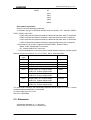
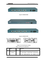
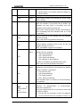
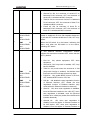
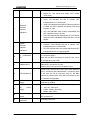
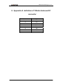
RC953-FE4E1/8E1 User Manual Raisecom Technology Co., Ltd (09/2006) Raisecom Technology Co., Ltd Contents 1. Cautions.............................................................................................................. 1 2. Overview............................................................................................................. 2 2.1. 2.2. 2.3. 3. Main features............................................................................................... 2 Part number specification ............................................................................ 2 Dimension.................................................................................................... 3 Parameters ......................................................................................................... 4 3.1. Basic configuration ...................................................................................... 4 3.2. Ethernet interface parameters ..................................................................... 4 3.2.1. Electrical Ethernet interface.................................................................. 4 3.2.2. Optical Ethernet interface ..................................................................... 4 3.3. E1 interface parameters .............................................................................. 4 3.4. Power supply ............................................................................................... 5 3.5. Ambience..................................................................................................... 5 4. How to use.......................................................................................................... 6 4.1. 5. Equipment explanation ................................................................................ 6 Installation & preparation .................................................................................. 13 5.1. Preparation before Installation ................................................................... 13 5.2. Installation ................................................................................................. 13 5.2.1. Cable preparation ............................................................................... 13 5.2.2. Set the DIP-switch .............................................................................. 13 5.2.3. Connect the fast Ethernet interface .................................................... 14 5.2.4. Connect the E1 cable ......................................................................... 14 5.2.5. Power on ............................................................................................ 14 5.2.6. Service configuration .......................................................................... 14 6. Q & A ................................................................................................................ 15 7. Appendix A: definition of 120ohm balanced E1 connector................................ 16 8. Appendix B: Abbreviations ................................................................................ 17 2 Raisecom Technology Co., Ltd 1. Cautions Please read the following notices carefully before installing and using the device, Raisecom does not respond to any loss that caused by violating safety notice. This series product is integrated device that has precise elements, please avoid violent shakes and impacts, and do not disassemble or maintain the device yourself. If it is required, please do it under the guide of our technical staff following in the steps of anti static. Please contact us if there is any need. There must be grounding protection for the sake of safety; do not disassemble the device yourself, we regard it as you waiver your rights of repair guarantee. 1 Raisecom Technology Co., Ltd 2. Overview RC953-FE4E1/8E1 (RC953-FX4E1/8E1) is Inverse Multiplexer which delivers Ethernet services over existing TDM transportation network. These equipments can be used in point-to-point topology and hub-and-spoke topology with RC953-8FE16E1 located in the central office. RC953-FE4E1 (RC953-FX4E1) allows the transmission of fast Ethernet over 4 bonded E1 circuits (8M) and RC953-FE8E1 (RC953-FX8E1) allows the transmission of fast Ethernet over up to 8 bonded E1 circuits (up to 16M). There is optical option for fast Ethernet port to provide an economical path towards extending the distance of an existing Ethernet network. Additionally its advanced features such as automatic E1 link adjustment provide our carriers a cost-effective, flexible and reliable solution for high-quality Ethernet Service delivery by using TDM network resources. 2.1. Main features z z z z z z z z z z z z z . Provide 4 or 8 E1 interface; Provide 1 Ethernet interface and can be either optical or electrical: Electrical Ethernet interface: auto negotiation, AUTO-MIDX, 10M/100M, full/half duplex, IEEE802.3x flow control on full duplex and back pressure on half duplex. Optical Ethernet interface: 100FX HDLC-over-E1 encapsulation E1 link sequence auto-sensing The maximum jitter of E1 in a transmission channel is +/-16ms Automatically adjust the E1 link capacity of transmission channel if one or more E1 link fails E1 loop back and BERT function Complete E1 line indicators on front panel E1 connector type: balanced (RJ-45) and unbalanced (BNC) Remote manageable 1U chassis and can be installed in 19’’ rack Power consumption <10W (at maximum load) Working temperature: -5℃- 50℃ 2.2. Part number specification Part number: RC953 - A - B - C- D FE8E1 BL M AC FX8E1 Blank S1 DC FE4E1 S2 2 Raisecom Technology Co., Ltd FX4E1 S3 SS13 SS15 SS23 SS25 Blank Part number explanation: RC953: inverse multiplexing equipment A: indicates the type of Ethernet interface and the number of E1 interface: FE8E1, FX8E1, FE4E1 and FX4E1. FE8E1 indicates the Ethernet interface is electrical and there are 8 E1 interfaces. FX8E1 indicates the Ethernet interface is optical and there are 8 E1 interfaces. FE4E1 indicates the Ethernet interface is electrical and there are 4 E1 interfaces. FX4E1 indicates the Ethernet interface is optical and there are 4 E1 interfaces. B: this field is only for 8 E1 equipments (RC953-FE8E1, RC953-FX8E1) Blank: 75ohm unbalanced E1 connector. BL: 120ohm balanced E1 connector. C: this field indicates the connector type of optical Ethernet interface, and the optical Ethernet connector can be M, S1, S2, S3, SS13, SS15, SS23 and SS25. Connector type Wavelength Distance M Multi mode, 1310nm (*) 0-2Km S1 Single mode, 1310nm 0-25Km S2 Single mode, 1310nm 10-60Km S3 Single mode, 1550nm 15-120Km SS13 Single mode, TX: 1310nm Single mode, RX: 1550nm Single mode 0-25Km SS15 Single mode, TX: 1550nm Single mode, RX: 1310nm Single mode 0-25Km SS23 Single mode, TX: 1310nm Single mode, RX: 1550nm Single mode 10-50Km SS25 Single mode, TX: 1550nm Single mode, RX: 1310nm Single mode 10-50Km *For multi mode connector, the transmission distance can be 850nm or 1310nm. 1310nm is default settings and 850nm is customized. D: power supply type: AC or DC 24V DC is customized 2.3. Dimension International standard 19’’ 1U structure: 430mm (W) ×44.45mm× (H) ×266mm (D) 3 Raisecom Technology Co., Ltd 3. Parameters 3.1. Basic configuration z z Main circuit: 1 electrical or optical Ethernet interface, 4 or 8 E1 interfaces. Power supply: 90-264V/AC or -36V- -72V/DC 3.2. Ethernet interface parameters 3.2.1. Electrical Ethernet interface z z z z z Speed: 10/100M auto-negotiation Connector: RJ-45 IEEE802.3 compliant IEEE802.3x flow control AUTO-MDI/MDIX 3.2.2. Optical Ethernet interface z z Speed: 100M Connector: SC 3.3. E1 interface parameters z z z HDLC-over-E1 encapsulation Adopt frame-interleave multiplexing to realize the transportation of Ethernet over multiple E1 E1 link sequence auto-sensing z The maximum jitter of E1 in a transmission channel is +/-16ms z 4M Bytes buffer for each Ethernet port to avoid packet loss z Automatically adjust the E1 link capacity of transmission channel if one or more E1 link fails z For RC953-FE4E1 and RC953-FX4E1, there are both balanced and unbalanced E1 connector (RJ-45 and BNC), you can use DIP-switch to choose the connector type z Bit rate: 2048Kbps±50ppm. z Line coding: HDB3. z 75ohm unbalanced or 120ohm balanced E1 connector. z Electric characteristic: ITU-T G.703 compliant. z Frame structure: ITU-T G.704 compliant z Jitter: ITU-T G.823 compliant. 4 Raisecom Technology Co., Ltd z z z z z z Only support framed E1 (PCM31, FAS+CRC4 by default), CRC auto-negotiation and is configurable There are four status indicators for each E1 circuit: LOS: Loss of Signal (local) PAT: indicator for BERT LER: local E1 general alarm, including AIS(alarm indication signal), LOF( Loss of Frame), CRC(Cyclic Redundancy Check) RAL: remote E1 alarm, including LOS, AIS, LOF, CRC Local and remote E1 loop back E1 BERT (bit error rate tester) function The DIP-switch on the front panel is for the following functions’ configuration Master and slave management Enable and disable loop back Local and remote E1 loop back BERT function Auto negotiation, speed and duplex configuration of Ethernet interface Clock mode configuration Remote manageable by RC953-8FE16E1 3.4. Power supply z z Voltage range: -48VDC, –36V - -72V 220VAC, 90V- 264V Power consumption: <10W 3.5. Ambience z z Temperature: -5℃-50℃ Relative Humidity: ≤90%(35℃) 5 Raisecom Technology Co., Ltd 4. How to use 4.1. Equipment explanation Figure 4-1 RC953-FE8E1 Figure 4-2 RC953-FX8E1 6 Raisecom Technology Co., Ltd Figure 4-3 RC953-FE8E1-BL Figure 4-4 RC953-FX8E1-BL 7 Raisecom Technology Co., Ltd Figure 4-5 RC953-FE4E1 Figure 4-6 RC953-FX4E1 Figure 4-7 AC and DC power supply Table 4-1 RC953 panel explanation Numb er 1 Name LOGO and part number Indicator color Description Both optical Ethernet interface and electrical Ethernet interface devices are indicated by FE, that is to say: z RC953-FE8E1, RC953-FX8E1, RC953-FE8E1-Bl and RC953-FX8E1-BL are labeled as by 8 Raisecom Technology Co., Ltd z 2 SYS Green Flashing indicates the system works normally PWR Green Power supply indicator, ON indicates the power supply works normally LOOP Yellow Loop back indicator. When the remoter E1 loop back test is enable, ON indicates the loop back is successful and OFF indicates unsuccessful loop back test; When local E1 loop back test is enable, ON indicates is test is processing and OFF indicates there is no local E1 loop back. Red Each E1 line has a LOS indicator and ON indicates local loss of signal. * Both LOS and LER ON indicate GID alarm. Yellow Each E1 line has a PAT indicator: when enable BERT function flashing indicates there is error bit and ON indicates there is no error bit. *OFF, when BERT function is not enabled. Red or yellow Each E1 line has a LER indicator which indicates other alarms of E1 line, including: z AIS: Red and flashing; z LOF: yellow and ON; z CRC: yellow and flashing; z OFF indicates no above alarms; * If there is LOS alarm, this indicator will be OFF * Both LOS and LER ON indicate GID alarm. Red or yellow RAL Each E1 line has a RAL indicator. If the remote E1 equipment is also Raisecom, this indicator can indicate alarms of remote E1 equipment: z LOS, Red and ON; z AIS, Red and flashing; z LOF, Yellow and ON; z CRC, Yellow and flashing; *OFF indicates there is no alarm on remote Raisecom E1 equipment. SW1 for RC953-FE4E1 and RC953-FX4E1 This bank of DIP-switch indicates the type of E1 connector for RC953-FE4E1 or RC953-FX4E1: balanced or unbalanced. ON is in the bottom and OFF is in the above, all the bits are OFF by default. z First bit: ON, the connector of first E1 is balanced RJ-45 connector;OFF, the connector of first E1 is 3 LOS PAT LER 4 5 RC953-FE8E1; RC953-FE4E1 and RC953-FX4E1are labeled as RC953-FE4E1; 9 Raisecom Technology Co., Ltd z z z 6 SW2 for RC953-FE4E1 and RC953-FX4E1. SW1 for RC953-FE8E1 and RC953-FX8E1 unbalanced BNC connector; Second bit: ON, the connector of second E1 is balanced RJ-45 connector; OFF, the connector of second E1 is unbalanced BNC connector; Third bit: ON, the connector of third E1 is balanced RJ-45 connector; OFF, the connector of third E1 is unbalanced BNC connector; Fourth bit: ON, he connector of fourth E1 is balanced RJ-45 connector; OFF, the connector of fourth E1 is unbalanced BNC connector Enable or disable the E1 link, ON indicates disable the E1 link and OFF indicates enable the E1 link, OFF is by default. *When the DIP-switch is in the bottom, indicating ON status ; and when the DIP-switch is on the above, indicating OFF status. E1 and Ethernet interface configuration. Bottom indicates ON and above indicates OFF, all the bits are OFF by default: z z z 7 SW3 for RC953-FE4E1 and RC953-FX4E1. SW2 for RC953-FE8E1 and RC953-FX8E1 z z z z First bit: ON, master equipment; OFF, slave equipment. Second bit, ON, loop back is enabled; OFF, loop back is disabled. Third bit: only works when the second bit is ON (loop back function is enabled). ON indicate local loop back and OFF indicates remote loop back. Fourth bit: ON, enable BERT function of E1 line; OFF, disable BERT function of E1 line. Fifth bit: ON, disable the auto negotiation function of Ethernet interface; OFF, enable the auto negotiation function of Ethernet interface (only works when the Ethernet interface is electrical). Sixth bit: ON, when auto negotiation is disabled, force the Ethernet interface to be 10M; OFF, when auto negotiation is disabled, force the Ethernet interface to be 100M (only works when the Ethernet interface electrical). Seventh bit: ON, when auto negotiation is disabled, force the duplex of Ethernet interface to be half duplex; OFF, when auto negotiation is disabled, force the duplex of Ethernet interface to 10 Raisecom Technology Co., Ltd z 8 Electrical Ethernet interface indicators 9 Optical Ethernet interface indicators be full duplex. Eighth bit: ON, slave clock mode; OFF, master clock mode. Green There are 4 indicators for electrical Ethernet interface: z LNKT: ON indicates the link is normal; OFF indicates there is no normal link. z 100M: ON indicates the speed of Ethernet interface is 100M and OFF indicates the speed of Ethernet interface is 10M. z ACT: ON indicates data is being transmitted and OFF indicates there is no data. z FDX: ON indicates the Ethernet link is in full duplex mode and OFF indicates the Ethernet link is in half duplex. Green There are 2 indicators for optical Ethernet interface z LNK/ACT: ON indicates the link is normal; OFF indicates there is no normal link. z SD: ON indicates there are optical signals and OFF indicates there are no optical signals. 8 unbalanced E1 RC953-FE8E1 and RC953-FX8E1 have 8 unbalanced E1 connectors (BNC). There are two BNC connectors for each E1 line, one is TX and the other one is RX. 8 balanced E1 RC953-FE8E1–BL and RC953-FX8E1–BL have 8 balanced E1 connectors (RJ-45). There is one RJ-45 connector for each E1 line. 12 4 E1 equipment RC953-FE4E1 and RC953-FX4E1 have both balanced and E1 connector and unbalanced E1 connector (each E1 link has one RJ-45 connector and TX, RX BNC connectors). Please refer to the SW1 DIP-switch for the E1 connector configuration. 13 AC supply AC power is supplied through a standard IEC 3-prong receptacle by default. 10 11 power 14 DC supply power 15 Power switch supply 16 Grounding connector There are three connectors for DC power supply: : z -48V: left, -48V input z PGND: middle, grounding. z BGND: right, return. ON: powered on. OFF: powered off. Grounding connector. 11 Raisecom Technology Co., Ltd 5. Typical application Point-to-point application Point-to-point application with remote management Hub-and-spoke application with remote management 12 Raisecom Technology Co., Ltd 6. Installation & preparation 6.1. Preparation before Installation Please check if the models and part numbers are in consistence first, and also check if the equipments are damaged. There must be drying process if the equipment is damped. Please follow the following steps when install and use this equipment: z Carefully read this manual z Fix and install the equipment z Connect E1 cable and Ethernet cable z Configure the equipment according to the configuration guide z Use the equipment correctly 6.2. Installation 6.2.1. Cable preparation The following cables need to be prepared: Table 6-1 Cable specification for RC953 connectors Connector Cable specification 10/100Mbps Electrical Ethernet connector Cat. 5 100Base-T UTP, and the maximum (SNMP management length is 100m (prepared by customers) connector) Please prepare the optical fiber for different types Optical fiber for SC of optical fiber connectors (prepared by connector customers) 75ohm unbalanced BNC cable Prepared by customers 120ohm balanced RJ45 cable Prepared by customers Power connector AC power supply: provide one AC power supply cable. DC power supply: provide one DC power supply cable. supply 6.2.2. Set the DIP-switch Please set the DIP-switch according to your requirements, refer to table 4-1for DIP-switch definition. 13 Raisecom Technology Co., Ltd 6.2.3. Connect the fast Ethernet interface For electrical Ethernet interface: connect one end of the Cat. 5 UTP cable with Ethernet router/switch and one end of the cable with the fast electrical Ethernet port of RC953. The LNK indicator will be ON after correct connection. For optical Ethernet interface: connect one end of the fiber with optical router/switch and the other end with the optical Ethernet interface of RC953. 6.2.4. Connect the E1 cable For unbalanced E1 equipment: use 75ohm unbalanced BNC cable. For balanced E1 equipment: use 120ohm balanced RJ-45 cable. 6.2.5. Power on If power supply is DC –48V, first connect middle end to PGND. Turn off Power Supply, connect “-48V” end with the lower electric level cable, “0V” end with higher electric level cable. Make sure no reverse connection, or no short circuited, and then turn on power. When Power Supply is turned on, the PWR indicator should be ON. 6.2.6. Service configuration Please refer to the command notebook and configuration guide of RC953-8FE16E1 for the service configuration. 14 Raisecom Technology Co., Ltd 7. Q & A If there are any problems during installation and using, try the following proposals. If the problems still can not be solved, please contact distributors/agents for help. z PWR, PWR1 and PWR2 are all OFF Please check if power supply cable is connected and then check if the Power Supply Board works normally z SYS indicator is not flashing The equipment is down, please restart the device or tell us. Please remember that the SYS indicator will become flashing a little time later after powered on. z E1 LOS indicator is ON Loss of receiving signal occurs at e1 port. Check whether E1 cable is connected correctly; if there is still LOS alarm please change the E1 cable otherwise there is something wrong with the equipment. z Ethernet LINK indicator OFF Please check if the UTP cable is broken off first and then check if the equipment that connects with RC953-8FE16E1 works normally. Please make sure that the correct Ethernet cable is used. 15 Raisecom Technology Co., Ltd 8. Appendix A: definition of 120ohm balanced E1 connector RJ45 pin number Signal 1 TX+ 2 TX- 3 NC 4 RX+ 5 RX- 6 NC 7 NC 8 NC 16 Raisecom Technology Co., Ltd 9. Appendix B: Abbreviations EoPDH PDH FAS LOS LOF AIS CRC LER RAL PAT SD GID Ethernet over PDH Pseudo-synchronous Digital Hierarchy Frame Alignment Signaling Loss of Signal Loss of Frame Alarm Indication Signal Cyclic Redundancy Check Local Error Alarm: including AIS, LOF and CRC alarms. Remote Alarm: including LOS, AIS, LOF and CRC alarms. Pattern: indicates whether BERT function is started Signal Detect Group Identification: E1 links belong to one transmission channel have the same ID. 17 Raisecom Technology Co., Ltd @2006 Raisecom Technology Co., Ltd. All trademarks are the property of their respective owners. Technical information may be subject to change without prior notification. 18