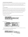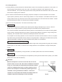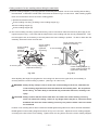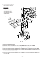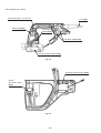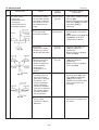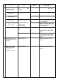
1
MODELS
C 12LDH
C 12FDH
Hitachi
Power Tools
C
COMPOUND MITER SAW
C 12LDH
C 12FDH
LIST Nos. C 12LDH: E943
C 12FDH: E944
TECHNICAL DATA
AND
SERVICE MANUAL
Oct. 2005
SPECIFICATIONS AND PARTS ARE SUBJECT TO CHANGE FOR IMPROVEMENT
REMARK:
Throughout this TECHNICAL DATA AND SERVICE MANUAL, a symbol(s)
is(are) used in the place of company name(s) and model name(s) of our
competitor(s). The symbol(s) utilized here is(are) as follows:
Competitor
Symbol Utilized
Company Name
Model Name
B
BOSCH
4212L
P
DEWALT
DW716
Q
DELTA
36-412
CONTENTS
Page
1. PRODUCT NAME ............................................................................................................................ 1
2. MARKETING OBJECTIVE .............................................................................................................. 1
3. APPLICATIONS ............................................................................................................................... 1
4. SELLING POINTS ........................................................................................................................... 1
4-1. Selling Point Descriptions ................................................................................................................ 2
5. SPECIFICATIONS ........................................................................................................................... 4
6. COMPARISONS WITH SIMILAR PRODUCTS ............................................................................... 6
7. PRECAUTIONS IN SALES PROMOTION ...................................................................................... 7
7-1. Instruction Manual ............................................................................................................................7
7-2. Warning Labels and Caution Labels .................................................................................................7
7-3. Relative Standards ...........................................................................................................................9
7-4. Laser Marker ..................................................................................................................................... 9
7-5. Ambient Illuminance and Visibility of Laser Line .............................................................................10
8. ADJUSTMENT AND OPERATION PRECAUTIONS ...................................................................... 11
8-1. Position Adjustment of Laser Line .................................................................................................. 11
8-2. Before Cutting .................................................................................................................................13
8-3. How to Use the Vise Assembly .......................................................................................................14
8-4. Confirmation for Use of Sub Fence ................................................................................................ 15
8-5. Cutting Operation ............................................................................................................................ 17
8-6. Digital Display Panel (For Model C 12LDH) ...................................................................................22
9. ADJUSTMENT OF COMPONENTS .............................................................................................. 23
9-1. Bevel Angle Fine Adjustment .......................................................................................................... 23
10. PACKING ..................................................................................................................................... 24
11. PRECAUTIONS IN DISASSEMBLY AND REASSEMBLY .......................................................... 25
11-1. Precautions in Disassembly and Reassembly of the Laser Marker .............................................. 25
11-2. Disassembly ..................................................................................................................................25
11-3. Reassembly ..................................................................................................................................35
11-4. Wiring Diagram ............................................................................................................................. 36
11-5. No-load Current ............................................................................................................................. 40
11-6. Reassembly Requiring Adjustment ............................................................................................... 40
Page
11-7. Lubrication ...................................................................................................................................... 41
11-8. Product Precision ........................................................................................................................... 41
11-9. Adjustment of Laser Marker Accuracy ........................................................................................... 42
11-10. Tightening Torque ......................................................................................................................... 45
12. REPAIR GUIDE ............................................................................................................................ 46
13. STANDARD REPAIR TIME (UNIT) SCHEDULES ....................................................................... 51
Assembly Diagram for C 12LDH
Assembly Diagram for C 12FDH
1. PRODUCT NAME
Hitachi Compound Miter Saw, Models C 12LDH and C 12FDH
2. MARKETING OBJECTIVE
Following the 12" compound miter saw Model C 12LCH equipped with the laser marker, we introduce the new two
12" compound miter saws Models C 12LDH and C 12FDH. The Model C 12LDH is equipped with the class-first
digital display panel that indicates miter/bevel angles. In addition, the Models C 12LDH and C 12FDH can
perform bevel cutting at 45˚ in either left or right direction efficiently without moving the workpiece. With the new
Models C 12LDH and C 12FDH, we aim to expand our market share.
3. APPLICATIONS
Cutting various types of wood workpieces
Cutting workpieces of plywood, decoration panels, soft fiberboard and hard board
Cutting aluminum sashes
4. SELLING POINTS
(7)
Aggressive tool design
(5)
(3)
Bevel cutting in either
left or right direction
Left bevel cutting:
H50 x W203 (mm)
H55 x W190 (mm)
Right bevel cutting:
H31 x W203 (mm)
H38 x W190 (mm)
(8)
(10)
Soft vibration
reducing grip
Dust guide to prevent
chips from scattering
Powerful 15 amps motor
(For U.S.A. and Canada)
(2)
Laser guide system
For easier alignment
with the ink line
(4)
Bevel angle fine adjustment
(6)
130-mm high fence
(Turning sub fence)
(1) Digital display panel that
indicates miter/bevel angles
(Model C 12LDH)
--- 1 ---
(9)
Thumb actuated positive
stops for quick and easy
miter adjustment
4-1. Selling Point Descriptions
(1) Digital display panel that indicates miter/bevel angles (Model C 12LDH)
Use the digital display panel when cutting a workpiece at an
optional angle. The class-first digital display panel indicates a
Laser line
miter/bevel cutting angle with a numeric value. There is no
reading error caused by visual check between the indicator and
the scale. The digital display indicates a miter angle or a bevel
angle in increments of 0.5˚. The digital display is equipped with
the convenient back light ON/OFF switch that makes the display
Ink line
easily readable even in a dimly lit place.
Fig. 1
(2) Laser guide system
Use the laser marker for aligning with the ink line on the workpiece.
1
Cutting position can be properly adjusted by aligning the positioning ink line with the laser line. There is no
need to make a long ink line on the workpiece.
2
There is no need to lower the motor head to align with the ink line because the laser marker makes a laser
line on the workpiece. In addition, cutting position can be easily adjusted because the operator can hold the
workpiece with both hands to move.
3
Cutting position can be easily adjusted because the laser line can be aligned with an optionally angled ink
line.
4
Even the workpieces such as crown moldings and base boards that have decorative surfaces and are
difficult to be made an ink line can be cut just by aligning the laser line with the ink line on the fence side.
The laser line is adjusted to the width of the saw blade at the time of factory shipment. Depending upon the
user's cutting choice, the laser line can be aligned with the left side of the cutting width (saw blade) or the
ink line on the right side. Adjust the position of the laser line according to "8-1. Position Adjustment of Laser
Line" on page 11.
(3) Bevel cutting in either left or right direction
1
Maximum cutting dimensions
Table 1
Bevel left 45˚
Maker •
Model
Maximum
cutting
dimensions
Hitachi
C 12LDH
Bevel left 45˚
Height x Width
50 x 203
[55 x 190]
Bevel right 45˚
Height x Width
31 x 203
[38 x 190]
Bevel right 45˚
Width
Height
Workpiece
The Models C 12LDH and C 12 FDH
can perform bevel cutting for the
workpieces shown in Table 1 by
inclining the saw blade section in
either left or right direction.
Fig. 2
--- 2 ---
(4) Bevel angle fine adjustment
The Models C 12LDH and C 12FDH are easily and finely adjustable to an optional bevel angle. Pulling the
plate allows the bevel angle to be adjusted by about 48˚ to the left or about 48˚ to the right with one-touch
simple operation.
(5) Soft, vibration reducing grip
The handle grip is comfortable and slip-resistant thanks to the integrally molded rubber. In addition, it reduces
vibration transmitted to the operator's hand. The Models C 12LDH and C 12FDH are easier to operate.
(6) 130-mm high fence (Turning sub fence)
The Models C 12LDH and C 12FDH realize stable cutting thanks to the widely supportable high fence.
(7) Aggressive tool design
The tool color is gunmetallic silver to give a sturdier image. The circular saw portion is of a powerful, original
and aggressive design.
(8) Powerful 15 amps motor
The Models C 12LDH and C 12FDH are equipped with a 15-ampere motor. The Models C 12LDH and
C 12FDH can cut workpieces as quickly as the Model C 12LCH.
(9) Thumb actuated positive stops for quick and easy miter adjustment
The positive stops are provided to adjust the turn table position for miter cutting securely. These stops can be
actuated (fixed or released) with thumb quickly and easily holding the side handle.
(10) Dust guide to prevent chips from scattering
A dust guide is provided to prevent wood chips from adhering to the saw blade and scattering when cutting the
edge of the workpiece.
--- 3 ---
5. SPECIFICATIONS
Maximum
cutting
dimensions
Height x
Width
0˚ (Right angle)
70 mm (2-3/4") x 203 mm (8")
89 mm (3-1/2") x 190 mm (7-1/2")
Miter right/left 45˚
70 mm (2-3/4") x 140 mm (5-1/2")
Miter right/left 52˚
70 mm (2-3/4") x 120 mm (4-3/4")
Bevel left 45˚
50 mm (1-31/32") x 203 mm (8")
Bevel right 45˚
31 mm (1-7/32") x 203 mm (8")
Miter right/left 45˚
+
Bevel left 45˚
Miter right/left 45˚
+
Bevel right 45˚
Miter cutting ranges
Right and left 0˚ --- 52˚
Bevel cutting ranges
Right and left 0˚ --- 48˚
Compound (miter + bevel)
cutting ranges
Miter: Right and left 0˚ --- 45˚, Bevel: Right and left 0˚ --- 45˚
Angle stopper positions
Right and left 0˚, 15˚, 22.5˚, 31.6˚, 45˚
Saw blade outer diameter
305 mm (12") external dia.
Digital display
(For Models C 12LDH)
Precision
50 mm (1-31/32") x 140 mm (5-1/2")
31 mm (1-7/32") x 140 mm (5-1/2")
0.5˚ (It is not the actual precision when cutting a wood workpiece.)
Maximum output < 1 mW (CLASS II )
Laser marker
Wave length
400 nm --- 700 nm
Laser medium
Laser diode
Power source type and voltage
AC single phase 60 Hz, 120 V
Type of motor
AC single phase commutator series motor
Full-load current
15 A
No-load rotation speed
4,000 min-1
Max. output
1,950 W
Main unit dimensions
Width x Depth x Height
625 mm x 780 mm x 685 mm (24-5/8" x 30-23/32" x 27")
Weight
C 12LDH
21.5 kg (47.4 Ibs.), gross weight 28 kg (61.7 Ibs.)
C 12FDH
21.0 kg (46.3 Ibs.), gross weight 27.5 kg (60.6 Ibs.)
Coating
Packaging
Cord
Standard accessories
Gunmetallic silver
Corrugated cardboard box
Type: 2-conductor cabtire cable
Length: 2.0 m (6.7 ft)
305 mm (12") TCT saw blade (32 teeth, Code No. 323522)
for wood cutting
Dust bag
Vise ass'y
17 mm box wrench
4 mm hex. bar wrench
• • • • • • • • • • • • • • •
--- 4 ---
Optional accessories
305 mm (12") TCT saw blade (60 teeth, Code No. 305546)
Extension holder and stopper (Code No. 323523)
Crown molding vise ass'y (including crown molding stopper (L))
(Code No. 323545)
Crown molding stopper (L) (Code No. 323546)
Crown molding stopper (R) (Code No. 323547)
--- 5 ---
6. COMPARISONS WITH SIMILAR PRODUCTS
Maker/Model
Item
P
Q
B
70 mm x 203 mm
(2-3/4" x 8")
89 mm x 190 mm
(3-1/2" x 7-1/2")
70 mm x 140 mm
(2-3/4" x 5-1/2")
74 mm x 201 mm
(2-29/32" x 7-29/32")
89 mm x 188 mm
(3-1/2" x 7-13/32")
63.5 mm x 235 mm
(2-1/2" x 9-1/4")
89 mm x 165 mm
(3-1/2" x 6-1/2")
63.5 mm x 200 mm
(2-1/2" x 7-7/8")
100 mm x 155 mm
(3-15/16" x 6-3/16")
74 mm x 142 mm
(2-29/32" x 5-19/32")
63.5 mm x 165 mm
(2-1/2" x 6-1/2")
63.5 mm x 140 mm
(2-1/2" x 5-1/2")
Bevel left 45˚
50 mm x 203 mm
(1-31/32" x 8")
48 mm x 201 mm
(1-7/8" x 7-29/32")
43 mm x 235 mm
(1-11/16" x 9-1/4")
55 mm x 200 mm
(2-3/16" x 7-7/8")
Bevel right 45˚
31 mm x 203 mm
(1-7/32" x 8")
30 mm x 201 mm
(1-3/16" x 7-29/32")
24 mm x 235 mm
(15/16" x 9-1/4")
27 mm x 155 mm
(1-1/16" x 6-3/16")
50 mm x 140 mm
(1-31/32" x 5-1/2")
48 mm x 142 mm
(1-7/8" x 5-19/32")
43 mm x 165 mm
(1-11/16" x 6-1/2")
40 mm x 140 mm
(1-9/16" x 5-1/2")
31 mm x 140 mm
(1-7/32" x 5-1/2")
30 mm x 142 mm
(1-3/16" x 5-19/32")
--( --- )
--( --- )
0˚ (Right angle)
Max.
cutting
dimensions
Height
x Width
HITACHI
C 12LDH/C 12FDH
Miter right/left 45˚
Miter right/left 45˚
+
Bevel left 45˚
Miter right/left 45˚
+
Bevel right 45˚
Miter cutting ranges
Right and left 0˚--- 52˚
Right and left 0˚--- 50˚
Right and left 0˚--- 48˚
Right and left 0˚--- 52˚
Bevel cutting ranges
Right and left 0˚--- 48˚
Right and left 0˚--- 48˚
Right and left 0˚--- 48˚
Right and left 0˚--- 47˚
Compound (miter + bevel)
cutting ranges
Miter: Right and left
Miter: Right and left
Miter: Right and left
0˚ --- 45˚
0˚ --- 48˚
0˚ --- 45˚
Bevel: Right and left 0˚ --- 45˚ Bevel: Right and left 0˚ --- 45˚ Bevel: Right and left 0˚ --- 45˚
Angle stopper position
Right and left 0˚, 15˚,
22.5˚, 31.6˚, 45˚
Right and left 0˚, 10˚,
15˚, 22.5˚, 31.6˚, 45˚
Right and left 0˚, 15˚,
22.5˚, 31.6˚, 45˚
Right and left 0˚, 15˚,
22.5˚, 31.6˚, 45˚, 60˚
305 (12") (32 teeth)
305 (12") (60 teeth)
305 (12") (60 teeth)
305 (12") (40 teeth)
None
None
None
Saw blade outer diameter (mm)
Motor
Digital display
Full-load current (A)
No-load revolution (min-1)
Power input (W)
Max. output (W)
Laser marker
Laser output
Insulation structure
Dust guide
Dust bag size (mm)
Main unit dimensions
Width x Depth x Height
Product weight (kg)
Standard accessories
Optional accessories
Provided
(Models C 12LDH)
Miter: Right and left
0˚ --- 47˚
Bevel: Right and left 0˚--- 52˚
15
15
15
15
4,000
4,000
4,200
3,800
Provided
Not provided
Double insulation
Double insulation
Double insulation
Double insulation
Provided (fixed)
None
None
220 x 180
(8-21/32" x 7-3/32")
None
300 x 200
(11-13/16" x 7-7/8")
630 x 670 x 735
645 x 760 x 730
1,520
1,950
Provided
Provided (Laser tracking)
< 1 mW
250 x 160
(9-27/32" x 6-5/16")
625 x 780 x 685
625 x 690 x 655
(24-5/8" x 30-23/32" x 27") (24-5/8" x 27-5/32" x 25-25/32") (24-13/16" x 26-3/8" x 28-15/16") (25-13/32" x 29-15/16" x 28-3/4")
C 12LDH
C 12FDH
21.5 (47.4 lbs.) 21 (46.3 lbs.)
20.5 (45.1 lbs.)
24.0 (52.8 lbs.)
26.0 (57.2 lbs.)
• 305 mm (12") TCT saw
blade (32 teeth) for
wood cutting
• Dust bag
• Vise ass'y
• 17 mm box wrench
• 4 mm hex. bar wrench
• 305 mm (12") saw blade • 305 mm (12") saw blade • 305 mm (12") saw
• 305 mm (12") TCT saw
blade (60 teeth) for
normal cutting
• Extension holder and
stopper
• Crown molding vise ass'y
(including crown molding
stopper (L))
• Crown molding stopper (L)
• Crown molding stopper (R)
• Extension kit
(60 teeth)
• Dust bag
• Blade wrench
• Length stop
• Crown stops
• Material clamp
--- 6 ---
(60 teeth)
• Dust bag
• Dust spout
• Blade shroud
• 1/2 Arbor wrench
• M4 pan head screw
• Open end 7/16" wrench
blade (40 teeth)
• Vise Ass'y
• Crown molding stopper
ass'y
• Dust bag
• Multi purpose tool
• 3 mm hex. bar wrench
• 10 mm/17 mm wrench
• Combination square
7. PRECAUTIONS IN SALES PROMOTION
In the interest of promoting the safest and most efficient use of the Models C 12LDH and C 12FDH Compound
Miter Saws by all of our customers, it is very important that at the time of sale the salesperson carefully ensures
that the buyer seriously recognizes the importance of the contents of the Instruction Manual, and fully
understands the meaning of the precautions listed on the Warning Labels and Caution Labels attached to each
machine.
7-1. Instruction Manual
Although every effort is made in each step of design, manufacture and inspection to provide protection against
safety hazards, the dangers inherent in the use of any compound miter saw cannot be completely eliminated.
Accordingly, general precautions and suggestions for the use of electric power tools, and specific precautions and
suggestions for the use of the compound miter saw are listed in the Instruction Manual to enhance the safe,
efficient use of the tool by the customer. Salespersons must be thoroughly familiar with the contents of the
Instruction Manual to be able to offer appropriate guidance to the customer during sales promotion.
7-2. Warning Labels and Caution Labels
(1) Precautions on the name plate
Each Model C 12LDH/C 12FDH is furnished with a Name Plate that lists the following precautions.
Fig. 3
(2) Warning label (A)
Fig. 4
Warning label (A) specified by the UL is affixed on the right side of the base. Please instruct users to strictly
observe the contents 1 to 9 in warning label (A) shown above.
(3) Caution label (B) (at the side of the gear case)
Fig. 5
--- 7 ---
(4) Caution label (A) (at the front of the hinge) and caution label (C) (at the front of the base)
Do not stare into laser beam. If your eye is exposed directly to the laser beam, it can be hurt. Caution label
(A) and caution label (C) are adhered to each machine to comply with the standards for the safe use of laser
equipment.
Caution label (A) (at the front of the hinge)
Fig. 6
Caution label (C) (at the front of the base)
Fig. 7
(5) Warning label (M) (at the front of sub fence (A) (standard accessory))
Fig. 8
(6) Caution label (L) (at the front of sub fence (B) (standard accessory))
Fig. 9
--- 8 ---
(7) Warning label (O) (at the front of sub fence (C) (standard accessory))
Fig. 10
7-3. Relative Standards
Standards, regulations and guidelines for the safe use of laser equipment.
[The U. S. A.]
There is a standard "Complies with 21 Code of Federal Regulation (21 CFR), Chapter 1, Subchapter J, Part 1010
and 1040" established by the Center for Devices and Radiological Health (CDRH) of the Food and Drug
Administration (FDA). Standards, regulations and guidelines of the other countries are under investigation.
7-4. Laser Marker
The Models C 12LDH and C 12FDH are equipped with the laser marker that complies with the U. S. A. standard,
FDA Complies with 21 CFR, Food and Drugs, Part 1040 "Performance Standard for Light-emitting Products",
Class II. The Class II laser is defined as follows:
The laser power is low and it is safe by the protective measures such as blinking. However, it is dangerous if
the operator's eyes are exposed directly to the laser for a protracted period.
The operator can use the laser equipment without particular training and instruction.
The amount of light exposure (output) is 1 mW or less at the position where the operator can be exposed to
the laser radiation during operation.
Table 2
Wave length
(nm)
> 400
< 710
Class II accessible emission limit
Emission duration (s)
> 2.5 x 10⁻¹
(Threshold value)
(Unit)
(Amount)
1.0 x 10⁻³
W
Radiant power
The saw blade unit prevents access of the operator's eye to the laser emitting aperture less than 65 mm.
In addition, the amount of light exposure (output) is 1 mW or less (about 0.4 mW) at this position. Thus the
Models C 12LDH and C 12FDH satisfy the Class II requirements adequately. There is no ill effect on the
operator's body if looking at the laser line on the workpiece during operation.
CAUTION: (1) Be sure to disconnect the power cord plug from the receptacle before removing the laser
marker for repair. If it is unavoidable to check the operation of the removed laser marker
with the power turned on, face the laser emitting aperture to the ground to show the laser
line on the ground.
(2) Laser radiation when open. DO NOT STARE INTO BEAM OR VIEW DIRECTLY WITH
OPTICAL INSTRUMENTS.
The lifespan of the laser marker in the Models C 12LDH and C 12FDH are about 2,160 hours. (About three
years: 4 hours of use/day x 180 days/year)
--- 9 ---
7-5. Ambient Illuminance and Visibility of Laser Line
The visibility of the laser line on the workpiece changes depending on the brightness of the working environment.
Instruct the customer to consider the brightness of the working environment when using the laser marker referring
to the following table.
Table 3 Ambient illuminance and visibility of laser line
Illuminance (lux)
Outdoor
Ambient
conditions
(reference)
3000 or more 3000 or more
3000 - 2500
Shaded area
in cloudy
weather
Under direct
Shaded area Cloudy
sunlight of fine in fine weather
weather
weather
Near the
Indoor under
window under
fine weather
fine weather
Indoor
Laser line
Invisible
Visible
800 - 600
300 - 200
Just before the
sunset in
cloudy
weather
Near the
window under Indoor under
cloudy
cloudy
weather
weather
Visible
Visible
150 - 80
Visible
Near the window
under cloudy
weather, just
before the
sunset
Glaring
30 or less
Ink line is
invisible.
Glaring
(The working environment where the illuminance is 200 luxes or less is dark and difficult to operate the Models
C 12LDH and C 12FDH.)
The laser line is invisible under direct sunlight of fine weather. Prepare a shaded area or relocate to a shaded
area to operate the Models C 12LDH and C 12FDH .
--- 10 ---
Digital display
switch
(Model C 12LDH
only)
8. ADJUSTMENT AND OPERATION PRECAUTIONS
8-1. Position Adjustment of Laser Line
The Models C 12LDH and C 12 FDH are equipped with the laser
Laser marker
switch (Models
C 12LDH and
C 12FDH)
marker for easy alignment with the ink line on the workpiece.
Turn on the digital display switch first then turn on the laser
marker switch. In the case of the Model C 12LDH, the laser
marker does not light if the digital display switch is turned off.
Fig. 11
The laser line is adjusted to the width of the saw blade at the time
of factory shipment. Depending upon the cutting choice, align the
laser line with the left side of the cutting width (saw blade) or the
Saw blade
Workpiece
right side according to the following procedure. First, make a
right-angle ink line on the workpiece that is about 38 mm (1-1/2")
in height and 89 mm (3-1/2") in width. To cut the right side of the
Ink line
ink line with the saw blade as shown in Fig. 14, align the left side
Cutting width
of the saw blade with the ink line on the workpiece and make a
Fig. 12
groove of about 5 mm deep on the workpiece to the middle. Hold
the grooved workpiece by the vise as it is and do not move it.
Gear case
Light up the laser marker. Then insert a 4 mm hex. bar wrench in
the 12 diameter hole on the side of the gear case, turn the hex.
4 mm hex. bar wrench
Laser line
Turn
socket set screw to move the laser line. (If you turn the hex.
socket screw clockwise, the laser line will shift to the right and if
you turn it counterclockwise, the laser line will shift to the left.)
Move
(Fig. 13)
Groove
Thus the cutting position matches the laser line position. Align the
Fig. 13
ink line on the workpiece with the laser line. When aligning the
ink line, slide the workpiece little by little and secure it by vise at a
Laser line
position where the laser line overlaps with the ink line (Fig. 14).
Work on the grooving again and check the position of the laser
line. When the ink line and the laser line are overlapped, the
strength and weakness of light will change, resulting in a stable
cutting operation because you can easily discern the conformity of
lines. This ensures the minimum cutting errors.
Ink line
Fig. 14
WARNING:
Make sure before plugging the power plug into the receptacle that the main body and the laser
marker are turned off.
Exercise utmost caution in handling a switch trigger for the position adjustment of the laser line, as
the power plug is plugged into the receptacle during operation. If the switch trigger is pulled
inadvertently, the saw blade can rotate and result in unexpected accidents.
Do not remove the laser marker to be used for other purposes.
--- 11 ---
CAUTION:
Laser radiation - Do not stare into beam.
Laser radiation on work table. Do not stare into beam. If your eye is exposed directly to the laser
beam, it can be hurt.
Do not dismantle it.
Do not give strong impact to the laser marker (main body of tool); otherwise, the position of a laser
line can go out of order, resulting in the damage of the laser marker as well as a shortened service
life.
Keep the laser marker lit only during a cutting operation. Prolonged lighting of the laser marker can
result in a shortened service life.
Use of controls adjustments or performance of procedures other than those specified herein may
result in hazardous radiation exposure.
NOTE:
Perform cutting by overlapping the ink line with the laser line. When the ink line and the laser line
are overlapped, the strength and weakness of light will change, resulting in a stable cutting
operation because you can easily discern the conformity of lines. This ensures the minimum
cutting errors.
In outdoor or near-the-window operations, it may become difficult to observe the laser line due to
the sunlight. Under such circumstances, move to a place that is not directly under the sunlight and
engage in the operation.
Do not tug on the cord behind the motor head or hook your finger, wood and the like around it;
otherwise, the cord may come off and the laser marker may not be lit up.
The laser marker will not light up if the digital display switch is turned off. (Only Model C 12LDH)
Instruct the above precautions on the laser marker to the customers.
--- 12 ---
8-2. Before Cutting
(1) Oblique angle
Before the power tool is shipped from the factory, it is adjusted for 0˚, right angle, left 45˚ bevel cutting angle
and right 45˚ bevel cutting angle with 8 mm bolt (A), 8 mm bolt (B) and 8 mm bolt (C). When changing the
adjustment, change the height of 8 mm bolt (A), 8 mm bolt (B) or 8 mm bolt (C) by turning them.
When changing the bevel angle to the right 45˚, pull the set pin on the direction shown in Fig. 8-b and incline
the motor head to the right.
When adjusting the motor head to 0˚, always return the set pin to its initial position as shown in Fig. 15-a.
NOTE: Do not adjust the 8 mm bolt with bevel plates (Fig. 15-a) pulled.
8 mm bolt (A)
(stopper for 0˚)
Set pin
Indicator
(for right bevel scale)
Return
Bevel plate
Pull
Set pin
Indicator
(for left
bevel scale)
8 mm bolt (B)
(stopper for left 45˚ bevel angle)
8 mm bolt (C)
(stopper for right 45˚ bevel angle)
Fig. 15-a
Fig. 15-b
(2) Securing the workpiece
WARNING: Always clamp or vise to secure the workpiece to the fence; otherwise the workpiece
might be thrust from the table and cause bodily harm.
(3) Installing the holders (Optional accessory)
The holders help keep longer workpieces stable and in place during the cutting operation.
(1) As indicated in Fig. 16, use a steel square for aligning the upper edge of the holders with the base
surface. Loosen the 6 mm wing nut. Turn a height adjustment bolt 6 mm, and adjust the height of the
holder.
(2) After adjustment, firmly tighten the wing nut and fasten the holder with the 6 mm wing bolt (optional
accessory). If the length of the height adjustment bolt 6 mm is insufficient, spread a thin plate beneath.
Make sure the end of the height adjustment bolt 6 mm does not protrude from the holder.
6 mm wing bolt
(optional accessory)
Steel square
Holder
(optional
accessory)
Base
surface
6 mm wing nut
(optional
Height adjustment bolt 6 mm
accessory)
(optional accessory)
Fig. 16
--- 13 ---
(4) Stopper for precision cutting (Stopper and holder are optional accessory)
The stopper facilitates continuous precision cutting in lengths of 11" to 17-3/4" (280 mm to 450 mm).
To install the stopper, attach it to the holder with the 6 mm wing bolt as shown in Fig. 17.
Stopper
(optional accessory)
Workpiece
Holder
(optional accessory)
6 mm wing nut (optional accessory)
Height adjustment bolt 6 mm (optional accessory)
6 mm wing nut
(optional accessory)
Fig. 17
8-3. How to Use the Vise Assembly
Screw holder
6 mm wing bolt (B)
(1) The vise assembly can be mounted on either the left
Knob
fence (fence (B)) or the right fence (fence (A)) by
Vise plate
loosening 6 mm wing bolt (A).
(2) The screw holder can be raised or lowered according to
Fence
the height of the workpiece by loosening 6 mm wing bolt Vise shaft
(B). After the adjustment, firmly tighten 6 mm wing bolt
(B) and fix the screw holder.
(3) Turn the upper knob and securely fix the workpiece in
6 mm wing bolt (A)
position (Fig. 18).
Workpiece
Fig. 18
WARNING: Always firmly clamp or vise to secure the workpiece to the fence; otherwise the workpiece
might be thrust from the table and cause bodily harm.
CAUTION: Always confirm that the motor head does not contact the vise assembly when it is lowered
for cutting. If there is any danger that it may do so, loosen 6 mm wing bolt (B) and move
the vise assembly to a position where it will not contact the saw blade.
--- 14 ---
8-4. Confirmation for Use of Sub Fence
(1) Confirmation for use of sub fence (A)
WARNING: In the case of right bevel cutting, turn sub fence (A) clockwise. Unless it is turned
clockwise, the main body or saw blade may contact sub fence (A), resulting in an injury.
Left bevel angle cutting
Right bevel
Direct angle cutting
Turn angle cutting
This power tool is equipped with sub fence (A).
In the case of direct angle cutting and left bevel angle
cutting, use sub fence (A). Then you can realize
stable cutting of the material with a wide back face.
In the case of right bevel cutting, raise sub fence (A)
up as illustrated in Fig. 19 and then turn it clockwise.
Fence (A)
Sub fence (A)
Fig. 19
(2) Confirmation for use of sub fence (B)
WARNING: In the case of left bevel cutting, turn sub fence (B) counterclockwise. Unless it is turned
counterclockwise, the main body or saw blade may contact sub fence (B), resulting in an
injury.
This power tool is equipped with sub fence (B). In the
Left bevel angle
cutting
Turn
Right bevel angle cutting
Direct angle cutting
case of direct angle cutting and right bevel angle
cutting, use sub fence (B). Then you can realize stable
cutting of the material with a wide back face.
In the case of left bevel cutting, raise sub fence (B) up
as illustrated in Fig. 20 and turn it counterclockwise.
Sub fence (B)
Fence (B)
Fig. 20
(3) Confirmation for use of sub fence (C)
WARNING: In the case of left bevel angle cutting, remove sub fence (C). If sub fence (C) is not
removed, sub fence (C) will contact the main unit or the saw blade and result in injury.
This power tool is equipped with sub fence (C). In the
Sub fence (C)
case of direct angle cutting and right bevel angle
cutting, use sub fence (C). (Fig. 21)
Then you can realize stable cutting of the material with
a wide back face.
Fence (B)
Fig. 21
--- 15 ---
In the case of left bevel angle cutting, remove sub fence (C)
Sub fence (C)
by sliding to the side and removing from the top as shown in
Fence (B)
Fig. 21. Loosen knob (B) then remove sub fence (C) (Fig. 22).
WARNING: To attach sub fence (C), insert then securely
tighten knob (B). If knob (B) is loose, sub
fence (C) may move during cutting and result in
Knob (B)
injury.
Fig. 22
--- 16 ---
8-5. Cutting Operation
(1) Cutting efficiency will be reduced if a dull saw blade is used, if an excessively long extension cord is used, or if
the wire gauge of the extension cord is too small. (For details on extension cords, please refer to the
Instruction Manual.) This is particularly important when cutting materials with dimensions which are at or near
the maximum capacity for the machine.
(2) The customer should be advised to thoroughly inspect the workpiece to ensure that there are no metallic
objects (nails in particular), sand, or other foreign matter in or on the workpiece. Saw blade contact with such
foreign matter will not only shorten the service life of the saw blade, but could cause serious accident. Should
the saw blade tips be broken off, the tips may fly toward the operator.
(3) Direct current cannot be used. The switch can be faulty if used.
(4) Press cutting
The Models C 12LDH and C 12FDH can be used for press cutting of workpieces up to 70 mm x 203 mm
(2-3/4" x 8") in a single operation by simply pushing the saw blade section (head) downward.
The customer should be cautioned that excessive pressure on the handle will not increase the cutting speed.
On the contrary, excessive pressure may result in reduced cutting efficiency (irregular or rough cutting of the
workpiece), and could also cause overload and subsequent burnout of the motor.
On completion of the cutting operation, turn the switch OFF and wait for the saw blade to come to a complete
stop before raising the saw blade section (head) to its original position. Raising the saw blade section (head)
while the saw blade is rotating may cause unwanted cutting marks on the workpiece.
Techniques to avoid unwanted cutting marks
Uneven and unwanted cutting marks can be avoided throughout the cutting operation by gently and smoothly
pressing down on the handle, so that the entire cutting operation is accomplished in a single uninterrupted
motion.
(5) Miter cutting
Miter cutting is accomplished by turning the table. (For details, please refer to the Instruction Manual.)
(6) Bevel cutting
Bevel cutting of 0 --- 45˚ to the left/right is accomplished by inclining the saw blade section (head). (For details,
please refer to the Instruction Manual.)
CAUTION:
When the workpiece is secured on the left side, the cut-off
Fixed-side workpiece
Cut-off-side
workpiece
portion comes to rest on the side of the saw blade as illustrated
in Fig. 23. If the handle is raised before the saw blade rotation
comes to a complete stop, there is a chance that the cut-off
portion of the workpiece could become jammed against the
saw blade, causing a hazardous condition. Instruct the
Saw blade
customer to ensure without fail that the saw blade comes to a
complete stop before attempting to raise the handle.
--- 17 ---
Fig. 23
(7) Compound (miter + bevel) cutting
Compound cutting can be accomplished by combining the miter cutting and bevel cutting operations described
in paragraphs (5) and (6) above. (For details, please refer to the Instruction Manual.) When the saw blade
section (head) is inclined 45˚ to the right and left, the table can be turned up to 45˚ to the right and left.
(8) Crown molding cutting
This machine can cut two types of crown molding workpieces by combining the miter and bevel cutting
operations (for USA).
Figure 24 shows two common crown molding types having angles of (θ) 38˚ and 45˚. For the typical crown
molding fittings, see Fig. 25.
A Upper surface ceiling
θ˚
Ceiling
Wall
B Lower surface
1
Wall
3
2
Inside corner
Fig. 24
4
Outside corner
Fig. 25
The table below shows the miter angle and the bevel angle settings that are ideal for the two crown molding
types.
NOTE: For convenience, positive stops are provided for both the miter setting (left and right 31.6˚) and
the bevel setting positions.
For miter cut setting
If the turn table has been set to either of the angles described, move the turn table adjusting the side
handle a little to the right and left to stabilize the position and to properly align the miter scale and the tip of
the indicator before the operation starts.
For bevel cut setting
Move handle on miter section to the right and left and check that the position is stable and the angle scale
and the tip of the indicator are properly aligned. Then tighten the clamp lever.
Table 4
Type of
crown molding
To process crown molding at
positions 1 and 4 in Fig. 24
To process crown molding at
positions 2 and 3 in Fig. 24
Miter angle
setting
Miter angle
setting
Bevel angle
setting
Bevel angle
setting
45˚ type
Right 35.3˚
( mark)
Left 30˚
( mark)
Left 35.3˚
( mark)
Left 30˚
( mark)
38˚ type
Right 31.6˚
( mark)
Left 33.9˚
( mark)
Left 31.6˚
( mark)
Left 33.9˚
( mark)
--- 18 ---
(1) Setting to cut crown molding at positions 1 and 4 in Fig. 25 (See Fig. 26; tilt the head to the left.):
1 Turn the turn table to the right and set the miter angle as follows:
For 45˚ type crown moldings: 35.3˚ ( mark)
For 38˚ type crown moldings: 31.6˚ ( mark)
2 Turn the head to the left and set the bevel angle as follows:
For 45˚ type crown moldings: 30˚ ( mark)
For 38˚ type crown moldings: 33.9˚ ( mark)
3 Position the crown molding so that the lower surface ( A in Fig. 24) contacts the fence as indicated in
Fig. 28.
(2) Setting to cut crown moldings at positions 2 and 3 in Fig. 25 (See Fig. 27; tilt the head to the left.):
1 Turn the turn table to the left and set the miter angle as follows:
For 45˚ type crown moldings: 35.3˚ ( mark)
For 38˚ type crown moldings: 31.6˚ ( mark)
2 Tilt the head to the left and set the bevel angle as follows:
For 45˚ type crown moldings: 30˚ ( mark)
For 38˚ type crown moldings: 33.9˚ ( mark)
3 Position the crown molding so that the lower surface ( B in Fig. 24) contacts the fence as indicated in
Fig. 29.
CAUTION: In the case of left bevel angle cutting, remove sub fence (C) before operation.
(Figs. 26 and 27)
Sub fence (C)
Head
Sub fence (C)
Head
Bevel angle scale
Bevel angle scale
3
4
Fence (A)
2
1
Miter angle scale
Base
Turn table
Fence (B)
Fig. 26
Base
Turn table
Miter angle scale
Fig. 27
Fence
Fence
A
B
A
B
Table on base
Table on base
Fig. 29
Fig. 28
--- 19 ---
(3) Setting to cut crown moldings at positions 1 and 4 in Fig. 25 (See Fig. 30; tilt the head to the right.):
1 Turn the turn table to the right and set the miter angle as follows:
For 45˚ type crown moldings: 35.3˚ ( mark)
For 38˚ type crown moldings: 31.6˚ ( mark)
2 Tilt the head to the right and set the bevel angle as follows:
For 45˚ type crown moldings: 30˚ ( mark)
For 38˚ type crown moldings: 33.9˚ ( mark)
3 Position the crown molding so that the lower surface ( B in Fig. 24) contacts the fence as indicated in
Fig. 32.
(4) Setting to cut crown moldings at positions 2 and 3 in Fig. 25 (See Fig. 31; tilt the head to the right.):
1 Turn the turn table to the left and set the miter angle as follows:
For 45˚ type crown moldings: 35.3˚ ( mark)
For 38˚ type crown moldings: 31.6˚ ( mark)
2 Tilt the head to the right and set the bevel angle as follows:
For 45˚ type crown moldings: 30˚ ( mark)
For 38˚ type crown moldings: 33.9˚ ( mark)
3 Position the crown molding so that the lower surface ( A in Fig. 24) contacts the fence as indicated in
Fig. 33.
Head
Head
Bevel angle scale
4
Bevel angle scale
Fence (A)
1
Fence (B)
3
2
Miter angle scale
Base
Turn table
Base
Fig. 30
Miter angle scale
Turn table
Fig. 31
Fence
Fence
B
B
A
Table on base
A
Table on base
Fig. 33
Fig. 32
--- 20 ---
Cutting method of crown molding without tilting the saw blade
(1) Crown molding stoppers (L) and (R) (optional accessories) allow easier cuts of crown molding without tilting
the saw blade. Install them to both sides of the base as shown in Figs. 34-a and 34-b. After inserting, tighten
the 6 mm knob bolts to secure the crown molding guides.
[ Optional accessories used ]
Crown molding vise ass'y (including crown molding stopper (L))
Crown molding stopper (L)
Crown molding stopper (R)
(2) The crown molding vise ass'y (optional accessory) can be mounted on either the left fence (fence (B)) or the
right fence (fence (A)). It can unite with the slope of the crown molding and vise can be pressed down. Then
turn the upper knob, as necessary, to securely attach the crown molding in position. To raise or lower the vise
assembly, first loosen the 6 mm knob bolt.
Crown molding
vise ass'y
(Optional
accessory)
6 mm
wing
bolt
Crown molding
stopper (R)
6 mm knob bolt
(Optional
accessory)
6 mm
wing
bolt
6 mm wing bolt
Crown molding vise ass'y
(Optional accessory)
Knob
Fence
6 mm wing bolt
Crown molding stopper (L)
(Optional accessory)
Crown molding
Crown molding stopper (L)
Crown molding stopper (R)
(Optional accessories)
Fig. 34-a
Fig. 34-b
After adjusting the height, firmly tighten the 6 mm wing bolt; then turn the upper knob, as necessary, to
securely attach the crown molding in position. (See Figs. 34-a and 34-b.)
WARNING: Always firmly clamp or vise to secure the crown molding to the fence; otherwise the
crown molding might be thrust from the table and cause bodily harm. Do not perform
bevel cutting. The main body or saw blade may contact the sub fence, resulting in an
injury.
CAUTION: Always confirm that the motor head does not contact the crown molding vise ass'y
when it is lowered for cutting. If there is any danger that it may do so, loosen the 6 mm
knob bolt and move the crown molding vise ass'y to a position where it will not contact
the saw blade.
Position crown molding with its WALL CONTACT EDGE against the guide fence and its CEILING CONTACT
EDGE against crown molding stoppers as shown in Figs. 34-a and 34-b. Adjust the crown molding stoppers
according to the size of the crown molding. Tighten the 6 mm wing bolt to secure the crown molding stoppers.
--- 21 ---
8-6. Digital Display Panel (For Model C 12LDH)
Miter angle window
(Displays arrows showing angle
and direction that turn table is
rotating. Left is . Right is .)
Bevel angle window
(Displays arrows showing motor head
bevel angle and bevel direction.
Left is . Right is .)
Miter angle reset button
Bevel angle reset button
Back light ON/OFF switch (Press and the switch illuminates.
Press again and the lighting turns off.)
Fig. 35
Digital display switch
(For the Model C 12LDH)
(Also serves as laser marker
power switch.)
(1) Turning on the digital display switch shows 0˚ for both
miter and bevel angle, regardless of main unit angle.
Laser marker switch
(2) Align the main unit angle with the tilt angle (0˚) and
miter angle (0˚) and hold down their reset buttons for at
least 0.2 second.
(3) Turning on the laser marker switch while the digital
display switch is on, lights up the laser marker.
(On the Model C 12FDH, only the laser marker switch.)
Fig. 36-a
CAUTION: When operating the digital panel, have the motor head section at the top limit position
and the blade stopped.
NOTE:
Before starting to cut, align the main unit to the miter angle 0˚ and the bevel angle 0˚ and hold
down thier reset buttons for at least 0.2 second. If you press the digital display switch to ON
without aligning the main unit to 0˚, then the figures appearing on the digital display and the
main unit angle will not match.
The laser marker will not light up if the digital display switch is turned off (only the Model C 12LDH).
Do not use the main unit near equipment that generates electrical noise such as generators.
Electrical noise might cause faulty readings or operation on the digital display.
CAUTION: When operating the digital panel, have the motor head section at the top limit position and
the blade stopped.
CAUTION: If the figure shown on the miter angle digital display is different from the positive stop
angle (for example, 45.0˚
45.5˚, 31.6˚
32.0˚) then the positive stop has probably deviated
slightly from its correct position. If this happens, do as follows.
(1) Move the turn table left and right with the side handle
loosened, and set the turn table to the correct position.
(2) If the figures on the display and positive stop still do
Reset button
not match, then return the turn table to the 0˚ position.
Next move the turn table left and right with the side
handle loosened as shown in Fig. 36-b. After setting it
to the correct position 0˚, press the
Side handle
Move the turn table left and right
with the side handle loosened
and set it to the correct position. Fig. 36-b
reset button again.
--- 22 ---
9. ADJUSTMENT OF COMPONENTS
9-1. Bevel Angle Fine Adjustment
Right bevel angle
Knob (A)
Handle
Hinge
Left bevel angle
Knob (A)
Clamp lever
Clamp lever
8 mm bolt (B)
(Stopper for left 45˚ bevel angle)
Fig. 37-a
Pull
8 mm bolt (C)
Bevel plate
(Stopper for right 45˚ bevel angle)
Fig. 37-b
(1) Grip the handle on the motor head and position it at the bevel angle you need. Temporarily tighten the clamp
lever.
CAUTION: If not tightened firmly enough the motor head might suddenly move or slip, causing
injuries. Be sure to tighten the motor head section enough so it will not move.
(2) Make fine adjustment to the bevel angle by gripping the handle and moving knob (A).
NOTE: Turning knob (A) clockwise allows fine adjustment of the main unit to the left (as seen from front).
Turning knob (A) counterclockwise allows fine adjustment of the main unit to the right (as seen
from front).
If you wish to cut left bevel angle 48˚ or right bevel angle 48˚, pull the bevel plate backwards until
the hinge contacts either 8 mm bolt (C) or 8 mm bolt (B) then cut diagonally left or right.
Setting to cut left bevel angle 48˚ or right bevel angle 48˚ can be done easily.
(3) After adjusting to the desired angle, tighten the clamp lever and clamp the motor head.
CAUTION: Always check that the clamp lever is secured and the motor head is clamped. If you
attempt angle cutting without clamping the motor head, then the motor head might shift
unexpectedly causing injuries.
--- 23 ---
10. PACKING
(1) Preparation before packing
(i) Remove the dust bag from the main body.
(ii) Turn the turn table 48˚ clockwise and remove the side handle. Secure the turn table with the attached hex.
socket head bolt M10.
(2) Mounting packing (C)
(i) Place packing (C) under the gear case and lower the head section. Pressing on packing (C), insert the
stopper pin of the gear case to secure the head section. (At this time, check that the clamp lever for bevel
angle fixation is securely locked.)
(3) Mounting packing (D)
(i) Fold packing (D) in two at the center and insert it between the gear case and the protective cover.
(4) Mounting packing (E)
(i) Insert packing (E) between sub fence (B) and the gear case.
(5) Mounting packings (A) and (B)
(i) Place the base packing and the sleeve in the carton box and place the power tool on them aligning with the
concave portion of the base packing.
(ii) Place packing (B) aligning the hole of packing (B) with the housing.
(iii) Place packing (A) in the carton box.
(6) Mounting upper packing
(i) Place the upper packing on packings (A) and (B). Close the carton box. See Figs. 38, 39 and 40 for detail.
Packing (A)
Clamp lever
for bevel
angle fixation
Packing (D)
Packing (C)
Lower the
head
section.
Packing (E)
Protective
cover
Turn by 52˚.
Sub fence (B)
Hex. socket head bolt M10
Fig. 38
Upper packing
Carton box
Sleeve
Packing (B)
Base packing
--- 24 ---
Fig. 40
Fig. 39
11. PRECAUTIONS IN DISASSEMBLY AND REASSEMBLY
11-1. Precautions in Disassembly and Reassembly of the Laser Marker
Do not stare into the laser emitting aperture during disassembly and reassembly of the laser marker. Do not
observe beam directly with an optical instrument. Use of controls or adjustments or performance of procedures
other than those specified in this TECHNICAL DATA AND SERVICE MANUAL and the Instruction Manual may
result in hazardous radiation exposure.
11-2. Disassembly
Special attention in disassembly should be given to the following items. The circled numbers in the figures and
the [Bold] numbers in the descriptions below correspond to the item numbers in the pars list and exploded
assembly diagram of the Model C 12LDH. For the Model C 12FDH, refer to the parts list separately.
Be sure to first disconnect the power plug when performing disassembly or replacement of the saw blade.
A. Turn table ass'y, base ass'y and hinge ass'y
Tools required:
• Phillips screwdriver
• Flat-blade screwdriver
• Snap ring pliers (For C type axis)
• Box wrench 13 mm
19
• Box wrench 17 mm
20
• Box wrench 19 mm
21
• Wrench 10 mm
• Hex. bar wrench 4 mm
• Hex. bar wrench 6 mm
• Nipper
15
16
17
22
18
23
44
25
45
26
29
27
30
37
43
24
28
31
38
47
A
46
48
32
49
33
31
50
35
51
52
36
58
53
54
65
59
60
55
66
69
67
61
56
70
71
68
57
62
72
34
63
69
75
74
A
73
79
76
80
77
81
82
78
Fig. 41
--- 25 ---
101
102
103
111
112
104
113
105
114
106
B
108
B
107
121
109
123
110
124
125
126
128
127
126
153
142
171
129
143
130
144
131
172
132
151
133
155
170
157
173
169
142
174
606
156
153
154
143
607
608
144
158
177
145
162
146
159
164
160
165
161
163
147
148
149
152
150 151
175
176
167
168
Fig. 42
1. Remove the two Machine Screws (W/Washers) M4 x 10 (Black) [71] to remove two Indicators (B) [70].
Remove the two Machine Screws (W/Washers) M5 x 16 [50] to remove the Dust Guide Ass'y [49].
2. Remove the Machine Screw (W/Washers) M4 x 16 [63] to remove the Scale Plate Ass'y [60].
3. Remove the Flat Hd. Screw M6 x 25 [151] by turning the Nylon Nut M6 [153] with a wrench 10 mm. Remove
Sub Fence (A) Ass'y [169] and Plate (D) 24.5 mm [171]. Remove the Flat Hd. Screw M6 x 35 [152] by turning
the Nylon Nut M6 [153] with a wrench 10 mm. Remove Sub Fence (B) Ass'y [155] and Plate (D) 35 mm
[154]. Loosen Knob (B) [146] and remove the Flat Hd. Screw M6 x 25 [151]. Remove Sub Fence (C) Ass'y
[148], Bolt Washer M6 [177] and Spring (C) [147].
4. Remove the four Bolts M8 x 35 [142], Spring Washers M8 [143] and Bolt Washers M8 [144] to remove Fence
(A) [172] and Fence (B) [150].
5. Loosen the Clamp Lever [20] and remove the Machine Screw (W/Washers) M6 x 20 (Black) [19]. Turn the Bolt
(Left Hand) M10 [21] and remove it from the Hinge Ass'y [43] together with Knob (A) [22], Planet Gear [23],
Pinion (A) [24], Ring Gear [25], Plate (H) [26], Tapping Screw (W/Flange) D4 x 16 (Black) [27] and Retaining
Ring for D28 Shaft [28].
--- 26 ---
7. Remove the Retaining Ring for D12 Shaft [34], Hex. Socket Hd. Bolt M5 x 16 [73] and Spring Washer M5 [74].
Then the Hinge Plate [75] can be removed.
8. Remove the four Machine Screws M4 x 10 [37] to remove the Hinge Cover [38]. Remove the Machine Screw
(W/Washers) M4 x 12 (Black) [17] and the Nylon Clip [18]. Press the Encoder [33] turning clockwise and
secure it with the Machine Screw M5 x 20 [29].
NOTE: When reinstalling the Hinge Ass'y [43] to the Turn Table Ass'y [108], loosen the Machine Screws
M5 x 20 [29] securing the Encoder [33] (about one turn) and move the Encoder [33] to engage
with Gear (B) [68].
9. Remove the four Machine Screws (W/Washers) M5 x 16 [103] to remove Table Insert (B) [102] and Table Insert
(A) [101] from the Turn Table Ass'y [108].
10. Remove the Machine Screw (W/Washers) M4 x 16 [109] to remove Cord Cover (A) [110]. Disconnect the
connector between Cord (A) 310 mm [123] and Cord (C) 300 mm [124]. Then it can be drawn out toward the
rear of the Hinge Ass'y [43]. Remove Shaft (D) [35] from the Nylon Nut M12 [72]. Then the Washer M6 [36],
Hinge Ass'y [43] and Liner (B) [65] can be removed from the Turn Table Ass'y [108].
11. Disconnect the connector of Cord (A) 310 mm [123] from the Encoder [127]. Remove the Machine Screw
M5 x 20 [29] and Bolt Washer M6 [30]. Remove Spring (C) [31] with a flat-blade screwdriver. Then the
Encoder [33] can be removed from the Hinge Ass'y [43].
12. Remove the two Hex. Socket Hd. Bolts M8 x 16 [78] and two Spring Washers M8 [77]. Remove the Side
Handle [82]. Remove the Spring Plate [76] from the Turn Table Ass'y [108].
NOTE: When reassembling after removal of the Spring Plate [76], adjust the squareness of the TCT Saw
Blade 305 mm-D25.4 Hole-NT32 [250] to Fence (A) [172] and Fence (B) [150].
13. Press the Encoder [127] turning clockwise onto the back of the Turn Table Ass'y [108] and secure it with the
Machine Screw M5 x 20 [130].
NOTE: When reinstalling the Turn Table Ass'y [108] to the Base Ass'y [167], loosen the Machine Screw
M5 x 20 [130] securing the Encoder [127] (about one turn) and move the Encoder [127] to engage
with Gear (A) [160]. Adjust the squareness of the TCT Saw Blade 305 mm-D25.4 Hole-NT32 [250] to
Fence (A) [172] and Fence (B) [150].
14. Remove the Nylon Nut M8 [104] and Washer (F) [105] to remove the Turn Table Ass'y [108] from the Base
Ass'y [167].
15. Remove the Machine Screw M4 x 8 [133] to remove the Dust Cover [132].
16. Disconnect the connector of Cord (A) 100 mm [112] from the Encoder [127]. Remove the Machine Screw
M5 x 20 [130] and remove Spring (C) [126] with a flat-blade screwdriver. Then the Encoder [127] can be
removed from the Turn Table Ass'y [108].
--- 27 ---
B. Armature ass'y
Belt, pinion ass'y and spindle ass'y
Tools required:
273
• Phillips screwdriver
272
271
• Plastic hammer
270
281
280
279
274
246
282
202
206
286
287
260
285
202
284
252
259
283
261
258
257
256
255
254
253
263
262
264
262
Fig. 43
1. Remove the three Machine Screws (W/Washers) M5 x 16 [202] to remove the Pulley Cover [286].
2. Pull the Belt (200H10) 16 x 508 [273] outward and turn it to remove from Pulley (A) [270] and the Pinion Ass'y
[274].
3. Remove the two Machine Screws M5 x 20 [282] and Spring Washers M5 [206]. Remove Bearing Holder (B)
[281] by lightly tapping the Gear Case [246] with a plastic hammer.
4. Pull out the Pinion Ass'y [274] by lightly tapping the Gear Case [246] with a plastic hammer.
5. Remove the two Machine Screws (W/Washers) M6 x 20 (Black) [256] and remove the Spindle Ass'y [252] by
lightly tapping the Gear Case [246] with a plastic hammer.
6. Remove the Machine Screw (W/Washers) M4 x 10 (Black) [285] to remove Stopper Pin (B) [284] and the
Spring [283].
NOTE: Be careful when removing the Machine Screw (W/Washers) M4 x 10 (Black) [285] because Stopper
Pin (B) [284] and Spring [283] pop out.
--- 28 ---
C. Armature ass'y
Switch, switching power supply, stator ass'y, armature ass'y and pulley (A)
Tools required:
212
203
• Phillips screwdriver
201
202
213
205
206
210
209
• Flat-blade screwdriver
202
207
208
• Hex. bar wrench 4 mm
• Nipper
214
• Plastic hammer
215
221
216
217
• Box wrench 13 mm
204
214
219
218
220
223
224
205
233
222
225
206
232
266
207
226
267
265
230
231
229
265
272
228
271
212
270
17
247
247
246
245
237
17
235
238
234
236
240
244
286
243
287
202
239
242
241
Fig. 44
1. Remove the three Machine Screws(W/Washers) M5 x 16 [202] to remove the Pulley Cover [286].
2. Remove the Tapping Screw (W/Flange) D4 x 16 (Black) [213] to remove Cord Cover (B) [204].
3. Remove the three Machine Screws (W/Washers) M5 x 16 [202], Tapping Screws (W/Flange) D4 x 16 (Black)
[212] and two Hex. Socket Hd. Bolts M5 x 70 [205] to remove the right side of the Handle Ass'y [203].
4. Cut off the Connector 50092 [214] that crimps the internal wires coming from the Cord [201], Stator Ass'y 120V
[232] and Switching Power Supply [220] at the root of the internal wires.
5. Cut off the Connector 50092 [214] that crimps the internal wires coming from the Cord [201], Internal Wire (A)
(Black) [225] and Switch (A) [216] at the root of the internal wires. Cut off the two Connectors 50092 [214]
that crimp the internal wires coming from the Stator Ass'y 120V [232], Internal Wire (A) (Yellow) [224] and
Internal Wire (A) (Blue) [223] at the root of the internal wires.
6. Disconnect the faston that connects the Switching Power Supply [220] with Switch (A) [216]. Disconnect the
connector that connects Switch (B) [217] with Cord (B) [218].
--- 29 ---
7. Removal of the Switch (3P Faston Type) [226] and the Switching Power Supply [220]
(a) After the above steps from 1 to 5, remove the two Machine Screws (W/Washers) M5 x 16 [202] and Hex.
Socket Hd. Bolts M5 x 70 [205] to remove the left side of the Handle Ass'y [203].
(b) Remove the three Tapping Screws (W/Flange) D4 x 20 (Black) [221] and remove the upper part of Switch
Handle (A).(B) Set [222].
(c) Remove the Switch (3P Faston Type) [226] and disconnect the connected Internal Wire (A) (Blue) [223],
Internal Wire (A) (Yellow) [224] and Internal Wire (A) (Black) [225].
NOTE: The Switch (3P Faston Type) [226] is connected to Internal Wires (A) [223][224][225] with the locktype faston. Pull out the faston while pressing the lock lever.
(d) Disconnect the connector that connects Cord (B) [218] to the Switching Power Supply [220]. Remove the
Tapping Screw (W/Flange) D4 x 16 [219]. Then the Switching Power Supply [220] can be removed.
8. Removal of the Stator Ass'y 120V [232]
(a) After the above steps from (1) to (5), remove the Brush Cap [238], Carbon Brush [237] and four Machine
Screws (W/Washers) M5 x 40 (Black) [229]. Then the Housing Ass'y [234] can be removed from the Gear
Case [246].
(b) Remove the two Hex. Hd. Tapping Screws D5 x 55 [233] that secure the Stator Ass'y 120V [232]. Remove the
two Brush Terminals [231] from the Brush Holder [236].
(c) Pull out the Stator Ass'y 120V [232] by lightly tapping the Housing Ass'y [234] at the surface where the Gear
Case [246] is mounted with a plastic hammer.
9. Removal of the Armature Ass'y 120V [240] (including the ball bearing)
(a) Remove the Housing Ass'y [234] from the Gear Case [246] according to the procedure of the above step
8-(a).
(b) Remove the Armature Ass'y 120V [240] (including the ball bearing) by lightly tapping the Gear Case [246].
10. Removal of Pulley (A) [270]
(a) Loosen the Nut M10 [272] of the Armature Ass'y 120V [240] that was removed in the above step (9) and
remove the Super Lock Washer [271] and Pulley (A) [270].
--- 30 ---
D. Safety cover and link
Safety cover and link
246
Tools required:
• Phillips screwdriver
• Box wrench 17 mm (standard accessory)
260
252
261
259
258
257
256
255
254
303
263
253
250
302
264
262
301
262
251
300
299
298
297
249
248
295
290
288
294
289
288
305
296
293
304
74
292
291
Fig. 45
1. Remove the two Machine Screws M5 x 10 [262]. Then the Spindle Cover [264] and the Bolt Washer M5 [263]
can be removed.
2. Remove Bolt (A) M10 [248] with the attached 17-mm box wrench. Remove Washer (B) [249], TCT Saw Blade
305 mm-D25.4 Hole-NT32 [250] and Washer (A) [251] in this order.
3. Remove Special Screw (C) M5 [291] and Special Screw M6 [290]. Then the Link [289], Washer M10 [292] and
Washer M7 [288] can be removed.
4. Remove the two Machine Screws M5 x 10 [299] and one Flat Hd. Screw M5 x 10 (Black) [305]. Then the
protective cover can be removed entirely from the Gear Case [246]. Remove the Flat Hd. Screw M4 x 10
(Black) [293] to remove Protective Cover (B) [294].
5. Remove the three Machine Screws M4 x 8 [304] to remove Protective Cover (A) [297].
--- 31 ---
E. Laser module (A) and spring
Laser module (A) and spring
212
203
Tools required:
201
• Phillips screwdriver
202
213
205
206
210
209
202
207
208
• Hex. bar wrench 5 mm
• Hex. bar wrench 3 mm
214
• Hex. bar wrench 2.5 mm
215
221
216
217
• Plastic hammer
204
• Hammer
205
214
219
218
220
224
222
225
206
• Long-nose pliers
223
266
207
226
267
265
83
17
1
14
247
7
265
8
6
39
5
17
9
4
247
3
10
2
1
11
12
39
245
13
12
40
14
42
41
43
44
45
47
46
48
49
Fig. 46
50
51
58
59
Fig. 46
1. Removal of Laser Module (A) [14]
(a) Remove the Tapping Screw (W/Flange) D4 x 16 (Black) [213] to remove Cord Cover (B) [204].
(b) Disconnect the connector that connects Cord (B) [218] to Laser Module (A) [14].
(c) Remove the two Machine Screws (W/Washers) M4 x 16 [265] to remove the Gear Case Cover Ass'y [266].
(d) Remove the two Machine Screws (W/Washers) M4 x 12 (Black) [17] and two Nylon Clips [247] to disconnect
the internal wire of Laser Module (A) [14].
(e) Remove the two Machine Screws (W/Washers) M5 x 16 [50] and remove the Dust Guide Ass'y [49] from the
Hinge Ass'y [43].
--- 32 ---
(f) Remove the two Hex. Socket Hd. Bolts M6 x 20 [44] to remove the Laser Holder Ass'y [83].
(g) Remove the Split Pin D2 x 12 [3] with long-nose pliers. Loosen the Special Bolt M5 [8] and lightly tap the Roll
Pin D3 x 14 [5] with a hammer to remove it. Then the Laser Base Ass'y [10], two Springs (C) [6], Laser
Holder (A) [2], Laser Holder (B) [4] and Laser Module (A) [14] can be removed.
(h) Turn Laser Module (A) [14] mounted to Laser Holder (A) [2] counterclockwise to remove Laser Module (A)
[14] from Laser Holder (A) [2].
NOTE: Before mounting Laser Module (A) [14] to Laser Holder (A) [2], apply Super X No. 8080 (Cemedine
Co., Ltd.) to the threaded portion of Laser Holder (A) [2].
2. Removal of Spring (A) [42]
(a) After the above steps from 1-(a) to (f), remove the Hex. Socket Hd. Bolt M6 x 16 [245].
NOTE: Note that the Gear Case [246] moves upward when the Hex. Socket Hd. Bolt M6 x 16 [245] is
removed because the Hex. Socket Hd. Bolt M6 x 16 [245] acts as an upper limit stopper of the Gear
Case [246].
(b) Remove the Seal Lock Hex. Socket Set Screw M6 x 10 [40]. Holding the Gear Case [246], slightly tap Shaft
(C) [51] with a plastic hammer to remove it. Then remove Spring (A) [42] and the Sleeve [41].
F. Vise ass'y
Tool required:
• Phillips screwdriver
1. Remove the Wing Bolt M6 x 15 [136] to remove the Vise Shaft [141].
2. Remove the Machine Screw M4 x 10 [140] to remove the Vise Plate [139].
3. Remove the Knob Bolt [135] from the Screw Holder [137].
Fig. 47
--- 33 ---
G. Digital display (Models C 12LDH)
Tool required:
• Phillips screwdriver
101
102
103
111
115
112
104
113
105
114
106
B
108
109
116
B
107
117
121
123
110
118
124
125
119
120
Fig. 48
1. Remove the two Machine Screws (W/Washers) M5 x 16 [103] securing Table Insert (A) [101] and remove Table
Insert (A).
2. Remove the Machine Screw (W/Washers) M4 x 16 [109] to remove Cord Cover (A) [110].
3. Press the four claws of the Indication Panel Ass'y [116] to remove the Indication Panel Ass'y [116] and Packing
(D) [117]. Remove the four Machine Screws (W/Washers) M4 x 16 [119].
4. Remove Cord (C) 300 mm [124], Cord (C) 330 mm [125] and Cord (D) [114] from the Monitor Ass'y [118].
Then the Monitor Ass'y [118] can be removed from the Turn Table Ass'y [108].
NOTE: Be careful not to disconnect the cable connected to the Monitor Ass'y [118] when removing from
the Turn Table Ass'y [108].
--- 34 ---
11-3. Reassembly
Reassembly can be accomplished by following the disassembly procedures in reverse. However, special
attention should be given to the following items.
(1) Prior to reassembly, measure the insulation resistance of the armature, stator, switch and other electrical
components and confirm that the insulation resistance of each part is more than 5 M Ω.
(2) When replacing Spring (A) [42], apply 5 grams of Hitachi Motor Grease to the inner circumference of new
Spring (A) [42] prior to reassembly.
(3) When replacing Liner (A) [157], apply Hitachi Motor Grease to the sliding surface of the Base Ass'y [167] prior
to reassembly.
(4) When replacing the Return Spring [298], apply 2 grams of Hitachi Motor Grease to the inner circumference of
the new Return Spring [298] prior to reassembly.
(5) When replacing Liner (B) [65], apply 5 grams of Hitachi Motor Grease to the sliding surface of the Turn Table
Ass'y [108] prior to reassembly.
--- 35 ---
11-4. Wiring Diagram
Carefully ensure that wiring is accomplished as illustrated below. As incorrect wiring will result in lack of rotation,
reverse rotation or other malfunctions, close attention is absolutely necessary.
WARNING: Be sure to turn off Switch (A) [216] at the front of the handle ass'y and unplug the power
cord plug from the receptacle before replacing Laser Module (A) [14] and the Switching
Power Supply [220]. Do not stare into beam while the laser marker is lighting.
Wiring diagram (C 12LDH)
Fig. 49
--- 36 ---
Wiring diagram (C 12LDH)
Cord [201]
Wind tetron tape 1.5 or 2 turns.
Switch (A) [216]
Connector
50092 [214]
Switch (B) [217]
Connector 50092 [214]
Connect the connectors
of Switch (B) [217] and
Cord (B) [218].
Cord (B) [218]
Switching Power Supply [220]
Fig. 50
Switching Power Supply [220]
Switch
(3P Faston Type)
[226]
Cord (B) [218]
Fig. 51
--- 37 ---
Wiring diagram (C 12FDH)
Wind tetron tape 1.5 or 2 turns.
Switch (A) [216]
Cord [201]
Connector
50092 [214]
Connector 50092 [214]
Switching Power Supply [218]
Fig. 53
Switching Power Supply [218]
Switch
(3P Faston Type)
[224]
Fig. 54
--- 38 ---
Wiring diagram (C 12FDH)
Fig. 52
--- 39 ---
11-5. No-load Current
After no-load operation for 30 minutes, the no-load current values should be as follows.
Voltage, frequency
No-load current
120 V
7.9 0.5 A
11-6. Reassembly Requiring Adjustment
(1) Adjustment of squareness between the saw blade (dummy disc) and the fences
After disassembly or replacement of the Base Ass'y [167],
[150]
[172]
Turn Table Ass'y [108], Fence (A) [172], Fence (B) [150] or
Hinge Ass'y [43], it is necessary to perform necessary
adjustment to ensure that the fences are positioned at precise
right angles with relation to the saw blade (or dummy disc).
Align fence (B) with the saw blade (or dummy disc), and adjust
them as necessary to ensure squareness (tolerance: 100 mm).
As shown in Fig. 55, use a square to adjust fence (B) so that it
is square with the saw blade. Next, use a straight edge to
Fig. 55
adjust fence (A) so that it is exactly aligned with fence (B).
Finally, use the square to confirm squareness of fence (A) with
the saw blade (tolerance: 0.4/100 mm).
Nylon Nut M8 [104]
Turn Table Ass'y [108]
(2) Reassembly of the Turn Table Ass'y [108]
When reassembling the Turn Table Ass'y [108]
and the Base Ass'y [167], tighten the Nylon Nut
M8 [104] so that the Turn Table Ass'y [108] turns
smoothly without excessive play or vibration.
During reassembly, liberally apply grease (Hitachi
Motor Grease) at the point marked "A" in Fig. 56.
Base Ass'y [167]
Shaft (B) [168]
Fig. 56
--- 40 ---
11-7. Lubrication
Advise the customer to lubricate the machine as indicated below at least once a month. Also, prior to applying
lubrication, any sawdust, dirt or other foreign matter should be thoroughly wiped away with a soft cloth.
(1) Swiveling section of the Gear Case [246] and the Hinge Ass'y [43]
Coat the swiveling and sliding portion of the Gear Case [246] and the Hinge Ass'y [43] with machine oil.
(2) Vise ass'y section
Coat the screw thread portion of the Knob Bolt [135] of the Vise Ass'y [134] with machine oil.
(3) Swiveling section of the Turn Table Ass'y [108] and the Hinge Ass'y [43]
Coat the swiveling and sliding portion of the Turn Table Ass'y [108] and the Hinge Ass'y [43] with machine oil.
(4) Turning section of Fence (A) [172] and Sub Fence (A) Ass'y [169]
(5) Turning section of Fence (B) [150] and Sub Fence (B) Ass'y [155]
11-8. Product Precision
On completion of reassembly, confirm precision tolerances.
Item
(Unit: mm)
Tolerance
Run-out of dummy disc
0.2/280 (0.008"/11")
Squareness between base and fences (A) and (B)
Flatness between fence (A) and fence (B)
0.2/height of fence (0.008"/height of fence)
0.2 (0.008")
Squareness between dummy disc and fences (A) and (B)
0.2/100 (0.008"/4")
Squareness between dummy disc and turn table
0.2/100 (0.008"/4")
Surface alignment of base and turn table
(Use the upper surface of the base as a reference.)
+ 0.2 ( + 0.008")
-- 0.1 ( -- 0.004")
Fig. 57
--- 41 ---
11-9. Adjustment of Laser Marker Accuracy
(1) Construction of laser marker and functions of each component
Hex. Socket Set Screw M5 x 6 [7]:
The squareness between the laser
line and the fence surface can be
adjusted by turning this screw.
Laser Holder (A) [2]:
The squareness between the laser
line and the base surface can be
adjusted by turning the minus
groove at the rear.
Spring (B) [1]
Laser
Holder (B) [4]
Hex. bar wrench
(2.5 mm) inlet
Split Pin D2 x 12 [3]
Roll Pin D3 x 14 [5]
Spring (C) [6]
Needle pin
Special Bolt M5 [8]:
The laser line can be aligned
with the left side or the right side
of the cutting width (saw blade)
by turning this bolt.
Laser Base Ass'y [10]
Fig. 58
CAUTION: Exercise utmost caution in handling a switch trigger for the position adjustment of the laser
line, as the power plug is plugged into the receptacle during operation. If the switch trigger
is pulled inadvertently, the saw blade can rotate and result in unexpected accidents.
Do not stare into beam while the laser marker is lighting. Do not observe beam directly
with an optical instrument. If your eye is exposed directly to the laser beam, it can be hurt.
Instruct the customer not to stare into beam. In addition, instruct the customer not to give
strong impact to the laser marker (main body of tool) and not to dismantle the laser marker.
Use of controls or adjustments or performance of procedures other than those specified in
this TECHNICAL DATA AND SERVICE MANUAL and the Instruction Manual may result in
hazardous radiation exposure.
--- 42 ---
(2) Adjustment of squareness with the fence surface
[7]
[246]
The laser line inclines to the left by turning the Hex.
Socket Set Screw M5 x 6 [7] clockwise and inclines
to the right by turning counterclockwise.
The squareness of the laser line with the fence
surface can be adjusted in this manner.
[266]
Fig. 59
[172]
[150]
Fig. 60
(3) Adjustment of squareness with the base surface
The laser line inclines to the right by turning the minus groove clockwise and inclines to the left by turning
counterclockwise. The squareness of the laser line with the base surface can be adjusted in this manner.
[10]
[2]
[246]
[150]
[172]
[266]
Trun Table
Ass'y [108]
Fig. 61
Fig. 62
--- 43 ---
(4) Adjustment of the laser marker
Adjust the laser marker according to the following steps from 1 to
.
Adjust the product accuracy first because the accuracy of the laser marker is adjusted aligning the cut surface
of the workpiece.
1
First, hold a workpiece of 38 mm in height and 89 mm in
width with the vise and perform right-angle cutting.
2
Light up the laser marker with the workpiece held in the vise.
Turn the Special Bolt M5 [8] to shift the laser line onto the
cutting surface, top edge or rear edge of the cutting surface.
3
Turn the Hex. Socket Set Screw M5 x 6 [7] and the minus
groove at the rear of Laser Holder (A) [2] so that laser beam
is applied to the entire cutting surface of the workpiece.
Fig. 63
If the laser line gets out of the cutting surface during the laser
line adjustment, turn the Special Bolt M5 [8] to shift the laser
line onto the cutting surface, top edge or rear edge of the
cutting surface then adjust the accuracy of the laser line.
(Repeat this operation 3 or 4 times depending on the
adjusting conditions of the laser marker.) Refer to the above
(2) and (3) for the relation between the Hex. Socket Set
Screw M5 x 6 [7] and the laser line, and the relation between
the minus groove at the rear of Laser Holder (A) [2] and the
laser line.
Fig. 64
4
To check the accuracy of the laser marker, move the laser
marker horizontally using the Special Bolt M5 [8] again and
check that the laser beam is applied to the entire cutting
surface. If the laser beam is applied to the cutting surface in
parallel, the fine fuzz reflects the laser beam and the entire
cutting surface becomes bright.
Make a right-angle ink line on the workpieces of 38 mm in
height and 89 mm in width. Adjust the laser marker and
[7]
perform cutting. If the ink line matches the cutting position,
the accuracy adjustment is completed. (Visually check that
the laser marker accuracy is 0.5/100 or less for both the
squareness with the base surface and the squareness with
the fence surface.)
--- 44 ---
Fig. 65
11-10. Tightening Torque
(1) Model: C 12LDH
• Machine Screw (W/Washers) M5 x 16 [15] [103] [202]
43.4 in-lbs. (4.9 N•m, 35 kgf•cm)
• Machine Screw (W/Washers) M4 x 12 (Black) [17]
10.4 in-lbs. (1.2 N•m, 12 kgf•cm)
• Machine Screw (W/Washers) M6 x 20 (Black) [19]
43.4 in-lbs. (4.9 N•m, 35 kgf•cm)
• Tapping Screw (W/Flange) D4 x 16 [27] [210] [212] [213] [219]
17.4 in-lbs. (2 N•m, 20 kgf•cm)
• Machine Screw M5 x 20 [29] [130]
30.4 in-lbs. (3.4 N•m, 35 kgf•cm)
• Machine Screw M4 x 10 [37] [66]
15.6 in-lbs. (1.8 N•m, 18 kgf•cm)
• Seal Lock Hex. Socket Set Screw M6 x 10 [40]
43.4 in-lbs. (4.9 N•m, 35 kgf•cm)
• Hex. Socket Hd. Bolt M6 x 20 [44]
86.8 in-lbs. (9.8 N•m, 100 kgf•cm)
• Machine Screw (W/Washers) M5 x 16 [50]
28.4 in-lbs. (3.3 N•m, 34 kgf•cm)
• Machine Screw M4 x 20 [57]
15.6 in-lbs. (1.8 N•m, 18 kgf•cm)
• Machine Screw M4 x 6 [59]
3.4 in-lbs. (0.39 N•m, 4 kgf•cm)
• Machine Screw (W/Washers) M4 x 16 [63] [109] [265]
15.6 in-lbs. (1.8 N•m, 18 kgf•cm)
• Machine Screw (W/Washers) M4 x 10 (Black) [71] [106]
15.6 in-lbs. (1.8 N•m, 18 kgf•cm)
• Hex. Socket Hd. Bolt M5 x 16 [73]
60.8 in-lbs. (5.8 N•m, 60 kgf•cm)
• Hex. Socket Hd. Bolt M8 x 16 [78]
195.3 in-lbs. (22 N•m, 225 kgf•cm)
• Machine Screw (W/Sp. Washers) M4 x 10 [80]
15.6 in-lbs. (1.8 N•m, 18 kgf•cm)
• Machine Screw (W/Washers) M4 x 16 [111]
10.4 in-lbs. (1.2 N•m, 12 kgf•cm)
• Machine Screw (W/Washers) M4 x 16 [119]
12.2 in-lbs. (1.37 N•m, 14 kgf•cm)
• Machine Screw M4 x 8 [133]
15.6 in-lbs. (1.8 N•m, 18 kgf•cm)
• Machine Screw M4 x 10 [140] [261]
15.6 in-lbs. (1.8 N•m, 18 kgf•cm)
• Bolt M8 x 35 [142]
86.8 in-lbs. (9.8 N•m, 100 kgf•cm)
• Flat Hd. Screw M6 x 25 [151]
13 in-lbs. (1.47 N•m, 15 kgf•cm)
• Machine Screw M5 x 16 (Black) [158]
30.4 in-lbs. (3.4 N•m, 35 kgf•cm)
• Bolt M6 x 10 [163]
43.4 in-lbs. (4.9 N•m, 50 kgf•cm)
• Machine Screw (W/Sp. Washer) M5 x 16 [164]
30.4 in-lbs. (3.4 N•m, 35 kgf•cm)
• Hex. Socket Hd. Bolt M5 x 70 [205]
17.4 in-lbs. (2 N•m, 20 kgf•cm)
• Tapping Screw (W/Flange) D4 x 20 (Black) [221]
17.4 in-lbs. (2 N•m, 20 kgf•cm)
• Machine Screw (W/Washers) M5 x 40 (Black) [229]
30.4 in-lbs. (3.4 N•m, 35 kgf•cm)
• Hex. Hd. Tapping Screw D5 x 55 [233]
26 in-lbs. (2.9 N•m, 30 kgf•cm)
• Hex. Socket Set Screw M5 x 8 [235]
8.7 in-lbs. (1 N•m, 10 kgf•cm)
• Hex. Socket Hd. Bolt M6 x 16 [245]
43.4 in-lbs. (4.9 N•m, 35 kgf•cm)
• Bolt (A) M10 [248]
130.2 in-lbs. (14.7 N•m, 150 kgf•cm)
• Flat Hd. Screw M4 x 10 (Black) [253] [293]
15.6 in-lbs. (1.8 N•m, 18 kgf•cm)
• Machine Screw (W/Washers) M6 x 20 (Black) [256]
43.4 in-lbs. (4.9 N•m, 35 kgf•cm)
• Machine Screw M5 x 10 [262] [299] [303]
30.4 in-lbs. (3.4 N•m, 35 kgf•cm)
• Machine Screw M5 x 20 [282]
30.4 in-lbs. (3.4 N•m, 35 kgf•cm)
• Machine Screw (W/Washers) M4 x 10 (Black) [285]
15.6 in-lbs. (1.8 N•m, 18 kgf•cm)
• Special Screw M6 [290]
43.4 in-lbs. (4.9 N•m, 35 kgf•cm)
• Special Screw (C) M5 [291]
30.4 in-lbs. (3.4 N•m, 35 kgf•cm)
• Machine Screw M4 x 8 [304]
15.6 in-lbs. (1.8 N•m, 18 kgf•cm)
• Flat Hd. Screw M5 x 10 (Black) [305]
30.4 in-lbs. (3.4 N•m, 35 kgf•cm)
--- 45 ---
12. REPAIR GUIDE
Item
1
Unit: mm
Phenomenon
Cause
Factory
standard
Inspection, repair or
adjustment
Inaccurate cutting
Inaccurate
squareness of the
cut surface
Cut surfaces do not
fit together properly.
a Inaccurate
squareness between
the turn table and the
saw blade causes the
saw blade to cut into
the workpiece at an
angle.
0.2/100
(Dummy disc)
(Fig. 66)
• Adjust squareness with the
Nylock Hex. Socket Hd. Bolt
M8 x 20 [69].
• Replace the Hinge Ass'y [43],
Gear Case [246] or the Turn
Table Ass'y [108] (if
deformed).
0.2/280
(Dummy disc)
Fence (A)
b Excessive deflection
of the saw blade
(Excessive vibration)
• Replace the TCT Saw Blade
305 mm-D25.4 Hole-NT32
[250].
• Check Washers (A) [251] and
(B) [249] for dents, and
replace them if dented.
c Inaccurate
squareness between
the fence (A), fence
(B) and the saw blade
0.2/100
(Fig. 67)
• Loosen the Bolt M8 x 35
[142] and adjust the
squareness.
• Replace Fence (A) [172] or
Fence (B) [150].
0.2 or less
(Fig. 68)
• Loosen the Bolt M8 x 35
[142] and adjust the
squareness.
• Replace Fence (A) [172] or
Fence (B) [150].
e Loose fitting of
swiveling portion of
the hinge and the
gear case or sluggish
movement. As a
result, components
may be deformed
because of unstable
gear case or because
the operator applies
excessive pressure
during operation.
------
• Check the fitting surfaces of
the Hinge Ass'y [43], Gear
Case [246] and Shaft (B)
[168] for any foreign
substances (such as cutting
dust), and remove it as
necessary.
f The workpiece moves
during cutting
because it is bent or
deformed.
------
• Correct bend, flex or other
deformation by planing and
try cutting.
• ••
•••
Fence (B)
Fig. 66
d Inaccurate surface
flatness of the fence
(A) and fence (B)
causes workpiece to
move irregularly,
causing poor
squareness of cut
surface.
Fig. 67
Fig. 68
--- 46 ---
Item
2
Phenomenon
Rough cut surface
Parallelism A
Fig. 69
3
Saw blade is locked.
Factory
standard
Cause
Inspection, repair or
adjustment
a Large deflection of the
saw blade (It causes
rough cut surface.)
0.2/280
(Dummy disc)
b Each surface
parallelism of washers
(A) and (B) is
inaccurate due to
surface defects such
as impact marks and
scratches.
(Fig. 69)
• Replace Washers (A) [251] and
(B) [249].
c Inaccurate
squareness between
the turn table and the
saw blade causes the
saw blade to cut at an
improper angle and
make cutting marks.
0.2/100
(Fig. 66)
• Same as the Item 1- a .
d Loose fitting of
swiveling portion of
the hinge and the gear
case or sluggish
movement.
-----
• Same as the Item 1- e .
e Cutting operation
becomes sluggish
because workpiece is
warped or bent.
-----
• Correct warp or bend with
planer.
f Excessive vibration
-----
• Recheck the items a and b .
a Excessively fast
cutting speed
-----
• Reduce cutting speed.
b Core diameter of
extension cord is too
small.
-----
• Use a thicker and shorter
extension cord.
c Excessive cutting force
is applied due to dull
saw blade.
-----
• Replace the saw blade.
d Incorrect saw blade is
used.
-----
• Use a suitable Hitachi-supplied
saw blade.
• If the saw blade has a large
number of teeth, the cutting
resistance will be increased.
When using a saw blade with a
large number of teeth, reduce
the cutting speed.
e The saw blade binds in
workpiece during
cutting because
workpiece is warped
or bent.
-----
• Correct workpiece deformation
with a planer.
--- 47 ---
• Same as the Item 1- b .
Factory
standard
Inspection, repair or
adjustment
Item
Phenomenon
Cause
4
Saw blade does not
rotate when switch is
triggered.
a The power cord is not
connected to power
supply.
------
• Check power supply voltage.
• Connect the power cord to
power supply.
b The carbon brush
wear exceeds
allowable limit (5 mm).
------
• Check the Carbon Brushes
(1 Pair) [237] for wear.
• Replace the Carbon Brushes
(1 Pair) [237].
c Contact failure of the
micro switch
------
• Check the Switch (3P Faston
Type) [226] for conductivity.
• Replace the Switch (3P Faston
Type) [226].
5
Saw blade runs too
slow (not within
3,600 --- 4,400 min-1).
a Power supply voltage
is lower than rated
voltage.
------
• Check power supply voltage.
• Check if extension cord is
appropriate.
6
Laser marker does not
light.
a Improper wiring
------
• Check the wiring.
b Switch (B) failure
------
• Check Switch (B) (1P Type)
[217] for conductivity.
• Replace Switch (B) (1P Type)
[217].
c Switch (A) failure
(Only Model C 12LDH)
------
• Check Switch (A) (1P Type)
[216] for conductivity.
• Replace Switch (A) (1P Type)
[216].
d Switching power
supply failure
------
• Check the Switching Power
Supply [220] for conductivity,
input and output referring to
"11-4. Wiring Diagram".
• Replace the Switching Power
Supply [220].
e Laser module ass'y
failure
------
• Replace Laser Module (A) [14].
a Switching power
supply failure
------
• Same as item 6-(d).
b Laser module ass'y
failure
------
• Same as item 6-(e).
7
Laser light is poor or
strong.
--- 48 ---
Item
8
Phenomenon
Laser line does not
match the ink line.
Factory
standard
Cause
a Ink line is not right
angle.
b Laser marker accuracy
is not adjusted
properly.
------
Inspection, repair or
adjustment
• Make a correct ink line again.
0.2/100
• Readjust the accuracy of the
(Figs. 70 and 71)
laser marker. (Refer to "11-9.
Adjustment of Laser Marker
Accuracy".)
c Product accuracy is
not good.
• Readjust the accuracy of the
product and the laser marker.
Fig. 70
Fig. 71
9
10
Laser line does not
match the cutting
position.
a Laser marker is
horizontally deviated
from the saw blade.
------
• Adjust the position of the laser
line. (Refer to "8-1. Position
Adjustment of Laser Line".)
b Laser marker accuracy
is not adjusted
properly.
------
• Same as item 8-(b).
------
• Check the wiring.
------
• Replace the Monitor Ass'y
[118].
c Monitor ass'y failure
------
• Check the Monitor Ass'y [118]
for conductivity.
• Replace the Monitor Ass'y
[118].
d Switching power
supply failure
------
• Check the Switching Power
Supply [220] for conductivity.
• Replace the Switching Power
Supply [220].
Digital display does not a Improper wiring
indicate anything.
(Model C 12LDH)
b Monitor failure
--- 49 ---
Item
Phenomenon
11
Digital display does not
indicate properly.
(Model C 12LDH)
(Miter angle)
Factory
standard
Cause
a Same as item 10- a
to d .
• Same as item 10- a to d .
b Encoder failure
• Replace the Encoder [127].
• Replace the Encoder [33].
(Bevel angle)
(Miter angle)
(Bevel angle)
Inspection, repair or
adjustment
c Cord (D), cord (C)
330 mm, cord (A)
100 mm, cord (C)
330 mm and cord (A)
310 mm are
disconnected.
• Replace Cord (D) [114], Cord
(C) 330 mm [125] or Cord (A)
100 mm [112].
d Deformation of spring
plate
• Adjust the squareness of the
miter angle of the main body
and replace the Spring Plate
[76].
• Adjust the squareness of the
miter angle of the main body
and replace the Spring Plate
[76].
• Replace Cord (D) [114], Cord
(C) 300 mm [124] or Cord (A)
310 mm [123].
e Loose spring plate
12
Angle indicated on the
digital display can not
be reset.
a Monitor failure
13
Back light of digital
display can not be
turned on/off.
(Model C 12LDH)
a Monitor failure
• Replace the Monitor Ass'y
[118].
------
--- 50 ---
• Replace the Monitor Ass'y
[118].
13. STANDARD REPAIR TIME (UNIT) SCHEDULES
MODEL
Variable
Fixed
10
20
30
40
50
60
70 min.
Work Flow
C 12LDH
C 12FDH
General Assembly
Switching
Housing Ass'y
Power Supply Stator Ass'y
Switch (A)
Housing Cover
[C 12LDH]
Switch (B)
Switch
Switch Handle
Ass'y
Cord
Armature Ass'y
Cord Armor
Ball Bearing
(6201VV) Bearing Holder
(B)
Ball Bearing
(6000VV) Pinion Ass'y
Belt
Ball Bearing
(608VV)
Pulley (A)
Cord Cover (B) Handle Ass'y
Pulley Cover
Link
Stopper Pin (B)
Protective
Cover (B)
Protective
Cover (A)
Return Spring
Cover Plate (B)
Ass'y
Cover Plate (A)
Dust Guide
Ass'y
Clamp Lever
Vise Ass'y
Sub Fence (C)
Table Insert (A)
Table Insert (B)
Hinge Cover
Cord Cover (A)
Scale Plate
Ass'y
Rack
Hinge Plate
Left-hand Bolt
D10
Shaft (B)
Fence (B)
Liner (B)
Fence (A)
Monitor
Shaft (C)
[C 12LDH]
Spring (A)
Sub Fence (A)
Ass'y
Sub Fence (B)
Ass'y
Ring Gear
Knob (A)
Pinion (A)
Shaft (D)
Gear Case
Cover Ass'y
Laser Holder
Ass'y
--- 51 ---
Gear Case
Spindle Ass'y
Ball Bearing
(6904DD)
Ball Bearing
(608VV)
Bearing Holder
(A)
Spindle Gear
Set
Base Ass'y
Liner (A) x 3
Gear (A)
[C 12LDH]
Gear (B)
[C 12LDH]
Encoder
[C 12LDH]
Turn Table
Ass'y
Hinge
Ass'y
Hitachi Power Tools
LIST NO. E943
ELECTRIC TOOL PARTS LIST
COMPOUND MITER SAW
Model C 12LDH
83
2005
(E1)
7
8
6
1
10 • 5
•
39
5
14
9
4
3
10
2
1
11
39
12
13
12
19
40
14
20
21
42
15
16
41
17
22
18
23
43
24
44
25
27
30
37
45
26
29
47
28
31
38
A
46
48
32
49
33
31
50
35
51
52
36
58
53
54
65
59
60
55
66
69
67
68
61
56
70
71
57
62
72
34
63
69
75
74
A
73
79
76
80
77
81
78
82
C 12LDH
622
101
102
103
623
624
621
625
111
115
112
104
626
113
627
105
114
106
B
628
108
116
B
107
629
123
110
601
117
121
109
118
124
621
125
119
120
126
128
127
135
126
153
136
142
171
129
143
137
130
144
138
134
131
172
139
132
140
151
133
155
170
157
141
173
169
142
174
606
156
153
154
143
607
610
608
144
609
158
177
145
162
146
159
164
160
165
612
161
163
147
148
613
601
149
614
152
605
150 151
604
611
615
603
175
602
176
618
619
616
167
617
168
--- 2 ---
620
607
611
618
619
10 -- 05
C 12LDH
212
203
501
502
503
201
202
213
205
206
210
209
202
207
208
214
215
221
216
217
204
214
219
218
223
220
224
205
233
222
225
206
232
266
207
226
267
265
230
231
273
229
265
272
228
271
212
270
281
280
17
247
247
245
237
279
274
246
17
282
202
235
206
238
234
236
244
240
286
243
287
260
239
242
202
285
284
252
241
283
261
259
258
257
256
255
254
303
263
253
250
262
302
264
301
262
251
300
299
298
297
249
248
295
290
288
294
289
288
293
305
296
304
74
292
291
10 -- 05
--- 3 ---
PARTS
ITEM
NO.
1
C 12LDH
CODE NO.
NO.
USED
DESCRIPTION
323-141
SPRING (B)
2
323-137
LASER HOLDER (A)
1
3
949-531
SPLIT PIN D2X12 (10 PCS.)
1
1
4
323-138
LASER HOLDER (B)
1
5
949-900
ROLL PIN D3X14 (10 PCS.)
1
6
323-142
SPRING (C)
2
7
962-782
HEX. SOCKET SET SCREW M5X6
1
8
323-144
SPECIAL BOLT M5
1
9
975-144
CABLE TIE
1
10
323-139
LASER BASE ASS’Y
1
CAUTION LABEL (A)
1
12
323-143
WASHER
2
13
323-140
SPRING (A)
1
14
324-711
LASER MODULE (A)
1
15
990-541
MACHINE SCREW (W/WASHERS) M5X16
3
16
324-971
RACK
1
11
17
935-196
MACHINE SCREW (W/WASHERS) M4X12 (BLACK)
3
18
973-313
NYLON CLIP
1
19
323-208
MACHINE SCREW (W/WASHERS) M6X20 (BLACK)
1
20
322-935
CLAMP LEVER
1
21
325-032
BOLT (LEFT HAND) M10
1
22
325-033
KNOB (A)
1
23
325-035
PLANET GEAR
3
24
325-036
PINION (A)
1
25
325-034
RING GEAR
1
26
325-037
PLATE (H)
2
27
307-811
TAPPING SCREW (W/FLANGE) D4X16 (BLACK)
2
28
962-553
RETAINING RING FOR D28 SHAFT
1
29
949-241
MACHINE SCREW M5X20 (10 PCS.)
1
30
949-432
BOLT WASHER M6 (10 PCS.)
1
31
323-142
SPRING (C)
2
32
305-592
NEEDLE D5X19.8
1
33
323-619
ENCODER
1
34
939-542
RETAINING RING FOR D12 SHAFT (10 PCS.)
1
35
325-030
SHAFT (D)
1
36
322-934
WASHER M16
1
37
949-216
MACHINE SCREW M4X10 (10 PCS.)
4
38
324-972
HINGE COVER
1
39
323-684
LINER (D)
2
40
307-956
SEAL LOCK HEX. SOCKET SET SCREW M6X10
1
41
323-594
SLEEVE
1
42
323-595
SPRING (A)
1
43
325-027
HINGE ASS’Y
1
44
949-660
HEX. SOCKET HD. BOLT M6X20 (10 PCS.)
2
45
984-528
O-RING (P-6)
1
46
302-518
STOPPER PIN ASS’Y
1
47
996-407
O-RING (1AP-12)
1
48
325-028
SET PIN
1
49
324-973
DUST GUIDE ASS’Y
1
50
990-541
MACHINE SCREW (W/WASHERS) M5X16
2
51
323-593
SHAFT (C)
1
--- 4 ---
REMARKS
INCLUD. 11
INCLUD. 32
INCLUD. 45
INCLUD. 58, 59
* ALTERNATIVE PARTS
10 -- 05
PARTS
ITEM
NO.
52
C 12LDH
CODE NO.
325-029
NO.
USED
DESCRIPTION
BEVEL PLATE
1
53
949-432
BOLT WASHER M6 (10 PCS.)
1
54
303-006
SPACER D4X10
1
55
323-142
SPRING (C)
1
56
949-423
WASHER M4 (10 PCS.)
1
57
949-221
MACHINE SCREW M4X20 (10 PCS.)
1
58
322-963
DUST GUIDE HOLDER
1
59
949-214
MACHINE SCREW M4X6 (10 PCS.)
1
60
324-968
SCALE PLATE ASS’Y
1
61
324-969
SCALE (B)
1
62
324-970
SCALE (C)
1
63
993-539
MACHINE SCREW (W/WASHERS) M4X16
2
65
324-978
LINER (B)
1
66
949-216
MACHINE SCREW M4X10 (10 PCS.)
2
67
949-423
WASHER M4 (10 PCS.)
2
68
324-977
GEAR (B)
1
69
325-019
NYLOCK HEX. SOCKET HD. BOLT M8X20
3
70
324-974
INDICATOR (B)
2
71
304-043
MACHINE SCREW (W/WASHERS) M4X10 (BLACK)
2
72
680-418
NYLON NUT M12
1
73
949-821
HEX. SOCKET HD. BOLT M5X16 (10 PCS.)
1
74
949-454
SPRING WASHER M5 (10 PCS.)
2
75
325-031
HINGE PLATE
1
76
323-627
SPRING PLATE
1
77
949-457
SPRING WASHER M8 (10 PCS.)
2
78
949-655
HEX. SOCKET HD. BOLT M8X16 (10 PCS.)
2
79
323-609
SPACER (A)
1
80
307-635
MACHINE SCREW (W/SP. WASHER) M4X10
2
81
324-987
PLATE CAP
1
82
323-680
SIDE HANDLE
1
83
323-646
LASER HOLDER ASS’Y
1
101
325-046
TABLE INSERT (A)
1
102
323-649
TABLE INSERT (B)
1
103
990-541
MACHINE SCREW (W/WASHERS) M5X16
4
104
975-348
NYLON NUT M8
1
105
318-929
WASHER (F)
1
106
304-043
MACHINE SCREW (W/WASHERS) M4X10 (BLACK)
1
107
318-927
INDICATOR (A)
1
108
324-976
TURN TABLE ASS’Y
1
109
993-539
MACHINE SCREW (W/WASHERS) M4X16
1
110
325-021
CORD COVER (A)
1
111
993-539
MACHINE SCREW (W/WASHERS) M4X16
1
112
324-986
CORD (A) 100MM
1
113
324-984
PACKING (E)
1
114
324-983
CORD (D)
1
115
323-616
PANEL SHEET (A)
1
116
323-615
INDICATION PANEL ASS’Y
1
117
323-608
PACKING (D)
1
118
324-979
MONITOR ASS’Y
1
119
993-539
MACHINE SCREW (W/WASHERS) M4X16
4
120
324-985
INSULATING CASE
1
10 -- 05
REMARKS
INCLUD. 61, 62
INCLUD. 1-10, 12-14
INCLUD. 128
INCLUD. 115
INCLUD. 114, 124, 125
* ALTERNATIVE PARTS
--- 5 ---
PARTS
ITEM
NO.
121
C 12LDH
CODE NO.
NO.
USED
DESCRIPTION
980-523
NYLON CLIP
1
123
325-026
CORD (A) 310MM
1
124
324-981
CORD (C) 300MM
1
125
324-982
CORD (C) 330MM
1
126
323-142
SPRING (C)
2
127
323-619
ENCODER
1
128
305-592
NEEDLE D5X19.8
1
129
949-432
BOLT WASHER M6 (10 PCS.)
1
130
949-241
MACHINE SCREW M5X20 (10 PCS.)
1
131
323-622
PACKING (B)
1
132
323-623
DUST COVER
1
133
949-215
MACHINE SCREW M4X8 (10 PCS.)
1
134
323-677
VISE ASS’Y
1
135
323-678
KNOB BOLT
1
136
301-806
WING BOLT M6X15
1
SCREW HOLDER
1
137
138
949-432
BOLT WASHER M6 (10 PCS.)
1
139
302-532
VISE PLATE
1
140
949-216
MACHINE SCREW M4X10 (10 PCS.)
1
141
322-954
VISE SHAFT
1
142
949-678
BOLT M8X35 (10 PCS.)
4
143
949-457
SPRING WASHER M8 (10 PCS.)
4
144
949-433
BOLT WASHER M8 (10 PCS.)
4
145
301-806
WING BOLT M6X15
1
146
324-995
KNOB (B)
1
147
323-142
SPRING (C)
1
148
324-993
SUB FENCE (C) ASS’Y
1
WARNING LABEL (O)
1
150
325-049
FENCE (B)
1
151
949-342
FLAT HD. SCREW M6X25 (10 PCS.)
2
152
949-795
FLAT HD. SCREW M6X35 (10 PCS.)
1
153
963-837
NYLON NUT M6
2
149
154
324-994
PLATE (D) 35MM
1
155
325-271
SUB FENCE (B) ASS’Y
1
WARNING LABEL (L)
1
157
323-625
LINER (A)
3
158
302-317
MACHINE SCREW M5X16 (BLACK)
2
159
949-431
BOLT WASHER M5 (10 PCS.)
2
160
324-975
GEAR (A)
1
161
323-603
PACKING (A)
1
162
322-910
HOLDER
1
163
949-610
BOLT M6X10 (10 PCS.)
1
156
164
987-512
MACHINE SCREW (W/SP. WASHER) M5X16
1
165
323-605
HOOK
1
167
325-264
BASE ASS’Y
1
168
323-626
SHAFT (B)
1
169
325-270
SUB FENCE (A) ASS’Y
1
WARNING LABEL (M)
1
170
171
324-990
PLATE (D) 24.5MM
1
172
324-988
FENCE (A)
1
173
949-510
RIVET D2.5X4.8 (10 PCS.)
2
--- 6 ---
REMARKS
INCLUD. 135-141
INCLUD. 149
INCLUD. 156
INCLUD. 173-176
INCLUD. 170
* ALTERNATIVE PARTS
10 -- 05
PARTS
ITEM
NO.
174
C 12LDH
CODE NO.
175
NO.
USED
DESCRIPTION
WARNING LABEL (A)
1
CAUTION LABEL (C)
1
176
323-656
SCALE (A)
1
177
949-432
BOLT WASHER M6 (10 PCS.)
1
201
325-048
CORD
1
202
990-541
MACHINE SCREW (W/WASHERS) M5X16
7
203
325-013
HANDLE ASS’Y
1
204
325-022
CORD COVER (B)
1
205
949-828
HEX. SOCKET HD. BOLT M5X70 (10 PCS.)
4
206
949-454
SPRING WASHER M5 (10 PCS.)
6
207
949-431
BOLT WASHER M5 (10 PCS.)
4
208
940-778
CORD ARMOR D10.7
1
209
937-631
CORD CLIP
1
210
984-750
TAPPING SCREW (W/FLANGE) D4X16
2
212
307-811
TAPPING SCREW (W/FLANGE) D4X16 (BLACK)
5
213
307-811
TAPPING SCREW (W/FLANGE) D4X16 (BLACK)
1
214
959-141
CONNECTOR 50092 (10 PCS.)
4
215
325-014
SWITCH LABEL (A)
1
216
323-634
SWITCH (A) (1P TYPE)
1
217
323-635
SWITCH (B) (1P TYPE)
1
218
324-999
CORD (B)
1
219
984-750
TAPPING SCREW (W/FLANGE) D4X16
1
220
322-911
SWITCHING POWER SUPPLY
1
221
301-653
TAPPING SCREW (W/FLANGE) D4X20 (BLACK)
3
222
325-043
SWITCH HANDLE (A).(B) SET
1
223
325-261
INTERNAL WIRE (A) (BLUE)
1
224
325-262
INTERNAL WIRE (A) (YELLOW)
1
225
325-263
INTERNAL WIRE (A) (BLACK)
1
226
324-998
SWITCH (3P FASTON TYPE) W/O LOCK
1
228
325-002
HOUSING COVER
1
229
322-123
MACHINE SCREW (W/WASHERS) M5X40 (BLACK)
4
230
325-000
VINYL TUBE
1
231
937-623
BRUSH TERMINAL
2
232
340-648D STATOR ASS’Y 120V
1
233
953-174
HEX. HD. TAPPING SCREW D5X55
2
234
325-045
HOUSING ASS’Y
1
235
938-477
HEX. SOCKET SET SCREW M5X8
2
236
938-241
BRUSH HOLDER
1
237
999-038
CARBON BRUSH (1 PAIR)
2
238
945-161
BRUSH CAP
2
239
322-915
FAN GUIDE
240
360-743U ARMATURE ASS’Y 120V
241
600-0VV
BALL BEARING 6000VVCMPS2L
1
242
302-428
WASHER (A)
1
243
325-003
DUST WASHER (B)
1
244
620-1VV
BALL BEARING 6201VVCMPS2L
1
245
949-755
HEX. SOCKET HD. BOLT M6X16 (10 PCS.)
1
246
325-004
GEAR CASE
1
247
980-523
NYLON CLIP
2
INCLUD. 215
INCLUD. 231
INCLUD. 235, 236
1
1
248
988-101
BOLT (A) M10
1
249
323-652
WASHER (B)
1
10 -- 05
REMARKS
INCLUD. 241-244
* ALTERNATIVE PARTS
--- 7 ---
PARTS
ITEM
NO.
250
C 12LDH
DESCRIPTION
NO.
USED
TCT SAW BLADE 305MM-D25.4 HOLE-NT32
1
CODE NO.
251
325-023
WASHER (A)
1
252
325-005
SPINDLE ASS’Y
1
253
318-363
FLAT HD. SCREW M4X10 (BLACK)
2
254
325-008
BEARING COVER (A)
1
255
690-4DD
BALL BEARING 6904DDPS2L
1
256
323-208
MACHINE SCREW (W/WASHERS) M6X20 (BLACK)
2
257
325-007
BEARING HOLDER (A)
1
258
325-006
SPINDLE AND GEAR SET
1
259
608-VVM
BALL BEARING 608VVC2PS2L
1
260
322-926
LASER COVER (A)
1
261
949-216
MACHINE SCREW M4X10 (10 PCS.)
1
262
949-236
MACHINE SCREW M5X10 (10 PCS.)
2
263
949-431
BOLT WASHER M5 (10 PCS.)
1
264
323-675
SPINDLE COVER
1
265
993-539
MACHINE SCREW (W/WASHERS) M4X16
2
266
325-047
GEAR CASE COVER ASS’Y
1
267
323-654
CAUTION LABEL (B)
1
270
324-443
PULLEY (A)
1
271
961-157
SUPER LOCK WASHER
1
272
949-560
NUT M10 (10 PCS.)
1
273
324-427
BELT (200H10) 16X508
1
274
325-009
PINION ASS’Y
1
279
608-VVM
BALL BEARING 608VVC2PS2L
1
280
983-545
NEEDLE ROLLER
2
281
325-259
BEARING HOLDER (B)
1
282
949-241
MACHINE SCREW M5X20 (10 PCS.)
2
283
325-018
SPRING
1
284
325-017
STOPPER PIN (B)
1
285
304-043
MACHINE SCREW (W/WASHERS) M4X10 (BLACK)
1
286
325-016
PULLEY COVER
1
NAME PLATE
1
287
288
322-948
WASHER M7
2
289
325-041
LINK
1
290
322-950
SPECIAL SCREW M6
1
291
322-947
SPECIAL SCREW (C) M5
1
292
322-938
WASHER M10
2
293
318-363
FLAT HD. SCREW M4X10 (BLACK)
1
294
325-039
PROTECTIVE COVER (B)
1
295
323-672
COVER PLATE (B) ASS’Y
1
296
323-673
CUSHION
1
297
323-667
PROTECTIVE COVER (A)
1
298
323-671
RETURN SPRING
1
299
949-236
MACHINE SCREW M5X10 (10 PCS.)
2
300
325-040
COVER PLATE (A)
1
301
323-670
COVER WASHER
1
302
949-454
SPRING WASHER M5 (10 PCS.)
1
303
949-236
MACHINE SCREW M5X10 (10 PCS.)
1
304
949-215
MACHINE SCREW M4X8 (10 PCS.)
3
305
325-038
FLAT HD. SCREW M5X10 (BLACK)
1
--- 8 ---
REMARKS
INCLUD. 253-255, 257-259
INCLUD. 267
INCLUD. 279
INCLUD. 296
* ALTERNATIVE PARTS
10 -- 05
C 12LDH
STANDARD ACCESSORIES
ITEM
NO.
501
CODE NO.
NO.
USED
DESCRIPTION
944-458
HEX. BAR WRENCH 4MM
1
502
985-051
BOX WRENCH 17MM
1
503
322-955
DUST BAG (BLACK)
1
REMARKS
OPTIONAL ACCESSORIES
ITEM
NO.
CODE NO.
601
323-546
CROWN MOLDING STOPPER (L) ASS’Y
1
602
301-806
WING BOLT M6X15
1
CROWN MOLDING STOPPER (L)
1
603
NO.
USED
DESCRIPTION
604
321-390
CROWN MOLDING STOPPER HOLDER
1
605
323-682
WING BOLT M6X85
1
606
323-547
CROWN MOLDING STOPPER (R) ASS’Y
1
607
323-682
WING BOLT M6X85
2
608
321-390
CROWN MOLDING STOPPER HOLDER
1
CROWN MOLDING STOPPER (R)
1
WING BOLT M6X15
1
609
610
301-806
611
323-657
HOLDER ASS’Y
1
612
321-549
HOLDER
1
613
949-313
WING NUT M6 (10 PCS.)
1
614
949-556
NUT M6 (10 PCS.)
1
REMARKS
INCLUD. 602-605
INCLUD. 607-610
INCLUD. 612-617
615
322-047
VISE PLATE
1
616
949-425
WASHER M6 (10 PCS.)
1
617
323-681
HIGH TENSION BOLT M6X105
1
618
974-561
STOPPER
1
619
949-404
WING BOLT M6X20 (10 PCS.)
1
620
323-523
GUIDE ASS’Y
1
INCLUD. 607, 611, 618, 619
621
322-957
VISE (B) ASS’Y
1
INCLUD. 622-628
622
321-551
KNOB BOLT M10X54
1
623
998-836
KNOB BOLT M6X11
1
SCREW HOLDER (B)
1
625
306-985
WASHER (H)
1
626
964-851
BASE RUBBER
1
627
304-043
MACHINE SCREW (W/WASHERS) M4X10 (BLACK)
1
628
318-967
VISE SHAFT
1
629
323-545
CROWN MOLDING VISE ASS’Y
1
630
323-522
TCT SAW BLADE 305MM-D25.4 HOLE-NT32
1
631
305-546
TCT SAW BLADE 305MM-D25.4 HOLE-NT60
1
632
309-418
TCT SAW BLADE 305MM-D25.4 HOLE-NT80
1
633
301-721
TCT SAW BLADE 305MM-D25.4 HOLE-NT90
1
634
310-875
TCT SAW BLADE 305MM-D25.4 HOLE-NT96
1
624
10 -- 05
* ALTERNATIVE PARTS
INCLUD. 601, 621
--- 9 ---
C 12LDH
ITEM
NO.
--- 10 ---
CODE NO.
DESCRIPTION
NO.
USED
REMARKS
Printed in Japan 10 -- 05
(051005N)
Hitachi Power Tools
LIST NO. E944
ELECTRIC TOOL PARTS LIST
COMPOUND MITER SAW
Model C 12FDH
73
2005
(E1)
7
8
6
1
10 • 5
•
30
5
14
9
4
3
10
2
1
11
30
12
13
12
17
31
14
18
19
33
15
16
32
20
34
21
22
35
23
24
36
25
38
26
37
39
40
A
41
28
42
29
43
49
44
45
56
50
51
46
59
52
47
60
61
48
53
62
27
59
54
65
64
A
63
69
66
70
67
71
68
72
C 12FDH
622
101
102
103
623
624
621
625
626
104
627
105
106
628
108
111
107
109
112
629
110
601
621
114
132
115
121
146
122
116
123
117
113
147
118
136
119
130
134
145
120
148
144
121
132
149
606
135
133
122
607
608
610
123
609
152
139
124
612
140
137
138
125
613
126
127
601
128
614
131
605
129 130
611
604
615
603
150
602
151
618 619
616
142
617
143
620
--- 2 ---
607
611
618
619
10 -- 05
C 12FDH
212
203
501
502
503
202
213
205
206
210
201
209
207
208
202
219
214
216
215
214
217
204
221
218
222
205
231
220
223
206
230
265
207
224
266
228
264
229
264
272
227
271
226
270
212
269
268
280
279
267
246
245
245
244
278
273
246
243
235
281
202
233
206
236
232
234
238
242
285
241
286
259
237
240
283
251
239
202
284
282
260
258
257
256
255
254
253
302
262
252
249
301
263
261
300
261
250
299
298
297
296
248
247
294
289
287
293
288
287
292
295
304
303
64
291
290
10 -- 05
--- 3 ---
PARTS
ITEM
NO.
1
C 12FDH
CODE NO.
NO.
USED
DESCRIPTION
323-141
SPRING (B)
1
2
323-137
LASER HOLDER (A)
1
3
949-531
SPLIT PIN D2X12 (10 PCS.)
1
4
323-138
LASER HOLDER (B)
1
5
949-900
ROLL PIN D3X14 (10 PCS.)
1
6
323-142
SPRING (C)
2
7
962-782
HEX. SOCKET SET SCREW M5X6
1
8
323-144
SPECIAL BOLT M5
1
9
975-144
CABLE TIE
1
10
323-139
LASER BASE ASS’Y
1
CAUTION LABEL (A)
1
11
12
323-143
WASHER
2
13
323-140
SPRING (A)
1
14
324-711
LASER MODULE (A)
1
15
990-541
MACHINE SCREW (W/WASHERS) M5X16
3
16
324-971
RACK
1
17
323-208
MACHINE SCREW (W/WASHERS) M6X20 (BLACK)
1
18
322-935
CLAMP LEVER
1
19
325-032
BOLT (LEFT HAND) M10
1
20
325-033
KNOB (A)
1
21
325-035
PLANET GEAR
3
22
325-036
PINION (A)
1
23
325-034
RING GEAR
1
24
325-037
PLATE (H)
2
25
307-811
TAPPING SCREW (W/FLANGE) D4X16 (BLACK)
2
26
962-553
RETAINING RING FOR D28 SHAFT
1
27
939-542
RETAINING RING FOR D12 SHAFT (10 PCS.)
1
28
325-030
SHAFT (D)
1
29
322-934
WASHER M16
1
30
323-684
LINER (D)
2
31
307-956
SEAL LOCK HEX. SOCKET SET SCREW M6X10
1
32
323-594
SLEEVE
1
33
323-595
SPRING (A)
1
34
325-279
HINGE
1
35
949-660
HEX. SOCKET HD. BOLT M6X20 (10 PCS.)
2
36
984-528
O-RING (P-6)
1
37
302-518
STOPPER PIN ASS’Y
1
38
996-407
O-RING (1AP-12)
1
39
325-028
SET PIN
1
40
324-973
DUST GUIDE ASS’Y
1
41
990-541
MACHINE SCREW (W/WASHERS) M5X16
2
42
323-593
SHAFT (C)
1
43
325-029
BEVEL PLATE
1
44
949-432
BOLT WASHER M6 (10 PCS.)
1
45
303-006
SPACER D4X10
1
46
323-142
SPRING (C)
1
47
949-423
WASHER M4 (10 PCS.)
1
48
949-221
MACHINE SCREW M4X20 (10 PCS.)
1
49
322-963
DUST GUIDE HOLDER
1
50
949-214
MACHINE SCREW M4X6 (10 PCS.)
1
51
324-960
SCALE PLATE ASS’Y
1
--- 4 ---
REMARKS
INCLUD. 11
INCLUD. 36
INCLUD. 49, 50
INCLUD. 52, 53
* ALTERNATIVE PARTS
10 -- 05
PARTS
ITEM
NO.
52
C 12FDH
CODE NO.
NO.
USED
DESCRIPTION
324-961
SCALE (D)
1
53
324-962
SCALE (E)
1
54
993-539
MACHINE SCREW (W/WASHERS) M4X16
2
56
324-978
LINER (B)
1
59
325-019
NYLOCK HEX. SOCKET HD. BOLT M8X20
3
60
324-974
INDICATOR (B)
2
61
304-043
MACHINE SCREW (W/WASHERS) M4X10 (BLACK)
2
62
680-418
NYLON NUT M12
1
63
949-821
HEX. SOCKET HD. BOLT M5X16 (10 PCS.)
1
64
949-454
SPRING WASHER M5 (10 PCS.)
2
65
325-031
HINGE PLATE
1
66
323-627
SPRING PLATE
1
67
949-457
SPRING WASHER M8 (10 PCS.)
2
68
949-655
HEX. SOCKET HD. BOLT M8X16 (10 PCS.)
2
69
323-609
SPACER (A)
1
70
307-635
MACHINE SCREW (W/SP. WASHER) M4X10
2
71
324-987
PLATE CAP
1
72
323-680
SIDE HANDLE
1
73
323-646
LASER HOLDER ASS’Y
1
101
325-046
TABLE INSERT (A)
1
102
323-649
TABLE INSERT (B)
1
103
990-541
MACHINE SCREW (W/WASHERS) M5X16
4
104
975-348
NYLON NUT M8
1
105
318-929
WASHER (F)
1
106
304-043
MACHINE SCREW (W/WASHERS) M4X10 (BLACK)
1
107
318-927
INDICATOR (A)
1
108
325-277
TURN TABLE
1
109
993-539
MACHINE SCREW (W/WASHERS) M4X16
1
110
325-021
CORD COVER (A)
1
111
323-693
MONITOR CASE (B)
1
112
993-539
MACHINE SCREW (W/WASHERS) M4X16
4
113
323-677
VISE ASS’Y
1
114
323-678
KNOB BOLT
1
115
301-806
WING BOLT M6X15
1
SCREW HOLDER
1
117
949-432
BOLT WASHER M6 (10 PCS.)
1
118
302-532
VISE PLATE
1
119
949-216
MACHINE SCREW M4X10 (10 PCS.)
1
120
322-954
VISE SHAFT
1
121
949-678
BOLT M8X35 (10 PCS.)
4
116
122
949-457
SPRING WASHER M8 (10 PCS.)
4
123
949-433
BOLT WASHER M8 (10 PCS.)
4
124
301-806
WING BOLT M6X15
1
125
324-995
KNOB (B)
1
126
323-142
SPRING (C)
1
127
324-993
SUB FENCE (C) ASS’Y
1
WARNING LABEL (O)
1
129
325-049
FENCE (B)
1
130
949-342
FLAT HD. SCREW M6X25 (10 PCS.)
2
131
949-795
FLAT HD. SCREW M6X35 (10 PCS.)
1
132
311-144
NYLON NUT M6
2
128
10 -- 05
REMARKS
INCLUD. 1-10, 12-14
INCLUD. 114-120
INCLUD. 128
* ALTERNATIVE PARTS
--- 5 ---
PARTS
ITEM
NO.
133
134
C 12FDH
CODE NO.
NO.
USED
DESCRIPTION
324-994
PLATE (D) 35MM
1
325-271
SUB FENCE (B) ASS’Y
1
WARNING LABEL (L)
1
135
136
323-625
LINER (A)
3
137
322-910
HOLDER
1
138
949-610
BOLT M6X10 (10 PCS.)
1
139
987-512
MACHINE SCREW (W/SP. WASHER) M5X16
1
140
323-605
HOOK
1
142
324-965
BASE ASS’Y
1
143
323-626
SHAFT (B)
1
144
325-270
SUB FENCE (A) ASS’Y
1
WARNING LABEL (M)
1
146
324-990
PLATE (D) 24.5MM
1
147
324-988
FENCE (A)
1
148
949-510
RIVET D2.5X4.8 (10 PCS.)
2
WARNING LABEL (A)
1
145
149
150
151
323-692
CAUTION LABEL (C)
1
SCALE (A)
1
152
949-432
BOLT WASHER M6 (10 PCS.)
1
201
325-048
CORD
1
202
990-541
MACHINE SCREW (W/WASHERS) M5X16
7
203
324-964
HANDLE ASS’Y
1
204
325-022
CORD COVER (B)
1
205
949-828
HEX. SOCKET HD. BOLT M5X70 (10 PCS.)
4
206
949-431
BOLT WASHER M5 (10 PCS.)
4
207
949-454
SPRING WASHER M5 (10 PCS.)
6
208
940-778
CORD ARMOR D10.7
1
209
937-631
CORD CLIP
1
210
984-750
TAPPING SCREW (W/FLANGE) D4X16
2
212
307-811
TAPPING SCREW (W/FLANGE) D4X16 (BLACK)
5
213
307-811
TAPPING SCREW (W/FLANGE) D4X16 (BLACK)
1
214
959-141
CONNECTOR 50092 (10 PCS.)
4
215
324-966
SWITCH LABEL (B)
1
216
323-634
SWITCH (A) (1P TYPE)
1
217
984-750
TAPPING SCREW (W/FLANGE) D4X16
1
218
325-280
SWITCHING POWER SUPPLY
1
219
301-653
TAPPING SCREW (W/FLANGE) D4X20 (BLACK)
3
220
325-043
SWITCH HANDLE (A).(B) SET
1
221
325-261
INTERNAL WIRE (A) (BLUE)
1
222
325-262
INTERNAL WIRE (A) (YELLOW)
1
223
325-263
INTERNAL WIRE (A) (BLACK)
1
224
324-998
SWITCH (3P FASTON TYPE) W/O LOCK
1
226
325-002
HOUSING COVER
1
227
322-123
MACHINE SCREW (W/WASHERS) M5X40 (BLACK)
4
228
325-000
VINYL TUBE
1
229
937-623
BRUSH TERMINAL
2
230
340-648D STATOR ASS’Y 120V
231
953-174
HEX. HD. TAPPING SCREW D5X55
2
232
325-045
HOUSING ASS’Y
1
233
938-477
HEX. SOCKET SET SCREW M5X8
2
234
938-241
BRUSH HOLDER
1
--- 6 ---
1
REMARKS
INCLUD. 135
INCLUD. 148-151
INCLUD. 145
(CORD ARMOR D10.7)
INCLUD. 215
INCLUD. 229
INCLUD. 233, 234
* ALTERNATIVE PARTS
10 -- 05
PARTS
ITEM
NO.
235
C 12FDH
CODE NO.
NO.
USED
DESCRIPTION
999-038
CARBON BRUSH (1 PAIR)
1
236
945-161
BRUSH CAP
1
237
322-915
FAN GUIDE
1
238
360-743U
ARMATURE ASS’Y 120V
1
239
600-0VV
BALL BEARING 6000VVCMPS2L
1
240
302-428
WASHER (A)
1
241
325-003
DUST WASHER (B)
1
242
620-1VV
BALL BEARING 6201VVCMPS2L
1
243
949-755
HEX. SOCKET HD. BOLT M6X16 (10 PCS.)
1
244
325-004
GEAR CASE
1
245
980-523
NYLON CLIP
2
246
935-196
MACHINE SCREW (W/WASHERS) M4X12 (BLACK)
2
247
988-101
BOLT (A) M10
1
248
323-652
WASHER (B)
1
TCT SAW BLADE 305MM-D25.4 HOLE-NT32
1
250
325-023
WASHER (A)
1
251
325-005
SPINDLE ASS’Y
1
252
318-363
FLAT HD. SCREW M4X10 (BLACK)
2
253
325-008
BEARING COVER (A)
1
254
690-4DD
BALL BEARING 6904DDPS2L
1
255
323-208
MACHINE SCREW (W/WASHERS) M6X20 (BLACK)
2
256
325-007
BEARING HOLDER (A)
1
257
325-006
SPINDLE AND GEAR SET
1
258
608-VVM
BALL BEARING 608VVC2PS2L
1
259
322-926
LASER COVER (A)
1
249
260
949-216
MACHINE SCREW M4X10 (10 PCS.)
1
261
323-040
MACHINE SCREW M5X10 (BLACK)
2
262
949-431
BOLT WASHER M5 (10 PCS.)
1
263
323-675
SPINDLE COVER
1
264
993-539
MACHINE SCREW (W/WASHERS) M4X16
2
265
325-047
GEAR CASE COVER ASS’Y
1
266
323-654
CAUTION LABEL (B)
1
269
324-443
PULLEY (A)
1
270
961-157
SUPER LOCK WASHER
1
271
949-560
NUT M10 (10 PCS.)
1
272
324-427
BELT (200H10) 16X508
1
273
325-009
PINION ASS’Y
1
278
608-VVM
BALL BEARING 608VVC2PS2L
1
279
983-545
NEEDLE ROLLER
2
280
325-259
BEARING HOLDER (B)
1
281
949-241
MACHINE SCREW M5X20 (10 PCS.)
2
282
325-018
SPRING
1
283
325-017
STOPPER PIN (B)
1
284
304-043
MACHINE SCREW (W/WASHERS) M4X10 (BLACK)
1
285
325-016
PULLEY COVER
1
NAME PLATE
1
WASHER M7
2
286
287
322-948
288
325-041
LINK
1
289
322-950
SPECIAL SCREW M6
1
290
322-947
SPECIAL SCREW (C) M5
1
291
322-938
WASHER M10
2
10 -- 05
REMARKS
INCLUD. 239-242
INCLUD. 252-254, 256-258
INCLUD. 266
INCLUD. 278
* ALTERNATIVE PARTS
--- 7 ---
PARTS
ITEM
NO.
292
C 12FDH
CODE NO.
NO.
USED
DESCRIPTION
318-363
FLAT HD. SCREW M4X10 (BLACK)
1
293
324-967
PROTECTIVE COVER (B)
1
294
323-672
COVER PLATE (B) ASS’Y
1
295
323-673
CUSHION
1
296
323-667
PROTECTIVE COVER (A)
1
297
323-671
RETURN SPRING
1
298
323-040
MACHINE SCREW M5X10 (BLACK)
2
299
325-040
COVER PLATE (A)
1
300
323-670
COVER WASHER
1
301
949-454
SPRING WASHER M5 (10 PCS.)
1
302
949-236
MACHINE SCREW M5X10 (10 PCS.)
1
303
949-215
MACHINE SCREW M4X8 (10 PCS.)
3
304
325-038
FLAT HD. SCREW M5X10 (BLACK)
1
--- 8 ---
REMARKS
INCLUD. 295
* ALTERNATIVE PARTS
10 -- 05
C 12FDH
STANDARD ACCESSORIES
ITEM
NO.
501
CODE NO.
NO.
USED
DESCRIPTION
944-458
HEX. BAR WRENCH 4MM
1
502
985-051
BOX WRENCH 17MM
1
503
322-955
DUST BAG (BLACK)
1
REMARKS
OPTIONAL ACCESSORIES
ITEM
NO.
CODE NO.
601
323-546
CROWN MOLDING STOPPER (L) ASS’Y
1
602
301-806
WING BOLT M6X15
1
CROWN MOLDING STOPPER (L)
1
603
NO.
USED
DESCRIPTION
604
321-390
CROWN MOLDING STOPPER HOLDER
1
605
323-682
WING BOLT M6X85
1
606
323-547
CROWN MOLDING STOPPER (R) ASS’Y
1
607
323-682
WING BOLT M6X85
2
608
321-390
CROWN MOLDING STOPPER HOLDER
1
CROWN MOLDING STOPPER (R)
1
610
301-806
WING BOLT M6X15
1
611
323-657
HOLDER ASS’Y
1
612
321-549
HOLDER
1
609
REMARKS
INCLUD. 602-605
INCLUD. 607-610
INCLUD. 612-617
613
949-313
WING NUT M6 (10 PCS.)
1
614
949-556
NUT M6 (10 PCS.)
1
615
322-047
VISE PLATE
1
616
949-425
WASHER M6 (10 PCS.)
1
617
323-681
HIGH TENSION BOLT M6X105
1
618
974-561
STOPPER
1
619
949-404
WING BOLT M6X20 (10 PCS.)
1
620
323-523
GUIDE ASS’Y
1
INCLUD. 607, 611, 618, 619
621
322-957
VISE (B) ASS’Y
1
INCLUD. 622-628
622
321-551
KNOB BOLT M10X54
1
623
998-836
KNOB BOLT M6X11
1
SCREW HOLDER (B)
1
625
306-985
WASHER (H)
1
626
964-851
BASE RUBBER
1
624
627
304-043
MACHINE SCREW (W/WASHERS) M4X10 (BLACK)
1
628
318-967
VISE SHAFT
1
629
323-545
CROWN MOLDING VISE ASS’Y
1
630
323-522
TCT SAW BLADE 305MM-D25.4 HOLE-NT32
1
631
305-546
TCT SAW BLADE 305MM-D25.4 HOLE-NT60
1
632
309-418
TCT SAW BLADE 305MM-D25.4 HOLE-NT80
1
633
301-721
TCT SAW BLADE 305MM-D25.4 HOLE-NT90
1
634
310-875
TCT SAW BLADE 305MM-D25.4 HOLE-NT96
1
10 -- 05
INCLUD. 601, 621
* ALTERNATIVE PARTS
--- 9 ---
C 12FDH
ITEM
NO.
--- 10 ---
CODE NO.
DESCRIPTION
NO.
USED
REMARKS
Printed in Japan 10 -- 05
(051005N)