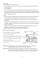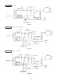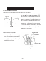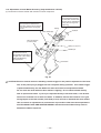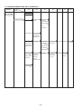
1
MODELS
C 10FCH2
C 10FCE2
Hitachi
Power Tools
C
COMPOUND MITER SAW
C 10FCH2
C 10FCE2
LIST Nos. C 10FCH2: E945
C 10FCE2: E946
TECHNICAL DATA
AND
SERVICE MANUAL
Oct. 2006
SPECIFICATIONS AND PARTS ARE SUBJECT TO CHANGE FOR IMPROVEMENT
REMARK:
Throughout this TECHNICAL DATA AND SERVICE MANUAL, a symbol(s)
is(are) used in the place of company name(s) and model name(s) of our
competitor(s). The symbol(s) utilized here is(are) as follows:
Competitor
Symbol Utilized
Company Name
Model Name
P
DEWALT
DW703
Q
RIDGID
MS1065LZ
CONTENTS
Page
1. PRODUCT NAME ........................................................................................................................... 1
2. MARKETING OBJECTIVE ............................................................................................................. 1
3. APPLICATIONS .............................................................................................................................. 1
4. SELLING POINTS .......................................................................................................................... 1
4-1. Selling Point Descriptions ............................................................................................................... 2
5. SPECIFICATIONS .......................................................................................................................... 4
6. COMPARISONS WITH SIMILAR PRODUCTS .............................................................................. 6
7. PRECAUTIONS IN SALES PROMOTION ..................................................................................... 7
7-1. Instruction Manual .......................................................................................................................... 7
7-2. Warning Labels and Caution Labels ............................................................................................... 7
7-3. Relative Standards ......................................................................................................................... 9
7-4. Laser Marker (Only the Model C 10FCH2) ..................................................................................... 9
7-5. Ambient Illuminance and Visibility of Laser Line (Only the Model C 10FCH2) ............................. 10
8. ADJUSTMENT AND OPERATION PRECAUTIONS ..................................................................... 11
8-1. Position Adjustment of Laser Line (Only the Model C 10FCH2) .................................................... 11
8-2. How to Use the Vise Assembly ..................................................................................................... 12
8-3. Confirmation for Use of Sub Fence (B) ......................................................................................... 13
8-4. Cutting Operation .......................................................................................................................... 14
9. ADJUSTMENT OF COMPONENTS ............................................................................................. 18
9-1. Bevel Angle Adjustment ................................................................................................................ 18
10. PACKING .................................................................................................................................... 18
11. PRECAUTIONS IN DISASSEMBLY AND REASSEMBLY ......................................................... 20
11-1. Precautions in Disassembly and Reassembly of the Laser Marker (Only the Model C 10FCH2) ....... 20
11-2. Disassembly ................................................................................................................................ 20
11-3. Reassembly ................................................................................................................................ 27
11-4. Wiring Diagram ........................................................................................................................... 28
11-5. No-load Current ........................................................................................................................... 34
11-6. Reassembly Requiring Adjustment ............................................................................................. 34
11-7. Lubrication ................................................................................................................................... 35
11-8. Product Precision ........................................................................................................................ 35
11-9. Adjustment of Laser Marker Accuracy (Only the Model C 10FCH2) ........................................... 36
11-10. Tightening Torque ...................................................................................................................... 39
12. REPAIR GUIDE .......................................................................................................................... 41
13. STANDARD REPAIR TIME (UNIT) SCHEDULES ..................................................................... 46
Assembly Diagram for C 10FCH2
Assembly Diagram for C 10FCE2
1. PRODUCT NAME
Hitachi Compound Miter Saw, Models C 10FCH2 and C 10FCE2
2. MARKETING OBJECTIVE
The new Models C 10FCH2 and C 10FCE2 are released as the upgraded versions of the current Models
C 10FCH and C 10FCE that are well reputed in the North American market. The Models C 10FCH2 and
C 10FCE2 are lighter than the current models for easy carrying. In addition, the sub fence for supporting large
stock is changed from the insertion type to the pivot type to improve operability in bevel cutting.
The Model C 10FCH2 is equipped with the same laser guide system as the current model for easy adjustment of
the cutting position or workpieces. With the new Models C 10FCH2 and C 10FCE2, we aim to enhance the share
of Hitachi compound miter saw series.
3. APPLICATIONS
Cutting various types of wood workpieces
Cutting workpieces of plywood, decoration panels, soft fiberboard and hard board
Cutting aluminum sashes
4. SELLING POINTS
(3) Soft vibration
reducing grip
(2) Aggressive tool design
(6) Powerful 15 amps motor
(for U.S.A. and Canada)
(4) Lightest weight in the class
C 10FCH2: 12 kg
C 10FCE2: 11.9 kg
(8) Dust guide to prevent
chips from scattering
(1) Laser guide system
For easier alignment with
the ink line
(Only Model C 10FCH2)
(7) Thumb actuated positive
stops for quick and easy
miter adjustment
Adjustable pivot fence
For supporting large stock
(5) Large table for increased
material stability
--- 1 ---
4-1. Selling Point Descriptions
(1) Laser guide system (Only the Model C 10FCH2)
Use the laser marker for aligning with the ink line on the
workpiece.
1
Cutting position can be properly adjusted by aligning the
positioning ink line with the laser line. There is no need to
Laser beam
make a long ink line on the workpiece.
2
There is no need to lower the motor head to align with the
ink line because the laser marker makes a laser line on the
workpiece. In addition, cutting position can be easily
adjusted because the operator can hold the workpiece with
both hands to move.
3
Cutting poisition can be easily adjusted because the laser
Fig. 1
line can be aligned with an optionally angled ink line.
4
Even the woekpieces such as crown moldings and base
Laser line
boards that have decorative surfaces and are difficult to be
made an ink line can be cut just by aligning the laser line
with the ink line on the fence side. The laser line is adjusted
to the width of the saw blade at the time of factory shipment.
Depending upon the user's cutting choice, the laser line can
be aligned with the left side of the cutting width (saw blade)
or the ink line on the right side. Adjust the position of the
laser line according to "8-1. Position Adjustment of Laser
Line" on page 11.
Ink line
Fig. 2
(2) Aggressive tool design
The tool color is gunmetallic silver to give a sturdier image. The circular saw portion is of a powerful, original
and aggressive design.
(3) Soft, vibration reducing grip
The handle grip is comfortable and slip-resistant thanks to the integrally molded rubber. In addition, it reduces
vibration transmitted to the operator's hand. The Models C 10FCH2 and C 10FCE2 are easier to operate.
(4) Lightest weight in 10" class
The Model C 10FCH2 weighs 12 kg (26.5 lbs.) and the Model C 10FCE2 weighs 11.9 kg (26.2 lbs.)
The Models C 10FCH2 and C 10FCE2 are the lightest compound miter saws in the 10" class.
--- 2 ---
(5) Large table for increased material stability
The turn table is as large as that of the Model C 10FCH.
Table 1
C 10FCH2/C 10FCE2
C 10FCH/C 10FCE
Outside diameter of turn table (mm)
280
280
(6) Powerful 15 amps motor (for U.S.A. and Canada)
The Models C 10FCH2 and C 10FCE2 are equipped with a 15-ampere motor. The Models C 10FCH2 and
C 10FCE2 can cut workpieces as quickly as the Model C 10FCH.
(7) Thumb actuated positive stops for quick and easy miter adjustment
The positive stops are provided to adjust the turn table position for miter cutting in the same manner as the
current Model C 10FCH. These stops can be also actuated (fixed or released) with thumb quickly and easily
holding the side handle.
(8) Dust guide to prevent chips from scattering
A dust guide is provided to prevent wood chips from adhering to the saw blade and scattering when cutting the
edge of the workpiece.
--- 3 ---
5. SPECIFICATIONS
Maximum
cutting
dimensions
Height x
Width
(H x W)
0û (Right angle)
59 mm (2-5/16") x 144 mm (5-21/32")
89 mm (3-1/2") x 101 mm (3-31/32")
Miter right/left 45û
59 mm (2-5/16") x 102 mm (4")
89 mm (3-1/2") x 70 mm (2-3/4")
Miter right/left 52û
59 mm (2-5/16") x 89 mm (3-1/2")
89 mm (3-1/2") x 54 mm (2-1/8")
Bevel left 45û
41 mm (1-5/8") x 144 mm (5-21/32")
Miter right/left 45û
+
Bevel left 45û
41 mm (1-5/8") x 102 mm (4")
Miter cutting ranges
Right and left 0û --- 52û
Bevel cutting ranges
Left 0û --- 45û
Compound (miter + left bevel)
cutting ranges
Miter: Right and left 0û --- 45û, Bevel: Left 0û --- 45û
Angle stopper positions
Right and left 0û, 15û, 22.5û, 31.6û, 45û
Saw blade outer diameter
255 mm (10") external dia.
Saw blade bore
Lower guard lock
USA/CAN
Europe
Asia/China
AUS/NZL
15.9 mm (5/8")
30 mm (1-11/64")
25.4 mm (1")
25.4 mm (1") and
30 mm (1-11/64")
Not provided
Provided
Not provided
Not provided
Maximum output
Laser
marker
Wave length
(Only Model
C 10FCH2) Laser medium
< 1 mW (CLASS II)
Power source type and voltage
AC single phase 50/60 Hz, 110 V, 120 V, 220 V --- 240 V
Type of motor
AC single phase commutator series motor
Full-load current
110 V --- 120 V: 15 A, 220 V: 7.5 A, 230 V: 7.2 A, 240 V: 6.9 A
No-load rotation speed
5,000 min-1
Max. output
1,950 W
Main unit dimensions
Width x Depth x Height
460 mm x 628 mm x 561 mm (18-1/8" x 24-3/4" x 22-3/32")
Weight
400 nm --- 700 nm
Laser diode
C 10FCH2
12 kg (26. 5 lbs.), gross weight 14.7 kg (32.5 lbs.)
C 10FCE2
11.9 kg (26. 2 lbs.), gross weight 14.6 kg (32.1 lbs.)
Coating
Gunmetallic silver
Packaging
Corrugated cardboard box
Cord
Type: 2-conductor cabtire cable
Length: 1.8 m (6 ft)
Standard accessories
255 mm (10") TCT saw blade (24 teeth, Code No. 318963)
for wood cutting (except for China, Europe)
255 mm (10") TCT saw blade (100 teeth, Code No. 319658)
for aluminum cutting (for China)
255 mm (10") TCT saw blade (30 teeth, Code No. 319107)
for wood cutting (for Europe)
Dust bag
Vise ass'y
10 mm box wrench
4 mm hex. bar wrench (only Model C 10FCH2)
Sub fence (Pivot type)
• • • • • • • • • • • • • • •
• • • • • • • • • • • • • • •
• • • • • • • • • • • • • • •
--- 4 ---
Optional accessories
255 mm (10") TCT saw blade (60 teeth, Code No. 976472)
for normal cutting
255 mm (10") TCT saw blade (100 teeth, Code No. 319658)
for aluminum cutting
Extension holder and stopper (Code No. 322710)
Crown molding vise ass'y (Code No. 322712)
(including crown molding stopper (L))
Crown molding stopper (L) (Code No. 322713)
Crown molding stopper (R) (Code No. 322714)
•••••••••••••••
• • • • • • • • • • • • • • •
--- 5 ---
6. COMPARISONS WITH SIMILAR PRODUCTS
Maker/Model
Item
P
Q
59 mm x 144 mm
(2-5/16" x 5-21/32")
89 mm x 101 mm
(3-1/2" x 3-31/32")
59 mm x 102 mm
(2-5/16" x 4")
Right and left 52û
59 mm x 89 mm
(2-5/16" x 3-1/2")
59 mm x 144 mm
(2-5/16" x 5-21/32")
89 mm x 101 mm
(3-1/2" x 3-31/32")
59 mm x 144 mm
(2-5/16" x 5-21/32")
89 mm x 101 mm
(3-1/2" x 3-31/32")
59 mm x 144 mm
(2-5/16" x 5-21/32")
89 mm x 101 mm
(3-1/2" x 3-31/32")
59 mm x 102 mm
(2-5/16" x 4")
Right and left 52û
59 mm x 89 mm
(2-5/16" x 3-1/2")
59 mm x 102 mm
(2-5/16" x 4")
Right and left 52û
59 mm x 89 mm
(2-5/16" x 3-1/2")
59 mm x 102 mm
(2-5/16" x 4")
Right and left 50û
59 mm x 89 mm
(2-5/16" x 3-1/2")
Bevel left 45û
41 mm x 144 mm
(1-5/8" x 5-21/32")
41 mm x 144 mm
(1-5/8" x 5-21/32")
41 mm x 144 mm
(1-5/8" x 5-21/32")
41 mm x 144 mm
(1-5/8" x 5-21/32")
Miter right/left 45û
+
Bevel left 45û
41 mm x 102 mm
(1-5/8" x 4")
41 mm x 102 mm
(1-5/8" x 4")
41 mm x 102 mm
(1-5/8" x 4")
41 mm x 102 mm
(1-5/8" x 4")
Right and left 0û--- 52û
Right and left 0û--- 52û
Right and left 0û--- 52û
Right and left 0û--- 50û
Left 0û--- 45û
Miter: Right and left
0û --- 45û
Bevel: Left 0û --- 45û
Right and left 0û, 15û,
22.5û, 31.6û, 45û
Left 0û--- 48û
Miter: Right and left
0û --- 45û
Bevel: Left 0û --- 45û
Right and left 0û, 15û,
22.5û, 31.6û, 45û
Left 0û--- 48û
Miter: Right and left
0û --- 45û
Bevel: Left 0û --- 45û
Right and left 0û,11.3û,
15û, 22.5û, 31.6û, 45û
0û (Right angle)
Max.
cutting
dimensions
Height
x Width
(H x W)
HITACHI
HITACHI
C 10FCH2/C 10FCE2 C 10FCH/C 10FCE
Miter right/left 45û
Miter cutting ranges
Bevel cutting ranges
Compound (miter + left bevel)
cutting ranges
Angle stopper position
Left 0û--- 45û
Miter: Right and left
0û --- 45û
Bevel: Left 0û --- 45û
Right and left 0û, 15û,
22.5û, 31.6û, 45û
255 (10")
255 (10")
254 (10")
254 (10")
No-load revolution (min-1)
5,000
5,000
5,000
5,500
Not provided
Provided
5 mW
Double insulation
Motor
Saw blade outer diameter (mm)
Power input (W)
Max. output (W)
Laser marker
Laser output
Insulation structure
Turn table outer diameter (mm)
Debris guard
Dust bag size (mm)
Main unit dimensions
Width x Depth x Height
Product weight (kg)
Standard accessories
Optional accessories
1,520
1,520
1,950
1,950
C 10FCH2 C10FCE2 C 10FCH
C10FCE
Provided Not provided Provided Not provided
1 mW
1 mW
Double insulation
Double insulation
280 (11-1/32")
280 (11-1/32")
290 (11-27/64")
297 (11-11/16")
Provided (fixed)
250 x 160
Provided (fixed)
250 x 160
None
None
245 x 190
(9-27/32" x 6-5/16")
(9-27/32" x 6-5/16")
460 x 628 x 561
460 x 628 x 561
Double insulation
(9-21/32" x 6-15/32")
510 x 630 x 565
530 x 540 x 565
(18-1/8" x 24-3/4" x 22-3/32") (18-1/8" x 24-3/4" x 22-3/32") (20-3/32" x 24-13/16" x 22-1/4") (20-7/8" x 21-1/4" x 22-1/4")
C 10FCH2 C 10FCE2
C 10FCH
C 10FCE
12 (26.5 lbs.) 11.9 (26.2 lbs.) 13.3 (29.3 lbs.) 13.2 (29.1 lbs.)
14.7 (32.4 lbs.)
14.8 (32.6 lbs.)
• 255 mm (10") TCT saw
• 255 mm (10") TCT saw • 254 mm (10") carbide
• 254 mm (10") saw blade
blade (24 teeth) for
wood cutting
• Dust bag
• Vise ass'y
• 10 mm box wrench
• 4 mm hex. bar wrench
(only Model C 10FCH2)
• Sub fence
• 255 mm (10") TCT saw
blade (60 teeth) for
normal cutting
• 255 mm (10") TCT saw
blade (100 teeth) for
aluminum cutting
• Extension holder and
stopper
• Crown molding vise ass'y
(including crown molding
stopper (L))
• Crown molding stopper (L)
• Crown molding stopper (R)
blade (24 teeth) for
wood cutting
• Dust bag
• Vise ass'y
• 10 mm box wrench
• 4 mm hex. bar wrench
(only Model C 10FCH)
• Sub fence
• 255 mm (10") TCT saw
blade (60 teeth) for
normal cutting
• 255 mm (10") TCT saw
blade (100 teeth) for
aluminum cutting
• Extension holder and
stopper
• Crown molding vise ass'y
(including crown molding
stopper (L))
• Crown molding stopper (L)
• Crown molding stopper (R)
• Dust bag
• Dust guide
• Vise ass'y
• Blade wrench
• 6 mm hex. bar wrench
• 8 mm hex. bar wrench
--- 6 ---
blade (40 teeth)
• Dust bag
• Blade wrench
• Extension holder and
stopper
• Vise ass'y
• Crown molding stopper
7. PRECAUTIONS IN SALES PROMOTION
In the interest of promoting the safest and most efficient use of the Models C 10FCH2 and C 10FCE2 Compound
Saws by all of our customers, it is very important that at the time of sale the salesperson carefully ensures that the
buyer seriously recognizes the importance of the contents of the Instruction Manual, and fully understands the
meaning of the precautions listed on the Warning Labels and Caution Labels attached to each machine.
7-1. Instruction Manual
Although every effort is made in each step of design, manufacture and inspection to provide protection against
safety hazards, the dangers inherent in the use of any compound saw cannot be completely eliminated.
Accordingly, general precautions and suggestions for the use of electric power tools, and specific precautions and
suggestions for the use of the compound saw are listed in the Instruction Manual to enhance the safe, efficient
use of the tool by the customer. Salespersons must be thoroughly familiar with the contents of the Instruction
Manual to be able to offer appropriate guidance to the customer during sales promotion.
7-2. Warning Labels and Caution Labels
(1) Precautions on the name plate
Each Model C 10FCH2/FCE2 is furnished with a Name Plate that lists the following precautions.
USA/CAN
Fig. 3-1
Europe
Fig. 3-2
AUS/NZL/China/Asia
Fig. 3-3
Instruct the customer to thoroughly read the Instruction Manual prior to attempting to operate the machine.
--- 7 ---
(2) Caution label (A) (at the front of the hinge) (only the Model C 10FCH2)
Do not stare into laser beam. If your eye is exposed directly to the laser beam, it can be hurt. Caution label
(A) is adhered to each machine to comply with the standards for the safe use of laser equipment.
Caution label (A) (at the front of the hinge) (only the Model C 10FCH2)
Fig. 4
(3) Warning label (at the front of sub fence (B))
Fig. 5
(4) Caution label (F) (at the front of link (A)) (for Europe)
Fig. 6
--- 8 ---
7-3. Relative Standards
Standards, regulations and guidelines for the safe use of laser equipment
[USA] FDA CDRH 21 CFR
[AUS/NZL] AS/NZS 2211.1: 2001
[Europe] EN 60825-1: 2001-11
7-4. Laser Marker (Only the Model C 10FCH2)
The Model C 10FCH2 is equipped with the laser marker that complies with the Class II requirements of the
standard specified in "7-3. Relative Standards". The Class II laser is defined as follows:
The laser power is low and it is safe by the protective measures such as blinking. However, it is dangerous if
the operator's eyes are exposed directly to the laser for a protracted period.
The operator can use the laser equipment without particular training and instruction.
The amount of light exposure (output) is 1 mW or less at the position where the operator can be exposed to
the laser radiation during operation. (This is in the case of the U.S.A. The measuring methods and the output
values are different depending on the standards.)
The saw blade unit prevents access of the operator's eye to the laser emitting aperture less than 65 mm.
In addition, the amount of light exposure (output) is 1 mW or less (about 0.4 mW) at this position. Thus the Model
C 10FCH2 satisfies the Class II requirements adequately. There is no ill effect on the operator's body if looking at
the laser line on the workpiece during operation.
CAUTION (1) Be sure to disconnect the power cord plug from the receptacle before removing the
laser marker for repair. If it is unavoidable to check the operation of the removed laser
marker with the power turned on, face the laser emitting aperture to the ground to show
the laser line on the ground.
(2) Laser radiation when open. DO NOT STARE INTO BEAM OR VIEW DIRECTLY WITH
OPTICAL INSTRUMENTS.
The lilfespan of the laser marker in the Model C 10FCH2 is about 2,160 hours. (About three years: 4 hours of
use/day x 180 days/year)
--- 9 ---
7-5. Ambient Illuminance and Visibility of Laser Line (Only the Model C 10FCH2)
The visibility of the laser line on the workpiece changes depending on the brightness of the working environment.
Instruct the customer to consider the brightness of the working environment when using the laser marker referring
to the following table.
Table 2 Ambient illuminance and visibility of laser line
Illuminance (lux)
Outdoor
Ambient
conditions
(reference)
Laser line
3000 or more 3000 or more 3000 - 2500
Shaded area
in cloudy
weather
Under direct
Shaded area Cloudy
sunlight of fine
in fine weather weather
weather
Near the
Indoor under
window under
fine weather
fine weather
Indoor
Invisible
Visible
800 - 600
300 - 200
Near the
window under Indoor under
cloudy
cloudy
weather
weather
Visible
Visible
150 - 80
Just before the
sunset in
cloudy
weather
Visible
Near the window
under cloudy
weather, just
before the
sunset
Glaring
30 or less
Ink line is
invisible.
Glaring
(The working environment where the illuminance is 200 luxes or less is dark and difficult to operate the Model
C 10FCH2.)
The laser line is invisible under direct sunlight of fine weather. Prepare a shaded area or relocate to a shaded
area to operate the Model C 10FCH2.)
--- 10 ---
8. ADJUSTMENT AND OPERATION PRECAUTIONS
8-1. Position Adjustment of Laser Line (Only the Model C 10FCH2)
Saw blade
Workpiece
The laser line is adjusted to the width of the saw blade at the time
of factory shipment. Depending upon the cutting choice, align the
laser line with the left side of the cutting width (saw blade) or the
Ink line
right side according to the following procedure. First, make a rightCutting width
angle ink line on the workpiece that is about 38 mm (1-1/2") in
height and 89 mm (3-1/2") in width. To cut the right side of the ink
Fig. 7
line with the saw blade as shown in Fig. 7, align the left side of the
4 mm hex.
bar wrench
saw blade with the ink line on the workpiece and make a groove of
Laser line
about 5 mm deep on the workpiece to the middle. Hold the
grooved workpiece by the vise as it is and do not move it.
Light up the laser marker. Then insert a 4 mm hex. bar wrench in
Turn
Move
the 12 diameter hole on the side of the gear case, turn the hex.
socket set screw to move the laser line. (If you turn the hex. socket
screw clockwise, the laser line will shift to the right and if you turn it
counterclockwise, the laser line will shift to the left.) (Fig. 8)
Groove
Fig. 8
Thus the cutting position matches the laser line position. Align the
ink line on the workpiece with the laser line. When aligning the ink
Laser line
line, slide the workpiece little by little and secure it by vise at a
position where the laser line overlaps with the ink line (Fig. 9).
Work on grooving again and check the position of the laser line.
When the ink line and the laser line are overlapped, the strength
and weakness of light will change, resulting in a stable cutting
operation because you can easily discern the conformity of lines.
Ink line
This ensures the minimum cutting errors.
Fig. 9
WARNING:
Before plugging the power plug into the receptacle, make sure that the main body and the laser
marker are turned off.
Exercise utmost caution in handling the switch trigger for the position adjustment of the laser line,
as the power plug is plugged into the receptacle during operation. If the switch trigger is pulled
inadvertently, the saw blade can rotate and result in unexpected accidents.
Do not remove the laser marker to use for other purposes.
--- 11 ---
CAUTION:
Laser radiation - Do not stare into beam.
Laser radiation on work table. Do not stare into beam. If your eye is exposed directly to the laser
beam, it can be hurt.
Do not dismantle it.
Do not give strong impact to the laser marker (main body of tool); otherwise, the position of a laser
line can go out of order, resulting in the damage of the laser marker as well as a shortened service life.
Keep the laser marker lit only during a cutting operation. Prolonged lighting of the laser marker can
result in a shortened service life.
NOTE:
Perform cutting by overlapping the ink line with the laser line. When the ink line and the laser line
are overlapped, the strength and weakness of light will change, resulting in a stable cutting
operation because you can easily discern the conformity of lines. This ensures the minimum
cutting errors.
In outdoor or near-the-window operations, it may become difficult to observe the laser line due to
the sunlight. Under such circumstances, move to a place that is not directly under the sunlight and
engage in the operation.
Do not tug on the cord behind the motor head or hook your finger, wood and the like around it;
otherwise, the cord may come off and the laser marker may not light.
Instruct the above precautions on the laser marker to the customers.
8-2. How to Use the Vise Assembly
6 mm wing
bolt (B)
(1) The vise assembly can be mounted on either the left
Screw holder
Knob
fence (fence (B)) or the right fence (fence (A)) by
Vise plate
loosening 6 mm wing bolt (A).
(2) The screw holder can be raised or lowered according to
the height of the workpiece by loosening 6 mm wing bolt
Fence
Vise shaft
(B). After the adjustment, firmly tighten 6 mm wing bolt
(B) and fix the screw holder.
(3) Turn the upper knob and securely fix the workpiece in
position (Fig. 10).
6 mm wing
bolt (A)
Workpiece
Fig. 10
WARNING: Always firmly clamp or vise to secure the workpiece to the fence; otherwise the
workpiece might be thrust from the table and cause bodily harm.
CAUTION: Always confirm that the motor head does not contact the vise assembly when it is
lowered for cutting. If there is any danger that it may do so, loosen 6 mm wing bolt (B)
and move the vise assembly to a position where it will not contact the saw blade.
--- 12 ---
8-3. Confirmation for Use of Sub Fence (B)
The Models C 10FCH2 and C 10FCE2 are equipped with
Left bevel cutting
Turn.
Miter cutting
Right bevel cutting
sub fence (B). Use sub fence (B) for miter cutting and
right bevel cutting. Sub fence (B) supports the workpiece
widely for stable cutting. In the case of left bevel cutting,
Sub fence
raise sub fence (B) as illustrated in Fig. 11 and turn it
Fence (B)
counterclockwise.
WARNING: In the case of left bevel cutting, turn sub fence (B)
Fig. 11
counterclockwise. Unless it is turned counterclockwise, the main body or saw blade may
contact the sub fence, resulting in an injury. Be sure to instruct the customers to turn sub
fence (B) counterclockwise in the case of left bevel cutting.
--- 13 ---
8-4. Cutting Operation
(1) Cutting efficiency will be reduced if a dull saw blade is used, if an excessively long extension cord is used, or if
the wire gauge of the extension cord is too small. (For details on extension cords, please refer to the
Instruction Manual.) This is particularly important when cutting materials with dimensions which are at or near
the maximum capacity for the machine.
(2) The customer should be advised to thoroughly inspect the workpiece to ensure that there are no metallic
objects (nails in particular), sand, or other foreign matter in or on the workpiece. Saw blade contact with such
foreign matter will not only shorten the service life of the saw blade, but could cause serious accident. Should
the saw blade tips be broken off, the tips may fly toward the operator.
(3) Direct current cannot be used. The switch can be faulty if used.
(4) Press cutting
Like the Model C 10FCH, the Models C 10FCH2 and C 10FCE2 can be used for press cutting of workpieces
up to 59 mm x 144 mm (2-1/4" x 5-5/8") in a single operation by simply pushing the saw blade section (head)
downward. The customer should be cautioned that excessive pressure on the handle will not increase the
cutting speed. On the contrary, excessive pressure may result in reduced cutting efficiency (irregular or rough
cutting of the workpiece), and could also cause overload and subsequent burnout of the motor.
On completion of the cutting operation, turn the switch OFF and wait for the saw blade to come to a complete
stop before raising the saw blade section (head) to its original position. Raising the saw blade section (head)
while the saw blade is rotating may cause unwanted cutting marks on the workpiece.
Techniques to avoid unwanted cutting marks
Uneven and unwanted cutting marks can be avoided throughout the cutting operation by gently and smoothly
pressing down on the handle, so that the entire cutting operation is accomplished in a single uninterrupted
motion.
(5) Miter cutting
Miter cutting is accomplished by turning the table. (For details, please refer to the Instruction Manual.)
(6) Bevel cutting
Bevel cutting of 0 --- 45û to the left is accomplished by inclining the saw blade section (head). (For details,
please refer to the Instruction Manual.)
CAUTION: When the workpiece is secured on the left side,
the cut-off portion comes to rest on the side of the
saw blade as illustrated in Fig. 12. If the handle is
Fixed-side workpiece
Cut-off-side
workpiece
raised before the saw blade rotation comes to a
complete stop, there is a chance that the cut-off
portion of the workpiece could become jammed
against the saw blade, causing a hazardous
condition. Instruct the customer to ensure
Saw blade
without fail that the saw blade comes to a complete
stop before attempting to raise the handle.
--- 14 ---
Fig. 12
(7) Compound (miter + bevel) cutting
Compound cutting can be accomplished by combining the miter cutting and bevel cutting operations described
in paragraphs (4) and (5) above. (For details, please refer to the Instruction Manual.) When the saw blade
section (head) is inclined 45û to the left, the table can be turned up to 45û to the right and left.
(8) Crown molding cutting
This machine can cut two types of crown molding workpieces by combining the miter and bevel cutting
operations (for USA).
Figure 13 shows two common crown molding types having angles of (θ) 38û and 45û. For the typical crown
molding fittings, see Fig. 14.
A Upper surface ceiling
θû
Ceiling
Wall
B Lower surface
1
Wall
2
3
4
Outside corner
Inside corner
Fig. 14
Fig. 13
The table below shows the miter angle and the bevel angle settings that are ideal for the two crown molding
types.
NOTE: For convenience, positive stops are provided for both the miter setting and the bevel setting
(left and right 31.6û) positions.
For miter cut setting
If the turn table has been set to either of the angles described, move the turn table adjusting side handle a
little to the right and left to stabilize the position and to properly align the miter scale and the tip of the
indicator before the operation starts.
For bevel cut setting
Move handle on miter section to the right and left and check that the position is stable and the angle scale
and the tip of the indicator are properly aligned. Then tighten the clamp lever.
Table 3
Type of
crown molding
To process crown molding at
positions 1 and 4 in Fig. 14
To process crown molding at
positions 2 and 3 in Fig. 14
Miter angle
setting
Miter angle
setting
Bevel angle
setting
Bevel angle
setting
45û type
Right 35.3û
( mark)
Left 30û
( mark)
Right 30û
( mark)
Left 35.3û
( mark)
Left 30û
( mark)
Right 30û
( mark)
38û type
Right 31.6û
( mark)
Left 33.9û
( mark)
Right 33.9û
( mark)
Left 31.6û
( mark)
Left 33.9û
( mark)
Right 33.9û
( mark)
--- 15 ---
(1) Setting to cut crown molding at positions 1 and 4 in Fig. 14 (See Fig. 15, tilt the head to the left.):
1 Turn the turn table to the right and set the miter angle as follows:
For 45û type crown moldings: 35.3û ( mark)
For 38û type crown moldings: 31.6û ( mark)
2 Turn the head to the left and set the bevel angle as follows:
For 45û type crown moldings: 30û ( mark)
For 38û type crown moldings: 33.9û ( mark)
3 Position the crown molding so that the lower surface ( A in Fig. 13) contacts the fence as indicated in
Fig. 17.
(2) Setting to cut crown moldings at positions 2 and 3 in Fig. 14 (See Fig. 16, tilt the head to the left.):
1 Turn the turn table to the left and set the miter angle as follows:
For 45û type crown moldings: 35.3û ( mark)
For 38û type crown moldings: 31.6û ( mark)
2 Tilt the head to the left and set the bevel angle as follows:
For 45û type crown moldings: 30û ( mark)
For 38û type crown moldings: 33.9û ( mark)
3 Position the crown molding so that the lower surface ( B in Fig. 13) contacts the fence as indicated in
Fig. 18.
Head
Head
Bevel angle scale
1
Bevel angle scale
3
4
2
Fence
Fence
Miter angle scale
Base
Turn table
Base
Turn table
Miter angle scale
Fig. 15
Fig. 16
Fence
Fence
A
B
A
B
Table on base
Table on base
Fig. 18
Fig. 17
--- 16 ---
Cutting method of crown molding without tilting the saw blade
Crown molding
vise ass'y
(optional
accessory)
Crown molding stopper (R)
(1) Crown molding stoppers (L) and (R) (optional
(optional accessory)
6 mm wing bolt
accessories) allow easier cuts of crown molding without
tilting the saw blade. Install them to both sides of the
base as shown in Fig. 19. After inserting, tighten the
6 mm wing
bolt
6 mm knob bolts to secure the crown molding guides.
[ Optional accessories used ]
Crown molding vise ass'y
6 mm wing bolt
(including crown molding stopper (L))
Crown molding stopper (L)
(optional accessory)
Crown molding stopper (L)
Crown molding stopper (R)
Fig. 19
Crown molding vise ass'y
(optional accessory)
(2) The crown molding vise ass'y (optional accessory) can
be mounted on either the left fence (fence (B)) or the
6 mm knob bolt
right fence (fence (A)). It can unite with the slope of the
Knob
crown molding and vise can be pressed down. Then
turn the upper knob, as necessary, to securely attach
Fence
the crown molding in position. To raise or lower the vise
assembly, first loosen the 6 mm knob bolt.
6 mm wing bolt
Crown molding
Crown molding stopper (L)
Crown molding stopper (R)
(optional accessories)
Fig. 20
After adjusting teh height, firmly tighten the 6 mm wing boltl; then turn the upper knob, as necessary, to
securely attach the crown molding in position. (See Fig. 20)
WARNING: Always firmly clamp or vise to secure the crown molding to the fence; otherwise the
crown molding might be thrust from the table and cause bodily harm. Do not perform
bevel cutting. The main body or saw blade may contact the sub fence, resulting in an
injury.
CAUTION: Always confirm that the motor head does not contact the crown molding vise ass'y
when it is lowered for cutting. If there is any danger that it may do so, loosen the 6 mm
knob bolt and move the crown molding vise ass'y to a position where it will not contact
the saw blade.
Position crown molding with its WALL CONTACT EDGE against the guide fence and its CEILING CONTACT
EDGE against the crown molding stoppers as shown in Fig. 20. Adjust the crown molding stoppers according
to the size of the crown molding. Tighten the 6 mm wing bolt to secure the crown molding stoppers.
--- 17 ---
9. ADJUSTMENT OF COMPONENTS
9-1. Bevel Angle Adjustment
Before the power tool is shipped from the factory, it is adjusted for 0û and left 45û bevel cutting angles.
The positioning and bevel cutting angle can be adjusted by changing the height of the 8 mm nylock bolt
(maximum bevel cutting angle is 48û).
Indicator
(For bevel scale)
8 mm nylock bolt
(stopper for 0û)
8 mm nylock bolt
(stopper for left
45û bevel angle)
Fig. 21
Fig. 22
10. PACKING
(1) Place the base packing in the carton box.
(2) Preparation before packing
Turn the turn table 52û clockwise. Tilt the gear case 25û. Set the clamp lever to the position as shown in
Fig. 23. Remove the side handle. Fix the turn table with the bolt M10 x 35.
(3) Mounting packing (D)
Place packing (D) under the gear case and swing the motor section. Pressing on packing (D), hook the
stopper pin on the gear case.
(4) Mounting packing (C)
Pressing Packing (C) against the top of the base, side of fence (B) and side of the gear case, place the main
body in the carton box.
(5) Mounting packing (F)
Fold packing (F) in two at the center and insert it between the gear case and protective cover (A).
(6) Mounting packings (B) and (A)
Place the base packing in the carton box and place the power tool on it. Fit packing (B) on the housing.
Place packing (A) at the left of the base.
(7) Mounting packing (E)
Place packing (E) on the gear case. Close the carton box.
--- 18 ---
Clamp lever
Fig. 23
Packing (B)
Packing (F)
Packing (D)
Bolt M10 x 35
Side handle
Packing (C)
Fig. 24
Fig. 25
Packing (E)
Packing (A)
Packing (B)
Packing (C)
Carton box
Packing (F)
Base packing
Fig. 26
--- 19 ---
11. PRECAUTIONS IN DISASSEMBLY AND REASSEMBLY
11-1. Precautions in Disassembly and Reassembly of the Laser Marker (Only the Model C 10FCH2)
Do not stare into the laser emitting aperture during disassembly and reassembly of the laser marker. Do not
observe beam directly with an optical instrument. Use of controls or adjustments or performance of procedures
other than those specified in this TECHNICAL DATA AND SERVICE MANUAL and the Instruction Manual may
result in hazardous radiation exposure.
11-2. Disassembly
Special attention in disassembly should be given to the following items. The circled numbers in the figures and
the [Bold] numbers in the descriptions below correspond to the item numbers in the pars list and exploded
assembly diagram of the Model C 10FCH2. For the Model C 10FCE2, refer to the parts list separately.
Be sure to first disconnect the power plug when performing disassembly or replacement of the saw blade.
A. Turn table and base
Tools required:
• Phillips screwdriver
• Flat-blade screwdriver
• Box wrench 13 mm
• Box wrench 19 mm
Fig. 27
--- 20 ---
1. Remove the four Bolts M8 x 35 [46], Spring Washers M8 [47] and Bolt Washers M8 [48], then remove Fence
(A) [65] and Fence (B) [54].
2. Loosen the Clamp Lever [5] and remove the Machine Screw (W/Washers) M6 x 20 (Black) [4]. Turn the Bolt
(Left Hand) M10 [6] and remove it from the Hinge [16].
3. Remove Shaft (D) [13] and remove the Hinge [16] from the Turn Table [36].
4. Remove Table Insert (A) [33] and Table Insert (B) [32] from the Turn Table [36] by removing each fixing screw.
Remove the Side Handle [37] to remove the Spring Plate [59] from the Turn Table [36].
5. Remove the Nylon Nut M8 [28] and remove the Turn Table [36] from the Base Ass'y [67].
--- 21 ---
B. Armature ass'y
Cord, stator ass'y and housing ass'y
Tools required:
• Phillips screwdriver
• Flat-blade screwdriver
• Plastic hammer
• Nipper
Fig. 28
--- 22 ---
1. Remove the two Tapping Screws (W/Flange) D4 x 25 (Black) [151] and the four Tapping Screws (W/Flange)
D4 x 20 (Black) [152], then remove the Switch Handle [153].
2. Remove the wire of the Laser Holder [1] from the Switching Power Supply [157]. (Only the Model C 10FCH2)
3. Remove the Brush Cap [183] and the Carbon Brush [182].
4. Remove the four Machine Screws (W/Washers) M5 x 40 (Black) [178]. Then the Housing Ass'y [179] can be
removed from the Gear Case [123] together with the Switch Handle [153]. The Lock Lever [173] and the
Armature Ass'y [168] can also be removed.
5. Cut the internal wires at the root of the Cord [154] to disconnect the Cord [154] and the Stator Ass'y [176].
Otherwise, the internal wires become short and they cannot be wired in the reassembly work. (See "11-4.
Wiring Diagram" for detail.)
6. Remove the Tapping Screw (W/Flange) D4 x 16 [162]. Then remove the Cord Clip [163], Cord [154] and Cord
Armor D10.7 [155].
7. Remove the two Hex. Hd. Tapping Screws D5 x 50 [175] to remove the Brush Terminal [177] from the Brush
Holder [181]. Gently tap the surface of the Housing Ass'y [179] where the Gear Case [123] was mounted with
a plastic hammer to remove the Stator Ass'y [176].
--- 23 ---
C. Safety cover and link
Spindle and spring
Tools required:
• Phillips screwdriver
• Hex. bar wrench 4 mm
• Hex. bar wrench 3 mm
• Box wrench 10 mm (standard accessory)
• Plastic hammer
Fig. 29
--- 24 ---
1. Remove the Machine Screw M4 x 8 [131] at the notched side of the Spindle Cover [130] and slide the Spindle
Cover [130] to remove the TCT Saw Blade 255 mm [102] in the next step.
2. Remove the Bolt (Left Hand) W/Washer M7 x 17.5 [100] using the box wrench 10 mm (standard accessory).
Then Washer (D) [101], TCT Saw Blade 255 mm [102] and the other Washer (D) [101] can be removed in this
order.
3. Remove Special Screw (C) M5 [145] and Special Screw M6 [132], then remove the Link [184].
4. Remove the three Machine Screws M4 x 8 [139] and remove the lower guard ass'y from the Gear Case [123].
5. Remove the two Machine Screws (W/Sp. Washer) M5 x 16 [111]. Slightly tap the Gear Case [123] with a
plastic hammer to remove the Spindle Ass'y [104].
6. Remove the two Tapping Screws (W/Flange) D4 x 25 (Black) [151] and the four Tapping Screws (W/Flange)
D4 x 20 (Black) [152], then remove the Switch Handle [153]. Remove the wire of the Laser Holder [1] from
the Switching Power Supply [157]. (Only the Model C 10FCH2)
7. Remove the Hex. Socket Hd. Bolt M5 x 10 [115]. Note that the Gear Case [123] moves upward when the Hex.
Socket Hd. Bolt M5 x 10 [115] is removed because the Hex. Socket Hd. Bolt M5 x 10 [115] acts as an upper
limit stopper of the Gear Case [123].
8. Remove the Seal Lock Hex. Socket Set Screw M6 x 10 [3]. Holding the Gear Case [123], slightly tap Shaft (C)
[15] to remove it. Then the Spring [10] can be removed.
D. Vise ass'y
Tool required:
• Phillips screwdriver
1. Remove the Wing Bolt M6 x 15 [40] to remove the Vise Shaft [45].
2. Remove the Machine Screw M4 x 10 [44] to remove the Vise Plate [43].
3. Remove the Knob Bolt M10 x 66 [39] from the Screw Holder [41].
Fig. 30
--- 25 ---
E. Laser marker
Tools required:
• Phillips screwdriver
• Hex. bar wrench 4 mm
• Hex. bar wrench 3 mm
• Long-nose pliers
Fig. 31
1. Remove the two Tapping Screws (W/Flange) D4 x 25 (Black) [151] and the four Tapping Screws (W/Flange)
D4 x 20 (Black) [152], then remove the Switch Handle [153]. Remove the wire of the Laser Holder [1] from
the Switching Power Supply [157]. (Only the Model C 10FCH2)
2. Remove the Machine Screw M4 x 8 [114] and the Nylon Clip [112].
3. Remove the two Machine Screws (W/Washers) M5 x 16 [23] and remove the Dust Guide Ass'y [22] from the
Hinge [16].
4. Remove the two Hex. Socket Hd. Bolts M6 x 20 [17] and remove the Laser Holder [1] from the Hinge [16].
--- 26 ---
11-3. Reassembly
Reassembly can be accomplished by following the disassembly procedures in reverse. However, special
attention should be given to the following items.
(1) Prior to reassembly, measure the insulation resistance of the armature, stator, switch and other electrical
components and confirm that the insulation resistance of each part is more than 5 M Ω.
(2) When replacing the Spring [10], apply 5 grams of Hitachi Motor Grease to the inner circumference of the new
Spring [10] prior to reassembly.
(3) When replacing Liner (A) [56] and Liner (C) [57], apply Hitachi Motor Grease to the sliding surface of the Base
Ass'y [67] prior to reassembly.
(4) When replacing Liner (B) [18], apply 5 grams of Hitachi Motor Grease to the sliding surface of the Turn Table
[36] prior to reassembly.
(5) Be careful not to pinch Liner (C) [57] when mounting the Turn Table [36] to the Base Ass'y [67].
--- 27 ---
11-4. Wiring Diagram
Carefully ensure that wiring is accomplished as illustrated below. As incorrect wiring will result in lack of rotation,
reverse rotation or other malfunctions, close attention is absolutely necessary.
WARNING: Be sure to turn off the Switch (W/Cover) [165] on the side of the switch handle and unplug
the power cord plug from the receptacle before replacing the Laser Holder [1] and the
Switching Power Supply [157]. Do not stare into beam while the laser marker is lighting.
1
Wiring diagram
C 10FCH2 USA/CAN
Fig. 32-1
--- 28 ---
C 10FCH2 Europe (230 V areas)/AUS
Fig. 32-2
C 10FCH2 Europe (110 V areas)
Fig. 32-3
--- 29 ---
C 10FCE2 USA/CAN
Fig. 33-1
C 10FCE2 Europe (230 V areas)/AUS
Fig. 33-2
C 10FCE2 Europe (110 V areas)
Fig. 33-3
--- 30 ---
C 10FCE2 Asia/South America
Fig. 33-4
--- 31 ---
2
Actual wiring diagram
C 10FCH2 USA/CAN
Fig. 34-1
C 10FCH2 Europe/AUS/NZL/China/Hong Kong
Fig. 34-2
--- 32 ---
C 10FCE2 USA/CAN
Fig. 35-1
C 10FCE2 Europe/AUS/NZL/Asia/South America
Fig. 35-2
--- 33 ---
11-5. No-load Current
After no-load operation for 30 minutes, the no-load current values should be as follows.
Voltage, frequency
No-load current
110 V, 120 V
7 0.8 A
220 V, 230 V
4.3 0.5 A
240 V
4.0 0.5 A
11-6. Reassembly Requiring Adjustment
(1) Adjustment of squareness between the saw blade (dummy disc) and the fences
After disassembly or replacement of the Base Ass'y [67],
Turn Table [36], Fence (A) [65], Fence (B) [54] or Hinge
Fence (B)
Fence (A)
[16], it is necessary to perform adjustment to ensure that
the fences are positioned at precise right angles with
relation to the saw blade (or dummy disc). Align fence (B)
with the saw blade (or dummy disc), and adjust them as
Square
Saw blade or
dummy disc
necessary to ensure squareness (tolerance: 0.4/100 mm).
As shown in Fig. 36, use a square to set fence (B) square
to the saw blade. Next, use a straight edge to adjust fence
Fig. 36
(A) so that it is exactly aligned with fence (B). Finally, use
the square to confirm squareness of fence (A) with the saw
blade (tolerance: 0.4/100 mm).
Nylon Nut M8 [28]
(2) Reassembly of the Turn Table [36]
When reassembling the Turn Table [36] and the
Turn Table [36]
Base Ass'y [67], tighten the Nylon Nut M8 [28] so
that the Turn Table [36] turns smoothly without
A
excessive play or vibration. During reassembly,
liberally apply grease (Hitachi Motor Grease) at
the point marked "A" in Fig. 37.
Base Ass'y [67]
Shaft (B) [66]
Fig. 37
--- 34 ---
11-7. Lubrication
Advise the customer to lubricate the machine as indicated below at least once a month. Also, prior to applying
lubrication, any sawdust, dirt or other foreign matter should be thoroughly wiped away with a soft cloth.
(1) Swiveling section of the Gear Case [123] and the Hinge [16]
Coat the swiveling and sliding portion of the Gear Case [123] and the Hinge [16] with machine oil.
(2) Vise ass'y section
Coat the screw thread portion of the Knob Bolt M10 x 66 [39] of the Vise Ass'y [38] with machine oil.
(3) Swiveling section of the Turn Table [36] and the Hinge [16]
Coat the swiveling and sliding portion of the Turn Table [36] and the Hinge [16] with machine oil.
11-8. Product Precision
On completion of reassembly, confirm precision tolerances.
(Unit: mm)
Item
Tolerance
Run-out of dummy disc
0.38/220 (0.016"/8-5/8")
Squareness between base and fences (A) and (B)
Flatness between fence (A) and fence (B)
0.4/height of fence (0.016"/height of fence)
0.1 (0.004")
Squareness between dummy disc and fences (A) and (B)
0.4/100 (0.016"/4")
Squareness between dummy disc and turn table
0.4/100 (0.016"/4")
Surface alignment of base and turn table
(Use the upper surface of the base as a reference.)
+ 0.2 ( + 0.008")
+
Turn table
Base
--
Turn table
Base
Fig. 38
--- 35 ---
-- 0.1 ( -- 0.004")
11-9. Adjustment of Laser Marker Accuracy (Only the Model C 10FCH2)
(1) Construction of laser marker and functions of each component
Laser holder (A):
The squareness between
the laser line and the base
surface can be adjusted by
turning the minus groove
at the rear.
Hex. socket set screw M5 x 6:
The squareness between the
laser line and the fence surface
can be adjusted by turning this
screw.
Spring
Split pin
Laser holder (B)
Hex. bar wrench
(2.5 mm) inlet
Roll pin
Spring (C) (2 pcs.)
Needle pin
Special bolt M5:
The laser line can be
aligned with the left side or
the right side of the cutting
width (saw blade) by
turning this bolt.
Laser base
Fig. 39
CAUTION: Exercise utmost caution in handling a switch trigger for the position adjustment of the laser
line, as the power plug is plugged into the receptacle during operation. If the switch trigger
is pulled inadvertently, the saw blade can rotate and result in unexpected accidents.
Do not stare into beam while the laser marker is lighting. Do not observe beam directly
with an optical instrument. If your eye is exposed directly to the laser beam, it can be hurt.
Instruct the customer not to stare into beam. In addition, instruct the customer not to give
strong impact to the laser marker (main body of tool) and not to dismantle the laser marker.
Use of controls or adjustments or performance of procedures other than those specified in
this TECHNICAL DATA AND SERVICE MANUAL and the Instruction Manual may result in
hazardous radiation exposure.
--- 36 ---
(2) Adjustment of squareness with the fence surface
Hex. socket set
screw M5 x 6
Gear Case [123]
The laser line inclines to the left by turning the hex.
socket set screw M5 x 6 clockwise and inclines to the
right by turning counterclockwise.
The squareness of the laser line with the fence
Hex. bar wrench
(2.5 mm)
surface can be adjusted in this manner.
Special bolt M5
Fig. 40
Fence (A) [65]
Laser line
Fence (B) [54]
Fig. 41
(3) Adjustment of squareness with the base surface
The laser line inclines to the right by turning the minus groove clockwise and inclines to the left by turning
counterclockwise. The squareness of the laser line with the base surface can be adjusted in this manner.
Laser base ass'y
Laser holder (A)
Laser line
Gear Case [123]
Special bolt M5
Fence (B) [54]
Minus groove
Fence (A) [65]
Turn Table [36]
Fig. 42
Fig. 43
--- 37 ---
(4) Adjustment of the laser marker
Adjust the laser marker according to the following steps from
1
to
.
Adjust the product accuracy first because the accuracy of the laser marker is adjusted aligning the cut surface
of the workpiece.
1
First, hold a workpiece of 38 mm in height and 89 mm in
Laser emitting
aperture
width with the vise and perform right-angle cutting.
2
Laser beam
Light up the Laser Marker with the workpiece held in the
vise. Turn the special bolt M5 to shift the laser line onto the
Cutting surface
cutting surface, top edge or rear edge of the cutting surface.
3
Turn the hex. socket set screw M5 x 6 and the minus groove
Cut the workpiece and light
up the laser marker.
at the rear of laser holder (A) so that laser beam is applied to
Fig. 44
the entire cutting surface of the workpiece.
If the laser line gets out of the cutting surface during the laser
line adjustment, turn the special bolt M5 to shift the laser line
onto the cutting surface, top edge or rear edge of the cutting
surface then adjust the accuracy of the laser line. (Repeat
Laser line
Rear edge of
the cutting
surface
Top edge of the
cutting surface
this operation 3 or 4 times depending on the adjusting
Cutting surface
conditions of the laser marker.) Refer to the above (2) and (3)
for the relation between the hex. socket set screw M5 x 6
and the laser line, and the relation between the minus groove
at the rear of laser holder (A) and the laser line.
Turn the special bolt M5 to shift the laser line
onto the cutting surface, top edge or rear
edge of the cutting surface.
Fig. 45
4
To check the accuracy of the laser marker, move the laser
marker horizontally using the special bolt M5 again and
Laser line
check that the laser beam is applied to the entire cutting
surface. If the laser beam is applied to the cutting surface in
Laser line
parallel, the fine fuzz reflects the laser beam and the entire
cutting surface becomes bright.
Cutting surface
Make a right-angle ink line on the workpieces of 38 mm in
height and 89 mm in width. Adjust the laser marker and
perform cutting. If the ink line matches the cutting position,
the accuracy adjustment is completed. (Visually check that
the laser marker accuracy is 0.5/100 or less for both the
squareness with the base surface and the squareness with
the fence surface.)
--- 38 ---
Adjust the hex. socket set screw M5 x 6 and
the minus groove at the rear of laser holder (A)
or the special bolt M5 to apply laser beam to
the entire cutting surface.
Fig. 46
11-10. Tightening Torque
(1) Model C 10FCH2
• Seal Lock Hex. Socket Set Screw M6 x 10 [3]
43.4 in-lbs. (4.9 N•m, 50 kgf•cm)
• Machine Screw (W/Washers) M6 x 20 (Black) [4]
43.4 in-lbs. (4.9 N•m, 50 kgf•cm)
• Hex. Socket Hd. Bolt M6 x 20 [17]
86.8 in-lbs. (9.8 N•m, 100 kgf•cm)
• Machine Screw (W/Washers) M5 x 16 [23]
30.4 in-lbs. (3.4 N•m, 35 kgf•cm)
• Machine Screw M4 x 12 [30]
15.6 in-lbs. (1.8 N•m, 18 kgf•cm)
• Machine Screw (W/Washers) M4 x 10 (Black) [26]
15.6 in-lbs. (1.8 N•m, 18 kgf•cm)
• Machine Screw (W/Washers) M4 x 10 (Black) [34]
12.2 in-lbs. (1.4 N•m, 14 kgf•cm)
• Bolt M8 x 35 [46]
86.8 in-lbs. (9.8 N•m, 100 kgf•cm)
• Bolt M6 x 12 [58]
43.4 in-lbs. (4.9 N•m, 50 kgf•cm)
• Hex. Socket Hd. Bolt M8 x 16 [61]
86.8 in-lbs. (9.8 N•m, 100 kgf•cm)
• Machine Screw (W/Washers) M4 x 8 (Black) [64]
15.6 in-lbs. (1.8 N•m, 18 kgf•cm)
• Bolt (Left Hand) W/Washer M7 x 17.5 [100]
73.8 in-lbs. (8.3 N•m, 85 kgf•cm)
• Seal Lock Flat Hd. Screw M4 x 10 [105]
16.5 in-lbs. (1.9 N•m, 19 kgf•cm)
• Machine Screw (W/Sp. Washer) M5 x 16 [111]
30.4 in-lbs. (3.4 N•m, 35 kgf•cm)
• Hex. Socket Hd. Bolt M5 x 10 [115]
30.4 in-lbs. (5.9 N•m, 60 kgf•cm)
• Machine Screw M4 x 8 [114]
15.6 in-lbs. (1.8 N•m, 18 kgf•cm)
• Machine Screw (W/Washers) M6 x 20 (Black) [122]
43.4 in-lbs. (4.9 N•m, 50 kgf•cm)
• Machine Screw M4 x 8 [131] [139]
51.3 in-lbs. (1.8 N•m, 18 kgf•cm)
• Special Screw M6 [132]
43.4 in-lbs. (4.9 N•m, 50 kgf•cm)
• Special Screw (C) M5 [145]
30.4 in-lbs. (3.4 N•m, 35 kgf•cm)
• Machine Screw M4 x 12 [118]
15.6 in-lbs. (1.8 N•m, 18 kgf•cm)
• Tapping Screw (W/Flange) D4 x 25 (Black) [151]
17.4 in-lbs. (2 N•m, 20 kgf•cm)
• Tapping Screw (W/Flange) D4 x 16 [162] [156]
17.4 in-lbs. (2 N•m, 20 kgf•cm)
• Tapping Screw (W/Flange) D4 x 20 (Black) [152]
17.4 in-lbs. (2 N•m, 20 kgf•cm)
• Machine Screw (W/Washers) M5 x 40 (Black) [178]
30.4 in-lbs. (3.4 N•m, 35 kgf•cm)
• Hex. Socket Set Screw M5 x 8 [180]
8.7 in-lbs. (1 N•m, 10 kgf•cm)
--- 39 ---
(2) Model C 10FCE2
• Machine Screw (W/Washers) M6 x 20 (Black) [4]
43.4 in-lbs. (4.9 N•m, 50 kgf•cm)
• Machine Screw (W/Sp. Washer) M5 x 16 [23]
30.4 in-lbs. (3.4 N•m, 35 kgf•cm)
• Machine Screw M4 x 12 [30]
15.6 in-lbs. (1.8 N•m, 18 kgf•cm)
• Machine Screw (W/Washers) M4 x 10 (Black) [26]
15.6 in-lbs. (1.8 N•m, 18 kgf•cm)
• Machine Screw (W/Washers) M4 x 10 (Black) [34]
12.2 in-lbs. (1.4 N•m, 14 kgf•cm)
• Bolt M8 x 35 [46]
86.8 in-lbs. (9.8 N•m, 100 kgf•cm)
• Bolt M6 x 12 [58]
43.4 in-lbs. (4.9 N•m, 50 kgf•cm)
• Hex. Socket Hd. Bolt M8 x 16 [61]
86.8 in-lbs. (9.8 N•m, 100 kgf•cm)
• Machine Screw (W/Washers) M4 x 8 (Black) [64]
15.6 in-lbs. (1.8 N•m, 18 kgf•cm)
• Bolt (Left Hand) W/Washer M7 x 17.5 [100]
73.8 in-lbs. (8.3 N•m, 85 kgf•cm)
• Seal Lock Flat Hd. Screw M4 x 10 [105]
16.5 in-lbs. (1.9 N•m, 19 kgf•cm)
• Machine Screw (W/Sp. Washer) M5 x 16 [111]
30.4 in-lbs. (3.4 N•m, 35 kgf•cm)
• Hex. Socket Hd. Bolt M5 x 10 [115]
30.4 in-lbs. (5.9 N•m, 60 kgf•cm)
• Machine Screw (W/Washers) M6 x 20 (Black) [122]
43.4 in-lbs. (4.9 N•m, 50 kgf•cm)
• Machine Screw M4 x 8 [131] [139]
51.3 in-lbs. (1.8 N•m, 18 kgf•cm)
• Special Screw M6 [132]
43.4 in-lbs. (4.9 N•m, 50 kgf•cm)
• Special Screw (C) M5 [145]
30.4 in-lbs. (3.4 N•m, 35 kgf•cm)
• Machine Screw M4 x 12 [118]
15.6 in-lbs. (1.8 N•m, 18 kgf•cm)
• Tapping Screw (W/Flange) D4 x 25 (Black) [151]
17.4 in-lbs. (2 N•m, 20 kgf•cm)
• Tapping Screw (W/Flange) D4 x 16 [162]
17.4 in-lbs. (2 N•m, 20 kgf•cm)
• Tapping Screw (W/Flange) D4 x 20 (Black) [152]
17.4 in-lbs. (2 N•m, 20 kgf•cm)
• Machine Screw (W/Washers) M5 x 40 (Black) [178]
30.4 in-lbs. (3.4 N•m, 35 kgf•cm)
• Hex. Socket Set Screw M5 x 8 [180]
8.7 in-lbs. (1 N•m, 10 kgf•cm)
--- 40 ---
12. REPAIR GUIDE
Item
1
Unit: mm
Phenomenon
Inaccurate cutting
Inaccurate
squareness of the
cut surface
Cut surfaces do not
fit together properly.
•••
•••
Saw blade
Fence
Squareness
0.4/100
Turn table
Cause
Fence (B)
Fence (A)
Squareness
0.4/100
Squareness
0.4/100
Saw blade
Fig. 48
• Adjust squareness with the
Bolt M6 x 12 [58].
0.4/100
(Dummy disc)
(Fig. 47)
b Excessive deflection
of the saw blade
(Excessive vibration)
0.38/220
(Dummy disc)
• Replace the TCT saw blade
255 mm.
• Check for surface defects on
Washer (D) [101], and repair
with a file as necessary.
• Replace Washer (D) [101].
0.4/100
(Fig. 48)
• Loosen the Bolt M8 x 35 [46]
and adjust the squareness.
• Replace Fence (A) [65] or
Fence (B) [54].
d Inaccurate surface
flatness of the fence
causes workpiece to
move irregularly,
causing poor
squareness of cut
surface.
0.1 or less
(Fig. 49)
• Loosen the Bolt M8 x 35 [46]
and adjust the squareness.
• Replace Fence (A) [65] or
Fence (B) [54].
e Inaccurate surface
flatness of the turn
table
0.15 or less
• Replace the Turn Table [36].
0.1 or less
Fence (B)
Inspection, repair or
adjustment
a Inaccurate
squareness between
the turn table and the
saw blade causes the
saw blade to cut into
the workpiece at an
angle.
c Inaccurate
squareness between
the fence and the saw
blade
Fig. 47
Factory
standard
Fence (A)
0.1 or less
Fig. 49
--- 41 ---
• Replace the Hinge [16], Gear
Case [123] or the Turn Table
[36] (if deformed).
Item
1
Phenomenon
(Continued)
Fence
Squareness
0.1/height
of fence
Fig. 50
Factory
standard
Cause
Inspection, repair or
adjustment
• Replace Fence (A) [65] or
Fence (B) [54].
f Inaccurate squareness
between the fence
and the turn table and/
or the base causes
the workpiece to tilt at
an angle and prevent
accurate cutting.
0.1/height of
fence
(Fig. 50)
g Loose fitting of
swiveling portion of
the hinge and the gear
case or sluggish
movement. As a
result, components
may be deformed
because of unstable
gear case or because
the operator applies
excessive pressure
during operation.
------
• Check the fitting surfaces of the
Hinge [16], Gear Case [123]
and Shaft (C) [15] for any
foreign substances (such as
cutting dust), and remove it as
necessary.
h Excessively fast
cutting speed causes
deflection of the saw
blade and inaccurate
cutting.
------
• Reduce the cutting speed
(appropriately 10 seconds for a
60 mm square wood
workpiece).
i Excessive cutting
force (pressure) is
required because of
dull saw blade.
------
• Sharpen the saw blade again.
j The workpiece moves
during cutting because
it is bent or deformed.
------
• Correct bend, flex or other
deformation by planing and try
cutting.
--- 42 ---
Factory
standard
Item
Phenomenon
Cause
2
Rough cut surface
Parallelism (A) =
0.02/43
a Large deflection of the
saw blade (It causes
rough cut surface.)
A
A
Washer (D)
Washer (D)
Fig. 51
b Each surface
parallelism of washer
(D) is inaccurate due
to surface defects
such as impact marks
and scratches.
c Inaccurate
squareness between
the turn table and the
saw blade causes the
saw blade to cut at an
improper angle and
make cutting marks.
0.38/220
(Dummy disc)
Inspection, repair or
adjustment
• Same as the Item 1- b .
Washer (D) 0.02/43 • Repair impact marks or
scratches on Washer (D) [101]
(Fig. 51)
or replace them as necessary.
0.4/100
(Fig. 47)
• Same as the Item 1- a .
d Excessively fast
cutting speed
-----
• Reduce cutting speed.
e Improper clamping of
workpiece
-----
• Properly clamp workpieces with
the vise ass'y.
f The turn table is not
fixed with the side
handle.
-----
• During cutting, fix the Turn
Table [36] in position with the
Side Handle [37].
g Loose fitting of
swiveling portion of
the hinge and the gear
case or sluggish
movement.
-----
• Same as the Item 1- g .
h Cutting operation
becomes sluggish
because workpiece is
warped or bent.
-----
• Correct warp or bend with
planer.
i Excessive vibration
-----
• Recheck the items a , b and
f .
--- 43 ---
Item
3
4
5
Phenomenon
Saw blade is locked.
Saw blade does not
rotate when switch is
triggered.
Saw blade runs too
slow (not within
4,500 --- 5,500 min-1).
Factory
standard
Cause
Inspection, repair or
adjustment
a Excessively fast
cutting speed
------
• Reduce cutting speed.
b Core diameter of
extension cord is too
small.
------
• Use a thicker and shorter
extension cord.
c Excessive cutting force
is applied due to dull
saw blade.
------
• Resharpen the saw blade.
d Incorrect saw blade is
used.
------
• Use a suitable Hitachi-supplied
saw blade.
• If the saw blade has a large
number of teeth, the cutting
resistance will be increased.
When using a saw blade with a
large number of teeth, reduce
the cutting speed.
e The saw blade binds in
workpiece during
cutting because
workpiece is warped
or bent.
------
• Correct workpiece deformation
with a planer.
a The power cord is not
connected to power
supply.
------
• Check power supply voltage.
• Connect the power cord to
power supply.
b The carbon brush
wear exceeds
allowable limit (5 mm).
------
• Check the Carbon Brushes
[182] for wear.
• Replace the Carbon Brushes
[182].
c Contact failure of the
switch ass'y
------
• Check the Switch (3P Faston
Type) W/O Lock [166] for
conductivity.
• Replace the Switch (3P Faston
Type) W/O Lock [166].
a Power supply voltage
is lower than rated
voltage.
------
• Check power supply voltage.
• Check if extension cord is
appropriate.
--- 44 ---
Item
6
7
Phenomenon
Factory
standard
Cause
Laser marker does not a Improper wiring
light.
(Only the Model C 10FCH2) b Switch (A) failure
------
• Check the wiring.
------
• Check the Switch (W/Cover)
[165] for conductivity.
• Replace the Switch (W/Cover)
[165].
c Switching power
supply failure
------
• Check the Switching Power
Supply [157] for conductivity,
input and output referring to
"11-4. Wiring Diagram."
• Replace the Switching Power
Supply [157].
d Laser holder failure
------
• Replace the Laser Holder [1].
------
• Same as item 8-(c).
------
• Same as item 8-(d).
------
• Make a correct ink line again.
Laser light is poor or
a Switching power
strong.
supply failure
(Only the Model C 10FCH2)
b Laser module failure
8
a Ink line is not right
Laser line does not
match the ink line.
angle.
(Only the Model C 10FCH2)
b Laser marker accuracy
Laser emitting
is not adjusted
aperture
properly.
Squareness
Laser beam
0.2/100
Inspection, repair or
adjustment
0.2/100
• Readjust the accuracy of the
(Figs. 52 and 53)
laser marker. (Refer to "11-9.
Adjustment of Laser Marker
Accuracy".)
• Readjust the accuracy of the
product and the laser marker.
c Product accuracy is
not good.
Fig. 52
Laser emitting
aperture
Fence (B)
Fence (A)
Squareness
0.2/100
Squareness
0.2/100
Laser beam
Fig. 53
9
Laser line does not
a Laser marker is
match the cutting
horizontally deviated
position.
from the saw blade.
(Only the Model C 10FCH2)
b Laser marker accuracy
is not adjusted
properly.
--- 45 ---
------
• Adjust the position of the laser
line. (Refer to "8-1. Position
Adjustment of Laser Line.")
------
• Same as item 10-(b).
13. STANDARD REPAIR TIME (UNIT) SCHEDULES
MODEL
Variable
Fixed
10
20
30
40
50
60
70 min.
Work Flow
C 10FCH2
General Assembly
Switching
Power Supply
Switch Handle
(B)
Cord
Cord Armor
Switch Handle Switch
(A)
Armature Ass'y
BB (6202VV)
BB (6000VV)
Link
Lock Lever
Lower Guard (B)
Lower Guard (A)
Return Spring
Dust Guide
Ass'y
Clamp Lever
Vise Ass'y
Housing Ass'y
Spindle Ass'y
Stator Ass'y
Ball Bearing
(6003VV)
Bearing Holder
Spindle Gear
Set
Needle Bearing
Shaft (B)
Fence (B)
Fence (A)
Shaft (C)
Spring
Sub Fence (B)
Laser Holder
Ass'y
--- 46 ---
Base Ass'y
Liner (A) x 2
Liner (C)
Gear Case
Ass'y
Turn
Table
Hinge
MODEL
Variable
Fixed
10
20
30
40
50
60
70 min.
Work Flow
C 10FCE2
General Assembly
Switch Handle Switch
(A)
Switch Handle
(B)
Cord
Cord Armor
Armature Ass'y
Ball Bearing
(6202VV)
Ball Bearing
(6000VV)
Link
Lock Lever
Lower Guard (B)
Lower Guard (A)
Return Spring
Dust Guide
Ass'y
Clamp Lever
Vise Ass'y
Housing Ass'y
Spindle Ass'y
Stator Ass'y
Ball Bearing
(6003VV)
Bearing Holder
Spindle Gear
Set
Needle Bearing
Shaft (B)
Fence (B)
Fence (A)
Shaft (C)
Spring
Sub Fence (B)
--- 47 ---
Base Ass'y
Liner (A) x 2
Liner (C)
Gear Case
Ass'y
Turn
Table
Hinge
Hitachi Power Tools
LIST NO. E945
ELECTRIC TOOL PARTS LIST
COMPOUND SAW
Model C 10FCH2
2006
10 • 11
•
(E1)
1
602
2
603
604
601
605
3
11
4
606
12
607
5
6
30
10
608
9
7
31
8
22
32
23
628
24
33
25
601
26
609
13
21
14
27
28
34
15
29
16
35
17
18
39
19
40
20
36
37
41
42
46
38
43
44
46
45
47
59
63
60
64
47
48
65
61
629
62
48
614
53
56
49
54
50
615
616
615
619
626
627
618
617
57
55
51
619
58
52
620
621
613
609
622
612
611
610
623
67
626
66
624
627
625
C 10FCH2
501
502
114
504
503
121
113
112
104
118
122
110
109
119
108
505
107
101
103
120
106
102
105
115
101
123
124
125
126
111
100
116
117
136
135
128
130
141
127
129
140
134
139
131
138
133
137
132
150
152
151
153
142
143
144
145
149
146
154
162
155
163
148
166
147
165
164
152
133
156
132
157
158
161
184
179
159
160
180
181
182
183
168
172
171
177
178
170
175
169
167
176
174
173
--- 2 ---
10 -- 06
PARTS
ITEM
NO.
1
C 10FCH2
CODE NO.
326-748
2
NO.
USED
DESCRIPTION
LASER HOLDER
1 INCLUD. 2
CAUTION LABEL (A)
1
SEAL LOCK HEX. SOCKET SET SCREW M6X10
1
3
307-956
4
323-208
MACHINE SCREW (W/WASHERS) M6X20 (BLACK)
1
5
322-935
CLAMP LEVER
1
6
326-706
BOLT (LEFT HAND) M10
1
7
318-934
SPECIAL WASHER
1
8
322-889
SLEEVE
1
9
322-965
LINER (D)
1
10
322-890
SPRING
1
11
302-518
STOPPER PIN ASS’Y
1 INCLUD. 12
12
984-528
O-RING (P-6)
1
13
322-933
SHAFT (D)
1
14
322-934
WASHER M16
1
15
322-888
SHAFT (C)
1
16
322-932
HINGE
1
17
949-660
HEX. SOCKET HD. BOLT M6X20 (10 PCS.)
2
18
322-937
LINER (B)
1
REMARKS
19
322-963
DUST GUIDE HOLDER
1
20
949-215
MACHINE SCREW M4X8 (10 PCS.)
1
21
303-409
NYLOCK BOLT M8X25
2
22
322-891
DUST GUIDE ASS’Y
1 INCLUD. 19, 20, 24
23
990-541
MACHINE SCREW (W/WASHERS) M5X16
2
24
322-892
SCALE (B)
1
25
322-893
INDICATOR (B)
1
26
304-043
MACHINE SCREW (W/WASHERS) M4X10 (BLACK)
1
27
680-418
NYLON NUT M12
1
28
975-348
NYLON NUT M8
1
29
318-929
WASHER (F)
1
30
949-217
MACHINE SCREW M4X12 (10 PCS.)
4
31
949-429
BOLT WASHER M4 (10 PCS.)
4
32
322-930
TABLE INSERT (B)
1
33
322-929
TABLE INSERT (A)
1
34
304-043
MACHINE SCREW (W/WASHERS) M4X10 (BLACK)
1
35
322-904
INDICATOR (A)
1
36
326-695
TURN TABLE
1
37
322-898
SIDE HANDLE
1
38
322-952
VISE ASS’Y
1 INCLUD. 39-45
39
302-522
KNOB BOLT M10X66
1
40
301-806
WING BOLT M6X15
1
SCREW HOLDER
1
42
949-432
BOLT WASHER M6 (10 PCS.)
1
43
302-532
VISE PLATE
1
41
44
949-216
MACHINE SCREW M4X10 (10 PCS.)
1
45
322-954
VISE SHAFT
1
46
949-678
BOLT M8X35 (10 PCS.)
4
47
949-457
SPRING WASHER M8 (10 PCS.)
4
48
949-433
BOLT WASHER M8 (10 PCS.)
4
49
963-837
NYLON NUT M6
1
50
326-711
PLATE (A)
1
51
301-806
WING BOLT M6X15
1
10 -- 06
* ALTERNATIVE PARTS
--- 3 ---
PARTS
ITEM
NO.
52
C 10FCH2
CODE NO.
NO.
USED
DESCRIPTION
949-342
FLAT HD. SCREW M6X25 (10 PCS.)
1
53
326-704
SUB FENCE (B)
1
54
326-698
FENCE (B)
1
55
326-705
HOLDER
1
56
322-901
LINER (A)
2
57
322-964
LINER (C)
1
58
949-611
BOLT M6X12 (10 PCS.)
1
59
322-903
SPRING PLATE
1
60
949-457
SPRING WASHER M8 (10 PCS.)
2
61
949-655
HEX. SOCKET HD. BOLT M8X16 (10 PCS.)
2
62
326-826
SCALE (A)
1
63
326-696
SPACER (A)
1
64
317-200
MACHINE SCREW (W/WASHERS) M4X8 (BLACK)
1
65
326-697
FENCE (A)
1
REMARKS
66
322-902
SHAFT (B)
1
67
326-694
BASE ASS’Y
1
INCLUD. 62
*
100
998-335
BOLT (LEFT HAND) W/WASHER M7X17.5
1
EXCEPT FOR NZL
*
101
318-961
WASHER (A)
1
FOR EUROPE
*
101
308-789
WASHER (D)
2
FOR USA, CAN, AUS, NZL, HKG
*
101
318-962
WASHER (B)
1
FOR EUROPE
*
102
318-963
TCT SAW BLADE 255MM-D15.88 HOLE-NT24
1
*
102
319-107
TCT SAW BLADE 255MM-D30 HOLE-NT30
1
*
102
319-106
TCT SAW BLADE 255MM-D25.4 HOLE-NT24
1
*
102
318-964
TCT SAW BLADE 255MM-D25.4 HOLE-NT100
1
*
103
974-663Z
COLLAR (A) FOR D30 HOLE
1
*
103
976-819
COLLAR (B) FOR D25.4 HOLE
1
FOR AUS, NZL, HKG, CHN
104
323-133
SPINDLE ASS’Y
1
INCLUD. 105-109
*
105
990-430
SEAL LOCK FLAT HD. SCREW M4X10
2
106
322-919
BEARING COVER
1
107
600-3VV
BALL BEARING 6003VVCMPS2L
1
108
322-918
BEARING HOLDER
1
109
322-917
SPINDLE AND GEAR SET
1
110
982-027
NEEDLE BEARING (HK1010)
1
111
987-512
MACHINE SCREW (W/SP. WASHER) M5X16
2
112
980-523
NYLON CLIP
2
113
949-429
BOLT WASHER M4 (10 PCS.)
2
114
949-215
MACHINE SCREW M4X8 (10 PCS.)
2
115
949-819
HEX. SOCKET HD. BOLT M5X10 (10 PCS.)
1
116
961-729
CUSHION
1
117
949-340
FLAT HD. SCREW M6X16 (10 PCS.)
1
118
949-217
MACHINE SCREW M4X12 (10 PCS.)
2
119
949-429
BOLT WASHER M4 (10 PCS.)
2
120
322-920
HOOK
1
121
326-708
HANDLE
1
122
323-208
MACHINE SCREW (W/WASHERS) M6X20 (BLACK)
2
FOR EUROPE
EXCEPT FOR NZL
*
123
326-701
GEAR CASE
1
INCLUD. 110 FOR USA, CAN, AUS, NZL, CHA
*
123
326-702
GEAR CASE
1
INCLUD. 110 FOR EUROPE
*
124
323-987
LEVER SPRING
1
FOR EUROPE
*
125
323-990
LEVER SHAFT
1
FOR EUROPE
*
126
323-979
LOCK LEVER (C)
1
FOR EUROPE
*
127
323-982
LEVER HOLDER
1
FOR EUROPE
--- 4 ---
* ALTERNATIVE PARTS
10 -- 06
PARTS
ITEM
NO.
* 128
C 10FCH2
CODE NO.
NO.
USED
DESCRIPTION
REMARKS
877-371
NYLON NUT M5
1
FOR EUROPE
*
129
949-236
MACHINE SCREW M5X10 (10 PCS.)
2
FOR EUROPE
*
130
322-951
SPINDLE COVER
1
FOR EUROPE, USA, CAN, AUS
*
131
949-215
MACHINE SCREW M4X8 (10 PCS.)
2
FOR EUROPE, USA, CAN, AUS
132
322-950
SPECIAL SCREW M6
1
133
322-948
WASHER M7
2
*
134
301-806
WING BOLT M6X15
1
*
135
322-950
SPECIAL SCREW M6
1
FOR EUROPE
*
136
323-986
TURN PLATE
1
FOR EUROPE
*
137
323-985
STOP PLATE
1
FOR EUROPE
138
949-454
SPRING WASHER M5 (10 PCS.)
1
139
949-215
MACHINE SCREW M4X8 (10 PCS.)
3
*
140
949-429
BOLT WASHER M4 (10 PCS.)
3
141
326-747
PROTECTIVE COVER
1
142
323-980
LINK (A) ASS’Y
1
FOR EUROPE
INCLUD. 132, 133, 136, 137, 143, 144,
147-149 FOR EUROPE
143
CAUTION LABEL (F)
1
144
935-196
MACHINE SCREW (W/WASHERS) M4X12 (BLACK)
3
145
322-947
SPECIAL SCREW (C) M5
1
146
322-938
WASHER M10
2
*
147
323-984
RETURN SPRING (A)
1
FOR EUROPE
*
148
323-989
RETURN PLATE
1
FOR EUROPE
*
149
323-988
RETURN SHAFT
1
FOR EUROPE
NAME PLATE
1
151
307-028
TAPPING SCREW (W/FLANGE) D4X25 (BLACK)
2
152
301-653
TAPPING SCREW (W/FLANGE) D4X20 (BLACK)
6
153
326-749
SWITCH HANDLE
1
*
154
500-234Z
CORD
1
(CORD ARMOR D10.7)
*
154
500-461Z
CORD
1
(CORD ARMOR D10.7) FOR GBR (110V)
*
154
500-435Z
CORD
1
(CORD ARMOR D10.7) FOR GBR (230V)
*
154
500-453Z
CORD
1
(CORD ARMOR D10.7) FOR USA, CAN
*
154
500-439Z
CORD
1
(CORD ARMOR D10.7) FOR AUS, NZL
*
154
500-456Z
CORD
1
(CORD ARMOR D10.7) FOR CHA
155
940-778
CORD ARMOR D10.7
1
*
150
FOR EUROPE
156
984-750
TAPPING SCREW (W/FLANGE) D4X16
1
*
157
323-978
SWITCHING POWER SUPPLY
1
*
157
325-280
SWITCHING POWER SUPPLY
1
FOR USA, CAN
*
158
959-141
CONNECTOR 50092 (10 PCS.)
2
FOR USA, CAN
*
159
958-308Z
PILLAR TERMINAL (A)
1
EXCEPT FOR USA, CAN
*
160
326-709
NOISE SUPPRESSOR
1
EXCEPT FOR USA, CAN, GBR (110V)
*
160
326-710
NOISE SUPPRESSOR
1
FOR GBR (110V)
161
319-349
CORD BUSH
1
162
984-750
TAPPING SCREW (W/FLANGE) D4X16
2
163
937-631
CORD CLIP
1
164
980-063
TERMINAL
1
*
FOR AUS, NZL
165
319-503
SWITCH (W/COVER)
1
*
166
326-700
SWITCH (3P FASTON TYPE) W/O LOCK
1
*
166
326-699
SWITCH (3P FASTON TYPE) W/O LOCK
1
167
303-792
RUBBER RING
1
*
168
360-656U ARMATURE ASS’Y 110V-120V
1
INCLUD. 169-172
*
168
360-695E ARMATURE ASS’Y 220V-230V
1
INCLUD. 169-172
10 -- 06
FOR USA, CAN
* ALTERNATIVE PARTS
--- 5 ---
PARTS
*
ITEM
NO.
168
C 10FCH2
CODE NO.
360-695F
NO.
USED
DESCRIPTION
ARMATURE ASS’Y 240V
1
169
620-2VV
BALL BEARING 6202VVCMPS2L
1
170
980-700
DUST WASHER (B)
1
171
302-428
WASHER (A)
1
172
600-0VV
BALL BEARING 6000VVCMPS2L
1
173
322-916
LOCK LEVER
1
174
322-915
FAN GUIDE
1
HEX. HD. TAPPING SCREW D5X50
REMARKS
INCLUD. 169-172
175
953-121
*
176
340-686D STATOR ASS’Y 110V
1
2
INCLUD. 177
*
176
340-686C STATOR ASS’Y 120V
1
INCLUD. 177
*
176
340-687E STATOR ASS’Y (B) 220V-230V
1
INCLUD. 177
*
176
340-686E STATOR ASS’Y 220V
1
INCLUD. 177 FOR CHN
*
176
340-690E STATOR ASS’Y (C) 230V
1
INCLUD. 177 FOR NZL
*
176
340-687F
STATOR ASS’Y (B) 240V
1
INCLUD. 177
177
937-623
BRUSH TERMINAL
2
178
322-123
MACHINE SCREW (W/WASHERS) M5X40 (BLACK)
4
179
322-914
HOUSING ASS’Y
1
180
938-477
HEX. SOCKET SET SCREW M5X8
2
INCLUD. 180, 181
181
938-241
BRUSH HOLDER
2
*
182
999-038
CARBON BRUSH (1 PAIR)
2
FOR 110V-120V
*
182
999-065
CARBON BRUSH (1 PAIR)
2
FOR 220V-240V
183
945-161
BRUSH CAP
2
184
322-949
LINK
1
*
--- 6 ---
EXCEPT FOR EUROPE
* ALTERNATIVE PARTS
10 -- 06
STANDARD ACCESSORIES
ITEM
NO.
501
*
CODE NO.
C 10FCH2
NO.
USED
DESCRIPTION
944-458
HEX. BAR WRENCH 4MM
1
502
940-543
BOX WRENCH 10MM
1
503
949-695
BOLT M10X35 (10 PCS.)
1
504
974-663Z
COLLAR (A) FOR D30 HOLE
1
505
322-955
DUST BAG (BLACK)
1
REMARKS
FOR AUS
OPTIONAL ACCESSORIES
ITEM
NO.
CODE NO.
601
322-957
VISE (B) ASS’Y
1
602
998-836
KNOB BOLT M6X11
1
SCREW HOLDER (B)
1
603
NO.
USED
DESCRIPTION
604
306-985
WASHER (H)
1
605
964-851
BASE RUBBER
1
606
304-043
MACHINE SCREW (W/WASHERS) M4X10 (BLACK)
1
607
318-967
VISE SHAFT
1
608
321-551
KNOB BOLT M10X54
1
609
322-713
CROWN MOLDING STOPPER (L) ASS’Y
1
610
301-806
WING BOLT M6X15
1
CROWN MOLDING STOPPER (L)
1
612
321-390
CROWN MOLDING STOPPER HOLDER
1
613
316-030
WING BOLT M6X52
1
614
322-714
CROWN MOLDING STOPPER (R) ASS’Y
1
611
615
316-030
WING BOLT M6X52
2
616
321-390
CROWN MOLDING STOPPER HOLDER
1
CROWN MOLDING STOPPER (R)
1
618
301-806
WING BOLT M6X15
1
619
322-956
HOLDER ASS’Y
1
620
321-549
HOLDER
1
621
949-313
WING NUT M6 (10 PCS.)
1
622
949-556
NUT M6 (10 PCS.)
1
623
322-047
VISE PLATE
1
624
949-425
WASHER M6 (10 PCS.)
1
625
323-134
HIGH TENSION BOLT M6X80
1
626
974-561
STOPPER
1
627
949-404
WING BOLT M6X20 (10 PCS.)
1
617
REMARKS
INCLUD. 602-608
INCLUD. 610-613
INCLUD. 615-618
INCLUD. 620-625
628
322-712
CROWN MOLDING VISE ASS’Y
1
INCLUD. 601, 609
629
322-710
GUIDE ASS’Y
1
INCLUD. 615, 619, 626, 627
*
630
976-472
TCT SAW BLADE CROSS-CUT 255MM-D15.9 HOLE
1
FOR USA, CAN
*
631
319-658
TCT SAW BLADE 255MM-D15.88 HOLE-NT100
1
FOR USA, CAN
10 -- 06
* ALTERNATIVE PARTS
--- 7 ---
C 10FCH2
ITEM
NO.
--- 8 ---
CODE NO.
DESCRIPTION
NO.
USED
REMARKS
Printed in Japan
(061011N)
10 -- 06
Hitachi Power Tools
LIST NO. E946
ELECTRIC TOOL PARTS LIST
COMPOUND SAW
Model C 10FCE2
2006
•
10 • 11
(E1)
602
603
604
601
605
3
11
4
5
6
12
606
10
9
7
8
22
30
607
31
608
32
23
24
33
25
628
26
13
21
14
27
601
609
28
34
15
29
16
35
18
39
19
40
20
36
37
41
42
46
38
43
44
46
45
47
59
63
60
64
47
48
65
61
629
62
48
614
53
56
49
54
50
615
616
615
619
626
627
618
617
57
55
51
619
58
52
620
621
613
609
622
612
610
623
67
611
626
66
624
627
625
C 10FCE2
501
121
118
104
122
110
109
119
108
101
503
502
107
103
120
106
102
105
115
101
123
504
124
125
126
111
100
116
117
128
130
136
127
141
135
129
140
134
139
131
138
133
137
132
150
152
151
153
142
143
144
145
154
149
146
148
166
147
155
162
163
152
133
158
132
159
179
160
184
180
181
182
183
168
172
171
177
178
170
175
169
167
176
174
173
--- 2 ---
10 -- 06
PARTS
ITEM
NO.
3
C 10FCE2
CODE NO.
DESCRIPTION
NO.
USED
307-956
SEAL LOCK HEX. SOCKET SET SCREW M6X10
1
4
323-208
MACHINE SCREW (W/WASHERS) M6X20 (BLACK)
1
5
322-935
CLAMP LEVER
1
6
326-706
BOLT (LEFT HAND) M10
1
7
318-934
SPECIAL WASHER
1
8
322-889
SLEEVE
1
9
322-965
LINER (D)
1
10
322-890
SPRING
1
11
302-518
STOPPER PIN ASS’Y
1
12
984-528
O-RING (P-6)
1
13
322-933
SHAFT (D)
1
14
322-934
WASHER M16
1
15
322-888
SHAFT (C)
1
16
322-932
HINGE
1
18
322-937
LINER (B)
1
19
322-963
DUST GUIDE HOLDER
1
20
949-215
MACHINE SCREW M4X8 (10 PCS.)
1
21
303-409
NYLOCK BOLT M8X25
2
22
322-891
DUST GUIDE ASS’Y
1
23
987-512
MACHINE SCREW (W/SP. WASHER) M5X16
2
24
322-892
SCALE (B)
1
25
322-893
INDICATOR (B)
1
26
304-043
MACHINE SCREW (W/WASHERS) M4X10 (BLACK)
1
27
680-418
NYLON NUT M12
1
28
975-348
NYLON NUT M8
1
29
318-929
WASHER (F)
1
30
949-217
MACHINE SCREW M4X12 (10 PCS.)
4
31
949-429
BOLT WASHER M4 (10 PCS.)
4
32
322-930
TABLE INSERT (B)
1
33
322-929
TABLE INSERT (A)
1
34
304-043
MACHINE SCREW (W/WASHERS) M4X10 (BLACK)
1
35
322-904
INDICATOR (A)
1
36
326-695
TURN TABLE
1
37
322-898
SIDE HANDLE
1
38
322-952
VISE ASS’Y
1
39
302-522
KNOB BOLT M10X66
1
40
301-806
WING BOLT M6X15
1
SCREW HOLDER
1
41
42
949-432
BOLT WASHER M6 (10 PCS.)
1
43
302-532
VISE PLATE
1
44
949-216
MACHINE SCREW M4X10 (10 PCS.)
1
45
322-954
VISE SHAFT
1
46
949-678
BOLT M8X35 (10 PCS.)
4
47
949-457
SPRING WASHER M8 (10 PCS.)
4
48
949-433
BOLT WASHER M8 (10 PCS.)
4
49
963-837
NYLON NUT M6
1
50
326-711
PLATE (A)
1
51
301-806
WING BOLT M6X15
1
52
949-342
FLAT HD. SCREW M6X25 (10 PCS.)
1
53
326-704
SUB FENCE (B)
1
54
326-698
FENCE (B)
1
10 -- 06
REMARKS
INCLUD. 12
INCLUD. 19, 20, 24
INCLUD. 39-45
* ALTERNATIVE PARTS
--- 3 ---
PARTS
ITEM
NO.
55
C 10FCE2
CODE NO.
NO.
USED
DESCRIPTION
326-705
HOLDER
1
56
322-901
LINER (A)
2
57
322-964
LINER (C)
1
58
949-611
BOLT M6X12 (10 PCS.)
1
59
322-903
SPRING PLATE
1
60
949-457
SPRING WASHER M8 (10 PCS.)
2
61
949-655
HEX. SOCKET HD. BOLT M8X16 (10 PCS.)
2
62
326-826
SCALE (A)
1
63
326-696
SPACER (A)
1
64
317-200
MACHINE SCREW (W/WASHERS) M4X8 (BLACK)
1
65
326-697
FENCE (A)
1
66
322-902
SHAFT (B)
1
REMARKS
67
326-694
BASE ASS’Y
1
100
998-335
BOLT (LEFT HAND) W/WASHER M7X17.5
1
*
101
308-789
WASHER (D)
2
EXCEPT FOR EUROPE, CHN
*
101
318-961
WASHER (A)
1
FOR EUROPE, CHN
*
101
318-962
WASHER (B)
1
FOR EUROPE, CHN
*
102
319-107
TCT SAW BLADE 255MM-D30 HOLE-NT30
1
*
102
319-106
TCT SAW BLADE 255MM-D25.4 HOLE-NT24
1
*
102
318-963
TCT SAW BLADE 255MM-D15.88 HOLE-NT24
1
*
102
318-964
TCT SAW BLADE 255MM-D25.4 HOLE-NT100
1
*
103
974-663Z
COLLAR (A) FOR D30 HOLE
1
FOR EUROPE
*
103
976-819
COLLAR (B) FOR D25.4 HOLE
1
FOR AUS, INA, MAL, SIN, SYR, THA, CHN
INCLUD. 105-109
104
323-133
SPINDLE ASS’Y
1
105
990-430
SEAL LOCK FLAT HD. SCREW M4X10
2
106
322-919
BEARING COVER
1
107
600-3VV
BALL BEARING 6003VVCMPS2L
1
108
322-918
BEARING HOLDER
1
109
322-917
SPINDLE AND GEAR SET
1
110
982-027
NEEDLE BEARING (HK1010)
1
INCLUD. 62
111
987-512
MACHINE SCREW (W/SP. WASHER) M5X16
2
115
949-819
HEX. SOCKET HD. BOLT M5X10 (10 PCS.)
1
116
961-729
CUSHION
1
117
949-340
FLAT HD. SCREW M6X16 (10 PCS.)
1
118
949-217
MACHINE SCREW M4X12 (10 PCS.)
1
119
949-429
BOLT WASHER M4 (10 PCS.)
1
120
322-920
HOOK
1
121
326-708
HANDLE
1
122
323-208
MACHINE SCREW (W/WASHERS) M6X20 (BLACK)
2
*
123
326-701
GEAR CASE
1
INCLUD. 110
*
123
326-702
GEAR CASE
1
INCLUD. 110 FOR EUROPE
*
124
323-987
LEVER SPRING
1
FOR EUROPE
*
125
323-990
LEVER SHAFT
1
FOR EUROPE
*
126
323-979
LOCK LEVER (C)
1
FOR EUROPE
*
127
323-982
LEVER HOLDER
1
FOR EUROPE
*
128
877-371
NYLON NUT M5
1
FOR EUROPE
*
129
949-236
MACHINE SCREW M5X10 (10 PCS.)
2
FOR EUROPE
*
130
322-951
SPINDLE COVER
1
FOR EUROPE, USA, CAN, AUS, MAL
*
131
949-215
MACHINE SCREW M4X8 (10 PCS.)
2
FOR EUROPE, USA, CAN, AUS, MAL
132
322-950
SPECIAL SCREW M6
1
133
322-948
WASHER M7
--- 4 ---
2
* ALTERNATIVE PARTS
10 -- 06
PARTS
ITEM
NO.
* 134
C 10FCE2
CODE NO.
NO.
USED
DESCRIPTION
301-806
WING BOLT M6X15
1
REMARKS
FOR EUROPE
*
135
322-950
SPECIAL SCREW M6
1
FOR EUROPE
*
136
323-986
TURN PLATE
1
FOR EUROPE
*
137
323-985
STOP PLATE
1
FOR EUROPE
138
949-454
SPRING WASHER M5 (10 PCS.)
1
139
949-215
MACHINE SCREW M4X8 (10 PCS.)
3
140
949-429
BOLT WASHER M4 (10 PCS.)
3
141
326-707
PROTECTIVE COVER
1
142
323-980
LINK (A) ASS’Y
1
*
INCLUD. 132, 133, 136, 137, 143, 144,
147-149 FOR EUROPE
*
143
CAUTION LABEL (F)
1
FOR EUROPE
*
144
935-196
MACHINE SCREW (W/WASHERS) M4X12 (BLACK)
3
FOR EUROPE
145
322-947
SPECIAL SCREW (C) M5
1
146
322-938
WASHER M10
2
*
147
323-984
RETURN SPRING (A)
1
FOR EUROPE
*
148
323-989
RETURN PLATE
1
FOR EUROPE
*
149
323-988
RETURN SHAFT
1
FOR EUROPE
NAME PLATE
1
TAPPING SCREW (W/FLANGE) D4X25 (BLACK)
2
150
151
307-028
152
301-653
TAPPING SCREW (W/FLANGE) D4X20 (BLACK)
6
153
326-703
SWITCH HANDLE
1
*
154
500-234Z
CORD
1
*
154
500-468Z
CORD
1
FOR THA
*
154
500-447Z
CORD
1
FOR SYR
*
154
500-423Z
CORD
1
FOR MAL, SIN
*
154
500-453Z
CORD
1
FOR USA, CAN
*
154
500-435Z
CORD
1
FOR GBR (230V)
*
154
500-461Z
CORD
1
FOR GBR (110V)
*
154
500-439Z
CORD
1
FOR AUS
*
154
500-456Z
CORD
1
FOR CHN
155
940-778
CORD ARMOR D10.7
1
*
158
959-141
CONNECTOR 50092 (10 PCS.)
2
*
159
958-308Z
PILLAR TERMINAL (A)
1
EXCEPT FOR USA, CAN
*
160
326-709
NOISE SUPPRESSOR
1
FOR AUS, AUT, EUROPE, INA, GBR (230V), TUR
*
160
326-710
NOISE SUPPRESSOR
1
FOR GBR (110V)
162
984-750
TAPPING SCREW (W/FLANGE) D4X16
2
FOR USA, CAN
163
937-631
CORD CLIP
1
*
166
326-700
SWITCH (3P FASTON TYPE) W/O LOCK
1
*
166
326-699
SWITCH (3P FASTON TYPE) W/O LOCK
1
167
303-792
RUBBER RING
1
*
168
360-656U ARMATURE ASS’Y 110V-120V
*
168
360-695E
ARMATURE ASS’Y 220V-230V
1
INCLUD. 169-172
*
168
360-695F
ARMATURE ASS’Y 240V
1
INCLUD. 169-172
169
620-2VV
BALL BEARING 6202VVCMPS2L
1
170
980-700
DUST WASHER (B)
1
171
302-428
WASHER (A)
1
172
600-0VV
BALL BEARING 6000VVCMPS2L
1
173
322-916
LOCK LEVER
1
174
322-915
FAN GUIDE
1
175
953-121
HEX. HD. TAPPING SCREW D5X50
176
340-686D STATOR ASS’Y 110V
*
10 -- 06
1
FOR USA, CAN
INCLUD. 169-172
2
1
INCLUD. 177
* ALTERNATIVE PARTS
--- 5 ---
PARTS
ITEM
NO.
* 176
C 10FCE2
CODE NO.
NO.
USED
DESCRIPTION
REMARKS
340-686C
STATOR ASS’Y 120V
1
INCLUD. 177
*
176
340-687E
STATOR ASS’Y (B) 220V-230V
1
INCLUD. 177
*
176
340-686E
STATOR ASS’Y 220V
1
INCLUD. 177 FOR CHN
*
176
340-687F
STATOR ASS’Y (B) 240V
1
INCLUD. 177
177
937-623
BRUSH TERMINAL
2
178
322-123
MACHINE SCREW (W/WASHERS) M5X40 (BLACK)
4
179
322-914
HOUSING ASS’Y
1
180
938-477
HEX. SOCKET SET SCREW M5X8
2
181
938-241
BRUSH HOLDER
2
*
182
999-038
CARBON BRUSH (1 PAIR)
2
FOR 110V-120V
*
182
999-065
CARBON BRUSH (1 PAIR)
2
FOR 220V-240V
183
945-161
BRUSH CAP
2
184
322-949
LINK
1
*
--- 6 ---
INCLUD. 180, 181
* ALTERNATIVE PARTS
10 -- 06
STANDARD ACCESSORIES
ITEM
NO.
501
*
CODE NO.
C 10FCE2
NO.
USED
DESCRIPTION
940-543
BOX WRENCH 10MM
1
502
949-695
BOLT M10X35 (10 PCS.)
1
503
974-663Z
COLLAR (A) FOR D30 HOLE
1
504
322-955
DUST BAG (BLACK)
1
REMARKS
FOR AUS
OPTIONAL ACCESSORIES
ITEM
NO.
CODE NO.
601
322-957
VISE (B) ASS’Y
1
602
998-836
KNOB BOLT M6X11
1
SCREW HOLDER (B)
1
603
NO.
USED
DESCRIPTION
604
306-985
WASHER (H)
1
605
964-851
BASE RUBBER
1
606
304-043
MACHINE SCREW (W/WASHERS) M4X10 (BLACK)
1
607
318-967
VISE SHAFT
1
608
321-551
KNOB BOLT M10X54
1
609
322-713
CROWN MOLDING STOPPER (L) ASS’Y
1
610
301-806
WING BOLT M6X15
1
CROWN MOLDING STOPPER (L)
1
612
321-390
CROWN MOLDING STOPPER HOLDER
1
613
316-030
WING BOLT M6X52
1
614
322-714
CROWN MOLDING STOPPER (R) ASS’Y
1
611
615
316-030
WING BOLT M6X52
2
616
321-390
CROWN MOLDING STOPPER HOLDER
1
CROWN MOLDING STOPPER (R)
1
617
REMARKS
INCLUD. 602-608
INCLUD. 610-613
INCLUD. 615-618
618
301-806
WING BOLT M6X15
1
619
322-956
HOLDER ASS’Y
1
620
321-549
HOLDER
1
621
949-313
WING NUT M6 (10 PCS.)
1
622
949-556
NUT M6 (10 PCS.)
1
623
322-047
VISE PLATE
1
624
949-425
WASHER M6 (10 PCS.)
1
625
323-134
HIGH TENSION BOLT M6X80
1
626
974-561
STOPPER
1
627
949-404
WING BOLT M6X20 (10 PCS.)
1
628
322-712
CROWN MOLDING VISE ASS’Y
1
INCLUD. 601, 609
INCLUD. 620-625
629
322-710
GUIDE ASS’Y
1
INCLUD. 615, 619, 626, 627
*
630
976-472
TCT SAW BLADE CROSS-CUT 255MM-D15.9 HOLE
1
FOR USA, CAN
*
631
319-658
TCT SAW BLADE 255MM-D15.88 HOLE-NT100
1
FOR USA, CAN
10 -- 06
* ALTERNATIVE PARTS
--- 7 ---
C 10FCE2
ITEM
NO.
--- 8 ---
CODE NO.
DESCRIPTION
NO.
USED
REMARKS
Printed in Japan
(061011N)
10 -- 06