1
GENERAL-PURPOSE INVERTER
WITH ADVANCED VECTOR CONTROL
Varispeed G7
ST
Y
MENT S
TIFIE
D
EM
GE
A
A
GE
QUALITY SYSTEM
ER
ST
D
C
TIFIE
EM
ER
MAN
MAN
Certified for
ISO9001 and
ISO14001
C
200 V CLASS 0.4 TO 110 kW (1.2 TO 160 kVA)
400 V CLASS 0.4 TO 300 kW (1.4 TO 460 kVA)
Y
MENT S
ENVIRONMENTAL
SYSTEM
JQA-0422 JQA-EM0498
YASKAWA INVERTERS
Global Reliability
It's Common Sense
Introducing the New Global Standard: 3-Level Control
Features
4
YASKAWA Electric is proud to announce the Varispeed G7,
Digital Operator
10
the first general-purpose inverter in the world to feature
Specifications
12
Software Functions
14
and makes it possible to use the Varispeed G7 on existing motors.
Connection Diagram and
Terminal Functions
16
The high performance and functionality provided by current vector control means powerful
Dimensions
18
and high-precision operation for a diverse range of equipment and machinery.
Constants List
22
Constant Descriptions
30
Application Examples
56
Protective Functions
60
Typical Connection
ConnectionDiagrams
Diagram
Typical
64
Options, Peripheral Devices
67
Notes
94
Supplements
100
ServiceService
Global
Network
Network
103
the 3-level control method.
This new control technique solves the problem of microsurges,
The Varispeed G7 not only lowers your initial cost, but will dramatically slash your running
costs through energy-saving control performance.
's
rld t
o
W irs
F
2
3
FEATURES
An inverter designed for all the usage environments of the world
The Varispeed G7 has significantly reduced possible side effects on
motors and power supplies. All of the complexities of switching to an
inverter have been resolved, making it possible to quickly and easily
upgrade your equipment.
It's compliant with major international standards and networks, so it
can be used anywhere.
The solution to 400V class inverter drive problems
Global specifications
Gentle on the environment
Varispeed G7
High-performance inverters designed for ease of use
The Varispeed G7 offers high performance and powerful functions.
The extensive software library handles custom specifications quickly,
and the entire system is designed to be user-friendly from setup
through maintenance.
High-level control performance
User-friendly
Easy to make exclusive inverter
4
APPLICATIONS
Industrial machinery
Paper
manufacturing
machines
Transportation
High-speed, high-precision newspaper
rotary presses
High-precision speed and torque control
on winding machines
Fans
and
pumps
High-efficiency pump flow control
Quick response and high-precision
positioning in stacker cranes
Metal
machining
Tools
For intelligent buildings
(air conditioners, elevator doors, etc.)
For machining center spindles
Consumer equipment
Public
facilities
Food
processing
machines
Medical
equipment
X-ray equipment requiring quiet,
smooth motion
Accurate water flow control for whirlpool baths
Living
environment
Safe, smooth monorail transport
Commercial washing machine
Improving quality with high torque in filling machines
5
The solution to 400V class inverter drive problems
The first 400V class general-purpose inverter in the world to use the 3-level control method, to approach sine wave
output voltage. It provides the solution to problems like motor insulation damage to surge voltage, and electrolytic
corrosion of motor bearings due to shaft voltage. Existing general-purpose motors can be used even without surge
suppression filters. The noise and leakage current are greatly reduced (halved in in-house comparison).
Features of the 3-level control method
1 Low surge voltage
3 Low acoustic noise
Suppresses surge voltage to the motor, eliminating
the need for surge voltage protection for the motor.
Provides low acoustic noise, difficult to achieve with
conventional designs.
Radiated Noise
2 Low electrical noise
Significantly reduces conduction (power supply)
noise and radiated noise caused by inverter drives,
minimizing effects on peripheral devices.
Surge Voltage
Inverter
Power
Supply
Motor
Bearing Current
Conductive (Power Supply) Noise
Leakage Current
VPN:DC Bus Voltage
Suppression Effect
VPN
VPN
0
0
Phase Voltage
Phase Voltage
VPN
+ Level
−Level
Line Voltage
VPN
3-level phase voltage,
with 5-level output
voltage waveform
2-level Control Method
(conventional technology)
+ Level
0 Level
−Level
VPN
2
Line Voltage
2-level phase voltage,
with 3-level output
voltage waveform
VPN
2
3-level Control Method
(new technology)
Gentle on the environment
Extensive energy-saving control
The energy-saving control approaches the maximum
efficiency. High-efficient, energy-saving operations are
achieved for any application either in vector control or
V/f control.
Motor Efficiency
Maximum Running Efficiency
Efficiency during Standard Operation (60 Hz)
All models of 18.5 kW or more come equipped with DC
reactors to improve the power factor, and support 12pulse input (Note).
6-pulse input without AC reactor
(conventional model)
Current distortion factor: 88%
Effect of
Energy Savings
12-pulse input with optical transformer
with a dual star-delta secondary
Current distortion factor: 12%
Load
6
Countermeasures to minimize harmonics current
Note: For 12-pulse input, a transformer with
a star-delta secondary is required for Input Current Waveforms
the input power supply.
Varispeed G7
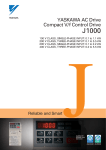
Global Specifications
Supporting global field networks
All models are fully compliant with RS-422/485
(MEMOBUS/Modbus protocol) standards. The networks
are available by using communications option cards.
Now you can connect to hosts and PLC, implement
centralized management of production equipment and
reduce wiring easily.
Digital operator with support for seven languages
The LCD panel digital operator that is included as
standard equipment supports seven languages: Japanese
(katakana), English, German, French, Italian, Spanish,
and Portuguese.
Global standards
Models
Field buses
Certification received: UL/cUL, CE marking, and KC marking
MECHATROLINK-
SI-T
DeviceNet*1
SI-N1
CC-Link
SI-C
PROFIBUS-DP
SI-P1
LONWORKS*2
SI-J
Various power supplies
CANOpen
SI-S1
MEMOBUS
(Modbus)
Standard equipment
(RS-422/485)
Meets a variety of world power supply
Three-phase 200 V series (200 to 240 V)
Three-phase 400 V series (380 to 480 V)
DC power supplies such as common converters are also available.
Global service
Our service networks cover U.S.A., Europe, China, South
East Asia, and other parts of the world, and provide
support for your business abroad.
Varispeed G7 + Communications option cards
*1 DeviceNet is a registered trademark of Open DeviceNet Vendors Association.
*2 LONWORKS is a registered trademark of Echelon Corp.
7
High-level control performance
Outstanding torque characteristics
Accurate torque control
・The new observer (patent pending) improves torque
characteristics (150%/0.3 Hz for open loop vector
control 2) to provide high power for every machine.
With PG, more than 150% high-torque operation is
possible even at zero speed.
・The precision torque limit function allows accurate
control of the output torque, protecting your
machines from sudden load fluctuations.
Motor Speed
1760min-1
Load Torque Reference
Torque (%)
200
180%
100
150%
0
0.3
1.5
3
1s
10
Operation Frequency(Hz)
Torque Reference
High torque from 1/200 speed
Torque Control
(Dynamic auto-tuning, open loop vector control)
[speed control range 1:200 with PG 1:1000]
Proven responsiveness
(Torque limit set at 150%)
High-speed search (patent pending)
・The model tracking control assures fast response
even without PG (doubled in in-house comparison).
・The high-speed search function reduces the recovery time
after momentary power loss (halved in in-house comparison).
・With a PG you can make use of our unique highspeed current vector control, rapidly responses speed
reference changes (speed response 40 Hz/motor
unit). Speed keeps constant even if load fluctuates.
・Recovery is possible regardless of direction of rotation.
960min-1
Input Voltage
(400V/div)
Frequency Reference
(30Hz/div)
Rotation Speed
(12Hz/div)
Output Frequency
(12Hz/div)
Motor Speed
8min-1
450min-1
Output Voltage Reference
(40V/div)
100%
Motor Speed
900min-1
Torque Reference
100%
Motor Current
Torque Reference
27A
8A
50ms
Quick response to
reference changes
(Speed reference step response)
Phase U Output Current
(25A/div)
250ms
Handles sudden load fluctuations
(Speed recovery characteristics
upon load surges)
Simple auto-tuning
・In addition to conventional dynamic auto-tuning, a
new static auto-tuning is available to draw out peak
performance from the motors of the world.
Quick, shockless start
(Continued operation after momentary power loss)
Safety and protection functions
・High-speed, high-precision current control functions support
continuous operation by suppressing overcurrent trips, restart
after momentary power loss, stall prevention and fault retry.
・The PTC thermistor in the motor helps protect it
against overheating.
8
Varispeed G7
User-friendly
Simple operation
・The 5-line LCD display operator makes it simple to check
necessary information. And the copy function simplifies constant
upload and download.
・Easy to setup with the quick program mode.
・Changed constants can be checked at once by the verify mode.
・With the optional extension cable, remote operation is available.
・An LED display operator is available for option.
Easy maintenance and inspection
・Detachable terminals make it easy to exchange units fully wired.
・The one-touch detachable cooling fan life is extended with the
on/off control function.
・The accumulated operation time and the cooling fan operation
time can be recorded and displayed.
・A support tool using a PC is also available. All constants of each
inverter can be managed by a PC.
Varispeed G7
Various I/O interfaces
・In addition to analog command input and analog monitor output,
it also supports pulse train command input and pulse train monitor
output.
S1
Multi-function
Input
+24V 8mA
CN5 (NPN Setting)
SC
+24V
・Offers 10 multi-function inputs and 5 multi-function outputs.
・Input terminal logic can be switched to NPN/PNP type. A +24V
external power supply is also available for selecting the signal
input.
S12
E(G)
Shielded Wire
Connection Terminal
MP
RP Pulse
Train Input
Pulse Train Output
AC
AC
External
Frequency Reference
0V
Easy to make exclusive inverter
・The Varispeed G7 lets you make your exclusive inverters with custom software equipping the special
functions for your specific machines.
・The rich software library, based on our extensive drive expertise*
, helps you upgrade your equipment.
*Crane control, elevator control, energy-saving control (max. motor operation efficiency), PID control, etc.
9
Digital Operator
Digital Operator Functions
Rotating Direction Display
FWD:LED lights at forward run.
R E V :LED lights at reverse run.
Remote Mode
Lights when selecting input mode from the control
circuit terminal.
SEQ:LED lights when selecting run command from
control circuit terminal.
REF:LED lights when selecting frequency reference
from control circuit terminals A1 and A2.
Mode Display
DRIVE :LED lights at Drive
Mode.
QUICK :LED lights at Quick
Programming
Mode.
ADV
:LED lights at
Advanced
Programming
Mode.
VERIFY :LED lights at Verify
Mode.
A. TUNE:LED lights at
Auto-tuning Mode.
Alarm Display
Rdy Display
Can operate when a drive
command is input.
Operation Mode Selection Key
The operation mode is
alternated with REMOTE
(control circuit terminal) and
LOCAL (digital operator)
(When operational command
and frequency reference are
set at control circuit terminal.)
Data Display
Displays data for monitoring,
user constants, and set values.
(1 line×13 characters
and 3 lines×16 characters)
Menu Key
Run Command Keys
Changes the display of operation
and programming mode.
Run command keys for use by
digital operator. Enabled only
in the drive mode.
Escape Key
Returns to the status entered
before [DATA/ENTER] key
was pressed.
JOG :Jog run is enabled
while depressing
this key.
FWD/REV:Selects forward or
reverse run.
Forward and
reverse run is
alternated.
RUN* :Red LED lights by
depressing RUN.
STOP* :Red LED lights by
depressing STOP.
DATA/ENTER Key
Selects mode, group, function
or constant name. Displays
each constant set value while
displaying a constant name.
By pressing this key again,
the set value is written in.
:Increment key
:Decrement key
Selects mode, group, function,
constant name or set value.
* RUN or STOP LED turns ON or OFF, or blinks in accordance with each operation.
Inverter Output Frequency
RUN
STOP
STOP
Frequency Setting
RUN
LED
STOP
LED
○
10
:ON
○
●
○
○
●
○
○
●
○
○
○
:Blinking
●
:OFF
Shift/Reset Key
Selects a digit of a set value to
be changed. The selected
digit blinks.
(Resets operation at faults.)
Easy Operation with Digital Operator
Key Operation
Operator Display
-DRIVE-
Description
U1- 01 =
frequency monitor
display.
0.00Hz
U1-02= 0.00Hz
U1-03= 0.00A
②Operation Condition Setting
z
・Select output
Rdy
Frequency Ref
reference value.
Key Operation
-DRIVE-
U1-02= 0.00Hz
U1-03= 0.00A
u
-DRIVE-
REMOTE(SEQ.REF)LED OFF
FWD LED ON
③Forward Jog Run (6 Hz)
JOG run procedure
(RUNs while depressing
JOG key.)
l
④Frequency Setting
・Change reference value.
f
-DRIVE-
⑤Forward Run
・Forward Run (15 Hz)
Rdy
6.00Hz
-DRIVE-
Rdy
Output Freq
U1- 02 = 15.00Hz
U1-03= 1.45A
U1-04=
2
U1-02= 6.00Hz
U1-03= 1.45A
-DRIVE-
0.00Hz
U1-03= 0.00A
U1-04=
2
Frequency Ref
U1- 01 =
Rdy
Output Freq
U1- 02 =
・Select LOCAL mode.
Rdy
Frequency Ref
U1- 01 = 15.00Hz
REMOTE(SEQ.REF)LED ON
(d1-01=0.00 Hz)
a
Operator Display
Digital Operator
Description
①Power ON
・Displays frequency
RUN LED ON
Rdy
Frequency Ref
U1-01= 000.00Hz
pvu
d
⑥Reverse Run
・Switch to reverse run.
(0.00 60.00Hz)
0.00Hz
-DRIVE-
Rdy
Output Freq
U1- 02 = 15.00Hz
Frequency Ref
U1-03= 1.05A
U1-04=
2
U1-01= 015.00Hz
REV LED ON
-DRIVE-
Rdy
(0.00 60.00Hz)
0.00Hz
・Write-in set value.
f
-DRIVE-
Rdy
Enter Accepted
-DRIVE-
⑦Stop
・Decelerates to a stop.
-DRIVE-
Rdy
0.00Hz
U1-03= 0.00A
U1-04=
2
Frequency Ref
U1-01= 015.00Hz
(cont'd )
Rdy
Output Freq
U1- 02 =
STOP LED ON
(RUN LED blinks
during deceleration.)
(0.00 60.00Hz)
0.00Hz
Note: ■ expresses blinking of numbers
Monitor Display Procedure
【Display at Startup】
-DRIVE-
Rdy
Frequency Ref
U1- 01 = 60.00Hz
U1-02= 0.00Hz
U1-03= 0.00A
【Mode Selection Display】
When frequency reference is 60.00 Hz
A
f
-DRIVE-
Operation
t
**Main Menu**
B
-DRIVE-
①
Rdy
Monitor
**Main Menu**
-QUICK-
z
p
t
t
Rdy
Frequency Ref
U1-01= 060.00Hz
(0.00 60.00Hz)
0.00Hz
u
z
v
z
v
u
-DRIVE-
Rdy
Output Freq
-DRIVE-
Rdy
Fault Trace
U2-02= 0V
U2-03= 60.00Hz
u
v
U1- 02 = 60.00Hz
U1-03=
U1-04=
-DRIVE-
Rdy
1.26A
2
u
v
-DRIVE-
Rdy
Actual Fin Temp
U1- 41 =
**Main Menu**
-A.TUNE-
-DRIVE-
U1-02= 60.00Hz
U1-03= 1.26A
-VERIFY-
Modified Consts
f
U1- 01 = 60.00Hz
Programming
t
Rdy
Frequency Ref
U1-02= 60.00Hz
U1-03= 1.26A
U2 -01=OC
**Main Menu**
-DRIVE-
【Frequency Setting Display】
②
U1- 01 = 60.00Hz
Quick Setting
-ADV-
f
【Monitor Display】
t
34℃
U1-01= 60.00Hz
U1-02= 60.00Hz
Fault History
U3 -01=OC
u
U3-02= 0V
U3-03= 0H
①
②
v
**Main Menu**
Auto-Tuning
u
A
B
v
Note: ■ expresses blinking of numbers
11
Specifications
200 V Class*1
Model CIMR-G7A /
Power Supply Output Characteristics
Max. Applicable
Motor Output*2
20P4 20P7 21P5 22P2 23P7 25P5 27P5 2011 2015
kW 0.4
Inverter Capacity
2018
2022
2030
2037
2045
2055
2075
2090
2110
0.75
1.5
2.2
3.7
5.5
7.5
11
15
18.5
22
30
37
45
55
75
90
110
kVA
1.2
2.3
3.0
4.6
6.9
10
13
19
25
30
37
50
61
70
85
110
140
160
A
3.2
6
8
12
18
27
34
49
66
80
96
130
160
183
224
300
358
415
Rated Current
Max. Voltage
3-phase, 200/208/220/230/240 V (Proportional to input voltage)
Max. Frequency
400Hz by constant setting*3
Rated Input Voltage
and Frequency
Allowable Voltage
Fluctuation
Allowable Frequency
Fluctuation
Three-phase AC power supply: 200/208/220/230/240 V, 50/60 Hz*4
+10 %,−15 %
±5 %
Harmonic Wave DC Reactor
Prevention
12-Pulse Input
Environmental
Conditions
DC power supply: 270 to 340 V*5
Option
Provided
Not available
Available*6
9.8 m/s2 at 10Hz to 20Hz or below, up to
2.0 m/s2 at 20Hz to 55Hz
9.8 m/s2 at 10Hz to 20Hz or below, up to 5.9 m/s2 at 20Hz to 55Hz
Vibration
*1 The main circuit of 200V class inverters uses 2-level control method.
*2 Our standard 4-pole motors are used for max. applicable motor output. Choose the inverter whose rated current is within the motor rated current range.
*3 The setting range for open-loop vector control 2 is 0 to 66Hz (for PROG: 103 , 0 to 132Hz).
*4 When using the inverter of 200 V 30 kW or more with a cooling fan of 3-phase 230 V 50 Hz or 240 V 50/60 Hz power supply, a transformer for the cooling fan is required.
*5 Not compliant with UL or CE standards when using a DC power supply.
*6 Customer must provide a 3-winding transformer when using 12-pulse input.
400 V Class*1
Model CIMR-G7A /
Power Supply Output Characteristics
Max. Applicable
Motor Output*2
Inverter Capacity
40P4 40P7 41P5 42P2 43P7 45P5 47P5 4011 4015 4018 4022 4030 4037 4045 4055 4075 4090 4110 4132 4160 4185 4220 4300
kW 0.4
0.75
1.5
2.2
3.7
5.5
7.5
11
15
18.5
22
30
37
45
kVA
1.4
2.6
3.7
4.7
6.9
11
16
21
26
32
40
50
61
A
1.8
3.4
4.8
6.2
9
15
21
27
34
42
52
65
80
Rated Current
Max. Voltage
Harmonic Wave DC Reactor
Prevention
12-Pulse Input
Environmental
Conditions
Vibration
75
90
110
132
160
185
220
300
74
98
130
150
180
210
250
280
340
460
97
128
165
195
240
270
302
370
450
605
3-phase, 380/400/415/440/460/480 V (Proportional to input voltage)
400Hz by constant setting*3
Max. Frequency
Rated Input Voltage
and Frequency
Allowable Voltage
Fluctuation
Allowable Frequency
Fluctuation
55
Three-phase AC power supply: 380/400/415/440/460/480V, 50/60 Hz
DC power supply: 510 to 680 V*4
+10 %,−15 %
±5 %
Option
Provided
Not available
Available*5
9.8 m/s2 at 10Hz to 20Hz or below, up to 2.0 m/s2
at 20Hz to 55Hz
9.8 m/s2 at 10Hz to 20Hz or below, up to 5.9 m/s2 at 20Hz to 55Hz
*1 The main circuit of 400V class inverters uses 3-level control method.
*2 Our standard 4-pole motors are used for max. applicable motor output. Choose the inverter whose rated current is within the motor rated current range.
*3 The setting range for open-loop vector control 2 is 0 to 66Hz (for PROG: 103 , 0 to 132Hz). The maximum output frequency is 250Hz for 90kW to 110kW and 166Hz for 132kW to 300kW inverters.
*4 Not compliant with UL or CE standards when using a DC power supply.
*5 Customer must provide a 3-winding transformer when using 12-pulse input.
Enclosures
200 V
Class
Model CIMR-G7A / 20P4 20P7 21P5 22P2 23P7 25P5 27P5 2011 2015
Enclosed Type【NEMA1(Type1)】
2018
2022
2030
Available as standard
2045
2055
2075
2090
2110
Not available
Available as standard
Open Chassis Type(IEC IP00) Available by removing the upper and lower cover of enclosed type
400 V
Class
2037
Available for option
Model CIMR-G7A / 40P4 40P7 41P5 42P2 43P7 45P5 47P5 4011 4015 4018 4022 4030 4037 4045 4055 4075 4090 4110 4132 4160 4185 4220 4300
Available for option
Not available
Available as standard
Enclosed Type【NEMA1(Type1)】
Open Chassis Type(IEC IP00) Available by removing the upper and lower cover of enclosed type
Available as standard
Enclosed type【NEMA1(Type1)】: Provides a clean and ventilated environment within the enclosure. Front and rear panels are firmly secured (e.g. front, rear, right, left, top, bottom).
Open chassis type (IEC IP00) : Designed for mounting in a customer's enclosure. Constructed so that openings do not permit direct or inadvertent access to live parts by personnel.
Model Designation
Name Plate Example
CIMR – G7 A 2 0P4 0
Inverter
G7 series
Specifications
A:Japanese standard
specifications
Voltage
2:200 V class
4:400 V class
Protective Enclosure
0:Open chassis type
1:Enclosed type
Max. Applicable Motor Output
0P4:0.4 kW
∼
022: 22 kW
∼
300:300 kW
“P”indicates a decimal
point
〔 〕
12
2 0P4 1 =
Voltage
Max. Applicable
Motor Output
Revision
Enclosure
0:Open chassis type(IEC IP00)
1:Enclosed type【NEMA1
(Type1)
】
Environmental
Conditions
Protective Functions
Control Method
Sine wave PWM
[Vector with PG, open loop vector 1, open loop vector 2*1, V/f, and V/f with PG (switched by parameter)]
Starting Torque
150% at 0.3 Hz (open loop vector control 2), 150% at 0 min-1 (vector control with PG)*2
Speed Control Range
Speed Control Accuracy
Speed Response
Torque Limit
1:200 (open loop vector control 2), 1:1000 (vector control with PG)*2
±0.2%*3 (open loop vector control 2 at 25℃±10℃), ±0.02% (vector control with PG at 25℃±10℃)*2
10 Hz (open loop vector control 2), 40 Hz (vector control with PG)*2
Can be set by parameter: 4 steps available (only when vector control)
Torque Accuracy
Frequency Control Range
Frequency Accuracy
Frequency Setting Resolution
±5 %
Output Frequency Resolution
Overload Capacity*6
Frequency Setting Signal
Accel/Decel Time
0.001 Hz
150% rated output current for 1 minute, 200% rated output current for 0.5 s
0.01 Hz to 400 Hz*4
Digital reference: ±0.01 %, −10 ℃ to +40 ℃ ; Analog reference: ±0.1 %, 25 ℃±10 ℃
Digital reference: 0.01 Hz; Analog reference: 0.03 Hz/60 Hz (11-bit + sign)
Specifications
Control Characteristics
200/400 V Class
−10 to 10 V, 0 to 10 V, 4 to 20 mA, pulse train
0.01 to 6000.0 s (Accel/Decel time setting independently, 4 steps available)
Braking Torque
Approx. 20 % (Approx. 125 % when using braking resistor)*5
Built-in braking transistor provided for inverters of 15 kW or less (200/400 V)
Main Control Functions
Momentary power loss restart, Speed search, Overtorque detection, Torque limit, 17-step speed operation (maximum),
Accel/decel time changeover, S-curve accel/decel, 3-wire sequence, Auto-tuning (dynamic, static), DWELL,
Cooling fan ON/OFF, Slip compensation, Torque compensation, Jump frequency, Frequency upper/lower limit settings,
DC injection braking at start/stop, High slip braking, PID control (with sleep function), Energy-saving control,
MEMOBUS communication (RS-485/422 max. 19.2 kbps), Fault retry, Constant copy, Droop control, Torque control,
Speed/torque control changeover, etc.
Motor Overload Protection
Instantaneous Overcurrent
Fuse Protection
Overload
Overvoltage
Undervoltage
Momentary Power Loss
Electronic thermal overload relay
Motor coasts to stop at approx. 200 % rated output current.
Motor coasts to stop at blown fuse.
150% rated output current for 1 minute, 200% rated output current for 0.5 s
Motor coasts to stop if the main circuit voltage exceeds approx. 410 VDC (approx. 820 VDC for 400 V class).
Motor coasts to stop if the main circuit voltage drops to approx. 190 VDC (approx. 380 VDC for 400 V class) or below.
Immediately stop after 15 ms or longer power loss (at factory setting).
Continuous operation during power loss less than 2 s (standard)*7.
Fin Overheat
Stall Prevention
Thermistor
Ground Fault*8
Power Charge Indication
Location
Humidity
Storage Temperature
Ambient Temperature
Altitude
Provided by electronic circuit (overcurrent level)
Stall prevention during acceleration/deceleration and constant speed operation
Indicates until the main circuit voltage reaches 50 V.
Indoor (Protected from corrosive gasses and dust)
95 %RH (non-condensing)
−20 to 60 ℃ (for short period during shipping)
−10 to 40 ℃ for NEMA1 (type1), −10 to 45 ℃ for open chassis type
1000 m or below
*1
*2
*3
*4
Contact your YASKAWA representatives when using the open-loop vector control 2 for an application with large regenerative power such as hoisting.
Specifications for open loop vector control 1 or 2 and vector control with PG require dynamic auto-tuning.
The speed control accuracy depends on the installation conditions and type of motor used. Contact your Yaskawa representative for details.
The setting range for open-loop vector control 2 is 0.01 to 132 Hz. The maximum output frequency is 250 Hz for 90 kW to 110 kW and 166 Hz for 132 kW to 300 kW
inverters in the 400 V class.
*5 When using a braking resistor or braking resistor unit, set L3-04 = 0 (deceleration stall prevention). If not, motor may not stop at the set time.
*6 Applications with repetitive loads (cranes, elevators, presses, washing machines, etc.) using inverters require derating for the repetitive load [reducing carrier
frequency and current (increasing the frame size of the inverter)]. Contact your Yaskawa representative for details.
*7 Drives with a capacity of smaller than 7.5 kW in the 200 V or 400 V require a separate Momentary Power Loss Recovery Unit (optional).
*8 The ground fault here is one that occurs in the motor wiring during operation. Ground faults may not be detected under the following conditions.
・A ground fault with low resistance which occurs in motor cables or terminals.
・The inverter power supply is turned ON after a ground fault has occurred.
13
Software Functions
Varispeed G7
The Varispeed G7 flexible inverter incorporates a variety of
application features. Select special functions from a multitude
of possibilities to perfectly match your machine
Power
Supply
R/L1
S/L2
T/L3
U/T1
V/T2
W/T3
IM
requirements.
S3
S4
S5
Multi-function
Selection by
Contact Input
S6
Pulse Train
Output
MP
Digital Operator
S7
∼
S12
AM
Pulse Train
Input
FM
RP
A1
A2
A3
AC
Analog Input
Option Card
M1
M2
Input Option
Function
Application
Output Option
Description of Function
Ref. Page
Energy Saving
Control
General
PID Control
Automatic
Pumps, air
conditionings, etc. process control
Speed Search
Operation
Inertia load drives Synchronize with Starts the inverter at the specified frequency, automatically detects the
such as blowers,
the coasting
synchronization point, and performs at the operation frequency.
etc.
motor
No speed detector is required.
40
DC Injection
Braking at Start
When the direction of the free running motor is not fixed, the speed search
Blowers, pumps,
Starting the free
operation function is difficult to use. The motor can be automatically
etc. which have
running motor
stopped by DC injection braking, and be restarted by the inverter.
wind-mill effects
40
Commercial Power
Source/Inverter
Switchover Operation
Blowers, pumps,
mixers, extruders,
etc.
Automatic
switching between Switching of commercial power source to inverter or vice versa is done
commercial power without stopping the motor.
source and inverter
Multi-step Speed
Operation
Transporting
equipment
Schedule operation
under fixed speed
and positioning
Accel/Decel Time
Changeover
Operation
Automatic control
panels, transporting
equipment, etc.
Inverter Overheat
Prediction
14
Target Market
Multi-function
Signal Output
P1
P2
PC
P3
C3
P4
C4
R+
R−
S+
S−
IG
MEMOBUS
Communication
Analog Output
AC
Most efficient
Supplies voltage to motor to always be most effective according to load and rotating speed.
automatic operation (Automatic temperature compensation function provided)
The accel/decel
time changeover
with an external
signal
Air conditioners, Preventive
etc.
maintenance
Processes PID operation in the inverter and the result is used as frequency reference.
If controls pressure, air/water amounts.
55
53
40, 58
Multi-step operation (up to 17-step) can be set by setting the contact
combinations, so the connection with PLC becomes very easy.
When combined with jog speed can also allow simple positioning.
36
The accel/decel times are switched by an external contact signal.
Necessary for switching operation of two machines with different functions
by a single inverter.
37
When the ambient temperature of the inverter rises to within 10 ℃ of the maximum
allowable temperature, warning is given. (Thermoswitch is required as an option.)
47
Operation can be accomplished using
Simple
a spring-loaded push-button switch.
configuration
of control circuit
STOP
RUN
S1
S2
S5
SC
RUN
STOP
FWD/REV
3-wire Sequence
General
Operating Site
Selection
General
Easy operation
Operation and settings can be selected while the inverter is online.
(digital operator/external instruction, signal input/output).
47
Frequency Hold
Operation
General
Easy operation
Temporarily holds frequencies during acceleration or deceleration.
41
UP/DOWN Command
General
Easy operation
Sets speed by ON/OFF from a distance.
47
Fault Trip Retry
Operation
When the inverter trips, it begins to coast, is immediately diagnosed by
Air conditioners, Improvement of
computer, resets automatically, and returns to the original operation speed.
etc.
operation reliability
Up to 10 retries can be selected.
Quick Stop without
Braking Resistor
(DC injection
braking stop)
High-speed
routers,etc.
DC injection
braking stop of
induction motor
DC injection braking is performed at top speed. The duty is 5 % or less.
Can generate 50 % to 70 % of the braking torque.
47
41
46
Target Market
Torque Limit
Blowers, pumps,
extruders, etc.
Torque Control*
Droop Control*
Upper/Lower Frequency
Limit Operation
Prohibit Setting of
Specific Frequency
(Frequency Jump
Control)
Carrier Frequency
Setting
Application
・Protection of machine The inverter can be switched to coasting or motor speed reducing mode
・Improvement of
as soon as it reaches a certain preset torque level. For pump or blower,
continuous operation
the operation frequency can be automatically reduced to the load balancing
reliability
point, according to the overload condition, and prevent overload tripping.
・Torque limit
Winders, extruders, ・Tension constant control Adjusts motor torque externally. Appropriate for controlling winder tension
and the result of torque booster.
・Torque booster
boosters
Separately-driven
conveyors, multiArbitrarily set motor speed regulation. High insulation characteristics share
motor drive, feeders, Dividing loads
multi-motor loads.
transporting
equipment.
The upper and lower limits of the motor speed, reference signal bias and
Pumps, blowers Motor speed limit
gain can be set independently without peripheral operation units.
Prevent mechanical The motor simply passes through the preset speed, but continuous running
cannot be done at this speed. This function is used to avoid the mechanical
General machines vibration in the
resonance point of the equipment.
equipment
General machines
Automatic Continuous
Air conditioners
Operation When the
Speed Reference is Lost
Load Speed
General
Display
Lower noise, eliminate resonance
Improving reliability
of continuous
operation
Monitor function
enhancement
Zero-frequency
interlock
Run Signal
General
Zero-speed Signal
Machine tools
Frequency (Speed)
Agreed Signal
Reference speed
reach interlock
・Protection of
Machine tools,
machine
blowers, cutters, ・Improvement of
extruders, etc.
operation reliability
Overtorque
Signal
Description of Function
Zero-frequency
interlock
The carrier frequency can be set to reduce the acoustic noise from the
motor and machine system.
When the frequency reference signal is lost, operation is automatically
continued at the pre-programmed speed. (If the host computer fails.)
This function is important for air conditioning systems in intelligent buildings.
Can indicate motor speed (min-1), machine speed under load (min-1), line
speed (m/min), etc.
“Closed” during operation. “Open” during coasting to a stop.
Can be used as interlock contact point during stop.
“Closed” when output frequency is under min. frequency.
Can be used as tool exchange signal.
Ref. Page
49
―
―
38
38
44
40
35
48
48
The contact closes when inverter output frequency reaches the set value.
Can be used as an interlock for lathes, etc.
48
“Closed” when overtorque setting operation is accomplished. Can be used as a
torque limiter.
42
General
System protection “Closed” only when tripped by low voltage. Can be used as a countermeasure
power loss detection relay.
for undervoltage
48
General
Reference speed “
Closed” when the speed agrees at arbitrary frequency reference.
agreed interlock
48
General
Gear change
interlock etc.
48
Machine tools
Low Voltage
Signal
Free Unintentional
Speed Agreement Signal
Output Frequency
Detection 1
Output Frequency
Detection 2
General
Base Block Signal
General
Gear change
“Closed” at or below the arbitrary output frequency.
interlock etc.
Operation interlock,
Always “closed” when the inverter output is OFF.
etc.
General
preventive
maintenance
“Closed” when a built-in braking resistor overheats, or a braking transistor
error is detected.
48
General
Operation
stability
“Closed” when the frequency reference suddenly drops to 10 % or below
of the set value.
48
General
Easy operation
Functions as supplementary frequency reference. Also used for fine control
of input reference, output voltage adjustment, external control of accel/decel
time, and fine adjustment of overtorque detection level.
―
General
Monitor function
Either a frequency meter, ammeter, voltmeter, or wattmeter can be used.
enhancement
General
Easy operation
Enables external operation with high resolution instructions (AI-14U, AI-14B).
Also enables normal and reverse operation using positive or negative voltage signals (AI-14B).
―
General
Easy operation
Enables operation with 8-bit or 16-bit digital signals. Easily connects to NC or PC
(DI-08, DI-16H2).
―
Braking Resistor
Protection
Frequency Reference
Sudden Change
Detection
Multi-function
Analog Input
Signal
Multi-function
Analog Output Signal
Analog Input
(option)
Digital Input
(option)
Analog Output
(option)
Digital Output
(option)
Pulse Train Input
General
General
General
Pulse Train
Output
General
PG Speed Control
(option)
General
“Closed” at or over an arbitrary output frequency.
Monitor function Monitors output frequency, motor current, output voltage, and DC voltage.
enhancement
(AO-08, AO-12)
Monitor function
Indicates errors through discrete output (DO-08).
enhancement
PID target and PID feedback values are input with pulse train when PID
Easy operation
control as well as frequency reference function.
Monitor function Six items including PID target and PID feedback values can be monitored
enhancement
as well as frequency reference and output frequency.
Enhancement of Installing PG controller card (PG-A2, PG-B2, PG-D2, PG-X2)
considerably enhances speed control accuracy.
speed control
Software Functions
Function
48
48
44
44
―
38
45
51
* Torque control and droop control functions are applicable for vector control with PG and open loop vector control 2.
15
Connection Diagram and Terminal Functions
*10
Varispeed G7
Example of 200 V 18.5 kW (CIMR-G7A2018)
2MCCB
Wiring sequence should shut
off power to the drive when a
fault output is triggered.
ELCB or MCCB
A separate transformer is
required when running
from a 400 V power supply
to step the voltage down
to 200 V.
Fuse
*2
G3
Thermal Relay
Trip Contact of
Braking Resistor
MC
Forward
Run/Stop
2
4
Fault Reset
2
TRX
PG-B2
Option
MC
MA
Fault
Contact
Multi-function
Input
Factory
Setting
V
Ground
(100 Ω or less)
*5
H
B
G
5
A
6
F
TA3
D
TA2
Multi-Step
Speed Setting 2
S6
JOG Reference
S7
External Base
Block Reference
S8
MP
Multi-Step
Speed Setting 3
S9
AC
Multi-Step
Speed Setting 4
S10
Accel/Decel Time
Setting 1
S11
Emergency Stop
(NO Contact)
S12
Pulse Monitor Output
30mA max.
A Pulse
3
4
30m or less
wiring
B Pulse
Pulse Train Output
0 to 32 kHz(2.2 kΩ)
Output Frequency at
Factory Setting
*9
Ammeter Adjusting Potentiometer
20 kΩ
*7
AM
Multi-function Analog Output 2
*1
−
+24 V 8 mA
AM
−10∼+10 V 2 mA
+
Output Current at Factory
Setting 0 to +10V
Frequency Meter Adjusting Potentiometer
20 kΩ
*7
FM
*6
E(G)
*1
Pulse Train Input
RP
Multi-function Analog Output 1
P
Shielded Wire
Connection Terminal
MA
Master Freq. Pulse Train
− FM +
−10∼+10 V 2 mA
Output Frequency at Factory
Setting 0 to 10V
P
MC
+V
Freq. Setting Power Supply
A1
Master Freq. Ref.
A2
Master Freq. Ref.
+15 V 20 mA
0 to 10 V(20 kΩ)
0V
*9
-V
MEMOBUS
Communication
RS-485/422
*1
Fault Contact Output *8
250 VAC 1 A or less
30 VDC 1 A or less
MC
Multi-function Contact Output *8
M2
250 VAC 1 A or less
30 VDC 1 A or less
Run Signal at
Factory Setting
P1
Aux. Freq. Ref
at Factory Setting
Open Collector Output 1
Zero Speed Signal
at Factory Setting
P2
*3 (−15 V 20 mA)
PC
Terminal
Resistance
R+
R−
MA
M1
Multi-function Analog Input
0 to 10 V(20 kΩ)
A3
AC
*1
MB
4 to 20 mA(250 Ω)*7
[0 to 10 V(20 kΩ)input available]
P
*1 indicates shield wire and
E(G)
*3
0∼+10 V
0∼+10 V
+24 V
0 to 32 kHz(3 kΩ)
Hi level:3.5 to 13.2 V input
Adjusting Resistor
2 kΩ for Frequency
Setting
4∼20 mA
PG
Twister-pair
Shied Wire
*1
1
*9
2
1
C
2
AC
2 kΩ
IM
W
1
S5
SC
Master
Frequency
Reference
IM
FW
3
4
CN5
(NPN Setting)
Frequency
Setter
3
Cooling Fan
U
TA1
2
TRX
S1
V/T2
S4
Multi-Step
Speed Setting 1
SA
R1
T1
S3
External Fault
SA
Thermal Relay
Trip Contact of Motor Cooling Fan
3
FU
FV
W/T3
S2
Thermal switch contact
for Braking Unit
Motor
B
Braking
Resistor
(Option)
S1
Reverse
Run/Stop
THRX
1
*6
MC
SA
F0
U/T1
Varispeed G7
T/L3
ON
2
P
F
R/L1
S/L2
MC MB 2MCCB THRX OFF
1
G0
F
G1
Thermal Relay
Trip Contact
4
Level
Detector
R1
S1
T1
MC
3
G
*4
R
3-phase
Power Supply
200 to 240 V S
50/60 Hz
T
1
Thermoswitch Contact
DC Reactor
(Option)
P3
S+
C3
S−
P4
IG
C4
Open Collector Output 2
Frequency Agreement
Signal at Factory Setting
Open Collector Output 3
Ready to Operate at
Factory Setting
Multi-function
Open Collector
Output
48 VDC 50 mA
or less
Open Collector Output 4
Minor Fault at
Factory Setting
P indicates twisted-pair shield wire.
*2 Terminal symbols: ◎ shows main circuit; ○ shows control circuit.
*3 The output current capacity of the +V and −V terminals are 20 mA. Do not short-circuit between the +V, −V, and AC terminals. Doing so may result in a malfunction or a breakdown of the Inverter.
*4 When using self-cooled motors, wiring for cooling fan motor is not required.
*5 PG circuit wiring (i.e., wiring to the PG-B2 Board) is not required for control without a PG.
*6 Connection when sequence input signals (S1 to S12) are no-voltage contacts or sequence connections (0 V common/sink mode) by NPN transistor (factory setting).
When sequence connections by PNP transistor (+24 V common/source mode) or preparing a external +24 V power supply, see Typical Connection Diagrams (p64).
*7 Multi-function analog output is only for use on meters (frequency, current, voltage and watt), and not available for the feedback control system.
*8 The minimum permissible load of a multi-function contact output and an error contact output is 10 mA. Use a multi-function open-collector output for a load less than 10 mA.
*9 Do not ground nor connect the AC terminal on the control circuit to the unit. Doing so may result in a malfunction or a breakdown of the Inverter.
*10 Set constant L8-01 to 1 when using a breaking resistor (model ERF). When using a Braking Resistor Unit, a shutoff sequence for the power supply must be made using a thermal relay trip.
Note: For applications where the power supply for the inverter's main circuit is turned off while the power supply for the inverter's control circuit is on, a power-supply unit
for each circuit and a specially designed inverter are available. Contact your Yaskawa representative for more information.
Control Circuit and Communication Circuit Terminal Arrangement
Screw terminal
Screw type terminal
E(G) FM
SC
16
S1
S2
AC
A1
S3
AM
A2
S4
P1
A3
S5
P2
+V
S6
PC
AC
S7
SC
−V
S8
MP
RP
S9
P3
R+
S10
C3
R−
S11
Screw type terminal
P4
S+
S12
C4
S−
IG
MA
M1
MB
MC
M2
E(G)
Terminal Functions
Main Circuit
Voltage
400 V
200 V
Model CIMR-G7A _
20P4 to 2015
2018,2022
2030 to 2110
40P4 to 4015
4018 to 4045
4055 to 4300
0.4 to 15 kW
18.5 to 22 kW
30 to 110 kW
0.4 to 15 kW
18.5 to 45 kW
55 to 300 kW
Max Applicable Motor Output
Main circuit input power supply
Main circuit input power supply
Main circuit input power supply
Main circuit input power supply
R/L1, S/L2, T/L3
―
―
R-R1, S-S1 and T-T1 have been wired before shipment (See P66).
R-R1, S-S1 and T-T1 have been wired before shipment (See P66).
R1/L11, S1/L21, T1/L31
Inverter output
Inverter output
U/T1, V/T2, W/T3
Braking resistor unit
Braking resistor unit
―
―
B1, B2
・DC reactor
・DC reactor
F
・DC power supply
・DC power supply
(G 1 ― G 2)
(G 1 ― G 2)
G1
(G 1 ― F)*1
(G 1 ― F)*1
・DC power supply*1
(G 1 ― F)
G2
・Braking unit
(G 3 ― F)
・DC power supply*1
(G 1 ― F)
・Braking unit
(G 3 ― F)
Control Circuit (200 V/400 V Class)
Classification
Sequence
Input
Analog Input
Terminal
S1
S2
S3
S4
S5
S6
S7
S8
S9
S10
S11
S12
SC
+V
−V
A1
A2
A3
AC
E
(G)
P1
P2
Photo-coupler
Output
Description
Signal Level
Forward run at “closed”, stop at “open”
Reverse run at “closed”, stop at “open”
Factory setting: external fault at “closed”
Factory setting: fault reset at “closed”
Factory setting: multi-step speed setting 1 is valid at “closed”
Factory setting: multi-step speed setting 2 is valid at “closed”
Photo-coupler insulation
Factory setting: JOG run at “closed”
Input 24 VDC 8 mA
Factory setting: external baseblock at “closed”
Factory setting: multi-speed setting 3 is valid at “closed”
Factory setting: multi-speed setting 4 is valid at “closed”
Factory setting: accel/decel time setting 1 is valid at “closed”
Factory setting: emergency stop (NO contact) is valid at “closed”
―
For analog reference +15 V power supply
+15 V (Allowable current 20 mA max.)
For analog reference −15 V power supply
−15 V (Allowable current 20 mA max.)
−10 to +10 V/−100 to +100%, 0 to +10 V/100 % −10 to +10 V, 0 to +10 V (Input impedance 20 k )
4 to 20 mA/100 %, −10 to +10 V/−100 to +100%, 0 to +10 V/100 %
4 to 20 mA (Input impedance 250 Ω)
Multi-function analog input
Factory setting: added to the terminal A1 (H3-09=0)
−10 to +10V/−100 to +100%, 0 to +10V/100%
0 to +10 V (Input impedance 20 kΩ)
Master speed frequency ref.
Factory setting: preset frequency reference
―
0V
Analog common
Connection to shield wire and option ground wire
―
―
Factory setting: zero speed signal
Multi-function PHC output 1
“Closed” at or below zero speed level (b2-01)
Factory setting: frequency agreement
Multi-function PHC output 2
“Closed” within ±2 Hz of setting frequency
48 Vdc or less, 2 to 50 mA
―
Photo-coupler output common
Photocoupler output*
Factory setting: ready to operate (READY)
Multi-function PHC output 3
Signal Function
Forward run-stop signal
Reverse run-stop signal
Multi-function input selection 1
Multi-function input selection 2
Multi-function input selection 3
Multi-function input selection 4
Multi-function input selection 5
Multi-function input selection 6
Multi-function input selection 7
Multi-function input selection 8
Multi-function input selection 9
Multi-function input selection 10
Sequence control input common
+15 V Power supply output
−15 V Power supply output
Master speed frequency ref.
PC
P3
C3
P4
Factory setting: minor fault
Multi-function PHC output 4
C4
“
Fault at closed” between terminals MA and MC
Fault output (NO contact)
MA
Dry contact, contact capacity
Fault at “open” between terminals MB and MC
Fault output (NC contact)
MB
250 VAC 1 A or less
Relay Output
―
Relay contact output common
MC
30 VDC 1 A or less
Factory setting: Run signal
M1
Multi-function contact output (NO contact)
Running at “closed” between terminals M1 and M2
M2
Factory setting: output frequency 0 to 10 V/100 % freq.
Multi-function analog monitor 1
FM
Analog Monitor
0 to ±10 VDC ±5 %
Factory setting: current monitor 5 V/inverter rated current
Multi-function analog monitor 2
AM
Output
2 mA or less
―
Analog common
AC
0 to 32 kHz(3 kΩ)
Factory setting: frequency reference input (H6-01=0)
Multi-function pulse input
RP
Pulse I/O
Factory setting: output frequency (H6-06=2)
0 to 32 kHz(2.2 kΩ)
Multi-function pulse monitor
MP
Flywheel diode
*: Connect a flywheel diode as shown below when driving a reactive load such as a relay coil.
Diode must be rated higher than the circuit voltage.
External power
48 V max.
Coil
(50 mA max.)
Communication Circuit Terminal (200/400 V Class)
Classification
RS-485/422
Transmission
Terminal
R+
R−
S+
S−
IG
Signal Function
MEMOBUS communication input
MEMOBUS communication output
Shielded wire for communication
Description
When using two RS-485 wires, short-circuit
between R+ and S+, R− and S−.
―
Signal Level
Differential input
PHC isolation
Differential output
PHC isolation
―
17
Connection Diagram and Terminal Functions
―
―
G3
s/b2
Cooling fan power supply
―
―
*2
r/b1
Cooling fan power supply
―
s 200/b2 200
―
*3
s 400/b2 400
Ground terminal(100 Ω or less)
Ground terminal(10 Ω or less)
J
*1 G 1 − F DC power input does not conform to UL/c-UL listed standard.
*2 Cooling fan power supply r/l1−s/l2: 200 to 220 VAC 50 Hz, 200 to 230 VAC 60 Hz
(A transformer is required for 230 V 50 Hz or 240 V 50/60 Hz power supply.)
*3 Cooling fan power supply r/l1−s 200/l2 200: 200 to 220 VAC 50 Hz, 200 to 230 VAC 60 Hz, r/l1−s 400/l2 400: 380 to 480 VAC 50/60 Hz
Dimensions
Open Chassis Type(IEC IP00)
H1
3
W1
T1
3
W
D
Drawing 1
H1
H
(5)
W
(5)
(5)
D
T1
D1
W3
W1
W
D
Drawing 3
Voltage
Max. Applicable
Motor Output
kW
0.4
0.75
1.5
2.2
3.7
5.5
7.5
11
15
200 V
18.5
Class
(3-phase) 22
30
37
45
55
75
90
110
0.4
0.75
1.5
2.2
3.7
5.5
7.5
11
15
18.5
22
400 V
30
Class
37
(3-phase)
45
55
75
90
110
132
160
185
220
300
Inverter
CIMR-G7A _
20P4
20P7
21P5
22P2
23P7
25P5
27P5
2011
2015
2018
2022
2030
2037
2045
2055
2075
2090
2110
40P4
40P7
41P5
42P2
43P7
45P5
47P5
4011
4015
4018
4022
4030
4037
4045
4055
4075
4090
4110
4132*
4160*
4185
4220
4300
DWG
T1
D1
H2
H2
H2*
H1
6-d
W2
4-d
H*
D
Drawing 2
W1
W1
T1
D1
H2
H
H1
H2
W
D1
H
4-d
4-d
H
W1
Drawing 4
W
H
D
W1
Dimensions in mm
H1
W2
W3
140
280
157
126
140
280
177
200
300
240
250
275
375
600
450
Approx. Mass Cooling
kg
Method
H2
D1
T1
d
266
7
39
5
M5
3
126
266
7
59
5
M5
4
197
186
285
8
65.5
2.3
M6
6
7
350
207
216
400
450
258
258
298
328
195
220
725
500
575
1
2
335
7.5
78
2.3
M6
11
385
435
7.5
7.5
2.3
2.3
M6
M6
250
575
12.5
100
100
100
130
348
325
700
12.5
130
3.2
850
358
370
820
15
130
4.5
21
24
57
63
86
87
108
885
378
445
855
15
140
4.5
140
280
157
126
266
7
39
5
M5
3.5
140
280
177
126
266
7
59
5
M5
4.5
200
300
197
186
285
8
65.5
2.3
M6
7
240
350
207
216
335
7.5
78
2.3
M6
10
275
450
258
220
435
7.5
100
2.3
M6
26
325
550
283
260
535
7.5
105
2.3
M6
37
3
−
−
3.2
M10
M12
Self
cooled
Fan
cooled
150
Self
cooled
1
2
3
4
−
−
450
725
348
325
700
12.5
130
3.2
M10
500
850
358
370
820
15
130
4.5
M12
575
916*
378
445
855
45.8*
140
4.5
M12
710
1305
15
126
4.5
M12
916
1475
415
540
240
270
1270
730
365
365
1440
*: Dotted lines show dimensions for models of the CIMR-G7A 4132 and 4160.
18
90
91
109
127
165
175
263
280
415
Fan
cooled
Enclosed Type【NEMA 1 (Type 1)】
3
H2
W1
W
D
Drawing 1
W1
H
3
D
Drawing 2
Dimensions
H0
H
H1
4-d
H3
(5)
W
10 max.
H2
(5)
T1
D1
4
H1
H
H0
4
H1
H2
W
T1
D1
H0
4-d
4-d
H3
W1
T1
D1
(5)
D
Drawing 3
Voltage
Max. Applicable
Motor Output
kW
0.4
0.75
1.5
2.2
3.7
5.5
7.5
11
200 V
15
Class
(3-phase) 18.5
22
30
37
45
55
75
0.4
0.75
1.5
2.2
3.7
5.5
7.5
11
400 V
15
Class
18.5
(3-phase)
22
30
37
45
55
75
90
110
132
160
Inverter
CIMR-G7A _
20P4
20P7
21P5
22P2
23P7
25P5
27P5
2011
2015
2018
2022
2030
2037
2045
2055
2075
40P4
40P7
41P5
42P2
43P7
45P5
47P5
4011
4015
4018
4022
4030
4037
4045
4055
4075
4090
4110
4132
4160
DWG
W
H
140
280
D
W1
Dimensions in mm
H0
H1
H2
126
280
H3
266
7
―
177
200
2
254
279
350
380
535
615
380
809
240
3
300
197
186
300
285
207
216
350
335
258
195
220
400
450
385
435
298
328
250
600
575
8
0
7.5
0
30
135
165
453
1027
348
325
725
700
504
1243
358
370
850
820
140
300
197
302
15
280
266
7
186
300
285
Approx. Mass Cooling
kg
Method
3
4
65.5
6
7
78
2.3
M6
100
3.2
M10
4.5
M12
130
393
―
8
11
24
27
62
68
94
95
114
3.5
5
Self
cooled
Fan
cooled
Self
cooled
M5
59
4.5
65.5
7
―
2
240
279
329
350
535
635
207
258
283
216
220
260
350
450
550
335
435
78
7.5
100
10
2.3
M6
29
85
535
39
105
165
715
3
M5
209
177
200
5
39
126
280
d
59
12.5
157
1
T1
39
157
1
D1
453
1027
348
325
725
700
12.5
302
504
1243
358
370
850
820
15
393
579
1324
378
445
916
855
45.8
408
3.2
M10
4.5
M12
130
140
Fan
cooled
40
98
99
127
137
175
185
19
Mounting to a Gasketed Cabinet (Internal Sink)
The standard enclosure (with the heatsink mounted internally)
can be easily changed to an externally mounted heatsink
,
arrangement, but the enclosure s mounting face must be
gasketed.
Mounting the External Heatsink Ventilation Space
Cooling Design for Fully-Closed
Enclosure Panel
When using open chassis type inverters of 200/400 V
18.5 kW or more, secure spaces for eyebolts and wiring
of the main circuit.
Remove the upper and lower covers for
inverters of 200/400 V 15 kW or less .
Upper Cover
Internal Heatsink
Upper Cover
55 ℃
A mm or more*
Upper Part Air
Temperature
−10 to 55 ℃
B mm or more*
Air
Heatsink
Heatsink
Open Chassis
Type Inverter
Lower Cover
Inverter Inlet
Temperature
−10 to 45 ℃
45 ℃
30 mm or more
50 mm or more
Ambient
Temperature 40 ℃
Lower Cover
Cover MTG Screw
30 mm
or more
Side Spaces
120 mm or more
Air
Top and Bottom Spaces
*Refer to the following specifications for securing spaces.
When using the inverters of 90 kW to 110 kW in the 200V class or 132 kW to 220 kW
in the 400V class.
A : 120 B : 120
When using the inverter of 300 kW in the 400V class
A : 300 B : 300
All other inverters
A : 50 B : 120
With a fan on the ceiling of the enclosed cabinet for exhausting
A : 50 B : 120
Inverter Heat Loss
200 V Class
Model CIMR-G7A _
Inverter Capacity
1.2 2.3 3.0 4.6 6.9
10
13
19
25
30
37
A
3.2
6
8
12
27
34
49
66
80
96 130 160 183 224 300 358 415
Fin
W
21
43
58
83 122 187 263 357 473 599 679 878 1080 1291 1474 2009 1963 2389
Inside Unit
W
36
42
47
53
Total Heat Loss
W
57
85 105 136 186 274 375 493 647 839 936 1240 1514 1801 2081 2832 2888 3583
Rated Current
Heat Loss W
20P4 20P7 21P5 22P2 23P7 25P5 27P5 2011 2015 2018 2022 2030 2037 2045 2055 2075 2090 2110
kVA
Fin Cooling
18
64
50
61
70
85 110 140 160
87 112 136 174 242 257 362 434 510 607 823 925 1194
Self cooled
Fan cooled
400 V Class
Model CIMR-G7A _
Inverter Capacity
1.4 2.6 3.7 4.7 6.9
11
16
21
26
32
40
50
61
74
A
1.8 3.4 4.8 6.2
9
15
21
27
34
42
52
65
80
97 128 165 195 240 270 302 370 450 605
Fin
W
10
21
33
41
76 132 198 246 311 354 516 633 737 929 1239 1554 1928 2299 2612 3614 4436 5329 6749
Inside Unit
W
39
44
46
49
64
Total Heat Loss
W
49
65
79
90 140 211 304 362 446 528 726 879 1022 1269 1727 2150 2690 3227 3717 5115 6430 7534 9690
Heat Loss W
Rated Current
Fin Cooling
20
40P4 40P7 41P5 42P2 43P7 45P5 47P5 4011 4015 4018 4022 4030 4037 4045 4055 4075 4090 4110 4132 4160 4185 4220 4300
kVA
Self cooled
98 130 150 180 210 230 280 340 460
79 106 116 135 174 210 246 285 340 488 596 762 928 1105 1501 1994 2205 2941
Fan cooled
Attachments
■ Heatsink External Mounting Attachment
The Varispeed G7 inverters under the 200/400 V class 15 kW or less need this attachment for mounting the heatsink externally.
This attachment expands the outer dimensions of the width and height of the inverter. (Attachment is not required for inverters
Mounting Panel
(in mm)
Wall
Model
CIMR-G7A _
D1
W
H
W1
H1
EZZ08676A
155
302
126
290 122.6
20P4
20P7
21P5
22P2
23P7
25P5
27P5
2011
2015
40P4
40P7
41P5
42P2
43P7
45P5
47P5
4011
4015
H1
H
W1
W
Attachment
Order Code
D2
D3 or more
b
a
30
(H2)
B
(W3)
(W3)
A
(H3)
(H2)
a
(W2)
(W2)
15
Drawing 1
4-d Tap
a
H1
(H)
(H2)
a
b
W1
W
(H2) (H3)
a
W1
(W)
Drawing 4
6-d Tap
(W3)
a
W1
W
Drawing 2
4-d Tap
a
(W3)
A
(W3)
(W2)
(W2)
(W3)
A
(W3)
W1
(W2)
(W2)
a
a
W1
W
Drawing 3
(H3) (59)
(W)
Drawing 5
15
H1
H
(H2)
B
a
H1
(H)
a
B
(W2)
(19) (H3)
(W2)
(H3) (H2)
(H2)
A
20
H1
H
B
(W3)
40
57.4
60
180
316 136.1 63.4
70
EZZ08676C
250
392
216
372 133.6 76.4
85
37.4
40
EZZ08676A
155
302
126
290 122.6
57.4
60
EZZ08676B
210
330
180
316 136.1 63.4
70
EZZ08676C
250
392
216
372 133.6 76.4
85
(Heatsink)
(in mm)
H1
H
(W3)
(W2)
A
37.4
330
Model
Drawing W
CIMR-G7A _
B
(W3)
(W2)
D3
210
20
6-d Tap
(H2)
a
(H3)
2-5 Dia. Holes
D2
EZZ08676B
Panel Cut for External Mounting of Cooling Fin
4-d Tap
D1
Dimensions
of 18.5 kW or more.)
20P4
20P7
21P5
22P2
23P7
25P5
27P5
2011
2015
2018
2022
2030
2037
2045
2055
2075
2090
2110
40P4
40P7
41P5
42P2
43P7
45P5
47P5
4011
4015
4018
4022
4030
4037
4045
4055
4075
4090
4110
4132
4160
4185
4220
4300
H
W1 (W2)
(W3) H1 (H2)
(H3) A
155 302 126
6
B
d
8.5 290 9.5
6
138 271 M5
6.5 316
7
197 298
8.5 372 9.5
10
233 353 M6
385
435
8
7.5
244 369
269 419
575
15
1
210 330 180
9
8.5
250 392 216
250 400 195
24.5
275 450 220
3
375 600 250
2
54.5
8
450 725 325
359 545
12.5
700 13.5
500 850 370
57
8
820
575 885 445
55
10
855
155 302 126
6
M10
434 673
484 782
19
15
8.5 290 9.5
6
138 271 M5
6.5 316
7
197 298
10
233 353
555 817
M12
1
210 330 180
9
8.5
250 392 216
8.5 372 9.5
275 450 220
3
435
24.5
269 419
8
325 550 260
M6
7.5
535
309 519
2
450 725 325 54.5
500 850 370
8
57
700 13.5 12.5 434 673 M10
820
19
484 782
15
3
575 925 445
55
10
895
*
555 817 M12
4
710 1305 540 76.5 8.5 1270 21.5 *
693 1227
5
916 1475 730 72.5 20.5 1440 21.5 *
875 1397
* The sizes are different between the top and the bottom. Refer to Drawings 3 to 5.
21
Constants List
How to read this list ・Constants not described in this list are not displayed in the digital operator.
・Setting constants vary in accordance with password setting (A1-04).
・A, Q and × represent access level and capability.
A:ADVANCED (when the advanced program mode is selected)
Q:QUICK (when the quick program mode and the advanced mode are selected)
×:Cannot be accessed.
Function
No.
Name
Setting Range
Minimum
Setting
Unit
Control Mode
Factory Online
Ref.
V/f
V/f
Open
Open
Flux
Setting Changing without with Loop Vector
Loop Page
PG
PG
Vector1
A1-00
A1-01
Initialize A1-02
Mode
A1-03
A1-04
A1-05
User-set A2-01
Constants to A2-32
Language selection for digital operator display
Constant access level
Control method selection
Initialize
Password
Password setting
0 to 6
1
1
○
A
A
A
A
0 to 2
1
2
○
A
A
A
A
A
0 to 4
1
2
×
Q
Q
Q
Q
Q
0 to 3330
1
0
×
A
A
A
A
A
0 to 9999
1
0
×
A
A
A
A
A
0 to 9999
1
0
×
A
A
A
A
A
User setting constants
b1-01 to o3-02
―
―
×
A
A
A
A
A
b1-01
b1-02
b1-03
b1-04
Operation
b1-05
Mode
Selections b1-06
b1-07
b1-08
b1-10
b2-01
b2-02
DC
Injection b2-03
Braking b2-04
b2-08
b3-01
b3-02
b3-03
b3-05
Reference selection
Operation method selection
Stopping method selection
Prohibition of reverse operation
Operation selection for setting E1-09 or less
Read sequence input twice
Operation selection after switching to remote mode
Run command selection in programming modes
Mode selection for zero speed
Zero speed level (DC injection braking starting frequency)
DC injection braking current
DC injection braking time at start
DC injection braking time at stop
Magnetic flux compensation volume
Speed search selection
Speed search operating current (current detection)
Speed search deceleration time (current detection)
Speed search wait time
Speed search detection compensation
gain (speed calculation)
0 to 4
1
1
×
Q
Q
Q
Q
Q
0 to 3
1
1
×
Q
Q
Q
Q
Q
Speed
Search
b3-10#
*1
31
31
35
1
0
×
Q
Q
Q
Q
Q
46
1
0
×
A
A
A
A
A
36
0 to 3
1
0
×
×
×
×
A
×
0,1
1
1
×
A
A
A
A
A
0,1
1
0
×
A
A
A
A
A
0,1,2#
1
0
×
A
A
A
A
A
A
1
0
×
×
×
×
×
0.1 Hz
0.5 Hz
×
A
A
A
A
A
1%
50 %
×
A
A
A
×
×
0.00 to 10.00
0.01 s
0.00 s
×
A
A
A
A
A
0.00 to 10.00
0,1
0.0 to 10.0
0 to 100
0.01 s
0.50 s
×
A
A
A
A
A
0 to 1000
0 to 3
1%
1
0%
2*2
×
×
×
A
×
A
×
A
A
×
×
A
0 to 200
1%
100 %*2
×
A
×
A
×
A
0.1 to 10.0
0.1 s
2.0 s
×
A
×
A
×
×
0.0 to 20.0
0.1 s
0.2 s
×
A
A
A
A
A
1.00 to 1.20
0.01
1.10
×
A
×
A
×
A
0.1 %
1.0 %
×
×
×
×
×
A
1
1%
1
150%
×
A
A
A
×
A
A
×
×
A
×
0.01 s
0.10 s
×
A
×
A
×
A
1
0
×
A
×
A
×
A
0.0 to 300.0
0.1 s
0.0 s
×
A
A
A
A
A
0.0 to 300.0
0.1 s
0.0 s
×
A
A
A
A
A
Proportional gain of the speed
0.1 to 2.0
estimator during speed search
b3-14#
Rotation direction search selection 0,1
Speed search retrial current level
Speed search retrial detection time
Number of speed search retrials
Timer function ON-delay time
Timer function OFF-delay time
PID control mode selection
Proportional gain (P)
Integral (I) time
Integral (I) limit
0 to 200
0.00 to 1.00
0 to 10
0 to 4
1
0
×
A
A
A
A
A
0.01
1.00
○
A
A
A
A
A
0.0 to 360.0
0.1 s
1.0 s
○
A
A
A
A
A
0.0 to 100.0
0.1 %
100.0 %
○
A
A
A
A
A
Derivative (D) time
0.00 to 10.00
0.01 s
0.00 s
○
A
A
A
A
A
PID limit
PID offset adjustment
PID primary delay time constant
PID output characteristics selection
PID output gain
PID reverse output selection
Selection of PID feedback command loss detection
PID feedback command loss detection level
PID feedback command loss detection time
PID sleep function operation level
PID sleep operation delay time
Accel/decel time for PID reference
0.0 to 100.0
0.1 %
100.0 %
○
A
A
A
A
A
−100.0 to +100.0
0.1 %
0.0 %
○
A
A
A
A
A
0.00 to 10.00
0.01 s
0.00 s
○
A
A
A
A
A
1
0
×
A
A
A
A
A
0.1
1.0
×
A
A
A
A
A
0,1
1
0
×
A
A
A
A
A
0 to 2
1
0
×
A
A
A
A
A
0 to 100
1%
0%
×
A
A
A
A
A
0.0 to 25.5
0.1 s
1.0 s
×
A
A
A
A
A
0.0 to 400.0
0.1 Hz
0.0 Hz
×
A
A
A
A
A
0.0 to 25.5
0.1 s
0.0 s
×
A
A
A
A
A
0.0 to 25.5
0.1 s
0.0 s
×
A
A
A
A
A
0,1
0.0 to 25.0
―
40
46
―
―
A
0.00 to 25.00
#:The constants are available only for version PRG: 1039 or later.
The settings and control modes marked with # are also available for version PRG: 1039 or later.
*1 The setting range is 0 or 1 for flux vector control and open-loop vector control 2.
*2 The factory setting will change when the control method (A1-02) is changed. (Open-loop vector 1 factory settings are given.)
22
A
0,1
0 to 3
b3-13#
b3-17#
b3-18#
b3-19#
b4-01
Timer
Function b4-02
b5-01
b5-02
b5-03
b5-04
b5-05
b5-06
b5-07
b5-08
PID
b5-09
Control
b5-10
b5-11
b5-12
b5-13
b5-14
b5-15
b5-16
b5-17
Vector2
40
48
53
―
No.
b6-01
Name
Dwell frequency at start
DROOP
Control
Energy
Saving
Zero
Servo
Acceleration
/Deceleration
S-curve
Acceleration
/Deceleration
Motor
Slip
Compensation
Torque
Compensation
Speed
Control
(ASR)
Minimum
Setting
Unit
Factory Online
Setting Changing
Control Mode
V/f
V/f
Open Flux Open
without with Loop Vector Loop
PG
PG Vector1
Vector2
0.0 to 400.0
0.1 Hz
0.0 Hz
×
A
A
A
A
A
0.0 to 10.0
0.1 s
0.0 s
×
A
A
A
A
A
0.0 to 400.0
0.1 Hz
0.0 Hz
×
A
A
A
A
A
Dwell time at stop
Droop control gain
Droop control delay time
0.0 to 10.0
0.1 s
0.0 s
×
A
A
A
A
A
0.0 to 100.0
0.1
0.0 %
○
×
×
×
A
A
0.03 to 2.00
0.01 s
0.05 s
○
×
×
×
A
A
Energy-saving mode selection
Energy-saving gain
Energy-saving filter time constant
Energy-saving coefficient
Power detection filter time constant
Search operation voltage limiter
Zero-servo gain
Zero-servo completion width
Acceleration time 1
Deceleration time 1
Acceleration time 2
Deceleration time 2
Acceleration time 3
Deceleration time 3
Acceleration time 4
Deceleration time 4
Emergency stop time
Accel/decel time setting unit
Accel/decel time switching frequency
S-curve characteristic time at acceleration start
S-curve characteristic time at acceleration end
S-curve characteristic time at deceleration start
S-curve characteristic time at deceleration end
Slip compensation gain
Slip compensation primary delay time
Slip compensation limit
Slip compensation selection during regeneration
Output voltage control limit selection
Torque compensation gain
Torque compensation primary delay time constant
Forward starting torque
Reverse starting torque
Starting torque time constant
ASR proportional (P) gain 1
ASR integral (I) time 1
ASR proportional (P) gain 2
ASR integral (I) time 2
ASR limit
ASR primary delay time
ASR switching frequency
ASR integral (I) limit
ASR primary delay time 2
0,1
b6-02 Dwell time at start
DWELL
Functions b6-03 Dwell frequency at stop
b6-04
b7-01
b7-02
b8-01
b8-02
b8-03
b8-04
b8-05
b8-06
b9-01
b9-02
C1-01
C1-02
C1-03
C1-04
C1-05
C1-06
C1-07
C1-08
C1-09
C1-10
C1-11
C2-01
C2-02
C2-03
C2-04
C3-01
C3-02
C3-03
C3-04
C3-05
C4-01
C4-02
C4-03
C4-04
C4-05
C5-01
C5-02
C5-03
C5-04
C5-05
C5-06
C5-07
C5-08
C5-10
Setting Range
1
0
×
A
A
A
A
A
0.1
0.7*1
○
×
×
A
A
A
0.00 to 10.00
0.01 s
0.50 s*2
○
×
×
A
A
A
0.00 to 655.00
0.01
*1 *3
×
A
A
×
×
×
0 to 2000
1 ms
20 ms
×
A
A
×
×
×
0 to 100
1%
0%
×
A
A
×
×
×
0 to 100
1
5
×
×
×
×
A
×
0 to 16383
1
10
×
×
×
×
A
×
○
Q
Q
Q
Q
Q
○
Q
Q
Q
Q
Q
○
A
A
A
A
A
○
A
A
A
A
A
×
A
A
A
A
A
×
A
A
A
A
A
×
A
A
A
A
A
×
A
A
A
A
A
×
A
A
A
A
A
0.0 to 10.0
0.0 to 6000.0*4
0,1
0.1 s
10.0s
1
1
×
A
A
A
A
A
0.0 to 400.0
0.1 Hz
0.0 Hz
×
A
A
A
A
A
0.00 to 2.50
0.01 s
0.20 s
×
A
A
A
A
A
0.00 to 2.50
0.01 s
0.20 s
×
A
A
A
A
A
0.00 to 2.50
0.01 s
0.20 s
×
A
A
A
A
A
0.00 to 2.50
A
0.01 s
0.00 s
×
A
A
A
A
0.0 to 2.5
0.1
1.0*5
○
A
×
A
A
A
0 to 10000
1 ms
200 ms*5
×
A
×
A
×
×
0 to 250
1%
200 %
×
A
×
A
×
×
1
0
×
A
×
A
×
×
0,1
1
0
×
×
×
A
A
A
0.00 to 2.50
0.01
1.00
○
A
A
A
×
×
0 to 10000
1 ms
20 ms*5
×
A
A
A
×
×
0.0 to 200.0
0.1 %
0.0 %
×
×
×
A
×
×
−200.0 to 0.0
0.1 %
0.0 %
×
×
×
A
×
×
0 to 200
1 ms
10 ms
×
×
×
A
×
×
0,1
0.00 to 300.00*7
0.01
20.00*6
○
×
A
×
A
A
0.000 to 10.000
0.001 s
0.500 s*6
○
×
A
×
A
A
0.00 to 300.00*7
0.01
20.00*6
○
×
A
×
A
A
0.000 to 10.000
0.001 s
0.500 s*6
○
×
A
×
A
A
0.0 to 20.0
0.1 %
5.0 %
×
×
A
×
×
×
0.000 to 0.500
0.001 s
0.004 s*6
×
×
×
×
A
A
0.0 to 400.0
0.1 Hz
0.0 Hz
×
×
×
×
A
A
0 to 400
1%
400 %
×
×
×
×
A
A
0.000 to 0.500
0.001
0.010 s
×
×
×
×
×
A
Ref.
Page
―
―
55
―
34
37
Constants List
Function
37
51
―
49
―
51
*1 The factory setting is 1.0 when using flux vector control.
*2 When inverter capacity is 55 kW min., the factory settings are 0.05 s for flux vector control and 2.00 s for open-loop vector control 2.
The factory setting will change when the control method (A1-02) is changed. (Open-loop vector 1 factory settings are given.)
*3 The same capacity as the inverter will be set by initializing the constants.
*4 The setting range for acceleration/deceleration times will depends on the setting for C1-10. When C1-10 is set to 0, the setting range for acceleration/deceleration
times becomes 0.00 to 600.00 s.
*5 The factory setting will change when the control method (A1-02) is changed. (Open-loop vector 1 factory settings are given.)
*6 The factory setting will change when the control method (A1-02) is changed. (Flux vector factory settings are given.)
*7 The setting range is 1.00 to 300.0 for flux vector control and open-loop vector control 2.
23
Function
No.
Name
C6-02
C6-03
C6-04
Carrier
Frequency C6-05
Carrier frequency selection
Carrier frequency upper limit
Carrier frequency lower limit
Carrier frequency proportional gain
Carrier
frequency selection
C6-11
for open-loop vector control 2
Preset
Reference
Reference
Limits
Jump
Frequency
Reference Frequency Hold
Torque
Control
Field
Weakening
d1-01
d1-02
d1-03
d1-04
d1-05
d1-06
d1-07
d1-08
d1-09
d1-10
d1-11
d1-12
d1-13
d1-14
d1-15
d1-16
d1-17
d2-01
d2-02
d2-03
d3-01
d3-02
d3-03
d3-04
d4-01
d4-02
d5-01
d5-02
d5-03
d5-04
d5-05
d5-06
d5-07
d6-01
d6-02
d6-03
d6-05
d6-06
Frequency reference 1
Frequency reference 2
Frequency reference 3
Frequency reference 4
Frequency reference 5
Frequency reference 6
Frequency reference 7
Frequency reference 8
Frequency reference 9
Frequency reference 10
Frequency reference 11
Frequency reference 12
Frequency reference 13
Frequency reference 14
Frequency reference 15
Frequency reference 16
Jog frequency reference
Setting Range
1 to F*1
15.0*3*4
0.4 to 15.0*3*4
2.0 to
00 to 99*4
Minimum
Setting
Unit
Factory Online
Setting Changing
Control Mode
V/f
V/f
Open Flux Open
without with Loop Vector Loop
PG
PG Vector1
Vector2
×
Q
Q
Q
Q
×*5
0.1 kHz
15.0
kHz*2
×
A
A
A
A
×
0.1 kHz
15.0 kHz*2
×
A
A
×
×
×
1
0
×
A
A
×
×
×
1
6*2
*5
1 to 4
0 to 400.00*6
0.01 Hz*7
1*9
0.00 Hz
*5
44
―
*5
×
×
×
×
×
Q
○
Q
Q
Q
Q
Q
○
Q
Q
Q
Q
Q
○
Q
Q
Q
Q
Q
○
Q
Q
Q
Q
Q
○
A
A
A
A
A
○
A
A
A
A
A
○
A
A
A
A
A
○
A
A
A
A
A
○
A
A
A
A
A
○
A
A
A
A
A
○
A
A
A
A
A
○
A
A
A
A
A
○
A
A
A
A
A
○
A
A
A
A
A
○
A
A
A
A
A
○
A
A
A
A
A
36
0.01 Hz*7
6.00 Hz
○
Q
Q
Q
Q
Q
Frequency reference upper limit 0.0 to 110.0
0.1 %
100.0 %
×
A
A
A
A
A
Frequency reference lower limit
0.0 to 110.0
0.1 %
0.0 %
×
A
A
A
A
A
Master-speed reference lower limit 0.0 to 110.0
0.1 %
0.0 %
×
A
A
A
A
A
Jump frequency 1
0.1 Hz
0.0 Hz
×
A
A
A
A
A
0.1 Hz
0.0 Hz
×
A
A
A
A
A
0.1 Hz
0.0 Hz
×
A
A
A
A
A
0.1 Hz
1.0 Hz
×
A
A
A
A
A
1
0
×
A
A
A
A
A
41
1%
10 %
×
A
A
A
A
A
―
Jump frequency 2
0 to 400.00*6
1
*5
Ref.
Page
0.0 to 400.0
Jump frequency 3
Jump frequency width
0.0 to 20.0
Frequency reference hold function selection 0,1
+− Speed limits
0 to 100
Torque control selection
Torque reference delay time
Speed limit selection
Speed limit
Speed limit bias
Speed/torque control switching timer
0,1
1
0
×
×
×
×
A
A
1 ms
0 ms*8
×
×
×
×
A
A
1
1
×
×
×
×
A
A
−120 to +120
1%
0%
×
×
×
×
A
A
0 to 120
1%
10 %
×
×
×
×
A
A
0 to 1000
1 ms
0 ms
×
×
×
×
A
A
1
1
×
×
×
×
×
A
1%
80 %
×
A
A
×
×
×
0.1 Hz
0 to 1000
1,2
Rotation direction limit operation selection 0,1
Field weakening level
0 to 100
Field frequency
0.0 to 400.0
0.0 Hz
×
A
A
×
×
×
Field forcing function selection 0,1
AφR time constant
0.00 to 10.00
1
0
×
×
×
×,A#
A
A
0.01
1.00
×
×
×
×
×
A
Field forcing limit
1%
400 %
×
×
×
A
A
A
100 to 400
38
38
―
―
*1 The setting range depends on the capacity of the inverter (o2-04). If the carrier frequency is set higher than the factory setting for inverters with outputs of 5.5 kW
or more, the inverter rated current will need to be reduced.
*2 The factory setting depends on the capacity of the inverter (o2-04). The value for a 200 V class inverter of 0.4 kW is given.
*3 The setting range depends on the capacity of the inverter (o2-04). The maximum output frequency depends on the setting for the carrier frequency.
*4 This constant can be monitored or set only when F is set for C6-02.
*5 Displayed in Quick Programming mode when motor 2 is set for a multi-function input.
*6 The setting range is 0 to 66.0 for open-loop vector control 2.
*7 The unit is set in o1-03.
*8 The factory setting will change when the control method (A1-02) is changed. (Flux vector factory settings are given.)
*9 This factory setting is for version PRG: 1040 or later. For version 1039 or earlier, the factory setting depends on the capacity of the inverter (o2-04).
24
No.
E1-01
E1-03
E1-04
E1-05
E1-06
E1-07
V/f
Pattern E1-08
E1-09
E1-10
E1-11
E1-12
E1-13
E2-01
E2-02
E2-03
E2-04
E2-05
E2-06
Motor
Setup
E2-07
E2-08
E2-09
E2-10
E2-11
E2-12
E3-01
E3-02
E3-03
Motor 2 E3-04
V/f
E3-05
Pattern
E3-06
E3-07
E3-08
E4-01
E4-02
E4-03
Motor 2
E4-04
Setup
E4-05
E4-06
E4-07
F1-01
F1-02
F1-03
PG
Option F1-04
Setup
F1-05
F1-06
F1-07
Name
Setting Range
Minimum
Setting
Unit
Control Mode
Factory Online
Ref.
V/f
V/f
Open Flux Open
Setting Changing without with Loop Vector
Loop Page
PG
PG
Vector1
1V
200 V*1
×
Q
Q
Q
Q
Q
1
F
×
Q
Q
×
×
×
0.1 Hz
60.0 Hz*3
×
Q
Q
Q
Q
Q
0.1 V
200.0 V*1*3
×
Q
Q
Q
Q
Q
0.0 to 400.0*2
0.1 Hz
60.0 Hz*3
×
Q
Q
Q
Q
Q
0.0 to 400.0*2
0.1 Hz
3.0 Hz*3
×
A
A
A
×
×
Input voltage setting
155 to 255*1
V/f pattern selection
0 to F
Max. output frequency
40.0 to 400.0*2
Max. voltage
0.0 to 255.0*1
Base frequency
Mid. output frequency
*1
*1*3
Vector2
Mid. output frequency voltage
0.0 to 255.0
0.1 V
11.0 V
×
A
A
A
×
×
Min. output frequency
0.0 to 400.0*2
0.1 Hz
0.5 Hz*3
×
Q
Q
Q
A
Q
Min. output frequency voltage
0.0 to 255.0*1
0.1 V
2.0 V*1*3
×
A
A
A
×
×
Mid. output frequency 2
0.0 to 400.0*2
0.1 Hz
0.0 Hz*4
×
A
A
A
A
A
Mid. output frequency voltage 2
0.0 to 255.0*1
0.1 V
0.0 V*4
×
A
A
A
A
A
Base voltage
0.0 to 255.0*1
0.1 V
0.0 V*5
×
A
A
Q
Q
Q
Motor rated current
Motor rated slip
Motor no-load current
Number of motor poles
Motor line-to-line resistance
Motor leak inductance
Motor iron saturation coefficient 1
Motor iron saturation coefficient 2
Motor mechanical loss
Motor iron loss for torque compensation
Motor rated output
0.32 to 6.40*6
0.01 A
1.90 A*7
×
Q
Q
Q
Q
Q
0.00 to 20.00
0.01 Hz
2.90 Hz*7
×
A
A
A
A
A
0.00 to 1.89*8
0.01 A
1.20 A*7
×
A
A
A
A
A
2
4 pole
×
×
Q
×
Q
Q
2 to 48
0.001 Ω
9.842 Ω*7
×
A
A
A
A
A
0.0 to 40.0
0.1 %
18.2 %*7
×
×
×
A
A
A
0.00 to 0.50
0.01
0.50
×
×
×
A
A
A
0.50 to 0.75
0.01
0.75
×
×
×
A
A
A
0.0
×
×
×
×,A#
A
A
1W
14 W*7
×
A
A
×
×
×
0.01 kW
0.4 kW*9
×
Q
Q
Q
Q
Q
0.01
1.30
×
×
×
A
A
A
1
2
×
A
A
A
A
A
0.1 Hz
60.0 Hz
×
A
A
A
A
A
0.0 to 255.0*4
0.1 V
200.0 V*3
×
A
A
A
A
A
Motor 2 max. voltage frequency (FA) 0.0 to 400.0*2
0.1 Hz
60.0 Hz
×
A
A
A
A
A
Motor 2 mid. output frequency (FB) 0.0 to 400.0*2
0.1 Hz
3.0 Hz*3
×
A
A
A
F
F
Motor 2 mid, output frequency voltage (VC) 0.0 to 255.0*4
0.1 V
11.0 V*3*4
×
A
A
A
F
F
Motor 2 min. output frequency (FMIN) 0.0 to 400.0*2
0.1 Hz
0.5 Hz*3
×
A
A
A
A
A
Motor 2 min. output frequency voltage (VMIN) 0.0 to 255.0*4
0.1 V
2.0 V*3*4
0.000 to 65.000
0.0 to 10.0
0 to 65535
0.00 to 650.00
Motor iron saturation coefficient 3 1.30 to 1.60*10
Motor 2 control method selection 0 to 4
Motor 2 max. output frequency (FMAX) 40.0 to 400.0*2*5
Motor 2 max. voltage (VMAX)
×
A
A
A
F
F
Motor 2 rated current
0.32 to 6.40
0.01 A
1.90 A*7
×
A
A
A
A
A
Motor 2 rated slip
0.00 to 20.00
0.01 Hz
2.90 Hz*7
×
A
A
A
A
A
Motor 2 no-load current
0.00 to 1.89*8
0.01 A
1.20 A*7
×
A
A
A
A
A
Motor 2 number of poles
2 to 48
2
4 pole
×
×
A
×
A
A
Motor 2 line-to-line resistance
0.000 to 65.000
0.001 Ω
9.842 Ω*7
×
A
A
A
A
A
Motor 2 leak inductance
0.0 to 40.0
0.1 %
18.2 %*7
×
×
×
A
A
A
Motor 2 rated capacity
0.40 to 650.00
0.01 kW
0.40 kW*7
×
A
A
A
A
A
PG constant
0 to 60000
1
600
×
×
Q
×
Q
×
Operation selection at PG open circuit (PGO) 0 to 3
1
1
×
×
A
×
A
×
Operation selection at overspeed 0 to 3
1
1
×
×
A
×
A
A
Operation selection at deviation
0 to 3
1
3
×
×
A
×
A
A
PG rotation
0,1
1
0
×
×
A
×
A
×
PG division rate (PG pulse monitor) 1 to 132
1
1
×
×
A
×
A
×
Integral value during accel/decel enable/disable 0,1
1
0
×
×
A
×
×
×
*6
31
33
34
32
―
Constants List
Function
―
―
―
*1 There are values for a 200 V class inverter. Values for a 400 V class inverter are double.
*2 The setting range for open-loop vector 2 control is 0 to 66.0 (0 to 132.0 for PRG: 103 □). The maximum output frequency of the 400V-class inverter is restricted by the setting of carrier frequency
and its capacity. The maximum output frequency is 250Hz for 90kW to 110kW and 166Hz for 132kW to 300kW inverters in the 400V class.
*3 The factory setting will change when the control method (A1-02) is changed. (Open-loop vector 1 factory settings are given.)
*4 E1-11 and E1-12 are disregarded when set to 0.0.
*5 When E1-13 (Base voltage) is set to 0.0, the output voltage is controlled with E1-05 (Maximum voltage) = E1-13.
When autotuning is performed, E1-05 and E1-13 are automatically set to the same value.
,
*6 The setting range is 10% to 200% of the inverter s rated output current. The value for a 200 V class inverter of 0.4 kW is given.
*7 The factory setting depends on the capacity of the inverter (o2-04). The value for a 200 V class inverter of 0.4 kW is given.
*8 The setting range depends on the capacity of the inverter (o2-04). The value for a 200 V class inverter of 0.4 kW is given.
*9 The same capacity as the inverter will be set by initializing the constants.
*10 This constant is automatically set during autotuning.
25
Function
No.
PG
Option
Setup
F1-08
F1-09
F1-10
F1-11
F1-12
F1-13
F1-14
Analog
Reference
Card
Digital
Reference
Card
Name
Setting Range
Control Mode
Factory Online
Ref.
V/f
V/f
Open
Open
Flux
Setting Changing without with Loop Vector
Loop Page
PG
PG
Vector1
Overspeed detection level
0 to 120
1%
115 %
×
×
A
×
A
A
Overspeed detection delay time
0.0 to 2.0
0.1 s
0.0 s*1
×
×
A
×
A
A
Excessive speed deviation detection level 0 to 50
1%
10%
×
×
A
×
A
A
Excessive speed deviation detection delay time 0.0 to 10.0
0.1 s
0.5 s
×
×
A
×
A
A
1
0
×
×
A
×
×
×
Number of PG gear teeth 1
0 to 1000
0
×
×
A
×
×
×
2.0 s
×
×
A
×
A
×
0,1
1
0
×
A
A
A
A
A
―
Digital input option
0 to 7
1
0
×
A
A
A
A
A
―
Channel 1 monitor selection
1 to 50
Channel 1 gain
0.00 to 2.50
Channel 2 monitor selection
1 to 50
Channel 2 gain
F2-01
Bi-polar or uni-polar input
selection
F3-01
1
2
×
A
A
A
A
A
0.01
1.00
○
A
A
A
A
A
1
3
×
A
A
A
A
A
0.00 to 2.50
0.01
0.5
○
A
A
A
A
A
Channel 1 output monitor bias
−10.0 to 10.0
0.1
0.0
○
A
A
A
A
A
Channel 2 output monitor bias
−10.0 to 10.0
0.1
0.0
○
A
A
A
A
A
Analog output signal level for channel 1 0,1
Analog output signal level for channel 2 0,1
1
0
×
A
A
A
A
A
1
0
×
A
A
A
A
A
Channel 1 output selection
0 to 37
1
0
×
A
A
A
A
A
Channel 2 output selection
0 to 37
1
1
×
A
A
A
A
A
Channel 3 output selection
0 to 37
1
2
×
A
A
A
A
A
Channel 4 output selection
0 to 37
1
4
×
A
A
A
A
A
Channel 5 output selection
0 to 37
1
6
×
A
A
A
A
A
Channel 6 output selection
0 to 37
1
37
×
A
A
A
A
A
Channel 7 output selection
0 to 37
1
0F
×
A
A
A
A
A
Channel 8 output selection
0 to 37
1
0F
×
A
A
A
A
A
DO-08 output mode selection
0 to 2
1
0
×
A
A
A
A
A
Operation selection after communications error 0 to 3
1
1
×
A
A
A
A
A
F6-02
Input level of external fault from
Communications Option Card
0,1
1
0
×
A
A
A
A
A
F6-03
Stopping method for external fault from
Communications Option Card
0 to 3
1
1
×
A
A
A
A
A
1
0
×
A
A
A
A
A
1
1
×
×
×
×
A
A
1
0
×
×
×
×
A
A
Operation selection after SI-T WDT error 0 to 3
Number of SI-T BUS error detection 2 to 10
1
1
×
A
A
A
A
A
1
2
×
A
A
A
A
A
Terminal S3 function selection
0 to 79
1
24
×
A
A
A
A
A
Terminal S4 function selection
0 to 79
1
14
×
A
A
A
A
A
Terminal S5 function selection
0 to 79
1
*2
3(0)
×
A
A
A
A
A
Terminal S6 function selection
0 to 79
1
*2
4(3)
×
A
A
A
A
A
Terminal S7 function selection
0 to 79
1
*2
6(4)
×
A
A
A
A
A
Terminal S8 function selection
0 to 79
1
*2
8(6)
×
A
A
A
A
A
Terminal S9 function selection
0 to 79
1
5
×
A
A
A
A
A
Terminal S10 function selection
0 to 79
1
32
×
A
A
A
A
A
Terminal S11 function selection
0 to 79
1
7
×
A
A
A
A
A
Terminal S12 function selection
0 to 79
1
15
×
A
A
A
A
A
Terminal M l-M2 function selection (contact) 0 to 37
Terminal P1 function selection (open collector) 0 to 37
1
0
×
A
A
A
A
A
1
1
×
A
A
A
A
A
Terminal P2 function selection (open collector) 0 to 37
Terminal P3 function selection (open collector) 0 to 37
1
2
×
A
A
A
A
A
1
6
×
A
A
A
A
A
Terminal P4 function selection (open collector) 0 to 37
1
10
×
A
A
A
A
A
F6-06
F6-08
F6-09
H1-01
H1-02
H1-03
H1-04
Multifunction H1-05
Contact H1-06
Inputs
H1-07
H1-08
H1-09
H1-10
H2-01
MultiH2-02
function
H2-03
Contact
Outputs H2-04
H2-05
―
1
0.0 to 10.0
Trace sampling from Communications
Communi0 to 60000
F6-04
Option Card
cations
Option
Torque reference/torque limit selection
0,1
F6-05
Card
from Communications Option Card
Torque reference/torque limit selection
0,1
from Communications Option Card
*1 The factory setting will change when the control method (A1-02) is changed. (Flux vector factory settings are given.)
*2 The values in parentheses indicate initial values when initialized in 3-wire sequence.
26
Vector2
0.1 s
Number of PG gear teeth 2
PG open-circuit detection time
F4-01
F4-02
F4-03
Analog F4-04
Monitor
F4-05
Card
F4-06
F4-07
F4-08
F5-01
F5-02
F5-03
Digital F5-04
Output F5-05
Card
F5-06
F5-07
F5-08
F5-09
F6-01
Minimum
Setting
Unit
―
―
―
36
47
48
48
Multifunction
Analog
Inputs
Multifunction
Analog
Outputs
MEMOBUS
Communications
Pulse
Train I/O
No.
Name
Setting Range
Minimum
Setting
Unit
Control Mode
Factory Online
Ref.
V/f
V/f
Open
Open
Flux
Setting Changing without with Loop Vector
Loop Page
PG
PG
Vector1
H3-01
H3-02
H3-03
H3-04
H3-05
H3-06
H3-07
H3-08
H3-09
H3-10
H3-11
H3-12
H4-01
H4-02
H4-03
H4-04
H4-05
H4-06
H4-07
H4-08
H5-01
H5-02
H5-03
H5-04
H5-05
H5-06
H5-07
H5-10#
H6-01
H6-02
H6-03
H6-04
H6-05
Signal level selection (terminal A1) 0,1
Gain (terminal A1)
0.0 to 1000.0
1
0
×
A
A
A
A
A
0.1 %
100.0 %
○
A
A
A
A
A
Bias (terminal A1)
0.1 %
0.0 %
○
A
A
A
A
A
1
0
×
A
A
A
A
A
1
2
×
A
A
A
A
A
H6-06
Pulse train monitor selection
H6-07
L1-01
L1-02
Motor
L1-03
Overload
L1-04
L1-05
L2-01
L2-02
L2-03
Power Loss L2-04
Ridethrough L2-05
L2-06
L2-07
L2-08
−100.0 to +100.0
Signal level selection (terminal A3) 0,1
Multi-function analog input (terminal A3) 0 to 1F
Vector2
Gain (terminal A3)
0.0 to 1000.0
0.1 %
100.0 %
○
A
A
A
A
A
Bias (terminal A3)
−100.0 to +100.0
0.1 %
0.0 %
○
A
A
A
A
A
1
2
×
A
A
A
A
A
1
0
×
A
A
A
A
A
Multi-function analog input terminal A2 signal level selection 0 to 2
Multi-function analog input terminal A2 function selection 0 to 1F
Gain (terminal A2)
0.0 to 1000.0
0.1 %
100.0 %
○
A
A
A
A
A
Bias (terminal A2)
−100.0 to +100.0
0.1 %
0.0 %
○
A
A
A
A
A
Analog input filter time constant
0.00 to 2.00
0.01 s
0.03 s
×
A
A
A
A
A
1
2
×
A
A
A
A
A
Monitor selection (terminal FM) 1 to 45,1 to 50#
Gain (terminal FM)*1
0.00 to 2.50
Bias (terminal FM)*1
−10.0 to +10.0
Monitor selection (terminal AM) 1 to 45,1 to 50#
Gain (terminal AM)*1
0.00 to 2.50
Bias (terminal AM)*1
−10.0 to +10.0
Analog output 1 signal level selection 0,1
Analog output 2 signal level selection 0,1
0.01
1.00
○
Q
Q
Q
Q
Q
0.0 %
○
A
A
A
A
A
1
3
×
A
A
A
A
A
44
0.01
0.50
○
Q
Q
Q
Q
Q
45
0.1 %
0.0 %
○
A
A
A
A
A
1
0
×
A
A
A
A
A
1
0
×
A
A
A
A
A
0 to 20*2
1
1F
×
A
A
A
A
A
Communication speed selection
0 to 4
1
3
×
A
A
A
A
A
Communication parity selection
0 to 2
1
0
×
A
A
A
A
A
Stopping method after communication error 0 to 3
1
3
×
A
A
A
A
A
Communication error detection selection 0,1
1
1
×
A
A
A
A
A
Send wait time
5 to 65
1 ms
5 ms
×
A
A
A
A
A
RTS control ON/OFF
0,1
1
1
×
A
A
A
A
A
Unit Selection for MEMOBUS Register 0025H 0,1
1
0
×
A
A
A
A
A
Pulse train input function selection 0 to 2
1
0
×
A
A
A
A
A
Pulse train input scaling
1000 to 32000
1 Hz
1440 Hz
○
A
A
A
A
A
Pulse train input gain
0.0 to 1000.0
0.1 %
100.0 %
○
A
A
A
A
A
Pulse train input bias
−100.0 to +100.0
0.1 %
0.0 %
○
A
A
A
A
A
Pulse train input filter time
0.00 to 2.00
1,2,5,20,24,
36 only
0.01 s
0.10 s
○
A
A
A
A
A
1
2
○
A
A
A
A
A
Pulse train monitor scaling
0 to 32000
1 Hz
1440 Hz
○
A
A
A
A
A
Motor protection selection
0 to 3
Motor protection time constant
0.1 to 5.0
1
1
×
Q
Q
Q
Q
Q
0.1 min
1.0 min
×
A
A
A
A
A
Alarm operation selection during motor overheating 0 to 3
1
3
×
A
A
A
A
A
Motor overheating operation selection 0 to 2
1
1
×
A
A
A
A
A
0.01 s
0.20 s
×
A
A
A
A
A
1
0
×
A
A
A
A
A
Momentary power loss ridethru time 0 to 25.5
0.1 s
0.1 s*3
×
A
A
A
A
A
Min. baseblock time
0.1 to 5.0
0.1 s
0.2 s*3
×
A
A
A
A
A
Voltage recovery time
0.0 to 5.0
0.1 s
0.3 s*3
×
A
A
A
A
A
Undervoltage detection level
150 to 210*4
1V
190 V*4
×
A
A
A
A
A
KEB deceleration time
0.0 to 200.0
0.1 s
0.0 s
×
A
A
A
A
A
Momentary recovery time
0.0 to 25.5
0.1 s
0.0 s*5
×
A
A
A
A
A
1
100 %
×
A
A
A
A
A
Momentary power loss detection 0 to 2
Frequency reduction gain at KEB start 0 to 300
―
0.1 %
Station address
Motor temperature input filter time constant 0.00 to 10.00
39
Constants List
Function
54
―
38
―
45
52
―
40
―
#:The constants are available only for version PRG: 1039 or later. The settings and control modes marked with # are also available for version PRG: 1039 or later.
*1 While the inverter is stopped, the output voltage for the output channels 1 and 2 can be adjusted in the quick programming mode, the advanced programming
mode, or the verify mode. The output channel 1 can be adjusted while the data setting display for H4-02 or H4-03 is monitored. The output channel 2 can be
adjusted while the data setting display for H4-05 or H4-06 is monitored. The following voltage will be output. 100% monitor output × output gain + output bias
*2 Set H5-01 to 0 to disable inverter response to MEMOBUS communications.
*3 The factory setting depends on the capacity of the inverter (o2-04). The value for a 200 V class inverter of 0.4 kW is given.
*4 There are values for a 200 V class inverter. Values for a 400 V class inverter are double.
*5 If the setting is 0, the axis will accelerate to the specified speed over the specified acceleration time (C1-01 to C1-08).
27
Function
No.
L3-01
L3-02
L3-03
L3-04
Stall
Prevention L3-05
L3-06
L3-11
L3-12
L4-01
L4-02
Reference
L4-03
Detection
L4-04
L4-05
L5-01
Fault
Restart L5-02
L6-01
L6-02
L6-03
Torque
Detection L6-04
L6-05
L6-06
L7-01
L7-02
Torque L7-03
Limits
L7-04
L7-06
L7-07
L8-01
L8-02
L8-03
L8-05
L8-07
L8-09
L8-10
Hardware
L8-11
Protection
L8-12
L8-15
L8-18
L8-32
L8-38#
L8-39#
L8-41#
Hunting
N1-01
Prevention
N1-02
Function
Name
Setting Range
PG
PG
Vector1
1
×
A
A
A
×
×
Stall prevention level during accel 0 to 200
1%
150 %
×
A
A
A
×
×
Stall prevention limit during accel 0 to 100
1%
50 %
×
A
A
A
×
×
Stall prevention selection during decel 0 to 3*1
1
1
×
Q
Q
Q
Q
Q
Stall prevention selection during running 0 to 2
Stall prevention level during running 30 to 200
Vector2
1
1
×
A
A
×
×
×
1%
160 %
×
A
A
×
×
×
1
0
×
×
×
A
A
A
Overvoltage inhibit selection
0,1
Overvoltage inhibit voltage level
Speed agree detection level
350 to 390
0.0 to 400.0
1V
0.1 Hz
380 V
0.0 Hz
×
×
×
A
×
A
A
A
A
A
A
A
Speed agree detection width
0.0 to 20.0
0.1 Hz
2.0 Hz
×
A
A
A
A
A
Speed agree detection level (+/−) −400.0 to +400.0
0.1 Hz
0.0 Hz
×
A
A
A
A
A
Speed agree detection width (+/−) 0.0 to 20.0
0.1 Hz
2.0 Hz
×
A
A
A
A
A
Operation when frequency reference is missing 0,1
1
0
×
A
A
A
A
A
Number of auto restart attempts
0 to 10
1
0
×
A
A
A
A
A
Auto restart operation selection
0,1
1
0
×
A
A
A
A
A
Torque detection selection 1
0 to 8
1
0
×
A
A
A
A
A
Torque detection level 1
0 to 300
1%
150 %
×
A
A
A
A
A
Torque detection time 1
0.0 to 10.0
0.1 s
0.1 s
×
A
A
A
A
A
Torque detection selection 2
0 to 8
1
0
×
A
A
A
A
A
Torque detection level 2
Torque detection time 2
0 to 300
1%
150 %
×
A
A
A
A
A
0.0 to 10.0
0.1 s
0.1 s
×
A
A
A
A
A
Forward drive torque limit
0 to 300
1%
200 %
×
×
×
A
A
A
Reverse drive torque limit
0 to 300
1%
200 %
×
×
×
A
A
A
Forward regenerative torque limit 0 to 300
1%
200 %
×
×
×
A
A
A
Reverse regenerative torque limit 0 to 300
1%
200 %
×
×
×
A
A
A
Integral time setting for torque limit 5 to 10000
Control method selection for
0,1
torque limit during accel/decel
1 ms
200 ms
×
×
×
A
×
×
1
0
×
×
×
A
×
×
Protect selection for internal DB resistor (Type ERF) 0,1
1
0
×
A
A
A
A
A
1℃
95 ℃*2
×
A
A
A
A
A
Operation selection after overheat pre-alarm 0 to 3
1
3
×
A
A
A
A
A
Input open-phase protection selection 0,1
1
0
×
A
A
A
A
A
Output open-phase protection selection 0 to 2
1
0
×
A
A
A
A
A
Ground protection selection
0,1
1
1
×
A
A
A
A
A
Cooling fan control selection
0,1
1
0
×
A
A
A
A
A
Cooling fan control delay time
0 to 300
1s
60 s
×
A
A
A
A
A
Ambient temperature
45 to 60 ℃
1℃
45 ℃
×
A
A
A
A
A
OL2 characteristics selection at low speeds 0,1
1
1
×
A
A
A
A
A
Software CLA selection
0,1
1
1
×
A
A
A
A
A
OH1 detection of Inverter's cooling fan 0,1
1
1
×
A
A
A
A
A
Carrier frequency reduction selection
0,1
1
1
×
A
A
A
×
×
Reduced carrier frequency
0.4 to 30
0.1 kHz
2.0 kHz
×
A
A
A
×
×
Current alarm
0,1
1
1
×
A
A
A
A
A
Hunting-prevention function selection 0,1
1
1
×
A
A
×
×
×
0.01
1.00
×
A
A
×
×
×
0.01
1.00
×
×
×
A
×
×
1 ms
50 ms
×
×
×
A
×
×
1 ms
750 ms
×
×
×
A
×
×
1%
5%
×
A
A
×
×
×
1%
150 %
×
A
A
×
×
×
1.0 s
1.0 s
×
A
A
×
×
×
1s
40 s
×
A
A
×
×
×
Overheat pre-alarm level
Hunting-prevention gain
50 to 130
0.00 to 2.50
Speed feedback detection control
(AFR) time constant 2
High-slip braking deceleration frequency width 1 to 20
100 to 200
High-slip N3-02 High-slip braking current limit
Braking N3-03 High-slip braking stop dwell time 0.0 to 10.0
N3-04
Control Mode
Factory Online
Ref.
V/f
V/f
Open
Open
Flux
Setting Changing without with Loop Vector
Loop Page
1
Stall prevention selection during accel 0 to 2
0.00 to 10.00
N2-01
Speed
(AFR) gain
Feedback
Speed feedback detection control
0 to 2000
Protection N2-02
(AFR) time constant
Control
Functions N2-03 Speed feedback detection control 0 to 2000
N3-01
Minimum
Setting
Unit
High-slip braking OL time
30 to 1200
50
―
43
40
41
42
49
―
―
―
―
―
#:The constants are available only for version PRG: 1039 or later. The settings and control modes marked with # are also available for version PRG: 1039 or later.
*1 The setting range is 0 to 2 for flux vector control and open-loop vector control 2.
*2 The factory setting depends on the capacity of the inverter (o2-04). The value for a 200 V class inverter of 0.4 kW is given.
28
No.
Name
Setting Range
N4-07
Integral time of speed estimator
0.000 to 9.999
N4-08
N4-10
N4-11
N4-15
N4-17
Speed
Estimation N4-18
N4-28
N4-29
N4-30
N4-32
N4-33
N4-34
N5-01
Feed
N5-02
Forward
N5-03
o1-01
o1-02
Monitor o1-03
Proportional gain of speed estimator
0 to 100
Select
LCD brightness adjustment
o1-04
o1-05
o2-01
o2-02
o2-03
o2-04
o2-05
Multio2-06
function
o2-07
Selections
o2-08
o2-10
o2-12
o2-14
o2-18#
o3-01
Copy
Function o3-02
T1-00
T1-01
T1-02
T1-03
T1-04
Motor
Autotuning T1-05
T1-06
T1-07
T1-08
T1-09#
Minimum
Setting
Unit
Control Mode
Factory Online
Ref.
V/f
V/f
Open
Open
Flux
Setting Changing without with Loop Vector
Loop Page
0.001 ms
0.060 ms
0.030 ms#
PG
PG
Vector1
Vector2
×
×
×
×
×
A
1
15
×
×
×
×
×
A
0.1
15.0
×
×
×
×
×
A
1 Hz
70 Hz
×
×
×
×
×
A
Low-speed regeneration stability coefficient 1 0.0 to 3.0
0.1
0.3
×
×
×
×
×
A
Torque adjustment gain
0.0 to 5.0
0.1
0.8
×
×
×
×
×
A
Feeder resistance adjustment gain
0.90 to 1.30
0.01
1.00
×
×
×
×
×
A
Speed estimator switching frequency 2 20 to 70
1 Hz
50 Hz
×
×
×
×
×
A
Torque adjustment gain 2
0.01
0.10
×
×
×
×
×
A
0.01
1.00
×
×
×
×
×
A
Speed estimator gain fluctuation frequency 1 0.0 to 60.0
0.1 Hz
5.0 Hz
×
×
×
×
×
A
Speed estimator gain fluctuation frequency 2 0.0 to 60.0
0.1 Hz
20.0 Hz
×
×
×
×
×
A
Speed estimator gain fluctuation rate 0.0 to 200.0
0.1 %
×
×
×
×
×
A
1
200.0 %
0*1
×
×
×
×
A
A
0.001 s
0.178 s*2
×
×
×
×
A
A
0.1
1.0
×
×
×
×
A
A
High-speed proportional gain of speed estimator 0 to 1000.0
Speed estimator switching frequency 40 to 70
0.00 to 0.40
Low-speed regeneration stability coefficient 2 0.00 to 10.00
Feed forward control selection
0.1
Motor acceleration time
0.001 to 10.000
Feed forward proportional gain
0.0 to 100.0
Monitor selection
4 to 50
1
6
○
A
A
A
A
A
Monitor selection after power up 1 to 4
1
1
○
A
A
A
A
A
Frequency units of reference setting and monitor 0 to 39999
1
0
×
A
A
A
A
A
Setting unit for frequency constants related to
0,1
V/f characteristics
1
0
×
×
×
×
A
A
1
3
○
A
A
A
A
A
LOCAL/REMOTE key enable/disable 0,1
1
1
×
A
A
A
A
A
STOP key during control circuit terminal operation 0,1
1
1
×
A
A
A
A
A
User constant initial value
0 to 2
1
0
×
A
A
A
A
A
kVA selection
0 to FF
1
0*2
×
A
A
A
A
A
Frequency reference setting method selection 0,1
1
0
×
A
A
A
A
A
Operation selection when digital operator is disconnected 0,1
1
0
×
A
A
A
A
A
1 hour
0 hour
×
A
A
A
A
A
1
0
×
A
A
A
A
A
1 hour
0 hour
×
A
A
A
A
A
Fault trace/fault history clear function 0,1
1
0
×
A
A
A
A
A
Output power monitor clear selection 0,1
1
0
×
A
A
A
A
A
1%
0%
×
A
A
A
A
A
0 to 5
Cumulative operation time setting 0 to 65535
Cumulative operation time selection
0,1
Fan operation time setting
0 to 65535
Capacitor maintenance setting
0 to 150
Copy function selection
0 to 3
1
0
×
A
A
A
A
A
Read permitted selection
0,1
1
0
×
A
A
A
A
A
Motor 1/2 selection
*3
1,2
1
1
×
A
A
A
A
A
Autotuning mode selection
0 to 2*4*5
1
0*5
×
A
A
A
A
A
Motor output power*6
0.00 to 650.00*8
0.1 kW
0.40 kW*2
×
A
A
A
A
A
Motor rated voltage*6*7
0 to 255.0 V*9
0.1 V
200.0 V*9
×
×
×
A
A
A
Motor rated current*6
0.32 to 6.40 A*8
0.01 A
1.90*2
×
A
A
A
A
A
Motor base frequency*5*6*7
0 to 400.0*9
0.1 Hz
60.0 Hz
×
×
×
A
A
A
Number of motor poles
2 to 48
A
Motor base speed*6
0 to 24000*9
Number of PG pulses when tuning 0 to 60000
Motor no-load current *10
0.00 to 1.89*1
1
4
×
×
×
A
A
1 min−1
1750 min−1
×
×
×
A
A
A
1
600
×
×
×
×
○
×
0.01
1.20A*1
×
×
×
A
A
A
―
―
―
35
―
35
―
55
―
#:The constants are available only for version PRG: 1039 or later. The settings and control modes marked with # are also available for version PRG: 1039 or later.
*1 The factory setting will change when the control method (A1-02) is changed. (Flux vector factory settings are given.)
*2 The factory setting depends on the capacity of the inverter (o2-04). The value for a 200 V class inverter of 0.4 kW is given.
*3 Not normally displayed. Displayed only when a motor switch command is set for a multi-function digital input (one of H1-01 to H1-10 set to 16).
*4 Set T1-02 and T1-04 when 2 is set for T1-01.
*5 Only set value 2 (Stationary autotuning for line-to-line resistance only) is possible for V/F control or V/F control with PG.
*6 For fixed output motors, set the base speed value.
*7 For inverter motors or for specialized vector motors, the voltage or frequency may be lower than for general-purpose motors. Always confirm the information on
the nameplate or in test reports. If the no-load values are known, input the no-load voltage in T1-03 and the no-load current in T1-05 to ensure accuracy.
*8 The settings that will ensure stable vector control are between 50% and 100% of the inverter rating.
*9 The setting range is 10% to 200% of the inverterユs rated output current.
*10 Displayed only when Stationary autotuning 2 is selected (T1-01= 4).
29
Constants List
Function
Constant Descriptions
The Varispeed G7 provides various functions to upgrade machine functions and performances.
Refer to each sample.
Objective
Function Settings
Used Constants
Set Environment of Inverter
A1-00,A1-01
Initialize Constants
A1-03,o2-03
Set, Reset Password
A1-04,A1-05
Select Control Method
A1-02
Set Input Voltage
E1-01
Set Motor Rated Current
E2-01
32
Set V/f (Fixed V/f Pattern)
E1-03
33
Set V/f (Optional V/f Pattern)
E1-04∼13
Set Accel/Decel Time
C1-01∼08
Select Operation Method
b1-01,b1-02
Select Operator Key Functions
o2-01,o2-02
Set Frequency Reference/Monitor Setting Unit Freely
o1-03
Limit the Direction of Rotation
b1-04
Run at Low Speed
d1-17,H1-01∼10
Multi-Step Speed Selection
A1-01,b1-01,b1-02,d1-01∼17
Use Four Types of Accel/Decel Time
C1-01∼08,C1-10,H1-01∼10
Soft Start
C2-01∼04
Limit the Speed
d2-01∼03
Operation to Avoid Resonance
d3-01∼04
Frequency Reference by Pulse Train Input
b1-01,H6-01,H6-02
Adjust the Speed Setting Signal
H3-01∼11
Automatic Restart after Momentary Power Loss
L2-01,L2-02
Continue Operation at Constant Speed when Frequency Reference Missing
L4-05
Operate Coasting Motor without Trip
b2-01∼03,H1-01∼10
Continue Operation by Automatic Fault Reset
L5-01,L5-02
Temporary Hold of Accel/Decel
H1-01∼10,d4-01
Torque Detection
L6-01∼06
42
Frequency Detection
H2-01∼03,L4-01∼04
43
Reduce Motor Noise or Leakage Current
C6-02
Use Frequency Meter or Ammeter
H4-01,H4-04,H4-07,H4-08
Calibrate Indications of Frequency Meter or Ammeter
H4-02,H4-03,H4-05,H4-06
Use Pulse Monitor
H6-06,H6-07
3.Select Stopping
Method
Select Stopping Method
b1-03
46
4.Build Interface
Circuits with
External Devices
Use Input Signals
H1-01∼10
47
Use Output Signals
H2-01∼05
48
Compensate for Torque at Start/Low-speed Operation
C4-01
Limit Motor Torque
L7-01∼04
Prevent Motor from Stalling
L3-01∼06
50
6.Reduce Motor
Speed Fluctuation
Control Motor Slip
C3-01,C5-01∼04
51
7.Motor Protection
Motor Overload Detection
E2-01,L1-01,L1-02
52
8.PID Control
―
b1-01,b5-01∼10,H3-08
53
9.Control by MEMOBUS
Communication
―
b1-01,b1-02,H5-01∼07,U1-39
54
1.Items to be
Confirmed before
Operation
2.Set Operation
Conditions
5.Adjust Motor
Torque
10.Energy-saving Control
Use Energy-saving Mode
b8-01,b8-04
11.Use Constant
Copy Function
Copy or Compare Constants
o3-01,o3-02
30
Ref. Page
31
34
35
36
37
38
39
40
41
44
45
49
55
1. Items to be Confirmed before Operation
Set Environment of Inverter
Initialize Constants
Language selection for digital operator display A1-00
Constant access level
A1-01
Initialize
A1-03
User constant initial value o2-03
The factory settings are: A1-00 = 1 and A1-01 = 2. Change
the settings according to your application.
(1)Digital operator language display
A1-00 = 0 : English, 1 : Japanese, 2 : German,
3 : French, 4 : Italian, 5 : Spanish, 6 : Portuguese
(2)Constant access level
This inverter classifies the constants reference level
according to the significance, as follows.
0:For monitoring only (Possible to read in drive
mode, set/read A1-01 and A1-04)
1:User selected constants only
(Possible to set/read only the constants that are
set to A2-01 to 32)
2:ADVANCED
(Possible to set/read the constants that can be
changed in the advanced program mode and quick
program mode)
To switch to the quick program mode, press the
key
and then press the
key while the QUICK is blinking.
Initializing indicates that the set value is returned to the factory setting.
When replacing the control board, or when returning the constants to the
initial setting for test operation, set A1-03 to the following value to initialize
the constant.
・Initialize to user-defined constants using o2-03:1110
・Initialize to factory-set constants (2-wire sequence):2220
・Initialize to factory-set constants (3-wire sequence):3330
Constant o2-03 stores or clears the initial value used for the user constant
initialization. By using this constant, the user-set constants can be stored
in the inverter as the user initial values.
Setting Value
0
1
2
Description
Memory held/not set
Starts memory. (Stores the constants that have been
set when o2-03 was set to 1, as user-set initial values.)
Clears memory. (Clears stored user-set initial values.)
Constant Descriptions
t
f
Set, Reset Password
Password
A1-04
Password setting A1-05
Select Control Method
Control method selection
A1-02
This inverter selects the control methods according to the
machines applied. V/f control is suitable for the fluid
machines such as fans, blowers or pumps while open loop
vector control is suitable for machines that require high
torque at low speed such as feeding machines.
The factory setting is: A1-02 = 2 (Open loop vector control 1).
0:V/f control without PG
1:V/f control with PG (Either of the following PG control
cards is required.)
2:Open loop vector control 1
3:Vector control with PG
4:Open loop vector control 2
[Specifications of PG control cards]
PG-A2 :For single-pulse open collector type PG
PG-B2 :For 2-phase (A, B) type, complementary type PG
PG-D2:For single pulse, RS-422 (line driver) PG
PG-X2 :For 2-phase (A, B) type or RS-422 (line driver)
PG with origin point (A, B, Z)
When a password is set to A1-05, any constants of A1-01 to 03 and
A2-01 to 32 cannot be read or changed unless the set values of A104 and A1-05 coincide with each other. By using the password
function and the constant access level 0 [Monitoring Only]
together, you can prohibit setting and reading of all the constants
except A1-00 so that your know-how can be secured.
A1-05 is not displayed by normal operation.
Pressing the
key and
key simultaneously
displays A1-04.
p
t
Set Input Voltage
Input voltage setting E1-01
Set the inverter input voltage value.
This value will be the reference value for the protective functions.
200 V class:setting range 155 to 255 V (initial value: 200 V)
400 V class:setting range 310 to 510 V (initial value: 400 V)
31
Set Motor Rated Current
Motor rated current
E2-01
Set the rated current value on the motor nameplate.
This value will be the reference value for the motor protection
by electronic thermal overload relay or torque limit.
The following tables show the standard set values of each
motor output.
If the rated current value of the applicable motor differs from
the value in the following table, change the set value.
Note: If the motor rated current value is larger than the inverter rated output
current, change the inverter so that the inverter rated output current
will exceed the motor rated current.
200 V Class
Inverter Model
20P4 20P7 21P5 22P2 23P7 25P5 27P5 2011 2015
CIMR-G7A =
Maximum Applicable
Motor Output kW
0.4
0.75
1.5
2.2
3.7
5.5
7.5
11
15
Inverter Rated
Output Current A
3.2
6.0
8.0
12.0
18.0
27.0
34.0
49.0
66.0
Motor Current A
1.9
(Factory Setting)
3.3
6.2
8.5
14.0
19.6
26.6
39.7
53.0
Inverter Model
2018 2022 2030 2037 2045 2055 2075 2090 2110
CIMR-G7A =
Maximum Applicable
18.5
Motor Output kW
22
Inverter Rated
80.0
Output Current A
96.0 130.0 160.0 183.0 224.0 300.0 358.0 415.0
Motor Current A
65.8
(Factory Setting)
77.2 105.0 131.0 160.0 190.0 260.0 260.0 260.0
30
37
45
55
75
90
110
400 V Class
Inverter Model
40P4 40P7 41P5 42P2 43P7 45P5 47P5 4011 4015 4018 4022 4030
CIMR-G7A =
Maximum Applicable
0.4 0.75 1.5 2.2 3.7 5.5 7.5
Motor Output kW
11
15 18.5 22
30
Inverter Rated
1.8 3.4 4.8 6.2 9.0 15.0 21.0 27.0 34.0 42.0 52.0 65.0
Output Current A
Motor Current A
1.0 1.6 3.1 4.2 7.0 9.8 13.3 19.9 26.5 32.9 38.6 52.3
(Factory Setting)
Inverter Model
4037 4045 4055 4075 4090 4110 4132 4160 4185 4220 4300
CIMR-G7A =
Maximum Applicable
37
Motor Output kW
45
55
75
90
110 132 160 185 220 300
Inverter Rated
80.0 97.0 128.0 165.0 195.0 240.0 255.0 302.0 370.0 450.0 605.0
Output Current A
Motor Current A
65.6 79.7 95.0 130.0 156.0 190.0 223.0 270.0 310.0 370.0 500.0
(Factory Setting)
32
Set V/f (Fixed V/f Pattern)
V/f pattern selection
E1-03
Set the V/f pattern by E1-03.
The fixed V/f pattern in the following table can be selected
by setting data 0 to E of E1-03.
The data of E1-03 can be set at F to change the data to
optional V/f pattern.
*Factory setting: E1-03 = F
Fixed V/f Pattern(200 V class 2.2 to 45 kW V/f pattern)
0
○
*3
(Hz)
60 Hz
saturation
1
○
F
○
60 Hz
50 Hz
saturation
2
○
3
○
*3
Variable Torque Characteristics
(wind/water force machines)
(Hz)
Variable
torque 3
4
○
50 Hz
Variable
torque 2
5
○
*3
(Hz)
Variable
torque 3
6
○
60 Hz
Variable
torque 2
Medium
starting
torque
(The voltage doubles for 400 V class.)
V/f Pattern*1
E1-03
8
○
50 Hz
*3
High
starting
torque
9
○
Medium
starting
torque
A
○
(Hz)
60 Hz
*3
High
starting
torque
*3
(Hz)
72 Hz
Specification
Constant Descriptions
Application
*2
50 Hz
V/f Pattern*1
E1-03
High Starting Torque
Specification
Constant Output Operation (machine tools)
Constant Torque Characteristics (general-purpose)
Application
90 Hz
B
○
(Hz)
C
○
*3
(Hz)
120 Hz
D
○
*3
(Hz)
180 Hz
E
○
*3
7
○
*3
(Hz)
(Hz)
*1 Consider the following items as the conditions for selecting a V/f pattern. They must be suitable for:
(1) The motor voltage and frequency characteristics.
(2) The maximum motor speed.
*2 Select high starting torque only in the following conditions. Normally, this selection is not required since sufficient starting torque is secured by full-automatic
torque boost function.
(1) The wiring distance is long (approx. 150 m or more).
(2) The voltage drop at startup is large.
(3) AC reactor is inserted in the input or output of the inverter.
(4) A motor smaller than the nominal output of the inverter is used.
*3 The V/f characteristics (A)/(B) value is A : 1.5 kW or less, B : 55 kW or more.
33
,
Cont d
Set V/f (Optional V/f Pattern)
Max. output frequency
Max. voltage
Max. voltage output frequency
Mid. output frequency
Mid. output frequency voltage
Min. output frequency
Min. output frequency voltage
Mid. output frequency 2
Mid. output frequency voltage 2
Base voltage
Constant
No.
E1-04
E1-05
E1-06
E1-07
E1-08
E1-09
E1-10
E1-11
E1-12
E1-13
Set the following when using special motor (high-speed
motor, etc.), or when the torque of the machine is
especially required. The motor torque increases by
increasing the V/f pattern voltage, but, too high voltage can
cause the following failure.
Name
Unit
Setting
Range
E1-04 Max. output frequency
0.1 Hz 40.0-400.0 Hz
E1-05 Max. voltage
0.1 V
E1-06
Max. voltage output
frequency
E1-07 Mid. output frequency
0.0-255.0 V*1
Factory
Setting
60.0 Hz
200.0 V*1
0.1 Hz 0.0-400.0 Hz
60.0 Hz
0.1 Hz 0.0-400.0 Hz
3.0 Hz*2
E1-08 Mid. output frequency voltage 0.1 V 0.0-255.0
V*1
15.0 V*1*2
0.1 Hz 0.0-400.0 Hz
1.5 Hz*2
E1-10 Min. output frequency voltage 0.1 V 0.0-255.0 V*1
9.0 V*1*2
E1-09 Min. output frequency
0.1 Hz 0.0-400.0 Hz
0.0 Hz*3
E1-12 Mid. output frequency voltage 2*3 0.1 V 0.0-255.0 V*1
0.0 V*3
E1-13 Base voltage*4
0.0 V*4
E1-11 Mid. output frequency
2*3
0.1 V
0.0-255.0 V*1
*1 The value doubles for 400 V class.
*2 The factory setting differs according to the control method.
The setting of this table is for V/f control without PG.
*3 When “0.0” is set, the setting in E1-11, -12 is disregarded.
*4 When “0.0” is set, E1-13 = E1-05.
・Excessive current flows into the motor to cause failure
of the inverter.
・The motor heats and vibrates excessively.
Increase the voltage gradually, while checking the motor
current.
Acceleration time 1, 2, 3, 4
C1-01,C1-03,C1-05,C1-07
Deceleration time 1, 2, 3, 4
C1-02,C1-04,C1-06,C1-08
Voltage(V)
E1-05
*3
E1-12
E1-13
Set Accel/Decel Time
*4
Set the time from when the motor stops to when the motor
accelerates up to the maximum output frequency (E1-04),
E1-08
and the time from when the motor runs at the maximum
output frequency to when it stops (or deceleration time).
*Factory setting: Acceleration time C1-01 = 10.0 s
E1-09
E1-07
E1-06 E1-11 E1-04
*3 Frequency(Hz)
Set E1-04 to 11 so that E1-04≧E1-11≧E1-06≧E1-07≧E1-09.
To make the line of the V/f characteristics straight, set E1-07
and E1-09 to the same value. At this time, the set value of
E1-08 is disregarded.
Deceleration time C1-02 = 10.0 s
Frequency
Maximum Output
Frequency
E1-10
E1-11, 12 and 13 must be set only at V/f minute adjustment
in the constant output area. Normally, they do not have to be
set.
Acceleration Time
C1-01
Run
Command
34
ON
Deceleration Time Time
C1-02
a,W
Select Operation Method
Select Operator Key
Master frequency reference selection b1-01
Operation method selection
b1-02
LOCAL/REMOTE key selection
STOP key selection
Select whether operation is to be performed by the digital
and operation method b1-02.
1:LOCAL/REMOTE changeover enabled
o2-02=0:Operator STOP key disabled during control
circuit terminal operation (b1-02=1)
Factory setting is: b1-01 = 1, b1-02 = 1.
Set Value
1:Operator STOP key always enabled during
control circuit terminal operation (b1-02=1)
Master Frequency Reference b1-01
0
Digital operator
1
Control circuit terminal (analog input)
2
MEMOBUS communications
3
Option card
4
Pulse train input
o2-01
o2-02
o2-01=0:LOCAL/REMOTE changeover disabled
operator, by the control circuit terminal or by
communications, using master frequency reference b1-01
Functions
Set Frequency Reference/Monitor Setting Unit Freely
Frequency units of reference setting and monitor o1-03
Frequency can be set in the unit suitable for rotation speed,
Operation Method b1-02
0
Digital operator
1
Control circuit terminal (sequence input)
2
MEMOBUS communications
3
flow rate or line speed of the actual machines.
Operator Display Mode
Frequency Setting Mode
o1-03
d1-□□
Option card
(1)By setting b1-01 to 0, frequency reference can be input
(2)By setting b1-01 to 1, frequency reference can be input
d1-01 to 17: Set in the units of 0.01 Hz
1
d1-01 to 17: Set in the units of 0.01 % (maximum output frequency: 100 %)
Set in the units of min-1.
2 to 39
min-1 = 120×frequency reference (Hz) / o1-03
(o1-03 sets the number of motor poles.)
from control circuit terminal A1 (voltage input) or
Set the number of displayed digits below the decimal
control circuit terminal A2 (voltage/current input).
Note: To input a current signal (4 to 20 mA) to terminal A2, turn ON
“2” of dip switch S1 (factory setting: ON). Then set H3-08 to 2
(factory setting: 2). To input a voltage signal (0 to 10 V) to
terminal A2, turn OFF “2” of dip switch S1. Finally, set H3-08 to
0 or 1.
Display Mode at Power ON
0
from the digital operator.
Constant Descriptions
Set Value
point with the value in the fifth digit of o1-03.
5th digit value = 0 : Displayed as ××××
5th digit value = 1 : Displayed as ×××. ×
5th digit value = 2 : Displayed as ××. ××
40 to 39999
5th digit value = 3 : Displayed as ×. ×××
The set value of 100 % frequency is specified with
(3)By setting b1-01 to 2, frequency reference can be input
the first to fourth digits of o1-03.
(Example) 1 Set o1-03 to 12000 when the set value
from the master controller at MEMOBUS
of 100 % speed is 200.0.
communications.
(4)By setting b1-01 to 4, the pulse train input which is
2 Set o1-03 to 26500 when the set value
of 100 % speed is 65.00.
input to control circuit terminal RP becomes the
frequency reference.
o1-03
Frequency Monitor Mode
d1-□□,U1-□□
Display Mode at Power ON
0
d1-01 to 17 : Displayed in the units of 0.01 Hz.
1
d1-01 to 17 : Displayed in the units of 0.01 %.
Set in the units of min-1.
2 to 39
min-1 = 120×frequency reference (Hz) / o1-03
(o1-03 sets the number of motor poles.)
Displayed with numerical value and accuracy specified
by the set value of o1-03.
40 to 39999
(Example) 1 100 % speed and 60 % speed are displayed as 200.0
and 120.0, respectively when o1-03 is set to 12000.
2 60 % speed is displayed as 39.00
when o1-03 is set to 26500.
35
2. Set Operation Conditions
Limit the Direction of Rotation
Prohibition of reverse operation b1-04
When reverse run disabled is set, reverse run command
from the control circuit terminal or digital operator cannot
be enabled. Use this setting for applications where reverse
run will not be used (fans, pumps, etc.).
b1-04 Setting Value
Description
0
Reverse run enabled
1
Reverse run disabled
Note: When an inverter forward run command is given, the motor output shaft
rotates in the counterclockwise (CCW) direction viewed from the motor
at the load side (output shaft side).
Run at Low Speed
Jog frequency reference
Multi-function input
d1-17
H1-01 to 05
Set Jog frequency in Multi-function contact input terminals
S3 to S12. Next, input the Jog frequency reference and the
forward (reverse) run command. Jogging can be performed
with the jogging frequency set in d1-17. When multi-speed
reference 1 to 4 is set along with Jog reference, the Jog
Multi-Step Speed Selection
Master frequency reference selection
Operation method selection
Constant access level
Frequency reference
Jog frequency reference
Multi-function input
Terminal A2 function selection
Terminal A3 function selection
By combining 16-step frequency references, one jog frequency reference and
multi-function terminal function selection, up to 17 steps of speed variations
can be set step by step. (The following shows an example of 9-step speed.)
Operation method selection b1-01=0, b1-02=1
Constant access level A1-01=2
The range where multi-step speed frequency reference can
be set or read depends on the program mode as follows:
QUICK : Up to 5 steps of speed variations can be set or read.
d1-01, 02, 03, 04, 17
ADVANCED: Up to 17 steps of speed variations can be set or read.
d1-01 to 17
Multi-function input terminals S5 (function selection) H1-03
S6
H1-04
S9
H1-07
S10
H1-08
S7
H1-05
d1-01 to 16
Frequency reference 1 to 16
Jog frequency reference
d1-17
An Example of 9-step Speed
reference has priority.
Terminal Constant No.
Name
Constant No.
Jog
reference
d1-17
Multi-function
H1-01 to H1-10
input
(terminals S3 to S12)
Setting Value
(Factory setting: 6.0 Hz)
Set 6 in one of the terminals
(JOG frequency selection).
The same operation can be also accomplished by the digital
operator.
Press the
a key, and check that the remote LED
(SEQ. REF) is OFF. When the remote LED (SEQ. REF) is
ON, press the key
Press the
b1-01
b1-02
A1-01
d1-01 to 16
d1-17
H1-02 to 10
H3-09
H3-05
a again to turn the light OFF.
l key on the digital operator for jogging,
and release the key to stop the jogging.
S5
S6
S9
S7
H1-03
H1-04
H1-07
H1-05
Factory Setting
Name
3
Multi-step speed reference 1
4
Multi-step speed reference 2
5
Multi-step speed reference 3
6
Jog reference selection
Preset
Preset
Reference 8
Reference
7
(d1-08)
Preset
Reference
6
Preset
(d1-07)
Preset Reference 5 (d1-06)
Preset*2
Frequency
Reference 2 Preset Reference 4 (d1-05)
Reference
Reference 3 (d1-04)
Preset*1
(d1-03)
Jog Frequency
Reference 1 (d1-02)
(d1-17)
(d1-01)
Time
Terminal
Closed
Forward Run
Open
Command S1
Closed
Multi-step Speed
Open
Ref. 1
S5
Main/Auxiliary
Closed
Switch
Open
Multi-step Speed
Ref. 2
S6
Closed
Open
Multi-step Speed
Ref. 3
S9
Closed
Open
Jog Command
Selection S7
(
)
* 1 When the preset reference 1 is b1-01= 0, constant setting value (d1-01) is applied; when
b1-01 = 1, the analog command set by control circuit terminal A1 is applied.
* 2 When the preset reference 2 is H3-05 = 2, the analog frequency reference input through terminal
A3 is applied; when the setting is H3-05 = 1F, constant setting value (d1-02) is applied.
* 3 When the preset reference 3 is H3-09 = 3, the analog frequency reference input through terminal
A2 is applied; when the setting is H3-09 = 0, constant setting value (d1-03) is applied.
36
Use Four (4) Types of Accel/Decel Time
Soft Start
Acceleration time 1 to 4 C1-01, C1-03, C1-05, C1-07
Deceleration time 1 to 4 C1-02, C1-04, C1-06, C1-08
Accel/decel time setting unit C1-10
Multi-function input H1-01 to 05
S-curve characteristic time
Accel/decel by S-curve pattern can be accomplished to
prevent shock at start, or stop of the machine.
Constant
No.
Deceleration Time 1(C1-02)
Acceleration Time 1
(C1-01)
Acceleration Time 2(C1-03)
Output
Frequency
Deceleration Time 2*(C1-04)
Function
OFF
ON
Factory
Setting
S-curve characteristic time
at acceleration start
0.00 to
2.50 s
0.20 s
C2-02
S-curve characteristic time
at acceleration end
0.00 to
2.50 s
0.20 s
C2-03
S-curve characteristic time
at deceleration start
0.00 to
2.50 s
0.20 s
C2-04
S-curve characteristic time
at deceleration end
0.00 to
2.50 s
0.00 s
Time
ON
Setting
Range
C2-01
Deceleration Time 1*(C1-02)
Forward (Reverse)
Run Command
C2-01 to 04
Note: S-curve characteristic time is the time required for the 0 accel/decel rate to reach
the formal accel/decel rate determined by the preset accel/decel time.
ON
Accel/Decel Time Switch
(one of terminals S3 to S12)
* When stopping method is deceleration to stop (b1-03=0).
Frequency Reference
(H1-01 to 10), to allow selection of 4 sets of accel/decel times by the
Output Frequency
Time
ON/OFF of the accel/decel time switch (one of terminals S3 to S12).
Accel/decel Time Selection 1 Accel/decel Time Selection 2
Multi-function Input
Multi-function Input
Accel Time Decel Time
Setting = 07
Setting = 1A
Open or not set
Open or not set
C1-01
C1-02
Closed
Open or not set
C1-03
C1-04
Open or not set
Closed
C1-05
C1-06
Closed
Closed
C1-07
C1-08
Constant
No.
Name
*
Unit
Setting* Factory
Range
Setting
C1-01 Accel time 1
0.1 s
0.0 to
(1s for 1000s or more) 6000.0 s
10.0 s
C1-02 Decel time 1
0.1 s
0.0 to
(1s for 1000s or more) 6000.0 s
10.0 s
C1-03 Accel time 2
0.1 s
0.0 to
(1s for 1000s or more) 6000.0 s
10.0 s
C1-04 Decel time 2
0.1 s
0.0 to
(1s for 1000s or more) 6000.0 s
10.0 s
C1-05 Accel time 3
0.1 s
0.0 to
(1s for 1000s or more) 6000.0 s
10.0 s
C1-06 Decel time 3
0.1 s
0.0 to
(1s for 1000s or more) 6000.0 s
10.0 s
C1-07 Accel time 4
0.1 s
0.0 to
(1s for 1000s or more) 6000.0 s
10.0 s
C1-08 Decel time 4
0.1 s
0.0 to
(1s for 1000s or more) 6000.0 s
10.0 s
S-curve Characteristic Time (Tsc)
Setting the S-curve characteristic time, the acceleration or deceleration
time will be longer by 1/2 of the S-curve characteristic time at start or end.
Forward Run Command
Reverse Run Command
Acceleration
C2-01
C2-02
Deceleration
DC Braking Time at Stop
C2-03
Min. Output Frequency b2-04
C2-04
E1-09
Output Frequency
C2-01
Minimum Output Frequency
C2-04
E1-09
Acceleration
Deceleration
Characteristics in
C2-02
C2-03
Time Chart when Switching Forward Run and Reverse Run at
Deceleration to Stop (V/f control mode example)
* C1-10 = 0 : Units of 0.01 sec. (Max. 600.00 seconds)
C1-10 = 1 : Units of 0.1 sec. (Max. 6000.00 seconds)
37
Constant Descriptions
Output Frequency
Set “07” or “1A” (accel/decel time switch 1 or 2) in multi-function input
Limit the Speed
Operation to Avoid Resonance
Frequency reference upper limit
Frequency reference lower limit
Master speed reference lower limit
d2-01
d2-02
d2-03
Jump frequency 1, 2, 3 d3-01 to 03
Jump frequency width
d3-04
The frequency that causes resonance can be jumped, to
avoid resonance characteristics of the machine system.
This function can also be applied to dead band control.
Set 0.0 Hz to disable this function.
Set jump frequencies 1 to 3 as follows.
Internal
d3-01 ≧ d3-02 ≧ d3-03
Frequency Reference
Frequency
Upper Limit(d2-01)
Reference
Frequency Reference
At Frequency Reference
Lower Limit
(Excluding digital references
for settings.)
Frequency Reference
Lower Limit(d2-02)
d3-01
d3-02
Preset Reference
d3-04
d3-03
At Frequency Reference
Upper Limit
d3-04
(1)Limiting maximum frequency
d3-04
Use d2-01 when the motor is to be rotated at certain
Frequency Reference
(User Setting)
min-1 or less.
Note: Frequency varies smoothly without jumping during
acceleration or deceleration.
Set the frequency reference upper limit value (d2-01) in
the units of 0.1 %.
(E1-04 maximum output frequency is 100%.)
* Factory setting: d2-01 = 100 %
(2)Limiting minimum frequency
Use d2-02 or d2-03 when the motor is to be rotated at
certain min-1 or more.
Frequency Reference by Pulse Train Input
Reference selection
Pulse train input function selection
Pulse train input scaling
b1-01
H6-01
H6-02
There are two methods to limit the minimum
frequency as follows:
By setting reference selection b1-01 to 4, frequency
・Adjust the lower limit levels of all frequencies (d2-02)
reference can be set by pulse train input from the control
・Adjust the lower limit level of the master speed
frequency (d2-03)
circuit terminal RP.
(1)Input pulse specifications
・Low level voltage
0.0 to 0.8 V
step speed frequencies or auxiliary frequency are
・High level voltage
3.5 to 13.2 V
not adjusted.)
・H duty
30 to 70 %
・Pulse frequency
0 to 32 kHz
(The lower limit levels of the jog frequency, multi-
When running at frequency reference 0, operation
continues at the lower limit value of the frequency
(2)How to give frequency reference
reference. However, operation is not performed if the
The value obtained by multiplying the maximum output frequency
frequency lower limit value is set to less than the
by the ratio of the set maximum value of input pulse frequency and
minimum output frequency (E1-09).
the actual input pulse frequency makes reference frequency.
* Factory setting: d2-02 = 0.0 %, d2-03 = 0.0 %
Frequency
Maximum output
Input pulse frequency
reference = Pulse train maximum frequency (H6-02)× frequency (E1-04)
Constant No.
b1-01
Reference selection
H6-01
Pulse train input function selection
H6-02
38
Name
Pulse train input scaling
Setting Value Initial Value
4
1
0
0
Pulse frequency
1440 Hz
to be 100 % reference
,
Cont d
Adjusting the Speed Setting Signal
Frequency Reference
Frequency reference input gain H3-02, H3-06, H3-10
Frequency reference input bias H3-03, H3-07, H3-11
Terminal A1 signal level selection H3-01
Terminal A2 signal level selection H3-08
Terminal A2 function selection
H3-09
Terminal A3 signal level selection H3-04
Terminal A3 function selection
H3-05
When the frequency reference is to be performed by
analog input from control circuit terminals A1, A2, and A3
Max. Frequency
Gain
×――――
100
Max. Frequency
Bias
×――――
100
0V
(4 mA)
(
10 V Terminal Input
(20 mA)
) is when current reference input is selected.
(1)0 to 100 % frequency reference operation by 0 to 5 V input
(Example of terminal A1)
the relation between the analog input and frequency
(200 %)
reference can be adjusted.
Terminal A1 and A3 are voltage input of 0 to +10 V.
Frequency Reference
Terminal A2 can switch voltage or current input by setting
Max. Frequency
(100 %)
H3-08.
The initial value of H3-08 is 2; a current input of 4 to 20 mA.
When terminal A2 is used as a voltage input of 0 to +10 V,
set dip switch S1-2 on the control board to OFF (factory
0%
Bias H3-03=0.0
Name
Description
0V
5V
10 V Terminal Input
(2)50 to 100 % frequency reference operation
Frequency Selects 0 to 10V, 0 to±10V or 4 to 20mA input. 0 to±10V input
reference
level selection reverses with negative input.
Frequency
% gain
Sets the ratio (%) against the Maximum frequency (E1-04) of the
virtual output frequency when terminal input is 10 V (20 mA).
Reference
±% bias
Sets the ratio (%) against the Maximum frequency (E1-04) of the
output frequency when terminal input is 0 V (4 mA).
by 0 to 10 V input (Example of terminal A1)
Frequency Reference
Max. Frequency
(100 %)
50 %
Name
Frequency
reference
level selection
Frequency
% gain
Reference
±% bias
For Terminal For Terminal For Terminal
A1
A2
A3
Setting Range Factory Setting
H3-01
H3-08
H3-04
0 : 0 to +10V
H3-01, 04
1 : −10 to +10V
=0
2 : 4 to 20mA
H3-08=2
H3-02
H3-10
H3-06
0.0 to 1000.0
H3-03
H3-11
H3-07
−100.0 to +100.0
100.0 %
Gain H3-02=100.0
Bias H3-03=50.0
10 V Terminal Input
0V
(3)0 to 100 % frequency reference operation by 1 to 5 V input
(Example of terminal A1)
(225 %)
0.0 %
Note: 4 to 20 mA input is not accepted in terminal A1 and A3.
Frequency Reference
Max. Frequency
(100 %)
0%
1V
5V
10 V Terminal Input
(−25 %)
Gain H3-02=225.0
Bias H3-03=−25.0
39
Constant Descriptions
Gain H3-02=200.0
setting: ON), and set the signal level of H3-08 to 0.
Automatic Restart after Momentary Power Loss
Operate Coasting Motor without Trip
Momentary power loss detection
Momentary power loss ridethru time
Speed Search Reference “61”
,“62”
,“64”
Multi-function input
H1-01 to 10
Zero speed level (DC injection braking start frequency)
b2-01
DC injection braking current
b2-02
DC injection braking time at start
b2-03
L2-01
L2-02
Momentary power loss detection
If momentary power loss occurs, the operation can be
restarted automatically.
Description
L2-01 Setting
0
1
*1
2 *2
Speed search reference or DC injection braking (at start)
Operation not continued (Factory setting)
can be used to continue operation without tripping the
Operation continued after power recovery within
momentary power loss ridethru time (L2-02).
motor during coasting.
Operation continued after power recovery (no fault signal).
(However, restarts only within the time established by the control power.)
*1 Hold the run command to continue the operation after recovery from
momentary power loss.
*2 When 2 is selected, the operation restarts if power supply voltage reaches
its normal level. No fault signal is indicated.
(1)Speed search reference
This function is used to restart the motor during coasting without
stopping the motor. This allows smooth switching of the motor
from commercial power operation to inverter operation. Set
(search reference from max. output frequency) or (search
command from preset frequency) in the multi-function input
Momentary power loss ridethru time
terminal (H1-01 to H1-10).
Set the ridethru time to L2-02 when L2-01 is set to 1. The
Arrange the sequence so that the forward (reverse) run command
initial values depend on the inverter capacities as follows.
is input at the same time or after the search reference.
If the run command enters before the search reference, the search
Inverter Model
CIMR-G7A _
L2-02 Initial Value
20P4 to 27P5
0.1 to 1.0 s
2011 to 2110
2.0 s
40P4 to 47P5
0.1 to 1.0 s
4011 to 4300
2.0 s
reference is disabled.
ON
Forward (Reverse)
Run Command
Speed Search
Reference
0.5 s or more
ON
Synchronous Speed Detection
Frequency Reference
When Max. Output
Frequency or Operation
Command is Input
Output Frequency
Continue Operation at Constant Speed
when Frequency Reference Missing
Operation when frequency reference is missing
L4-05
Min. Baseblock Time
Speed Search
Operation
Time Chart at Search Reference Input
(2)DC injection braking at start
This function is used to restart the motor after applying
Detection of missing frequency reference continues
DC injection braking current to the coasting motor.
operation at 80 % speed of the frequency reference before
The time for direct current injection braking at start
the frequency reference missed if the frequency reference
can be set unit of 0.1 sec in b2-03.
by analog input is reduced by 90 % or more in 400 ms.
The DC injection braking is set in b2-02. When setting
Setting Value
Description
0
Stop (Operation following with the frequency reference.)
1
Operation continued at 80 % speed of frequency
reference before it missed
of b2-03 is 0, direct current injection braking is not
performed, and acceleration is performed from the
minimum frequency.
b2-01
Minimum
Frequency
b2-03
40
DC Injection Braking Time at Start
Continue Operation by Automatic Fault
Reset (Fault Restart)
Number of auto restart attempts
Auto restart operation selection
L5-01
L5-02
Temporary Hold of Accel/Decel
Accel/decel hold“OA”
Multi-function input H1-01 to 10
Frequency reference hold function selection
d4-01
If a failure occurs in the inverter, the inverter performs selfdiagnosis and automatically restarts operation.
When accel/decel hold command is input during
The self-diagnosis and restart count can be set in constant
accel/decel, accel/decel is held while the command is
L5-01 (up to 10 times). Fault retry signal can be set to be
enabled, holding the existing output frequency.
output (L5-02 : 1) or no output (L5-02 : 0).
When the stop command is input, the accel/decel hold
status is reset, and it enters the stop status.
・OC(overcurrent)
・OV(DC main circuit overvoltage)
Set (Accel/decel hold command) in the input terminal
・PUF(fuse blown)
・RH(braking resistor overheat)
function (H1-01 to H1-10).By setting H1-01 to H1-10 [Multi-
・GF(ground fault)
・RR(braking transistor failure)
function input (terminals S3 to S12)] to A (accel/decel
・LF(output open-phase)・PF(main circuit voltage fault)
hold), acceleration or deceleration is stopped when the
・OL1(motor overload) ・OL2(inverter overload)
terminal turns ON and then the output frequency is held.
・OL3(overtorque)
Acceleration or deceleration starts again when the terminal
・OL4(overtorque)
・OH1(heatsink overheating)
turns OFF.
・UV1*(main circuit undervoltage, main circuit MC malfunction)
Use d4-01 to specify whether the frequency reference
* Retry enabled when main circuit undervoltage (L2-01) is set to 1 or 2
(operation continues after power recovery).
during hold is to be stored.
The accumulated error retry count is cleared in the
Constant Descriptions
The following faults are dealt with by this function.
d4-01=0:Disabled (Restarts from zero.)
d4-01=1:Enabled (Restarts at frequency that was held
previous time.)
following cases.
・When no error occurred for 10 minutes after retry
・When error set signal is input after defining the error
・When power is turned OFF
Power Supply
Forward Run/Stop
Accel/Decel Hold Stop
OFF
OFF
OFF
ON
ON
OFF
OFF
ON
ON
If any fault other than the above faults occurs, a fault
contact output operates to shut off the output and the
Frequency Reference
motor coasts to a stop.
Note: Do not use this function for any lifting loads.
d4-01=1
Output Frequency
d4-01=0
Hold
Hold
Time Chart when Accel/decel Hold Command Used
41
,
Cont d
Torque Detection
Setting for Overtorque/Undertorque Detection Function
Torque detection selection 1, 2 L6-01,L6-04
Torque detection level 1, 2
L6-02,L6-05
Torque detection time 1, 2
L6-03,L6-06
If excessive load is applied on the machine, alarm signals
are output to the multi-function terminals M1-M2, P1-PC
Constant No.
Function
Setting
Range
Factory
Setting
L6-01
Torque detection 1 selection
0 to 8
0
L6-02
Torque detection 1 level
0 to 300 %
150 %
L6-03
Torque detection 1 time
0.0 to 10.0 s
0.1 s
L6-04
Torque detection 2 selection
0 to 8
0
L6-05
Torque detection 2 level
0 to 300 %
150 %
L6-06
Torque detection 2 time
0.0 to 10.0 s
0.1 s
and P2-PC. The Varispeed G7 has two kinds of overtorque/
undertorque detection.
Overtorque/undertorque detection signal is activated by
setting torque detection selection 1 (NO contact: 0B, NC
contact: 17) or torque detection selection 2 (NO contact:
18, NC contact: 19) in output terminal function selection
H2-01, H2-02 or H2-03.
Torque detection level is the current level (inverter rated
output current 100 %) at V/f control and the motor torque
level (motor rated torque 100 %) at vector control.
Setting Values of L6-01 and L6-04
The following table shows relations between setting values
of L6-01 or L6-04 and alarms at overtorque/undertorque
detection.
Detection of overtorque
●
To detect overtorque, select 1, 2, 3 or 4 for the set value
of L6-01 or L6-04. L6-02 or L6-05 becomes the overtorque detection level.
Setting
Value
Function
0
Overtorque/undertorque detection disabled
1
Overtorque detection only during speed agree/operation
continued after detection (warning)
2
Overtorque detection at any time during operation/operation
continued after detection (warning)
3
Overtorque detection only during speed agree/output
shut off at detection (protective operation)
4
Overtorque detection at any time during operation/output
shut off at detection (protective operation)
5
Undertorque detection only during speed agree/operation
continued after detection (warning)
6
Undertorque detection at any time during operation/operation
continued after detection (warning)
7
Undertorque detection only during speed agree/output
shut off at detection (protective operation)
8
Undertorque detection at any time during operation/output
shut off at detection (protective operation)
Motor Current
*
Overtorque Detection
Level (L6-02, L6-05)
Time
Multi-function Output
Signal (Overtorque Detection
ON
Signal) Terminal M1-M2,
P1-PC, P2-PC
Overtorque Detection Time
(L6-03,L6-06)
ON
* The releasing width of overtorque detection is approx. 10 % of
the inverter rated current (or motor rated torque).
Detection of undertorque
●
To detect undertorque, select 5, 6, 7 or 8 for the set
value of L6-01 or L6-04. L6-02 or L6-05 becomes the
undertorque detection level.
Motor Current
*
Undertorque Detection
Level (L6-02, L6-05)
Time
Multi-function Output Signal
(Undertorque Detection Signal)
ON
Terminal M1-M2, P1-PC,
P2-PC
Undertorque Detection Time
(L6-03, L6-06)
ON
* The releasing width of undertorque detection is approx. 10 %
of the inverter rated current (or motor rated torque).
42
(3)Setting Value=04:Frequency (FOUT) Detection 1
Frequency Detection
L4-02
Multi-function terminal function selection
H2-01 to 03
Frequency detection level
L4-01,L4-03
Frequency detection width L4-02,L4-04
L4-01
Output frequency
or motor speed
L4-01
L4-02
Freq. Detection 1
Various frequencies can be detected by setting the
ON
OFF
(Multi-function output setting = 4)
following values in terminal M1-M2, P1 and P2 function
(4)Setting Value=05:Frequency (FOUT) Detection 2
L4-02
selection (H2-01, 02 and 03).
L4-01
Description
01
02
Zero-speed
03
04
05
Fref/Set agree 1
Frequency detection 1
(Less than preset value)
Frequency detection 2
(More than preset value)
13
Fref/Fout agree 2
14
15
Fref/Set agree 2
Frequency detection 3
(Less than preset value for the
specified direction of rotation)
Frequency detection 4
(More than preset value for the
specified direction of rotation)
16
―
Fref/Fout agree 1
L4-01
L4-02
―
Frequency reference
L4-01
without
sign
Output frequency
or motor speed
Freq. Detection 2
OFF
ON
(Multi-function output setting = 5)
L4-02
(5)Setting Value=13:Fref/Fout Agree 2
Frequency
reference
Frequency reference
L4-03
with sign
L4-04
Output frequency
or motor speed
L4-04
L4-04
Fref/Fout Agree 2
OFF
Constant Descriptions
Setting
Value
Frequency (Speed) Frequency (Speed)
Agree Detection Agree Detection
Level Setting
Width Setting
Constant No.
Constant No.
ON
(Multi-function output setting = 13)
As shown above, select the detection with or without sign in
(6)Setting Value=14:Fref/Set Agree 2
the Varispeed G7.
L4-04
The following is the frequency (speed) agree timing chart. The
figure shows the case of forward rotation; the direction for
L4-03
Output frequency
or motor speed
reverse rotation without sign is the same. When detection with
sign is selected, detection signal against the specified direction
of rotation is detected according to the direction of rotation.
(1)Setting Value=02:Fref/Fout Agree 1
Frequency
reference
Fref/Set Agree 2
OFF ON
(Multi-function output setting = 14)
(7)Setting Value=15:Frequency (FOUT) Detection 3
L4-02
Output frequency
or motor speed
L4-04
L4-03
Output frequency
or motor speed
L4-02
Fref/Fout Agree 1
OFF
ON
Freq. Detection 3
(Multi-function output setting = 2)
ON
OFF
(Multi-function output setting = 15)
(2)Setting Value=03:Fref/Set Agree 1
(8)Setting Value=16:Frequency (FOUT) Detection 4
L4-04
L4-02
L4-03
L4-01
Output frequency
or motor speed
Output frequency
or motor speed
L4-01
L4-02
Fref/Set Agree 1
OFF ON
(Multi-function output setting = 3)
Freq. Detection 4
OFF
ON
(Multi-function output setting = 16)
43
Reduce Motor Noise or Leakage Current
Use Frequency Meter or Ammeter
Carrier frequency
Monitor selection (terminal FM)
H4-01,H4-04
Analog output signal level selection H4-07,H4-08
C6-02
If the wiring between the inverter and the motor is
excessively long, the inverter output current will be
Select whether output frequency or output current is to be
increased because of the increased leakage current of
output to analog monitor output terminals FM-AC or AM-AC.
harmonics from the cable, which may affect the peripheral
devices.
Refer to the following table to adjust the inverter output
transistor switching frequency (carrier frequency).
AM
Multi-function Analog Monitor 2
−10 to +10 V 2 mA*1
Output Current at Factory
Setting 0 to +10 V
Reducing such carrier frequency is effective for reduction
of radio noise.
AM
Wiring Distance between
50 m or less 100 m or less More than 100 m
Inverter and Motor
Carrier Frequency
*1 −10 to +10 V output can be made
by setting H4-08.
FM
15 kHz or less 10 kHz or less 5 kHz or less
C6-02 Value
1 to 6
1 to 4
1 to 2
AC
FM
E(G)
Multi-function Analog Monitor 1
−10 to +10 V 2 mA*2
Output Frequency at Factory
Setting 0 to +10 V
*2 −10 to +10 V output can be made by
setting H4-07.
* Factory setting: C6-02 = 6 (15 kHz: 200 V class 18.5 kW
or below)
Carrier Frequency* Metallic Noise
C6-02
(kHz)
from Motor
Setting Value
1
2.0
Large
Noise and
Leakage Current
15.0
* 2kHz or more frequency recommended
44
Small
Name
H4-01
Monitor selection
(terminal FM)
H4-04
Monitor selection
(terminal AM)
H4-07
Signal level selection
(terminal FM)
H4-08
Signal level selection
(terminal AM)
Less
∼
6
Constant No.
More
Description
Set the number of the monitor item
to be output from terminal FM or
AM. (Number in the part == of
U1-==.) 4, 10 to 14, 25, 28, 34,
39 to 42 cannot be set. Do not use
17, 23, 29 to 31 and 35.
Set the signal level of terminal FM
or AM.
0 : 0 to +10 V output
1 : 0 to ±10 V output
Calibrate Indications of Frequency Meter
or Ammeter
Analog Monitor Gain
Analog Monitor Bias
H4-02,H4-05
H4-03,H4-06
Use Pulse Monitor
Pulse train monitor selection
Pulse train monitor scaling
H6-06
H6-07
Outputs the monitor items [U1-== (status monitor)] of the
Used when analog output terminals FM-AC and AM-AC
digital operator from pulse monitor terminals MP-SC.
output voltage with gain and bias.
Set H6-06 to the numerical value in == of U1-== (status
For gain, set how many times of 10V the monitor item 100 %
monitor). (Only the following 6 items can be output.)
output is to be made. Set the bias in the units of % assuming
that the amount to move the output characteristics upward
and downward in parallel is to be 10 V/100 %.
Analog Output Voltage
Gain×10 V
H6-06 Setting Value
Output Item
1
Frequency reference (U1-01)
2
Output frequency (U1-02)
5
Motor speed (U1-05)
20
Output frequency after soft-start (U1-20)
24
PID feedback (U1-24)
36
PID input (U1-36)
10 V
When the value of an output item is 100 %, set H6-07 to the
number of pulses to be output in the units of Hz.
0%
Monitor Item
100 %
Bias can be set in the range from −10 to +10 %.
Frequency Meter/Ammeter
(3 V 1 mA full-scale)
AM
H4-05
FM
H4-02
To use the pulse monitor, connect the peripheral devices according
to the following load conditions.
If any of the following load conditions is not met, sufficient
characteristics may not be obtained or the devices may be damaged.
Used as source output
AM
Output Voltage (Insulation Type)
Load Impedance (kΩ)
VRL(V)
FM
AC
Analog Output Voltage
10 V
Factory Setting
H4-02=1.0,H4-03=0
5V
Factory Setting
H4-05=0.5,H4-06=0
+5 V or more
1.5 kΩ or more
+8 V or more
3.5 kΩ or more
+10 V or more
10 kΩ or more
Inverter
MP
VRL
Example of H4-02 = 0.3
H4-05 = 0.3
( 3V
)
Load
Impedance
AC
0
100 %
Output Frequency
(Inverter Output Current)
For frequency meter that displays 0 to 60 Hz at 0 to 3 V
10 V ×( H4 - 02 = 0.3 )= 3 V
Used as sink input
External Power Supply (V) 12 VAC±10 %,15 VDC±10 %
Sink Current (mA)
Up to 16 mA
This is the voltage when the
External Power Supply
output frequency is 100 %.
Note: Set 1.00 when using a 10 V full-scale meter.
Inverter
Load
Impedance
MP
AC
Sink Current
45
Constant Descriptions
10
Bias× ―― V
100
0V
3. Select Stopping Method
Select Stopping Method
,
Cont d
(3)Entire area DC injection braking to stop
By setting b1-03 to 2, the inverter stops by applying
Stopping method selection
b1-03
DC injection braking when L2-03 (minimum baseblock
time) elapses after turning OFF the run command.
To stop the inverter when a stop command is given, select one
of the following four methods according to the application.
Setting
Forward (Reverse) Run
Command
ON
OFF
Output Frequency
Stopping Method
Min. Baseblock
Time (L2-03)
0
Deceleration stop
1
Coasting to stop
2
Entire area DC injection braking at stop
3
Coasting to stop with timer
Inverter Output DC Injection
Shut OFF
Braking Time
However, when using vector control with PG, Entire area
The DC injection braking time is as follows, according
DC injection braking at stop (setting=3) and Coasting to stop
to the output frequency when stop command is input.
with timer (setting=4) cannot be selected.
b2-04×10
DC Injection
Braking Time
(1)Deceleration stop
By setting b1-03 to 0, the motor decelerates to stop
according to the selected deceleration time.
When output frequency is less than b2-01 at
DC Injection Braking
Time at Stop(b2-04)
deceleration to a stop, DC injection braking is applied
10 % Speed
for the time set to b2-04.
Output
Acceleration Time 1
Deceleration Time 1
Frequency (C1-01)
(C1-02)
Output Frequency when Run Command in Turned OFF
Deceleration Time 1
(C1-02)
Min. Output Frequency
(Frequency at DC Injection
Braking Start)
b2-01 (Factory Setting: 0.5 Hz)
Time
Forward (Reverse)
Run Command
100 % Speed
(4)Coasting to stop with timer
By setting b1-03 to 3, the inverter output voltage is shut
off at the same time as run command OFF and the
ON
DC Injection Braking Time
to Stop (b2-04)
(Factory Setting: 0.5 s)
Example when Accel/Decel Time 1 is Selected
Note: When using vector control with PG, the stopping method varies
according to Operation selection for setting of min. output
frequency (E1-09) or less (b1-05).
motor coasts to a stop. At this time, the run command is
disregarded until operation waiting time T elapses.
Output Frequency
Deceleration Time 1
(C1-02)
(2)Coasting to stop
Acceleration
Time 1
(C1-01)
Coasting
By setting b1-03 to 1, the inverter output voltage is
shut off at the same time as run command OFF. The
motor coasts to a stop in the deceleration ratio suitable
for the inertia and machine loss including the load.
Restart is accepted immediately after the run
Time
Forward (Reverse)
ON
Run Command
ON
ON
The Run command is disregarded during deceleration time.
Example when Accel/Decel Time 1 is Selected
command is turned OFF, but restart command during
rotation of the motor may cause alarms for OV or OC.
Operation waiting time T is as follows according to the
output frequency and deceleration time at run
command OFF.
Operation Waiting Time T
Output Frequency Acceleration Time 1 Deceleration Time 1
(C1-01)
(C1-02)
Motor Coasting
Deceleration
Time
Time
Forward (Reverse) Run
Command
ON
Example when Accel/Decel Time 1 is Selected
46
Min. Baseblock
Time (L2-03)
Min. Output Frequency
Output Frequency at
Stop Command Input
100% (Max. Output Frequency)
4. Build Interface Circuits with External Devices
Use Input Signals
H1-01 to 10
Functions of the multi-function input terminals S3 to S12 can
be changed as necessary by setting constants H1-01 to H1-10.
The same values cannot be set in each constant.
・Function of terminal S3 : Set in H1-01.
・Function of terminal S4 : Set in H1-02.
・Function of terminal S5 : Set in H1-03.
・Function of terminal S6 : Set in H1-04.
・Function of terminal S7 : Set in H1-05.
・Function of terminal S8 : Set in H1-06.
・Function of terminal S9 : Set in H1-07.
・Function of terminal S10 : Set in H1-08.
・Function of terminal S11 : Set in H1-09.
・Function of terminal S12 : Set in H1-10.
0
1
2
3
4
5
6
7
8
9
A
B
C
D
E
F
10
11
12
13
14
15
16
17
18
19
1A
1B
1C
1D
1E
20∼2F
30
31
32
34
35
60
61
62
63
64
65
66
67
68
71
72
77
78
79
3-wire control, forward/reverse selection
Local/remote selection
Option/inverter selection
Multi-step reference 1
Multi-step reference 2
Multi-step reference 3
Jog frequency reference
Accel/decel time selection 1
External baseblock NO
External baseblock NC
Accel/decel stop hold
Overheat 2 alarm signal
Multi-function analog input selection
No speed V/f control with PG
ASR integral reset
Terminal not used
UP command
DOWN command
Forward jog
Reverse jog
Fault reset
Emergency stop (NO contact)
Motor changeover
Emergency stop (NC contact)
Timer function input
PID disable
Accel/decel time selection 2
Program enable
+ speed frequency
− speed frequency
Analog frequency reference sample/hold
External fault (can be set freely)
PID integral reset
PID integral hold
Multi-step speed reference 4
PID SFS ON/OFF
PID input characteristics changeover
DC injection activate
External search command 1 : maximum output frequency
External search command 2 : frequency reference
Field weakening command
External search command 3
KEB (deceleration at momentary power loss) command (NC contact)
KEB (deceleration at momentary power loss) command (NO contact)
Communication test mode
HSB (high-slip braking)
Speed/torque control change (ON: torque control)
Zero-servo command (ON: zero-servo)
ASR proportional gain switch (ON: C5-03)
Polarity reversing command for external torque reference
Brake ON signal (Brake signal)
S5
Run Command (Operates at “Closed”)
Stop Command (Stops at “Open”.)
Forward/Reverse Selection
(Forward at “Open”, Reverse at “Closed”)
Note: To set the 3-wire sequence, follow these procedures.
・Set the parameter for the multi-function input terminal and wire
the control circuit.
・Set terminal S5 (H1-03) to 0.
V/f
without PG
V/f
with PG
Open Loop
Vector1
Vector
with PG
Open Loop
Vector2
Control Mode
Function
S2
SC
Select the function of the input signal by control circuit
terminals S3 to S12.
Setting
Run Switch
Stop Switch (NO Contact)
(NC Contact)
S1
○
○
○
○
○
○
○
○
○
○
○
○
○
×
×
―
○
○
○
○
○
○
○
○
○
○
○
○
○
○
○
○
○
○
○
○
○
○
○
○
○
○
○
○
○
○
×
×
×
×
×
○
○
○
○
○
○
○
○
○
○
○
○
○
○
○
―
○
○
○
○
○
○
○
○
○
○
○
○
○
○
○
○
○
○
○
○
○
○
×
×
○
○
○
○
○
○
×
×
×
×
×
○
○
○
○
○
○
○
○
○
○
○
○
○
×
×
―
○
○
○
○
○
○
○
○
○
○
○
○
○
○
○
○
○
○
○
○
○
○
○
○
×
○
○
○
○
×
×
×
×
×
×
○
○
○
○
○
○
○
○
○
○
○
○
○
×
○
―
○
○
○
○
○
○
○
○
○
○
○
○
○
○
○
○
○
○
○
○
○
○
○
○
×
○
○
○
○
×
○
○
○
○
×
○
○
○
○
○
○
○
○
○
○
○
○
○
×
○
―
○
○
○
○
○
○
○
○
○
○
○
○
○
○
○
○
○
○
○
○
○
○
○
○
×
○
○
○
○
×
○
×
○
○
○
(2)Local (digital operator)/Remote (control circuit
terminal) selection (setting: 01)
Select digital operator or control circuit terminal to operate.
Local/remote can be switched only while the motor is held.
Open :Operates according to the setting of
REMOTE operation mode (b1-01, b1-02).
Closed:Operates in LOCAL mode by the frequency
reference, run command from the digital operator.
(Example)It can be switched between the digital operator
and control circuit terminal by setting
b1-01 = 1 or b1-02 = 1
Open :Can accept frequency reference (terminal
A1), run command (terminals S1, S2) from
control circuit terminal.
Closed:Can accept frequency reference, run
command from digital operator.
Constant Descriptions
Multi-function input
(1)For 3-wire sequence (Operation by automatic return contact)
(Example of H1-03 = 0 setting)
(3)UP/DOWN command (setting: 10, 11)
Accel/decel to the desired speed can be accomplished
while the forward (reverse) run command is enabled,
without changing the frequency reference, by inputting
the UP/DOWN by remote signal.
UP Command
DOWN Command
Operation
Closed
Open
Open
Closed
Open
Closed
Open
Closed
Accel
Decel
HOLD
HOLD
Forward Run
UP Command
DOWN Command
Upper Speed
Limit
Lower Speed Limit
Output Frequency
D1 H U
H
D
H
U
H
D
D1 H
U
U1 H
D
D1
H
Frequency Agree
Signal
Time Chart UP/DOWN Command is Used
〔Symbols〕
U :UP (acceleration) status
D :DOWN (deceleration) status
H :HOLD (constant speed) status
U1:UP status, but clamped at upper speed limit
D1:DOWN status, but clamped at lower speed limit
47
,
Cont d
Control Mode
Setting
0
1
2
3
4
5
6
7
8
9
A
B
C
D
E
F
10
11
12
13
14
15
16
17
18
19
1A
1B
1C
1D
1E
1F
20
(4)Timer function (setting: 18)
The external inverter timer can be combined with the
timer input (setting = 18) and the multi-function output
terminal timer output (setting = 12), to set the internal
inverter timer.
Set the ON side delay time in 0.1-second unit.
Set the OFF side delay time in 0.1-second unit.
Closed
Closed
Closed
2F*1
b4-02
①
During run
○
○
○
○
○
Zero speed
○
○
○
○
○
Frequency (speed) agree 1
○
○
○
○
○
Optional frequency (speed) agree 1
○
○
○
○
○
Frequency (FOUT) detection 1
○
○
○
○
○
Frequency (FOUT) detection 2
○
○
○
○
○
Inverter ready (READY)
○
○
○
○
○
Main circuit undervoltage (UV) detection
○
○
○
○
○
Baseblock (NO contact)
○
○
○
○
○
Frequency reference selection status
○
○
○
○
○
Run command status
○
○
○
○
○
Overtorque/undertorque detection 1 (NO contact)
○
○
○
○
○
Frequency reference loss
○
○
○
○
○
Mounted-type braking resistor fault
○
○
○
○
○
Fault
○
○
○
○
○
Not used
―
―
―
―
―
Minor fault (ON: when warning displayed)
○
○
○
○
○
Reset command active
○
○
○
○
○
Timer function output
○
○
○
○
○
Frequency (speed) agree 2
○
○
○
○
○
Optional frequency (speed) agree 2
○
○
○
○
○
Frequency (FOUT) detection 3
○
○
○
○
○
Frequency (FOUT) detection 4
○
○
○
○
○
Overtorque/undertorque detection 1 (NC contact)
○
○
○
○
○
Overtorque/undertorque detection 2 (NO contact)
○
○
○
○
○
Overtorque/undertorque detection 2 (NC contact)
○
○
○
○
○
Reverse direction
○
○
○
○
○
Baseblock 2 (NC contact)
○
○
○
○
○
Motor selection (second motor selected)
○
○
○
○
○
During regeneration
×
×
×
○
○
Fault restart enabled
○
○
○
○
○
Motor overload OL1 (including OH3) alarm prediction
○
○
○
○
○
Inverter overheat prediction, OH alarm prediction
○
○
○
○
○
○
○
○
○
○
③
ON: The operation time of either the electrolytic capacitors or the
cooling fan has reached the specified maintenance time.
Timer Output
b4-01
②
Function
Maintenance Time
Timer Input
b4-01
V/f
without PG
V/f
with PG
Open Loop
Vector1
Vector
with PG
Open Loop
Vector2
Notes: 1. When using the UP/DOWN command, always set b1-01 at
(frequency reference).
Setting value = 1 : enables the UP/DOWN command.
Setting value = other than 1 : disables the UP/DOWN command.
2. The upper speed limit is: Max. output frequency (E1-04)×
frequency reference upper limit (d2-01).
3. The lower speed limit is: Max. output frequency×frequency
reference lower limit (d2-02) and the largest of main frequency
references inputs via the control circuit terminal A1.
4. When frequency reference command storage function is
provided (d4-01 = 1), the output frequency is stored even
after the power is turned OFF with the accel/decel hold
(HOLD) command input.
5. When JOG command is input during operation by
UP/DOWN command, JOG command is prioritized.
6. Setting error (OPE03) occurs if the UP/DOWN command is
not set at the same time.
7. Setting error (OPE03) occurs if multi-function input
accel/decel hold (HOLD) command is set at the same time.
b4-02
④
〔Operation〕
① When the timer input “closed” time is shorter than
b4-01, the timer output stays “open”.
30
31
Torque limit (current limit)
×
×
○
○
○
During speed limit (ON: during speed limit)
×
×
×
○
×
32
Speed control circuit operating for torque control
(except when stopped).
×
×
×
○
○
Zero-servo end (ON: zero-servo function completed)
×
×
×
○
×
During run 2
○
○
○
○
○
Inverter's Cooling Fan Fault detected
○
○
○
○
○
33
37
3D*2
*
*
1 The constants are available only for versions PRG: 1039 or later.
2 The constants are available only for versions PRG: 1038 or later.
② When the timer input becomes “closed”, the timer
output closes after the time set in b4-01.
③ When the timer input “open” time is shorter than b4-02,
the timer output stays “closed”.
④ When the timer input becomes “open”, the timer output
closes after the time set in b4-02.
Use Output Signals
Multi-function terminal selection H2-01 to 05
Constants H2-01 to -05 can be used to change the functions of the multifunction output terminals M1-M2, P1-PC to P4-C4 as necessary.
・Terminal M1-M2 function: Set in H2-01.
・Terminal P1-PC function: Set in H2-02.
・Terminal P2-PC function: Set in H2-03.
・Terminal P3-C3 function: Set in H2-04.
・Terminal P4-C4 function: Set in H2-05.
48
Detection Width
±L4-02
Frequency Reference
Output Frequency
Frequency Agree Signal
ON
Frequency Agree Signal Setting Example (Setting = 2)
Optional Frequency
Detection Level (L4-01)
Detection Width
±L4-02
Output Frequency
Optional Frequency
Agree Signal
ON
Optional Frequency Agree Signal Setting Example (Setting = 3)
5. Adjust Motor Torque
Compensate for Torque at Start/Lowspeed Operation
Torque compensation gain
C4-01
Torque compensation is a function to detect the increase of
Limit Motor Torque
Forward torque limit
Reverse torque limit
Forward regenerative torque limit
Reverse regenerative torque limit
L7-01
L7-02
L7-03
L7-04
the motor load and increase output torque.
If control method selection (A1-02) is set to 0 (V/f control
The motor torque limit function is enabled at vector control
without PG) or 1 (V/f control with PG), this function
with PG and open-loop vector control.
compensates for insufficient torque at start or low-speed
Since torque that is output from the motor is calculated
operation using the entire area full-automatic torque boost
internally in the vector control with PG and the open-loop
function according to output voltage.
vector control mode, torque limit can be applied with any
When control method selection (A1-02) is set to 2 (open-
value. This function is effective when torque exceeding a
loop vector control), motor torque is automatically
certain amount is not to be applied to the load or when the
controlled according to the load by calculating motor
regenerative value is not to be generated at a certain
primary current to compensate for undertorque.
amount or more.
adjustment. The factory setting is C4-01 = 1.0
Set the torque limit value in the % for the motor rated
torque.
It can be set individually in each quadrant.
Make necessary adjustments when the wiring distance
Torque Reference
Positive
between the inverter and motor is long, or when the motor
Forward Torque Limit
L7-01
vibrates excessively.
The motor torque can be increased by increasing the
torque offset gain, but may also cause the following
failures.
・Excessive motor current may cause failure of the inverter.
Reverse Regenerative Torque Limit
L7-04
Motor Rotation
Forward
Reverse
・The motor may heat or vibrate excessively.
Forward Regenerative Torque Limit
L7-03
Increase the torque offset gain little by little, while
observing the motor current.
Constant Descriptions
Automatic torque offset gain normally does not need
Reverse Torque Limit
L7-02
Negative
Notes:・Since torque control has a priority when the torque limit function
operates, the motor revolution control or compensation will be
disabled. Therefore, accel/decel time may increase or the motor
revolutions may reduce.
Notes:・When torque limit is used for lifting load applications, set such a
torque limit value that the load may not drop or slip.
Notes:・To increase the torque limit value, the inverter capacity may have
to be increased.
49
Prevents Motor from Stalling
Stall prevention selection during accel
Stall prevention level during accel
Stall prevention limit during accel
Stall prevention selection during decel
Stall prevention selection during run
Stall prevention level during run
L3-01
L3-02
L3-03
L3-04
L3-05
L3-06
(1)Stall prevention during acceleration
A function to prevent the motor from stalling when an
excessive load is applied to the motor during
acceleration or at rapid acceleration.
(2)Stall prevention during run
A function to prevent the motor from stalling reducing inverter
output frequency automatically when a transient overload
occurs while the motor is running at a constant speed.
By setting L3-05 to 1 or 2, the stall prevention during running
is enabled only in the V/f control mode. Deceleration starts
when inverter output current exceeds 160 % (L3-06 set value)
of inverter rated current during constant speed operation.
While output current exceeds 160 % (L3-06 set value), the
motor continues decelerating in the set deceleration time.
When inverter output current is 158 % (L3-06 set value −2 %)
or less, the motor accelerates up to the set frequency in the set
acceleration time.
Motor Current
By setting L3-01 to 1, the motor stops acceleration and
holds the frequency if inverter output current exceeds
150 % (L3-02 set value) of inverter rated current.
160% of
(L3-06) Inverter Rated
Current
*2
When output current is 135 % (L3-02 set value −15 %)
Time
or less, acceleration starts again. Inverter rated output
Output Frequency
current is regarded as 100 %.
*2
Output Current
Time
*1
Motor Current
(L3-02)150% of Inverter
Rated Current
*1 Frequency is reduced to prevent stalling in the meantime.
*2 Unless output current is less than the set level, output
frequency is held at the minimum value.
Time
(L3-02)−15 %
Factory setting is 120 %. By setting L3-05 to 0, the stall prevention
( )
during running will be disabled.
*
Time
* Output frequency is controlled so that stall status may
not be caused in the meantime.
Factory setting of L3-02 is 150 %. By setting L3-01 to 0, the stall
( )
prevention during acceleration will be disabled.
Stall prevention level during acceleration is automatically
reduced by the following equation in the constant output area
(output frequency ≧ max. voltage frequency E1-06).
Stall prevention level during acceleration in constant output area
Max. voltage frequency (E1-06)
= Stall prevention level × ―――――――――――
during accel (L3-02)
Output frequency
(3)Stall prevention during deceleration
A function to extend the deceleration time automatically
according to the size of main circuit DC voltage so that
overvoltage may not occur during deceleration. When a
braking resistor (optional) is used, be sure to set L3-04
to 0 or 3.
The following shows an example of the stall prevention
during deceleration when 1 is set to L3-04.
Time
Set Detection
Time
However, in order to avoid this stall prevention level in
the constant output area from being reduced more
L3-04 Setting
than necessary, use L3-03 to set the limit.
0
* Factory setting: L3-03 = 50 %
1
2
3
50
Control Deceleration Time to Prevent
Overvoltage When Stall Prevention during
Deceleration Operates
Output Frequency
Output Frequency
Stall Prevention during Deceleration
Disabled
Enabled (Stops deceleration when main circuit
DC voltage is closed to the overvoltage level.
Starts deceleration again after recovery of voltage.)
Optimum adjustment (Decelerates in the shortest
time according to main circuit DC voltage.
Setting of deceleration time is disregarded.)
Enabled (when braking resistor is mounted)
6. Reduce Motor Speed Fluctuation
Control Motor Slip
,
Cont d
Set the speed control proportional gain (C5-01) and integral
time (C5-02) at the maximum output frequency.
Slip compensation gain
C3-01
Speed control (ASR) proportional (P) gain 1 C5-01
ASR proportional (P) gain 2
C5-03
ASR integral (I) time 1, 2
C5-02,C5-04
Set the speed control proportional gain (C5-03) and integral
time (C5-04) at the minimum output frequency.
Normally, C5-03 and C5-04 do not have to be set.
Proportional Gain
As the load becomes larger, the motor slip amount
C5-01
becomes larger, resulting in reduction of the motor speed.
The slip offset function controls the motor speed at a
constant rate even when the load changes.
C5-03
The inverter adds frequency equivalent to the slip of the
0%
motor to the output frequency according to the load.
100 % Output Frequency
Control with PG is accomplished by directly detecting the
motor speed by the PG (detector), thus allowing higher
Integral Time
precision in the operation.
C5-02
Torque
f2
(Large Load)
C5-04
0%
100 % Output Frequency
Constant Descriptions
f1
(Small Load)
Load Torque
Speed
Relation between Output Frequency and Proportional Gain or Integral Time
・Control without PG
Constant No.
Name
Setting Range
Initial Value
C3-01
Slip compensation gain
0 to 2.5
1.0 *1
E2-01
Motor rated current
0.00 to 1500.0 A
*2
E2-02
Motor rated slip
0.00 to 20.00 Hz
*2
E2-03
Motor no-load current
0.00 to 1500.0 A
*2
Setting Range
Initial Value
・Control with PG
Constant No.
Name
*3
20.00 *4
C5-01
ASR proportional gain 1
1.00 to 300.00
C5-02
ASR integral time 1
0.000 to 10.000 s
0.500 *4
C5-03
ASR proportional gain 2
1.00 to 300.00 *3
20.00 *4
C5-04
ASR integral time 2
0.000 to 10.000 s
0.500 *4
E2-04
Number of motor poles
2 to 48
4
F1-01
PG constant (P/R)
0 to 60000
600
*1 When using V/f control without PG, the initial value is 0.0
(without slip compensation).
*2 Initial value differs according to the inverter kVA setting or motor selection.
*3 When using V/f control with PG, the setting range is 0.00 to 300.00.
*4 Initial values of V/f control with PG are C5-01=0.20, C5-02=0.20 s, C5-03=0.02,
C5-04=0.05 s.
51
7. Motor Protection
,
Cont d
Motor Overload Detection
Motor rated current
Motor protection selection
Motor protection time constant
operation time when 150 % overload is applied after
continuous operation at rated current (hot-start).
* Factory setting: L1-02 = 1.0 min (150 % yield stress)
E2-01
L1-01
L1-02
The inverter protects against motor overload with a built-in
electronic thermal overload relay.
Make the correct settings as follows.
Constant No.
E2-01
L1-01
L1-02
Name
Setting Range
Operating Time (min.)
Initial Value
Motor rated Setting range is from 10 to 200 %
current
of the inverter rated output current.
0 to 3
Motor
0=Disabled (No motor protection)
protection
1=Protects general-purpose motors.
2=Protects inverter exclusive-use motors.
selection
3=Protects vector control motors.
Motor protection
time constant
The following diagram shows an example of protective
operation time characteristics of the electronic thermal
overload relay [L1-02 = 1.0 minute, operation at 60 Hz, generalpurpose motor characteristics (when L1-01 is set to 1)].
10
7
*
3
Cold Start
1
1
0.4
1.0 min
0.1 to 5.0 min
Hot Start
0.1
0
* Initial value differs according to the inverter kVA setting or motor selection.
100
150
Motor Current (%)
E2-01 is 100 %.
200
Motor Protective Operation Time
(1)Set E2-01 to the rated current value on the motor
nameplate. This set value becomes electronic thermal
overload relay reference value.
(2)According to the applicable motor, set L1-01 for the
overload protective function.
Motor has different cooling capacity depending on the
speed control range. Therefore, it is necessary to
select the protective characteristics of the electronic
thermal overload relay according to the allowable load
characteristics of the applicable motor.
The table below shows motor types and their allowable
load characteristics.
(3)Set L1-02 to the motor protective operation time.
(Normally, this setting is not needed.)
Set the electronic thermal overload relay protective
・The electronic thermal overload function monitors motor
temperature, based on the inverter output current,
frequency and time, to protect the motor from overheating.
When electronic thermal overload relay is enabled, an
“OL1” error occurs, shutting OFF the inverter output and
preventing excessive overheating in the motor. When
operating with one inverter connected to one motor, an
external thermal relay is not needed.
・When operating several motors with one inverter, install
a thermal relay on each motor. In this case, set constant
L1-01 to 0.
・Thermal overload calculated value is reset when the power
supply is turned OFF so that protection may not be enabled
in applications where the power supply is frequently turned
ON and OFF even if L1-01 is set to either 1, 2 or 3.
Motor Type and Allowable Load Characteristics
L1-01 Setting
1
General-purpose Motor
(Standard Motor)
Motor type
2
Constant Torque Inverter
Exclusive-use Motor(1:10)
Rated Rotation Speed = 100 % Speed
3
Vector Exclusive-use Motor
(1:100)
150
Rated Rotation Speed = 100 % Speed
Rated Rotation Speed = 100 % Speed
60 s Short Term
60 s Short Term
60 s Short Term
Vector with PG Exclusive-use Motor
(1:1000)
60
60 s Short Term
Term
Rated Rotation Speed
= 100 % Speed
Allowable Load
Characteristics
Continuous
Rating
Max. Speed of
Frame No. 200LJ
or more
Max. Speed of
Frame Nos.
160MJ to 180LJ
Max. Speed of
Frame No. 132MHJ
or less
Rotation Speed
Motor to operate with commercial power
supply. Has motor configuration where
cooling effect can be obtained when
operating at 50/60 Hz.
Detects motor overload protection (OL1) at
Electronic Thermal
continuous operation at less than 50/60 Hz.
Overload Relay Operation Inverter outputs a fault contact and the
(at 100% Motor Load) motor coasts to a stop.
Cooling
52
Continuous
Rating
Max. Speed of
Frame No. 200LJ
or more
Max. Speed of
Frame Nos.
160MJ to 180LJ
Max. Speed of
Frame No. 132MJ
or less
Rotation Speed
Torque
Torque
Torque
Torque
100
Continuous
Rating
Max. Speed of
Frame No. 200LJ
or more
Rotation Speed
50
Max. Speed of
Frame Nos.
160MJ to 180LJ
Max. Speed of
Frame No. 132MJ
or less
0
Continuous
Continuous
Rating
Rating
0.1
100 120
(60 Hz)
Rotation Speed
Has motor configuration where cooling Has motor configuration where cooling Has motor configuration where cooling
effect can be obtained even if operating in effect can be obtained even if operating at effect can be obtained even if operating at
low-speed area (approx. 6 Hz).
super low-speed area (approx. 0.6 Hz).
super low-speed area (approx. 0.6 Hz).
Performs continuous operation at 6 to 50/60 Hz. Performs continuous operation at 0.6 to 60 Hz. Performs continuous operation at 0.06 to 60 Hz.
8. PID Control
,
Cont d
PID Control
How to Set PID
Reference Selection
PID control selection
b5-01
Reference selection
b1-01
Terminal A2 signal level selection
H3-08
PID constant
b5-02 to 10
Input from Multireference selection). At this time, set H6-01 to
function Analog
* 1 (PID feedback value) and input the detected
Terminal A2 and A3
b5-01 Setting
PID Control Function
Set b1-01 to 1 and H3-09 or H3-05 to C (PID
value to pulse train input terminal RP.
Input from MEMOBUS Set b1-01 to 2 and bit of MEMOBUS register
Communication
000FH to 1, and register 0006H can be input as the
Register 0006H
PID reference selection through communications.
Input from Pulse Train Set b1-04 to 4 and H6-01 to 2 (PID reference
selection)
Input Terminal RP
* Terminal A2 current signal (4 to 20mA) or voltage signal (0 to 10V) can be used.
Terminal A2 current signal: H3-08 = 2
Terminal A2 voltage signal : H3-08 = 0
When the voltage signal is used, turn OFF dip switch S1-2 on the
control board.
( )
(2)Detected value setting
The setting of the detected value can be selected from
the following table.
How to Input
Setting Conditions
Input from Multi-function
* Set H3-09 or H3-05 to B (PID feedback value).
Analog Terminal A2 and A3
Input from Pulse Train
Set H6-01 to 1 (PID feedback value).
Input Terminal RP
Constant Descriptions
PID control makes the set reference selection coincide
with the feedback value (detected value). By combining
proportional control (P), integral control (I) and differential
control (D), PID control is enabled even for applications
(machine systems) having idle time.
Each control feature of PID control is as follows:
P control:Outputs the operation amount in proportion
with the deviation. However, the deviation
cannot be made zero only by P control.
I control :Outputs the operation amount obtained by
integrating the deviation. Effective to make the
feedback value coincide with the reference selection.
However, cannot follow up with rapid variation.
D control:Outputs the operation amount obtained by
differentiating the deviation.
Setting Conditions
* Same as the description for the above table.
0
No PID control
1
With PID control (D-control of deviation)
2
With PID control (D-control of feedback value)
3
With PID control (D-control of frequency
reference + PID output or deviation)
4
With PID control (D-control of frequency
reference + PID output or feedback value)
(1)Reference selection setting
The frequency reference selected by b1-01 or the frequency
reference selected by multi-step speed reference 1, 2 or 3 will
be the reference selection for PID control. However, the
reference selection can be set as shown in the following table.
・The integral value is reset to 0 in the following cases:
・When stop command is input or during stop
・When multi-function input PID control cancel (set
value: 19) is selected, and terminal PID is set as “PID
control cancel” when “closed”
・The upper limit of I can be set by b5-04.
When upgrading the control capacity by integration,
increase the value of b5-04.
If the control system vibrates and cannot be corrected by
adjusting the integral time or primary delay time
constant, decrease the b5-04 value.
・The PID control can be canceled by the multi-function input
signal. The PID control is canceled by setting 19 in one of
H1-01 to 10, and closing the contact; the reference selection
signal is directly used as the frequency reference signal.
3,4
0
PID
OFF
(Deviation)
−
P
b5-01
b5-02
b5-01
2,4
Detected
Value
D
+
+
1,3
Frequency
Reference
1,2
+
Reference
Selection
I
Limiter
b5-03
b5-04
D
+ +
+
Limiter
b5-06
Primary Lag +
Time Constant
ON
Output Gain
+
b5-08
b5-10
1,3
Offset
b5-05 2,4
b5-07
b5-05
b5-01
PID Control Block Diagram
53
9. Control by MEMOBUS Communication
Reference selection
Operation method selection
Station address
Transmission speed selection
Transmission parity selection
Stopping method after transmission error
Transmission error detection selection
Send wait time
RTS control ON/OFF
MEMOBUS communication error code
b1-01
b1-02
H5-01
H5-02
H5-03
H5-04
H5-05
H5-06
H5-07
U1-39
,
Cont d
provide a run command and frequency reference by
communication, set these constants to setting 2. Also
without regard to this selection, monitoring of running
status, constant setting/reference, fault reset and multifunction input command from the PLC are enabled. The
multi-function input command becomes OR with the
command input from control circuit terminals S3 to S12.
(2)MEMOBUS frequency reference unit (o1-03)
The frequency reference units from the PLC and in the
frequency reference and output frequency monitors (by
The Varispeed G7 can perform serial communication
communication) are selected.
through the programmable controller (hereafter referred
to as PLC) and the MEMOBUS communication.
(3)MEMOBUS slave address (H5-01)
MEMOBUS is composed of one master (PLC) and 1 to 31
The slave address number is set. It is necessary to set
slaves (Varispeed G7). In the signal transmission (serial
the address number so that it will not overlap with the
communication) between the master and the slave (s), the
address number of another slave connected on the
master always starts signal transmission and the slaves
same transmission line.
respond to it.
The master performs signal transmission simultaneously
with one slave. Therefore, set address number for each
slave in advance, and the master can specify the number
for signal transmission. The slave that receives the
command from the master executes the specified function,
and returns a response to the master.
〔Communication specifications〕
・Interface:RS-485/422
・Synchronization:Non-synchronous (start stop synchronization)
・Communication parameter:
・Can be selected from baud rate 2400, 4800, 9600 or
19200 bps (constant H5-02).
・Data length
8-bit fixed
・Parity
with/without parity, odd/even parity
・Stop bit
1 bit fixed
selectable (constant H5-03)
・Protocol:MEMOBUS or equivalent (RTU mode only)
・Max. connection:31 units (when RS-485 is used)
〔Data that can be transmitted/received on-line〕
Data that can be transmitted/received on-line are the run
command, frequency reference, fault, inverter status,
constant setting/reference.
(1)Operation mode selection (b1-01, b1-02)
Select the run command and frequency reference input
method in constants b1-01 and b1-02, respectively. To
54
Note: To change the values set in constant H5-01 to H5-07 and enable
new settings, it is necessary to turn OFF the power supply, and
then turn it ON again.
(4)MEMOBUS communication error code (U1-39)
If an error occurs in the MEMOBUS communication,
the error contents can be displayed on the digital
operator.
Memobus Error Code
U1-39=01111011
1 : CRC Error
1 : Improper Data Length
Not Used
1 : Parity Error
1 : Overrun Error
1 : Framing Error
1 : Time Over
Not Used
10. Energy-saving Control
Energy-saving mode selection
Energy-saving coefficient
Copy or Compare Constants
b8-01
b8-04
Set b8-01 (energy-saving mode selection) to 1, and energysaving control is enabled.
b8-01 Setting
Energy-saving Mode
0
Energy-saving disabled
1
Energy-saving enabled
For the constants used in the energy-saving mode, the
optimum values have been set at factory. They do not have
to be adjusted under normal operation.
If the motor has very different characteristics from those of
YASKAWA standard motors, refer to the following
description of the constants and change them. The
following describes the case where constant A1-02 is set to
0 (V/f control without PG) or 1 (V/f control with PG).
Energy-saving coefficient (b8-04)
In the energy-saving mode, the voltage at which the motor
Copy function selection
Read permitted selection
o3-01
o3-02
The Varispeed G7 standard digital operator (JVOP-160) can
store the inverter constants.
The constant capacity to be stored is for one unit.
Since EEPROM (non-volatile memory) is used as the data
memory elements, any backup power supply is not needed.
Copy function selection (o3-01)
Constants can be written (copied) only between the
Varispeed G7 units with the same product code, software
number, capacity and control mode (V/f control without
PG, V/f control with PG, open-loop vector control or vector
control with PG). If the conditions are not met, the digital
operator displays an error such as CPE (ID unmatched),
vAE (inverter capacity unmatched) or CrE (control mode
unmatched).
The digital operator uses the incorporated EEPROM to
perform the following three functions:
・Stores inverter constant set values in the digital operator
(READ).
・Writes in the constant set values stored in the digital
operator to the inverter (COPY).
・Compares the inverter constants with the constants
stored in the digital operator (VERIFY).
(Factory setting: o3-01)
efficiency will be the maximum is calculated using this
energy-saving coefficient, which is regarded as output
o3-01 Setting
Contents
voltage reference. This value has been set to the
0
Normal operation
YASKAWA standard motors as the factory setting.
1
READ (from inverter to operator)
Increasing the energy-saving coefficient makes output
2
COPY (from operator to inverter)
3
VERIFY (comparison)
voltage larger.
When using any motor other than YASKAWA standard
motors, change the value by approx. 5 % from the
factory setting so that you can find the optimum value
in which output power will be the minimum.
(1)READ
Set o3-01 to 1 so that the inverter constant set values
will be stored in the digital operator.
(2)COPY
Set o3-01 to 2 so that the constant set values stored in
the digital operator will be written in to the inverter.
(3)VERIFY
Set o3-01 to 3 so that the inverter constants will be
compared with the constant set values in the digital
operator.
Read permitted selection (o3-02)
Prohibition of constant read-out form the inverter can be
set. By using this function, you can prevent the constant
stored in the EEPROM of the digital operator from being
changed by mistake.
(Factory setting: o3-02 = 0)
o3-02 Setting
Contents
0
READ prohibited
1
READ permitted
By setting o3-02 to 0, reading operation is disabled so that
the constant data stored in EEPROM of the digital operator
can be protected.
55
Constant Descriptions
Use Energy-saving Mode
11. Use Constant Copy Function
Application Examples
Conveyor and Lifter(Insures Safe and Optimum Performance)
BR
Brake
Varispeed G7
U/T1
V/T2
W/T3
R/L1
S/L2
T/L3
Painting Booth
Running
BR
Brake
FWD/STOP
LS1 for
Decel
LS1
for Stop
Relay Sequence
LS4 LS3
for
for
Stop Decel
Shock
Absorber
Geared Motor
with Brake
REV/STOP
2-Step Speed
Reference
Braking
Resistor
Unit
RUN/STOP
Sequence
Example of Use in Shuttle Conveyor
40m/min
1m/min
Forward
Run
LS2
LS1
Holding Holding
Type
Type
MCCB
Reverse Run
R/L1
S/L2
Digital U/T1
Operator V/T2
T/L3
Reverse Run
(Sequencer)
RUNF
RUNR
RUNF
LS2
SA
LS4
RUNR
LS1
RUNR
LS3
N
IM Motor
W/T3
B1
RUNF
s
(Sequencer)
Mechanical
Brake
Varispeed G7
R
Power
Supply S
T
r Forward Run
BX
Power
Supply
LS3
LS4
Holding Holding
Type
Type
S1 FWD/Stop
B2
Braking Resistor
Unit
S2 REV/Stop
S5 Master/Aux Speed
S6 Multi-step Speed Input
SC
Frequency
Detection
M1
SA
N
M2
SA
MB
Fault
MC
BX
,
User s Requirements Function and Parameter Settings
Operate using
Operation method b1-02=1
control circuit terminals selection
Set multi-step speed Frequency
operation
reference
d1-03=0 to 400Hz
d1-04=0 to 400Hz
Frequency
detection
H2-01=5
L4-01=0 to 400Hz
SA
Conveyor Circuit
Application Example
Shuttle
Conveyor
User,s Requirements
Braking signal
Applicable Varispeed G7 Function
Increase precision of positioning
stop.
Control the braking motor using contact Operation method selection b1-02=1, H2-01=5,
Slip prevention
L4-01=0 to 400Hz
output from terminals M1 and M2.
Perform 2-step speed operation.
Use the multi-step speed function.
Frequency reference d1-01 to 04=0 to 400Hz
Smooth accel/decel
Apply S-curve accel/decel.
S-curve accel/decel
Variable accel/decel time
Accel/decel time
Use the accel/decel time setting function.
switching
Select stop procedure according to
Select stop procedures.
degree of emergency.
Increase starting torque
Raw Material
Input Conveyor (with a constant-torque motor).
Steel Pipe
Conveyor
Function and Parameter Settings
Drive more than one motor with
a single inverter.
H1-01 to -10=20 to 2F
Increase torque limit value.
Torque limit
L7-01 to -04=0 to 300%*2
The function is provided.
(Select V/f mode)
Control method selection A1-02=0
Lifter
Use the free V/f setting function to turn
the motor without excess excitation.
Over torque detection
Over torque detection level
Over torque detection time
Control method selection
V/f selection
Free V/f setting
* Inverter capacity cannot be exceeded. Choose larger inverter capacity for the maximum torque required.
56
H1-01 to -10=7
External fault
Check the motor generation torque
Simple slip compensation function. using the torque detection function.
Use non-excitation operating type
braking motor.
C2-01 to 04=0.0 to 2.5 sec.
L6-01, 04=0-4
L6-02, 05=0 to 300%
L6-03, 06=0 to 10.0 sec.
A1-02=0
E 1-03=F
E 1-04 to 10=Setting
Lathe(Improves Accel/Decel Speed Performance)
Varispeed G7
R/L1
S/L2
T/L3
Power
Supply
U/T1
V/T2
W/T3
Spindle
Motor
X-Axis Motor
Coupling
Ball Screw
NC
Equipment
Z-Axis Motor
Ball Screw
Spindle
Belt
Speed Setter
(Manual)
Operating Signal
Status Signal
・Zero Speed
・Speed Agreed
・Running
Digital Input
Command
Turret
Spindle
Position
Encoder
Braking Resistor
Frequency
Meter
Coupling
Cutter
Tip Feeder
Worker
Tip-Pressing
Motor
Ball Screw
Coupling
Example of Use with CNC Lathe
Varispeed G7
NC Equipment
R/L1
S
S/L2
V/T2
T
T/L3
W/T3
U/T1
S1 FWD/Stop
B1
S2 REV/Stop
B2
IM
Braking Resistor
Unit
S5 Option/
+V
P1 Main Frame
Speed
A1
Agreed
P2
Overtorque AC
PC
Detection
M1
M2
MA
Running
MC
Fault
DI-08
or
DI-16H2
Speed
Setter
FM
FM
AC
Frequency
Meter
,
User s Requirements Function and Parameter Settings
Operate using
digital command.
DI-08 (option)
DI-16H2 (option)
L6-01=0 to 4
Cutter edge abrasion
detection function
Overtorque
detection selection
Overtorque
detection level
Overtorque
detection time
Multi-function
digital output
Multi-function
contact output
H2-02=2
Digital
Command
Interface Circuit to NC
Application Example
Motor
User,s Requirements
Cutting loss detection function
Drive the motor with digital input.
Speed agreed signal
Applicable Varispeed G7 Function
Large constant-output range
L6-03=0 to 10.0 s
H2-03=B
Function and Parameter Settings
L6-01, 04=0 to 4
Use the digital speed command cards.
Connect
Frequency reference
setting mode
DI-08 or -DI-16H2
F3-01=0 to 7
Apply the zero-speed function.
Multi-function contact output H2-01=1
Apply the speed agreed function.
Multi-function contact output H2-02=2
Apply the overtorque detection function.
(Cutting loss)
Multi-function contact output H2-03=B or 17
Use the winding selection motor.
Option
CNC Lathe
Interface to NC
L6-02=0 to 300%
Overtorque
detection selection
Overtorque
detection level
Overtorque
detection time
Multi-function digital output
Apply the overtorque detection function.
Applications Examples
MCCB
Power R
Supply
L6-02, 05=0 to 300%
L6-03, 06=0 to 10.0 s
H2-01 to 05=B
57
Fans and Blowers(Contributes to Energy-saving and Improved Performance)
Example of the Use of Inverter with Air Scrubber
MC1
Exhaust
Varispeed G7
MC3
Power
Supply
Controller
MC2
R/L1 U/T1
S/L2 V/T2
T/L3 W/T3
Dust
Collection
Device
Frequency
Reference
4-20 mA
Manual
Blower
0-10 V
200 VAC
r
MC1
s
MC3
Interlock
STOP
RUN
MX
MX
SA
Possible to change
commercial/inverter
without stopping motor.
Varispeed G7
MC3
SA
R
Power
Supply S
T
MC2
R/L1
S/L2
T/L3
U/T1
Digital
Operator V/T2
W/T3
Motor
IM
,
User s Requirements Function and Parameter Settings
RUNX
MC2
S1 FWD/Stop
MC1
SA
MX
MC1
SC
MC2
SA
0-10 V
4-20 mA
0V
A1
A2
AC
P1
M1 Running
M2
RUNX
Operation method
selection
Frequency reference
switching between
0 to 10V and 4 to 20mA
Terminal A2 signal level selection H3-08=2
Terminal A2 function selection H3-09=2
Terminal A1 and A2 switching
(A2 when terminal S5 is ON)
Energy-saving control
Energy-saving mode selection b8-01=1
b1-01,02=1
Speed search function b3-01=1
Signal during
Frequency Missing
Coast to stop
PC
SA
Stopping method selection b1-03=1
Continue operation
Operation when frequency L4-05=1
even if failure occurs
reference is missing in frequency reference Reference loss signal H2-02=C
Commercial/Inverter Selector Circuit
Application Example
Operate using control
circuit terminals
S5 A1 and A2 Switching
Commercial
Inverter
Motor
M
Damper
User,s Requirements
Note: In this case, be sure to select coast to stop for inverter
stopping method.
Applicable Varispeed G7 Function
Switch commercial power supply
and inverter drive without stopping
the motor.
Function and Parameter Settings
Use the speed search operation with
speed calculation.
Speed search selection b3-01=1
Save energy since the load is not
heavy at low-speed operation.
High-efficiency operation with light load
Energy-saving mode selection
b8-01=1
Avoid overload tripping.
Apply the torque limit function.
Torque limit
Continue operation even when momentary
power loss not longer than 2 seconds occur.
Select the momentary power loss
reset and restart mode.
Momentary power loss protection
L2-01=0 to 2
Continue operation even if a failure occures in
higher-order frequency reference equipment.
Select the automatic continuous operation
mode when frequency reference is missing.
Operating signal selection L4-05=0 to 1
Frequency reference is missing H2-01 to 03=C
Monitor output power.
min-1 lower limit for lubricating
Turn the monitor to the output power indication.
Monitor display
Use the frequency reference lower limit.
Frequency reference lower limit
d2-02=0 to 110 %
Inverter start from coasting stop
status without stopping the motor.
Dust
Collection
System Blower,
Fan for Boilers
Fan for Cooling
Towers
the gear bearing.
Avoid mechanical resonance.
The resonance point will be passed,
and continuous operation is
eliminated at this point.
( )
Wants to prevent machine stop
page caused by inverter tripping.
58
Use the preset frequency band
prohibition function (frequency jump
control). Up to 3 frequencies prohibited.
L7-01=0 to 300 %
U1-08
Jump frequency
d3-01 to 03=0 to 400 Hz
Jump frequency width
d3-04=0 to 20.0 Hz
Use the fault retry function.
Fault retry count
L5-01=0 to 10 times
Pumps(Ease of Automatic Control Insures Performance Consistancy)
Block Diagram of Feed Water Pump Application
Machine
Operating Panel
Feeding
Water
Flow Switch
Varispeed G7
Power
Supply
PID Control/Manual Control
R/L1
S/L2
T/L3
Pressure
Detector
Motor
U/T1
V/T2
W/T3
M
Pump
Target Value/Frequency
Reference Value
PID
Frequency
Reference
Value
(Detected Value)
Varispeed G7
Digital
Operator
R/L1
R
Power
S
Supply
T
S/L2
T/L3
Analog
Monitor
S1 Run/Stop
S7 PID Control Cancel
SC
,
User s Requirements Function and Parameter Settings
AC
F
Frequency
Meter
(Detected Value)
4 to 20 mA A2
PID
PID control selection
b5-01= 1 or 2
PID control
PID control
characteristics
adjustment
M1
Running
A1 (Target Value)
AC
Sensor
IM
FM
M2
+V
(Target Setting)
Motor
U/T1
V/T2
W/T3
Frequency
Reference
Value
(Detected Value)
PID adjustment b5-02 to 10
PID control cancel H1-01 to 10=19
Feedback signal
4 to 20 mA
Terminal A2 signal level selection
H3-08=2
Terminal A2 function selection
H3-09=B
Meter indication of
motor current or
output frequency
Analog monitor selection
H4-01,04=1 to 38
Note: Be sure to set the PID feedback signal at terminal A2 or RP.
Application
General Pump
ChemicalFeeding
Pump
Warm/Cold
Water
Circulation
Pump
Discharge
Pump
User,s Requirements
Applicable Varispeed G7 Function
Function and Parameter Settings
Easy automatic control
Use PID function inside the inverter.
(External PID control is not required.)
PID adjustment
Save energy since the load is not
heavy at low-speed operation.
Available with standard function
(open loop vector control)
Control method selection A1-02=2
Use PID output (4 to 20mA) as the
feedback signal.
Terminal A2 signal selection
Cancel PID control.
Master/Aux. switching
PID control enable/disable
Ammeter for monitoring load
conditions.
Use an analog monitor
(2 CN provided as standard)
Output selection function
Drive the pump directly using
4-20 mA signal.
Use external terminals A2 and AC.
Run signal selection
Function to maintain minimum speed.
Use the lower-limit of the reference frequency.
Frequency reference lower limit
Run the system using the commercial power supply
when an emergency occurs, then return to inverter.
Use a selector circuit together with the speed
search function to restart turning motor.
Speed search function selection
Function that can keep the system
working without resetting it even
when a momentary power loss occurs.
Use the continuous operation function to
restart after momentary power loss within two
seconds. Use a toggle switch for start and stop.
Momentary power loss protection
L2-01=0 to 2
Use signals (4 to 20mA) sent from the waterlevel adjusting unit as the feedback signal.
Terminal A2 signal selection
H3-08=2
H3-09=B
Control the water level by PID control.
PID control
Use the lower-limit of the frequency
reference.
Frequency reference lower limit
d2-02=0 to 110 %
Keep the mixed water ratio constant.
Keep a constant water level inside a
tank using a water gauge.
Keep the motor min-1 above the
minimum because if the min-1 is too low,
water flows in the reverse direction.
b5-01 to 11
H3-08=2
H3-09=B
H1-01 to 10=19
H4-01,04=2,3
b1-01,02=1
d2-02=0 to 110 %
b3-01=1 or 3
b5-01 to 11 setting
59
Applications Examples
MCCB
Protective Functions
Fault Detection
When the inverter detects a fault, the fault contact output operates, and the inverter is shut OFF causing the motor to coast to
stop. (The stopping method can be selected for some faults, and the selected stopping method will be used with these faults.)
A fault code is displayed on the digital operator.
Use one of following methods to reset after restarting the inverter.
・Set a multi-function input (H1-01 to H1-10) to 14 (Fault Reset) and turn ON the error reset signal.
・Press the
key on the digital operator.
・Turn the main circuit power supply OFF and then ON again.
p
Fault
Display
Meaning
Overcurrent
(OC)
OC
Over Current
The inverter output current exceeded the overcurrent detection level. (200 % of rated current)
Ground Fault
(GF)
GF
Ground Fault
The ground fault current at the inverter output exceeded approx. 50 % of the rated output current.
Fuse Blown
(PUF)
Main Circuit
Overvoltage
(OV)
Main Circuit Undervoltage
Main Circuit MC
Operation Fault
(UV1)
Control Power Fault(UV2)
Inrush Prevention
Circuit Fault
Main Circuit
Voltage Fault
(UV3)
(PF)
Output Open-phase (LF)
Cooling Fin
Overheating
(OH,OH1)
Motor Overheating
Alarm
(OH3)
Motor Overheating
Fault
(OH4)
Mounting Type Braking
Transistor Overheating (RH)
Built-in Braking
Resistor Fault
(RR)
OH(OH1)
Heatsnk Overtemp
OH3
Motor
Overheat 1
OH4
Motor
Overheat 2
RH
DynBrk
Resistor
RR
DynBrk
Trasistr
(OL4)
(OL2)
(OL7)
(UL3)
(UL4)
(OS)
PG Disconnection
Detected
(PGO)
Excessive Speed
Deviation
(DEV)
60
PF
Input Pha
Loss
LF
Output Pha
Loss
OL4
Overtorque
Det 2
Inverter Overload
Control Fault
UV2
CLT PS
Undervolt
UV3
MC
Answerback
(OL3)
(OL1)
Overspeed
UV1
DC Bus
Undervolt
OL1
Motor
Overloaded
OL2
Inv
Overloaded
OL3
Overtorque
Det 1
Motor Overload
Overtorque
Detected 1
Overtorque
Detected 2
High-slip
Braking OL
Undertorque
Detected 1
Undertorque
Detected 2
PUF
Main IBGT
Fuse Blown
OV
DC Bus
Fuse Open
(CF)
OL7
HSB-OL
UL3
Undertorq
Det 1
UL4
Undertorq
Det 2
OS
Overspeed
Det
PGO
PG Open
The fuse in the main circuit is blown.
The main circuit DC voltage exceeded the overvoltage detection level.
200 V class: approx. 410 V, 400 V class: approx. 820 V
The main circuit DC voltage detection level setting (L2-05).
200 V class: approx. 190 V, 400 V class: approx. 380 V
The control power supply voltage dropped.
The MC did not respond for 10 s even though the MC-ON signal has been output.
(200 V class: 30 to 110 kW, 400 V class: 55 to 300 kW)
The main circuit DC voltage oscillates unusually. (Detected when L8-05 = 1)
An open-phase occurred at the inverter output. (Detected when L8-07 = 1 or 2)
,
The temperature of the inverter s cooling fins exceeded the setting in L8-02 or 105 ℃.
,
(OH: Exceeded the setting in L8-02 [L8-03 = 0 to 2], OH1: Exceeded 105 ℃) Inverter s cooling fan stopped.
The inverter will stop or continue to operate according to the setting of L1-03.
The inverter will stop according to the setting of L1-04.
The protection function has operated if it has been enabled in L8-01.
The braking transistor in not operating properly.
The motor overload protection function has operated based on the internal electronic thermal value.
The inverter overload protection function has operated based on the internal electronic thermal value.
There has been a current greater than the setting in L6-02 for longer than the time set in L6-03.
There has been a current greater than the setting in L6-05 for longer than the time set in L6-06.
The output frequency did not change for longer than the time set in N3-04.
There has been a current less than the setting in L6-02 for longer than the time set in L6-03.
There has been a current less than the setting in L6-05 for longer than the time set in L6-06.
The speed has been higher than the setting in F1-08 for longer than the time set in F1-09.
PG pulses were not input when the inverter was outputting a frequency.
DEV
Speed Deviation
The speed deviation has been greater than the setting in F1-10 for longer than the time set in F1-11.
CF
Out of Control
The torque limit was reached continuously for 3 seconds or longer during a deceleration stop at
open-loop vector control 1.
A speed estimation fault is detected at open-loop vector control 2.
Display
Zero Servo Fault
(SVE)
Digital Operator
Connection Fault (OPR)
MEMOBUS Communications
Error
(CE)
Option Communications
Error
(BUS)
Digital Operator
Communications Error 1
CPU External RAM Fault (CPF00)
Digital Operator
Communications Error 2(CPF01)
Baseblock Circuit
Error
(CPF02)
EEPROM Error
(CPF03)
CPU Internal A/D
Converter Error (CPF04)
CPU External A/D
Converter Error (CPF05)
Option Card
Connection Error (CPF06)
ASIC Internal RAM
Fault
(CPF07)
Watchdog Timer
Fault
(CPF08)
CPU-ASIC Mutual
Diagnosis Fault (CPF09)
ASIC Version
Fault
(CPF10)
Option Card Error(CPF20)
Communications Option Card
Self Diagnosis Error(CPF21)
Communications Option Card
Model Code Error (CPF22)
Communications Option Card
DPRAM Error
(CPF23)
Main Circuit Capacitor Neutral
Point Potential Error (VCF)
No display
FbL
Feedback
Loss
EF0
Opt External
Flt
EF3
Ext Fault
S3
EF4
Ext Fault
S4
EF5
Ext Fault
S5
EF6
Ext Fault
S6
EF7
Ext Fault
S7
EF8
Ext Fault
S8
EF9
Ext Fault
S9
EF10
Ext Fault
S10
EF11
Ext Fault
S11
EF12
Ext Fault
S12
SVE
Zero Servo
Fault
OPR
Oper
Disconnect
CE
Memobus
Com Err
BUS
Option
Com Err
CPF00
CPF
CPF01
CPF01
CPF02
BB Circuit
Err
CPF03
EEPROM
Error
CPF04
Internal
A/D Err
CPF05
External
A/D Err
CPF06
Option
error
Meaning
A PID feedback reference loss was detected (b5-12 = 2) and the PID feedback input was less than b5-13 (PID
feedback loss detection level) for longer than the time set in b5-14 (PID feedback loss detection time).
An “external fault” was input from a communications option card.
An “external fault” was input from a multi-function input terminal.
The rotation position moved during zero servo operation
The connection to the digital operator was broken during operation for a run command from the
digital operator.
A normal reception was not executed for 2 seconds or longer after control data was received once.
A communications error was detected during a run command or a frequency reference mode from
a communications option card.
Communications with the digital operator were not established within 5 seconds after the power was
turned on.
CPU external RAM fault.
After communications were established, there was a communications error with the digital operator
for more than 2 seconds.
A control part fault.
The option card is not connected properly.
CPF07
RAM-Err
CPF08
WAT-Err
The control circuit is damaged.
CPF09
CPU-Err
CPF10
ASIC-Err
The control circuit is faulty.
CPF20
Option
A/D error
CPF21
Option
CPU down
CPF22
Option
Type Err
CPF23
Option
DPRAM Err
,
The option card s A/D converter is faulty.
VCF
Vcn Failure
,
An excessive imbalance occurred in the main circuit capacitor s neutral point potential.
−
Communications option card fault.
There was a drop in control power voltage.
61
Protective Functions
Fault
PID Feedback
Reference Lost
(FbL)
External Fault Input from
Communications
Option Card
(EF0)
External Fault
(Input Terminal S3) (EF3)
External Fault
(Input Terminal S4) (EF4)
External Fault
(Input Terminal S5) (EF5)
External Fault
(Input Terminal S6) (EF6)
External Fault
(Input Terminal S7) (EF7)
External Fault
(Input Terminal S8) (EF8)
External Fault
(Input Terminal S9) (EF9)
External Fault
(Input Terminal S10) (EF10)
External Fault
(Input Terminal S11) (EF11)
External Fault
(Input Terminal S12) (EF12)
Alarm Detection
Alarms are detected as a type of inverter protection function that do not operate the fault contact output. The system will
automatically returned to its original status once the cause of the alarm has been removed.
Alarm
Display
Forward/Reverse Run
Commands Input
Together
(EF)
Main Circuit
Undervoltage
(UV)
EF (blinking)
External Fault
UV (blinking)
DC Bus Undervolt
Meaning
Both the forward and reverse run commands have been ON for more than 5 seconds.
The following conditions occurred when there was no Run signal.
・The main circuit DC voltage was below the undervoltage detection level setting (L2-05).
・The inrush current limit contactor opened.
・The control power supply voltage was below the CUV level.
The main circuit DC voltage exceeded the overvoltage detection level.
200 V class: approx. 410 V, 400 V class: approx. 820 V
Main circuit
Overvoltage
(OV)
Cooling Fin
Overheating
(OH)
Inverter Overheating
Pre-alarm
(OH2)
OH (blinking)
Heatsink Overtemp
Motor Overheating (OH3)
OH3 (blinking)
Motor Overheat 1
E was set in H3-09 and the motor temperature thermistor input exceeded the alarm detection level.
Overtorque 1
(OL3)
OL3 (blinking)
Overtorque Det 1
There has been a current greater than the setting in L6-02 for longer than the time set in L6-03.
Overtorque 2
(OL4)
OL4 (blinking)
Overtorque Det 2
There has been a current greater than the setting in L6-05 for longer than the time set in L6-06.
Undertorque 1
(UL3)
UL3 (blinking)
Undertorq Det 1
There has been a current less than the setting in L6-02 for longer than the time set in L6-03.
Undertorque 2
(UL4)
UL3 (blinking)
Undertorq Det 2
There has been a current less than the setting in L6-05 for longer than the time set in L6-06.
OV (blinking)
DC Bus Overvolt
OH2 (blinking)
Over Heat 2
The temperature of cooling fins exceeded the setting in L8-02. (Factory setting: L8-03)
An OH2 alarm signal (inverter overheating alarm signal) was input from a multi-function input
terminal (S3 to S12).
(OS)
OS (blinking)
Overspeed Det
The speed has been greater than the setting in F1-08 for longer than the time set in F1-09.
(PGO)
PGO (blinking)
PG Open
PG pulses were not input when the inverter was outputting a frequency.
Excessive Speed
Deviation
(DEV)
External Fault
(Input Terminal S3) (EF3)
External Fault
(Input Terminal S4) (EF4)
External Fault
(Input Terminal S5) (EF5)
External Fault
(Input Terminal S6) (EF6)
External Fault
(Input Terminal S7) (EF7)
External Fault
(Input Terminal S8) (EF8)
External Fault
(Input Terminal S9) (EF9)
External Fault
(Input Terminal S10) (EF10)
External Fault
(Input Terminal S11) (EF11)
External Fault
(Input Terminal S12) (EF12)
DEV (blinking)
Speed Deviation
The speed deviation has been greater than the setting in F1-10 for longer the time set in F1-11.
PID Feedback
Reference Lost
FBL (blinking)
Feedback Loss
A PID feedback reference loss was detected (b5-12 = 2) and the PID feedback input was less than
b5-13 (PID feedback loss detection level) for longer than the time set in b5-14 (PID feedback loss
detection time).
CE (blinking)
MEMOBUS
Com Err
A normal reception was not possible for 2 seconds or longer after control data was received once.
Overspeed
PG Disconnected
EF3 (blinking)
Ext Fault S3
EF4 (blinking)
Ext Fault S4
EF5 (blinking)
Ext Fault S5
EF6 (blinking)
Ext Fault S6
EF7 (blinking)
Ext Fault S7
EF9 (blinking)
Ext Fault S9
EF10 (blinking)
Ext Fault S10
EF11 (blinking)
Ext Fault S11
EF12 (blinking)
Ext Fault S12
(FbL)
MEMOBUS Communications
(CE)
Error
Option Card
Communications Error(BUS)
Communications on
Standby
(CALL)
Current Alarm #
(HCA)
Cooling Fan
Maintenance Timer #(LT-F)
Electrolytic Capacitor
Maintenance Timer # (LT-C)
BUS (blinking)
Option Com Err
A communications error was detected during a run command or a frequency reference mode from
a communications option card.
CALL (blinking)
Com Call
Data was not received properly when the power supply was turned on.
HCA (blinking)
High Current Alarm
The output current has exceeded the
overcurrent alarm level (over 150% of the rated current).
LT-F (blinking)
Fan Maintenance
Monitor U1-63 has reached 100%.
LT-C (blinking)
C Maintenance
Monitor U1-61 has reached 100%.
# Available only for PRG:1039 or later.
62
An “external fault” was input from a multi-function input terminal.
EF8 (blinking)
Ext Fault S8
Operation Errors
An operation error will occur if there is an invalid setting or a contradiction between two constant settings. The inverter will not
start until the constants have been set correctly. (The alarm output and fault contact outputs will not operate wither.)
Display
Meaning
Incorrect Inverter Capacity
Setting
(OPE01)
OPE01
kVA Selection
Constant Setting Range
Error
(OPE02)
OPE02
Limit
Multi-function Input
Selection Error (OPE03)
OPE03
Terminal
Option Card Reference
Selection Error (OPE05)
OPE05
Sequence Select
An option card is not connected when the option card was selected as the frequency reference
source by setting b1-01 to 3.
Control Mode Selection
Error
(OPE06)
OPE06
PG Opt Missing
A PG speed control card is not connected when V/f control with PG was selected by setting
A1-02 to 1.
Multi-function Analog
Input Selection
Error
(OPE07)
OPE07
Analog Selection
The same setting has been selected for the analog input selection and the PID function selection.
Constant Selection
Error
(OPE08)
OPE08
A setting not required in the control mode has been selected.
PID Control Selection
Error
(OPE09)
OPE09
PID sleep function is valid (b5-01 0 and b5-15 0) and stop method has been set to 2 or 3.
V/f Data Setting
OPE10
Error
(OPE10) V/f Ptrn Setting
OPE11
Constant Setting
Carr Freq/On-Delay
Error
(OPE11)
EEPROM Write
ERR
Error
(ERR) EEPROM R/W Err
,
The inverter capacity setting doesn t match the unit. (Contact your YASKAWA representative.)
The constant setting is out of the valid setting range.
The same setting has been selected for two or more multi-function inputs (H1-01 to 05) or UP or
DOWN command was selected independently, etc.
Protective Functions
Error
Constants E1-04, E1-06, E1-07, and E1-09 do not satisfy the conditions.
Constant setting error occurred.
A verification error occurred when writing EEPROM.
63
Typical Connection Diagrams
With Transistor at 0V Common/Sink Mode
With Transistor at +24 V Common/Source Mode
When input signal is a sequence connection (0 V common/sink mode) by NPN
When input signal is a sequence connection (+24 V common/source mode) by
transistor using +24 V internal power supply, set CN5 (shunt connector) on the
PNP transistor using +24 V internal power supply, set CN5 (shunt connector) on
control board to NPN.
the control board to PNP.
Varispeed G7
IM
With Transistor at 0 V Common/Sink Mode from External Power Supply
Varispeed G7
With Contact Output, Open Collector Output
When input signal is a sequence connection (0 V common/sink mode) by NPN
transistor using +24 V external power supply, set CN5 (shunt connector) on the
control board to EXT.
Varispeed G7
Varispeed G7
Note: Same for PNP transistor at
+24 V common/source mode
64
IM
IM
IM
VS Operator Models JVOP-95・
and JVOP-96・
12-pulse Input (Transformer with a Dual Star-delta Secondary) Wiring Example
Model CIMR-G7A2018 to -G7A2110
Model CIMR-G7A4018 to -G7A4300
Varispeed G7
Varispeed G7
=
*1 Use the phase difference 30°el transformer with a dual star delta on secondary side and tertiary
side.
*2 Make sure to remove the wiring between R−R1, S−S1, T−T1 (wired at shipment). If connecting a
transformer with a dual star delta secondary with wiring, transformer may burn out.
RUN/STOP by MC for Main Circuit Power Line
Isolator Connected (4 to 20 mA Received, 4 to 20 mA Output)
Typical Connection Diagrams
Constant Setting
* Frequency reference selection
Sets by frequency setting resistor (b1-01 = 1)
Sets by digital operator (b1-01 = 0), reference value (d1-01)
* Coast to stop (b1-03 = 1 or 3)
(Note 4)
(Note 3)
Notes:
1 Braking function is not activated at stop. (Motor coasts to a stop.)
2 Use delay release type MC and MCX when restart function is required upon momentary power loss.
3 When using digital operator setting value as frequency reference, frequency setting resistor is
not required.
4 Turn OFF the switch after motor completely stops.
65
Main Circuit Configuration
200 V Class (Main Circuit: 2-level Control Method)
400 V Class (Main Circuit: 3-level Control Method)
CIMR-G7A20P4 to 2015
CIMR-G7A40P4 to 4015
B1 B2
B1 B2
G1
MC
MC
G1
G2
R/L1
U/T1
S/L2
V/T2
G2
U/T1
R/L1
C
T/L3
V/T2
S/L2
W/T3
T/L3
W/T3
F
F
Power
Supply
Control
Circuit
Power
Supply
CIMR-G7A2018,2022
CIMR-G7A4018 to 4045
G3
G3
G1
MC
R/L1
S/L2
T/L3
*1 R1/L11
G1
U/T1
V/T2
C
W/T3
S1/L21
MC
R/L1
U/T1
S/L2
V/T2
T/L3
*1 R1/L11
W/T3
S1/L21
T1/L31
T1/L31
F
F
Power
Supply
Control
Circuit
Power
Supply
CIMR-G7A2030 to 2110
R/L1
S/L2
T/L3
*1 R1/L11
G3
MC
G1
U/T1
V/T2
C
W/T3
S1/L21
R/L1
S/L2
T/L3
*1 R1/L11
U/T1
V/T2
W/T3
S1/L21
F
F
r/r1
s/r2
MC
T1/L31
T1/L31
*2
Control
Circuit
CIMR-G7A4055 to 4300
G3
G1
Control
Circuit
*3
Power
Supply
Control
Circuit
r/r1
s200/r2200
s400/r2400
400/200
Power
Supply
Control
Circuit
*1 When using 12-pulse input, contact your YASKAWA representative.
*2 r/l1−R and s/l2 −S are short circuited at shipment. When using a DC power supply for the main circuit of models CIMR-G7A2030 to G7A2110 or using a
separate power supply for cooling fin and MC operator, remove the wiring for the short circuits and input 200 V power supply to r/l1 and s/l2 .
For 230 V 50 Hz or 240 V 50/60 Hz power supply, a transformer for cooling fin and MC are required.
*3 r/l1−R and s400/l2 400−S are short circuited at shipment. When using a DC power supply for the main circuit of models CIMR-G7A4055 to G7A4300 or using a separate
power supply for cooling fin and MC operator, remove the wiring for the short circuits and input 200 V power supply to r/l1 and s400/l2 400 or r/l1 and s200/l2 200.
66
Options, Peripheral Devices
To protect
inverter wiring
Name
Magnetic
contactor
Surge suppressor
Isolator
To improve the
DC reactor
inverter input rate AC reactor
Input noise
filter
To reduce effect
of noise
interference to
radios and
control devices
Details
Always install a GFI on the power-supply side to protect the power supply system
and to prevent an overload at the occurrence of shortcircuit, and to protect the drive
Ground Fault
Recommended: from ground faults that could result in electric shock or fire.
Note: When a GFI is installed for the upper power supply system, an MCCB can be
Interrupter (GFI)
NV series
used instead of a GFI. Choose a GFI designed to minimize harmonics specifically
for AC drives. Use one GFI per drive, each with a current rating of at least 30 mA.
Circuit Breaker
To prevent burning
(with braking resistor)
To prevent open/
close surge to
the exterior
To isolate input/
output signal
Model
(Code number)
Always install a circuit breaker on the power-supply
Recommended: side to protect the power supply system and to prevent
NF series
an overload at the occurrence of a short-circuit.
When braking resistor is attached, install the contactor to prevent the
SC series
braking resistor from burning. Also inset a surge suppressor on the coil.
DCR2 - =
DGP=
Absorbs the open / close surge of electro-magnetic contactors
and control relays. Always insert the surge suppressor on
magnetic contactors and relays near the inverter.
Isolates the inverter input / output signal,
and is effective to prevent inductive noise.
Braking resistor
Braking resistor
unit
Braking unit
To operate the
inverter by
external control
To operate the
inverter by
system control
VS operator
(Small plastic)
VS operator
(Standard sheet
metal)
VS system
module
P.74
P.89
Three-phase
LNFD-=
FN=
Reduces noise circulating to the inverter input
power system, or originating from the wiring.
Insert the filter as near the inverter as possible.
P.75
LF-=
Reduces noise originating from the output side wiring of the
inverter. Insert the filter as near the inverter as possible.
Magnetic
Contactor
(MC)
P.72
P.83
P.85
Power
Factor
Improvement
AC Reactor
Zero Phase
Reactor
P.78
Braking
Resistor
Input
Noise
Filter
P.77
P.79
P.80
Shortens the deceleration time by consuming the regenerative
ERF-150WJ==
energy of the motor by the resistor. (Use rate 3 % ED)
LKEB-=
Shortens the deceleration time by consuming the regenerative
energy of the motor by the resistor. (Use rate 10 % ED)
CDBR-=
Used in combination with the braking resistor unit
to reduce the deceleration time of the motor.
Varispeed G7
P.87, P.90
Control panel that allows remote (50 m max.) frequency
JVOP-95・= setting and start/stop operation by analog reference.
Frequency meter scale: 60/120 Hz, 90/180 Hz
Potentiometer for
(ETX3270)
frequency reference (2kΩ)
Potentiometer for scale
(ETX3120)
adjustment (20kΩ)
Frequency setting
RV30YN20S 2 kΩ
potentiometer (2kΩ) (RH000739)
Frequency meter adjusting RV30YN20S 20 kΩ
potentiometer (20kΩ)
(RH000850)
CM-3S
Frequency setting knob
For momentary power loss of the control power
supply (Power holding time : 2 sec. )
Power Factor
Improvement
DC Reactor
P.88
Control panel that allows remote (50 m max.) frequency
JVOP-96・= setting and start/stop operation by analog reference.
Frequency meter scale: 75 Hz, 150 Hz, 220 Hz
System controller that allows optimum system integration
by combining with the necessary VS system module
JGSM-=
according to the automatic control system.
To secure inverter
Momentary power P0010 Type (200 V class)
momentary power
loss recovery unit P0020 Type (400 V class)
loss recovery time
DCF-6A
Frequency meter, ammeter
Monitor frequencies,
currents, and voltages Output voltmeter
SCF-12NH
Adjust frequency
reference input,
frequency meter,
ammeter scales
Fusible Disconnect
Ground Fault
Interrupter,
Circuit Breaker
(MCCB)
UZDA-=
UZBA-=
To protect internal
CR2LS series Protects internal circuitry in the event of component failure.
circuitry in the event Fuse / Fuse Holder
CR6L series Fuse should be connected to the input terminal of the drive.
of component failure.
CM, CMS series Note : Refer to the instruction manual for information on UL approval.
To stop the
machine within
the preset time
P.73
Applied to improve the input power ratio of the inverter.
The Varispeed G7 incorporates DC reactor on model of
18.5 kW or more (option for model 15 kW or less).
When using large power supply capacity (600 kVA or
more), also install the DC reactor or AC reactor.
F6045GB
(FIL001098) Reduces noise from the line that sneaks into the
Finemet
F11080GB inverter input power system. Insert as close to
zero-phase
reactor to reduce (FIL001097) the inverter as possible.
F200160PB Can be used on both the input side and output side.
radio noise
(300-001-041)
Output noise
filter
Power
Supply
Grounding
Output
Noise
Filter
Zero Phase
Reactor
P.89
Monitors frequencies and currents.
Motor
Measures the output voltage externally and
designed for use with PWM inverters.
Connected to the control circuit terminals to
adjust frequency references and the scales on
the meters.
P.88
Adjusts frequency references and the scale on
the meters.
P.88
-
Grounding
67
Options, Peripheral Devices
Objective
Option Cards
Speed (frequency) reference card
Type
Name
Analog reference card
AI-14U
Analog reference card
AI-14B
Digital reference card
DI-08
Communications option card
Monitor option card
AI-14B
Digital reference card
DI-16H2
Profibus-DP
communications I/F card
SI-P1*1
LONWORKS
communications I/F card
SI-J*1
CANopen
communications I/F card
SI-S1
Analog monitor card
AO-12
TOEC736-30.13
TOBP
C73060015
TOBP
C73060030
DI-16H2
Allows 16-bit digital speed reference setting.
・Input signal: Binary 16 bits/BCD 2 digits + SIGN signal + SET signal
・Input voltage: +24 V (isolated) ・Input current: 8 mA
With 16-bit/12-bit select function
TOBP
C73060031
Used for running or stopping the inverter, setting or referencing parameters,
and monitoring output frequency, output current, or similar items through
MECHATROLINK-Ⅱ communication with the host controller.
SIBP
C73060008
TOBP
C73060008
SI-T
SI-N1
SI-C
SI-P1
SI-J
SI-S1
AO-08
AO-12
RoHS Compliant
Digital output card
DO-08
DO-08
2C-relay output card
DO-02C
DO-02C
PG-A2
PG-A2
PG-B2
PG-B2
RoHS Compliant
Manual No.
Allows 8-bit digital speed reference setting.
・Input signal: Binary 8 bits/BCD 4 digits + SIGN signal + SET signal
・Input voltage: +24 V (isolated) ・Input current: 8 mA
RoHS Compliant
DeviceNet
communications I/F card
SI-N1*1
CC-Link
communications I/F card
SI-C
Function
Allows high precision, high resolution analog speed reference setting.
・Input signal level: 0 to +10 VDC (20 kΩ) 1 channel
4 to 20 mADC (250 Ω) 1 channel
・Input resolution: 14 bits (1/16384)
Allows bipolar high precision, high resolution analog speed reference setting.
・Input signal level: 0 to ±10 VDC (20 kΩ)
4 to 20 mADC (500 Ω) 3 channels
・Input resolution: 13 bits + code (1/8192)
DI-08
RoHS Compliant
Analog monitor card
AO-08
PG speed controller card*2
Built-in type (connected to connector)
AI-14U
RoHS Compliant
MECHATROLINK-Ⅱ
communications I/F card
SI-T
68
Model
Used for running or stopping the inverter, setting or referencing
parameters, and monitoring output frequency, output current, or similar
items through DeviceNet communication with the host controller.
Used for running or stopping the inverter, setting or referencing
parameters, and monitoring output frequency, output current, or similar
items through CC-Link communication with the host controller.
Used for running or stopping the inverter, setting or referencing
parameters, and monitoring output frequency, output current, or similar
items through Profibus-DP communication with the host controller.
Used for HVAC control, running or stopping the inverter,setting or
referencing parameters, and monitoring output current,watt-hours, or
similar items through LONWORKS communications with the host controller.
Used for running or stopping the inverter, setting or referencing
parameters, and monitoring output frequency, output current, or similar
items through CANopen communication with the host controller.
Outputs analog signal for monitoring inverter output state (output freq.,
output current etc.) after absolute value conversion.
・Output resolution: 8 bits (1/256)
・Output voltage: 0 to +10 V (non isolated) ・Output channel: 2 channels
Outputs analog signal for monitoring inverter output state (output freq.,
output current etc.)
・Output resolution: 11 bits (1/2048) + code
・Output voltage: −10 to +10 V (non isolated) ・Output channel: 2 channels
Outputs isolated type digital signal for monitoring inverter run state
(alarm signal, zero speed detection etc.) .
Output channel: Photo coupler 6 channels (48 V, 50 mA or less)
Relay contact output 2 channels
250 VAC, 1 A or less
30 VDC, 1 A or less
・Two multi-function contact outputs (2C-relay) can be used other than
those of the inverter proper unit.
Pulse generator on motor performs speed feedback to correct speed
fluctuations caused by slipping (for V/f control with PG).
・Phase A pulse (single pulse) inputs (voltage, complementary, open
collector input)
・PG frequency range: Approx. 30 kHz max.
[ Power supply output for PG: +12 V, max. current 200 mA ]
・Pulse monitor output: +12 V, 20 mA
Used for vector control with PG or V/f control with PG
・Phase A and B pulse inputs (exclusively for complementary input)
・PG frequency range: Approx. 30 kHz max.
[ Power supply output for PG: +12 V, Max. current 200 mA]
・Pulse monitor output: Open collector, +24 V, Max. current 30 mA
SIBP
C73060001
TOBZC736-70.6
SIBZC736-70.9
TOBP
C73060011
SIBP
C73060007
―
TOEC736-30.21
TOBP
C73060026
TOEC736-30.24
TOEC736-40.8
TOEC736-40.1
TOBP
C73060009
Model
Name
PG speed controller card*2
Built-in type
(connected to connector)
Type
PG-D2
PG-D2
PG-X2
PG-X2
Function
Manual No.
Used for V/f control with PG
・Phase A pulse (differential pulse) input for V/f control (RS-422 input)
・PG frequency range: Approx. 300 kHz max.
[ Power supply output for PG: +5 V or +12 V, Max. current 200 mA]
・Pulse monitor output: RS-422
Used for vector control with PG or V/f control with PG
・Phase A, B and Z pulse (differential pulse) inputs (RS-422 input)
・PG frequency range: Approx. 300 kHz max.
[ Power supply output for PG: +5 V or +12 V, Max. current 200 mA]
・Pulse monitor output: RS-422
RoHS Compliant
TOEC736-40・3
TOBP
C73060010
*1 When using configuration software installed in an inverter on various field networks, a file is required to connect the software to the inverter.
Contact your Yaskawa representative for the appropriate file.
*2 PG speed controller card is required for PG control.
Built-in Type Option Card and Wiring Schematic
Input(2 CN)
Analog Reference Card
Digital Reference Card
AI-14U
DI-08
TC1 10 kΩ
0-10 V
TC2
4-20 mA
P
0V
Motor
2 μF
2CN
R/L1 U/T1
IM
S/L2
Transistor
Open Collector
or Switch
Varispeed G7
20 kΩ
20 kΩ
2CN
10 kΩ 10 kΩ
250Ω 2 μF
TC3
Motor
IM
V/T2
T/L3 W/T3
D0
D1
D2
D3
D4
D5
D6
D7
SIGN
SET
TC1
TC2
TC3
TC4
TC5
TC6
TC7
TC8
TC9
TC10
0V
+24 V
0.1μF
Varispeed G7
Photo Coupler
6.2 V
5.1 kΩ
2CN
2.4 kΩ
: 8 mA
2CN
0V
TC11
0V
Standard Voltage
Current Generator etc.
Inverter
MCCB
Inverter
R/L1 U/T1
S/L2 V/T2
T/L3 W/T3
Options, Peripheral Devices
MCCB
0V
Digital Reference Card DI-08
Analog Reference Card AI-14U
Notes: 1 All TC1 to TC10 input circuits are common.
2 TC6 input circuit is represented.
Analog Reference Card
Digital Reference Card
AI-14B
DI-16H2
MCCB
MCCB
Inverter
R/L1 U/T1
S/L2 V/T2
T/L3 W/T3
0-±10 V
(4-20 mA)
0-±10 V
(4-20 mA)
0-±10 V
(4-20 mA)
0V
TC1
600 Ω 20 kΩ
TC2
1 μF
×1.0
10 kΩ 20 kΩ
600 Ω 20 kΩ
TC3
Varispeed G7
10 kΩ 20 kΩ
10 kΩ
600 Ω 20 kΩ
1 μF
×0.1
20 kΩ
1 μF
2CN
2CN
×0.1
Motor
IM
D0
D1
D2
D3
D4
D5
D6
D7
D8
D9
D10
D11
D12
D13
D14
D15
SIGN
SET
Inverter
R/L1 U/T1
S/L2 V/T2
T/L3 W/T3
Photo Coupler
+24 V
6.2 V
2.4 kΩ
: 8 mA
5.1 kΩ
IM
Varispeed G7
TC1
0.1μF
Motor
2CN
2CN
0V
TC2
0V
12
TC3
(E)
TC4
Standard Voltage
Current Generator etc.
Transistor
Open Collector
or Switch
Analog Reference Card AI-14B
Digital Reference Card
DI-16H2
Notes: 1 TC1-1 to -10, TC2-1 to -9 input circuits are common.
2 TC1-6 input circuit is represented.
69
Input(2 CN)
MECHATROLINK-
Profibus-DP Communications I/F Card
Communications I/F Card
SI-P1
SI-T
Note: If using the SI-T card, an
optional card for monitoring
cannot be installed in the
inverter.
MCCB
Inverter
R/L1
S/L2
T/L3
U/T1
V/T2
W/T3
MCCB
Inverter
Motor
R/L1
S/L2
T/L3
IM
Motor
IM
Varispeed G7
+5 V
Varispeed G7
U/T1
V/T2
W/T3
390Ω
1
2
3
4
DATA –
DATA +
SLD
220Ω
DS485
D/R
2CN
3
4
RxD/TxD-N
RxD/TxD-P
Shield
1
2
3
4
5
E
E
MECHATROLINK-Ⅱ I/F Card SI-T
LONWORKS Communications I/F Card
SI-N1
SI-J
MCCB
Inverter
R/L1 U/T1
S/L2 V/T2
T/L3 W/T3
Inverter
MCCB
Motor
R/L1
S/L2
T/L3
IM
Varispeed G7
+5 V +5 V +5 V 2CN
VCC
Black
Blue
P
P
White
Red
Motor
IM
Varispeed F7
2CN
2CN
CAN
Transceiver
E
DA
DB
DC
SLD
E(G)
A
SLD
B
DeviceNet I/F Card SI-N1
FTT-10A
LONWORKS I/F Card SI-J
CC-Link Communications I/F Card
CANopen Communications I/F Card
SI-C
SI-S1
MCCB
Inverter
R/L1
S/L2
T/L3
U/T1
V/T2
W/T3
Inverter
MCCB
Motor
R/L1
S/L2
T/L3
IM
Varispeed G7
2CN
2CN
CAN_GND
CAN_L
CAN_H
Shield
DA
DB
DG
SLD
SLD
1
2
3
4
2CN
CAN
transceiver
E
CC-Link I/F Card SIーC
U/T1
V/T2
W/T3
Varispeed G7
+ 5 V + 5 V + 5 V 2CN
VCC
FG
70
U/T1
V/T2
W/T3
2CN
+5 V
DA
DB
DC
SLD
E(G)
Profibus-DP I/F Card SIーP1
DeviceNet Communications I/F Card
Vー
V+
CAN_L
CAN_H
Shield
2CN
390Ω
CANopen I/F Card SI-S1
E(G)
Motor
IM
Output(3 CN)
Analog Monitor Card
Digital Output Card
AO-08
DO-08
Inverter
MCCB
Inverter
Motor
R/L1 U/T1
S/L2 V/T2
T/L3 W/T3
Motor
R/L1 U/T1
S/L2 V/T2
T/L3 W/T3
*1
Varispeed G7
Varispeed G7
Converter
E(G)
Analog Monitor Card AO-08
*1 Check the diode polarity.
*2 Mount the circuit of surge
suppressor.
*2
Digital Output Card DO-08
Analog Monitor Card
Digital Output Card
AO-12
DO-02C
Inverter
Inverter
Motor
R/L1 U/T1
S/L2 V/T2
T/L3 W/T3
S/L2
Motor
V/T2
Options, Peripheral Devices
MCCB
R/L1 U/T1
T/L3 W/T3
Varispeed G7
Varispeed G7
Converter
Analog Monitor Card AO-12
2C-Relay Output Card DO-02C
71
Output(4 CN)
PG Speed Controller Card
PG Speed Controller Card
PG-X2
PG-A2
Inverter
Inverter
R/L1 U/T1
S/L2 V/T2
T/L3 W/T3
Motor
R/L1 U/T1
S/L2 V/T2
T/L3 W/T3
Motor
Varispeed G7
Varispeed G7
Pulse
Pulse
Pulse
Pulse
A Pulse
Pulse Monitor
Output
B Pulse
Z Pulse
Pulse Monitor
Output
PG Speed Controller Card PG-X2
Pulse Z correspondence: under development (Phase A, B control is possible)
PG Speed Controller Card PG-A2
PG Speed Controller Card
PG Speed Controller Card
PG-B2
PG-D2
Inverter
Inverter
Motor
R/L1 U/T1
S/L2 V/T2
T/L3 W/T3
Motor
R/L1 U/T1
S/L2 V/T2
T/L3 W/T3
Varispeed G7
Varispeed G7
Output
Pulse
Pulse
Pulse Monitor
Output
Pulse
* Power supply for PG (from PG-D2)
TA1 1-2 (0 V): +12 V 200 mA max
TA1 1 3-2 (0 V): +5 V 200 mA max
DO NOT use the both supplies at the
same time.
Devider
Pulse Monitor Output
A Pulse
B Pulse
A Pulse
B Pulse
PG Speed Controller Card PG-B2
FWD
PG Speed Controller Card PG-D2
Surge Suppressor (Manufactured by NIPPON CHEMI-CON CORPORATION)
Surge suppressors used for coils in electromagnetic contactors, control
the Varispeed G7 peripheral units.
Surge Suppressor
200 V to 230 V Large-size Magnetic Contactors DCR2-50A22E
200 V
to
240 V
MY2*1,MY3*1
Control
DCR2-10A25C
MM2*1,MM4*1
Relay
HH22*2,HH23*2
380 to 480 V
*1
*2
72
Specifications Code No.
220 VAC 0.5μF+200 Ω C002417
250 VAC 0.1μF+100 Ω C002482
RFN3AL504KD 1000 VDC 0.5μF+220 Ω C002630
Manufactured by Omron Corporation.
Manufactured by Fuji Electric FA Components & Systems Co., Ltd.
6
Model
Lead
2-3 Tap
2-4 Dia.
MTG Holes
250
Lead 910
0.8 Dia.
4.8 Dia.
7
Coils of Magnetic Contactor
and Control Relay
68
26
Details of MTG Holes
Dimensions in mm
Units:mm
30
24
30
6
18 Dia. 3
Mass:22 g
22.5
33
relays, electromagnetic valves, and electromagnetic brakes used as
16
16
Mass:5 g
Type DCR2-50A22E Type DCR2-10A25C
76
34
Mass:150 g
Type RFN3AL504KD
Ground Fault Interrupter (GFI),
Circuit Breaker (MCCB)
Be sure to connect an MCCB or ground fault interrupter
between the power supply and Varispeed G7 input terminals
R, S, T.
200 V Class
Ground Fault Interrupter (GFI)
[Mitsubishi Electric Corporation]
Circuit Breaker
[Mitsubishi Electric Corporation]
Ground Fault Interrupter (GFI)
Circuit Breaker
Without Reactor*1
Without Reactor*1
With Reactor*2
With Reactor*2
Rated Rated breaking
Rated Rated breaking
Rated Rated breaking
Rated Rated breaking
Model
Model
Model
Model
Current
capacity (kA)
Current
capacity (kA)
Current
capacity (kA)
Current
capacity (kA)
(A)
Icu/Ics*3
(A)
Icu/Ics*3
(A)
Icu/Ics*3
(A)
Icu/Ics*3
0.4
NV32-SV
5
10/10
NV32-SV
5
10/10
NF32-SV
5
7.5/7.5
NF32-SV
5
7.5/7.5
0.75
NV32-SV
10
10/10
NV32-SV
10
10/10
NF32-SV
10
7.5/7.5
NF32-SV
10
7.5/7.5
1.5
NV32-SV
15
10/10
NV32-SV
10
10/10
NF32-SV
15
7.5/7.5
NF32-SV
10
7.5/7.5
2.2
NV32-SV
20
10/10
NV32-SV
15
10/10
NF32-SV
20
7.5/7.5
NF32-SV
15
7.5/7.5
3.7
NV32-SV
30
10/10
NV32-SV
20
10/10
NF32-SV
30
7.5/7.5
NF32-SV
20
7.5/7.5
5.5
NV63-SV
50
15/15
NV63-SV
40
15/15
NF63-SV
50
15/15
NF63-SV
40
15/15
7.5
NV63-SV
60
15/15
NV63-SV
50
15/15
NF125-SV
60
50/50
NF63-SV
50
15/15
11
NV125-SV
75
50/50
NV125-SV
75
50/50
NF125-SV
75
50/50
NF125-SV
75
50/50
15
NV125-SV
125
50/50
NV125-SV
100
50/50
NF250-SV
125
85/85
NF125-SV
100
50/50
18.5
−
−
−
NV250-SV
125
85/85
−
−
−
NF250-SV
125
85/85
22
−
−
−
NV250-SV
150
85/85
−
−
−
NF250-SV
150
85/85
30
−
−
−
NV250-SV
175
85/85
−
−
−
NF250-SV
175
85/85
37
−
−
−
NV250-SV
225
85/85
−
−
−
NF250-SV
225
85/85
45
−
−
−
NV400-SW
250
42/42
−
−
−
NF400-CW
250
50/25
55
−
−
−
NV400-SW
300
42/42
−
−
−
NF400-CW
300
50/25
75
−
−
−
NV400-SW
400
42/42
−
−
−
NF400-CW
400
50/25
90
−
−
−
NV630-SW
500
42/42
−
−
−
NF630-CW
500
50/25
110
−
−
−
NV630-SW
600
42/42
−
−
−
NF630-CW
600
50/25
*1: The AC or DC reactor is not connected to the drive.
*2: The AC or DC reactor is connected to the drive.
*3: Icu: Rated ultimate short-circuit breaking capacity Ics: Rated service short-circuit breaking capacity
Note: Models of 18.5 to 110 kW are equipped with built-in DC reactor to improve power factor.
400 V Class
Motor
Capacity
(kW)
0.4
0.75
1.5
2.2
3.7
5.5
7.5
11
15
18.5
22
30
37
45
55
75
90
110
132
160
185
220
300
Ground Fault Interrupter(GFI)
Without Reactor*1
With Reactor*2
Rated Rated breaking
Rated Rated breaking
Model
Current
capacity (kA)
Model
Current
capacity (kA)
(A)
Icu/Ics*3
(A)
Icu/Ics*3
NV32-SV
3
5/5
NV32-SV
3
5/5
NV32-SV
5
5/5
NV32-SV
5
5/5
NV32-SV
10
5/5
NV32-SV
10
5/5
NV32-SV
15
5/5
NV32-SV
10
5/5
NV32-SV
20
5/5
NV32-SV
15
5/5
NV32-SV
30
5/5
NV32-SV
20
5/5
NV32-SV
30
5/5
NV32-SV
30
5/5
NV63-SV
50
7.5/7.5
NV63-SV
40
7.5/7.5
NV125-SV
60
25/25
NV63-SV
50
7.5/7.5
−
−
−
NV125-SV
60
25/25
−
−
−
NV125-SV
75
25/25
−
−
−
NV125-SV
100
25/25
−
−
−
NV250-SV
125
36/36
−
−
−
NV250-SV
150
36/36
−
−
−
NV250-SV
175
36/36
−
−
−
NV250-SV
225
36/36
−
−
−
NV400-SW
250
42/42
−
−
−
NV400-SW
300
42/42
−
−
−
NV400-SW
350
42/42
−
−
−
NV400-SW
400
42/42
−
−
−
NV630-SW
500
42/42
−
−
−
NV630-SW
630
42/42
−
−
−
800
42/42
NV800-SEW
Circuit Breaker
Without Reactor*1
With Reactor*2
Rated Rated breaking
Rated Rated breaking
Model
Current
capacity (kA)
Model
Current
capacity (kA)
(A)
Icu/Ics*3
(A)
Icu/Ics*3
NF32-SV
3
2.5/2.5
NF32-SV
3
2.5/2.5
NF32-SV
5
2.5/2.5
NF32-SV
5
2.5/2.5
NF32-SV
10
2.5/2.5
NF32-SV
10
2.5/2.5
NF32-SV
15
2.5/2.5
NF32-SV
10
2.5/2.5
NF32-SV
20
2.5/2.5
NF32-SV
15
2.5/2.5
NF32-SV
30
2.5/2.5
NF32-SV
20
2.5/2.5
NF32-SV
30
2.5/2.5
NF32-SV
30
2.5/2.5
NF63-SV
50
7.5/7.5
NF63-SV
40
7.5/7.5
NF125-SV
60
18/18
NF63-SV
50
7.5/7.5
−
−
−
NF125-SV
60
25/25
−
−
−
NF125-SV
75
25/25
−
−
−
NF125-SV
100
25/25
−
−
−
NF250-SV
125
36/36
−
−
−
NF250-SV
150
36/36
−
−
−
NF250-SV
175
36/36
−
−
−
NF250-SV
225
36/36
−
−
−
NF400-CW
250
25/13
−
−
−
NF400-CW
300
25/13
−
−
−
NF400-CW
350
25/13
−
−
−
NF400-CW
400
25/13
−
−
−
NF630-CW
500
36/18
−
−
−
NF630-CW
630
36/18
−
−
−
800
36/18
NF800-CEW
*1: The AC or DC reactor is not connected to the drive.
*2: The AC or DC reactor is connected to the drive.
*3: Icu: Rated ultimate short-circuit breaking capacity Ics: Rated service short-circuit breaking capacity
Note: Models of 18.5 to 110 kW are equipped with built-in DC reactor to improve power factor.
73
Options, Peripheral Devices
Motor
Capacity
(kW)
Magnetic Contactor
Connect Magnetic Contactor between power supply and
Varispeed G7 input terminals R, S, and T, if required.
Magnetic Contactor
[Fuji Electric FA Components & Systems Co., Ltd]
200 V Class
Motor
Capacity
(kW)
0.4
0.75
1.5
2.2
3.7
5.5
7.5
11
15
18.5
22
30
37
45
55
75
90
110
Magnetic Contactor
Without Reactor*1
With Reactor*2
Model
Model
Rated Current (A)
Rated Current (A)
SC-03
11
SC-03
11
SC-05
13
SC-03
11
SC-4-0
18
SC-05
13
SC-N1
26
SC-4-0
18
SC-N2
35
SC-N1
26
SC-N2S
50
SC-N2
35
SC-N3
65
SC-N2S
50
SC-N4
80
SC-N4
80
SC-N5
93
SC-N4
80
−
−
SC-N5
93
−
−
SC-N6
125
−
−
SC-N7
152
−
−
SC-N8
180
−
−
SC-N10
220
−
−
SC-N11
300
−
−
SC-N12
400
−
−
SC-N12
400
−
−
SC-N14
600
*1: The AC or DC reactor is not connected to the drive.
*2: The AC or DC reactor is connected to the drive.
Note: Models of 18.5 to 110 kW are equipped with built-in DC reactor to
improve power factor.
400 V Class
Motor
Capacity
(kW)
0.4
0.75
1.5
2.2
3.7
5.5
7.5
11
15
18.5
22
30
37
45
55
75
90
110
132
160
185
220
300
Magnetic Contactor
Without Reactor*1
With Reactor*2
Model
Model
Rated Current (A)
Rated Current (A)
SC-03
7
SC-03
7
SC-03
7
SC-03
7
SC-05
9
SC-05
9
SC-4-0
13
SC-4-0
13
SC-4-1
17
SC-4-1
17
SC-N2
32
SC-N1
25
SC-N2S
48
SC-N2
32
SC-N2S
48
SC-N2S
48
SC-N3
65
SC-N2S
48
−
−
SC-N3
65
−
−
SC-N4
80
−
−
SC-N4
80
−
−
SC-N5
90
−
−
SC-N6
110
−
−
SC-N7
150
−
−
SC-N8
180
−
−
SC-N10
220
−
−
SC-N11
300
−
−
SC-N11
300
−
−
SC-N12
400
−
−
SC-N12
400
−
−
SC-N14
600
−
−
SC-N16
800
*1: The AC or DC reactor is not connected to the drive.
*2: The AC or DC reactor is connected to the drive.
Note: Models of 18.5 to 110 kW are equipped with built-in DC reactor to
improve power factor.
74
Noise Filter
Input Noise Filter
MCCB
Input Noise
Filter
IN
L1 L1
(U)
(R)
L2 L2
(S)(V)
L3 L3
(W)
(T)
R
S
T
Varispeed G7
R/L1 U/T1
S/L2 V/T2
IM
T/L3 W/T3
Example of Noise Filter Connection
Manufactured
by YASKAWA
Notes: 1 Symbols in parentheses are for YASKAWA noise filters.
Manufactured by
Schaffner Electronik AG
2 Be sure to connect input noise filter on inverter input side (U, V, W).
200 V Class
20P4
20P7
21P5
22P2
23P7
25P5
27P5
2011
2015
2018
2022
2030
2037
2045
2055
2075
2090
2110
0.4
0.75
1.5
2.2
3.7
5.5
7.5
11
15
18.5
22
30
37
45
55
75
90
110
Noise Filter without Case
Code No.
Qty. RatedACurrent
Model
Noise Filter with Case
Code No.
Qty.
Model
Rated Current
A
Noise Filter by Schaffner Electronik AG
Code No.
Qty. RatedACurrent
Model
LNFD-2103 DY
FIL000132
1
10
LNFD-2103 HY
FIL000140
1
10
―
―
―
―
LNFD-2103 DY
FIL000132
1
10
LNFD-2103 HY
FIL000140
1
10
―
―
―
―
LNFD-2103 DY
FIL000132
1
10
LNFD-2103 HY
FIL000140
1
10
―
―
―
―
LNFD-2153 DY
FIL000133
1
15
LNFD-2153 HY
FIL000141
1
15
―
―
―
―
LNFD-2303 DY
FIL000135
1
30
LNFD-2303 HY
FIL000143
1
30
―
―
―
―
LNFD-2203 DY
FIL000134
2
40
LNFD-2203 HY
FIL000142
2
40
FN258L-42-07
FIL001065
1
42
LNFD-2303 DY
FIL000135
2
60
LNFD-2303 HY
FIL000143
2
60
FN258L-55-07
FIL001066
1
55
LNFD-2303 DY
FIL000135
3
90
LNFD-2303 HY
FIL000143
3
90
FN258L-75-34
FIL001067
1
75
LNFD-2303 DY
FIL000135
3
90
LNFD-2303 HY
FIL000143
3
90
FN258L-100-35
FIL001068
1
100
LNFD-2303 DY
FIL000135
4
120
LNFD-2303 HY
FIL000143
4
120
FN258L-130-35
FIL001069
1
130
LNFD-2303 DY
FIL000135
4
120
LNFD-2303 HY
FIL000143
4
120
FN258L-130-35
FIL001069
1
130
―
―
―
―
―
―
―
―
FN258L-180-07
FIL001070
1
180
―
―
―
―
―
―
―
―
FN359P-250-99
FIL001071
1
250
―
―
―
―
―
―
―
―
FN359P-250-99
FIL001071
1
250
―
―
―
―
―
―
―
―
FN359P-300-99
FIL001072
1
300
―
―
―
―
―
―
―
―
FN359P-400-99
FIL001073
1
400
―
―
―
―
―
―
―
―
FN359P-500-99
FIL001074
1
500
―
―
―
―
―
―
―
―
FN359P-600-99
FIL001075
1
600
Note: When two filters or more are required, connect them in parallel. (See Parallel Installation Example on P77.)
One noise filter is required if the filter is made by Schanffner Electronik AG.
400 V Class
Applicable
Inverter Model Max
Motor Output
CIMR-G7A=
kW
40P4
40P7
41P5
42P2
43P7
45P5
47P5
4011
4015
4018
4022
4030
4037
4045
4055
4075
4090
4110
4132
4160
4185
4220
4300
0.4
0.75
1.5
2.2
3.7
5.5
7.5
11
15
18.5
22
30
37
45
55
75
90
110
132
160
185
220
300
Noise Filter without Case
Code No.
Qty. RatedACurrent
Model
Noise Filter with Case
Model
Code No.
Qty.
Rated Current
A
Noise Filter by Schaffner Electronik AG
Model
Code No.
Qty. RatedACurrent
LNFD-4053 DY
FIL000144
1
5
LNFD-4053 HY
FIL000149
1
5
―
―
―
―
LNFD-4053 DY
FIL000144
1
5
LNFD-4053 HY
FIL000149
1
5
―
―
―
―
LNFD-4103 DY
FIL000145
1
10
LNFD-4103 HY
FIL000150
1
10
―
―
―
―
LNFD-4103 DY
FIL000145
1
10
LNFD-4103 HY
FIL000150
1
10
―
―
―
―
LNFD-4153 DY
FIL000146
1
15
LNFD-4153 HY
FIL000151
1
15
―
―
―
―
LNFD-4203 DY
FIL000147
1
20
LNFD-4203 HY
FIL000152
1
20
―
―
―
―
LNFD-4303 DY
FIL000148
1
30
LNFD-4303 HY
FIL000153
1
30
―
―
―
―
LNFD-4203 DY
FIL000147
2
40
LNFD-4203 HY
FIL000152
2
40
FN258L-42-07
FIL001065
1
42
LNFD-4303 DY
FIL000148
2
60
LNFD-4303 HY
FIL000153
2
60
FN258L-55-07
FIL001066
1
55
LNFD-4303 DY
FIL000148
2
60
LNFD-4303 HY
FIL000153
2
60
FN258L-55-07
FIL001066
1
55
LNFD-4303 DY
FIL000148
3
90
LNFD-4303 HY
FIL000153
3
90
FN258L-75-34
FIL001067
1
75
LNFD-4303 DY
FIL000148
3
90
LNFD-4303 HY
FIL000153
3
90
FN258L-100-35
FIL001068
1
100
LNFD-4303 DY
FIL000148
4
120
LNFD-4303 HY
FIL000153
4
120
FN258L-130-35
FIL001069
1
130
LNFD-4303 DY
FIL000148
4
120
LNFD-4303 HY
FIL000153
4
120
FN258L-130-35
FIL001069
1
130
―
―
―
―
―
―
―
―
FN258L-180-07
FIL001070
1
180
―
―
―
―
―
―
―
―
FN359P-250-99
FIL001071
1
250
―
―
―
―
―
―
―
―
FN359P-300-99
FIL001072
1
300
―
―
―
―
―
―
―
―
FN359P-300-99
FIL001072
1
300
―
―
―
―
―
―
―
―
FN359P-400-99
FIL001073
1
400
―
―
―
―
―
―
―
―
FN359P-400-99
FIL001073
1
400
―
―
―
―
―
―
―
―
FN359P-500-99
FIL001074
1
500
―
―
―
―
―
―
―
―
FN359P-600-99
FIL001075
1
600
―
―
―
―
―
―
―
―
FN359P-900-99
FIL001076
1
900
Note: When two filters or more are required, connect them in parallel. (See Parallel Installation Example on P77.)
75
Options, Peripheral Devices
Applicable
Inverter Model Max
Motor Output
CIMR-G7A=
kW
Dimensions in mm
Without Case
With Case
±1.5
MTG Screws
(Note)
V
S
W
T
U
R
V
S
±1
U
R
W
T
±1.5
MTG Screws
a.
E
E
30
Di
(max.)
5 Dia.
Drawing 1
Note: The drawing shows when
using a noise filter for
3-phase power supply.
Drawing 2
Detail of Mtg. Hole
12
Di
a.
Detail of
Terminal
Station
Detail of Terminal
Station
MTG Screw: 4-M4×10
Model
Code No. DWG
LNFD-=
W
2103DY FIL000132 1 120
2153DY FIL000133 1 120
2203DY FIL000134 1 170
2303DY FIL000135 2 170
4053DY FIL000144 2 170
4103DY FIL000145 2 170
4153DY FIL000146 2 170
4203DY FIL000147 2 200
4303DY FIL000148 2 200
D
Noise Filter
H A(A') B
M
80
55
108
68
20
80
55
108
68
20
90
70
158
78
20
110
70 (79) 98
20
130
75 (79) 118
30
130
95 (79) 118
30
130
95 (79) 118
30
145 100 (94) 133
30
145 100 (94) 133
30
Terminal Mass
X
Y kg
Model
LNFD-=
2103HY
2153HY
2203HY
2303HY
4053HY
4103HY
4153HY
4203HY
4303HY
0.2
0.2
11
9
0.4
10
0.5
13
0.3
0.4
11
9
0.4
0.5
10
0.6
13
Code No.
Noise Filter
H
A
B
W
D
C
FIL000140
185
95
85
155
65
33
FIL000141
185
95
85
155
65
33
FIL000142
240 125 100
210
95
33
FIL000143
240 125 100
210
95
33
FIL000149
235 140 120
205
110
43
FIL000150
235 140 120
205
110
43
FIL000151
235 140 120
205
110
43
FIL000152
270 155 125
240
125
43
FIL000153
270 155 125
240
125
43
Terminal Mass
X
Y kg
0.9
9
11
10
13
9
11
10
13
0.9
1.5
1.6
1.6
1.7
1.7
2.2
2.2
Manufactured by Schaffner Electronik AG
Model
DWG
A
FN258L-42-07
1
329
FN258L-55-07
1
329
FN258L-75-34
2
329
FN258L-100-35 2
379±1.5
FN258L-130-35 2
439±1.5
FN258L-180-07 3
438±1.5
FN359P-===
-==
B
C
D
E
F
G
H
J
L
O
P
Mass kg
185±1
70
300
314
45
6.5
500
1.5
12
M6
AWG8
2.8
185±1
80
300
314
55
6.5
500
1.5
12
M6
AWG6
3.1
220
80
300
314
55
6.5
―
1.5
―
M6
―
4.0
220
90±0.8
350±1.2
364
65
6.5
―
1.5
―
M10
―
5.5
240
110±0.8
400±1.2
414
80
6.5
―
3
―
M10
―
7.5
240
110±0.8
400±1.2
413
80
6.5
500
4
15
M10
50 mm2
11
See the
table below.
4
See dimensions in the drawing.
Model
Mass kg
FN359P-250-99
16
FN359P-300-99
16
FN359P-400-99
18.5
FN359P-500-99
19.5
FN359P-600-99
20.5
FN359P-900-99
33
L1
L2
L3
E
Drawing 3
76
Dia.
LOAD
Drawing 2
LINE
Drawing 1
L1
L2
L3
E
Drawing 4
Note: When using CE standard Inverters, the
special EMC-compatible Noise Filter is
required. Contact your Yaskawa
representative.
Output Noise Filter (NEC TOKIN Corporation)
Output
Varispeed G7 Noise Filter
IN
1 4
R/L1 U/T1
MCCB
R
S
S/L2 V/T2
2 5
T
T/L3 W/T3
3 6
Example of Noise Filter Connection
200 V Class
CIMR-G7A=
Max Applicable
Motor Output
kW
20P4
20P7
21P5
22P2
23P7
25P5
27P5
2011
2015
2018
0.4
0.75
1.5
2.2
3.7
5.5
7.5
11
15
18.5
2022
22
2030
30
2037
2045
2055
2075
2090
2110
37
45
55
75
90
110
Inverter
IM
Model
Output Noise Filter
Code No. Qty.*1 RatedACurrent
LF-310 KA
LF-310 KA
LF-310 KA
LF-310 KA
LF-320 KA
LF-350 KA
LF-350 KA
LF-350 KA
LF-350 KA
LF-350 KA
LF-350 KA*2
LF-3110 KB*2
LF-350 KA*2
LF-375 KB*2
FIL 000068
FIL 000068
FIL 000068
FIL 000068
FIL 000069
FIL 000070
FIL 000070
FIL 000070
FIL 000070
FIL 000070
FIL 000070
FIL 000076
FIL 000070
FIL 000075
1
1
1
1
1
1
1
2
2
2
3
1
3
2
10
10
10
10
20
50
50
100
100
100
150
110
150
150
LF-3110 KB
FIL 000076
2
220
LF-3110 KB
LF-3110 KB
LF-3110 KB
LF-3110 KB
FIL 000076
FIL 000076
FIL 000076
FIL 000076
3
4
4
5
330
440
440
550
Dimensions in mm
Model
LF-310 KA
LF-320 KA
LF-350 KA
LF-310 KB
LF-320 KB
LF-335 KB
LF-345 KB
LF-375 KB
LF-3110 KB
Terminal Plate
TE-K5.5 M4
TE-K5.5 M4
TE-K22 M6
TE-K5.5 M4
TE-K5.5 M4
TE-K5.5 M4
TE-K22 M6
TE-K22 M6
TE-K60 M8
A
B
C
D
E
F
G
140
140
260
140
140
140
260
540
540
100
100
180
100
100
100
180
320
340
100
100
180
100
100
100
180
480
480
90
90
160
90
90
90
160
300
300
70
70
120
70
70
70
120
340
340
45
45
65
45
45
45
65
240
240
Mass
kg
H
7×φ4.5 φ4.5
7×φ4.5 φ4.5
7×φ4.5 φ4.5
7×φ4.5 φ4.5
7×φ4.5 φ4.5
7×φ4.5 φ4.5
7×φ4.5 φ4.5
9×φ6.5 φ6.5
9×φ6.5 φ6.5
0.5
0.6
2.0
0.5
0.6
0.8
2.0
12.0
19.5
400 V Class
CIMR-G7A=
Max Applicable
Motor Output
kW
40P4
40P7
41P5
42P2
43P7
45P5
47P5
4011
4015
4018
4022
4030
4037
4045
4055
4075
4090
4110
4132
4160
4185
4220
4300
0.4
0.75
1.5
2.2
3.7
5.5
7.5
11
15
18.5
22
30
37
45
55
75
90
110
132
160
185
220
300
Inverter
Model
Output Noise Filter
Code No. Qty.*
Input/Output Side Noise Filter Parallel Installation Example
Rated Current
A
LF-310KB
LF-310KB
LF-310KB
LF-310KB
LF-310KB
LF-320KB
LF-320KB
LF-335KB
LF-335KB
LF-345KB
LF-375KB
LF-375KB
LF-3110KB
LF-3110KB
LF-375KB
LF-3110KB
FIL 000071
FIL 000071
FIL 000071
FIL 000071
FIL 000071
FIL 000072
FIL 000072
FIL 000073
FIL 000073
FIL 000074
FIL 000075
FIL 000075
FIL 000076
FIL 000076
FIL 000075
FIL 000076
1
1
1
1
1
1
1
1
1
1
1
1
1
1
2
2
10
10
10
10
10
20
20
35
35
45
75
75
110
110
150
220
LF-3110KB
FIL 000076
3
330
LF-3110KB
FIL 000076
4
440
LF-3110KB
LF-3110KB
FIL 000076
FIL 000076
5
6
550
660
Junction
Terminal
R1
MCCB
S1
T1
Junction
Terminal
R2
Noise Filter 1
1(R)
4(U)
2(S)
5(V)
3(T)
6(W)
E
Varispeed G7
R/L1
Noise Filter 2
1(R)
4(U)
2(S)
5(V)
3(T)
6(W)
E
S2
S/L2
T/L3
Noise Filter 3
1(R)
4(U)
2(S)
5(V)
3(T)
6(W)
E
T2
Ground
When wiring contactors in parallel, make sure wiring lengths are the same to
keep current flow even to the relay terminals. Ground wires for noise filter and
inverter should be thick and as short as possible.
* When two filters or more are required, connect them in parallel.
77
Options, Peripheral Devices
*1 When two filters or more are required, connect them in parallel.
*2 Use one of noise filters for the CIMR-G7A2022 or CIMR-G7A2030 model.
Zero Phase Reactor
Finemet Zero-phase Reactor to Reduce Radio Noise (Manufactured by Hitachi Metals, Ltd.)
3−M5
Hexagon Socket
2−5.5 Dia.
80±1
26 max
100±1
Mass: 195g
7
220±0.5 max
14
Can be used both for input and output sides of
the inverter and effective on noise reduction.
Connection Diagram A (Output)
Varispeed G7
Power
Supply
Finemet Zero-phase Reactor
Code No. Qty.
Mass: 2260g
Model F200160PB
R/L1
Model
42 max
241 max
400 V Class
Recommended
Wiring Method
Zero Phase
Reactor
U/T1
S/L2
V/T2
T/L3
W/T3
IM
Close-up of V/T2-phase Wiring
F6045GB
FIL001098
1
4 passes
through core
(Diagram A)
1st pass
2nd pass
3rd pass
F6045GB
FIL001098
4
4 series
(Diagram B)
4th pass
Pass each wire (U/T1, V/T2, W/T3) through the core 4 times.
Connection Diagram B (Output)
Varispeed G7
Zero Phase Reactor
F11080GB
FIL001097
4
F200160PB 300-001-041
CIMR-G7A4300 325×2P 250×2P
* Use the F11080GB model finemet zero-phase reactor.
78
155 min
Model F11080GB
217 max
Model F6045GB
Inverter
Finemet Zero-phase Reactor
Recommended Wire Size m㎡
Recommended
Model
Model
Code No. Qty. Wiring Method
Input Side Output Side
CIMR-G7A20P4
2
2
CIMR-G7A20P7
2
2
4 passes
F6045GB
FIL001098
1 through core
2
CIMR-G7A21P5
2
(Diagram A)
3.5
CIMR-G7A22P2
3.5
5.5
CIMR-G7A23P7
5.5
4 passes
8
CIMR-G7A25P5
8
F11080GB FIL001097
1 through core
(Diagram A)
14
CIMR-G7A27P5
14
22
CIMR-G7A2011
22
CIMR-G7A2015
30
30
4 series
F6045GB
FIL001098
4
(Diagram B)
CIMR-G7A2018
30
30
CIMR-G7A2022
50
50
CIMR-G7A2030
60
60
CIMR-G7A2037
80
80
CIMR-G7A2045 50×2P 50×2P F11080GB FIL001097
4 series
4 (Diagram B)
CIMR-G7A2055 80×2P 80×2P
CIMR-G7A2075 150×2P 100×2P
CIMR-G7A2090 200×2P or 150×2P*or
F200160PB 300-001-041
CIMR-G7A2110 50×4P 50×4P
Inverter
Recommended Wire Size m㎡
Model
Input Side Output Side
2
2
CIMR-G7A40P4
2
2
CIMR-G7A40P7
2
2
CIMR-G7A41P5
3.5
3.5
CIMR-G7A42P2
3.5
3.5
CIMR-G7A43P7
5.5
5.5
CIMR-G7A45P5
8
8
CIMR-G7A47P5
8
8
CIMR-G7A4011
8
8
CIMR-G7A4015
14
14
CIMR-G7A4018
22
22
CIMR-G7A4022
38
38
CIMR-G7A4030
38
38
CIMR-G7A4037
50
50
CIMR-G7A4045
50
50
CIMR-G7A4055
100
100
CIMR-G7A4075
CIMR-G7A4090 50×2P 50×2P
CIMR-G7A4110 80×2P 80×2P
CIMR-G7A4132 80×2P 80×2P
CIMR-G7A4160 100×2P 100×2P
325
250
CIMR-G7A4185
CIMR-G7A4220 200×2P 150×2P*
Mass: 620g
12
42 max
200 V Class
26 max
3−5.2 Dia.
181 max
150±1
8
3−4.5 Dia.
12.5±0.3
50±1
95 max
12.5±0.3
7±1
20
±1
3−M4
Hexagon Socket
124±1
74 min
131 max
72±1
39 min
78 max
Note: Finemet is a registered trademark of Hitachi Metals, Ltd.
4 series
Power
(Diagram B) Supply
R/L1
S/L2
T/L3
U/T1
V/T2
W/T3
IM
Put all wires (U/T1, V/T2, W/T3) through 4 cores
in series without winding.
Fuse and Fuse Holder
Install a fuse to the drive input terminals to prevent damage
Connection Diagram
in case a fault occurs.
DC Input Power Supply (example shows two Varispeed G7 drives connected in parallel)
For use with an AC power supply see the connection diagram on page 28.
Refer to the instruction manual for information on UL-
DC power supply
(converter)
approved components.
Fuse
+
+1
−
−
U/T1
V/T2
M
W/T3
Varispeed G7
Fuse
+1
−
U/T1
V/T2
M
W/T3
Varispeed G7
[Fuji Electric FA Components & Systems Co., Ltd]
====
200 V
Class
400 V
Class
20P4
20P7
21P5
22P2
23P7
25P5
27P5
2011
2015
2018
2022
2030
2037
2045
2055
2075
2090
2110
40P4
40P7
41P5
42P2
43P7
45P5
47P5
4011
4015
4018
4022
4030
4037
4045
4055
4075
4090
4110
4132
4160
4185
4220
4300
Model
AC Power Supply Input
Fuse
Fuse Holder
Rated Interrupt
Qty.
Model
Qty.
Current (kA)
CR2LS-30
CR2LS-30
CM-1A
CR2LS-50
CR2LS-100
CR2L-125
CR2L-150
CR2L-175
CR2L-225
CR2L-260
CR2L-300
CR2L-350
CR2L-400
CR2L-450
CR2L-600
CR2L-600
CR2L-600
CS5F-800
CR6L-20
CR6L-30
Model
CM-2A
100
1
1
3
*
200
CMS-4
CR2LS-50
CR2LS-100
CR2L-125
CR2L-150
CR2L-175
CR2L-225
CR2L-260
CR2L-300
CR2L-350
CR2L-400
CR2L-450
CR2L-600
CR2L-600
CR2L-600
CS5F-800
CR6L-20
CR6L-30
CR6L-50
CR6L-75
CR6L-75
CMS-5
100
CR6L-150
3
CR6L-100
CM-1A
1
CM-2A
1
2
*
200
100
CMS-4
2
CMS-5
2
CR6L-150
CR6L-200
CR6L-200
3
CR6L-250
CR6L-300
CR6L-350
CR6L-400
CS5F-600
CS5F-600
CS5F-600
CS5F-800
CS5F-800
CS5F-800
CS5F-1000
100
3
CR6L-50
CR6L-100
DC Power Supply Input
Fuse
Fuse Holder
Rated Interrupt
Qty.
Model
Qty.
Current (kA)
Options, Peripheral Devices
Inverter
Model
Voltage
CIMR-G7A
Note: When connecting multiple drives together, make sure that
each drive has its own fuse. If any one fuse blows, all fuses
should be replaced.
*
200
* Manufacturer does not recommend a specific fuse holder for this fuse.
Contact the manufacturer for information on fuse dimensions.
2
CR6L-250
CR6L-300
CR6L-350
CR6L-400
CS5F-600
CS5F-600
CS5F-600
CS5F-800
CS5F-800
CS5F-800
CS5F-1000
*
200
79
Braking Unit,
Braking Resistor Unit
To supply braking for inverter, a
braking unit and braking resistor unit
are needed. 0.4 to 15 kW (200 V/400 V)
inverters are equipped with braking
units as standard. Connect invertermounted or separately-installed type
units according to inverter
applications and output.
Inverter
Voltage
200V
Class
400V
Class
Separately-installed Type
Braking Resistor Unit
Braking Resistor Unit*1
Inverter-mounted Type (3 %ED,10 s max.)*2
Separately-installed Type (10 %ED,10 s max.)*3
Braking
Model
Model
Model
Braking Connectable
Min.
No. of
Specifications No. of
No. of
Diagram
Torque*5 Diagram LKEBCDBRERF- Resistance Code No.
Torque*5 Resistance
Used
of Resistor Used
Used
Value*4
%
==
150WJ=
==
%
Ω
201
200Ω
R007505
1
220
A
20P7
70 W 200 Ω 1
220
B
48
200Ω
R007505
1
125
A
70 W 200 Ω 1
125
B
48
201
20P7
100Ω
R007504
1
125
A
125
B
16
101
21P5 260 W 100 Ω 1
70Ω
R007503
1
120
A
120
B
16
700
22P2 260 W 70 Ω 1
62Ω
R007510
1
80
A
125
B
16
620
23P7 390 W 40 Ω 1
Built-in
520 W 30 Ω 1
115
B
―
―
―
―
―
― 25P5
16
―
―
―
―
― 27P5
780 W 20 Ω 1
125
B
9.6
―
―
―
―
―
― 2011 2400 W 13.6 Ω 1
125
B
9.6
―
―
―
―
―
― 2015 3000 W 10 Ω 1
125
B
9.6
―
1
2022D
―
―
―
―
― 2018 4800 W 8 Ω 1
125
C
6.4
―
1
2022D
―
―
―
―
― 2022 4800 W 6.8 Ω 1
125
C
6.4
―
1
2037D
―
―
―
―
― 2015 3000 W 10 Ω 2
125
E
9.6
―
1
2037D
―
―
―
―
― 2015 3000 W 10 Ω 2
100
E
9.6
―
2
2022D
―
―
―
―
― 2022 4800 W 6.8 Ω 2
120
D
6.4
―
2
2022D
―
―
―
―
― 2022 4800 W 6.8 Ω 2
100
D
6.4
―
1
2110B
―
―
―
―
― 2022 4800 W 6.8 Ω 3
110
E
1.6
―
1
2110B
120
E
―
―
―
―
― 2022 4800 W 6.8 Ω 4
1.6
―
1
2110B
―
―
―
―
― 2018 4800 W 8 Ω 5
100
E
1.6
―
40P7
751
70 W 750 Ω 1
230
B
96
750Ω
R007508
1
230
A
40P7
70 W 750 Ω 1
130
B
96
750Ω
R007508
1
130
A
751
41P5 260 W 400 Ω 1
125
B
64
400Ω
R007507
1
125
A
401
42P2 260 W 250 Ω 1
135
B
64
300Ω
R007506
1
115
A
301
43P7 390 W 150 Ω 1
135
B
32
200Ω
R007505
1
105
A
201
Built-in
520 W 100 Ω 1
135
B
32
―
―
―
―
―
― 45P5
780 W 75 Ω 1
130
B
32
―
―
―
―
― 47P5
―
135
B
20
―
―
―
―
― 4011 1040 W 50 Ω 1
―
125
B
20
―
―
―
―
― 4015 1560 W 40 Ω 1
―
4030D
1
125
C
19.2
―
―
―
―
― 4018 4800 W 32 Ω 1
―
4030D
1
125
C
19.2
―
―
―
―
― 4022 4800 W 27.2 Ω 1
―
4030D
1
125
C
19.2
―
―
―
―
― 4030 6000 W 20 Ω 1
―
4045D
1
125
C
12.8
―
―
―
―
― 4037 9600 W 16 Ω 1
―
4045D
1
125
C
12.8
―
―
―
―
― 4045 9600 W 13.6 Ω 1
―
4030D
2
135
D
19.2
―
―
―
―
― 4030 6000 W 20 Ω 2
―
4045D
2
145
D
12.8
―
―
―
―
― 4045 9600 W 13.6 Ω 2
―
4220B
1
100
E
3.2
―
―
―
―
― 4030 6000 W 20 Ω 3
―
4220B
1
100
E
3.2
―
―
―
―
― 4030 6000 W 20 Ω 3
―
4220B
1
140
E
3.2
―
―
―
―
― 4045 9600 W 13.6 Ω 4
―
4220B
1
140
E
3.2
―
―
―
―
― 4045 9600 W 13.6 Ω 4
―
4220B
1
120
E
3.2
―
―
―
―
― 4045 9600 W 13.6 Ω 4
―
4220B
1
110
E
3.2
―
―
―
―
― 4037 9600 W 16 Ω 5
―
4220B
2
110
3.2
―
―
―
―
―
― 4045 9600 W 13.6 Ω 6
―
20P4
20P7
21P5
22P2
23P7
25P5
27P5
2011
2015
2018
2022
2030
2037
2045
2055
2075
2090
2110
40P4
40P7
41P5
42P2
43P7
45P5
47P5
4011
4015
4018
4022
4030
4037
4045
4055
4075
4090
4110
4132
4160
4185
4220
4300
*1 When connecting a mounting type resistor or braking resistor
unit, set system constant L3-04 to 0 (stall prevention disabled
during deceleration). If operating without changing the
constant, motor does not stop at set deceleration time.
*2 When connecting mounting type braking resistor, set system
constant L8-01 to 1 (braking resistor protection enabled).
80
Inverter-mounted Type
Braking Resistor
Braking unit
Max.
Model
Applicable
Motor Output CIMRG7A=
kW
0.4
0.75
1.5
2.2
3.7
5.5
7.5
11
15
18.5
22
30
37
45
55
75
90
110
0.4
0.75
1.5
2.2
3.7
5.5
7.5
11
15
18.5
22
30
37
45
55
75
90
110
132
160
185
220
300
Separately-installed Type
Braking Unit
*3 Load factor during deceleration to stop a load with constant torque. With constant output
or continuous regenerative braking, the load factor is smaller than the specified value.
*4 Resistance value per one braking unit. Select a resistance value that is larger than
connectable minimum resistance value to obtain enough braking torque.
*5 For an application with large regenerative power such as hoisting, the braking torque or
other items may exceed the capacity of a braking unit with a braking resistor in a standard
combination (and result in capacity overload). Contact your YASKAWA representatives
when the braking torque or any other item exceeds the values in the table.
Connections
Braking Unit*2, *4
Thermal relay
trip contact
Braking
resistor*1, *2
ELCB or MCCB
3-phase R
S
power
supply T
MC
B1
R/L1
S/L2
T/L3
Wiring sequence should shut
off input power to the drive
when the thermal relay trips.
B2
U/T1
V/T2
W/T3
ELCB or MCCB MC
3-phase R
S
power
supply T
M
400/200 V
MC
ON
MB 2MCCB THRX OFF
MC
MC
MC
SA
BRFX
Varispeed G7
THRX
1
SA
2
B
Braking
Resistor Unit
B2
U/T1
V/T2
W/T3
SA
P
B
1
2
Breating Resistor Unit
Overheat Contact
(Thermoswitch Contact)
External fault input
MA MB MC EA EB EC
+3
ELCB or MCCB MC
3-phase R
S
power
T
supply
Varispeed G7
400/200 V
MC
Braking resistor unit
Thermal relay trip contact
1
SA
Fault relay contact
−
R/L1
S/L2
T/L3
U/T1
V/T2
W/T3
*3
ON
MB 2MCCB THRX OFF
2
M
MC
Varispeed G7
SA
THRX
SA
TRX
Ground
PC
SC
SB
Braking
Resistor Unit*2, *5
Fault relay Transistor short-circuit
output*7 detection output*7
M
MC
THRX
Wiring sequence should shut
off input power to the drive
when the thermal relay trips.
*2, *5
SA
TRX
MC MA
TRX
P2
Fault relay contact
P
Level
Detector
MC
BRFX
P1
SA
MC MA
TRX
2
B1
R/L1
S/L2
T/L3
*3
ON
MC
Braking resistor unit
Thermal relay trip contact
Ground
48 Vdc or less
max50 mA
SA
TRX
Multi-Function
Digital Outputs
MB 2MCCB THRX OFF
1
B1
B2
+
SA
MC MA
TRX
Ground
H2-02 is set to D.
Fault relay contact
Connection Diagram A
Connection Diagram B
+3 −
2 Braking
Resistor
B Unit*2, *5
1
Varispeed
G7
P
−
*8
+ B1
*8
+ B1
OUT(Master)
SC
SB
Wiring sequence should shut
off input power to the drive
when the thermal relay trips.
ELCB or MCCB MC
3-phase R
power
S
T
supply
Ground
MC
IN1
IN2
OUT1
OUT2
Braking unit 2*4
ON
MB 2MCCB THRX OFF
Ground
R/L1
S/L2
T/L3
U/T1
V/T2
W/T3
M
2
Varispeed G7
B
1
SA
TRX
2
Ground
SA
(3-unit multiple connection)
Fault relay contact
Connection Diagram D
B
1
P
SA
MC MA
TRX
MA MB MC EA EB EC
Fault relay Transistor short-circuit
output*7
detection output*7 (Braking Units in Parallel*9)
P
THRX
2
2
Breating Resistor Unit
Overheat Contact
(Thermoswitch Contact)
−
MC
MC
Braking resistor unit
Thermal relay trip contact
1
+3
*3
400/200 V
MA MB MC EA EB EC
Fault relay Transistor short-circuit
output*7
detection output*7
4
*10
SC
SB
OUT(Master)
OUT1
OUT2
Braking unit 1*4
B
1
Level
Detector
3
*6
IN1
IN2
P
−
B2
Ground
Breating
Resistor Unit*2, *5
−0
IN(Slave)
*6
Wiring sequence should
shut off input power to
the drive when the
thermal relay trips.
P
+0
+
2 Braking
Resistor
B Unit*2, *5
1
−
B2
IN
(Slave)
Braking Unit*2, *4
Breating Resistor Unit
Overheat Contact
(Thermoswitch Contact)
Connection Diagram E
*1 : Set L8-01 to 1 to enable braking resistor overload protection in the drive when
using braking resistors, and set a multi-function input to“Braking Resistor
Fault”(H1= D). Wiring sequence should shut off power to the drive when
a fault output is triggered.
*2 : Set L3-04 to 0 or 3 to disable stall prevention when using a braking unit, a
braking resistor, or a braking resistor unit. If the function is enabled under these
conditions, the drive may not stop within the specified deceleration time.
*3 : 200 V class drives do not require a control circuit transformer.
*4 : When connecting a separately-installed type braking resistor unit (model
CDBR) to drives with a built-in braking transistor (200 V/400 V 15 kW or less),
connect the B1 terminal of the drive to the positive terminal of the braking
resistor unit and connect the negative terminal of the drive to the negative
terminal of the braking resistor unit. The B2 terminal is not used in this case.
*5 : Be sure to protect non-Yaskawa braking resistors by thermal overload relay.
*6 : When using more than one braking unit connected in parallel, set one of the
braking units as the master, and set the others as slaves.
*7 : Connect fault relay output to multi-function digital input S (External
Fault).
Connect the CDBR transistor short-circuit detection output to disconnect main
input power to the drive.
*8 : Connect directly to the drive terminal or install a terminal block.
*9 : Contact your Yaskawa representative or nearest agent when using the
braking unit (CDBR- D) with earlier models (CDBR- B or CDBR- C).
*10 : Connect fault relay output to multi-function digital input S (External
Fault).
Dimensions mm
■Braking Unit
CDBR-2110 B
CDBR-4220 B
Up
Main circuit
terminal M6
104
Lead wire inlet
(bushing 28 dia.)
100 min.
Mtg. hole × 4 (M6)
9
36.5
370
100 min.
12
36.5
100 min.
140
370
350
317
136
4-d
150
105
Up
Mtg. hole × 4 (M6)
210
355
317
-4030 D,-4045 D
Main circuit
terminal M6
104
Lead wire inlet × 2
(bushing 35 dia.)
157
Weight: 2 kg
70
100
59
111
156
200
50
140
180
30 min.
30 min.
100 min.
30 min.
100 min.
30 min.
7
120
6
49.6
73
Lead wire inlet × 2
(bushing 35 dia.)
50 min.
156.5
118.5
111
156
200
50
210
250
30 min.
Weight: 8.5 kg
Lead wire inlet
(bushing 28 dia.)
100 min.
CDBR-2022 D,-2037 D,
Model
CDBR-=
Heat Loss
(W)
2022D
27
2037D
38
2110B
64
4030D
24
4045D
36
4220B
71
30 min.
Weight: 12 kg
81
Options, Peripheral Devices
Breating Resistor Unit
Overheat Contact
(Thermoswitch Contact)
Connection Diagram C
■Braking Unit External Heatsink Attachment
Dimensions (mm)
Use the external heatsink attachment for installation
with the heatsink outside the enclosure.
Model
CDBR2022D
2037D
4030D
4045D
Model
(Code No.)
166
180
Attachment
EZZ021711A
(100-066-355)
108
120
109
48
■Braking Unit Panel Cutout Dimensions
W
H
W1
172
226
108
118
H2
H3
d1
172
152
M4
H1
2022D
2037D
4030D
4045D
Dimensions (mm)
W2
W3
H1
84
166
4-d1
H3
H2
H
W1
Model
CDBR-
W3
W2
W
■ Braking Resistor Unit(Inverter-mounted Type)
Note: Prepare mounting screws
(2-M4×8 tapped screws).
Screws 8mm or more and general
metric screws cannot be used.
250
Mass:0.2 kg
(Model ERF-150WJ=)
MTG Screw
D
150 or more
C
50 or more
A
50 or more
260
150
Voltage
200 V
Class
400 V
Class
82
Mass
kg
Average Allowable
Power Consumption
Model
LKEB-=
A
20P7
105
275
50
260
M5×3
3.0
W
30
21P5
130
350
75
335
M5×4
4.5
60
22P2
130
350
75
335
M5×4
4.5
89
23P7
130
350
75
335
M5×4
5.0
25P5
250
350
200
335
M6×4
27P5
250
350
200
335
40P7
105
275
50
41P5
130
350
42P2
130
350
43P7
130
45P5
250
47P5
250
Dimensions in mm
B
C
D MTG Screw
200 or more
30 or more
A
B
150 or more
MTG Screw
B
D
C
30 or more
200 or more
■ Braking Resistor Unit(Separately-installed Type)
Mass
kg
Average Allowable
Power Consumption
Model
LKEB-=
A
2011
266
543
246
340
M8×4
10
W
440
2015
356
543
336
340
M8×4
15
600
2018
446
543
426
340
M8×4
19
740
150
2022
446
543
426
340
M8×4
19
880
7.5
220
4011
350
412
330
325
M6×4
16
440
M6×4
8.5
300
4015
350
412
330
325
M8×4
18
600
260
M5×3
3.0
30
4018
446
543
426
340
M8×4
19
740
75
335
M5×4
4.5
60
4022
446
543
426
340
M8×4
19
880
75
335
M5×4
4.5
89
4030
356
956
336
740
M8×4
25
1200
350
75
335
M5×4
5.0
150
4037
446
956
426
740
M8×4
33
1500
350
200
335
M6×4
7.5
220
4045
446
956
426
740
M8×4
33
1800
350
200
335
M6×4
8.5
300
Voltage
200 V
Class
400 V
Class
Dimensions in mm
B
C
D MTG Screw
DC Reactor (UZDA-B for DC circuit)
DC Reactor
MCCB
G
G
R/L1
S/L2
Varispeed G7
T/L3
to inverter capacity, or when the power-factor needs to be
Power
Supply
Capacity
(kVA)
improved, connect the AC or DC reactor.
AC reactor can be used at the same time for harmonic measure.
200 V Class
Max. Applicable Current
Value
Motor Output
A
kW
0.4
0.75
1.5
2.2
3.7
5.5
7.5
11
15
18.5 to 110
V/T2
W/T3
Take off the
common bar
between G1
and G2, and
wire as shown
in the diagram.
When power capacity is significantly greater when compared
Motor
U/T1
With Reactor for
Power Supply
Coordination
Without Reactor
Inverter Capacity (kVA)
Inductance
mH
Code No. Drawing
5.4
8
X010048
18
3
X010049
36
1
X010050
72
0.5
X010051
1
2
Dimensions in mm
Z
B
H K
Loss Wire*Size
W
mm2
G
φ1
φ2
Approx.
Mass
kg
― ―
32
M4
―
0.8
8
2
60
55 18
―
M4
M5
2.0
18
5.5
93
64
80 26
―
M6
M6
3.2
22
8
93
64
100 26
―
M6
M8
4.9
29
30
Loss
W
Wire*Size
mm2
X
Y2
Y1
85
―
―
53
74
86
80
36
76
105
90
46
105
105
56
Built-in
400 V Class
Max. Applicable Current
Value
Motor Output
A
kW
3.2
Code No. Drawing
28
X010052
Dimensions in mm
Z
B
H K
X
Y2
Y1
G
φ1
φ2
Approx.
Mass
kg
85
―
―
53
74
― ―
32
M4
―
0.8
9
2
1
5.7
11
X010053
90
―
―
60
80
― ―
32
M4
―
1.0
11
2
12
6.3
X010054
86
80
36
76
60
55 18
―
M4
M5
2.0
16
2
23
3.6
X010055
105
90
46
93
64
80 26
―
M6
M5
3.2
27
5.5
105
95
51
93
64
90 26
―
M6
M6
4.0
26
8
2
33
1.9
X010056
Built-in
* 75 ℃, IV wire, ambient temperature 45 ℃, bundle of max. 3 wires
Name Plate
Y1
Name Plate
Y2
H
G
2-MTG Holes
(φ1)
K
Connection
Lead
(1.25 mm2)
60
Dimensions in mm
X
B
X
Z
2-Terminals (φ2)
B
X
Drawing 1
Drawing 2
4-MTG Holes
(φ1)
83
Options, Peripheral Devices
0.4
0.75
1.5
2.2
3.7
5.5
7.5
11
15
18.5 to 300
Inductance
mH
Terminal Type
Max. Applicable
Motor Output
kW
0.4
0.75
1.5
2.2
3.7
5.5
7.5
11
15
Current
Value
A
Inductance
mH
Code No.
5.4
8
300-027-130
18
3
300-027-131
36
1
300-027-132
72
0.5
300-027-133
Current
Value
A
Inductance
mH
Code No.
3.2
28
300-027-134
Drawing
200 V Class
X
Y2
Y1
Z
B
H
K
G
φ1
φ2
Approx.
Mass
kg
1
85
―
―
81
74
―
―
32
M4
M4
0.8
8
86
84
36
101
60
55
18
―
M4
M4
2
18
105
94
46
129
64
80
26
―
M6
M4
3.2
22
105
124
56
135
64
100
26
―
M6
M6
4.9
29
Loss
W
2
Dimensions in mm
Loss
W
Max. Applicable
Motor Output
kW
0.4
0.75
1.5
2.2
3.7
5.5
7.5
11
15
Drawing
400 V Class
X
Y2
Y1
Z
B
H
K
G
φ1
φ2
Approx.
Mass
kg
85
―
―
81
74
―
―
32
M4
M4
0.8
9
Dimensions in mm
1
5.7
11
300-027-135
90
―
―
88
80
―
―
32
M4
M4
1
11
12
6.3
300-027-136
86
84
36
101
60
55
18
―
M4
M4
2
16
23
3.6
300-027-137
105
104
46
118
64
80
26
―
M6
M4
3.2
27
33
1.9
300-027-138
105
109
51
129
64
90
26
―
M6
M4
4
26
2
Dimensions in mm
φ2
φ2
U
U
X
Z
Z
X
B
G
X
70
B
X
K
H
φ1
Y2
φ1
Drawing 1
84
Drawing 2
Y1
AC Reactor (UZBA-B for Input 50/60 Hz)
AC Reactor
MCCB
R/L1
Motor
U/T1
S/L2 Varispeed G7 V/T2
T/L3
W/T3
When using low noise type
inverters (high-carrier
frequency of 2.5 kHz or
more), do not connect an AC
reactor to the output side (U,
V, W) of the inverter.
When power capacity is significantly greater when compared
Select an AC reactor according to the motor capacity.
to inverter capacity, or when the power-factor needs to be
Standard Varispeed G7 is a DC reactor.
improved, connect the AC or DC reactor.
200 V Class
Current
Value
A
20
30
40
60
80
90
120
160
200
240
280
360
500
500
Max. Applicable
Motor Output
kW
3.7
5.5
7.5
11
15
18.5
22
30
37
45
55
75
90
110
Inductance
mH
Code No.
0.53
0.35
0.265
0.18
0.13
0.12
0.09
0.07
0.05
0.044
0.038
0.026
0.02
0.02
X 002491
X 002492
X 002493
X 002495
X 002497
X 002498
X 002555
X 002556
X 002557
X 002558
X 002559
X 002560
X 010145
X 010145
Current
Value
A
20
30
40
50
60
80
90
120
150
200
250
330
Inductance
mH
Code No.
1.06
0.7
0.53
0.42
0.36
0.26
0.24
0.18
0.15
0.11
0.09
0.06
X 002502
X 002503
X 002504
X 002505
X 002506
X 002508
X 002509
X 002566
X 002567
X 002568
X 002569
X 002570
490
0.04
660
0.03
Dimensions in mm
Drawing
Approx.
Mass
kg
3
3
4
6
8
8
8
12
15
23
23
32
55
55
Loss
W
A
B
B1
C
D
E
F
H
J
K
L
M
130
130
130
160
180
180
180
210
210
240
240
270
330
330
88
88
98
105
100
100
100
100
115
126
126
162
162
162
114
119
139
147.5
155
150
155
170
182.8
218
218
241
286
286
105
105
105
130
150
150
150
175
175
215±5
215±5
230±5
315±5
315±5
50
50
50
75
75
75
75
75
75
150
150
150
150
150
65
70
75
85
80
80
80
80
95
110
110
130
130
130
130
130
130
160
180
180
180
205
205
240
240
260
320
320
22
22
22
25
25
25
25
25
25
25
25
40
40
40
M6
M6
M6
M6
M6
M6
M6
M6
M6
M6
M8
M8
M 10
M 10
11.5
9
11.5
10
10
10
10
10
10
8
8
16
16
16
7
7
7
7
7
7
7
7
7
7
10
10
10
10
M5
M5
M6
M6
M8
M8
M 10
M 10
M 10
M 10
M 12
M 12
M 12
M 12
A
B
B1
C
D
E
F
H
J
K
L
M
1
160
160
180
180
180
210
210
240
240
270
270
320
90
105
100
100
100
100
115
126
126
162
162
165
115
132.5
140
145
150
150
177.5
193
198
231
231
253
130
130
150
150
150
175
175
205±5
205±5
230±5
230±5
230±5
75
75
75
75
75
75
75
150
150
150
150
150
70
85
80
80
80
80
95
110
110
130
130
130
160
160
180
180
180
205
205
240
240
260
260
320
25
25
25
25
25
25
25
25
25
40
40
40
M6
M6
M6
M6
M6
M6
M6
M8
M8
M8
M8
M 10
10
10
10
10
10
10
10
8
8
16
16
17.5
7
7
7
7
7
7
7
10
10
10
10
12
M5
M5
M6
M6
M6
M8
M8
M 10
M 10
M 10
M 12
M 12
Approx.
Mass
kg
5
6
8
8
8.5
12
15
23
23
32
32
55
X 002690
2
330
176
293
315±5
150
150
320
40
M 10
13
12
M 12
60
340
300-032-353
3
330
216
353
285±5
150
185
320
40
M 10
15.5
18
M 16
80
310
1
2
35
45
50
65
75
90
90
100
110
125
130
145
200
200
400 V Class
Dimensions in mm
Drawing
Loss
W
Options, Peripheral Devices
Max. Applicable
Motor Output
kW
7.5
11
15
18.5
22
30
37
45
55
75
90/110
132/160
185
220
300
50
65
90
90
90
95
110
130
150
135
135
200
Dimensions in mm
6-M: Terminal
2-M8 Eyebolts
U
W
Y
V
W
U
V
W
C
Z
D
F
H
E
A
B
L
B1
K
4-J: MTG Holes
Drawing 1
Y
X
Z
4.5
4.5
X
Detail of
MTG Hole
Name Plate
D
F
H
E
B
B1
A
4-J: MTG Holes
Drawing 2
Y
Z
4.5
X
6-M: Terminal
2-M8 Eyebolts
C
V
C
U
Name Plate
Name Plate
6-M: Terminal
H
D
F
E
B
B1
A
4-J: MTG Holes
Drawing 3
85
Terminal Type
Max. Applicable
Motor Output
kW
0.4
0.75
1.5
2.2
3.7
5.5
7.5
11
15
18.5
Current
Value
A
2.5
5
10
15
20
30
40
60
80
90
Inductance
mH
Code No.
4.2
2.1
1.1
0.71
0.53
0.35
0.265
0.18
0.13
0.12
X002553
X002554
X002489
X002490
300-027-120
300-027-121
300-027-122
300-027-123
300-027-124
300-027-125
Inductance
mH
Code No.
18
8.4
4.2
3.6
2.2
1.42
1.06
0.7
0.53
0.42
X002561
X002562
X002563
X002564
X002500
X002501
300-027-126
300-027-127
300-027-128
300-027-129
Drawing
200 V Class
Dimensions in mm
A
B
B1
120
71
1
C
D
E
F
H
120
40
50
105
20
J
K
2
88
135
88
135
165
98
105
140
150
160
185
185
100
180
M
10.5
―
130
L
Approx.
Mass
kg
Loss
W
2.5
15
7
130
50
70
130
22
130
50
70
130
22
M4
22
25
―
9
11.5
10
140
170
50
75
80
85
130
160
M5
M6
4
6
195
75
80
180
25
10
M6
8
M
Approx.
Mass
kg
Loss
W
2.5
15
M6
3
25
30
35
45
50
65
75
90
11.5
3
7
Max. Applicable
Motor Output
kW
0.4
0.75
1.5
2.2
3.7
5.5
7.5
11
15
18.5
Current
Value
A
1.3
2.5
5
7.5
10
15
20
30
40
50
Drawing
400 V Class
Dimensions in mm
A
B
120
71
1
B1
88
130
165
2
185
C
D
E
F
H
120
40
50
105
20
130
50
130
22
―
98
90
105
160
175
155
100
170
185
70
80
70
85
75
80
Mtg. hole × 6 (M)
C
C
4.5
D
F
A
L
Drawing 1
B1
L
Mtg. hole × 4 (J)
K
H
D
F
A
E
B
Mounting hole
specifications
86
H
Mounting hole
specifications
K
Terminal × 6 (M)
(E)
Drawing 2
E
B
7
M4
25
180
M4
11.5
160
Nameplate
Nameplate
L
10.5
M6
M
U X V Y WZ
K
9
Dimensions in mm
U X V Y WZ
J
10
7
M5
3
25
4
5
6
40
50
50
65
8
90
VS Operator
Product Series
Standard Steel Plate Type
Meter
Adjusting
Potentiometer
Frequency Meter
Freq. Setting
Potentiometer
Master/Aux
Freq. Reference
Switch
Model JVOP
Code No.
Frequency Meter Specifications
JVOP-96・1
JVOP-96P1
DCF-6A 3 V 1 mA 75 Hz
JVOP-96・2
JVOP-96P2
DCF-6A 3 V 1 mA 150 Hz
JVOP-96・3
JVOP-96P3
DCF-6A 3 V 1 mA 220 Hz
Dimensions in mm
Mounting Space
for Faceplate
Hole for
Operator Panel
230
200
Fault Reset
Switch
220
Run
Fault
250
Power
Indication
Lamp
24
Run/Stop
Switch
2
40
60
100
Small Plastic Type
4-7 Dia.
MTG Holes
2-23 Dia.
Rubber Bush
24
100
85
122 max.
Mass:1.8 kg
2-4 Dia.
Panel Drilling Plan
Product Series
Frequency
Meter
Frequency
Setting
Potentiometer
Frequency Meter Specifications
TRM-45 3 V 1 mA 60/120 Hz
JVOP-95・2
JVOP-95P2
TRM-45 3 V 1 mA 90/180 Hz
Dimensions in mm
17
Forward/Reverse
Stop Switch
17
4
Run
Code No.
JVOP-95P1
10
5
3.5
Meter
Adjusting
Potentiometer
Model JVOP
JVOP-95・1
Mounting Space
for Faceplate
Indication
Power
Lamp
Hole for
Operator Panel
132
140
130
140
150
157
Master/Aux
Freq. Reference
Switch
Fault
Digital Operator
LCD Monitor
(Model JVOP-160)
Attached as Standard
11
50.5
55.5
Mass:0.8 kg
LED Monitor
(Model JVOP-161)
70
92
87
11
4
14.5 5
31.5
3-M3 Tapped
Holes
Options, Peripheral Devices
70
90
95
10
5
3.5
Fault Reset Switch
Panel Drilling Plan
Digital Operator
Extension Cable
Model
Code No.
WV001 (1 m)
WV001
WV003 (3 m)
WV003
Note: Never use this cable for
connecting the drive to a
PC. Doing so may damage
the PC.
PC Cable
Panel Cutout
Model
Code No.
WV103
WV103
44
Through
Hole
70
20
2.5
14.5
70
Panel
2-M3 MTG Holes
120
111
120
57
15.8
6.4
(60)
87
Frequency Meter/Ammeter
Potentiometer
*
in mm
4-4 Dia.
・
・
2-M4 Terminal Screws
4-M3 MTG Bolts
Scale
75 Hz full-scale: Code No. FM000065
Mass:0.3 kg
Panel Drilling Plan
Note: For scale of ammeter, contact your YASKAWA representative.
* DCF-6A is 3 V, 1 mA, 3 kΩ. For Varispeed G7 multi-function analog monitor output, set
frequency meter adjusting potentiometer or constant H4-02, -05 (analog monitor output
gain) within the range of 0 to 3 V (initial setting is 0 to 10 V).
60/120 Hz full-scale: Code No. FM000085
Frequency Setting Potentiometer
Resistance
Code No.
2 kΩ
20 kΩ
ETX 3270
ETX 3120
Mass:20 g
Code No. RH000739
Frequency Setting
Knob
Adjusts motor frequency through use of frequency setting knob located over the potentiometer.
Frequency Meter Adjusting Potentiometer
Code No. RH000850
Used to adjust potentiometer
frequency setting.
Corrects frequency meter reading.
in mm
in mm
Dia.
Dia.
2.8±0.2
Shaft 6 Dia.
Panel Drilling Plan
Mass:0.2 kg
Output Voltmeter
Scale Plate
(Code No. VM000481)
Output Voltmeter: Code No. VM000502
(
Transformer for Instrument: Code No. PT000084
)
(Code No. NPJT41561-1)
3.6 Dia.
in mm
in mm
9.5 Dia.
85 Dia.
4-5 Dia.
Panel Drilling Plan
2-M4 Terminal Screws
4-M4 MTG Bolts
Mass:0.3 kg
Potential Transformer(Model UPN-B)
Model
600 V Transformer for Instrument
UPN-B 440 V/110 V (400/100 V)
Dimensions in mm
Code No.
100-011-486
U Vu
v
E
Terminal block
with cover
(M3 screw)
Insulation cap
Red: Drive input
Blue: Drive output
Nameplate
Ground
terminal
76±2
101±2
Note: For use with a standard voltage regulator.
A standard voltage regulator may not match the drive
output voltage. Select a regulator specifi cally designed
for the drive output (100-011-486), or a voltmeter that
does not use a transformer and offers direct read out.
1.6
approx. 85
56±1
86±2
88
31
Mtg. hole
× 4 (M6)
90
102±2
Mass: 2.2 kg
Isolator (Insulation Type DC Transmission Converter)
Performance
Allowance
Temperature
Influence
Aux. Power
Supply Influence
Load Resistance
Influence
Output Ripple
Wiring Connections
Model
Description
Output +
Output −
―
Input +
Input −
Grounding
Power
supply
Load
Power Supply
Cable Length
Insulation
Resistance
0.5 sec. or less (Time to settle to
±1 % of final steady value)
2000 VAC for one min.
(between each terminal of input,
output, power supply, and enclosure)
20 MΩ and above (by 500 VDC megger).
(between each terminal of input,
output, power supply, and enclosure)
Product Line
Input
Terminal
1
2
3
4
5
6
7
8
Response
Time
Withstand
Voltage
±0.25 % of output span
(Ambient temp.: 23 ℃)
With ±0.25 % of output span
(The value at ±10 ℃ of ambient temp.)
With ±0.1 % of output span
(The value at ±10 % of aux. power supply.)
With ±0.05 % of output span
(In the range of load resistance)
With ±0.5 % P-P of output span
Input Signal Output Signal Power Supply
Code No.
DGP2-4-4
0 to 10 V
0 to 10 V
100 VAC
CON 000019.25
DGP2-4-8
0 to 10 V
4 to 20 mA
100 VAC
CON 000019.26
DGP2-8-4
4 to 20 mA
0 to 10 V
100 VAC
CON 000019.35
DGP2-3-4
0 to 5 V
0 to 10 V
100 VAC
CON 000019.15
DGP3-4-4
0 to 10 V
0 to 10 V
200 VAC
CON 000020.25
DGP3-4-8
0 to 10 V
4 to 20 mA
200 VAC
CON 000020.26
DGP3-8-4
4 to 20 mA
0 to 10 V
200 VAC
CON 000020.35
DGP3-3-4
0 to 5 V
0 to 10 V
200 VAC
CON 000020.15
Dimensions in mm
・4 to 20 mA:Within 100 m
・0 to 10 V :Within 50 m
Model DGP
Series
Mass
・Isolator:350 g
・Socket :060 g
Adjuster
,
Potentiometer s adjuster position varies according to the model.
View of socket mounting
Options, Peripheral Devices
Socket
Terminal
Screws
M3.5
2-4.5 Dia.
Holes
Recovery Unit for Momentary Power Loss (Applicable to models of 0.4 to 7.5 kW (200 V/400 V Class))
,
Use this unit for 7.5 kW or less to extend the inverter s power loss ride-thru ability to 2 seconds.*
200 to 230 V Model P0010
● Connection with Inverter
● Dimensions in mm
380 to 460 V Model P0020
N
B1/P
E
Back up
Capacitor Unit
90
96
50
Motor
S/L2 V/T2
IM
T/L3 W/T3
280
F G1 B2
R/L1 U/T1
300
MCCB
R
3-phase
Power S
Supply
T
J
Mass:2 kg
4-M6:MTG Screws
,
* When this unit is not used, the inverter s power loss ride-thru ability is 0.1 to 1 second.
89
VS System Model (Power Supply Capacity 6 VA or less)
Name (Model)
Appearance
Function
Application
Varispeed G7
Soft Starter A
(JGSM-01)
Soft Starter B
(JGSM-02)
Linear acceleration/deceleration control
provides smooth, uniform speed change
during starting and stopping and during
speed increase and decrease. Accel/decel
time adjustable in 1.5 to 30 sec with A and 5
to 90 sec with B.
R/L1 U/T1
S/L2 V/T2
T/L3 W/T3
Power
Supply
Motor
Operator
A1 Freq.
AC Ref.
E(G) 0 to 10 V
5 Sets or less
JGSM-01: 1.5 to 30 s When in Parallel
JGSM-02: 5 to 90 s
Ratio Setter A
(JGSM-03)
Converts the current signal 4 to 20 mA of
master setter JVOP-03*1 to voltage signal
and sets five types of ratios and biases.
Varispeed G7
R/L1
S/L2
T/L3
Power
Supply
Ratio Setter B
(JGSM-04)
U/T1
V/T2
W/T3
Motor
A1 Freq.
AC Ref.
0 to 10 V
E(G)
Transforms the frequency signal 0 to 2 kHz
of master setter JVOP-04*1 to voltage signal
and sets five types of ratios and biases.
Varispeed G7
R/L1
S/L2
T/L3
Operator
U/T1
V/T2
W/T3
Motor
A1 Freq.
AC Ref.
E(G) 0 to 10 V
Ratio Setter C
(JGSM-17)
JGSM-03
JGSM-04
JGSM-17
Transforms master speed signals such as
AC voltage signal (200 VAC), AC tach-gen
signal (30 VAC) or DC voltage signal (10
VDC) to DC voltage. It can set five types of
ratios and biases.
Max. 5 Sets
Connection
Possible
Varispeed G7
R/L1
S/L2
T/L3
Power
Supply
U/T1
V/T2
W/T3
Freq.
Ref.
0 to 10 V
A1
AC
E(G)
Follower
Ratio Setter
(JGSM-05)
Transforms frequency signal from AC tachgen to voltage signal and sets five types of
ratios and biases.
Varispeed G7
R/L1
S/L2
T/L3
A1
AC
U/T1
V/T2
W/T3
Freq.
Ref.
E(G) 0 to 10 V
AC
Tach-gen
JGSM-05
90
Motor
Max. 5 Sets
Connection
Possible
Motor
Name (Model)
Appearance
Function
Application
Dancer Roller
Varispeed G7
Position
Controller
(JGSM-06)
Synchronizes displacement detector YVGC500W*1 in proportion to rotary angle to
permit change to DC voltage signal.
Signal mixing function to take out deviation
signal is available.
Motor
R/L1 U/T1
S/L2 V/T2
T/L3 W/T3
Power
Supply
Displacement Detector
A1 Freq.
AC Ref.
0 to 10 V
E(G)
Speed
Setting
Angle/
Voltage
Power
Supply Circuit
JGSM-06
Varispeed G7
R/L1 U/T1
S/L2 V/T2
T/L3 W/T3
Power
Supply
PID Controller
(JGSM-07)
Independently sets ratio gain, integral and
differential time for the simple process
control.
Integral reset, stepless operation, and windup functions are available.
Motor
Operator
(Ref.)
A1
Freq.
AC Ref.
E(G) 0 to 10 V
Process
JGSM-07: Power Supply Signal Input
Process Detector
(Feedback)
Varispeed G7
Preamplifier
(JGSM-09-==)*2
Amplifies both the power of DC input signal
and output of snap-in function modules
JZSP-11 to 16*1 when inserted.
Motor
Options, Peripheral Devices
R/L1 U/T1
S/L2 V/T2
T/L3 W/T3
Power
Supply
Operator
A1 Freq.
Ref.
AC 0 to 10 V
E(G)
40 Sets or less
at Parallel
JGSM-09-
Varispeed G7
R/L1 U/T1
S/L2 V/T2
T/L3 W/T3
Power
Supply
Ope. Sw. 1
Executes “UP” or “DOWN” command from
remote control type VS operator model
JVOP-10*1 by lowering or raising reference
voltage.
Ope. Sw. 2
UP
DOWN
Ope. Sw. 3
Logic Circuit
UP/DOWN
Setter
(JGSM-10B)
Motor
A1 Freq.
Ref.
AC 0 to 10 V
E(G)
Accel Decel
JGSM-10B
91
Name (Model)
Appearance
Function
Application
Varispeed G7
R/L1 U/T1
S/L2 V/T2
T/L3 W/T3
Power
Supply
Operator
Operational
Amplifier
(JGSM-12-==)*3
Motor
Required operational circuits are provided
through a range of operational impedances.
A1 Freq.
Ref.
(offset)
AC 0 to 10 V
E(G)
JGSM-12(When using adder-subtractor circuit)
Varispeed G7
Signal
Selector A
(JGSM-13)
Consists of power supply circuit and two
relay circuits.
Used as a selector circuit of control signals.
Signal
Selector B
(JGSM-14)
Contains three relay circuits. Used as a
selector circuit of control signals. Power
supply from model JGSM-13.
R/L1 U/T1
S/L2 V/T2
T/L3 W/T3
Power
Supply
J
A1 Freq.
AC Ref.
E(G)0 to 10 V
4 to 20 mA
Comparator
(JGSM-15-==)*2
Compares DC voltage, current, AC tachgen, frequency, or reference signals with
two preset levels. It drived relays and
output contact signal (1NO, NC contact.)
Motor
Process
Detector
Comparator 1
High
Comparator 2
Low
Power
Supply
JGSM-15(When using I/V converter)
Varispeed G7
R/L1 U/T1
S/L2 V/T2
T/L3 W/T3
Power
Supply
V/I Converter
(JGSM-16-==)*2
Converts DC voltage input signal to current
signal of 4 to 20 mA which can be
connected to instrument. Insertion of snapin module can determine input signals such
as frequency or tach-gen.
Operator
A2 Freq.
Ref.
AC 4 to 20 mA
E(G)
JGSM-16-
92
Motor
Name (Model)
Appearance
Function
Application
Varispeed G7
Power
Supply
Motor
R/L1 U/T1
S/L2 V/T2
T/L3 W/T3
J
Converts BCD 3-digit or 12 bits binary
digital signals to 0 to ±10 V analog signals
with high accuracy.
D/A Converter
(JGSM-18)
(JGSM-19)
A1
AC
E(G)
Model JGSM-18: BCD 3-digit input type
Model JGSM-19: 12 bits binary type
JGSM-19
JGSM-21
UP
Static
Potentiometer
D/A Converter:
JGSM-21
Controller:
JGSM-22
(
(
)
)
Upper Limit
Logic Circuit
In addition to the functions of model JGSM10B (remote setting device), wide
application is offered through the command
value maintenance function at power
failure, the variable
acceleration/deceleration function that
allows external setting times, and the
analog tracking function.
DOWN
HOLD
Fast U/D
Fast Stop
Lower Limit
Freq.
Ref.
0 to 10 V
(Feedback Signal)
Freq.
Ref.
(Connector)
Over Shoot
Protection
To Terminal ⑤
The two system modules must always be
used together to configure the static
potentiometer.
Accel
Decel
To Terminal ⑤
Power
Supply
UP
DOWN
Generator
To Logic
Circuit
Accel Decel
JGSM-22
■ VS System Module Dimensions in mm
■ VS Snap-in Module List
Application
2-4.8 Dia. MTG Holes
Name
Model
Short-circuit of mounting
connector of VS snap-in module
Short-circuit
PC board
JZSP-00
Buffer accel/decel operation
Soft starter
JZSP-12
Operation by signal of either
process adjusting meter or
VS operator JVOP-03.
I/V converter
JZSP-13
Operation by signal of VS
operator JVOP-04
F/V converter
JZSP-14
Sequence operation with
main unit
Tach-gene follower
JZSP-15
JZSP-16 ==
140 max.
Mass:0.8 kg
Options, Peripheral Devices
*1 Available as Yaskawa standard.
*2 == shows model of VS snap-in function modules.
*3 == indicates model of impedance.
Note: Both 200/220 V at 50/60 Hz are available as standard. Use a transformer for other power supplies.
Adding/subtracting
operation of each signal
Signal mixer
JZSP-16-01
JZSP-16-02
JZSP-16-03
93
Notes
MMMM
Application of Inverter
Selection
■ Inverter
Capacity
Use a DC reactor or AC reactor (option) on the inverter
4000
input side when the inverter is connected directly to a largeDC or AC reactor
required
capacity power transformer (600 kVA and more within 10 m
DC or AC reactor
distance) or when a power factor improvement capacitor is
600
not required
switched. Otherwise excess peak current may occur in the
(kVA)
power feed circuit and the converter section may be
0
60
400
damaged. DC reactor is built in 18.5 to 110 kW, 200 V class
Inverter Capacity (kVA)
inverters and 18.5 to 300 kW, 400 V class inverters. An AC
reactor is also required when a thyristor converter such as
a DC drive is connected to the same power system.
,
,
Make sure that the motor s rated current is less than the drive s output current. When running a
specialized motor or more than one motor in parallel from a single drive, the capacity of the drive should
be larger than 1.1 times of the total motor rated current.
Power Supply
■ Setting
Reactor
■ Initial Torque
The starting and accelerating characteristics of the motor driven by an inverter are restricted by the
overload current ratings of the inverter. Compared to running with commercial power supply, lower
torque output should be expected. If high starting torque is required, use an inverter of higher capacity
or increase the capacities of both the motor and the inverter.
■ Emergency
Stop
When an error occurs, a protective circuit is activated and the inverter output is turned OFF. However,
the motor cannot be stopped immediately. Use a mechanical brake and hold the equipment for a fast
stop if necessary.
■ Options
Terminals B1, B2, F, G 1, G 2, G 3 are for YASKAWA options. Do not connect equipment other than
YASKAWA options.
Installation
■ Installation in
Enclosures
Avoid oil mist or dust. Place the inverter in a clean area or house it in a totally-enclosed case so that no
contamination enters. To use the totally-enclosed case, select the cooling method and panel dimensions
so the inverter ambient temperature will be within the allowable range.
Do not install the inverter on flammable material, such as wood.
■ Installation
Direction
Install the inverter on a wall with the longer side in the vertical position.
Setting
■ Upper Limits
The inverter can be driven at an output frequency of up to 400 Hz with the digital operator. Setting errors
may create a dangerous situation. Set the upper limit with the upper limit frequency setting function.
(Maximum output frequency in external input signal operation is preset to 60 Hz at the factory.)
■ DC Injection
Braking
Large DC injection braking operating currents and times may cause motor overheating.
■ Accel/Decel
Times
Motor accel/decel time is determined by the motor generating torque, load torque, and load inertia
GD2/4. If the stall prevention function is activated during accel/decel, set the accel/decel time longer.
After the stall prevention function is activated, the accel/decel time is extended to a length that the
inverter can handle. To shorten the accel/decel time, increase the capacity of the inverter and possibly
the motor.
Operation
■ Wiring Check
Applying power to inverter output terminals U/T1, V/T2, or W/T3 will damage the inverter. DOUBLE
CHECK WIRING AND SEQUENCE BEFORE TURNING THE POWER ON.
■ Magnetic Contactor
Installation
If magnetic contactor (MC) is used on the primary side of the inverter, do not use the MC for starting
and stopping the inverter frequently. Otherwise, the inverter life may be reduced.
■ Maintenance
and Inspections
After turning power to the inverter OFF, electric charges in the internal capacitors are retained
temporarily. Wait until the charge LED goes off before touching the inside of the inverter.
■ Wiring
Use round pressure terminal when wiring UL and C-UL listed inverters. Caulking should be done by the
caulking tools specified by terminal manufactures.
■ Others
Do not subject the inverter to halogen gases, such as fiuorine, chlovine, bromine, and iodine, at any time
even during transportation or installation.
94
■ Installing a Ground
Fault Interruptor or an
MCCB
Be sure to install an MCCB or an ELCB that is recommended by Yaskawa at the power
supply side of the drive to protect internal circuitry.
The type of MCCB is selected depending on the power supply power factor (power supply
voltage, output frequency, load characteristics, etc.). Sometimes a fairly large MCCB may be
required due to the affects of harmonic current on operating characteristics. If you do not
use a recommended ELCB, use one fitted for harmonic suppression measures and designed
specifically for drives. A malfunction may occur due to high-frequency leakage current, so
the rated current of the ELCB must be 30 mA or higher per drive unit. If a malfunction
occurs in an ELCB without any countermeasures, reduce the carrier frequency of the drive,
replace the ELCB with one that has countermeasures against high frequency, or use an
ELCB which has a rated current of 200 mA or higher per drive unit.
Select an MCCB or an ELCB with a rated capacity greater than the short-circuit current for
the power supply. For a fairly large power supply transformer, a fuse can be added to the
ELCB or MCCB in order to handle the short-circuit current level.
■ Use of Power Supply
Side Magnetic
Contactor
Use a magnetic contactor (MC) to ensure that power to the drive can be completely shut off
when necessary. The MC should be wired so that it opens when a fault output terminal is
triggered. Even though an MC is designed to switch following a momentary power loss,
frequent MC use can damage other components. Avoid switching the MC more than once
every 30 minutes. The MC will not be activated after a momentary power loss if using the
operator keypad to run the drive. This is because the drive is unable to restart automatically
when set for LOCAL.
Although the drive can be stopped by using an MC installed on the power supply side, the
drive cannot stop the motor in a controlled fashion, and it will simply coast to stop. If a
braking resistor or dynamic braking unit has been installed, be sure to set up a sequence
that opens the MC with a thermal protector switch connected to the braking resistor device.
■ Use of Motor Side
Magnetic Contactor
In general magnetic contactors on the output of the inverter, for motor control should not be
used. Starting a motor with the inverter running will cause large surge currents and the
inverter overcurrent protector to trigger. If an MC is used for switching to commercial
power supply, switch MC after the inverter and the motor stop. To switch during motor
rotation, use the speed search function. (See P40.)
■ Motor Thermal Over
Load Relay Installation
Although the drive comes with built in electrothermal protection to prevent damage from
overheat, a thermal relay should be connected between the drive and each motor if running
several motors from the same drive. For a multipole motor or some other type of non-standard
motor, Yaskawa recommends using an external thermal relay appropriate for the motor. Be
sure to disable the motor protection selection parameter (L1-01 = 0), and set the thermal relay
or thermal protection value to 1.1 times the motor rated current listed on the motor nameplate.
95
Notes
Application of Peripheral Unit
■ Power-factor
Improvement
(Elimination of Phase
Advance Capacitor)
,
To improve the power-factor, install an AC reactor or DC reactor on the inverter s primary
side. DC reactor is built in 18.5 to 110 kW, 200 V class inverters and 18.5 to 300 kW, 400 V
class inverters. Power-factor improvement capacitor or surge suppressors on the inverter
output side will be damaged by the harmonic component in the inverter output. Also, the
overcurrent caused in the inverter output will trigger the overcurrent protection. To avoid
,
this, do not use capacitors or surge suppressors in the inverter s output.
■ Radio Frequency
Interference
Because the inverter input and output (main circuit) contains a higher harmonics
component, it may emit RFI noise to communication equipment (AM radio, etc.) near the
inverter. Use a noise filter to decrease the noise. Use of a metalic conduit between the
inverter and motor or grouding the conduit is also effective. Proper routing of input and
output lead is also recommended.
■ Wire Thickness and
Cable Length
If a long cable is used between the inverter and a motor (especially when low frequency is
output ), motor torque decreases because of voltage drop in the cable. Use sufficiently thick
wire.
When a digital operator is to be installed separately from the inverter, use the YASKAWA
remote interface and special connection cable (option). For remote control with analog
signals, connect the operating pot or operating signal terminal to the inverter within 50 m.
The cable must be routed separately from power circuits (main circuit and relay sequence
circuit) so that it is not subjected to inductive interference by other equipment. If
frequencies are set not only from the digital operator but also with external frequency
controller, use twisted-pair shielded wire as shown in the following figure and connect the
shielding to terminal E.
E(G)Shielded Wire
Connection Terminal
2 kΩ
+V Speed Setting Power
+15 V 20 mA
0 to +10 V
2 kΩ
External
Frequency
Reference
A1 Master Reference
0 to +10 V (20 kΩ)
4 to 20 mA
A2
0 to +10 V
P P
OV
A3
P
P
Master Reference
4 to 20 mA (250 Ω) or
0 to +10 V (20 kΩ)
Multi-function
Analog Input
RP 0 to 10V (20 kΩ)
AC
OV
96
Application of Motors
Application to Existing Standard Motors
■ Low Speed
Range
A standard motor driven by the inverter generates
slightly less power than it does when it is driven with
commercial power supply.
Also, the cooling effect deteriorates in low speed
range causing a motor temperature to rise. Therefore,
reduce load torque in the low speed range. Allowable
,
load characteristics of Yaskawa s standard motor are
shown in the figure. If 100 % continuous torque is
required in the low speed range, use an inverter duty
motor.
25%ED (or 15 min.)
40%ED (or 20 min.)
60%ED (or 40 min.)
100
90
80
70
60
Torque 50
(%)
Continuous
36
20
60
Frequency (Hz)
Allowable Load Characteristics
,
of Yaskawa s Standard Motor
■ Insulation
Withstand Voltage
Because of the 3-level control method in the Varispeed G7 series, the insulation for motors is not
damaged. Special care is required if older motors with deteriorated insulation are used. Contact
your YASKAWA representative for details.
■ High Speed Operation
When the motor is used above 60 Hz, motor type should be verified. Contact your motor source.
■ Torque
Characteristics
Motor torque characteristics vary when the motor is driven by an inverter instead of commercial
power supply. Check the load torque characteristics of the equipment to be connected. (For torque
characteristics of inverter operation.)
■ Vibrations
Because of the high carrier modulation technique for PWM control, the Varispeed G7 series
reduces motor vibration to a level equal to operating with a commercial power supply. Greater
vibrations may occur under the following conditions:
(1)Response at resonant frequency of the mechanical system.
Special care is required if a machine which has previously been driven at a constant speed, is
to be driven at varying speeds. Installation of anti-vibration rubber padding under the motor
base and frequency jump control are recommended.
(2)Rotator residual imbalance should be evaluated.
(3)Subsynchronous Resonance
Subsynchronous resonance may occur in fans, blowers, turbines, and other applications with
high load inertia, as well as in motors with a relatively long shaft. Yaskawa recommends
using Closed Loop Vector Control for such applications.
■ Noise
Inverter operation is as quiet as when operating with commercial power supply. At above rated
speeds (i.e., above 60 Hz), motor noise may increase when cooling fan is operating.
97
Notes
Special care is required for operation at 60 Hz or higher frequencies.
Application to Special Purpose Motors
■ Pole Change
Motors
Select the inverter with a capacity exceeding the rated current of each pole. Pole change should be
made after the motor stops. If a pole is changed while the motor is rotating, the regenerative
overvoltage or overcurrent protection circuit is activated and the motor then coasts to a stop.
■ Submersible
Motors
Since the rated current of underwater motors is large compared with general purpose motors,
select an inverter with a larger capacity. If the distance between the inverter and the motor is great,
use cables with sufficiently large diameters.
■ Explosion-proof
Motors
Explosion-proof motors which are applied to an inverter, must be currently rated and approved as
explosion-proof equipment. The inverter and pulse coupler (pulse signal repeater) are not
explosion-proof and should not be located where explosive gases exist. The PG attached to flameproof type inverter is safety explosion-proof type. Be sure to connect an exclusive pulse coupler
when wiring between the PG and inverter.
■ Geared Motors
Lubrication method and continuous rotation limit differ with manufacturers. When oil lubrication is
employed, continuous operation in low speed range may cause burnout. Before operating the
motor at more than 60 Hz you should consult the motor manufacturer.
■ Synchronous
Motors
Synchronous motor is not suitable for inverter control. If a group of synchronous motor is
individually turned ON and OFF, synchronism may be lost.
■ Single-phase
Motors
Single-phase motors are not suitable for variable speed operation with an inverter. If the inverter is
applied to a motor using a capacitor stack, a high harmonic current flows and the capacitor may be
damaged. For split-phase start motors and repulsion start motors, the internal centrifugal switch
will not be actuated and the starting coil may burn out. Therefore, use only 3-phase motors.
■ Uras Vibrators
Uras vibrator is a vibration motor which gets power from centrifugal force by rotating unbalance
weights on both ends of the shaft. When driving by inverter, select inverter capacity considering
followings. For details, contact your YASKAWA representative.
(1)Uras vibrator should be used at inverter rated frequency or less.
(2)V/f control should be used.
(3)Set acceleration time 5 to 15 because load inertia of uras vibrator is 10 to 20 times of motor
inertia.
Note: When the acceleration time is less than 5 s, select inverter capacity.
Contact your YASKAWA representative for details.
(4)Inverter might not start due to undertorque because eccentric moment torque (static friction
torque at start) is too large.
■ Motors with Brakes
98
Use brake-equipped motors with an independent power supply. Connect the brake power supply to
the inverter primary side. When the brake operates (motor stops) it turns the inverter output OFF.
Some types of brakes may make abnormal sounds in low speed range.
Power Transmission Mechanism(Gear Reduction, Belt, Chain, etc.)
When gear boxes and change/reduction gears lubricated with oil are used in power transmission systems, continuous low
speed operation decreases the benefits of oil lubrication function. Also, operation at more than 60 Hz may result in noise,
reduced life, etc.
Notes for repetitive load applications
For applications requiring repetitive loads (such as cranes, elevators, presses, washing machines), if a high current exceeding
125% of the inverter rated current repeatedly applied, the IGBT in the inverter is subject to heat stress and will result in a
shortened life. If so, reduce the size of the load, lengthen the acceleration/deceleration time, or increase the frame size of the
inverter so that the peak current for repetitive operation is reduced to less than 125% of the inverter's rated current. When
performing a trial operation with repetitive loads, make sure that the peak repetitive current is less than 125% of the inverter's
rated current, and make the proper adjustments if necessary. As a guideline, the number of starts and stops is approximately
four million times with the function for carrier frequency reduction is enabled (factory setting =1: L8-38) and a peak current of
125% (two million starts and stops at 150%). When using Flux Vector Control, the drive is rated at two million start and stop
cycles with a peak current of 125% and the carrier frequency kept at its default setting (one million stop and start cycles with a
peak current of 150%).
Also, if low noise is not required, reduce the inverter carrier frequency to 2kHz to reduce the heat stress.
Especially for use with cranes where rapid starts and stops are needed for inching, secure the motor torque and reduce inverter
current by following these recommendations when selecting an inverter.
●For motors of 75 kW or less
The inverter capacity must be less than 125% of the peak current. Or, increase the inverter capacity to one or more frames
greater than the motor capacity.
●For motors exceeding 75 kW or motor cable length of 100 m or longer
The inverter capacity must be less than 125% of the peak current with the flux vector-control inverter. Or, increase inverter
capacity to two or more frames greater than the motor capacity.
Additional technical notes on elevator applications, and inverters specially designed for use with elevators and cranes are
Notes
available. For details, contact your Yaskawa representative.
99
Supplements
MMMM
Inverter Capacity Selection
●
Inverter Capacity Check Points
Related Specification
Classification
Load
Characteristics
Item
Speed and Torque
Characteristics
Load type
Friction load and weight load
Liquid (viscous) load
Inertia load
Load with power transmission and accumulation
○
Load speed
and torque
characteristics
Constant torque
Constant output
Decreasing torque
Decreasing output
○
Load
characteristics
Motoring
Braking or overhauling load
Constant load
Shock load
Repetitive load
High-start torque
Low-start torque
○
Operation
Continuous operation
Long-time operation at medium or low speeds
Short-time operation
Rated Output
Maximum required output (instantaneous)
Constant output (continuous)
Maximum
Rated min-1
Power Supply
Power supply transformer capacity percentage impedance
Voltage fluctuations
Number of phases, single phase protection
Frequency
Starting
Torque
○
○
○
○
○
○
○
○
○
Mechanical friction, losses in wiring
Deterioration of Load
Capacity due to Age
Duty cycle modification
○
○
○
○
○
Inverter Capacity Required for Continuous Operation
Item
Calculation formula
Required output for the load within
the allowable range
k × PM
η × cosφ
Motor capacity within the inverter
ratings
≦ Inverter capacity [kVA]
k × 3 × VM × I M × 10−3 ≦ Inverter capacity [kVA]
Current within the inverter ratings
●
Overload
Capacity
○
min-1
Rated min-1
●
Time
Ratings
k × I M ≦ Inverter capacity [A]
Inverter Capacity Required for Group Drive
Calculation formula (with overload capacity of 150 % for 1 minute)
Item
Motor acceleration of 1 minute or less
Starting requirements are within the
inverter capacity
k × PM
{ nT + nS ( kS − 1 )}
η× cosφ
= P C1
nS
{1 + n
T
k × PM
{ nT + nS ( kS − 1 )}
η× cosφ
}
( kS− 1 )
= P C1
≦ 1.5 × Inverter capacity [kVA]
Current within the inverter capacity
k × n T× I M
{
nS
1 + nT( kS− 1 )
}
≦ 1.5 × Inverter capacity [A]
●
nS
{1 + n
T
Total starting capacity within the
inverter capacity
≦ Inverter capacity [kVA]
nS
k × n T× I M 1 + n T ( k S − 1 )
{
≦ Inverter capacity [kVA]
Calculation formula [tA<60 s]
k × NM
GD2
NM
TL+
×
tA
375
974 ×η× cosφ
}
( kS− 1 )
Inverter Capacity Required for Starting
Item
100
Motor acceleration of 1 minute or more
≦ 1.5 × Inverter capacity [kVA]
}
Formula for Calculating Motor Capacity
Linear motion
SI Units (International Units)
W
TM =
60 ・ PM
2π ・ NM
TL =
9.8・µ ・ W ・ Vƒ
[N・m]
2π ・ NM ・ 
Po =
9.8・µ ・ W ・ Vƒ
× 10-3[kW]
60 ・ 
TA =
(GD 2M + GD 2L )NM
2π ( JM + JL )NM
+ TL[N・m] TA =
+ TL[kg・m]
・
ta
375・ ta
60
TB =
(GD 2M + GD 2L )NM
2π ( JM + JL )NM
- TL[kg・m]
- TL[N・m] TB =
・
375・ td
td
60
Motor
Vƒ
NM
GD2M
× 103[N・m]
Nƒ 2
J L =( ) ・ J ƒ[kg・m2]
NM
2
1
Vƒ
JL =
W(
4
π ・ NM )
=
●
MKS Units (Gravimetric Units)
974 ・ PM
[kg・m]
NM
µ ・ W ・ Vƒ
TL =
[kg・m]
2π ・ NM ・ 
µ ・ W ・ Vƒ
PO =
¶ [kW]
TM =
6120 ・
Nƒ
GD 2L =( NM
) ・ GD 2ƒ[kg・m2]
GD 2L = W(
Vƒ
π ・ NM
1
GD 2L
4
2
= W・0.1013・
2
)
Vƒ
2
( NM )
Rotary motion
SI Units (International Units)
Tƒ
TM =
Nƒ
TL =
Motor
PO =
NM
GD2M
60 ・ PM
2π ・ NM
× 103[N・m]
Nƒ
Tƒ [N・m]
NM ・ 
2π
Tƒ ・ Nƒ
−3
60
・
× 10
MKS Units (Gravimetric Units)
TM =
TL =
[kW]
PO =
974 ・ PM
NM
Nƒ
NM ・ 
Tƒ ・ Nƒ
Tƒ [kg・m]
[kW]
974 ・ 
ta =
2π ( J M + J L )・ NM
・
[s]
60
( ¡ ・ TM − TL )
ta =
( GD M + GD 2L )・ NM
[s]
375( ¡ ・ TM − TL )
td =
2π ( J M + J L )・ NM
・
[s]
60
( ™ ・ TM + TL )
td =
( GD 2M + GD 2L )・ NM
[s]
375( ™ ・ TM + TL )
Nƒ 2
J L =( ) ・ J ƒ[kg・m2]
NM
2
Nƒ
GD 2L =( NM
(SI Units) (MKS Units)
PO : Running power
TM : Motor rated torque
TL : Load torque (reflected to motor shaft)
Tƒ : Load torque (load axis)
PM : Motor rated output
NM : Motor rated speed
Nƒ : Load axis rotation speed
NM : Motor axis rotation speed
Vƒ : Load speed
W : Mass of load
[kg・m]
kW
N・m
N・m
N・m
kW
min-1
min-1
min-1
m/min
kg
kW
kg・m
kg・m
kg・m
kW
rpm
rpm
rpm
m/min
kg
2
) ・ GD 2ƒ[kg・m2]
(SI Units) (MKS Units)
¶ : Gear efficiency
µ : Friction factor
J M : Motor moment of inertia
J L : Load moment of inertia (motor axis)
J ƒ : Load moment of inertia (load axis)
T A : Acceleration torque
T B : Braking torque
t a : Starting time
t d : Braking time
kg・m2
kg・m2
kg・m2
N・m
N・m
s
s
kg・m2
kg・m2
kg・m2
kg・m
kg・m
s
s
Supplements
●
¡ : Accel torque factor(1.0 to 1.5)
™ : Regenerative braking factor, without braking resister(Less than 0.2)
with braking resister(0.3 to 1.5)
Symbols (For P.94)
PM : Motor shaft output required for the load〔kW〕
¶ : Motor efficiency (normally, approx. 0.85)
cosφ: Motor power factor (normally, approx. 0.75)
VM : Motor voltage [V]
IM : Motor current [A]
(current with commercial power supply)
k : Correction factor calculated from current distortion
factor (1.0 to 1.05, depending on the PWM method.)
NM : Motor rotation speed〔min-1〕
PC1 : Continuous capacity〔kVA〕
kS : Motor starting current/motor rated current
nT : Number of motors in parallel
nS : Number of simultaneously started motors
GD 2 : Total (GD2 ) reflected into motor shaft〔kg・m2〕
TL : Load torque〔N・m〕
tA : Motor acceleration time
101
Terminology
(1)Vector Controls
(5)12-pulse Input Control
Current vector: Directly controls the flux current and torque
current that generates motor flux and torque.
The primary current size I 1 and phase
I2
I1
φand controlled simultaneously.
Flux current Im = I 1 cosφ
Torque current I 2 = I 1 sinφ
φ
(Motor torque = kIm・I 2)
Im
Since this control directly affects the
final target torque, response is fast
and precision is high.
Voltage vector: Indirectly controls the motor flux and torque
via the voltage.
Voltage
Motor
Primary
Circuit
Flux Current
Torque Current
Motor
Flux
Torque
It is a circuit method to provide a 30-degree deflected phase
power supply to two converters by star delta wiring of the
transformer. Fifth and seventh components of high
harmonics of power supply side current can be significantly
reduced.
12-pulse input control using a transformer with a dual star
delta secondary will reduce the effects on peripheral devices
caused by a high harmonic power supply.
(6)High Harmonics
Harmonic input distortion can be minimized by attaching AC
reactor to the input side or DC reactor in the main circuit.
The Varispeed G7 models of 18.5 kW or more come equipped
with a built-in DC reactor. When 12-pulse input option is
utilized, current distortion is much more improved.
Current Vector
Voltage Vector
This control can be equivalent to the
current vector if the primary circuit of
the motor is known completely, but
this is actually difficult since the
temperature of the resistance also
changes.
(2)Auto-tuning
Auto-tuning in the Varispeed G7, allows automatic
measurement of motor constant necessary for vector control.
As a result, this function changes the vector control drive not
only for YASKAWA motors but for any other existing motor
into an outstanding performance drive.
(3)Automatic Torque Boost
Torque boost is to compensate for the drop by primary
resistance to the V/f constant voltage to supplement the
decrease of the flux due to voltage drop within the motor at
V/f constant control.
The V/f mode of the Varispeed G7 incorporates automatic
torque boost for automatic compensation according to the
load, accommodating the vector control principle.
(4)Regenerative Braking
The motor is operated as a generator, converting mechanical
energy into electric energy, to generate braking force while
feeding back energy to the inverter or power supply.
The energy is fed back to the smoothing capacitor within the
inverter under regeneration status (the motor is under
regenerative braking status), where it its absorbed or
consumed as motor loss.
102
(7)Leakage Current
Current leak always occurs when voltage is applied to any
component, even if it is insulated. The PWM inverter includes
high frequency components in the output voltage, especially
increasing the leak current that flows through the floating
capacity of the circuit. However, leakage current of high
frequency (of some kHz) presents no hazard to personnel.
(8)Noise
Noise may be generated when the inverter operates, affecting
peripheral electronic devices. The transmission mediums of
this noise are air (as electric wave), induction from the main
circuit wiring, power source lines, etc.
The noise that is transmitted through the air, affecting
surrounding electronic devices is called radio noise.
The noise can mostly be prevented by enclosing each
inverter in a metallic cabinet, ensuring adequate grounding,
or separating electronic circuits from the magnetic cabinet.
However, a noise filter may sometimes be required to reduce
noise interference to an acceptable level.
Global Service Network
Global Service Network
103