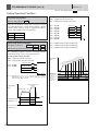
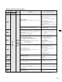
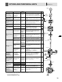
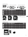
1
YASKAWA
COMPACT INVERTER FOR GENERAL-USE
VS mini J7
TIFIE
D
EM
ER
A
GE
ST
MAN
Certified for
ISO9001 and
ISO14001
C
200V CLASS (THREE-PHASE) 0.1 TO 3.7kW (0.13 TO 5HP)
200V CLASS (SINGLE-PHASE) 0.1 TO 1.5kW (0.13 TO 2HP)
400V CLASS (THREE-PHASE) 0.2 TO 3.7kW (0.25 TO 5HP)
Y
MENT S
QUALITY SYSTEM
JQA-0403 JQA-EM0498
LITERATURE NO. KAE-S606-12E
Inverter Magic
Instant Upgrade for Your Small Machinery!
The VS mini J7 inverter delivers the solution for all those users who want to easily upgrade small machinery to
variable-speed drives. Turn your machinery into the optimum drive through our powerful performance and rich array of functions.
Try the compact, economical VS mini J7 for simple operation and maintenance.
Only
128mm
Tall
Compact design means it fits into your panel efficiently. And with
global specifications: certified under UL/cUL and CE standards,
they are available in both 200V (3-phase/single-phase) and 400V
(3-phase) series. Power supply harmonics are also controlled so
our inverters can be used safely anywhere in the world.
CE marking for
European safety
standards
Note: When using CE standard inverters,
the special EMC conformed noise
filter is required. Contact your
YASKAWA representative.
FEATURES
4
OPERATION METHOD
6
STANDARD
SPECIFICATIONS/
DIMENSIONS
8
STANDARD WIRING/
CONSTANTS LIST
11
PROGRAMMING
FEATURES
16
PROTECTIVE FUNCTIONS
28
NOTES ON USE
31
OPTIONS/PERIPHERAL
UNITS
35
Simple
Operation
The main circuit terminals are arranged in upper and lower rows, so
you can wire it up just like a contactor. For operation, just turn the
frequency volume setting knob. The entire design is user-friendly
through-and-through, such as one-touch cooling fan replacement.
Upgrade Your
Machinery
Because the motor can be fully controlled, it is easier than ever to
adjust conveyor and mixer speeds, or pump and fan flow rates.
Inverter functions deliver the optimum drive at a reasonable cost
(see application examples on page 5). Just snap it on, and just like
magic! Your inverter is transformed.
2
3
Major Features of the VS mini J7
Performance
and
Functions
Operability
Full-range automatic torque boost
Simple installation and wiring
●Delivers outsanding starting torque (150%/3Hz) for its
class, for smooth machinery start-up.
●The main circuit terminals are arranged in upper and
lower rows, so you can wire it up just like a contactor.
Outstanding starting torque characteristics
●Main and control circuit terminals are screw-type, for
simple wiring and improved reliability.
105%/1.5Hz
155%/ 3Hz
Motor: 200V, 0.4kW, 4-pole
300
●One-touch
mounting/detaching with DIN rail attach-
ments.
(%)
6Hz
10Hz
TORQUE
200
30Hz
60Hz
3Hz
100
1.5Hz
0
100
SPEED
1,000
2,000
(min-1)
Even for a single given machine, the required motor torque will
vary with the load conditions. The full-range automatic torque
boost function automatically adjusts V (voltage) in V/f as
required. The VS mini J7 can adjust V for the required torque
during acceleration as well as during constant-speed operation.
The inverter calculates the required torque automatically.
Full range of protective functions
●High-speed current-limiting function minimizes overcurrent trips (above 250% of rated current) for enhanced
tripless operation (restart after momentary power loss,
stall prevention function, fault retry, etc.)
●Inrush
Screw-type
terminals
Just wire it up and run!
●Frequency volume setting knob located on the control
panel (operator) as a standard feature. Immediate
operation after you supply power.
●If remote operation is required, the optional operator
and cable can be mounted on your control panel.
current suppression circuit buit-in.
Simple maintenance
Diverse operating methods and functions
●Multi-step
speed operation (up to nine steps),
UP/DOWN operation and jog operation.
● One-touch mounting and/
or detaching. The life of the
cooling fan is extended by a
cooling fan ON/OFF control.
●Full range of functions, including slip compensation,
overtorque detection and high-speed search.
Removable
cooling fan
Wide range of input/output
●Multi-function I/O terminals, 0-10V, 4-20mA or 0-20mA
inputs, as well as analog monitors are available.
●Application
freedom is increased since multi-function
inputs can be set to PNP or NPN.
Supprot for RS-232C and RS-485/422 (MEMOBUS protocol)
available as options.
4
Power supply high-harmonics suppressed
An optional DC reactor can be connected, and of
course AC reactors are also available.
Compact Size
128
(5.04)
Efficient layout in panel
design means smaller volume
requirements, and because dimensions are
uniform for all 128mm-height (5.04 inches)
models, your panel layout is simplified, too.
128
(5.04)
●Compact
Dimensions
in mm (inches)
78.5
(3.09)
137.5
(5.41)
68 (2.68)
108 (4.25)
(Example of 200V, three–phase, 0.1kW model)
(Example of 200V, three–phase, 1.5kW model)
200V 3-phase 0.1 to 0.75kW
Single-phase 0.1 to 0.4kW
200V 3-phase 1.5 to 3.7kW
Single-phase 0.75 to 1.5kW
(see page 9 for details)
Perfect for these applications:
■
Replacing contactors
Provides maintenance-free operation by eliminating
contacts.
■
Replacing single-phase motors
Improve efficiency by replacing a single-phase motor
with a 3-phase motor.
■
Machine standardization
By mounting an inverter, the same machine can be
used regardless of the frequency of the power supply
(50 or 60 Hz).
■
Food processing machinery
Multi-step speed operation (maximum of nine steps)
can be set in advance to handle a wide range of
processing operations and materials.
■
Conveyors
Prevent load from toppling with soft starts and stops,
using the multi-step speed features (maximum of nine
steps) to vary conveyor speed.
■Mass-flow
machinery (pumps and fans)
Smooth variation in motor rotation speed means
optimal flow rate control, delivering energy-saving
operation.
5
OPERATING DIGITAL OPERATOR
Display and Keypad Description
Digital Operator
Function Display LEDs
Selected function is lit (See the
functions below). Its data is
displayed on data display.
Data Display
Operation Key
Display Selection Key
Press to run the motor. The RUN
light is ON while running.
Switch functions among function
display LEDs.
Alarm LED
Enter Key
Enter data when setting constants.
After selecting constant No. at
PRGM mode, data are displayed.
Run LED
Increment Key
Frequency Setting Volume
Increase constant No. or data.
Set operational frequency with
volume.
Decrement Key
Decrease constant No. or data.
Stop/Reset Key
Press to stop the motor. If fault
occurs, reset the inverter.
Function Display LED Description
FREF
FOUT
IOUT
MNTR
Output current
monitoring
Multi-function
monitoring
F/R
LO/ RE
PRGM
Operator RUN command
FWD/REV selection
LOCAL/REMOTE
selection
Constant No./data
Frequency reference Output frequency
setting/monitoring
monitoring
6
Switching the Function LEDs
Changing the Constant Data
6 0.
0
Power ON
FREF
Changing the displayed data
• Example: Changing frequency reference from 60Hz to 30Hz
Frequency reference
setting/monitor (Hz)
DSPL
FOUT
3 0.
0
F R EF
F R EF
<
6 0.
0
6 0.
0
Frequency
reference: 60Hz
Output frequency
monitor (Hz)
3 0.
0
FR E F
ENTER
The data blinks
while changing
The data is
entered.
DSPL
0 0.
2
IOUT
Displaying the monitor (See the monitor lists below)
Output current
monitor (A)
• Example: Monitoring output voltage reference
DSPL
U04
U01
MNTR
MNTR Monitor
MNTR
ENTER
(Output frequency monitor)
<
FO
FWD/REV
run selection
<
Select U 04
Depress
or
key
to change constant no.
DSPL
F/R
200
DSPL
ENTER
Selecting the constant no.
DSPL
• Example: Setting the constant n02 (operation reference selection)
LO
N02
LO/RE Remote/local
selection
PR G M
N01
1
PRGM
PR G M
ENTER
Select n02
operation
reference
PRGM
0
<
<
DSPL
Initial setting "0"
for digital operator
reference
Constant no./data
DSPL
Note:
OR
Output voltage
reference is
displayed
N02
1
PRGM
PR G M
After 1sec, returns
to the constant no.
: Indicates display switching flow
during operation
: Indicates display switching flow
while stopped
ENTER
Select "1" for
control circuit
terminal reference
(Data blinks while changing)
The data is
entered
Monitor (MNTR) Lists
Constant No.
Monitor
U 01
Frequency reference (FREF)*
U 02
Output frequency (FOUT)*
U 03
Output current (IOUT)*
Output voltage (1V unit)
U 04
Example: 200V
U 05
U 06
U 07
DC voltage (1V unit)
Example: 300V
U 09
Input terminal status
Output terminal status
Fault history
(The last four faults are displayed.)
U 10
Software No.
(Four digits of PROM are displayed.)
Unit
Hz
Hz
A
V
V
—
—
—
Fault display method
•
Display format
: 3-digit, 7-segment LED
Fault description example: “UV1” is displayed at Uv1 fault.
“---” is displayed when there is no fault.
• Clearing fault history
Set the constant n01 to “6,” then the n01 data returns to the previous value.
Or initialize the constant, then n01 returns to the default setting.
—
* The digital operator LED is not lit.
7
STANDARD SPECIFICATIONS
Voltage Class
Model
CIMR-J7A=????
200V single-/ three-phase
Three20P1
phase
1
*
SingleB0P1
phase
Control Characteristics
Power
Supply
Output
Characteristics
Max. Applicable Motor Output*2
kW (HP)
Inverter Capacity kVA
Rated Output Current A
Max. Output Voltage V
20P4
20P7
21P5
400V three-phase
22P2
23P7
40P2
40P4
40P7
41P5
42P2
43P0
B0P2
B0P4
B0P7
B1P5
—
—
—
—
—
—
—
—
—
0.2
(0.25)
0.4
(0.5)
0.75
(1)
1.5
(2)
2.2
(3)
3.7
(5)
0.37
(0.5)
0.55
(0.75)
1.1
(1.5)
1.5
(2)
2.2
(3)
3.0
(4)
3.7
(5)
0.3
0.6
1.1
1.9
3.0
4.2
6.7
0.9
1.4
2.6
3.7
4.2
5.5
6.5
1.2
1.8
3.4
4.8
5.5
7.2
8.6
0.8
1.6
3
5
8
11
17.5
3-phase, 200 to 230V (proportional to input voltage)
Single-phase, 200 to 240V (proportional to input voltage)
3-phase, 380 to 460V (proportional to input voltage)
400Hz (Programmable)
3-phase, 380 to 460V, 50/60Hz
-15 to +10%
Allowable Frequency Function
±5%
Control Method
Sine wave PWM (V/f control)
Frequency Control Range
0.1 to 400Hz
Frequency Accuracy
(Temperature Change)
Digital reference: ±0.01% (-10 to +50°C),
Analog reference: ±0.5% (25±10°C)
Frequency Setting
Resolution
Output Frequency Resolution
Digital reference: 0.01Hz (less than 100Hz), 0.1Hz (100Hz or more)
Analog reference: 1/1000 of max. output frequency
Overload Capacity
150% rated output current for one minute
Frequency Reference Signal
0 to 10VDC (20kΩ), 4 to 20mA (250Ω), 0 to 20mA (250Ω) , frequency setting volume (selectable)
0.01Hz
Accel/Decel Time
0.1 to 999 sec. (accel/decel time are independently programmed)
Braking Torque
Short-term average deceleration touque*3 : 0.1, 0.2kW (0.13HP, 0.25HP):150% or more;
0.4/0.75kW (0.5HP,1HP): 100% or more;
1.5kW (2HP): 50% or more;
2.2kW (3HP) or more: 20% or more
Continuous regenerative torgue: Approx. 20%
V/f Characteristics
Possible to program any V/f pattern
Motor Overload Protection
Electronic thermal overload relay
Instantaneous Overcurrent
Motor coasts to a stop at approx. 250% of inverter rated current
Overvoltage
Undervoltage
Momentary Power
Loss
Motor coasts to a stop after 1 minute at 150% of inverter rated output current
Motor coasts to a stop if DC bus voltage exceed 410V
Motor coasts to a stop if DC bus voltage exceed 820V
Stops when DC bus voltage is approx. 200V or less
(approx. 160V or less for single-phase series)
Stops when DC bus voltage is approx. 400V or less
Following items are selectable: Not provided (stop if power loss is 15ms or longer), continuous operation
if power loss is approx. 0.5s or shorter, continuous operation
Cooling Fin Overheat
Protected by thermister
Stall Prevention
Individual level stall prevention can be set during acceleration or constant running, provided/not provided setting available during deceleration
Cooling Fan Fault
Protected by electronic circuit (fan lock detection)
Ground Fault
Protected by electronic circuit (operation level is approx. 250% of rated output current)
Power Charge
Indication
ON until the DC bus voltage becomes 50V or less. RUN lamp stays ON or digital operator LED stays ON.
(Charge LED is provided for 400V)
Multi-function
Input
Multi-function
Output
Display
Standard Functions
Four of the following input signals are selectable: Forward/reverse run (3-wire sequence), fault reset, external fault
(NO/NC contact input), multi-step speed operation, Jog command, accel/decel time select, external baseblock
(NO/NC contact input), speed search command, UP/DOWN command, accel/decel hold command, LOCAL/REMOTE selection,
communication/control circuit terminal selection, emergency stop fault, emergency stop alarm, self test
Following output signals are selectable (NO/NC contact output): Fault, running, zero speed, speed agreed, frequency detection
(output frequency ≤ or ≥ set value), during overtorque detection, minor error, during baseblock, operation mode, inverter run
ready, during fault retry, during undervoltage detection, reverse running, during speed seach, data output through communication
Full-range automatic torque boost, slip compensation, 9-step speed operation (max.), restart after momentary power loss, DC
injection braking current at stop/start (50% of inverter rated current, 0.5 sec, or less), frequency reference bias/gain, fault retry,
speed search, frequency upper/lower limit setting, overtorque detection, frequency jump, accel/decel time switch, accel/decel
prohibited, S-curve accel/decel, frequency reference with built-in volume, constants copy (option), MEMOBUS communications
(Option)
Status Indicator LED
RUN and ALARM provided as standard LED’s
Digital Operator
Available to monitor frequency reference, output frequency, output current
Terminals
Wiring Distance between
Inverter and Motor
Main circuit: screw terminals
Control circuit: plug-in screw terminal
100m (328ft) or less
Enclosure
Open chassis (IP20)
Cooling Method
Humidity
Cooling fan is provided for 200V, 0.75kW (1HP)(3-/single-phase), 400V, 1.5kW (2HP)(3-phase), others are self-cooling
90% RH or less (non-condensing)
Storage Temperature*4
-20 to +60°C (-4 to 140°F) (Temperature during shipping for short period)
Ambient Temperature
-10 to +50°C (-50 to 122°F) (non-freezing)
Elevation
Vibration
1000m (3280ft) or less
Up to 9.8m/S2 (1G) at 10 to 20Hz
Up to 2m/S2 (0.2G) at 20 to 50Hz
*1 Single-phase series inverter output is three-phase (for three-phase motors).
*2 Based on a standard 4-pole motor for max. applicable motor output. Select the inverter model whose rated current is larger than motor rated current.
*3 Shows deceleration torque for uncoupled motor decelerating from 60Hz with the shortest possible deceleration time.
8
43P7
0.1
(0.13)
Rated Input Voltage 3-phase, 200 to 230V, 50/60Hz
Single-phase, 200 to 240V, 50/60Hz
and Frequency
Allowable Voltage Function
Output Signals Input Signals
Protective Functions
Other Functions
20P2
Max. Output Frequency
Overload
Environmental
Conditions
VS mini J7
4–M4
2–M4
8.5
(0.34)
8.5
(0.34)
Figure 1
Voltage
Class
Capacity
kW (HP)
200V
Three-phase
200V
Single-phase
400V
Three-phase
0.1 (0.13)
0.2 (0.25)
0.4 (0.5)
0.75 (1)
1.5 (2)
2.2 (3)
3.7 (5)
0.1 (0.13)
0.2 (0.25)
0.4 (0.5)
0.75 (1)
1.5 (2)
0.37 (0.5)
0.55 (0.75)
1.1 (1.5)
1.5 (2)
2.2 (3)
3.0 (4)
3.7 (5)
Fig.
No.
1
2
Figure 2
Dimensions in mm (inches)
W
H
68
(2.68)
68
(2.68)
108
(4.25)
128
(5.04)
128
(5.04)
128
(5.04)
D
W1
70
56
(2.76) (2.20)
102 (4.16) 56
122 (4.80) (2.20)
129 (5.08) 96
154 (6.06) (3.78)
H1
H2
118
(4.65)
118
(4.65)
118
(4.65)
5
(0.20)
5
(0.20)
5
(0.20)
140(5.51) 128(5.04) 161(6.34) 128(5.04) 118(4.65) 5 (0.20)
1
2
2
68
(2.68)
108
(4.25)
108
(4.25)
140
(5.51)
70
(2.76)
112 (4.41)
128 129 (5.08)
(5.04) 154 (6.06)
81 (3.19)
99 (3.90)
128 129 (5.08)
(5.04)
154
(6.06)
161
128
(5.04) (6.34)
128
(5.04)
56
(2.20)
118
(4.65)
5
(0.20)
96
(3.78)
118
(4.65)
5
(0.20)
96
(3.78)
118
(4.65)
5
(0.20)
128
(5.04)
118
(4.65)
5
(0.20)
< Model Designation
Mass
kg (lb)
Fin
3.7
7.7
15.8
28.4
53.7
60.4
96.7
3.7
7.7
15.8
28.4
53.7
9.4
15.1
30.3
45.8
50.5
58.2
73.4
0.5 (1.1)
0.8 (1.76)
0.9 (1.98)
1.3 (2.83)
1.5 (3.31)
2.1(4.63)
0.5 (1.1)
0.9 (1.98)
1.5 (3.31)
1.0 (2.20)
1.1 (2.43)
1.5 (3.31)
2.1 (4.63)
Heat Loss W
Inside
Unit
9.3
10.3
12.3
16.7
19.1
34.4
52.4
10.4
12.3
16.1
23.0
29.1
13.7
15.0
24.6
29.9
32.5
37.6
44.5
< Capacity Code Designation
CIMR—J7AA20P1
Inverter
VS mini J7 series
No.
A
B
C
Type
With digital operator (with volume)
Without digital operator
With digital operator (without volume)
No.
Specifications
A
Japan domestic standards
Conformed to UL/cUL, CE marking.
Total Heat
Loss
13.0
18.0
28.1
45.1
72.8
94.8
149.1
14.1
20.1
31.9
51.4
82.8
23.1
30.1
54.9
75.7
83.0
95.8
117.9
20P10
No.
0P1
0P2
0P4
0P7
1P5
2P2
3P0
3P7
Applicable maximum motor output
0.1kW (0.13HP)
0.2kW (0.25HP)
0.4kW (0.5HP)
0.75kW (1HP)
1.5kW (2HP)
2.2kW (3HP)
3.0kW (4HP)
3.7kW (5HP)
No.
B
2
4
Voltage Class
Single-phase 200VAC
Three-phase 200VAC
Three-phase 400VAC
No.
B
2
4
Phase / Voltage
Single-phase 200VAC
Three-phase 200VAC
Three-phase 400VAC
No.
0P1
0P2
0P4
0P7
1P5
2P2
3P0
3P7
Applicable maximum motor output
0.1kW (0.13HP)
0.2kW (0.25HP)
0.4kW (0.5HP)
0.75kW (1HP)
1.5kW (2HP)
2.2kW (3HP)
3.0kW (4HP)
3.7kW (5HP)
No.
0
Protective structure
Open chassis (IP20)
< Models
Voltage
class
Single-phase
200V
Three-phase
200V
Three-phase
400V
Description
With Analog Volume
With Digital
Operator
Without Analog Volume
Without Digital Operator
With Analog Volume
With Digital
Operator
Without Analog Volume
Without Digital Operator
With Analog Volume
With Digital
Operator
Without Analog Volume
Without Digital Operator
Note: Models without cooling fin are available.
Contact your YASKAWA representative.
Model
CIMR-J7A=B
CIMR-J7C=B
CIMR-J7B=B
CIMR-J7A=2
CIMR-J7C=2
CIMR-J7B=2
CIMR-J7A=4
CIMR-J7C=4
CIMR-J7B=4
Capacity code to be filled in model
0P1
0P2
0P4
0P7
(0.1) (0.2) (0.4) (0.7)
(Max. applicable motor output kW)
1P5
2P2
3P0
3P7
(1.5) (2.2) (3.0) (3.7)
>
>
>
>
>
—
—
—
>
>
>
>
>
—
—
—
>
>
>
>
>
>
—
>
>
>
>
>
>
>
—
>
—
>
>
>
>
>
>
>
—
>
>: provided
>
>
>
>
>
>
9
STANDARD WIRING
VS mini J7
DC REACTOR (OPTION)
U
X
SHORT
BAR
MCCB
1 R/L1
S
S/L2
T
T/L3
FORWARD RUN/STOP
U/T1
VS mini J7
V/T2
GROUNDING
S2
FAULT RESET
IM
W/T3
S1
REVERSE RUN/STOP
MULTIFUNCTION
INPUT
2
R
S3
EXTERNAL FAULT
(NO CONTACT)
MULTI-STEP SPEED
REFERENCE 1
MA
S4
MB RUNNING
MC
S5
MULTI-FUNCTION
OUTPUT
250VAC 1A OR ESS
30VDC 1A OR LESS
SC
PULSE TRAIN INPUT
FREQUENCY
REFERENCE
2kΩ
P
P
SHIELDED CONNECTION
TERMINAL
FS FREQUENCY SETTING POWER SUPPLY
(12V 20mA)
FR SPEED FREQUENCY REFERENCE
0 TO 10V (20kΩ) OR 4 to 20mA (250Ω)
FC
FREQUENCY SETTER
0V
DIGITAL OPERATOR
FREQUENCY
SETTING
VOLUME
MIN MAX
AM
AC
FREQUENCY METER
ADJUSTING POTENTIOMETER
ANALOG MONITOR
P FM OUTPUT
0 TO 10VDC (2mA)
OUTPUT FEQUENCY
indicates shielded wire.
P
< Model Description
: shows the connection for the following two kinds of sequence input (S1 to S5)
siglals: no-voltage contact and NPN transistors (0V common).
For a PNP transistor (+24V common), a 24V external power supply is necessary.
Terminal
Name
R/L1, S/L2, T/L3
AC Power Supply Input
Function (Signal Level)
Main circuit power supply input (Use R/L1 and S/L2 for single-phase power supply
inverter. Do not use T/L3 of the models less than 0.75kW for other usage,
such as a junction terminal.)
For inverter output
+2, +1
DC Reactor Connection
Remove the short bar between +2 and +1 when connecting DC reactor (option)
+1, –
DC Power Supply Input
For power supply input (+1: positive electrode; – : negative electrode)*
Sequence
U/T1, V/T2, W/T3 Inverter Output
Multi-function
Frequency
Contact
Reference
Output
Output
Control Circuit
Input
Main Circuit
Type
indicates twisted pair
shielded wire.
Grounding
For grounding (Grounding should be conforming to the local grounding code.)
S1
Forward Run Input
Runs when CLOSED, stops when OPEN.
S2
Multi-function Input Selection 2
Factory setting: Runs when CLOSED, stops when OPEN.
S3
Multi-function Input Selection 3
Factory setting: “Fault reset”
S4
Multi-function Input Selection 4
Factory setting: “External fault (NO contact)”
S5
Multi-function Input Selection 5
Factory setting: “Multi-step speed reference 1”
SC
FS
Multi-function Input Selection Common Common for control signal
Power Supply Terminal
+12V (allowable current: 20mA max.)
for Frequency Setting
FR
Speed Frequency Reference
0 to +10V DC (20kΩ) or 4 to 20mA (250Ω), 0 to 20mA (250Ω) (resolution 1/1000)
FC
Frequency Reference Common
0V
MA
NO Contact Output
MB
NO Contact Output
MC
Contact Output Common
Factory setting: “Running”
AM
Analog Monitor Output
Factory setting: “Output frequency” 0 to +10V output
AC
Analog Monitor Common
0V
*DC power supply input terminal is not conformed to CE and UL/cUL standards.
10
24VDC, 8mA
photocoupler
insulation
Contact capacity
250VAC, 1A or less
30VDC, 1A or less
0 to 10V 2mA or less
Resolution: 8bits
CONSTANTS LIST
Function
Constant No.
n==
VS mini J7
Function Name
Description
Setting
Range
Min.
Setting
Unit
Initial
Ref.
Page
0, 1, 6,
8, 9
1
1
17
0 to 2
1
0
01
Password
0 : n01 read and set, n02 to n79 read only
(FREF of digital operator can be set)
1 : n01 to n79 read and set
6 : Fault history clear
8 : Initialization-reset (multi-function terminal to initial setting)
9 : 3-wire initialization-reset
02
Run command
selection
0 : Digital operator
1 : Control circuit terminal
2 : Communication
03
Frequency
reference
selection
0 : Volume
1 : Frequency Reference 1 (n21)
2 : Control circuit terminal (0 to 10 V)
3 : Control circuit terminal (4 to 20 mA)
4 : Control circuit terminal (0 to 20 mA)
6 : Communication
Selecting
Stopping
Method
04
Selecting
Stopping
Method
Reverse Run
Prohibited
05
Selecting
Constant
Group
Initializing
Selecting
Operation
Mode
Selecting
Digital
Operator Key
Function
0 to 4.6
1
0*1
0 : Deceleration to stop
1 : Coast to a stop
0, 1
1
0
23
Selecting reverse
run prohibited
0 : reverse run enabled
1 : reverse run disabled
0, 1
1
0
17
06
Stop key function
0 : Stop key is always effective
1 : Stop key is effective when operated from digital operator
0,1
1
0
23
07
Selecting frequency
0 : Volume
reference in local mode 1 : Frequency reference 1 (n21)
0, 1
1
0*1
–
08
Frequency
reference setting
method from
digital operator
0, 1
0
–
09
Setting V/f
Pattern
17
0 : Enter key used
1 : Enter key not used
Max. output
frequency
50.0 to
400Hz
V
10
Max. voltage
n10
0.1 to
255V*2
11
Max. voltage
output frequency
(base frequency)
n13
0.2 to
400Hz
12
Mid. output
frequency
13
Mid. output
frequency voltage
14
Min. output
frequency
15
Min. output
frequency voltage
n15
0.1 to
399Hz
F
0
n14
n12
n11
n09
When V/f pattern is a straight line, set n12 and n14 to the
same value. In this case, n13 is disregarded.
*1 The factory setting of inverters with operator without volume (JVOP-146) is “1”. When initialized, turn to “0”.
*2 For 400V class inverter, the upper limit of voltage setting range and the setting value before shipment are twice
0.1Hz
(less than
100Hz)
60.0Hz
1Hz
(100Hz or
more)
1V
16
25
200V*2
0.1Hz
(less than 60.0Hz
100Hz)
1Hz
(100Hz or 1.5Hz
more)
0.1 to
255V*2
1V
0.1 to
10Hz
0.1Hz
1.5Hz
0.1 to
50V*2
1V
12V*2
12V*2
25
that of (=400/200) 200V class.
11
CONSTANTS LIST (Cont'd)
Function
Selecting
Acceleration/
Deceleration
Time
Constant No.
n==
Function Name
16*
Acceleration time 1
17*
18*
19*
Selecting
S-curve
Frequency
Reference
( FREF )
Frequency
Reference
Limit
Motor
Protection by
Electronic
Thermal
Selecting
Cooling Fan
Operation
Description
Sets acceleration time in the unit when frequency reference
changes from 0 to 100 %.
Setting
Range
Min.
Setting
Unit
0.0 to 999
Initial
10.0s
10.0s
S-curve selection
0 : S-curve not provided
1 : 0.2 s
2 : 0.5 s
3 : 1.0 s
21*
Frequency reference 1
(Master speed
frequency reference)
Sets master speed frequency reference. Setting is the same as
simple operation lamp FREF ).
22*
Frequency
reference 2
Sets second frequency reference. It is effective when multi-step
speed reference 1 is selected in multi-function contact input.
23*
Frequency
reference 3
Sets third frequency reference. It is effective when multi-step
speed reference 2 is selected in multi-function contact input.
24*
Frequency
reference 4
Sets fourth frequency reference. It is effective when multi-step speed
references 1 and 2 are selected in multi-function contact input.
25*
Frequency
reference 5
Sets fifth frequency reference. It is effective when multi-step
speed reference 3 is selected in multi-function contact input.
26*
Frequency
reference 6
Sets sixth frequency reference. It is effective when multi-step speed
references 1 and 3 are selected in multi-function contact input.
27*
Frequency
reference 7
Sets seventh frequency reference. It is effective when multi-step speed
references 2 and 3 are selected in multi-function contact input.
28*
Frequency
reference 8
Sets eighth frequency reference. It is effective when multi-step speed
references 1, 2, and 3 are selected in multi-function contact input.
29*
Jog frequency
Sets jog frequency. It is effective when jog frequency is
selected in multi-function contact input.
30
Frequency reference
upper limit
Sets upper limit of frequency reference in units of 1 %.
Max. output frequency (n09) is 100 %.
0 to 110%
1%
100%
31
Frequency reference
lower limit
Sets lower limit of frequency reference in units of 1 %.
Max. output frequency (n09) is 100 %.
0 to 110%
1%
0%
32
Motor rated current
Sets motor rated current of the motor nameplate. It is the
standard current for motor electro-thermal protection.
0 to 120 % of
inverter rated
output current
0.1A
Different
according to
inverter
capacity (kVA)
33
Electronic thermal
motor protection
selection
0 : Standard motor
1 : Inverter motor
2 : No protection
0 to 2
1
0
34
Electronic thermal
Sets constant for motor protection. For standard and inverter
motor protection time motors (standard rating), 8min., for others (short period rating), 1 to 60min
constant setting
5min.
35
Selecting cooling
fan operation
0 : ON/OFF control (ON while running, OFF when stopped.
ON for one minute after stopping.)
1 : Operates with power supply ON
1
16
19
10.0s
20*
0 to 3
Ref.
Page
10.0s
0.1s
Sets deceleration time in the unit when frequency reference
Deceleration time 1
0.0 to 999 (less than
changes from 100 to 0 %.
100s)
1s
Effective when acceleration time 2 is selected at multi-function
Acceleration time 2
0.0 to 999 (100s or
contact input selection. Setting is the same as n16.
more)
Effective when deceleration time 2 is selected at multi-function
Deceleration time 2
0.0 to 999
contact input selection. Setting is the same as n17.
* Can be changed during operation.
12
VS mini J7
0
20
6.0Hz
0.0 to
400Hz
0.1 Hz
(less than
100Hz)
1 Hz
(100 Hz or
more)
18
0.0Hz
6.0Hz
18
19
19
0.1
17
27
27
1min
8min
1
0
–
Function
Constant No.
n==
36
Multi-function input
selection 2
(Terminal S2)
Selecting
Sequence
Input
Functions
Selecting
Sequence
Output
Functions
Selecting
Frequency
Reference
Functions
Min.
Setting
Unit
Initial
2 : REV run command (2-wire sequence)
3 : External fault (NO contact input)
4 : External fault (NC contact input)
5 : Fault reset
6 : Multi-step speed reference 1
7 : Multi-step speed reference 2
8 : Multi-step speed reference 3
10 : Jog reference
11 : Accel/Decel time selection
12 : External baseblock (NO contact input)
13 : External baseblock (NC contact input)
14 : Search command from maximum. output frequency
15 : Search command from set frequency
16 : Accel/Decel prohibit
17 : Local/Remote selection
18 : Comm./Control circuit terminal selection
19 : Emergency stop fault (NO contact input)
20 : Emergency stop alarm (NO contact input)
21 : Emergency stop fault (NC contact input)
22 : Emergency stop alarm (NC contact input)
2 to 8
10 to 22
1
2
Description
Ref.
Page
18
19
21
22
23
37
Multi-function input
selection 3 (Terminal S3)
0 : FWD/REV run command (3-wire sequence)
Other set items are same as n36
0.2 to 8,
10 to 22
1
5
38
Multi-function input
selection 4 (Terminal S4)
Set items are same as n36
2 to 8
10 to 22
1
3
39
Multi-function input
selection 5
(Terminal S5)
2 to 8
10 to 22
34, 35
1
6
40
Multi-function
output selection 1
(Contact output
terminal
MA-MB-MC)
Set items are same as n36.
34 : UP/DOWN command (Terminal S4 is UP command/DOWN command and the
setting of n38 is invalid)
35 : Loop test (MEMOBUS)
0 : Fault
1 : Running
2 : Speed agreed
3 : Zero speed
4 : Frequency detection 1 ( Output frequency ≧ Custom frequency detection)
5 : Frequency detection 2 (Output frequency ≦ Custom frequency detection)
6 : Overtorque detection (NO contact output)
7 : Overtorque detection (NC contact output)
10 : Minor fault (alarm displays)
11 : During baselock
12 : Operation mode
13 : Inverter operation ready
14 : During fault retry
15 : Low voltage detecting
16 : In REV running
17 : Speed searching
18 : Output from communication
0 to 7
10 to 18
1
1
25
41*
Analog frequency
reference gain
Sets internal reference level in units of 1 % when frequency reference voltage
(current) is 10V (20mA). Max. output frequency (n09) is 100 %.
0 to 225%
1%
100%
19
42*
Analog frequency
reference bias
Sets internal reference level in units of 1 % when frequency reference voltage
(current) is 0V (4mA or 0mA). Max. output frequency (n09) is 100 %.
–99 to
99%
1%
0%
19
Sets filter time constant for analog input primary lag. (to avoid noise)
0.00 to
2.00s
0.01s
0.10s
–
0, 1
–
0
22
0.00 to
2.00
0.01
1.00
22
43
Selecting
Analog
Monitor
Functions
Setting
Range
Function Name
44
45*
Filter time constant for
analog frequency
reference constant
Multi-function analog
output
(terminal AM-AC)
Analog monitor gain
0 : Output frequency (10V/Max. frequency n09)
1 : Output current (10V/Inverter rated current)
Adjusts output voltage level of analog monitor. (ex.) when 3V is 100 % level,
sets as n45 = 0.30
* Can be changed during operation.
13
CONSTANTS LIST (Cont'd)
Function
Constant No.
n==
Function Name
Description
Setting
Range
Min.
Setting
Unit
Initial
Ref.
Page
Adjusting
Carrier
Frequency
46
Carrier
frequency
selection
Carrier frequency
1, 2, 3, 4 : Set value ×2.5 Hz
7, 8, 9 : Proportional to output frequency of 2.5 kHz max.
(lower limit 1 kHz)
1 to 4
7 to 9
1
( )
22
Momentary
Power Loss
Ridethrough
47
Momentary power
loss ridethrough
method
0 : Not provided
1 : Continuous operation after power recovery within the power loss
ridethrough time.
2 : Continuous operation after power recovery (no fault output of UV1)
0 to 2
1
0
20
Fault Retry
48
Automatic retry
attempts
Sets automatic retry times after self-diagnosis when an inverter
fault occurs.
0 to 10
1
0
20
49
Jump frequency 1
0.0Hz
21
Jump
Frequency
Control
DC Injection
Braking
Stall
Prevention
Frequency
Detection
Detecting
Overtorque
Sets frequency to jump. Disabled when setting value is 0.0.
50
Jump frequency 2
51
Jump frequency
range
Sets the frequency range to jump. Disabled when setting value
is 0.00.
52
DC injection
braking current
Sets current value at DC injection braking. Inverter rated
current is 100 %.
53
DC injection
braking time at
stop
54
DC injection
braking time at
start
55
Stall prevention
0 : Enabled
during deceleration 1 : Disabled
56
Stall prevention
level during
acceleration
57
Stall prevention
level during
running
4
0.0 to
400Hz
Different
according to
inverter
capacity (kVA)
0.1 Hz
(less than
100 Hz)
1 Hz
( 100 Hz or
more)
0.0 to
25.5Hz
0.01Hz
0 to 100%
1%
50%
21
23
Sets DC injection braking time at ramp to stop in units of 0.1
sec. Disabled at stop when the setting value is 0.0.
0.0 to
25.5s
0.1s
0.5s
23
Sets DC injection braking time at start in units of 0.1 sec.
Disabled at start when the setting value is 0.0.
0.0 to
25.5s
0.1s
0.0s
21
0, 1
1
0
30 to
200%
1%
170%
30 to
200%
1%
160%
0.0Hz
21
20
Sets stall prevention level in units of 1 % during acceleration.
Inverter rated current is 100 %
(Notes: ・Disabled with setting of 200 %.
・In constant output area, prevention level is automatically lowered.)
Sets stall prevention level in units of 1 % during running.
Inverter rated current is 100 %.
(Note:Disabled with setting of 200 %)
Frequency
detection (multifunction contact
output)
Sets frequency to detect when selected frequency detection at
multi-function contact output .
0.0 to
400Hz
0.1 Hz
(less than
100 Hz)
1 Hz
(100 Hz or
more )
59
Overtorque
detecting function
selection
0 : Detection disabled
1 : Detected during constant-speed running, and operation continues during and
after detection.
2 : Detected during constant-speed running, and inverter output is shut OFF
after detection.
3 : Detected during running, and operation continues during and after detection.
4 : Detected during running, and inverter output is shut OFF after detection.
0 to 4
1
0
60
Overtorque
detection level
Sets overtorque detection level when detecting at multifunction contact output and multi-function photocoupler output.
• Inverter rated current is 100% when detecting by current.
• Motor rated torque is 100% when detecting by torque.
30 to
200%
1%
160%
Overtorque
detection time
Sets overtorque detection time. Overtorque is detected when
the set time or the overtorque detection level setting is
exceeded.
0.1 to
10.0s
58
Detecting
Overtorque
61
14
VS mini J7
26
20
0.1s
0.1s
Function
Holding
Output
Frequency
Torque
Compensation
Constant No.
n==
62
Function Name
Hold output
frequecy saving
selection
Description
Selects whether or not to save the frequency when holding at
UP/DOWN command from multi-function input terminal.
0 : Output frequency is not saved while holding
1 : When holding more than 5 sec, saves output frequency at
holding and operates at this frequency when restarted.
Setting
Range
Min.
Setting
Unit
Initial
Ref.
Page
0, 1
1
0
–
0.0 to 2.5
0.1
1.0
25
0.0 to
20.0Hz
0.1Hz
63*1
Torque
Sets torque compensation gain in units of 0.1. Normally, no
compensation gain adjustment necessary.
64*1
Motor rated slip
Sets motor rated slip in units of 0.1 Hz.
Motor no-load
current
Sets motor no-load current proportional to the motor rated
current.
0 to 99%
1%
66*1
Slip compensation
gain
For motor slipping calculated from the output current, sets gain
to correct output frequency in units of 0.1.
0.0 to 2.5
67
Slip compensation
time constant
Adjusts for unstable speed and slow speed response.
68
MEMOBUS time
over detection
0 : Time over detection is enabled. (Coast to a stop)
1 : Time over detection is enabled. (Ramp to stop-Decel. 1)
2 : Time over detection is enabled. (Ramp to stop-Decel. 2)
3 : Time over detection is enabled. (Continue operation - alarm)
4 : Time over detection is disabled.
69
0 : 0.1 Hz
MEMOBUS frequency
1 : 0.01 Hz
reference and frequency
2 : 30000/100% (30000=MAX. output frequency)
monitor unit
3 : 0.1 %
70
MEMOBUS slave
address
71
MEMOBUS BPS
selection
72
0 : Even parity
MEMOBUS parity
1 : Odd parity
selection
2 : No parity
73
Transmission
waiting time
74
RTS Control
75
Reducing carrier
0 : Invalid
frequency selection
1 : Valid
at low speed
76
Constant copy
function selection
rdy : READY
rEd : READ
Cpy : COPY
77
Constant Read
selection prohibit
0 : READ prohibited
1 : READ allowed
Fault History
78
Fault history
Software
Version
79
Software Version
No.
Slip
Compensation
Function
MEMOBUS
Communication
(when
option
unit is
provided)
Carrier
Frequency
Selection*2
65
Control Copy
Function*2
(
(
)
)
Different
according to
inverter
capacity (kVA)
–
Different
according to
inverter
capacity (kVA)
27
0.1
0.0
27
0.0 to
25.5s
0.1s
2.0s
–
0 to 4
1
0
–
0 to 3
1
0
–
Allocates inverter MEMOBUS communication slave address
between 0 to 32.
Note: When set “0,” ignores command from master and does
not respond.
0 to 32
1
0
–
0 : 2400 bps
1 : 4800 bps
2 : 9600 bps
3 : 19200 bps
0 to 3
1
2
–
0 to 2
1
0
–
0 to 65ms
1ms
10ms
–
0, 1
1
0
–
0, 1
1
0
–
rdy, rEd
cPy, uFu
vA, Sno
–
rdy
–
0.1
1
0
–
Displays newest one fault (only for monitoring)
–
–
–
–
Displays lowest 3 digits of software No. (only for monitoring)
–
–
–
–
0 : Enabled
1 : Disabled (RS-422: at 1 to 1 communication)
vFy : VERIFY
vA : Inverter capacity display
Sno : software No. display
*1 Can be changed during operation.
*2 Not built in for the software virsion VSP020010.
15
PROGRAMMING FEATURES
VS mini J7
The set value displayed in
Programming features of VS mini J7 are explained
according to the following items.
is factory setting.
Items Should be Verified Before Operation
Accel/decel time setting
Item
Items Should
be Verified
Before
Operation
Setting
Operating
Condition
Selecting
Stopping
Method
Building
Interface
Circuits with
External
Devices
Accel time 1, 2 N16 N18
• Accel/decel time setting
• V/f pattern setting
• Motor rotation direction setting
• LOCAL (operator) /REMOTE
(control circuit terminal) selection
• Motor rated current setting
• Operation mode selection
• Constant set-up
16
16
17
17
Decel time 1, 2 N17 N19
• Reverse run prohibit
• Multi-step speed selection
• Adjusting frequency setting signal
• Operation at low speed
• Adjusting frequency upper and
lower limits
• Using two accel/decel times
• Automatic restart after momentary
power loss
• Soft-start characteristics
• Torque detection
• Continuing operation by automatic
fault reset
• Frequency detection
• Avoiding resonance
• Operating coasting motor without trip
• Holding accel/decel temporarily
• Using frequency meter or ammeter
• Reducing motor noise or leakage current
18
18
19
19
19
• Operator stop key selection
• Selecting stopping method
• Applying DC injection braking
23
23
23
Setting Function
17
17
17
19
20
20
20
20
21
21
21
22
22
22
Accel time : Sets the time needed for the motor to
accelerate to the maximum output
frequency from the stopped status.
Decel time : Sets the time needed for the motor to
stop from the maximum output frequency.
FREQUENCY
MAX. OUTPUT
FREQUENCY
TIME
ACCEL TIME
(n16)
RUN
COMMAND
DECEL TIME
(n17)
ON
V/f pattern setting
Max. output frequency
N09
Max. voltage
N10
Max. voltage output frequency N11
Sets the V/f pattern which matches the motor characteristics.
When operating at 50/60Hz or more frequency, change only
the max. output frequency (n09) as follows.
n10
=200V
CONSTANT CONSTANT OUTPUT
OR VARIABLE OUTPUT
TORQUE
BASE
POINT
• Using input signals
• Using output signals
23
25
• Adjusting torque according to application
• Preventing motor from stalling
(current limit)
25
26
Decreasing
Motor Speed
Fluctuation
• Slip compensation
27
Protecting
Motor
• Motor overload detection
27
Adjusting
Motor Torque
16
Ref.
Page
n11=60Hz
n09=90Hz
Motor rotation direction setting
Operation mode selection
FWD/REV direction selection F/R
Run command selection
Sets the motor rotation direction when run command is
given by the digital operator.
FWD and REV run can be switched by pressing ^ or
v key.
(
)
(
FWD
RUN
REV
RUN
)
LOCAL (operator)/REMOTE (control circuit
terminal) selection
LOCAL/REMOTE switching LO/RE
Operation can be switched from digital operator or
control circuit terminal. This function is valid only when
stopped.
e.g. : Digital operator/control circuit terminal selection:
Operation mode selection
n02=1
Frequency reference selection n03=2, 3 or 4
Local (LO) : Receives frequency reference (set at
n07) and run command from digital
operator
Remote (RE) : Receives frequency reference (FR)
and run command (terminals S1
and S2) of circuit control terminal
* When local/remote selection function is allocated to
multi-function input terminal, switching operation
using ^ and v keys is invalid.
N02
Frequency reference selection N03
Selects whether operation is performed by digital
operator or control circuit terminal.
Setting
Run Command
N02
0
Operator
1
Control circuit terminal S1, S2
2
Communication
Setting
Frequency Reference
N03
0
Volume
1
Operator (Frequency reference 1) N21
2
Control circuit terminal FR (0 to 10V)
3
Control circuit terminal FR (4 to 20mA)
4
Control circuit terminal FR (0 to 20mA)
6
Communication (register No., 0002H)
Notes : When set to 2 or 3 (current input reference), dip switch setting
must be changed. For details, refer to the instruction manual.
Constant set-up
Password N01
The following table describes the data which can be set
or read when n01 is set.
Setting
Constant
0
Only n01 can be set, n01 to n79 can be read
(Constant write disable)
Motor rated current setting
Motor rated current N32
Sets motor rated current. The following table shows the
standard set value for each inverter capacity. When the
applicable motor rated current value differs from the
value listed below, change the set value.
1
n01 to n79 read/set
6
Fault history clear
8*
Constant initialization (factory setting: 2-wire sequence)
9*
Constant initialization (3-wire sequence)
* Initialization resets the value to factory setting.
VS mini J7 model 20P1 20P2 20P4 20P7 21P5
22P2 23P7
B0P1 B0P2 B0P4 B0P7 B1P5
CIMR-J7??
Max. Applicable Motor 0.1 0.2 0.4 0.75
Output
kw(HP) (0.13) (0.25) (0.5) (1)
Motor Current Factory
0.6 1.1 1.9 3.3
Setting
A
1.5
(2)
2.2
(3)
3.7
(5)
6.2
8.5
14.1
VS mini J7 model
40P2 40P4 40P7 41P5 42P2 43P0 43P7
CIMR-J7??
Max. Applicable Motor 0.37 0.55 1.1
Output
kw(HP) (0.5) (0.75) (1.5)
Motor Current Factory
0.6 1.0 1.6
Setting
A
1.5
(2)
2.2
(3)
3
(4)
3.7
(5)
3.1
4.2
7.0
7.0
17
PROGRAMMING FEATURES (Cont’d)
VS mini J7
The set value displayed in
is factory setting.
Setting Operating Condition
8-step speed change example
n02 = 1 (Operation mode selection)
n03 = 1 (Frequency reference selection)
Reverse run prohibit
Reverse run prohibit N05
“Reverse run disabled” setting does not accept a reverse
run command from the control circuit terminal or digital
operator. This setting is used for applications where a
reverse run command can cause problems.
Setting
Description
0
Reverse run enabled.
1
Reverse run disabled.
Multi-step speed selection
Frequency reference
FREF
N21 to N29
Multi-function input terminal function selection N36 to N39
n21 = 25.0 Hz
n22 = 30.0 Hz
n23 = 35.0 Hz
n24 = 40.0 Hz
n25 = 45.0 Hz
n26 = 50.0 Hz
n27 = 55.0 Hz
n28 = 60.0 Hz
FWD RUN/STOP
S1
REV RUN/STOP
S2
MULTI-STEP
SPEED REF. 1
S3
MULTI-STEP
SPEED REF. 2
S4
MULTI-STEP
SPEED REF. 3
S5
SC
n37 = 6 (Multi-function input terminal S3)
n38 = 7 (Multi-function input terminal S4)
n39 = 8 (Multi-function input terminal S5)
By combining frequency reference and input terminal
function selections, up to 9-step speed can be set.
2-step speed change example
n02 = 1 (Operation mode selection)
n03 = 1 (Frequency reference selection)
n21 = 30.0Hz
n22 = 50.0Hz
FWD RUN/STOP
FREQUENCY
REF.
S1
REV RUN/STOP
(n28) 60.0Hz
(n27) 55.0Hz
(n26) 50.0Hz
(n25) 45.0Hz
(n24) 40.0Hz
(n23) 35.0Hz
(n22) 30.0Hz
(n21) 25.0Hz
S2
MULTI-STEP SPEED REF. 1
S5
TIME
SC
Note : When n03 is set to 0, 2 ,3, or 4, frequency reference 1 (n21) is
disabled and frequency reference from volume (0) or control
circuit terminal (FR) is enabled.
FREQUENCY REF. 2 (n22)
50.0Hz
FREQUENCY
REF.
FREQUENCY REF. 1 (n21)
30.0Hz
TIME
FWD (REV)/STOP
[TERMINAL S1 (S2)]
ON
ON
MULTI-STEP SPEED REF.
(TERMINAL S5)
18
FWD (REV) RUN/STOP
[TERMINAL S1 (S2)]
MULTI-STEP SEED REF. 1
[TERMINAL S3]
MULTI-STEP SEED REF. 2
[TERMINAL S4]
MULTI-STEP SEED REF. 3
[TERMINAL S5]
ON
ON
ON
ON
ON
ON
ON
ON
Adjusting frequency upper and lower limits
Frequency reference gain N41
Frequency reference upper limit N30
Frequency reference bias N42
Frequency reference lower limit N31
When the frequency reference is output by analog input
of control circuit terminals FR and FC, the relation
between analog voltage and frequency reference can be
set.
FREQUENCY REF.
Frequency reference gain (n41)
The analog input voltage
OUTPUT
value for the maximum MAX.
FREQUENCY
output frequency (n09) can GAIN
100
be set in units of 1%.
Frequency reference upper
limit (n30)
Sets the upper limit of the
frequency reference in units of
1%.
Factory setting : 100%
Frequency reference bias (n42)
The frequency reference
provided when analog input
is 0V (4mA or 0mA) can be
set in units of 1%.
MAX. OUTPUT
FREQUENCY
BIAS
100
0V
10VGAIN
(4mA)
(20mA)
( ) indicates when current
reference input is selected.
• To operate the inverter
with frequency reference
of 50% to 100% at 0 to
10V input
50%
0V
5V
Gain: Constant n41=200
Bias: Constant n42=0
10V
0V
10V
Gain: Constant n41=100
Bias: Constant n42=50
Operating at low speed
Jog frequency reference FREF
N29
Jog command selection
N36 to N39
By inputting a jog command and then a forward
(reverse) run command, operation is enabled at the jog
frequency set in n29. When multi-step speed references
1, 2, or 3 are input simultaneously with the jog
command, the jog command has priority.
Name
When operating at frequency reference 0, operation continues
at the frequency reference lower limit.
However, when frequency reference lower limit is set to less
than the minimum output frequency (n14), operation is
disabled.
Using two accel/decel times
Accel time 1, 2
N16 N18
Decel time 1, 2
N17 N19
Input terminal function selection N36 to N39
ACCEL DECEL TIME 1 DECEL TIME 2
TIME 1 (n17)
(n18)
OUTPUT
DECEL TIME 2*
FREQUENCY (n16)
(n19)
DECEL TIME 1*
(n17)
TIME
MULTI-STEP SPEED REF.
ACCEL/DECEL
TIME SELECTION
(TERMINAL S2 TO S5)
0%
Jog frequency reference
Jog command
Frequency reference lower
limit (n31)
Sets the lower limit of the frequency reference in units of 1%.
FWD (REV) RUN COMMAND
MAX. OUTPUT
FREQUENCY
(100%)
50%
Constant no.
n29
n36 to n39
FREQUENCY
LOWER LIMIT
(n034)
SET FREQUENCY
REF.
Factory setting : 0%
Gain : Outputs A % (ratio to max. output frequency n09)
at 10V.
a n41 = A %
Bias : Outputs B % (ratio to max. output frequency n09)
at 0V.
a n42 = B %
MAX. OUTPUT
FREQUENCY
(100%)
FREQUENCY
UPPER LIMIT
(n033)
[n09 : Maximum output frequency = 100%]
[n09 : Maximum output frequency = 100%]
Factory setting : 0%
Typical Settings
• At 0 to 5V input
[n09 : Maximum output frequency
= 100%]
Factory setting : 100%
INTERNAL FREQUENCY
REF.
Adjusting frequency setting signal
Setting
Factory setting : 6.0Hz
Set to “10” for any constant.
ON
ON
ON
*When “deceleration to a stop” is selected (n04=0).
By setting input terminal function selection (one of n36
to n39) to “11” (accel/decel time select), accel/decel time
is selected by turning ON/OFF the accel/decel time
select (one terminal of S2 to S5).
At OFF : n16 (accel time 1)
n17 (decel time 1)
At ON : n18 (accel time 2)
n19 (decel time 2)
No.
Name
Unit*
n16
Accel time 1
0.1s
n17
Decel time 1
0.1s
n18
Accel time 2
0.1s
n19
Decel time 2
0.1s
* Setting unit is 1s when 100s or more.
Setting range
0.0 to 999s
0.0 to 999s
0.0 to 999s
0.0 to 999s
Initial setting
10.0s
10.0s
10.0s
10.0s
• Accel time
Set the time needed for output frequency to reach 100%
from 0%.
• Decel time
Set the time needed for output frequency to reach 0%
from 100%.
19
PROGRAMMING FEATURES (Cont’d)
VS mini J7
The set value displayed in
Automatic restart after momentary power loss
Torque detection
Operation selection after momentary power loss N47
Overtorque detection function selection N59
When momentary power loss occurs, operation restarts
automatically.
Setting
Description
Continuous operation after momentary power loss not provided.
0
Continuous operation after power recovery within 0.5 second.
1*
2*† Continuous operation after power recovery (Fault output not provided).
* Hold the operation command to continue the operation after
recovery from a momentary power loss.
† When 2 is selected, operation restarts if power supply voltage
reaches its normal level. No fault signal is output.
Overtorque detection level
N60
Overtorque detection time
N61
If excessive load is applied to the machine, output
current increase can be detected by output alarm signals
at multi-function output terminals MA, MB and MC.
To output overtorque detection signal, set multi-function
output terminal selection n40 to “overtorque detection
(set 6 or 7)”.
n60
S-curve accel/decel time selection N20
To prevent shock at machine start/stop, accel/decel can
be performed in S-curve pattern.
Setting S-curve characteristic time
0
S-curve characteristic not provided
1
0.2 second
2
0.5 second
3
1.0 second
Note : S-curve characteristic time is the time from accel/decel rate 0 to
a regular accel/decel determined by the set accel/decel time.
FREQUENCY
REF.
HYSTERESIS DURING
OVERTORQUE DETECTION
IS APPROX. 5% OF
INVERTER RATED
CURRENT
MOTOR
CURRENT
Soft-start characteristics
OUTPUT
FREQUENCY
MULTI-FUNCTION
OUTPUT SIGNAL
(OVERTORQUE DETECTION
SIGNAL)
TERMINAL MA, MB, P1
AND P2
(WHEN SETTING IS 6)
TIME
ON
n61
ON
n61
Overtorque detection function selection 1 (n59)
Setting
0
1
2
3
4
Description
Overtorque detection not provided.
Detected only during constant-speed running, and operation continues after detection.
Detected only during constant-speed running, and operation stops after detection.
Detected during running, and operation continues after detection.
Detected during running, and operation stops after detection.
Continuing operation by automatic fault reset
OUTPUT
FREQUENCY
TIME
S-CURVE CHARACTERISTIC TIME (Tsc)
Time chart at FWD/REV run switching at deceleration to
a stop
FWD RUN COMMAND
REV RUN COMMAND
OUTPUT
FREQUENCY
ACCEL
DECEL
MIN. OUTPUT
FREQUENCY
n14
DC INJECTION
BRAKING TIME
AT STOP
n53
MIN. OUTPUT
FREQUENCY n14
S-curve characteristic in
20
is factory setting.
ACCEL
DECEL
No. of fault retry times N48
Sets the inverter to restart and reset fault detection
[overcurrent (OC) or overvoltage (OV)] after a fault
occurs.
The number of self-diagnosis and retry attempts can be
set at n48 up to 10 times.
The number of retry attempts are cleared to 0 in the
following cases :
• If no other fault occurs within 10 minutes after retry
• When the fault reset signal is ON after the fault is detected
• Power supply is turned OFF
Frequency detection
Operating coasting motor without trip
Frequency detection level N58
Speed search command
Input terminal function selection N36 to N39
DC injection braking at start
N52
DC injection braking current
DC injection braking time at start N54
Effective when output terminal function selections n40,
are set to “frequency detection (setting : 4 or 5).
“Frequency detection” turns ON when output frequency
is higher or lower than the frequency detection level
(n58).
Frequency detection 1 (Output frequency Frequency
detection level)
(Set n40 to “4”)
RELEASE
WIDTH –2Hz
FREQUENCY DETECTION
LEVEL (Hz)
(n58)
OUTPUT
FREQUENCY
FREQUENCY
DETECTION
SIGNAL
ON
Frequency detection 2 (Output frequency
detection level)
(Set n40 to “5”)
RELEASE
WIDTH +2Hz
FREQUENCY DETECTION
LEVEL (Hz)
(n58)
OUTPUT
FREQUENCY
FREQUENCY
DETECTION
SIGNAL
Frequency
ON
ON
To operate coasting motor without trip, use the speed
search command or DC injection braking at start.
Speed search command
Restarts a coasting motor without stopping it. This
function enables smooth switching between motor
commercial power supply operation and inverter
operation.
Set input terminal function selection (n36 to n39) to
“14” (search command from maximum output
frequency) or “15” (search command from set
frequency).
Build a sequence so that FWD (REV) run command is
input at the same time as the search command or after
the search command. If the run command is input
before the search command, the search command
becomes disabled.
FWD (REV) RUN
COMMAND
SEARCH COMMAND
MAX. OUTPUT FREQUENCY
OR FREQUENCY REF.
AT RUN COMMAND
INPUT
Avoiding resonance
Jump frequency 1, 2 N49 N50
n49
n49
n50
n51
n51
FREQUENCY REF.
AGREED SPEED
DETECTION
MIN. BASEBLOCK SPEED SEARCH
TIME (0.5sec)
OPERATION
This function allows the prohibition or “jumping” of
critical frequencies so that the motor can operate without
resonance caused by machine systems. This function is
also used for dead band control. Setting the value to
0.0Hz disables this function.
Set jump frequency 1, 2 or 3 as follows:
OUTPUT FREQUENCY
ON
OUTPUT FREQUENCY
N51
Jump width
ON
0.5s OR MORE
n50
If this condition is not
satisfied the inverter
displays
for one
second and restores the
data to original settings.
Note : Gradually changes without
jumping during accel/decel.
Time chart at search command input
DC injection braking at start
(n52, n54)
n14
Restarts a coasting motor after MIN. OUTPUT
stopping it. Set DC injection FREQUENCY
braking time at start in n54 in
units of 0.1 second. Set DC
n54
DC INJECTION BRAKING
injection braking current in
TIME AT START
n52 in units of 1%. When the
setting of n54 is “0,” DC
injection braking is not performed and acceleration
starts from the minimum output frequency.
21
PROGRAMMING FEATURES (Cont’d)
VS mini J7
The set value displayed in
is factory setting.
Holding accel/decel temporarily
Reducing motor noise or leakage current
Accel/decel hold command
Carrier frequency N46
Input terminal function selection N36 to N39
To hold acceleration, input accel/decel hold command.
The output frequency is maintained when the aceel/decel
hold command is input during acceleration or
deceleration.
The stop command releases the accel/decel hold and the
operation ramps to stop while inputting accel/decel hold
command.
Set input terminal function selection (n36 to n39) to 16
(accel/decel hold command).
FWD RUN
COMMAND
ACCEL/DECEL
HOLD COMMAND
Sets inverter output transistor swiching frequency
(carrier frequency).
Setting Carrier frequency (Hz) Metallic noise from motor Current leakage
1
2.5
Higher
Smaller
5.0
2
7.5
3
10.0
Not audible
Larger
4
7 to 9
Synchronized type with lower limit
1kHz and upper limit 2.5Hz
–
–
ON
ON
ON
ON
fc=CARRIER FREQUENCY
fc=CARRIER FREQUENCY
2.5kHz
2.5kHz
FREQUENCY
REF.
1.0kHz
OUTPUT
FREQUENCY
ON
SPEED
AGREED SIGNAL
ON
1.0kHz
fc=12 fout
83.3Hz
208.3Hz
FOUT
n46=7
Time chart at accel/decel hold command input
fc=24 fout
41.6Hz
104.1Hz
FOUT
n46=8
fc=CARRIER FREQUENCY
Using frequency meter or ammeter
2.5kHz
Analog monitor selection N44
1.0kHz
N45
Analog monitor gain
Selects to output either output frequency or output
current to analog output terminals AM-AC for
monitoring.
Setting
0
1
Description
Output frequency
Output current
FREQUENCY METER
AM
FM
0 TO 10VDC
AC
• Example of analog monitor gain adjustment
When using a frequency meter (full scale : 3V, 1mA)
which indicates 0 to 60Hz at 0 to 3V.
OUTPUT FREQUENCY
(OUTPUT CURRENT)
100%
Analog monitor gain
can be set by n45
(When n45=0.30)
0
22
3V
ANALOG OUTPUT
10V
fc=32 fout
27.7Hz
69.4Hz
FOUT
n46=9
Carrier frequency initial value differs depending on
inverter capacity as follows :
• 10kHz (setting n46 = 4) : 200V three-phase 0.1 to 0.75kW
• 7.5kHz (setting n46 = 3) : 200V three-phase 1.5 to 3.7kW
200V single-phase, 1.5kW
400V three-phase, all models
To change the initial value 7.5kHz to 10kHz, continuous
output current must be lowered. For details, refer to the
instruction manual.
Selecting Method to Stop
Building Interface Circuits with External Devices
Operator stop key selection
Using input signals
Operator stop key selection N06
Input terminal function selection N36 to N39
Selects processing when STOP key is depressed during
operation from control circuit terminal or communication.
Multi-function input terminals S2 to S5 functions can be
changed when necessary by setting constants n36 to
n39, respectivery. The same value can not be set to
different constant setting.
Setting
Description
0
STOP key effective when running from terminals or communication.
When STOP key is depressed, the inverter stops according to the
setting of constant n04. At this time, the digital operator displays
“
” alarm (blinking). This stop command is held in the inverter
until both forward and reverse run commands are open or operation
command from communication is “0”.
1
STOP key ineffective when running from terminals or communication.
• Terminal S2 function : Set to n36 : Factory setting
• Terminal S3 function : Set to n37 : Factory setting
• Terminal S4 function : Set to n38 : Factory setting
• Terminal S5 function : Set to n39 : Factory setting
2
5
3
6
Selecting stopping method
Stopping method selection N04
Selects the stopping method suitable for application.
Setting
0
1
*
DECEL TIME 1 DECEL TIME 1
(n17)
(n17)
*
n14
(FACTORY SETTING: 1.5Hz)
TIME
FWD (REV)
RUN
COMMAND
ON
MIN. OUTPUT
FREQUENCY
(FREQUENCY AT
DC INJECTION BRAKING
START)
* When frequency reference
is changed during running.
DC INJECTION BRAKING
TIME AT STOP (n53)
(FACTORY SETTING: 0.5s)
• Coast to a stop
Example when accel/decel time 1 is selected
OUTPUT
ACCEL
FREQUENCY TIME 1
(n16)
*
*
COAST TO STOP
TIME
FWD (REV)
RUN
COMMAND
ON
* When frequency reference
is changed during running.
DC injection braking current
DC injection braking time at stop N53
When coasting to a stop is
specified in stopping method
selection (n04), DC injection
braking at stop does not operate.
n14
MIN. OUTPUT
FREQUENCY
24
–
–
6
Multi-step speed reference 1
–
7
Multi-step speed reference 2
–
8
Multi-step speed reference 3
–
10
Jog command
–
19
11
Accel/decel time select
–
19
Inverter stops by external
fault signal input.
Digital operator display
is “EF?*”
Resets fault. It is disabled
with run signal entered.
–
–
18
Motor coasts to stop by
this signal input.
Digital operator display
“BB” (blinking).
–
Speed search command
signal
21
15
External baseblock
(NO contact input)
External baseblock
(NC contact input)
Search command from max.
output frequency
Search command from set
frequency
16
Accel/decel hold command
–
22
17
LOCAL/REMOTE selection
–
24
18
Communication/Control
circuit terminal selection
Emergency stop fault
(NO contact input)
Emergency stop alarm
(NO contact input)
Emergency stop fault
(NC contact input)
Emergency stop alarm
(NC contact input)
–
24
12
13
20
N52
Setting enabled only for
n052
Fault reset
19
Applying DC injection braking
Ref.
Page
5
3
14
DECEL TIME 1
(n17)
Description
4
2
• Deceleration to stop
Example when accel/decel time 1 is selected
Function Name
FWD/REV run command
(3-wire sequence selection)
REV run command
(2-wire sequence)
External fault
(NO contact input)
External fault
(NC contact input)
0
Description
Deceleration to stop
Coast to stop
ACCEL
OUTPUT
FREQUENCY TIME 1
(n16)
Setting
21
22
34
UP/DOWN command
35
Self-test
Inverter stops by emergency stop
signal input according to stopping
method selection (n04). When
frequency deceleration to a stop
(n04=0) is selected, inverter
decelerates to a stop according to
decel time setting 2 (n19). Digital
operator displays “
” (lights at
fault, blinks at alarm).
Setting is enabled only
for n39.
Setting is enabled only
for n39.
–
–
–
–
24
–
* : A number 2 to 5 is displayed in ? corresponding to the number of
terminal S2 to S5 respectively.
n53
DC INJECTION BRAKING
TIME AT STOP
23
PROGRAMMING FEATURES (Cont’d)
VS mini J7
The set value displayed in
Terminal function at 3-wire sequence selection
STOP SW
(NC CONTACT)
RUN SW
(NO CONTACT)
S1 RUN COMMAND
(Run when “closed”)
S2 STOP COMMAND
(Stop when “open”)
S3 FWD/REV RUN SELECTION
FWD run when “open”
SC REV run when “closed”
(
is factory setting.
FWD RUN
UP COMMAND S4
DOWN COMMAND S5
UPPER LIMIT SPEED
LOWER LIMIT SPEED
OUTPUT FREQUENCY
)
D1H U
H
D
H
U
H
D
D1 H
U
D1 H
D
D1 H
FREQUENCY AGREED
SIGNAL
LOCAL/REMOTE select (setting : 17)
Select operation reference by the digital operator or by
the control circuit terminal.
LOCAL/REMOTE select is valid only during stop.
Open : Run by setting at run command selection (n02)
and frequency reference selection (n03).
Closed : Run by frequency reference and run command
from digital operator.
e.g. : When the digital operator/control circuit terminal
selection setting is n02 = 1 and n03 = 2, 3 or 4
Open : Receives frequency reference (terminal FR,
RP) and run command (terminals S1 to S5 )
from control circuit terminal
Closed : Receives frequency reference (setting at n07)
and run command from digital operator.
Communication/control circuit terminal selection
(setting : 18)
Selects operation reference by communication or by
control circuit terminal. Communication/control circuit
terminal selection is valid only during stop.
Open : Run according to the setting at n02 and n03
(operation method selection).
Closed : Run by frequency reference and run command
from communication.
e.g. : When used for communication/control circuit
terminal selection, set n02 = 1 and n03 = 2, 3
or 4
Open : Receives frequency reference (terminal FR)
and run command (terminals S1 to S5 ) from
control circuit terminal
Closed : Receives frequency reference and run
command from communication
UP/DOWN command (setting : n39 = 34)
With the FWD (REV) run command entered,
accel/decel is enabled by inputting the UP or DOWN
signals to control circuit terminals S4 and S5 without
changing the frequency reference, so that operation can
be perfomed at the desired speed. When UP/DOWN
commands are specified by n39, any function set to
n38 becomes disabled; terminal S4 becomes an input
terminal for UP command and terminal S5 for DOWN
command.
Control circuit terminal S4 (UP command) Closed
Control circuit terminal S5 (DOWN command) Open
Operation status
Accel
* : Effective only when with option unit.
24
Open
Closed
Decel
Open
Open
Hold
Closed
Closed
Hold
Time chart at UP/DOWN command input
U = UP (accelerating) status
D = DOWN (decelerating) status
H = HOLD (constant speed) status
U1 = UP status, clamping at upper limit speed
D1 = DOWN status, clamping at lower limit speed
Notes : • When UP/DOWN command is selected, the
upper limit speed is set regardless of
frequency reference.
Upper limit speed = Max. output frequency
(n09) × Frequency
reference upper limit
(n30) /100
• The lower limit speed is the largest value
among min. output frequency (n14) and
frequency reference lower limit (n31).
• When the FWD (REV) run command is input,
operation starts at the lower limit speed
without UP/DOWN command.
• When the jog command is input while running
by the UP/DOWN command, the jog
command has priority. The UP/DOWN
command can not be input together with
multi-step speed reference.
• By setting hold output frequency memory
selection (n62) to 1, the output frequency
during hold can be saved.
Setting at n62
Description
0
Output frequency during hold is not saved.
After 5 sec. of hold state, the output frequency
during hold is saved and the operation will
restart with the saved output frequency
1
Adjusting Motor Torque
Using output signals
Adjusting torque according to application
Multi-function output terminal function selection N40
Max. output frequency
Max. voltage
Max. voltage output frequency
Mid. output frequency
Mid. output frequency voltage
Min. output frequency
Min. output frequency voltage
Torque compensation gain
Multi-function output terminal MA and MB, functions
can be changed when necessary by setting constants
n40.
• Terminal MA and MB functions : Set to n40
Setting
Function Name
Description
Ref.
Page
Fault
“Closed” (ON) when
inverter fault occurs.
1
Running
“Closed” (ON) when FWD
or REV run command is
input, or when the inverter
outputs voltage.
–
2
Speed agreed
–
Figure
below
“Closed” (ON) when the
inverter output frequency
is less than min. output
frequency
–
0
3
Zero speed
4
(output frequency
Frequency detection 1
frequency detection level)
Frequency detection 2
5
(output frequency
frequency detection level)
–
–
21
–
–
7
10
Minor fault (alarm display)
–
28
11
During baseblock
“Closed” (ON) when the
inverter output is shut off.
–
12
Operation mode
“Closed” (ON) when
“LOCAL” is selected by
LOCAL/REMOTE
selection
–
13
Inverter run ready
“Closed” (ON) when the
inverter is ready to operate
without any fault.
–
14
In fault retry
15
Low voltage (UV) detected
16
In REV run
17
In speed search
18
Data output from communication terminal is operated independently
“Closed” (ON) during
fault retry.
“Closed” (ON) when the
inverter is detecting low
voltage.
–
–
“Closed” (ON) during
speed search of inverter.
21
By command from MEMOBUS
communication, multi-function output
from the inverter operation.
Factory settings n40 : 1
RELEASE WIDTH
±4Hz
FREQUENCY
REF
DETECTION
WIDTH ±2Hz
OUTPUT
FREQUENCY
SPEED AGREED
SIGNAL
ON
–
N13
N14
N15
N63
Be sure to satisfy the
following conditions for the
setting of n09 to n15.
n14 n12 < n11 n09
If n14 = n12 is set, the set
value of n13 is disabled.
n15
0
–
N12
V: VOLTAGE
n13
–
N11
V/f pattern setting
Set V/f pattern by n09 to n15 as described below. Set
each pattern when using a special motor (high-speed
motor, etc.) or when requiring special torque adjustment
of machine.
20
–
N10
Adjust motor torque by using “V/f pattern” and “fullrange automatic torque boost”.
n10
Overtorque detection
(NO contact output)
Overtorque detection
(NC contact output)
6
N09
n14 n12 n11
Constants
No.
n09
n10
n09
Name
f
FREQUENCY
Unit
Setting Range Initial Setting
Max. output frequency
0.1Hz 50.0 to 400Hz
Max. voltage
1V
1 to 255V
Max. voltage output frequency
0.1Hz
0.2 to 400Hz
n11 (base frequency)
n12 Mid. output frequency
0.1Hz
0.1 to 399Hz
n13 Mid. output frequency voltage 1V
1 to 255V
n14 Min. output frequency
0.1Hz 0.1 to 10.0Hz
n15 Min. output frequency voltage 1V
1 to 50V
Note : Refer to the instruction manual for details of setting.
* : Twice for 400V class.
60.0Hz
200V*
60.0Hz
1.5Hz
12V*
1.5Hz
12V*
Full-range automatic torque boost
Motor torque requirement changes according to load
conditions. Full-range automatic torque boost adjusts
voltage of V/f pattern according to the requirement.
The VS mini J7 automatically adjusts the voltage
during constant-speed operation as well as during
acceleration. The required torque is calculated by the
inverter.
Normally, no adjustment is necessary for torque
compensation gain (n63 factory setting = 1.0). When
the wiring distance between the inverter and the motor
is long, or when the motor generates vibration, change
the torque compensation gain. In these cases, reset the
V/f pattern (n09 to n15).
Setting example of “Speed agreed signal” (setting = 2)
25
PROGRAMMING FEATURES (Cont’d)
VS mini J7
The set value displayed in
Preventing motor from stalling (Current limit)
Stall prevention (current limit) level during accel N56
Stall prevention (current limit) level during running N57
N55
Stall prevention during decel
Stall prevention (current limit) level during accel
(n56)
Automatically adjusts the output frequency and the
output current according to the load to continue
operation without stalling the motor.
During acceleration if the output current exceeds 170%
of the inverter rated current [the value set for n56],
acceleration stops and then frequency is maintained.
When the output current goes down to 170% [the value
set for n56], acceleration starts. Inverter rated current
becomes 100%.
is factory setting.
Stall prevention (current limit) level during running
During agreed speed if the output current exceeds 160%
of the inverter rated current [the value set for n57],
deceleration starts.
When the output current exceeds 160% [the value set for
n57], deceleration continues.
When the output current goes down to the value,
acceleration starts, up to the set frequency.
MOTOR CURRENT
160% OF
INVERTER
(n57) RATED
CURRENT
*2
TIME
OUTPUT
FREQUENCY
MOTOR CURRENT
*2
TIME
*1
170% OF
(n56) INVERTER
RATED
CURRENT
*1.
Decreases frequency to prevent the
motor from stalling.
*2. If the output current does not become
set level or less, the operation will be
held at the min. output frequency.
TIME
OUTPUT
FREQUENCY
Factory setting of n57 = 160%
When set to 200%, this function becomes disabled.
TIME
*
*Holds the acceleration to prevent the motor from stalling.
Factory setting of n56 = 170%
When set to 200%, this function becomes disabled.
In the constant output area [output frequency
max.
voltage output frequency (n11)], the stall prevention
level during acceleration is automatically decreased by
the following equation.
Stall prevention (current limit) during deceleration
(n55)
To prevent overvoltage during deceleration, the inverter
automatically extends the deceleration time according to
the value of main circuit DC voltage.
Setting
0
1
Stall prevention during deceleration
Provided
Not Provided
FREQUENCY
Controls the deceleration
time to prevent
overvoltage fault.
Stall prevention (current limit) level during
accel in constant output area
= 170% [n56 setting] ×
Max. voltage output frequency (n11)
TIME
Output frequency
SET
DECEL TIME
26
Decreasing Motor Speed Fluctuation
Motor Protection
Slip compensation
Motor overload detection
Slip compensation gain N66
N32
Motor rated current
Electronic thermal motor protection selection N33
Electronic thermal motor protection time constants setting N34
As the load becomes larger, the motor speed is reduced
and motor slip value is increased when V/f control mode
is selected.
The slip compensating function controls the motor speed
at a constant value even if the laod varies. When inverter
output current is equal to the motor rated current,
compensation frequency is added to the output
frequency.
Compensation frequency = Motor rated slip value (n64)
Output current – Motor no-load current (n65)
×
Motor rated
Motor no-load
– current (n65)
current (n32)
× Slip compensation gain (n66)
Constants
Constant
No.
Function Name
Setting
Unit
Setting Range
Factory
Setting
n32
Motor rated current
0.1A
0 to 120% of inverter
rated current
*
n64
Motor rated slip
0.1Hz 0.0 to 20.0Hz
n66
Slip compensation gain
0.1
n65
Motor no-load current
1%
n67
Slip compensation
primary delay time
0.1s
0.0 to 2.5
0 to 99% (100% =
motor rated current
n32)
0.0 to 25.5s
When 0.0s is set, delay
time becomes 2.0s
*
0.0
*
2.0s
* : Differs depending on inverter capacity.
Notes : • When output frequency < min. output frequency (n14), slip
compensation is not performed.
• During regenerative operation, slip compensation is not
performed.
The VS mini J7 protects against motor overload with a
built-in electronic thermal overload relay.
Motor rated current (electric thermal base current) (n32)
Set to the rated current value shown on the motor
nameplate.
Motor overload protection selection (n33)
Setting
Electronic Thermal Characteristics
0
For standard motor
1
For inverter motor
Electronic thermal motor protection not provided
2
Motor overload protection selection (n34)
The initial value is 8 min. of standard rating. Set 5min. rating for short-term rating.
When operating with one inverter connected to one
motor, an external thermal relay is not required.
When operating severad motors with one inverter,
install a thermal relay on each motor.
Standard motors and inverter motors
Motors are classified into standard motors and inverter
motors according to its cooling capabilities. Therefore,
the motor overload function operates differently
between motor types.
Cooling Effect
Torque Characteristic
180
155
140
Standard Motors
N65
Since designed for
operation with
commercial power
supply,
cooling effect is
lowered as speed
lowered.
CONTINUOUS
RATING
TORQUE
100
(%)
80
55
38
0
Electronic Thermal
60 sec.
SHORT-TERM
3 20
60
120
OPERATION FREQ. (Hz)
BASE FREQUENCY 60Hz
(V/f for 60Hz, 220V input voltage)
“OL1” error (motor
overload protection)
occurs when continuously operated
at 50/60Hz or less at
100% load.
As the motor temperature rise is controlled
at low-speed operation,
the load should be
limited.
180
60 sec.
SHORT-TERM
155
Inverter Motors
Motor no-load current
Designed for heatresistant in case of
lowered cooling
capability in lowspeed range
(approx. 6Hz).
CONTINUOUS
RATING
TORQUE
(%) 100
55
38
0
6
60
120
OPERATION FREQ. (Hz)
BASE FREQUENCY 60Hz
(V/f for 60Hz, 220V input voltage)
Electric thermal
overload protection
not activated even
when continuously
operated at 50/60Hz
or less at 100% load.
For continuous operation
in low-speed range, use
inveter motors.
27
PROTECTIVE FUNCTIONS
VS mini J7
: ON
: BLINKING
: OFF
Alarms and Corrective Actions
Alarm Display
Digital
RUN (Green)
Operator ALARM (Red)
Inverter
Status
BLINKING
BLINKING
BLINKING
BLINKING
Warning
Does not
output
fault.
Automatically
recover
after the
fault
eliminated
BLINKING
BLINKING
BLINKING
BLINKING
or
BLINKING
28
Explanation
Causes and Corrective Actions
UV (Main circuit low voltage)
Main circuit DC voltage drops below the low-voltage
detection level while the inverter output is OFF.
Detection level
200V class : Approx. 200V or less (for single-phase, approx. 160V or less)
400V class : Approx. 400V or less
Control power fault : Control power fault detected while inverter stopped.
Check the following :
• Power supply voltage
• Main circuit power supply wiring is
connected.
• Terminal screws are securely tightened.
OV (Main circuit overvoltage)
Main circuit DC voltage exceeds the overvoltage detection
level while the inverter output is OFF.
Detection level
200V class : Approx. 410V or more
400V class : Approx. 820V or more
Check the power supply voltage.
OH (Cooling fin overheat)
Intake air temperature rises while the inverter is stopped.
Check the intake air temperature.
CAL (MEMOBUS in waiting)
After power ON with n02 (operation mode selection) set to
2 and n03 (frequency reference selection) to 6, normal
transmission data is not received from PLC.
Check communication devices and
transmission signals.
OP (Setting error)
OPE (Constant setting error when setting constants from
MEMOBUS)
OP1 : Same set values are input to constants n36 to n39
for multi-function input selection.
OP2 : Improper size comparison of setting for V/f
constants n09, n11, n12 and n14
OP3 : Set value of motor rated current (n32) exceeds
150 % of inverter rating.
OP4 : Frequency reference upper limit (n30)
< Frequency reference lower limit (n31)
OP5 : Improper size comparison among jump frequency 1
(n49), 2 (n50)
Check set value.
OL3 (Overtorque detection)
Inverter output current exceeds overtorque detection level
Decrease load, increase accel/decel time.
(n60)
SER (sequence error)
Inverter received LOCAL/REMOTE selection command
Check external circuit (sequence).
signal, or communication/control circuit selection command
signal during operation.
BB (external base blocked)
Inverter stops output upon receiving an external base block
signal. (Note : Resetting external base block signal restarts
operation.
Check external circuit (sequence).
EF (FWD and REV command simultaneous input)
FWD command and REV command from control circuit
terminal are simultaneously "Closed". When command is
"Closed" for 500ms and more, inverter stops operation by
setting stopping method selection (n04).
Check external circuit (sequence).
STP (Operator function stop)
STOP/RESET key is pressed during running by FWD or
REV command from control circuit terminal or
communication. In this case, inverter stops operation by
setting of stopping method selection (n04).
STP (emergency stop)
At receiving emergency stop alarm signal, inverter stops
operation by setting of stopping method selection (n04).
•
Open FWD or REV command from control
circuit terminal.
•
Check external circuit (sequence)
BLINKING
FAN (Cooling fan fault)
Cooling fan is locked.
Check the followings :
• Cooling fan
• Power supply connection of cooling fan
BLINKING
CE (MEMOBUS communication fault)
Communication data are not received normally
Check communication devices and
communication singals.
Faults and Corrective Actions
Fault Display
Digital
RUN (Green)
Operator ALARM (Red)
Inverter
Status
Explanation
Causes and Corrective Actions
Check the following and restart:
• Short-circuit or grounding at inverter output
side
• Excessive load GD2
• Extremely rapid accel/decel time (n16 to
OC (overcurrent)
n19)
Inverter output current momentarily exceeds approx. 250 %
• Special motor used
of rated current.
• Starting motor during coasting
• Motor of a capacity greater than the inverter
rating has been started.
• Magnetic contactor open/closed at the inverter
output side
Protective
Operation
Output is
shutt OFF
and motor
coasts to a
stop.
(control power supply fault)
Voltage fault of control power supply is detected.
Turn OFF, and ON power. If the fault remains,
replace the inverter.
OV (main circuit overvoltage)
Main circuit DC voltage exceeds the overvoltage detection
level due to excessive regenerative energy from the motor.
Detection level
200V class : approx. 410V and more
400V class : approx. 820V and more
• Insufficient decel time (constants n17 and
n19)
• Large minus load at lowering (elevator, etc.)
d
• Increase decel time.
• Connect optional braking resistor.
UV1 (main circuit low-voltage)
Main circuit DC voltage drops below the low-voltage
detection level while inverter output is ON.
Detection level
200V class : approx. 200V and less (approx. 160V and
less for single-phase)
400V class : approx. 400V and less
OH (cooling fin overheat)
Temperature rise due to inverter overload operation or
intake air temperature rise.
• Reduction of input power supply voltage
• Open phase of input supply
• Occurrence of momentary power loss
d
Check the following:
• Power supply voltage
• Main circuit power supply wiring is
connected
• Terminal screws are securely tightened.
• Excessive load
• Improper V/f pattern setting
• Insufficient accel time if the fault occurs
during acceleration
• Intake air temperature exceeding 50 ℃
• Cooling fan is stopped.
d
Check the following:
• Load size
• V/f pattern setting (n09 to n15)
• Intake air temperature
OL1 (motor overload)
Motor overload protection activated by built-in electronic
thermal overload relay.
• Check the load size and V/f pattern setting
(n09 to n15)
• Set n36 to the rated current on motor
nameplate.
OL2 (inverter overload)
Inverter overload protection activated by built-in electronic
thermal overload relay.
• Check the load size and V/f pattern setting
(n09 to n15)
• Check the inverter capacity
OL3 (overtorque detection)
When V/f mode is selected, inverter output current exceeds
the overtoraue detection level (n60).
If overtorque is detected, inverter operates according to the
setting at n59)
Check the driven machine and correct the cause
of the fault, or increase the value of n60 up to
the highest allowable value for the machine.
GF (ground fault)*
Check the connection at output side wiring and
Inverter output ground fault current exceeds the inverter rated current. the motor.
* This alarm detects ground fault in the motor winding. It cannot protect low-resistant ground fault in the motor cable, the terminal block, etc.
29
PROTECTIVE FUNCTIONS (Cont’d)
VS mini J7
Faults and Corrective Actions (Cont’d)
Fault Display
Digital
RUN (Green)
Operator ALARM (Red)
Inverter
Status
Explanation
EF (external fault)
Received an external fault signal.
EF0 : External fault command from MEMOBUS
EF2 : External fault input from control circuit terminal S2
EF3 : External fault input from control circuit terminal S3
EF4 : External fault input from control circuit terminal S4
EF5 : External fault input from control circuit terminal S5
Causes and Corrective Actions
Check external circuit (sequence).
CPF-00 (CPF : control circuit fault)
Turn OFF power, then turn ON power again.
Communication with digital operator is disabled even 5 sec.
If fault remains, replace the inverter.
after power is ON.
Protection
Operation
Output is
shutt OFF
and motor
coasts to
a stop.
or
CPF-01
Communication fault occurrs for 5 sec. or more after
communication started with digital operator
CPF-04
EEPROM fault of inverter control circuit
Save all the constant data, then initialize the
constants (refer to page 17 for initialization of
constants)
• Turn OFF power, then ON again.
If the fault remains, replace the inverter.
CPF-05
A/D converter fault of inverter control circuit
Turn OFF power, and ON again. If fault
remains, replace the inverter.
CPF-06
• Optional card connection fault
• Non-applicable option card is connected.
•
CPF-07
Digital operator control circuit (EEPROM, A/D converter
fault
Turn OFF power once, then turn ON power
again.
If fault remains, replace the inverter.
CE (MEMOBUS fault)
Communication data cannot be received properly.
Check communication device and signals.
•
Stops
STP (emergency stop)
according
At receiving an emergency stop fault signal, inverter stops
to constant
output by setting stopping method selection (n04)
setting
Protective
Operation
OFF
30
Output is
shutt OFF
and motor
coasts to
a stop.
Turn OFF power, then turn ON power again.
If fault remains, replace the inverter.
Insufficient power supply voltage
• Control power supply fault
• Hardware fault
•
Turn OFF power and properly connect the
card, then turn ON power.
• Check the inverter software NO (n79).
Check external circuit (sequence).
Check the following:
• Power supply voltage
• Main circuit power supply wiring
• Terminal screws are securely tightened.
• External control circuit (sequence)
• Replace the inverter
NOTES ON USE
VS mini J7
Inverter
Selection
< Use a DC reactor (option) or an AC reactor (option) on the inverter power side when the inverter is connected directly to
a large-capacity power transformer (600kVA and over within 10m distance) or when a phase advance capacitor is
switched. Otherwise excess peak current may occur in the power feed circuit and the converter section may be damaged.
A DC reactor or an AC reactor is also required when a thyristor converter such as a DC drive is connected to the same
power system.
< When a special motor is used or more than one motor is driven in parallel with a single inverter, select the inverter
capacity so that 1.1 times of the total motor rated current does not exceed the inverter rated output current.
< The starting and accelerating characteristics of the motor driven by an inverter are restricted by the overload current
ratings of the inverter. Compared to running with commercial power supply, lower touque output should be expected. If
high starting torque is required, use an inverter of higher capacity or increase the capacities of both the motor and the
inverter.
< When an error occurs, a protective circuit is activated and the inverter output is turned OFF. However, the motor cannot
be stopped immediately. Use a mechanical brake and hold the equipment for a fast stop if necessary.
< Terminals +1 and +2 are for DC reactor (option). Do not connect other equipment.
Installation
< Avoid oil mist or dust. Place the inverter in a clean area or house it in a totally-enclosed case so that no contamination
enters. To use the totally-enclosed case, select the cooling method and panel dimensions so the inverter ambient
temperature will be within the allowable range.
< Do not install the inverter on flammable material, such as wood.
< Install the inverter on a wall with the longer side in the vertical position.
Setting
< The inverter can be driven at an output frequency of up to 400Hz with the digital operator. Setting errors may create a
dangerous situation. Set the upper limit with the upper limit frequency setting function. (Maximum output frequency in
external input signal operation is preset to 60Hz at the factory.)
< Large DC injection braking operating voltages and times may cause motor overheating.
< Motor accel/decel time is determined by the motor generating touque, load torque, and load inertia WK2 (GD2). If the
stall prevention function is activated during accel/decel, set the accel/decel time longer. After the stall prevention
function is activated, the accel/decel time is extended to a length that the inverter can handle. To shorten the accel/decel
time, increase the capacity of the inverter and possibly the motor.
Operation
< Applying power to inverter output terminals U/T 1, V/T2, W/T3 will damage the inverter. Double check wiring and
sequence before turnig the power ON.
< If magnetic contactor (MC) is used on the primary side of the inverter, do not use the MC for starting and stopping the
inverter. Otherwise, the inverter life may be reduced.
< After turning power to the inverter OFF, electric charges in the internal capacitors are retained temporarily. Wait until
the charge LED goes off before touching the inside of the inverter.
31
NOTES ON USE (Cont'd)
VS mini J7
Peripheral Devices
Installation and selection of molded-case circuit breaker
On the input power side, a molded-case circuit breaker (MCCB) to protect inverter primary wiring should be installed. The inverter power-factor
(depending on power voltage, output frequency, and load) must be taken into account for selecting MCCB. For standard settings, see page 36. If a full
electromagnetic MCCB is to be used, select a larger capacity because the operating characteristics are altered by harmonic current. A leakage current
breaker threshold of 200mA and above, or of inverter (suppressing high frequency) use is recommended.
Use of input side magnetic contactor
The inverter can be used without an input side magnetic contactor (MC). An input MC can be used to prevent an automatic restart after recovery from an
external power loss during remote control operation. However, do not use the MC frequently for start/stop operation, or it will lead to a reduced
reliability. When the digital operator is used, automatic restart after power failure is disabled, so that MC starting is impossible. Although the MC can
stop the inverter, regeneration braking is disabled and the motor coasts to a stop.
Use of secondary magnetic contactor
In general magnetic contactors on the output of the inverter, for motor control should not be used. Starting a motor with the inverter running will cause
large surge currents and the inverter overcurrent protector to trigger. If an MC is used for switching to commercial power supply, switch MC after the
inverter and the motor stop. To switch during motor rotation, use the speed search command. (See page 21.)
Use of overload relay
The inverter includes an electronic thermal protective function to protect the motor from overheating. However, when multi-drive by one inverter is used,
place a overload relay between the inverter and the motor. Set 2 in n33, and set the ovverload relay to the current nameplate value at 50Hz, or 1.1 times of
that at 60Hz.
Power-factor improvement (elimination of phase advance capacitor)
To improve the power-factor, install a DC reactor or an AC reactor on the inverter's power side. Power-factor improvement capacitor or surge suppressors
on the inverter output side will be damaged by the harmonic component in the inverter output. Also, the overcurrent caused in the inverter output will
trigger the overcurrent protection. To avoid this, do not use capacitors or surge suppressors in the inverter's output. To improve the power-factor, install
an AC reactor on the inverter primary side.
Radio frequency interference
Because the inverter I/O (main circuit) contains a higher harmonics component, it may emit RFI noise to communication equipment (AM radio, etc.) near
the inverter. Use a noise filter to decrease the noise. Use of a metalic conduit between the inverter and motor and grouding the conduit is also effective.
Proper routing of input and output lead is also recommended.
Wire thickness and cable length
If a long cable is used between the inverter and a motor (especially when
low frequency is output ), motor torque decreases because of voltage drop in
the cable. Use sufficiently thick wire. If a long cable is used and inverter
carrier frequency (main transistor switching frequency) is high, harmonic
leakage current from the cable will increase to affect the inverter unit or
peripheral devices. Reduce the inverter carrier frequency.
When a digital operator is to be installed separately from the inverter, use
the YASKAWA remote interface and special connection cable (option). For
remote control with analog signals, connect the operating signal terminal
and the inverter within 30m (98.4ft) of the inverter. The cable must be
routed separately from power circuits (main circuit and relay sequence
circuit) so that it is not subjected to inductive interference by other
equipment. if frequencies are set not only from the digital operator but also
with external frequency controller, use twisted-pair shielded wire as shown
in the following figure and connect the shielding to terminal .
32
SHIELDED
INSULATED
WIRE
CONNECTION
TERMINAL
FS SPEED SETTING
POWER +12V 20mA
3
0 to +10V
2kΩ
FREQUENCY
CONTROLLER
2
1
P
P
FR MASTER
REFERENCE
0 TO +10V (20KΩ)/
4 TO 20mA
FC
TWISTED-PAIR
SHIELDED WIRE
0V
Noise Countermeasures
The low-noise type uses high-carrier frequency PWM control, and compared to the low-carrier type tends to suffer from increased
electromagnetic interference (EMI). Following are suggestions that may be effective in reducing EMI effects in your installation:
• Lower the carrier frequency (constant n46) and the interference will be reduced.
• A line noise filter is effective in eliminating sensor malfunction or AM radio static (see page 35).
• To eliminate inductive noise from the inverter power line, separate the signal lines [recommended 30cm (11.8in), minimum 10cm
(3.94in)] and use twisted-pair shielded cable.
VS mini J7
Connect a noise filter.
POWER
SUPPLY
Connect a noise filter.
M
INVERTER
Separate the inverter
from power line and
signal line more than
30cm (11.8in).
SENSOR
POWER
SUPPLY
Use twisted-pair shielded cable.
+
–
SENSOR
Do not ground direcitly to
VS mini J7
Connect with a capacitor (0.1µF)
CONTROL
BOARD
Connect shielded cable to
0V line, not to the ground.
From the JEMA report
Current Leakage Countermeasures
A floating capacitance exists between the inverter power line and other drive lines, and between ground (earth) and the motor. This may
carry high-frequency leakage current and affect other equipment. This phenomenon varies with the carrier frequency and the wiring
distance between inverter and motor. The following measures may help to minimize the effects.
Phenomenon
Countermeasures
Current Leakage to Malfunction of ground fault interrupters and
Ground (earth)
leakage relays
Inter-line Leakage
Current
Malfunction of external thermal overload relays
due to high-frequency component of leakage
current
• Lower the carrier frequency (constant n46)
• Use a ground fault interrupter resistant to high frequencies
(e. g. Mitsubishi Electric NV Series)
• Lower the carrier frequency (constant n46)
• Use an inverter with a built-in electronic thermal overload relay.
Wiring distance between inverter and motor, and setting of carrier frequency
Wiring Distance
Up to 50m (164.0ft)
Allowable carrier frequency
(Constant n46 set value)
10kHz or less
(1 to 4, 7, 8, 9)
Up to 100m (328.1ft) More than 100m (328.1ft)
5kHz or less
(1, 2, 7, 8, 9)
2.5kHz or less
(1, 7, 8, 9)
33
NOTES ON USE (Cont'd)
VS mini J7
Motor
25% ED (OR 15 MIN)
40% ED (OR 20 MIN)
Application for Existing Standard Motors
60% ED (OR 40 MIN)
100
A standard motor driven by the inverter generates slightly less power than it
does when it is driven with commercial power supply.
Also, the cooling effect deteriorates in low speed range so that the motor
temperature rise increases. Reduce load torque in the low speed range.
Allowable load characteristics of the standard motor are shown in the figure.
If 100% continuous torque is required in the low speed range, use an inverter
duty motor.
Also, if input voltage is high (440V or more) or wiring distance is long,
consider the withstand voltage of the motor. For details, contact your
YASKAWA representative.
TORQUE
(%)
82
70
60
50
CONTINUOUS
3 6
20
60
FREQUENCY (Hz)
Allowable Load Characteristics
of a Standard Motor
<High speed operation
When the motor is used above 60Hz, the motor mechanical design should be verified. Contact your motor manufacturer.
<Torque characteristics
Motor torque characteristics vary when the motor is driven by an inverter instead of commercial power supply. Check the load torque characteristics of
the machine to be connected.
<Vibration
Because of the high carrier modulation technique for PWM control, the VS mini J7 reduces motor vibration to a level equal to running with a
commercial power supply. Larger vibrations may occur under the following conditions:
• Response at resonant frequency of the mechanical system.
Special care is required if a machine which has previously been driven at a constant speed, is to be driven at varying speeds. Installation of
antivibration rubber padding under the motor base and prohibited frequency control are recommended.
• Rotator residual imbalance
Special care is required for operation at frequencies higher than 60Hz.
<Noise
Inverter operation is as quiet as operation with commercial power supply: At above rated speed (60Hz), noise may increase by motor cooling fan.
Application for Special Purpose Motors
Synchronous Motors
Contact your YASKAWA representative for selecting inverter since starting current and rated current is larger
than those of standard motor. Be careful when several motors are turned ON and OFF individually at group
control. They may step out.
Pole Change Motors
Select the inverter with a capacity exceeding the rated current of each pole. Pole change should be made
only after the motor stops.
If a pole changed while the motor is rotating, the regenerative overvoltage or overcurrent protection circuit is
activated and the motor coasts to a stop.
Submersible Motors
Since the rated current of underwater motors is large compared with general purpose motors, select an
inverter with a larger capacity. If the wire length between the inverter and the motor is large, use cables with
sufficiently large diameter.
Explosion-proof Motors
Explosion-proof motors which are applied to an inverter must be approved as explosion-proof equipment.
The inverter is not explosion-proof and should not be located where explosive gases exist.
Geared Motors
Lubrication method and continuous rotation limit differ with manufacturers. When oil lubrication is employed,
continuous operation only in low speed range may cause burnout. Before operating the motor at more than
60Hz you should consult the motor manufacturer.
Single-phase Motors
Single-phase motors are not suitable for variable speed operation with an inverter. If the inverter is applied to
a motor using a capacitor stack, a high harmonic current flows and the capacitor may be damaged. For
split-phase start motors and repulsion start motors, the internal centrifugal switch will not be actuated and the
starting coil may be burnd out. Therefore, use only 3-phase motors.
Power Transmission Mechanism (Gear Reduction, Belt, Chain, etc.)
When gear boxes and change/reduction gears lubricated with oil are used in
power transmission systems, continuous low speed operation decreases the oil
lubrication function. Also, operation at more than 60Hz may result in noise,
reduced life, etc.
34
OPTIONS AND PERIPHERAL UNITS
VS mini J7
Power
Supply
Ref,
page
Name
Model
(Parts Code No.)
Protection of
inverter wiring
Molded-case circuit
braker (MCCB) or
ground fault
interrupter*
NF30
To protect inverter wiring, always install it on
the power supply side. Use a ground fault
36
interrupter with resistance to high frequencies.
Controlling the
power supply by
sequence
Magnetic contactor
HI-?J
Install to close/break the power circuit by
sequence. Always use a surge suppressor on
the coil.
36
DCR2-?
Absorbs surge current by opening and closing
of magnetic contactors and control relays.
Must be installed on magnetic contactors or
control relays near the inverter.
36
Purpose
Preventing output of
open/close surge
Surge suppressor
current
Isolation of I/O
signals
Isolator
Improvement of
AC reactor
inverter input power
factor
DC reactor
Input noise filter
UZDA-B
Isolates the inverter input and output signals
to reduce noise.
When the inverter input power factor is to be
improved, mount on the input side.
With large-capacity power supplies
(600kVA or higher), install an AC reactor.
LNFB-?
Reduces noise through the inverter input
DGP?
UZBA-B
[Single-phase] power system or wirings. Install as close to
LNFD-?
[3-phase]
Reducing effects of
radio and controller
noise
38
Zero Phase
Reactor
Reduces noise as the inverter output wirings.
Install as close to the inverter as possible.
42
JVOP-144
Digital operator for (with volume) Use in combination with the remote interface
remote operation
JVOP-146 unit (SI-232/J7) and extension cable for remote
(without volume) operation.
43
(72606-WV001)
(1m)
Use to control digital operator when using
(72606-WV003) remote interface.
(3m)
When using the remote control for the digital
operator, connect to the inverter as interface
SI-232/J7 to input data.
Also use for RS-232C MEMOBUS
communication.
SI-485/J7
Power
Factor
Improvement
AC Reactor
41
LF-?
RS-422/485
interface unit
for MEMOBUS
communication
Magnetic
Contactor
(MC)
the inverter as possible.
40
Remote interface
unit for remote
operation
Controlling the
inverter by
MEMOBUS
communication
39
Reduces noise from the line that sneaks into the
inverter input power system. Insert as close to
the inverter as possible.
Can be used on both the input side and output side.
Cable for remote
interface
Circuit
Breaker
or Leakage
Breaker
37
F6045GB
(FIL001098)
F11080GB
(FIL001097)
Finemet
zero-phase
reactor to reduce
radio noise
Output noise filter
Operating inverter
externally
Description
Use for RS-422 for RS-485 MEMOBUS
communication with the host controller.
The communication cable connector is
included with this unit.
Input
Noise
Filter
43
Varispeed J7
43
Power Factor
Improvement
DC Reactor
43
(72606-EZZ08122A)
Simple mounting of
inverter on control DIN rail mounting
board inside the
attachment
enclosure
[W: 68mm]
(72606-EZZ08122B) Attachment to mount inverter on DIN rail.
[W: 108mm] Attach to rear of inverter.
(72606-EZZ08122C)
–
[W: 140mm]
Grounding
Output
Noise
Filter
Zero Phase
Reactor
Frequency meter
DCF-6A
External setting and Frequency setter
(RH000739) Used to set and monitor frequency externally. 42
monitoring of
Frequency setting knob
CM-3S
frequency and
voltage
Output voltmeter
SCF-12NH Used to monitor output voltage. The voltmeter 42
can be used only with PWM inverters.
Frequency reference
input, and
Frequency meter
adjusting of
adjusting
frequency meter
potentiometer
and ammeter scales
Motor
Used to adjust frequency meter and
(RH000850) ammeter scales.
42
using a ground fault interrupter, select one not affected by high frequencies. To prevent malfunctions,
*When
the current should be 200mA or more and the operating time 0.1s or more.
Recommended ground fault interrupters:
• NV series by Mitsubishi Electric Co., Ltd.
• EG, SG series by Fuji Electric Co., LTD.
Grounding
35
OPTIONS AND PERIPHERAL UNITS (Cont’d)
VS mini J7
Molded-Case Circuit Breaker (MCCB)
and Magnetic Contactor (MC)
Be sure to connect a MCCB between the power supply
and the input AC reactor.
Connect a MC if required.
Molded-Case Circuit
Breaker (MCCB)
200V Three-phase Input Series
Motor
Capacity
kW
VS mini J7 Model
CIMR-J7?A?
0.1
0.2
0.4
0.75
1.5
2.2
3.7
20P1
20P2
20P4
20P7
21P5
22P2
23P7
Power Supply Magnetic
Contactor (MC)
Magnetic Contactor (MC)
Molded-Case Circuit Breaker (MCCB)
With Reactor
Without Reactor
With Reactor
Without Reactor
Model Rated Current A Model Rated Current A
Model
Model
NF30
NF30
NF30
NF30
NF30
NF30
NF30
3
3
5
10
15
20
30
NF30
NF30
NF30
NF30
NF30
NF30
NF30
3
3
5
10
10
15
20
HI-11J
HI-11J
HI-11J
HI-11J
HI-15J
HI-20J
HI-35J
HI-11J
HI-11J
HI-11J
HI-11J
HI-11J
HI-15J
HI-25J
200V Single-phase Input Series
Motor
Capacity
kW
VS mini J7 Model
CIMR-J7?A?
0.1
0.2
0.4
0.75
1.5
B0P1
B0P2
B0P4
B0P7
B1P5
Magnetic Contactor (MC)
Molded-Case Circuit Breaker (MCCB)
With Reactor
Without Reactor
With Reactor
Without Reactor
Model
Model
Model Rated Current A Model Rated Current A
NF30
NF30
NF30
NF30
NF30
3
5
10
15
30
NF30
NF30
NF30
NF30
NF30
3
5
10
15
20
HI-11J
HI-11J
HI-11J
HI-15J
HI-35J
HI-11J
HI-11J
HI-11J
HI-15J
HI-20J
400V Three-phase Input Series
Motor
Capacity
kW
VS mini J7 Model
CIMR-J7?A?
0.2
0.4
0.75
1.5
2.2
3.0
3.7
40P2
40P4
40P7
41P5
42P2
43P0
43P7
Magnetic Contactor (MC)
Molded-Case Circuit Breaker (MCCB)
With Reactor
Without Reactor
With Reactor
Without Reactor
Model
Model
Model Rated Current A Model Rated Current A
NF30
NF30
NF30
NF30
NF30
NF30
NF30
3
5
5
10
15
15
20
NF30
NF30
NF30
NF30
NF30
NF30
NF30
3
3
5
10
10
10
15
HI-11J
HI-11J
HI-11J
HI-11J
HI-15J
HI-15J
HI-20J
HI-11J
HI-11J
HI-11J
HI-11J
HI-11J
HI-11J
HI-15J
Surge Suppressor (Manufactured by Marcon Electronics)
Connect surge suppressors to coils in magnetic contactors, control relays, electromagnetic valves,
and electromagnetic brakes used as the VS mini J7 peripheral units.
Coils of Magnetic Contactor
and Control Relay
Large-size Magnetic
Contactors
200V
to
LY-2, -3
230V Control HH-22, -23
Relay
MM-2, -4
380 to 460V Units
36
Surge Suppressor
Model
Specifications
Code No.
DCR2-50A22E
220VAC 0.5μF+200Ω
C002417
DCR2-10A25C
250VAC 0.1μF+100Ω
C002482
RFN3AL504KD 1000VDC 0.5μF+220Ω
C002630
Type DCR2-50A22E Type DCR2-10A25C Type RFN3AL504KD
Isolator
Allowance
Temperature Influence
Aux. Power Supply Influence
±0.25% of output span [Ambient temp : 23°C, (73.4°F)]
With ±0.25% of output span [The value at ±10°C (±50°F) of ambient temp.]
With ±0.1% of output span (The value at ±10% of aux. power supply)
Load Resistance Influence
Output Ripple
Response Time
Withstand Voltage
Insulation Resistance
With ±0.05% of output span (In the range of load resistance)
With ±0.5%P-P of output span
0.5 sec. or less (Time to settle to ±1% of final steady value)
2000VAC for one min. (between each terminal of input, output, power supply and enclosure)
20MΩ and above (by 500VDC megger) (between each terminal of input, output, power supply and enclosure)
Product Line
Model
Input Signal
Output Signal
Power Supply
Code No.
DGP2-4-4
DGP2-4-8
0-10V
0-10V
0-10V
4-20mA
100VAC
100VAC
CON 000019.25
CON 000019.26
DGP2-8-4
DGP2-3-4
DGP3-4-4
DGP3-4-8
DGP3-8-4
4-20mA
0-5V
0-10V
0-10V
4-20mA
0-10V
0-10V
0-10V
4-20mA
0-10V
100VAC
100VAC
200VAC
200VAC
200VAC
CON 000019.35
CON 000019.15
CON 000020.25
CON 000020.26
CON 000020.35
DGP3-3-4
0-5V
0-10V
200VAC
CON 000020.15
Dimensions in mm (inches)
Model GP
Series
110 (4.33)
100 (3.94)
50 (1.97)
78 (3.07)
10
(0.39)
ADJUSTER
Adjuster’s position or PC’s varies due to models.
Socket
View of socket mounted
50 (1.97)
400.2
23.5
M3.5
(0.93)
TERMINAL 5
4
(0.16)
SCREW (0.20)
MAX. 122 (4.80)
(1.570.08)
4 3
7 8
1 2
2 (0.08)-4.5 (0.18)
DIA. HOLES
35.4 (1.40)
6 5
80 (3.15)
690-169
Performance
4
(0.16)
(Insulation Type DC
Transmission Converter)
Connection
Cable Length
INPUT
Terminal Description
1
Output +
2
3
Output –
–
4
Input +
5
Input –
6
Grounding
7
LOAD
POWER SUPPLY
8
• 4 to 20mA : Within 100m
• 0 to 10V : Within 50m
Approx. Mass
• Model GP Series : 350g
• Socket : 60g
Power supply
37
OPTIONS AND PERIPHERAL UNITS (Cont’d)
VS mini J7
DC Reactor (Model UZDA-B for DC circuit)
Connection Example
DC REACTOR
U
MCCB
X
+1
+2
MOTOR
L1(R)
L1(R)
T1(U)
L2(S)
L2(S)
T2(V)
L3(T)
L3(T)
T3(W)
95-68088
IM
VS mini J7
Take off the shorting
bar between +1 and + 2,
and wire as shown in
the diagram.
When power capacity is significantly greater when
compared to inverter capacity, or when the powerfactor needs to be improved, connect the AC or DC
reactor.
AC reactor can be used at the same time for
harmonic measure.
4000
POWER
SUPPLY
CAPACITY
600
(KVA)
WITH REACTOR FOR
POWER SUPPLY
COORDINATION
WITHOUT
REACTOR
0
60
400
INVERTER CAPACITY (kVA)
200V Three-phase Input Series
Max. Applicable
Motor Output
kW (HP)
0.4 (0.5)
0.75 (1)
1.5 (2)
2.2 (3)
3.7 (5)
Current
Value Inductance
mH
A
Parts
Code
No.
Fig. No.
Dimensions in mm (inches)
X
Y1
Y2
5.4
8
X010048
1
85
(3.35)
—
—
18
3
X010049
2
86
36
80
76
60
55
18
(3.39) (1.41) (3.15) (2.99) (2.36) (2.17) (0.71)
Z
B
53
74
(2.09) (2.91)
H
K
G
1
2
—
—
32
(1.26)
M4
—
—
M4
M5
Approx.
Wire
Mass Loss Size*
kg (lb)
W mm2 (in2)
0.8
2
8
(2.3)
(0.0031)
2.0
(5.6)
18
5
(0.0085)
Note: Contact your YASKAWA representative for three-phase, 200V, 0.1 to 0.2kW and single-phase, 200V, 0.1 to 3.7kW models.
400V Three-phase Input Series
Max. Applicable
Motor Output
kW (HP )
0.4 (0.5)
0.75 (1)
1.5 (2)
2.2 (3)
Current
Value Inductance
mH
A
3.2
28
Parts
Code
No.
Fig. No.
X010052
1
3.7 (5)
5.7
11
X010053
12
6.3
X010054
2
Dimensions in mm (inches)
X
Y1
Y2
Z
B
H
Y1
K
2-MTG HOLE
1 (0.039) DIA.
Y2
H
NAMEPLATE
U
X
Z
Z
2-TERMINAL 2 (0.079) DIA.
B
X
B
X
4-MTG HOLE
1 (0.039) DIA.
Figure 1
38
1
2
M4
—
M4
—
M4
M5
Approx.
Wire
Mass Loss Size*
kg (lb)
W mm2 (in2)
0.8
2
9
(2.3)
(0.0031)
1.0
2
11
(2.8)
(0.0031)
2.0
2
16
(5.6)
(0.0031)
75°C(167°F), IV cable, 45°C (113°F) ambient
* temperature,
three or less wires connected.
G
60 (2.36)
NAMEPLATE
G
85
53
74
32
—
—
—
—
(3.35)
(2.09) (2.91)
(1.26)
90
60
80
32
—
—
—
—
(3.54)
(2.36) (3.15)
(1.26)
86
36
80
76
60
55
18
—
(3.39) (1.41) (3.15) (2.99) (2.36) (2.17) (0.71)
Note: Contact your YASKAWA representative for three-phase,
400V, 0.2kW model.
CONNECTION
LEAD
1.25mm2
(0.0091 in2)
K
Figure 2
AC Reactor (Model UZBA-B for Input 50/60Hz)
Connection Example
AC REACTOR
MCCB
L1(R)
L2(S)
L3(T)
U
X
V
Y
W
Z
MOTOR
L1(R)
T1(U)
L2(S)
T2(V)
L3(T)
T3(W)
IM
VS mini J7
Be sure to connect AC
reactor on inverter
input side [L1 (R), L2
(S), L3 (T)].
96-72111
When power capacity is significantly greater when compared to inverter capacity,
or when the power-factor needs to be improved, connect the AC or DC reactor.
In order to supress high harmonic wave, DC reactor can be used with AC reactor.
200V Three-phase Input Series
Max. Applicable
Motor Output
kW (HP)
0.1 (0.13)
0.2 (0.25)
0.4 (0.5)
0.75 (1)
1.5 (2)
2.2 (3)
3.7 (5)
Parts
Code
No.
Current
Value Inductance
mH
A
2
7.0
X002764
2.5
5
10
15
20
4.2
2.1
1.1
0.71
0.53
X002553
X002554
X002489
X002490
X002491
Fig. No.
Dimensions in mm (inches)
A
B
120
71
(4.72) (2.80)
B1
—
C
D
E
F
H
J
120
40
50
105
20
(4.72) (1.57) (1.97) (4.13) (0.79)
10.5
(0.41)
M6
1
130
88
130
50
65
130
22
—
(5.12) (3.46)
(5.12) (1.97) (2.56) (5.12) (0.87)
130 (5.12) 88 (3.46) 114 (4.49) 105 (4.13) 50 (1.97) 65 (2.56) 130 (5.12) 22 (0.87)
2
K
L
M
7
(0.28)
M4
11.5
(0.45)
M6 11.5 (0.45) 7 (0.28)
M5
Approx.
Mass Loss
kg (Ib)
W
2.5
(5.51)
15
3
(6.62)
3 (6.62)
25
30
35
Note: Contact your YASKAWA representative for single-phase, 200V, 0.1 to 1.5kW models.
400V Three-phase Input Series
Max. Applicable
Motor Output
kW (HP)
0.2 (0.25)
0.4 (0.5)
0.75 (1)
1.5 (2)
2.2 (3)
3.7 (5)
Parts
Code
No.
Current
Value Inductance
mH
A
1.3
18.0
X002561
2.5
5
7.5
10
8.4
4.2
3.6
2.2
X002562
X002563
X002564
X002500
Fig. No.
Dimensions in mm (inches)
A
B
B1
120
71
(4.72) (2.80)
D
E
F
H
J
K
120
40
50
105
20
(4.72) (1.57) (1.97) (4.13) (0.79)
—
1
C
130
88
(5.12) (3.46)
70
130
50 (2.76) 130
22
(5.12) (1.97)
(5.12) (0.87)
65 (2.56)
10.5
(0.41)
M6
9
(0.35)
11.5 (0.45)
L
M
7
(0.28)
M4
M5
Approx.
Mass Loss
kg (Ib)
W
2.5
(5.51)
15
3
(6.62)
25
35
43
6-M: TERMINAL
U X V Y W Z
NAMEPLATE
6-M: TERMINAL
NAMEPLATE
V
W
C
C
U
D
F
H
E
B
A
Y
D
F
H
E
B
A
L
DETAIL IN
MTG HOLE
Z
4.5 (0.177)
4.5 (0.177)
X
L
K
4-J: MTG BOLT
Figure 1
DETAIL IN
MTG HOLE
B1
K
4-J: MTG BOLT
Figure 2
39
OPTIONS AND PERIPHERAL UNITS (Cont’d)
VS mini J7
Zero Phase Reactor
Finemet Zero Phase Reactor to Reduce Radio Noise (Made by Hitachi Metals, Ltd.)
72±0.5
39.5 MIN
7
±0.5
78 MAX
Note: Finemet is a registered trademark of Hitachi Metals, Ltd.
3–M4
HEXAGON SOCKET
50±0.5
3–4.5DIA.
26 MAX
12.5±0.3
95 MAX
80±0.5
2–5.5DIA.
Model F6045GB
200V Three-phase Input Series
Inverter
Recommended
Model
Wire Size mm2
CIMR-J7?A20P1
CIMR-J7?A20P2
2
CIMR-J7?A20P4
CIMR-J7?A20P7
CIMR-J7?A21P5
CIMR-J7?A22P2
3.5
CIMR-J7?A23P7
5.5
Finemet Zero Phase Reactor
Wiring
Model
Code No. Qty.
Method
F6045GB
FIL001098
1
3 winds
Can be used both for input and output sides of
the inverter and effective on noise reduction.
Connection Diagram
VS mini J7
R/L1
200V Single-phase Input Series
Inverter
Recommended
Model
Wire Size mm2
CIMR-J7?AB0P1
2
CIMR-J7?AB0P2
CIMR-J7?AB0P4
3.5
CIMR-J7?AB0P7
5.5
CIMR-J7?AB1P5
POWER
SUPPLY
Finemet Zero Phase Reactor
Wiring
Model
Code No. Qty.
Method
F6045GB
FIL001098
1
3 winds
400V Three-phase Input Series
Inverter
Recommended
Model
Wire Size mm2
CIMR-J7?A40P2
CIMR-J7?A40P4
CIMR-J7?A40P7
2
CIMR-J7?A41P5
CIMR-J7?A42P2
CIMR-J7?A43P7
40
Finemet Zero Phase Reactor
Wiring
Model
Code No. Qty.
Method
F6045GB
FIL001098
1
3 winds
ZERO PHASE
REACTOR
U
S/L2
V
T/L3
W
Wind each wire (R, S, T or U, V, W) 3 times around
the core.
Input Noise Filter
Example:
Single-phase input (Model LNFB)
R
692-383
VS mini J7
NOISE FILTER
MCCB
1
2
S
Three-phase input (Model LNFD)
L1(R)
3
4
E
L2(S)
VS mini J7
NOISE FILTER
MCCB
T1(U)
R
T2(V)
S
R
S
U
V
L1(R)
L2(S)
T2(V)
T
L
W
E
L3(T)
T3(W)
IM
T3(W)
T1(U)
IM
Noise Filter without Case
Model
Product Code
Prats Codes No.
Figure
No.
W
D
H
A
A’
B
0.3, 0.6
Rated
Current
A
10
LNFB-2102DY
72600-B2102DY
FIL 128
1
120 (4.72)
80 (3.15)
50 (1.97)
108 (4.25)
–
68 (2.68)
Approx.
Mass
kg (lb)
M44, 20mm (0.79in.) 0.1 (0.22)
1.1
15
LNFB-2152DY
72600-B2152DY
FIL 129
1
120 (4.72)
80 (3.15)
50 (1.97)
108 (4.25)
–
68 (2.68)
M44, 20mm (0.79in.) 0.2 (0.44)
0.75 (1)
1.9
20
LNFB-2202DY
72600-B2202DY
FIL 130
1
120 (4.72)
80 (3.15)
50 (1.97)
108 (4.25)
–
68 (2.68)
M44, 20mm (0.79in.) 0.2 (0.44)
1.5 (2)
3.0
30
LNFB-2302DY
72600-B2302DY
FIL 131
1
130 (5.12)
90 (3.54)
65 (2.56)
118 (4.65)
–
78 (3.07)
M44, 20mm (0.79in.) 0.3 (0.66)
0.1 (0.13) to 0.75 (1)
0.3 to 1.9
10
LNFD-2103DY
72600-D2103DY
FIL 132
2
120 (4.72)
80 (3.15)
55 (2.17)
108 (4.25)
–
68 (2.68)
M44, 20mm (0.79in.) 0.2 (0.44)
1.5 (2)
3.0
15
LNFD-2153DY
72600-D2153DY
FIL 133
2
120 (4.72)
80 (3.15)
55 (2.17)
108 (4.25)
–
68 (2.68)
M44, 20mm (0.79in.) 0.2 (0.44)
2.2 (3)
4.2
20
LNFD-2203DY
72600-D2203DY
FIL 134
2
170 (6.69)
90 (3.54)
70 (2.76)
158 (6.22)
–
78 (3.07)
M44, 20mm (0.79in.) 0.4 (0.88)
3.7 (5)
6.7
30
LNFD-2303DY
72600-D2303DY
FIL 135
3
170 (6.69)
110 (4.33)
70 (2.76)
–
79 (3.11)
98 (3.86)
M46, 20mm (0.79in.) 0.5 (1.10)
0.2 (0.25) to 0.75 (1)
0.9 to 2.6
5
LNFD-4053DY
72600-D4053DY
FIL 144
3
170 (6.69)
130 (5.12)
75 (2.95)
–
79 (3.11)
118 (4.65) M46, 30mm (1.18in.) 0.3 (0.66)
1.5 (2), 2.2 (3)
3.7 to 4.2
10
LNFD-4103DY
72600-D4103DY
FIL 145
3
170 (6.69)
130 (5.12)
95 (3.94)
–
79 (3.11)
118 (4.65) M46, 30mm (1.18in.) 0.4 (0.88)
3.0 (2.2), 3.7 (5)
5.5 to 7.0
15
LNFD-4503DY
72600-D4153DY
FIL 146
3
170 (6.69)
130 (5.12)
95 (3.94)
–
79 (3.11)
118 (4.65) M46, 30mm (1.18in.) 0.4 (0.88)
200V
Class
Threephase
(
400V
Class
Threephase
(
)
)
W
W
A
A
3
4
E
U
V
W
E
R
S
T
Note: When using CE standard inverters, the
special EMC conformed noise filter is
required.
Contact your YASKAWA representative.
A'
U
V
W
E
R
S
T
H max.
H max.
1
2
W
A'
B
)
B
(
Figure 1
(Single-phase input)
Mounting Screw
D
0.4 (0.5)
Dimensions in mm (inches)
H max.
0.1 (0.13), 0.2 (0.25)
200V
Class
Signlephase
B
Inverter
Capacity
kVA
D
Max. Applicable
Motor Output
kW (HP)
D
Specifications
Figure 2
(Three-phase input)
Figure 3
(Three-phase input)
Noise Filter with Case
Specifications
200V
Class
Signlephase
)
)
W
D
H
A
A’
B
FIL 136
185 (7.28)
95 (3.74)
85 (3.35)
155 (6.10)
65 (2.56)
33 (1.30)
Approx.
Mass
kg (lb)
M44, 10mm (0.39in.) 0.8 (1.77)
0.1 (0.13), 0.2 (0.25)
0.4 (0.5)
LNFB-2102HY
72600-B2102HY
1.1
15
LNFB-2152HY
72600-B2152HY
FIL 137
185 (7.28)
95 (3.74)
85 (3.35)
155 (6.10)
65 (2.56)
0.75 (1)
1.9
20
LNFB-2202HY
33 (1.30)
M44, 10mm (0.39in.) 0.8 (1.77)
72600-B2202HY
FIL 138
185 (7.28)
95 (3.74)
85 (3.35)
155 (6.10)
65 (2.56)
33 (1.30)
1.5 (2)
3.0
30
M44, 10mm (0.39in.) 0.9 (1.99)
LNFB-2302HY
72600-B2302HY
FIL 139
200 (7.87)
105 (4.13)
95 (3.74)
170 (6.69)
75 (2.95)
33 (1.30)
0.1 (0.13) to 0.75 (1)
0.3 to 1.9
M44, 10mm (0.39in.) 1.1 (2.43)
10
LNFD-2103HY
72600-D2103HY
FIL 140
185 (7.28)
95 (3.74)
85 (3.35)
155 (6.10)
65 (2.56)
33 (1.30)
1.5 (2)
M44, 10mm (0.39in.) 0.9 (1.99)
3.0
15
LNFD-2153HY
72600-D2153HY
FIL 141
185 (7.28)
95 (3.74)
85 (3.35)
155 (6.10)
65 (2.56)
33 (1.30)
M44, 10mm (0.39in.) 0.9 (1.99)
2.2 (3)
4.2
20
LNFD-2203HY
72600-D2203HY
FIL 142
240 (9.45)
125 (4.92)
100 (3.94)
210 (8.27)
95 (3.74)
33 (1.30)
M44, 10mm (0.39in.) 1.5 (3.31)
3.7 (5)
6.7
30
LNFD-2303HY
72600-D2303HY
FIL 143
240 (9.45)
125 (4.92)
100 (3.94)
210 (8.27)
95 (3.74)
33 (1.30)
M44, 10mm (0.39in.) 1.6 (3.53)
0.2 (0.25) to 0.75 (1)
0.9 to 2.6
5
LNFD-4053HY
72600-D4053HY
FIL 149
235 (9.25)
140 (5.51)
120 (4.72)
205 (8.07)
110 (4.33)
43 (1.69)
M44, 10mm (0.39in.) 1.6 (3.53)
1.5 (2), 2.2 (3)
3.7 to 4.2
10
LNFD-4103HY
72600-D4103HY
FIL 150
235 (9.25)
140 (5.51)
120 (4.72)
205 (8.07)
110 (4.33)
43 (1.69)
M44, 10mm (0.39in.) 1.7 (3.75)
3.0 (2.2), 3.7 (5)
5.5 to 7.0
15
LNFD-4153HY
72600-D4153HY
FIL 151
235 (9.25)
140 (5.51)
120 (4.72)
205 (8.07)
110 (4.33)
43 (1.69)
M44, 10mm (0.39in.) 1.7 (3.75)
Dimensions in mm (inches)
Mounting Screw
W
A
R
S
T
U
V
W
E
5 (0.2) DIA.
15
30 (1.18)
DIA.
A
C
12 (0.47) DIA.
10
15
(0.39)
(0.59)
(0.59)
(
Parts Codes No.
5 (0.2)
400V
Class
Threephase
)
Product Code
B
D
(
Model
0.3, 0.6
Rated
Current
A
10
H max.
200V
Class
Threephase
Inverter
Capacity
kVA
C
(
Max. Applicable
Motor Output
kW (HP)
Example three-phase input.
41
OPTIONS AND PERIPHERAL UNITS (Cont’d)
VS mini J7
Output Noise Filter
Specifications
(Tohoku Metal Industries Co., Ltd.)
200V Class (Three-phase)
Example
VS mini J7
MCCB
L1(R) T1(U)
R
OUTPUT
NOISE FILTER
IN
1 4
S
L2(S) T2(V)
2 5
T
L3(T) T3(W)
3 6
Max. Applicable
Motor Output
kW (HP)
Inverter
Capacity
kVA
Model
Rated Current
A
Part Code
No.
0.1 (0.13)
0.3
LF-310KA
10
FIL 000068
0.2 (0.25)
0.6
LF-310KA
10
FIL 000068
0.4 (0.5)
1.1
LF-310KA
10
FIL 000068
0.75 (1)
1.9
LF-310KA
10
FIL 000068
1.5 (2)
3.0
LF-310KA
10
FIL 000068
2.2 (3)
4.2
LF-320KA
20
FIL 000069
3.7 (5)
6.7
LF-320KA
20
FIL 000069
IM
690-119
Dimensions
A
F
C
400V Class (Three-phase)
E
H
D
B
G
H
Approx.
Mass
kg (lb)
LF-310KA TE-K55M4 140 (5.51) 100 (3.94) 100 (3.94) 90 (3.54) 70 (2.76) 45 (1.77) 74.5 (0.18) dia.
4.5 (0.18)
dia.
0.5 (1.10)
LF-320KA TE-K55M4 140 (5.51) 100 (3.94) 100 (3.94) 90 (3.54) 70 (2.76) 45 (1.77) 74.5 (0.18) dia.
4.5 (0.18)
dia.
0.6 (1.32)
LF-310KB TE-K55M4 140 (5.51) 100 (3.94) 100 (3.94) 90 (3.54) 70 (2.76) 45 (1.77) 74.5 (0.18) dia.
4.5 (0.18)
dia.
0.5 (1.00)
Model
Terminal
Plate
Dimensions in mm (inches)
A
B
C
D
E
F
G
Max. Applicable
Motor Output
kW (HP)
Inverter
Capacity
kVA
Model
Rated Current
A
Part Code
No.
0.2 (0.25), 0.4 (0.5)
0.9, 1.4
LF-310KB
10
FIL 000071
0.75 (1)
2.6
LF-310KB
10
FIL 000071
1.5 (2)
3.7
LF-310KB
10
FIL 000071
2.2 (3)
4.2
LF-310KB
10
FIL 000071
3.0 (2.2), 3.7 (5)
5.5, 7.0
LF-310KB
10
FIL 000071
Frequency Meter MODEL DCF-6A*, 3V, 1mA : Analog frequency indicating meter is available as an option.
75Hz full scale: FM000065
60/120Hz full scale: FM000085
24
(0.94)
24
4 (0.16)-4 (0.16)
DIA.
24
(0.94) (0.94)
2-M4 TERMINAL SCREWS
4-M3 MTG. SCREW
*DCF-6A is 3V, 1mA, 3kΩ.
24 24
(0.94) (0.94)
(0.39)
65 (2.56)
24
(0.94)
53
(2.
09
)
(0.02)
Scale parts code no.
12
(0.47)
60 (2.36)
10
52 (2.05) DIA.
0.5
24 (0.94) 24 (0.94)
12.5 30
(0.49) (1.18)
For VS mini J7 multi-function analog monitor output, set frequency
meter adjusting potentiometer or constant n45 (analog monitor output
gain) within the range of 0 to 3V (Inilial setting is 0 to 10V).
Panel Drilling Plan
690-121
Frequency Meter Adjusting Potentiometer
Frequency Setting
Knob (Model CM-3S)
Model RV30YN 20S, 2kΩ: Corrects frequency meter reading. (Parts code no.: RH000850)
Used to adjust potentiometer frequency setting.
Frequency Setter model RV30YN20S, 2kΩ (Parts code no.: RH000739)
2.5 (0.1) 0.04
4.5 (0.18)
DIA.
12
(0.47)
Mass: 0.2kg (0.44lb)
60°
Potentiometer Drawing for Frequency Meter Adjustment and Frequency Setting
Output Voltmeter (Model SCF-12NH Rectification Type Class 2.5)
200V Class: 300V full-scale (Parts code no.: VM000481)
400V Class: 600V full-scale Parts code no.: Output voltmeter: VM000502,
Transformer for instrument: PT000084
(
10
(0.02)
(0.39)
12
(0.47)
3.6 (0.14) DIA. SCREW
9.5 (0.37) DIA. SCREW
50
(1.97) (1.97)
87
(3.
43
)
100 (3.93)
35 (1.30) 45 (1.77)
85 (3.35) DIA.
)
50
(1.97)
50
4 (0.16)-5 (0.20)
DIA.
4-M4 MTG. SCREW
42
4
6
3
7
1
Mass: 0.3kg (0.66lb)
690-166
Scale Plate
120 (4.72)
50
(1.97)
SHAFT
6 (0.24)
DIA.
Panel
Plan
PanelDrilling
Drilling Plan
9
0
10
45 (1.77)
12
(0.47)
45 (1.77)
0.5
26.1 (1.03)
32.8 (1.29)
(Parts code no.: NPJT41561-1)
35 45
(1.30) (1.77)
12.5 30
(0.49) (1.18)
3.4 (0.13)
25 (0.98)
29.9 (1.18)
23 (0.91)
10 (0.39)
DIA.
3
2
16.1
(0.63)
201
(0.790.04)
1
15 (0.59)
7.5 (0.30)
17.5 (0.69)
0
0
60.1
(0.24 0.004
) DIA.
12
(0.47)
30 (2.18) 0.08 DIA.
M9 P0.75
1.5 101
(0.06) (0.390.04)
688-81
2.80.2
(0.110.008) DIA.
Digital Operator for Remote Operation (Model JVOP-146/144)
Remote Interface Unit for Remote Operation (Model SI-232/J7)
Interface Unit for Copy Unit (Model SI-232/J7C)
Remote Interface Unit for
Remote Operation
(Model SI-232/J7)
Interface Unit for Copy Unit*
(Model SI-232/J7C)
Dimensions in mm (inches)
Digital Operator for Remote Operation
(Model: JVOP-146)
(15.5)
STOP
1.7
5 (0.07)
(0.2) 12.2
(0.48)
23.1
(0.91)
78 (3.07)
88 (3.46)
Model : JVOP-146 Model : JVOP-144
Digital Operator for Remote Operation
10.5
(0.41)
56 (2.20)
18.2
30.4 (0.72)
(1.20)
4-M4 SPOT FACING
DEEP 3.5 (0.14)
15.5 (0.61)
70 (2.76)
When using digital operator for remote operation (JVOP-146/144)
as copy unit, use the SI-232/J7C, which can be easily attached
and removed.
Note : Order digital operater, cable, remote interface separately.
68 (2.68)
DATA
50 (1.97)
58 (2.28)
Cable for Remote Interface
Parts code NO 72606-WV 001: 1m
72606-WV 003: 3m
80 (3.15)
11
(0.43)
4-4.4 DIA. MTG HOLES
(Model: JVOP-144)
4-4.4 DIA. MTG HOLES
11
(0.43)
Remote Interface Unit for Remote Operation
21.5
(0.85)
63(2.48)
2.5
19
(0.1) (0.75)
MIN
MAX
8(0.31)
78 (3.07)
88 (3.46)
5
(0.2)
1.7 (0.07)
12.2 (0.48)
16
(0.63)
23.1
(0.91)
9.3 (0.37)
68 (2.68)
RUN
STOP
RESET
50 (1.97)
DSPL
DATA
ENTER
80 (3.15)
15.5
(0.61)
29
(1.14)
58 (2.28)
DIGITAL
OPERATOR
JVOP-140
10.5
(0.41)
56 (2.20)
18.2
30.4 (0.72)
(1.20)
4-M4 SPOT FACING
DEEP 3.5 (0.14)
15.5 (0.61)
70 (2.76)
RS-422/485 Interface Unit for MEMOBUS Communication (Model SI-485/J7)
Dimensions in mm (inches)
13(0.51)
RS-422/485
Interface Unit
Model SI-485/J7
4 3.8(0.15)=15.2(0.6)
29
(1.14)
12
(0.47)
Communication Cable Connector
8 19 8
(0.3) (0.75) (0.3)
16(0.63)
63
(2.48)
Note : The communication cable connector
is included with this unit.
43
SERVICE NETWORK
VS mini J7
Service Agency
Serivce Area
YASKAWA Subsidiary
Service Location
YASKAWA ELECTRIC EUROPE GmbH
YASKAWA ELECTRIC AMERICA, INC.
Europe, South Africa
North, South, and Central America
YEG
YASKAWA ELECTRIC KOREA CORPORATION
Korea
YEK
Frankfurt
SAMSUNG ELECTRONICS CO., LTD.
Korea
SEC
Shanghai Yaskawa Tongji M & E Co., Ltd. SSC
East China
Seoul
Los Angels
TAIAN ELECTRIC CO., LTD.
Toronto
Boston
New Jersey
Ohio
North Carolina
Taiwan
TEC
YASKAWA ELECTRIC (HK) COMPANY LIMITED
YEA
Chicago
San Francisco
YHK
South East China
YASKAWA ELECTRIC (SINGAPORE) PTE. LTD.
YSP
Singapore
South East Asia
YEB
Sao Pãulo
YASKAWA ELECTRICO DO
BRAZIL COMERCIO LTDA.
South America
Area
Europe
South
Africa
Service Area
All of Europe
and
South Africa
Service
Location
Telephone/Fax
( ): Country Code
Frankfurt(HQ) YASKAWA
Dusseldorf
¨
ELECTRIC
London
EUROPE GmbH
France, Italy
Spain
(YEG)*
Headquarters
PHONE (49)-6196-569-300
FAX
(49)-6196-888-301
(YEB)*
PHONE (55)-11-825-7723
FAX
(55)-11-210-9781
(SSC)*
PHONE (86)-21-6531-4242
FAX
(86)-21-6531-4242
South
America
South America
Sao Pãulo
YASKAWA
ELECTRICO DO
BRASIL
COMERCIO LTDA.
China
Shanghai
East China
Shanghai
Shanghai YaskawaTongji M&E Co., Ltd.
Hong Kong
YASKAWA ELECTRIC
Hong Kong
(YHK)*
Hong Kong
(HK) COMPANY LIMITED
South East China
Singapore, Indonesia
South East
Thailand, Malaysia
Asia
North
America
South
America Entire Area
Central
America
Korea
Taiwan
Korea
Taiwan
PHONE (852)-2803-2385
FAX
(852)-2547-5773
Singapore
YASKAWA ELECTRIC
(SINGAPORE)
PTE. LTD.
(YSP)*
PHONE (65)-282-3003
FAX
(65)-289-3003
Chicago(HQ)
Los Angeles
New Jersey
Boston
San Francisco
Ohio
YASKAWA
ELECTRIC
AMERICA INC.
(Chicago HQ)
(YEA)*
Headquarters
PHONE (1)-847-887-7094
FAX
(1)-847-887-7070
Philippines, Hong Kong
44
Service Agency
* : YASKAWA Subsidiary
Seoul
Taipei
YASKAWA ELECTRIC
(YEK)*
KOREA CORPORATION
SAMSUNG
ELECTRONICS
CO., LTD.
(SEC)
TAIAN ELECTRIC
CO., LTD.
(TAIAN)
PHONE
FAX
PHONE
FAX
(82)-2-776-7844
(82)-2-753-2639
(82)-2-331-200-2981
(82)-2-331-200-2970
PHONE (886)-2-2511-1181
FAX
(886)-2-2563-8854
VS mini J7
IRUMA BUSINESS CENTER
480, Kamifujisawa, Iruma, Saitama 358-8555, Japan
Phone 81-42-962-5696 Fax 81-42-962-6138
YASKAWA ELECTRIC AMERICA, INC.
2121 Norman Drive South, Waukegan, IL 60085, U.S.A.
Phone 1-847-887-7000 Fax 1-847-887-7370
MOTOMAN INC. HEADQUARTERS
805 Liberty Lane West Carrollton, OH 45449, U.S.A.
Phone 1-937-847-6200 Fax 1-937-847-6277
YASKAWA ELETRICO DO BRASIL COMERCIO LTD.A.
Avenida Fagundes Filho, 620 Bairro Saude-Sao Paulo-SP, Brazil
Phone 55-11-5071-2552 Fax 55-11-5581-8795
CEP: 04304-000
YASKAWA ELECTRIC EUROPE GmbH
Am Kronberger Hang 2, 65824 Schwalbach, Germany
Phone 49-6196-569-300 Fax 49-6196-569-398
Motoman Robotics Europe AB
Box 504 S38525 Torsas, Sweden
Phone 46-486-48800 Fax 46-486-41410
Motoman Robotec GmbH
Kammerfeldstraβe 1, 85391 Allershausen, Germany
Phone 49-8166-90-100 Fax 49-8166-90-103
YASKAWA ELECTRIC UK LTD.
1 Hunt Hill Orchardton Woods Cumbernauld, G68 9LF, United Kingdom
Phone 44-1236-735000 Fax 44-1236-458182
YASKAWA ELECTRIC KOREA CORPORATION
Kfpa Bldg #1201, 35-4 Youido-dong, Yeongdungpo-Ku, Seoul 150-010, Korea
Phone 82-2-784-7844 Fax 82-2-784-8495
YASKAWA ELECTRIC (SINGAPORE) PTE. LTD.
151 Lorong Chuan, #04-01, New Tech Park Singapore 556741, Singapore
Phone 65-6282-3003 Fax 65-6289-3003
YASKAWA ELECTRIC (SHANGHAI) CO., LTD.
No.18 Xizang Zhong Road. Room 1805, Harbour Ring Plaza Shanghai 20000, China
Phone 86-21-5385-2200 Fax 86-21-5385-3299
YATEC ENGINEERING CORPORATION
4F., No.49 Wu Kong 6 Rd, Wu-Ku Industrial Park, Taipei, Taiwan
Phone 886-2-2298-3676 Fax 886-2-2298-3677
YASKAWA ELECTRIC (HK) COMPANY LIMITED
Rm. 2909-10, Hong Kong Plaza, 186-191 Connaught Road West, Hong Kong
Phone 852-2803-2385 Fax 852-2547-5773
BEIJING OFFICE
Room No. 301 Office Building of Beijing International Club, 21
Jianguomenwai Avenue, Beijing 100020, China
Phone 86-10-6532-1850 Fax 86-10-6532-1851
TAIPEI OFFICE
9F, 16, Nanking E. Rd., Sec. 3, Taipei, Taiwan
Phone 886-2-2502-5003 Fax 886-2-2505-1280
SHANGHAI YASKAWA-TONGJI M & E CO., LTD.
27 Hui He Road Shanghai China 200437
Phone 86-21-6553-6060 Fax 86-21-5588-1190
BEIJING YASKAWA BEIKE AUTOMATION ENGINEERING CO., LTD.
30 Xue Yuan Road, Haidian, Beijing P.R. China Post Code: 100083
Phone 86-10-6233-2782 Fax 86-10-6232-1536
SHOUGANG MOTOMAN ROBOT CO., LTD.
7, Yongchang-North Street, Beijing Economic Technological Investment & Development Area,
Beijing 100076, P.R. China
Phone 86-10-6788-0551 Fax 86-10-6788-2878
YASKAWA ELECTRIC CORPORATION
YASKAWA
In the event that the end user of this product is to be the military and said product is to be
employed in any weapons systems or the manufacture thereof, the export will fall under
the relevant regulations as stipulated in the Foreign Exchange and Foreign Trade
Regulations. Therefore, be sure to follow all procedures and submit all relevant
documentation according to any and all rules, regulations and laws that may apply.
Specifications are subject to change without notice
for ongoing product modifications and improvements.
© 1998-2003 YASKAWA ELECTRIC CORPORATION. All rights reserved.
LITERATURE NO. KAE-S606-12E
Printed in Japan June 2003 98-12 9
03-4③