1
B706-49-880
Issue D
Instruction Manual
Seiko Seiki STP200/300/400 (P001)
Turbomolecular Pump System
(Document number MT-01E-0A3-C)
Manor Royal, Crawley, West Sussex, RH10 2LW, UK
Telephone: +44(0)1293 528844 Fax: +44(0)1293 533453
http://www.bocedwards.com
MT-01E-0A3-C
STP-200/300/400 Series
Turbomolecular Pump
(CE Marking Compatible Product)
INSTRUCTION MANUAL
(Third Edition- c)
Read through the Safety Precautions and each
section of this Manual carefully before using the
STP pump.
Keep this Manual in a place where you can
quickly access it at any time.
BOC Edwards Japan Limited
Dec. 2003
Copyright 2003 BOC Edwards Japan Limited. All rights reserved. Printed in Japan.
STP-200/300/400 Series Instruction Manual
SAFETY PRECAUTIONS
The Safety Precautions in this Manual constitute guidelines to protect
operators, the STP pump and its peripheral equipment.
To avoid personal injury and prevent product and/or peripheral equipment
damage, observe the Safety Precautions as well as the general safety rules
(your country’s laws, regulations, safety standards and so on).
SYMBOLS
The following symbols are used in this manual:
Death or Serious Personal Injury
Failure to follow the guidelines marked with this symbol may result in
death or serious personal injury.
Minor Personal Injury, Product and/or Peripheral equipment Damage
Failure to follow the guidelines marked with this symbol may result in
minor personal injury, product and/or peripheral equipment damage.
NOTICE
Items you must follow during operation and maintenance.
BOC Edwards Japan Limited (hereafter called BOC Edwards) cannot
perfectly anticipate circumstances of all of hazards or problems. The
scope of anticipation is limited to the precautions included in the
and
specified in this manual.
1
STP-200/300/400 Series Instruction Manual
◇
◇
◇
◇
◇
◇
The STP pump is provided with a high-speed rotor. Secure the STP
pump according to the specified method. Failure to do so may lead
to serious personal injury, product and/or peripheral equipment
damage if any abnormality/error occurs in the rotor.
The STP pump operates at high temperatures while the baking heater
is in operation. NEVER touch the STP pump and its peripheral
equipment while the baking heater is in operation.
Operators can burn hands.
Always exhaust residual gases thoroughly from the STP pump when
removing the STP pump from the vacuum equipment. Residual
gases in the STP pump may cause an accident which, for certain
gases, may involve serious injury or death.
Confirm the characteristics of the gas to be used, referring to the
Material Safety Data Sheet (MSDS) you obtain from the gas supplier.
Wear personal protective equipment if necessary.
NEVER throw the battery into fire nor heat it.
Failure to do so may result in an explosion, production of fire and/or
serious personal injury. Observe the instructions given by the
battery maker, the national and/or local government when disposing
of the battery.
Exhaust residual gas thoroughly when disposing of the STP pump.
If the STP pump is used for any toxic or reactive gas, always clean
the STP pump and dispose of it as industrial waste in accordance
with guidelines given by the national and/or local government.
Residual gas in the STP pump may cause an accident which, for
certain gases, may involve serious injury or death.
Always remove the battery from the STP control unit when disposing
of it. Failure to do so may result in fire or other accident.
2
STP-200/300/400 Series Instruction Manual
◇
◇
◇
◇
◇
NEVER use any gas that is not specified as usable in this Manual.
The use of such gas may corrode the STP pump and damage it.
Always check the STP pump has stopped, then turn OFF the primary
power (Switch the breaker "OFF") before proceeding to any of the
following operations. Failure to do so may cause the STP pump to
rotate accidentally, which may injure operators seriously or result in
electric shock.
• Connect or disconnect cables;
• Connect an external battery;
• Perform maintenance and inspections such as replacement of the
internal battery and/or fuses as well as inspections of deposit
and/or the air cooling fan; or
• Perform investigations into probable causes and action/measures
taken in the event of occurrence of a problem.
The STP control unit is a heavy product. Always use a crane or the
like when lifting it. Failure to do so may damage your hipbone or
injure you due to occurrence of an accident such as fall.
Install the STP control unit not only by fitting it with the front panel
fitting screws but also by supporting it from the bottom side. Fitting
the STP control unit with the screws only cannot sustain its weight,
and therefore resulting in product damage.
Always use the STP pump, STP control unit and STP connection
cables of the same model name, serial number and cable length,
which are specified on their own name plate. Failure to do so may
result in product damage. If you plan to use the units with the same
model name but different serial numbers and cable length; they must
be adjusted. If the model names are different, they may not be used
even when performing adjustment. In both cases, contact BOC
Edwards.
3
STP-200/300/400 Series Instruction Manual
◇
◇
◇
◇
◇
◇
◇
◇
◇
◇
Use the STP connection cable that has a label affixed
STP-200/300/400
Series
The use of a different cable may result in product damage.
Connect the cables securely. NEVER bend nor place heavy objects
on the cable. Doing so may result in electric shock or product
damage.
Always use the power voltage specified on the name plate for the
primary power voltage of the STP control unit. Wire the power cable
securely. Incorrect wiring may result in electric shock or product
damage.
NEVER remove the splinter shield from the STP pump. Doing so
may result in product damage.
DO NOT put foreign objects into the STP pump. Doing so may
result in product damage.
NEVER turn OFF the primary power (DO NOT switch the breaker
"OFF") while the STP pump is rotating. Doing so may result in
product damage.
Perform investigations into probable causes and remove them before
restarting the STP pump in the event of occurrence of a problem.
The use of the abnormal STP pump may result in product damage.
Always replace batteries once a year. Failure to do so, the battery
backup operation may not run at the power failure.
DO NOT connect internal batteries and external batteries
simultaneously. Failure to do so may result in product damage.
DO NOT move the STP pump and the STP control unit while the STP
pump is in operation. Doing so may result in product damage.
4
STP-200/300/400 Series Instruction Manual
INTRODUCTION
Thank you very much for purchasing BOC Edwards’ turbomolecular pump.
The turbomolecular pump is designed to be installed in the vacuum equipment to
exhaust gases from it.
This manual covers all items necessary to ensure safe installation, operation and
maintenance of the following series of the STP-200/STP-300/STP-400
turbomolecular pump:
Model Name
•
•
•
•
•
•
STP-200
STP-300
STP-400
STP-200C
STP-300C
STP-400C
Specification
High-vacuum type
High-vacuum type
High-vacuum type
High-vacuum type, chemical specific *1
High-vacuum type, chemical specific *1
High-vacuum type, chemical specific *1
For the specifications of other models, contact BOC Edwards.
In this manual, the above STP pump series is collectively referred to as the "STP
pump."
APPLIED STANDARDS
The STP pump conforms to the following directives and standards:
◇
Applied Directives
• EC Machinery Directive
• EC Electromagnetic Compatibility Directive
• EC Low Voltage Directive
◇
Applied Standards
• EN292-1
• EN292-2
• EN60204-1
• EN55011 (class A)
• EN50082-2
*1 : Chemical specific: STP pump with anti-corrosive treatment (responding to chlorine, fluorine or other system
gases)
5
STP-200/300/400 Series Instruction Manual
PRECAUTIONS
1) No part of this manual may be reproduced in any form by any means without
prior written permission from BOC Edwards.
2) BOC Edwards pursues a policy of continuing improvement in design and
performance of this product. The right is, therefore, reserved to vary
specifications and design without notice. Understand that the product you
purchased and its contents including specifications described in this manual
may differ.
REQUEST
If you find inaccuracies or errors in this manual, advise distributor or the nearest
Service office.
6
STP-200/300/400 Series Instruction Manual
LIMITED WARRANTY
This WARRANTY applies to the customer to whom BOC Edwards has delivered
this product.
1.
WARRANTY PERIOD:
BOC Edwards warrants this product against defects for a period of
two (2) years from the date of delivery or during the period specified in the
agreement made by and between the customer and BOC Edwards.
2.
ITEM WARRANTED:
1) This warranty applies only to the product delivered from BOC Edwards
to the customer.
2) If any defect is found during this period, BOC Edwards will, at its option,
repair or recondition the product free of charge. The costs for repair or
replacement of the product after the warranty period has passed will be
at your own charge.
3.
DISCLAIMER:
BOC Edwards makes no warranty with respect to any damage occurred
due to any of the following during the warranty period:
1)
Handling, operation or maintenance other than that specified herein;
2)
Failure to follow any of the warnings or cautions enumerated under
or
;
3)
Installation, operation or maintenance using parts which are not
specified by BOC Edwards;
4)
Maintenance personnel other than those authorized by BOC Edwards
or its specified plant have disassembled, reconditioned, or tampered
the product;
5)
Defect resulting from the not-specified use of the product.
6)
When the product is used under special conditions without obtaining
the written consent of BOC Edwards (Particular gases, strong
magnetic field and the radiation are added to the product.);
7)
Defect resulting from deposit;
8)
Water cooling system defect resulting from water quality used;
9)
Defect resulting from the installation of the product (Exclude the
installation by authorized personnel.);
10) Deterioration in the external because of use (Discoloration,
scratches and so forth);
11) Product damage occurred during transport or other factors not
attributable to BOC Edwards;
12) Product breakage or damage due to natural disasters, fire or other
external factors;
7
STP-200/300/400 Series Instruction Manual
13) Deterioration in the basic performance due to the use of the product
beyond limits of the use;
14) Any direct, incidental or consequential damage resulting from the
use of the product;
15) When continuously operated without overhaul after the WARNING
indication ("WARNING" message) on the LCD display;
16) Overhaul and replacement of maintenance parts;
4.
SPARE PARTS:
● Fuse and air cooling fan for control unit
● Touch down bearing
● Heater
8
STP-200/300/400 Series Instruction Manual
TABLE OF CONTENTS
SAFETY PRECAUTION
INTRODUCTION
LIMITED WARRANTY
1 Precautions for Safe Operation of the STP Pump.............................................. 1-1
1.1
1.2
1.3
Usable Gases...................................................................................................................... 1-1
Maintenance and Inspection Precautions........................................................................... 1-1
Labels.................................................................................................................................. 1-2
2 Unpacking .......................................................................................................... 2-1
2.1
2.2
Unpacking the STP Pump................................................................................................... 2-1
Unpacking the STP Control Unit ......................................................................................... 2-2
3 Installation of the STP pump .............................................................................. 3-1
3.1
3.2
3.3
Name and Function of Each Part........................................................................................ 3-1
Precautions Before Installation ........................................................................................... 3-3
3.2.1 Operating Environment .......................................................................................... 3-3
3.2.2 Installation Area ..................................................................................................... 3-4
3.2.3 Bench ..................................................................................................................... 3-4
How to Install the STP Pump .............................................................................................. 3-6
3.3.1 Cleaning the Seal................................................................................................... 3-7
3.3.2 STP Pump Installation Positions............................................................................ 3-8
3.3.3 How to Secure the STP Pump ............................................................................... 3-9
3.3.4 Vacuum Piping ..................................................................................................... 3-13
3.3.5 Connecting the Ground Cable ............................................................................. 3-15
3.3.6 Connecting the Purge Port................................................................................... 3-15
4 Installation of the STP Control Unit .................................................................... 4-1
4.1
4.2
4.3
4.4
Name and Function of Each Part........................................................................................ 4-1
4.1.1 Front Panel............................................................................................................. 4-1
4.1.2 Rear Panel ............................................................................................................. 4-3
4.1.3 Inside of the STP Control Unit ............................................................................... 4-5
Precautions Before Installation ........................................................................................... 4-7
4.2.1 Operating Environment .......................................................................................... 4-7
4.2.2 Installation Area ..................................................................................................... 4-8
Attaching the STP Control Unit to a Rack........................................................................... 4-9
Cable Connection.............................................................................................................. 4-10
4.4.1 Name and Dimensions of Each Cable................................................................. 4-10
4.4.2 How to Connect the Cables ................................................................................. 4-11
5 How to Start/Stop the STP Pump....................................................................... 5-1
5.1
5.2
5.3
5.4
5.5
5.6
Before Starting .................................................................................................................... 5-1
Starting/Stopping Time........................................................................................................ 5-1
Start Procedures ................................................................................................................. 5-2
Stop Procedures ................................................................................................................. 5-2
Manual Operation................................................................................................................ 5-3
5.5.1 Powering ON.......................................................................................................... 5-3
5.5.2 Starting the STP Pump .......................................................................................... 5-3
5.5.3 Stopping the STP Pump ........................................................................................ 5-4
5.5.4 Starting the STP Pump after Stopping................................................................... 5-4
5.5.5 Powering OFF ........................................................................................................ 5-5
Remote Operation............................................................................................................... 5-6
9
STP-200/300/400 Series Instruction Manual
5.6.1
5.6.2
5.6.3
5.6.4
Powering ON.......................................................................................................... 5-6
Starting/Stopping the STP Pump ........................................................................... 5-7
Starting the STP Pump after Stopping................................................................... 5-7
Powering OFF ........................................................................................................ 5-8
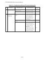
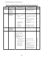
6 Safety Functions When an Abnormality/Error Occurs ........................................ 6-1
6.1
6.2
Safety Functions ................................................................................................................. 6-1
6.1.1 Power Failure ......................................................................................................... 6-1
6.1.2 Abnormal State of Magnetic Bearing ..................................................................... 6-4
6.1.3 Excessive Vibration................................................................................................ 6-5
6.1.4 Inverter Overload ................................................................................................... 6-5
6.1.5 Overheating Inside the STP Pump ........................................................................ 6-5
6.1.6 Overheating Inside the STP Control Unit............................................................... 6-5
6.1.7 Overspeed.............................................................................................................. 6-5
6.1.8 Abnormal Battery Voltage ...................................................................................... 6-6
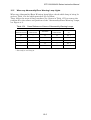
Restarting after Any Safety Function Operates .................................................................. 6-7
7 Baking, Cooling and Gas Suction of the STP Pump .......................................... 7-1
7.1
7.2
7.3
Baking the STP Pump......................................................................................................... 7-1
7.1.1 Attaching a Baking Heater ..................................................................................... 7-2
Cooling the STP Pump........................................................................................................ 7-3
7.2.1 Air Cooling Method................................................................................................. 7-3
Gas Suction......................................................................................................................... 7-4
7.3.1 How to Introduce a Purge Gas (for Chemical Specific Pump Type C).................. 7-4
8 Remote Input/Output Signal Connector.............................................................. 8-1
8.1
8.2
8.3
Remote Input Signals.......................................................................................................... 8-1
Remote Output Signals ....................................................................................................... 8-3
Remote Cables (Optional Accessories).............................................................................. 8-6
9 Internal Battery................................................................................................... 9-1
9.1
9.2
9.3
9.4
9.5
Life of the Internal Battery ................................................................................................... 9-1
Allowable Shelf Life of the Internal Battery ......................................................................... 9-1
How to Charge the Internal Battery..................................................................................... 9-2
How to Replace the Internal Battery ................................................................................... 9-3
9.4.1 How to Replace the Battery Case.......................................................................... 9-4
9.4.2 How to Replace the Battery in the Battery Case ................................................... 9-4
How to Dispose of the Internal Battery ............................................................................... 9-6
10 External Battery................................................................................................ 10-1
10.1
10.2
10.3
10.4
Specifications for the External Battery .............................................................................. 10-2
Installation of the External Battery .................................................................................... 10-3
How to Charge the External Battery ................................................................................. 10-4
How to Dispose of the External Battery ............................................................................ 10-4
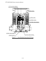
11 Operation Principle of the STP Pump............................................................... 11-1
12 Maintenance and Inspection ............................................................................ 12-1
12.1
12.2
12.3
12.4
12.5
12.6
Replacing the Internal Battery........................................................................................... 12-1
Inspecting the Air Cooling Fan.......................................................................................... 12-1
Replacing the Fuses ......................................................................................................... 12-2
Inspecting for Deposit ....................................................................................................... 12-3
Overhaul............................................................................................................................ 12-4
Transporting for Repair or Overhaul ................................................................................. 12-5
13 Storage............................................................................................................. 13-1
13.1
13.2
13.3
The STP Pump.................................................................................................................. 13-1
The STP Control Unit ........................................................................................................ 13-2
Restarting Precautions...................................................................................................... 13-2
10
STP-200/300/400 Series Instruction Manual
14 Disposal ........................................................................................................... 14-1
14.1
14.2
14.3
The STP Pump.................................................................................................................. 14-1
The STP Control Unit ........................................................................................................ 14-1
The Battery........................................................................................................................ 14-2
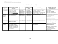
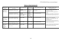
15 Troubleshooting ............................................................................................... 15-1
15.1
15.2
15.3
15.4
15.5
Troubleshooting Immediately after an Abnormality/Error Occurs..................................... 15-1
Abnormalities When Powering ON ................................................................................... 15-2
Abnormalities When Performing the STP Pump Start Operation ..................................... 15-2
Abnormalities While the STP Pump Is Rotating ............................................................... 15-3
When any Abnormality/Error Warning Lamp Lights.......................................................... 15-5
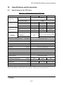
16 Specifications and Accessories ........................................................................ 16-1
16.1
16.2
16.3
16.4
Specifications for the STP Pump ...................................................................................... 16-1
Specifications for the STP Control Unit............................................................................. 16-2
Accessories....................................................................................................................... 16-4
Recommended Spare Parts.............................................................................................. 16-5
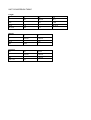
UNIT CONVERSION TABLE
ANNEX
MALFUNCTION INFORMATION
STP Series / Global Service Network
11
STP-200/300/400 Series Instruction Manual
TABLES
Table 3.1
Table 3.2
Table 3.3
Table 4.1
Table 5.1
Table 6.1
Table 6.2
Table 6.3
Table 6.4
Table 8.1
Table 8.2
Table 8.3
Table 8.4
Table 8.5
Table 10.1
Table 15.1
Table 15.2
Table 15.3
Table 15.4
Table 15.5
Table 16.1
Table 16.2
Table 16.3
Table 16.4
Table 16.5
Tightening torque of bolt ................................................................................................. 3-9
Maximum Torque predicted and Recommended securing bolt for inlet port flange..... 3-10
Number of Claw Clamps by Size of Flange.................................................................. 3-11
Connecting the Power Cable ...................................................................................... 4-13
Starting/Stopping the STP Pump during Remote Operation .......................................... 5-7
States of Lamps and REMOTE Output Signals at a Power Failure ............................. 6-2
Operations of the STP Pump after a Power Recovery
(during MANUAL OPERATION) ................................................................................... 6-3
Operations of the STP Pump after a Power Recovery
(during REMOTE OPERATION) ................................................................................... 6-4
Safety Functions ........................................................................................................... 6-8
Remote Input Signals .................................................................................................... 8-1
Remote Output Signals ................................................................................................. 8-3
Rated Contacts for Switch SW1 ................................................................................... 8-5
Rated Contacts for Relays CR5 to 11 ........................................................................... 8-5
Remote Cable Connections (Single-Side Connector Type) ......................................... 8-6
Specifications for the External Battery ........................................................................ 10-2
Troubleshooting after Powering ON ........................................................................... 15-2
Troubleshooting When Performing the STP Pump Start Operation ........................... 15-2
Troubleshooting While the STP Pump Is Rotating ..................................................... 15-3
Cross Reference of Items of Abnormality Warning Lamps ........................................ 15-5
Troubleshooting When any of Abnormality/Error Warning Lamp Lights .................... 15-6
Specifications for the STP Pump ................................................................................ 16-1
Specifications for the STP Control Unit ...................................................................... 16-2
Accessories ................................................................................................................. 16-4
Accessories for Chemical Specific Pump (Type C) .................................................... 16-4
Recommended Spare Parts ....................................................................................... 16-5
12
STP-200/300/400 Series Instruction Manual
FIGURES
Figure 3.1
Figure 3.2
Figure 3.3
Figure 3.4
Figure 3.5
Figure 3.6
Figure 3.7
Figure 3.8
Figure 4.1
Figure 4.2
Figure 4.3
Figure 4.4
Figure 4.5
Figure 4.6
Figure 4.7
Figure 7.1
Figure 8.1
Figure 8.2
Figure 9.1
Figure 9.2
Figure 9.3
Figure 11.1
Figure 16.1
Figure 16.2
Figure 16.3
Figure 16.4
Figure 16.5
Figure 16.6
Configuration of the STP Pump ...................................................................................... 3-2
Installation of the STP Pump to the Vacuum Equipment ............................................... 3-6
STP Pump Installation Positions .................................................................................... 3-8
Positions of the Outlet Port on the Horizontally or Slanted Installed STP Pump ........... 3-8
Example of securing the STP pump (When securing the inlet port with bolts) ............ 3-10
Example of securing the STP pump
(When securing the inlet port flange with claw clamps) ............................................... 3-11
Example of securing the STP pump
(When installing the damper in the inlet port flange) .................................................... 3-12
Connecting the Purge Port ........................................................................................... 3-15
STP Control Unit Front Panel ....................................................................................... 4-2
STP Control Unit Rear Panel ........................................................................................ 4-4
Inside of the STP Control Unit ...................................................................................... 4-6
Peripheral Space of the STP Control Unit .................................................................... 4-8
Example of Securing the STP Control Unit ................................................................... 4-9
External Dimensions of Each Cable ........................................................................... 4-10
How to Secure the Power Cable ................................................................................. 4-14
Attaching Positions of the Cooling Unit and Baking Heater ......................................... 7-5
Remote Input Signal Pins ............................................................................................. 8-2
Remote Output Signal Pins .......................................................................................... 8-4
Life of the Internal ........................................................................................................... 9-2
Allowable Shelf Life of the Internal Battery..................................................................... 9-2
How to Replace the Internal Battery............................................................................... 9-5
Cross Sectional View of the STP Pump ..................................................................... 11-2
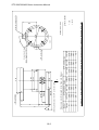
External Appearance of the STP Pump
(without Anti-Corrosion Treatment) (Example: STP-400) ............................................ 16-6
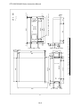
External Appearance of the STP Pump
(Chemical Specific Type C) (Example: STP-400C)...................................................... 16-7
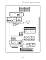
External Appearance of the STP control Unit............................................................... 16-8
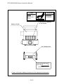
Label Affixing Positions for the STP Pump................................................................... 16-9
Label Affixing Positions for the STP Control Unit ....................................................... 16-10
Label Affixing Positions for the Optional Accessories ................................................ 16-11
13
STP-200/300/400 Series Instruction Manual
1
Precautions for Safe Operation of the STP Pump
1.1
Usable Gases
Chlorine or fluorine system gases can be used in chemical specific pumps
(STP-200C/300C/400C or other models). When you use gases including alkaline
metals, but excluding Li, gases including Ga, Hg, In, or Sn, or HBr, contact BOC
Edwards. Confirm the characteristics of the gas to be used, referring to the
Material Safety Data Sheet (MSDS) you obtain from the gas supplier.
◇
◇
◇
1.2
NEVER use corrosive gases (chlorine, fluorine, or other system
gases) in the STP-200/300/400 pump or other models without
anti-corrosion treatment.
Introduce a dry N2 gas (purge gas) to protect the inside of the STP
pump when using reactive or corrosive gases (See Section 7.3, "Gas
Suction").
Cool the STP pump to prevent the STP pump from overheating when
sucking gases (See Section 7.2, "Cooling the STP Pump").
Maintenance and Inspection Precautions
Read through Section 12, "Maintenance and Inspection" before performing any
maintenance or inspection of the STP pump and the STP control unit (battery
replacement, fuse replacement).
◇
◇
Always turn OFF the primary power (Switch the breaker "OFF")
before performing any maintenance.
NEVER touch any portions other than those designated when
performing maintenance.
Careless touch may cause electric shock and/or a short-circuiting of
the internal circuit, resulting in product damage or a problem.
1-1
STP-200/300/400 Series Instruction Manual
1.3
Labels
The following labels are affixed to the STP pump and STP control unit.
Read the contents of the labels before operation. For the positions of the labels,
see Figures 16. 4 to 16.6.
1) STP Pump Caution Label
This label describes precautions for operating the STP pump.
Follow these precautions.
2) STP Control Unit Caution Label
This label describes precautions for operating the STP control unit.
Follow these precautions.
3) Heavy Product Caution Label
This label is affixed to the product with a weight of 18 kg or more.
Follow the precautions of Section 2, "Unpacking" so as not to cause any
accident during handling.
1-2
STP-200/300/400 Series Instruction Manual
4) STP Pump Installation Warning Label
This label describes installation of the STP pump.
Install the STP pump according to the precautions of Section 3, "Installation
of the STP Pump."
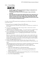
5)
Connector Caution Label
i. This label describes lock of the connector.
ii. This label instructs operators to prevent the connectors from being
disconnected while the STP pump is in operation.
6) STP Control Unit Safety Instruction Label
This label describes instructions before operating the STP control unit.
1-3
STP-200/300/400 Series Instruction Manual
7) High Voltage Device Caution Label
The STP control unit is equipped with a high voltage device.
warns operators to pay attention to the high voltage device.
This label
8) Battery Instruction Label
This label instructs operators to replace batteries once a year.
The next replacement date of batteries is specified upon delivery of the STP
pump.
Record the next replacement date (after one year) of batteries in the blank
of the label when replacing them.
This label describes precautions for use of external batteries.
9) Rotational Direction Instruction Label
This label describes the rotational direction of the STP pump.
The STP pump rotates in this direction.
ROTATION
1-4
STP-200/300/400 Series Instruction Manual
10) Voltage Rating Label
This label describes the rated voltage of the STP control unit.
Use voltage specified in this label.
200V
100V
200 V specification
100 V specification
220V
110V
220 V specification
110 V specification
240V
120V
240 V specification
120 V specification
11) Hot Surface Warning Label
This label instructs operators so as not to touch the hot surface of the STP
pump.
The use of the baking heater (optional accessory) may lead to a considerable
rise in temperatures outside the STP pump.
This label warns operators so as not to burn hands.
(only when using the baking heater.)
1-5
STP-200/300/400 Series Instruction Manual
2
Unpacking
2.1
Unpacking the STP Pump
Check the following before unpacking the STP pump.
1) Check the package for bruises, breakage, wetness, and other.
If there is any abnormality/error or it is judged necessary to return the
product, contact BOC Edwards or the selling agency.
2) Check the contents of the package.
See Section 16.3, "Accessories."
◇
◇
Be careful not to scratch the flange of the STP pump.
Before installing the STP pump, check whether or not there are
scratches on the surface.
It is recommended to keep the packaging materials, such as the
corrugated fiberboard container and cushioning material for possible
reuse.
2-1
STP-200/300/400 Series Instruction Manual
2.2
Unpacking the STP Control Unit
Check the following before unpacking the STP control unit.
1) Check the package for bruises, breakage, wetness, and other.
If there is any abnormality/error or it is judged necessary to return the
product, contact BOC Edwards.
2) Check the contents of the package.
See Section 16.3, "Accessories."
◇
◇
◇
◇
◇
◇
The net mass of the STP control unit is approx. 27 kg. Use a crane
or other appropriate means to lift the STP control unit.
Lift the STP control unit using the two handles attached to the front
panel.
Observe national laws/regulations, safety standards and so on when
lifting the STP control unit.
Use a crane or other appropriate means sufficient enough to
withstand the load when lifting the STP control unit.
Always lift the STP control unit in stable places free of excessive
shock or vibration to prevent it from shaking or dropping.
Have at least two people lift the STP control unit when doing so by
hand.
It is recommended to keep the packaging materials, such as the
corrugated fiberboard container and cushioning material for possible
reuse.
2-2
STP-200/300/400 Series Instruction Manual
3
Installation of the STP pump
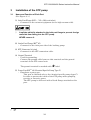
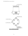
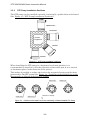
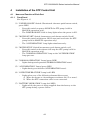
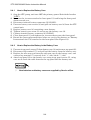
3.1
Name and Function of Each Part
(See Figure 3.1.)
(1) Inlet Port Flange (ICF*1 , VG*2, ISO, and other)
・ Connected to the vacuum equipment (at the high vacuum side).
◇
A splinter shield is attached to the inlet port flange to prevent foreign
materials from falling into the STP pump.
NEVER remove it.
(2) Outlet Port Flange (KF*2 25)
・ Connected to the inlet port side of the backing pump.
(3) STP Connector (41 pins)
・ Connected to the STP connection cable.
(4) Ground Terminal
・ Used for grounding.
Connect the ground cable between this terminal and the ground
terminal of the STP control unit.
The ground terminal is marked with
label.
(5) Purge Port (KF*2 10) (Chemical Specific Pump Type C)
・ Introduces a purge gas.
This port is attached only to the chemical specific pump (type C).
In order to protect the inside of the STP pump when pumping
reactive or corrosive gases.
The STP pump is delivered with a blank flange attached to this
port.
*1:
*2:
JVIS
JIS
3-1
STP-200/300/400 Series Instruction Manual
(1) Inlet Port Flange
(2) Outlet Port Flange
(4) Ground Terminal
(3) STP Connector
(5) Purge Port
Chemical Specific
Type C Only
Figure 3.1
Configuration of the STP Pump
3-2
STP-200/300/400 Series Instruction Manual
3.2
Precautions Before Installation
3.2.1
Operating Environment
◇
◇
Chlorine or fluorine system gases can be used in chemical specific
pumps (type C). When you use gases including alkaline metals, but
excluding Li, gases including Ga, Hg, Sn, or HBr, contact BOC
Edwards.
NEVER use corrosive gases (chlorine, fluorine, or other system
gases) in the STP-200/STP-300/STP-400 pump or other models
without anti-corrosion treatment (See Section 1.1, "Usable Gases").
Install the STP pump in a place meeting the following requirements:
Ambient Temperature
0 to 40 °C
Ambient Relative Humidity 30 to 95 % (no dew condensing)
Environment
STP Pump Installation
Equipment Conditions
• A place free of externally-applied mechanical
shock.
• A place free of a heat source
(Keep clear of the heat source or attach a
thermal shield plate).
• A place free of a strong magnetic field
(Range: up to 150 gauss (15 mT) in the axial
direction, and up to 30 gauss (3 mT) in the
radial direction with respect to the rotational
axis of the STP pump).
• A place free of a strong electric field.
• A place free of exposure to radiation.
• No discharge of high voltage (more than 500 V)
(If more than 500 V is discharged, contact BOC
Edwards).
• Install the STP pump securely so that foreign
materials will easily fall into the STP pump
(Ex.: Si wafers or samples are positioned above
the STP pump)(To prevent foreign materials
from falling into the STP pump, design a shield
plate with large conductance).
3-3
STP-200/300/400 Series Instruction Manual
3.2.2
Installation Area
Leave enough space for the following in addition to that for the STP pump:
•
•
◇
3.2.3
Space for maintenance and inspection
Space for connecting cables
The minimum bending radius of the STP connection cable is
150 mm (See Figures 16.1 and 16.2, "External Appearance of the STP
Pump" [bending dimensions of the STP connection cable]).
DO NOT excessively bend the cables and beware of any obstacles
when installing the STP pump.
Also, leave enough space to install other cables without bending
them excessively.
Bench
A bench must be prepared by the customer to secure the STP pump. The shape
and size of the bench differ depending upon the type of STP pump. Follow the
precautions of the WARNING, CAUTION, or NOTICE (See Section 3.3.3, "How
to Secure the STP Pump").
◇
The STP pump is provided with a high-speed rotor. Any internal
abnormality/error may result in a jump in rotational torque leading to
personal injury or peripheral equipment damage.
Design and secure the bench for the STP pump so that it can
withstand the maximum torque generated due to the occurrence of
an abnormality/error. Refer to Section 3.3.3 "How to Secure the STP
Pump" for abnormal torque.
◇
Secure the customer-prepared bench and the vacuum equipment on
the floor or peripheral equipment and other equipment in accordance
with the customer application. NEVER move them while the STP
pump is in operation.
Use fitting bolts with strength equal to or higher than SUS 304*1.
◇
*1:
JIS
3-4
STP-200/300/400 Series Instruction Manual
◇
*1:
The screw hole for leg for securing the STP pump is M8*1, and the
depth is 16 mm (4 positions).
For the external appearance of the STP pump, see Figures 16.1 and
16.2, "External Appearance of the STP Pump."
JIS
3-5
STP-200/300/400 Series Instruction Manual
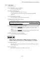
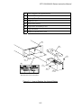
3.3
How to Install the STP Pump
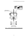
Install the STP pump to the vacuum equipment as shown in Figure 3.2.
The STP pump can be
installed through the damper
(optional accessory)
Vacuum
Equipment
Inlet Port
Inlet Port Flange
Vacuum Valve
To Power Supply
Dry Pump, and other
Power Cable
Auxiliary
Pump
Front STP
Panel Control Unit
STP Connection Cable
Ground Cable
Outlet Port Flange
Remote Cable
To Vacuum Equipmemt Control Circuit
Figure 3.2
◇
◇
◇
◇
◇
Installation of the STP Pump to the Vacuum Equipment
Chlorine or fluorine system gases can be used in chemical specific
pumps (type C). When you use gases including alkaline metals, but
excluding Li, gases including Ga, Hg, In, or Sn, or HBr, contact BOC
Edwards.
NEVER use corrosive gases (chlorine, fluorine, or other system
gases) in the STP-200/STP-300/STP-400 pump or other models
without anti-corrosion treatment (See Section 1.1, "Usable Gases").
When you use the STP pump in a place subjected to exposure to
radiation, contact BOC Edwards.
DO NOT open the STP pump through the flange to atmospheric air
while the STP pump is running.
If atmospheric air flows into the STP pump, it may not function
normally.
Depending upon the type of the backing pump used, atmospheric air
may reverse flow into the STP pump when the backing pump stops.
Attach a vacuum valve to the middle of the piping between the STP
pump outlet port flange and the backing pump, and close the vacuum
valve when the backing pump stops.
3-6
STP-200/300/400 Series Instruction Manual
◇
◇
◇
3.3.1
The STP pump cannot be used with the outlet port open to
atmospheric air.
Always use the backing pump (dry pump or similar one).
Use a backing pump with a pumping speed of 160 L/min or more for
the STP-200 series, or 240 L/min or more for the STP-300/400 series.
Depending upon the type of the backing pump used, oil vapor may
contaminate the inside of the STP pump. Some oil viscosity could
cause a malfunction when there is a strong reverse flow of oil.
Take the following measures to ensure the correct flow of oil:
• Attach a vacuum valve to the middle of the piping between the STP
pump outlet port flange and the backing pump.
• Attach an absorption trap adjacent to the vacuum valve.
Cleaning the Seal
Inspect the seals of inlet and outlet port flanges for dirt or oil spots before
installing the STP pump in the vacuum equipment.
Take the following measures for cleaning the seals:
•
•
Clean off with a pure gas.
Wipe with proper solvent (such as alcohol).
◇
A splinter shield is attached to the inlet port flange to prevent foreign
materials from falling into the STP pump.
Always leave the splinter shield attached during operation.
◇
The splinter shield cannot perfectly prevent foreign materials from
falling into the STP pump.
DO NOT install the STP pump in such a manner that foreign materials
can easily fall into it (for example, Si wafers or samples are
positioned above the STP pump). If installing the STP pump in such
a manner, always attach a shield plate with sufficient conductance
above the STP pump to prevent foreign materials from falling into it.
Foreign materials falling into the STP pump through the splinter
shield may result in product damage.
Be careful not to scratch the flange of the STP pump.
Check whether or not there are scratches on the surface, before
installing the STP pump.
◇
3-7
STP-200/300/400 Series Instruction Manual
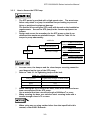
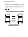
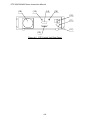
3.3.2
STP Pump Installation Positions
The STP pump can be installed vertically, horizontally, upside-down and slanted
(See Figure 3.3, "STP Pump Installation Positions").
Upside-down
Horizontal
Vacuum
Equipment
Slanted
Vertical
Figure 3.3
STP Pump Installation Positions
When installing the STP pump in a horizontal or slanted position, it is
recommended to install it so that the direction of the outlet port is on a vertical
or horizontal plane in the direction of the gravity.
This makes it possible to reduce the load on the magnetic bearing and the heat
generated by the STP pump (See Figure 3.4, "Positions of the Outlet Port on the
Horizontally or Slanted Installed STP Pump").
Outlet Port
Outlet Port
Figure 3.4
Outlet Port
Outlet Port
Direction of Gravity
Positions of the Outlet Port on the Horizontally or Slanted Installed STP Pump
3-8
STP-200/300/400 Series Instruction Manual
3.3.3
How to Secure the STP Pump
◇
◇
The STP pump is provided with a high-speed rotor. The worst-case
failure may result in a jump in rotational torque leading to personal
injury or peripheral equipment damage.
The method of securing the STP pump will depend on the installation
requirements. Secure the STP pump to the vacuum equipment as
follows:
Design and secure the mounting for the STP pump so that it can
withstand the maximum rotational torque. Refer to Table 3.2 for
torque in pump abnormality.
with bolts
Refer to “1) When securing the
No
Secure the inlet port
inlet port with bolts”
Refer to “2) When securing the
Damper
with Claw Clamps
inlet port flange with claw
clamps”
Refer to “3) When installing the
Yes
◇
◇
damper in the inlet port flange”
In some cases, the damper and the claw clamper securing cannot be
used depend on the type of the STP pump.
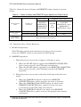
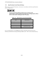
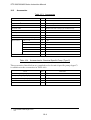
Refer to Table 3.1 for tightening torque of the bolt.
Table 3.1
◇
◇
◇
Tightening torque of bolt
Size of bolt
Tightening torque of bolt (Nm)
M8
12.0
M10
24.1
M12
42.1
When making the leg to secure the base, make them shortened more
than ones attached to the STP pump.
Use a material that has a tensile strength of 600N/mm2 or more.
When securing the base, use stainless steel securing bolts with a
tensile strength class is 70 or more.
When using any securing method other than that specified in this
manual, contact BOC Edwards.
3-9
STP-200/300/400 Series Instruction Manual
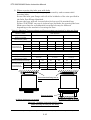
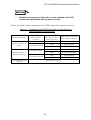
1) When securing the inlet port with bolts
Refer to Table 3.2 for torque in pump abnormality and recommended
securing bolts.
Secure the inlet port flange with all of the boltholes of the size specified in
the Inlet Port Flange Standard.
Secure the base with all 8 screw-holes for legs or all 8 attached legs.
Follow "CAUTION" on page 3-9 about legs and bolts for securing the base.
Make sure that the recommended securing bolt may be different
depending on the method of securing the base.
Table 3.2 Maximum Torque predicted and Recommended securing bolt for inlet port flange
Model of TMP
STP-200/300
Type of flange
Torque in pump
abnormality [Nm]
Base(8 positions)securing
Recommended
securing bolt
for TMP Flange
Type of bolt
Type of
steel*1
Strength*1
VG100
ISO100F/ISO100
ICF152
3.4×10³
3.4×10³
3.4×10³
No
Yes
No
Yes
No
Yes
Standard
Standard
Standard
Standard
Standard
Standard
Stainless steel Stainless steel Stainless steel Stainless steel Stainless steel Stainless steel
70 or more
70 or more
70 or more
Model of TMP
Base(8 positions)securing
Type of bolt
Type of
70 or more
70 or more
STP-400
Type of flange
Torque in pump
abnormality [Nm]
Recommended
securing bolt
for TMP Flange
70 or more
steel*1
Strength*1
VG125/VG150
ISO160F/ISO160
ICF203
3.4×10³
3.4×10³
3.4×10³
No
Yes
No
Yes
No
Yes
Standard
Standard
Standard
Standard
Standard
Standard
Stainless steel Stainless steel Stainless steel Stainless steel Stainless steel Stainless steel
70 or more
70 or more
70 or more
70 or more
70 or more
70 or more
Recommended fitting bolt for
flange
Secure the base
(a) When the base is not secured
(b) When the base is secured
Figure 3.5 Example of securing the STP pump
(When securing the inlet port with bolts)
*1 Refer to ISO898-1(JISB1051), ISO3506(JISB1054) and AMS6419(Aerospace Material Specification)
3-10
STP-200/300/400 Series Instruction Manual
2) When securing the inlet port flange with claw clamps
Refer to Table 3.2 for rotational torque.
When securing the inlet port flange with only the claw clamp, the vacuum
equipment cannot withstand the maximum rotational torque generated
by the worst-case failure. To make the vacuum equipment withstand
abnormal torque, secure the base with all 8 screw-holes for legs or all 8
attached legs. Follow "CAUTION" on page 3-9 about legs and bolts for
securing the base.
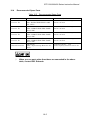
For the claw clamp-type, use the required number of claw clamps as
specified in Table 3.3. Position the claw clamps evenly on the
circumference.
Table 3.3
Number of Claw Clamps by Size of Flange
Size of Flange
ISO 160 or less
ISO 200 to 250
ISO 320 or more
Number of Claw Clamps
4 or more
6 or more
8 or more
Vacuum Equipment
Claw Clamps
Secure the base
Figure 3.6 Example of securing the STP pump
(When securing the inlet port flange with claw clamps)
3-11
STP-200/300/400 Series Instruction Manual
3) When installing the damper in the inlet port flange
Refer to Table 3.2 for rotational torque.
In case of using a damper, secure the base with all 8 screw-holes for legs
or all 8 attached legs. Follow "CAUTION" on page 3-9 about legs and
bolts for securing the base.
When the base cannot be secured because of the equipment design, install
the pump with a torque restraint like the one shown in Figure 3.7 (b).
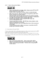
◇
◇
Use a damper only at the vertically upright position.
DO NOT remove the bolts and nuts attached to reinforce the damper.
Vacuum Equipment
Vacuum Equipment
Damper Clamps
Secure the base
Hole to prevent
from rotating
Leg
(a) When securing the base
(b) When installing not to rotate
Figure 3.7 Example of securing the STP pump
(When installing the damper in the inlet port flange)
3-12
STP-200/300/400 Series Instruction Manual
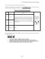
3.3.4
Vacuum Piping
◇
◇
DO NOT open the STP pump through the flange to atmospheric air
while the STP pump is running.
If atmospheric air flows into the STP pump, it may not function
normally.
Depending upon the type of the backing pump used, atmospheric air
may reverse flow into the STP pump when the backing pump stops.
Attach a vacuum valve to the middle of the piping between the STP
pump outlet port flange and the backing pump, and close the vacuum
valve when the backing pump stops.
In order to let the STP pump bring its performance into full play, follow the
precautions below:
1) Be careful not to scratch the flange of the STP pump.
Before installing the STP pump, check whether or not there are scratches on
the surface.
2) Use steel or aluminum tubes with a low gas loss to connect the vacuum
equipment to the STP pump.
3) Take measures for minimizing leakage. It is also necessary to degrease the
tubes as regularly as possible to keep the gas loss as low as possible.
4) It is recommended to use a backing pump of pumping speed 160 L/min or
more for the STP-200 series, or pumping speed 240 L/min or more for the
STP-300/400 series.
However, the pressure at the inlet and outlet ports varies with the flow rate
of gas, capacity of the vacuum equipment, length and material of the piping.
Select a backing pump in accordance with the capacity and starting method
(simultaneous starting, starting after generating roughing vacuum) suitable
for the vacuum equipment you use.
5) Connect the STP pump and the backing pump using stainless steel or
aluminum alloy tubing, flexible tubing, vacuum rubber or Teflon tubing, and
other.
The following measures can be used to avoid the transmission of the vibration
of the backing pump to the STP pump and the vacuum equipment.
• DO NOT place the backing pump on the same floor as the vacuum
equipment.
• Locate the backing pump on a vibration-proof table.
Attain 1/3 or less of the rotational speed of the backing pump, when
adjusting the inherent frequency of the backing pump installed on a
vibration-proof table.
• Attach a weight to the piping from the backing pump, or secure the piping
to a rigid, heavy object free of vibration.
• Use a tube of high flexibility.
3-13
STP-200/300/400 Series Instruction Manual
6) Depending upon the type of the backing pump used, oil vapor may
contaminate the inside of the STP pump. Some oil viscosity could cause a
malfunction when there is a strong reverse flow of oil.
Take the following measures to ensure the correct flow of oil:
• Attach a vacuum valve to the middle of the piping between the STP pump
outlet port flange and the backing pump.
• Attach an absorption trap adjacent to the vacuum valve.
Piping at the Inlet Port Flange
Attach the inlet port to the high vacuum side.
Maximum working pressure:
Pressure at the inlet port flange
applicable continuously
1.3×10⁻² Pa [1×10⁻⁴ Torr]
(for natural air cooled)
Piping at the Outlet Port Flange
Attach the outlet port to the inlet port flange of the backing pump
(primary side pump).
Allowable backing pressure:
Pressure at the outlet port flange
applicable continuously
◇
13 Pa [0.1 Torr]
(for natural air cooled)
To attain the ultimate pressure shown in Table 16.1,”Specifications
for the STP Pump,” set the pressure at the outlet port flange to
1.3 Pa (10-2 Torr) or less.
3-14
STP-200/300/400 Series Instruction Manual
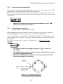
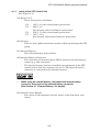
3.3.5
Connecting the Ground Cable
Connect the ground cable (yellow/green) between the ground terminal of the STP
pump and the ground terminal of the STP control unit.
When the resistance between the ground terminals is lower than 0.1 Ω, it is not
necessary to connect the ground cable after installing the STP pump and the STP
control unit.
◇
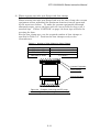
3.3.6
When the resistance between the ground terminals is over 0.1 Ω,
always connect the ground cable.
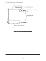
Connecting the Purge Port
(For the chemical specific pump type C)
When pumping reactive or corrosive gases, introduce a dry N2 gas or other gas
into the STP pump in order to protect the inside of the STP pump.
As shown in Figure 3.8, introduce a dry N2 gas through the electromagnetic vent.
valve, needle valve or similar valve (must be prepared by the customer) from the
purge port.
For instructions on how to introduce the purge gas, see Section 7.3, "Gas
Suction."
◇
◇
◇
The proper amount of gas purge is approx. 1.7×10⁻² Pa·m3/sec.
(10 SCCM).
The allowable gas pressure ranges from zero (atmospheric pressure)
to 0.5 kgf/cm2 (gauge pressure).
When not introducing the purge gas, close the purge port with the
blank flange (attached at delivery).
KF10
Dry N2Gas or Other
Purge Port
Figure 3.8
Connecting the Purge Port
3-15
STP-200/300/400 Series Instruction Manual
4
Installation of the STP Control Unit
4.1
Name and Function of Each Part
4.1.1
Front Panel
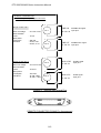
(See Figure 4.1.)
(1) "POWER ON/OFF" Switch (illuminated alternate push button switch,
green LED)
・ Press this switch to power ON/OFF the STP pump (valid in
MANUAL operation only).
・ The POWER ON/OFF built-in lamp lights when the power is ON.
(2) "MOTOR START" Switch (momentary push button switch, black)
・ Press this switch with power ON to start and accelerate the STP
pump (valid in MANUAL operation only).
・ The "ACCELERATION" lamp lights simultaneously.
(3) "MOTOR STOP" Switch (momentary push button switch, red)
・ Press this switch to decelerate and stop the STP pump (valid in
MANUAL operation only).
・ The "NORMAL OPERATION" lamp or the "ACCELERATION"
lamp goes out.
(4) "NORMAL OPERATION" Lamp (green LED)
・ Lights during rated operation (NORMAL OPERATION state).
(5) "ACCELERATION" Lamp (green LED)
・ Lights during acceleration (ACCELERATION state).
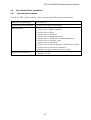
(6) "OVER TEMPERATURE" Lamp (red LED)
・ Lights when any of the following abnormalities occurs:
a) When the motor or electromagnet overheats (90 °C or more).
b) When the STP connection cable is not connected.
(7) "BATTERY OPERATION" Lamp (red LED)
・ Lights while the power is being supplied from the battery to the
STP pump during a power failure.
4-1
STP-200/300/400 Series Instruction Manual
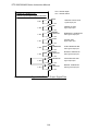
(8) "FAILURE" Lamp (red LED)
・ Lights when any of the following abnormalities occurs:
a) When the inside of the STP control unit overheats (75 °C or
more inside the heat sink).
b) When the motor or electromagnet overheats (100 °C or more).
c) When an abnormality occurs inside the inverter (overload,
overspeed).
d) When the battery is thoroughly worn out and cannot be
charged.
e) When the STP connection cable is not connected.
(9) "EMERGENCY OPERATION" Lamp (red LED)
・ Lights when any of the following abnormalities occurs:
a) When a power failure occurs.
b) When continuous vibration impact is applied to the rotor
causing it to come into contact with the touch down bearing.
c) When the STP connection cable is not connected.
For details concerning lamps (6) to (9) and abnormalities, see Section 6,
"Safety Functions When an Abnormality/Error Occurs" and Section 15,
"Troubleshooting."
(10) ROTATION Meter (tachometer)
・ Indicates the number of rotations (rpm).
・ The needle moves to the black with an increase in rpm.
・ The needle moves to the red with a decrease in rpm.
・ The needle is located in the black during the rated operation.
(10)
(4)
(5)
(6)
(7)
(8)
(9)
(1)
(3)
(2)
Figure 4.1 STP Control Unit Front Panel
4-2
STP-200/300/400 Series Instruction Manual
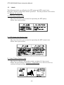
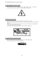
4.1.2
Rear Panel
(See Figure 4.2.)
(11) AC POWER Connector (CON30)
・ For primary power input.
(12) MAIN POWER Breaker
・ Switches ON/OFF the primary power.
・ A metal fitting is attached to secure the breaker at the OFF
position.
(13) P. CONNECTOR (CON20)
・ For connection of the STP connection cable.
(14) REMOTE CONNECTOR (CON40)
・ For remote control.
For details of the REMOTE CONNECTOR (14), see Section 8, “Remote
Input/Output Signal Connector.”
(15) "MANUAL/REMOTE" Changeover Switch
・ When setting to MANUAL, only start, stop or other operations can
be performed with the switches on the STP control unit front
panel.
・ When setting to REMOTE, only start, stop or other operations can
be performed by inputting the remote signal.
(16) EXT. BATTERY Connector (CON90)
・ For connection of an external battery.
◇
When using an external battery, always disconnect the internal
battery connector (See Section 10, "External Battery" for details).
(17) Ground Terminal
・ For connection of the ground cable between the STP pump and the
STP control unit.
(18) Air Cooling Fan
・ For cooling the inside of the STP control unit.
4-3
STP-200/300/400 Series Instruction Manual
(18)
(14)
(15)
(16)
(12)
(11)
(17)
(13)
Figure 4.2 STP Control Unit Rear Panel
4-4
STP-200/300/400 Series Instruction Manual
4.1.3
Inside of the STP Control Unit
(See Figure 4.3.)
(19) Fuses 2 to 5
・ These fuses protect as follows:
F2
F3
F4
F5
: 125 V, 8 A (for control power protection)
: 250 V, 3 A
(for inverter and air cooling fan protection)
: 250 V, 5 A (for control power protection)
: 125 V, 10 A
(for internal and external batteries protection)
(20) Inverter
・ This is a three-phase transistor-inverter which starts/stops the STP
pump.
(21) Internal Battery
・ For backup during a power failure.
(22) Internal Battery Connector
・ For connection of internal battery (When using an internal battery,
connect it to this connector).
・ The internal battery has been installed upon shipment of the STP
control unit so that the customer can use it (The internal battery
connector is connected to the internal battery).
◇
When using an external battery, disconnect the internal battery
connector, then connect the external battery connector
(See Section 10, "External Battery" for details).
(23) Control Circuit Boards
・ For control of the magnetic bearing, motor, safety functions, and
others.
4-5
STP-200/300/400 Series Instruction Manual
(19)
(20)
(21)
(22)
Figure 4.3 Inside of the STP Control Unit
4-6
(23)
STP-200/300/400 Series Instruction Manual
4.2
4.2.1
Precautions Before Installation
Operating Environment
Install the STP control unit in a place meeting the following requirements:
Ambient Temperature
0 °C to 40 °C
Ambient Relative Humidity
30 to 95% (no dew condensing)
Environment
•
•
•
•
•
•
•
•
•
•
•
•
Installation Condition
A place free of exposure to direct sunlight.
A place free of high humidity.
A place free of dust.
A place free of salty air.
A place free of dripping water.
A place free of explosive or inflammable gas.
A place free of corrosive gas.
A place free of radiation.
A place free of strong magnetic and electric fields.
A place free of excessive vibration.
A place free of a source of electric noise.
Install the STP control unit horizontally
(within ±10°C).
4-7
STP-200/300/400 Series Instruction Manual
4.2.2
Installation Area
Leave enough space for the following in addition to that for the STP control unit
(See Figure 4.4, "Peripheral Space of the STP Control Unit.")
◇
The minimum bending radius of the STP connection cable is
150 mm (See Figure 16.3, "External Appearance of the STP Control
Unit" [Cable Space]).
DO NOT excessively bend the cables and beware of any obstacles
when installing the STP pump.
Also, leave enough space to install other cables without bending
them excessively.
Rack Wall Side
5cm or more
5cm or more
5cm or more
•
Space for maintenance and inspection
Space for inlet and outlet of air for cooling
- Top and side: 5 cm or more
- Bottom:
1.8 cm or more (height of the rubber foot)
Space for connecting the cables
- Rear:
15 cm or more
1.8cm or more
•
•
Rack Wall Side
5cm or more
15cm or more
Figure 4.4 Peripheral Space of the STP Control Unit
4-8
STP-200/300/400 Series Instruction Manual
4.3
Attaching the STP Control Unit to a Rack
The dimensions of the STP control unit front panel conform to EIA standard.
Therefore, this panel can be attached to any type of commercially-available racks.
Attach the STP control unit to the rack according to the following steps:
1) When attaching the STP control unit to a rack:
• Attach the front panel to a rack using the screw holes for the front panel.
• Also support the STP control unit from the bottom using a support angle
or a similar tool.
2) When attaching the STP control unit to a movable rack:
• Attach the front panel to a movable rack using the screw holes for the
front panel.
• To protect the STP control unit during transport, remove the rubber foot
from the bottom and attach the STP control unit to the rack using the
screw holes for the rubber foot.
◇
◇
◇
The STP control unit cannot be supported with only the screws on
the front panel (The STP control unit is a heavy product).
Always support it from the bottom. DO NOT block the ventilation port.
For the peripheral space of the STP control unit, see Figure 4.4,
"Peripheral Space of the STP Control Unit."
For the dimensions of the front panel and positions of screw holes
for the rubber foot, see Figure 16.3, "External Appearance of the STP
Control Unit."
part: Secure with screw
Support Angle
Figure 4.5 Example of Securing the STP Control Unit
4-9
STP-200/300/400 Series Instruction Manual
4.4
Cable Connection
4.4.1
Name and Dimensions of Each Cable
(unit : mm)
STP Pump Side
STP Control Unit Side
Ground Terminal ( ・ )
Ground Cable
Crimp-Type Terminal Lug
Crimp-Type Terminal Lug (M4 * 1 )
Yellow/Green Wire
L≦20m:4mm2
L>20m:10mm2
64
φ4.3 (L≦20m)
φ6.5 (L>20m)
41 Pin (receptacle)
STP-200/300/400
Series
24.5
φ39
φ14
34 Pin (plug)
72.5
STP Connection Cable
Ground Terminal ( ・ )
(M4 *1 )
62.5
3 Pin (receptacle)
Crimp-Type Terminal Lug (M4 * 1 )
φ 8.1
28
18
20
Power Cable
55
1.5mm2×3 cores (brown, blue, yellow/green)
*1
Figure 4.6 External Dimensions of Each Cable
*1 : JIS
4-10
STP-200/300/400 Series Instruction Manual
4.4.2
How to Connect the Cables
◇
◇
◇
◇
◇
When connecting/disconnecting cables, always power OFF the STP
pump (Switch the breaker "OFF").
Failure to do so may result in electric shock or product damage.
With each connector, align the position of the guide key and insert
the pin vertically so as not to bend it.
If the pin is bent, not only may the connector not function normally,
but may make the pins contact each other, resulting in a malfunction.
Lock and securely tighten each connector and screw.
DO NOT apply voltage to each pin and DO NOT cause any
short-circuiting between pins.
Connect each cable securely. DO NOT place heavy objects on the
cables nor bend them excessively.
Support each cable so as not to apply direct force to the connectors
or terminals.
If any problem occurs in cables, connectors or terminals, the STP
pump may not function normally.
1) Connecting the Ground Cable
Connect the ground cable (yellow/green) between the ground terminal of the STP
pump and the ground terminal of the STP control unit.
When the resistance between the ground terminals is lower than 0.1 Ω, it is not
necessary to connect the ground cable after installing the STP pump and the STP
control unit.
◇
◇
First, connect the ground cable. Next, connect other cables.
When the resistance between the ground terminals is over 0.1 Ω,
always connect the ground cable. Failure to do so may result in
electric shock.
4-11
STP-200/300/400 Series Instruction Manual
2) Connecting the STP Connection Cable
Connect the receptacle side of the STP connection cable to the STP connector of
the STP pump and connect the plug side to "P.CONNECTOR CON20" of the STP
control unit.
◇
◇
Always use the STP pump, STP control unit and the STP connection
cables of the same model name, serial number and cable length.
Failure to do so may result in product damage.
Contact your nearest BOC Edwards representative if you plan to use
units with the same model name but different serial numbers and
cable length; They must be adjusted. In some cases, the
configuration may need more adjustment.
Use the STP connection cable that has a label affixed
STP-200/300/400
Series
The use of different cables may result in product damage.
4-12
STP-200/300/400 Series Instruction Manual
3) Connecting the Power (Primary Side) Cable
Connect the primary power cable to the "AC POWER CON30" on the STP control
unit rear panel as shown in Table 4.1.
Table 4.1 Connecting the Power Cable
CON30
Pin No.
Cable Color
1 (L)
Brown
2 (N)
Blue
Remarks
Single phase 200 V AC ±10% (for 200 V specification)
Single phase 220 V AC ±10% (for 220 V specification)
Single phase 240 V AC ±10% (for 240 V specification)
Single phase 100 V AC ±10% (for 100 V specification)
Single phase 110 V AC ±10% (for 110 V specification)
Single phase 120 V AC ±10% (for 120 V specification)
Both 50/60 Hz
Rear Panel
"AC POWER"
Outline of
connector
N PE L
3 (PE)
Yellow/Green Ground
Secure the power cable to the STP control unit rear panel using the cable fitting
tool (See Figure 4.7).
◇
◇
◇
◇
Confirm the power voltage on the name plate.
Connect the power cable securely to prevent incorrect wiring.
DO NOT apply surge voltage exceeding 1 kV to the input power line.
Always ground power cable to prevent electric shock.
4-13
STP-200/300/400 Series Instruction Manual
STP Control Unit (Top View)
AC POWER CON30
Power Cable Connector
Secure with two screws (M3*1)
Cable Fitting Tool
STP Control Unit (Right Side)
*1
Figure 4.7 How to Secure the Power Cable
*1 :
JIS
4-14
STP-200/300/400 Series Instruction Manual
5
How to Start/Stop the STP Pump
◇
◇
◇
5.1
NEVER connect or disconnect any cables while the power is ON.
NEVER turn the primary power OFF (Switch the breaker "OFF") while
the STP pump is in rotation.
DO NOT release the inlet port flange or outlet port flange into the
atmosphere while the STP pump is in rotation.
Before Starting
After completing installation, piping, leakage test of the STP pump, installation
of the STP control unit, and wiring, the STP pump is ready for start.
Check the following items before starting:
1) Are the STP pump and the STP control unit secured according to the
appropriate method?
2) Is the primary power cable connected correctly to the power supply?
3) Is the power voltage selected properly?
4) Do the serial number and the cable length of the STP pump, the STP control
unit and the STP connection cable match?
5) Is the label affixed correctly to the STP connection cable?
STP-200/300/400
Series
6) Are the ground cable and the STP connection cable securely connected?
Are each terminal and each connector securely locked?
5.2
Starting/Stopping Time
Starting time: Approx. 10 minutes after start operation.
Stopping time: Approx. 15 minutes after stop operation.
If the rotational speed does not attain the rated speed within approx. 30 minutes,
the "FAILURE" lamp lights. Before restarting the STP pump, always check
whether or not there is leakage from the piping or the vacuum equipment and
also confirm the capacity and the START state of the backing pump.
◇
When start/stop operations are frequently performed, the STP pump
may overheat. Avoid doing so.
5-1
STP-200/300/400 Series Instruction Manual
5.3
Start Procedures
Start the backing pump before or simultaneously with start of the STP pump.
Open the vacuum valve located at the outlet port flange side after starting the
backing pump.
◇
5.4
DO NOT open the vacuum valve without operating the backing pump.
Depending upon the type of the backing pump, doing so may cause a
reverse flow of oil, which could contaminate the inside of the STP
pump.
Stop Procedures
Close the vacuum valve located at the outlet port flange side just before or after
stopping the STP pump.
After closing the valve, stop the backing pump.
◇
DO NOT stop the backing pump without closing the vacuum valve.
Depending upon the type of the backing pump, doing so could cause
a reverse flow of atmospheric air into the STP pump, which may
result in a malfunction.
◇
DO NOT stop the backing pump without closing the valve.
Depending upon the type of the backing pump, doing so may cause a
reverse flow of oil, which could contaminate the inside of the STP
pump.
5-2
STP-200/300/400 Series Instruction Manual
There are two methods of operating the STP pump: MANUAL and
REMOTE.
Select one which fits your vacuum equipment.
5.5
Manual Operation
Slide the "MANUAL/REMOTE" changeover switch on the rear panel to "MANUAL."
5.5.1
Powering ON
1) Switch "ON" the breaker on the rear panel.
(A metal fitting is attached to the breaker to lock the breaker at the "OFF"
position. Loosen the screw, lower the metal fitting, switch "ON" the breaker,
then tighten the screw.)
2) Press the "POWER ON/OFF" switch (The switch is thoroughly locked down).
The magnetic bearing functions and the rotor levitates.
The "POWER ON/OFF" switch built-in lamp lights (POWER ON state).
◇
5.5.2
Although the POWER ON operation may cause an "Abnormality/Error
Warning" lamp to light and an alarm signal to be output from the
REMOTE CONNECTOR, this is not an indication of abnormality.
This state is released within 5 seconds.
Starting the STP Pump
1) Press the "MOTOR START" switch on the front panel after powering "ON" to
start the STP pump.
The STP pump starts to accelerates.
The "ACCELERATION" lamp lights (ACCELERATION state).
2) When the STP pump attains the rated speed of rotations, the
"ACCELERATION" lamp goes out, and the "NORMAL OPERATION" lamp
lights (NORMAL OPERATION state).
5-3
STP-200/300/400 Series Instruction Manual
5.5.3
Stopping the STP Pump
1) Press the "MOTOR STOP" switch on the front panel to stop the STP pump.
The STP pump starts to decelerate and stops.
The "NORMAL OPERATION" lamp or the "ACCELERATION" lamp goes out
(BRAKE state).
2) The number of rotations goes down to approx. 3,000 rpm or less in approx.
15 minutes. This decrease in rpm is indicated by the ROTATION meter on
the front panel showing a full-scale deflection to the red.
◇
◇
◇
5.5.4
Make sure the STP pump stops thoroughly by confirming that the
ROTATION meter on the front panel deflects to full-scale in the red.
When the pressure inside the STP pump is 1.3×10⁻⁵ Pa [10-7 Torr] or
less, the stopping time is 15 minutes or more.
The STP pump can be stopped faster by introducing a gas (such as
dry N2 gas) into the STP pump. Introduce a gas so that the pressure
inside the STP pump increases to 5.3×10² to 6.7×10² Pa [4 to 5 Torr]
in 10 seconds after gas introduction.
Note that a sharp increase in the pressure may cause the STP pump
to operate abnormally.
Starting the STP Pump after Stopping
Press the "MOTOR START" switch on the front panel to reaccelerate the STP
pump.
The STP pump can be reaccelerated even while it is stopping.
5-4
STP-200/300/400 Series Instruction Manual
5.5.5
Powering OFF
1) When both the "ACCELERATION" and "NORMAL OPERATION" lamps are
off and the ROTATION meter shows a full-scale deflection to the red:
i.
Press the "POWER ON/OFF" switch. The switch pops up into the
unlocked position, the magnetic bearing stops, and the rotor lands
(POWER OFF state).
The "POWER ON/OFF" switch built-in lamp goes out.
ii. Switch "OFF" the breaker on the rear panel.
2) When either of the "ACCELERATION" and "NORMAL OPERATION" lamps
is lit or the ROTATION meter does not show a full-scale deflection to the red:
i.
Even by pressing the "POWER ON/OFF" switch to switch it "OFF," the
rotor does not land, the pump's operation state remains unchanged, and
the "POWER ON/OFF" switch built-in lamp remains lit.
When the number of rotations goes down to approx. 3,000 rpm or less,
the magnetic bearing stops, the rotor lands, and the "POWER ON/OFF"
switch built-in lamp goes out.
ii. Switch "OFF" the breaker on the rear panel.
◇
◇
The brake of the STP pump disengages at approx. 3,000 rpm, after
which the STP pump still rotates by inertia.
Powering OFF immediately after pressing the "MOTOR STOP" switch
or while either of the "ACCELERATION" and "NORMAL OPERATION"
lamps is being lit causes the touch down bearing to touch the rotor
resulting in a noise when the brake disengages. Although this is
not an indication of abnormality, repetitions of such an operation will
expedite the wear of the touch down bearing.
Such operations will expedite the wear of the touch down bearing.
It is recommended to power "OFF" the STP pump after it stops
thoroughly.
Although the POWER OFF operations may cause an
"Abnormality/Error Warning" lamp to light and an alarm signal to be
output from the REMOTE CONNECTOR, this is not an indication of
abnormality.
This state is released within 5 seconds.
5-5
STP-200/300/400 Series Instruction Manual
5.6
Remote Operation
(Read through Section 8, "Remote Input/Output Signal Connector"
before use.)
Slide the "MANUAL/REMOTE" changeover switch on the rear panel to
"REMOTE."
5.6.1
Powering ON
1) Switch "ON" the breaker on the rear panel.
(A metal fitting is attached to the breaker to lock the breaker at the "OFF"
position. Loosen the screw, lower the metal fitting, switch "ON" the breaker,
then tighten the screw.)
2) Input 24 V DC between (1)-(13) (POWER ON) of the REMOTE CONNECTOR
(CON40) for 0.3 seconds or more ((1): "+" side; (13): "-" side).
The magnetic bearing functions, and the rotor levitates.
The "POWER ON/OFF" switch built-in lamp lights (POWER ON state).
◇
Although the POWER ON operation may cause an "Abnormality/Error
Warning" lamp to light and an alarm signal to be output from the
REMOTE CONNECTOR, this is not an indication of abnormality.
This state is released within 5 seconds.
5-6
STP-200/300/400 Series Instruction Manual
5.6.2
Starting/Stopping the STP Pump
Table 5.1 describes how to start or stop the STP pump during remote operation.
Table 5.1 Starting/Stopping the STP Pump during Remote Operation
Connector
Remote
Connector
(CON40)
◇
◇
◇
5.6.3
Starting the Pump
Input 24 V DC between (3)-(15) (MOTOR
START) for 0.3 seconds or more ((3): "+"
side; (15): "-" side).
However, when inputting this START
signal simultaneously with inputting the
POWER ON signal, input this signal for
5 seconds or more.
Stopping the Pump
Input 24 V DC between
(4)-(16) (MOTOR STOP) for
0.3 seconds or more ((4): "+"
side; (16): "-" side).
The STOP signal has priority
over the START signal.
Make sure the STP pump stops thoroughly by confirming that the
ROTATION meter on the front panel deflects to full-scale in the red.
When the pressure inside the STP pump is 1.3×10⁻⁵ Pa [10-7 Torr] or
less, the stopping time is 15 minutes or more.
The STP pump can be stopped faster by introducing a gas (such as
dry N2 gas) into the STP pump. Introduce a gas so that the pressure
inside the STP pump increases to 5.3×10² to 6.7×10² Pa [4 to 5 Torr]
in 10 seconds after gas introduction.
Note that a sharp increase in the pressure may cause the STP pump
to operate abnormally.
Starting the STP Pump after Stopping
Perform the start operation to reaccelerate the STP pump. See Section 5.6.2,
"Starting/Stopping the STP Pump."
The STP pump can be reaccelerated even while it is stopping.
5-7
STP-200/300/400 Series Instruction Manual
5.6.4
Powering OFF
The POWER OFF signal has priority over the START signal.
1) When both the "ACCELERATION" and "NORMAL OPERATION" lamps are
off and the ROTATION meter shows a full-scale deflection to the red:
i.
Input 24 V DC between (2)-(14) (POWER OFF) of the REMOTE
CONNECTOR (CON40) for 0.3 seconds or more ((2): "+" side; (14): "-"
side). The magnetic bearing stops, and the rotor lands (POWER OFF
state).
The "POWER ON/OFF" switch built-in lamp goes out.
ii. Switch "OFF" the breaker on the rear panel.
2) When either of the "ACCELERATION" and "NORMAL OPERATION" lamps
is lit or the ROTATION meter does not show a full-scale deflection to the red:
i.
Even by inputting the POWER OFF signal from the REMOTE
CONNECTOR in the same way as 1), the rotor does not land, the pump's
operation state remains unchanged, and the "POWER ON/OFF" switch
built-in lamp remains lit.
When the number of rotations goes down to approx. 3,000 rpm or less,
the magnetic bearing stops, the rotor lands, and the "POWER ON/OFF"
switch built-in lamp goes out.
ii. Switch "OFF" the breaker on the rear panel.
◇
◇
The brake of the STP pump disengages at approx. 3,000 rpm, after
which the STP pump still rotates by inertia.
Powering OFF immediately after pressing the "MOTOR STOP" switch
or while either of the "ACCELERATION" and "NORMAL OPERATION"
lamps is being lit causes the touch down bearing to touch the rotor
resulting in a noise when the brake disengages. Although this is
not an indication of abnormality, repetitions of such an operation will
expedite the wear of the touch down bearing.
Such operations will expedite the wear of the touch down bearing.
It is recommended to power "OFF" the STP pump after it stops
thoroughly.
Although the POWER OFF operations may cause an
"Abnormality/Error Warning" lamp to light and an alarm signal to be
output from the REMOTE CONNECTOR, this is not an indication of
abnormality.
This state is released within 5 seconds.
5-8
STP-200/300/400 Series Instruction Manual
6
Safety Functions When an Abnormality/Error Occurs
The STP pump is provided with safety functions for various abnormalities/errors
(See Table 6.4, "Safety Functions.")
For troubleshooting, see Section 6.2, "Restarting after Any Safely Function
Operates" and Section 15, "Troubleshooting."
6.1
Safety Functions
6.1.1
Power Failure
<Ⅰ. Operation at a Power Failure>
When the power voltage drops below approx. 85% of the rated voltage due to a
power failure, the internal battery of the STP control unit automatically activates
to supply power to the STP pump in order to maintain normal function of the
magnetic bearing (backup operation during a power failure).
1) The STP control unit detects any power failure of 50 milliseconds or more and
automatically switches to the BATTERY OPERATION mode. The STP
pump decelerates and the rotor lands on the touch down bearing and stops at
approx. 3,000 rpm.
In the BATTERY OPERATION mode, the "BATTERY OPERATION" lamp
and the "EMERGENCY OPERATION" lamp light, and the alarm signals
with the same names as those of the lighting lamps are output from
REMOTE CONNECTOR pins (10)-(22) and (7)-(19)regardless of MANUAL or
REMOTE OPERATION mode.
When the rotor lands on the touch down bearing, the "BATTERY
OPERATION" lamp and the "EMERGENCY OPERATION" lamp go out, and
the alarm output is reset.
2) In case of a power failure of less than 50 milliseconds, the STP control unit
does not detect it and the STP pump continues rotating.
◇
Depending upon the condition of the STP control unit, it may detect a
power failure of approx. 35 milliseconds to less than 50 milliseconds.
For details, see <Ⅱ. Operation after a Power Recovery>.
6-1
STP-200/300/400 Series Instruction Manual
Table 6.1 shows the states of lamps and REMOTE output signals at a power
failure.
Table 6.1
States of Lamps and REMOTE Output Signals at a Power Failure
LED lamps
REMOTE output signals
Power failure
time
Number of
rotations
"BATTERY
OPERATION"
"EMERGENCY
OPERATION"
"POWER
ON"
signal
"BATTERY
OPERATION" signal
"EMERGENCY
OPERATION" signal
Approx. 50msec.
or more
3,000rpm or more
Lights
ON
ON
Less than 3,000rpm
Goes out
OFF
OFF
Less than
approx. 50msec.
Does not detect power failure*1.
<Ⅱ. Operation after a Power Recovery>
1) MANUAL Operation
The STP pump continues decelerating even after a power recovery.
Press the "START" switch to reaccelerate the STP pump.
2) REMOTE Operation
i.
When the power is recovered at approx. 3,000 rpm or more:
•
•
When the START signal is input to the REMOTE CONNECTOR
after a power recovery, the STP pump reaccelerates.
When the START signal is not input to the REMOTE CONNECTOR
after a power recovery, the STP pump continues the BRAKE
operation.
ii. When the power is recovered at less than 3,000 rpm (after the rotor
lands):
•
•
•
1
When the POWER ON signal is input to the REMOTE
CONNECTOR after a power recovery, the rotor re-levitates.
When the POWER ON and START signals are input to the
REMOTE CONNECTOR after a power recovery, the rotor
re-levitates and the STP pump reaccelerates.
When the POWER ON signal is not input to the REMOTE
CONNECTOR after a power recovery, the pump's state remains
unchanged.
: Depending upon the condition of the STP control unit, it may detect a power failure of approx. 35 milliseconds
to less than 50 milliseconds.
6-2
STP-200/300/400 Series Instruction Manual
◇
Establish a sequence so that power can be supplied to the STP
control unit immediately after a power recovery.
Tables 6.2 and 6.3 show operations of the STP pump after a power recovery.
Table 6.2
Power failure time
Approx. 50msec. or
more
Approx. 35msec. to
less than 50msec.
Less than approx.
35msec.
Operations of the STP Pump after a Power Recovery
(during MANUAL OPERATION)
Number of rotations
after a power
recovery
State of "POWER
ON" switch after a
power recovery
STP pump's operation
after a power recovery
3,000rpm or more
ON/OFF
Deceleration/Stop
ON
Re-levitation
OFF
POWER OFF state
ON
Continues as before.
OFF
Deceleration/Stop
ON
Re-levitation
OFF
POWER OFF state
Less than 3,000rpm
3,000rpm or more
Less than 3,000rpm
Continues as before.
6-3
STP-200/300/400 Series Instruction Manual
Table 6.3
Power failure
time
Operations of the STP Pump after a Power Recovery
(during REMOTE OPERATION)
Number of
rotations after
a power
recovery
3,000rpm or
more
Approx. 50msec.
or more
Approx. 35msec.
to less than
50msec.
Less than
approx. 35msec.
6.1.2
Less than
3,000rpm
3,000rpm or
more
Less than
3,000rpm
Remote signal input after a
power recovery
POWER ON
START
signal
signal
STP pump's operation
after a power recovery
Yes/No
Yes
Reacceleration
Yes/No
No
Deceleration/Stop
Yes
No
Re-levitation
Yes
Yes
Re-levitation,
reacceleration
No
Yes/No
POWER OFF state
Yes
Yes/No
Continues as before.
No
Yes
Reacceleration
No
No
Deceleration/Stop
Yes
Yes
Re-levitation,
reacceleration
Yes
No
Re-levitation
No
Yes/No
POWER OFF state
Continues as before.
Abnormal State of Magnetic Bearing
When the magnetic bearing does not function normally due to a breakage of the
STP connection cable, disconnection of connectors, or any abnormality/error of
the STP control circuit, the rotor falls on the touch down bearing, and the STP
pump stops.
The "EMERGENCY OPERATION" lamp lights.
◇
When an abnormality/error occurs in the magnetic bearing, check the
STP pump as well as the STP control unit, and contact Service office.
6-4
STP-200/300/400 Series Instruction Manual
6.1.3
Excessive Vibration
When serious vibration or mechanical shock causes the rotor to touch the touch
down bearing (due to external vibration/impact, intrusion of atmosphere or
foreign materials into the STP pump or rotor imbalance ) the STP pump enters
the STOP operation.
The "EMERGENCY OPERATION" lamp lights.
6.1.4
Inverter Overload
When the STP pump does not attain the rated speed within approx. 30 minutes
after starting or when the ACCELERATION state remains unchanged during
operation for approx. 30 minutes, the inverter stops and the STP pump stops as
well. The "FAILURE" lamp lights.
6.1.5
Overheating Inside the STP Pump
When the temperature of the motor inside the STP pump exceeds 90°C due to an
abnormal baking temperature or overload operation, the STP pump decelerates
down to 40,000 rpm.
The "OVER TEMPERATURE" lamp lights.
Further, when the temperature inside the STP pump exceeds 100°C, the STP
pump enters the STOP operation.
The "OVER TEMPERATURE" and "FAILURE"lamps light.
6.1.6
Overheating Inside the STP Control Unit
When the temperature inside the STP control unit (at the heat sink) exceeds
75 ℃ due to a failure in the air cooling fan, external heat source, and others, the
STP pump enters the STOP operation.
The "FAILURE" lamp lights.
6.1.7
Overspeed
When the rotational speed of the STP pump exceeds 52,500 rpm due to a failure
in the inverter, the STP pump enters the STOP operation.
The "FAILURE" lamp lights.
6-5
STP-200/300/400 Series Instruction Manual
6.1.8
Abnormal Battery Voltage
When the battery voltage is 21 V DC or less due to deterioration in the battery or
incorrect connection while the power is ON, the STP pump does not rotate even if
the STP pump START operation is performed.
The "FAILURE" lamp lights.
◇
NEVER disconnect the internal or external battery connection cable
while the STP pump is under POWER ON state.
6-6
STP-200/300/400 Series Instruction Manual
6.2
Restarting after Any Safety Function Operates
1) In case of a power failure:
Establish a sequence so that power can be supplied to the STP control unit
immediately after a power recovery.
2) In case the "FAILURE" lamp lights due to an overload of the inverter or the
“EMERGENCY OPERATION” lamp lights due to excessive vibration:
Confirm that the STP pump stops thoroughly (that the ROTATION meter
deflects to full-scale in the red), and perform the POWER OFF operation.
The "FAILURE" or the "EMERGENCY OPERATION" lamp goes out. Then,
restart the STP pump and check if it operates correctly.
◇
For probable causes and troubleshooting, see Section 15,
"Troubleshooting."
3) In other cases:
Confirm that the STP pump stops thoroughly (that the ROTATION meter
deflects to full-scale in the red), and remove the cause of the
abnormality/error. Then, restart the STP pump and check if it operates
correctly.
◇
For probable causes and troubleshooting, see Section 15,
"Troubleshooting."
6-7
STP-200/300/400 Series Instruction Manual
Table 6.4
Abnormality
/Error
Operation state of safety
functions
Power failure Failure time: approx.
50 msec or more (for
details, see Section 6.1.1,
"Power Failure").
Abnormal
magnetic
bearing
Rotor descends onto the
touch down bearing.
Safety Functions (1/2)
Lamp indication
REMOTE output
signal
State of the STP pump
"BATTERY
OPERATION"
"EMERGENCY
OPERATION"
"BATTERY
OPERATION"
"EMERGENCY
OPERATION"
Levitation continues by battery.
The STP pump stops.
The rotor lands on the touch down
bearing at approx. 3000 rpm.
"EMERGENCY "EMERGENCY The STP pump stops.
OPERATION"
OPERATION"
Probable causes of an
abnormality/error
Power failure.
Power cable breakage.
Power cable disconnection
STP connection cable breakage.
STP connection cable
disconnection.
Abnormal control circuit.
Excessive
vibration
Rotor vibration:
Overload of
inverter
Current of more than 7 A
flows into the inverter
momentarily or current of
more than 1.2 A flows into
the inverter continuously
for 30 minutes.
100 µm O-P or more.
"EMERGENCY "EMERGENCY The STP pump stops.
OPERATION"
OPERATION"
External vibration, and impact.
Intrusion of atmospheric air.
Intrusion of foreign particles.
"FAILURE"
Leakage from the vacuum
equipment or piping.
"FAILURE"
The inverter stops.
The STP stops.
Insufficient pressure at inlet
and outlet port sides.
Failure of starting of the
backing pump.
6-8
STP-200/300/400 Series Instruction Manual
Table 6.4
Lamp indication
Safety Functions (2/2)
REMOTE
output signal
State of the STP pump
Probable causes of an
abnormality/error
Abnormality
/Error
Operation state of safety
functions
Overheating
inside the
STP pump
Temperature of the STP
pump motor: 90°C or more
"OVER
"OVER
TEMPERATURE" TEMPERATURE"
Decelerates down to
40,000 rpm.
Temperature of the STP
pump motor: 100°C or more
"OVER
"OVER
TEMPERATURE" TEMPERATURE"
"FAILURE"
"FAILURE"
The STP pump stops.
Overheating
inside the
STP control
unit
75°C or more in the STP
control unit and heat sink.
"FAILURE"
"FAILURE" The STP pump stops.
Failure in the cooling fan.
Shielding of cooling air inlet and
ventilation port.
Extraordinarily-high temperature
Overspeed
Rotational speed of the STP
pump: 52,500 rpm or more.
"FAILURE"
"FAILURE" The STP pump stops.
Failure in the inverter.
Abnormal
battery
terminal
voltage
Battery terminal voltage:
"FAILURE"
"FAILURE" The STP pump does not start.
Incorrect connection of the battery.
Deterioration in the battery.
21 V or less
6-9
Abnormal baking temperature.
Insufficient cooling.
Leakage of vacuum equipment or
piping.
Continuous repetition of start/stop.
Extraordinarily-high temperature.
STP-200/300/400 Series Instruction Manual
7
Baking, Cooling and Gas Suction of the STP Pump
7.1
Baking the STP Pump
To attain a lower pressure in a shorter time and reduce the exhaust time, bake
the vacuum equipment and STP pump.
◇
The surfaces of the STP pump and its peripheral equipment will
become extremely hot when performing baking. NEVER touch them
with bare hands.
◇
When baking the STP pump, always cool it to prevent overheating
(For the cooling method, see Section 7.2, "Cooling the STP Pump").
Start baking after cooling is started.
Set the temperature of the baking heater to 120°C or less
(An optional baking heater is set to 110°C or less).
DO NOT pump gases during baking to prevent overheating.
◇
◇
◇
To exhaust the gas discharged from the vacuum equipment and the
inner wall of the STP pump, run the STP pump during baking.
7-1
STP-200/300/400 Series Instruction Manual
7.1.1
Attaching a Baking Heater
1) Attach a baking heater (optional accessory) as near as possible to the inlet
port flange (See Figure 7.1, "Attaching Positions of the Cooling Unit and
Baking Heater").
2) Affix the "Hot Surface Warning Label" to the surface of the STP pump so that
the operator can see it clearly at any time (See Figure 7.1, "Attaching
Positions of the Cooling Unit and Baking Heater").
◇
◇
◇
◇
Check the rated voltage of the baking heater before use.
Wind the baking heater around the surface of the STP pump tightly.
If the baking heater is not wound tightly, the loose parts will
overheat.
Procure protective parts for the baking heater, such as an earth
leakage breaker and fuses, when using the baking heater.
DO NOT apply excessive force to the cable for the baking heater.
7-2
STP-200/300/400 Series Instruction Manual
7.2
Cooling the STP Pump
(See Figure 7.1.)
There is a method using an air cooling unit.
When performing baking, always cool the STP pump.
Also, when pumping gases, cool the STP pump.
7.2.1
Air Cooling Method
Use the air cooling unit (optional accessory).
Attach the air cooling unit using 4 screws at screw holes for legs (4-M8*1, depth 16 mm).
(For the positions of the screw holes for legs, see Figures 16.1 and 16.2, "External
Appearance of the STP Pump.")
◇
Since the air cooling unit is attached using 4 screw holes for legs,
the base for securing the STP pump cannot be installed using screw
holes for legs (See Section 3.3.3, "How to Secure the STP Pump").
When using the air cooling unit, design your vacuum equipment so
that the STP pump installing flange at the vacuum equipment side
can withstand the torque generated by the abnormal STP pump.
◇
◇
Check the rated voltage of the air cooling unit before use.
Procure protective parts for the air cooling unit, such as an earth
leakage breaker and fuses, when using the air cooling unit.
DO NOT apply excessive force to the cable for the air cooling unit.
◇
*1
:
JIS
7-3
STP-200/300/400 Series Instruction Manual
7.3
Gas Suction
◇
When pumping gases, they may remain in the STP pump. Introduce
a purge gas and then exhaust all gasses.
Residual gases in the STP pump may cause an accident when the
STP pump is removed.
Confirm the characteristics of gases to be used, referring to the
Material Safety Data Sheet (MSDS) you obtain from the gas supplier.
◇
Chlorine or fluorine system gases can be used in the chemical
specific STP-200C/300C/400C (type C). When you use gases
including alkaline metals, but excluding Li, gases including Ga, Hg,
In, or Sn, or HBr, contact BOC Edwards (See Section 1.1, "Usable
Gases").
NEVER use corrosive gases (chlorine, fluorine, or other system
gases) in the STP-200/300/400 pump or other models without
anti-corrosion treatment.
Cool the STP pump to prevent the STP pump from overheating when
pumping gases (See Section 7.2," Cooling the STP Pump" ).
◇
◇
7.3.1
How to Introduce a Purge Gas (for Chemical Specific Pump Type C)
When pumping reactive or corrosive gases, introduce a purge gas to protect the
inside of the STP pump.
1) Connect a needle valve or a similar part to the purge port and introduce a dry
N2 gas or other gas to perform a gas purge (See Section 3.3.6, "Connecting the
Purge Port").
2) The proper amount of the gas purge is approx.1.7×10 -2 Pa·m3/sec (10SCCM).
The allowable gas pressure ranges from zero (atmospheric pressure) to
0.5 kgf/cm2 (gauge pressure).
◇
◇
When not using the purge port, always mount the blank flange
(attached at delivery).
High-pressure at the inlet port may result in a noise. This is no
abnormality/error.
7-4
STP-200/300/400 Series Instruction Manual
This label is attached
to the baking heater.
Baking Heater
(Optional Accessory)
Air Cooling Unit
(Optional Accessory)
Used for air cooling
Figure 7.1 Attaching Positions of the Cooling Unit and Baking Heater
7-5
STP-200/300/400 Series Instruction Manual
8
Remote Input/Output Signal Connector
The remote input/output signal connector (REMOTE CONNECTOR CON40) is
used to input and output remote signals.
This connector is of GP-IB type*1 (24-pin, receptacle).
Four abbreviations are used in Tables 8.1 and 8.2:
N.O :Normal Open
IN :Input Pin
8.1
N.C :Normal Close
OUT :Output Pin
Remote Input Signals
Remote input signals function during REMOTE operation only.
Use input signals according to Table 8.1 and Figure 8.1.
Table 8.1 Remote Input Signals
Pin
Description
(13) POWER ON (1) Pins for inputting the POWER ON signal.
Input 24 V DC between these pins for 0.3 seconds or
DC24V IN
more, and the magnetic bearing functions and the rotor
+
levitates ((1): "+"; (13): "-").
(14) POWER OFF (2) Pins for inputting the POWER OFF signal.
The POWER OFF signal has priority over the POWER
DC24V IN
ON signal.
+
Input 24 V DC between these pins for 0.3 seconds or
more, and the magnetic bearing stops and the rotor
lands ((2): "+"; (14): "-").
(15) MOTOR START(3) Pins for inputting the START signal.
Input 24 V DC between these pins for 0.3 seconds or
DC24V IN
more, and the STP pump starts to accelerate ((3): "+";
+
(15): "-").
(16)MOTOR STOP (4) Pins for inputting the STOP signal.
The STOP signal has priority over the START signal.
DC24V IN
Input 24 V DC between these pins for 0.3 seconds or
+
more, and the STP pump stops ((4): "+"; (16): "-").
*1 : General Purpose-Interface Bus (Conforms to IEEE-STD-488-1978)
8-1
STP-200/300/400 Series Instruction Manual
REMOTE CONNECTOR :
Remote Input/Output Signal Connector
(1)
+
Ratings of CR1 and 2
POWER ON
CR1
Rated coil voltage
Rated excitation
current
Rated power
consumption
Inductance
DC 24V IN
: 24 V DC±10%
-
: 15 mA
: 360 mW
: at ON, 3.0H
: at OFF, 2.1H
(13)
(2)
+
DC 24V IN
(3)
MOTOR START
CR3
DC 24V IN
: 24 V DC±10%
-
START signal
input pins
(15)
: 22.9 mA
(4)
+
: 550 mW
: at ON, 2.06H
: at OFF, 1.36H
POWER OFF signal
input pins
(14)
+
Rated coil voltage
Rated excitation
current
Rated power
consumption
Inductance
POWER OFF
CR2
-
Ratings of CR3 and 4
POWER ON signal
input pins
MOTOR STOP
CR4
DC 24V IN
-
(16)
Figure 8.1 Remote Input Signal Pins
12
24
1
13
REMOTE CONNECTOR CON40 Pin Arrangement
8-2
STOP signal
input pins
STP-200/300/400 Series Instruction Manual
8.2
Remote Output Signals
Remote output signals function during MANUAL or REMOTE operation.
Use output signals according to Table 8.2 and Figure 8.2.
Table 8.2
Remote Output Signals
Description
Pin
(17) REMOTE (5)
N.O
OUT
(18) POWER
N.O
(6)
OUT
(19)EMERGENCY (7)
OPERATION
N.O
OUT
(20) FAILURE (8)
N.O
OUT
(21)OVER
OPERATION
N.O
Pins for outputting the EMERGENCY OPERATION
state signal.
These pins are closed when the "EMERGENCY
OPERATION" lamp on the front panel is lit.
Pins for outputting the FAILURE state signal.
These pins are closed when the "FAILURE" lamp on
the front panel is lit.
Pins for outputting the OVER TEMPERATURE state
signal.
These pins are closed when the "OVER
TEMPERATURE" lamp on the front panel is lit.
(10)
Pins for outputting the BATTERY OPERATION state
signal.
These pins are closed when the "BATTERY
OPERATION" lamp on the front panel is lit.
OUT
(22) BATTERY
Pins for outputting the POWER ON state signal.
These pins are closed when the magnetic bearing
functions and the rotor levitates.
(9)
TEMPERATUR
N.O
Pins for outputting the STP pump REMOTE
SELECTION state signal.
These pins are closed when the MANUAL/REMOTE
changeover switch on the rear panel is set to
"REMOTE."
OUT
(23)ACCELERATION (11) Pins for outputting the ACCELERATION state
signal.
These pins are closed when the STP pump is in
N.O OUT
accelerating.
(24) NORMAL
OPERATION
N.O
OUT
(11)
Pins for outputting the NORMAL OPERATION state
signal.
These pins are closed when the STP pump is in rated
operation.
8-3
STP-200/300/400 Series Instruction Manual
N.O : Normal Open
N.C : Normal Close
REMOTE CONNECTOR :
Remote Input/Output Signal Connector
(5)
REMOTE
(17)
N.O OUT
(6)
POWER
(18)
N.O OUT
(7)
EMERGENCY
OPERATION
(19)
N.O OUT
(8)
FAILURE
(20)
N.O OUT
(9)
OVER
TEMPERATURE
(21)
N.O OUT
(10)
BATTERY
OPERATION
(22)
N.O OUT
(11)
ACCELERATION
(23)
N.O OUT
(11)
NORMAL
OPERATION
(24)
N.O OUT
SW1
CR5
CR6
CR7
CR8
CR9
CR10
CR11
Figure 8.2
REMOTE selection state
signal output pins
POWER ON state
signal output pins
EMERGENCY OPERATION
state signal output pins
FAILURE state
signal output pins
OVER TEMPERATURE
state signal output pins
BATTERY OPERATION
state signal output pins
ACCELERATION state
signal output pins
NORMAL OPERATION
state signal output pins
Remote Output Signal Pins
8-4
STP-200/300/400 Series Instruction Manual
Table 8.3 shows the rated contacts for switch SW1 (See Figure 8.2).
Table 8.3
Rated Contacts for Switch SW1
Resistance Load
(cos φ=1)
250 V AC
125 V AC
30 V DC
Rated Current
3A
6A
4A
Recommended Minimum
Voltage and Current
2 V, 0.1 A AC/DC
Minimum Cut-Off
Voltage and Current
1 V, 10 mA AC/DC
Table 8.4 shows rated contacts for relays CR5 to 11 (See Figure 8.2).
Table 8.4
Rated Contacts for Relays CR5 to 11
Rated Load
Resistance Load
(cos φ=1)
Induction Load
(cos φ=0.4)
(L/R=7 ms)
110 V AC 0.3 A
24 V DC
1A
110 V AC
24 V DC
Rated Current
2A
Maximum Contact
Point Voltage
125 V AC
125 V DC
Maximum Contact
Point Current
2A
Maximum Open/Close
Capacity
AC: 60 VA
DC: 30 W
Minimum
Applicable Load
AC: 22 VA
DC: 10 W
100 mV DC 10 μA
8-5
0.2 A
0.3 A
STP-200/300/400 Series Instruction Manual
8.3
Remote Cables (Optional Accessories)
Remote cables are provided as optional accessories.
Remote cables are available in two types: single-side connector type and
both-side connector type.
or details, contact Service office.
Table 8.5 shows connections of remote cables of single-side connector type.
Table 8.5 Remote Cable Connections (Single-Side Connector Type)
Connector
Pin No.
Cable Color
Connector
Pin No.
Cable Color
1
Brown
13
White/Orange
2
Red
14
White/Yellow
3
Orange
15
White/Green
4
Yellow
16
White/Blue
5
Blue
17
Green
6
Purple
18
White/Black/Brown
7
Gray
19
White/Black/Red
8
White
20
White/Black/Orange
9
White/Black
21
White/Black/Yellow
10
White/Brown
22
White/Black/Green
11
White/Red
23
White/Black/Blue
Shielded
24
White/Purple, White/Gray
12, hood
8-6
STP-200/300/400 Series Instruction Manual
9
Internal Battery
Two batteries (PORTALAC Series Small-Sized Sealed Lead-Acid Batteries,
PE12V 7F1 : 12 V, 7 Ah, manufactured by Japan Storage Battery Co., Ltd.)
(hereinafter referred to as the internal battery) are inserted into the STP pump
for backup during a power failure. These are rechargeable. During a power
failure, power is supplied from the batteries, and levitation by a magnetic
bearing continues for 15 minutes while the pump is decelerating and the rotor is
landing.
Fully-charged batteries are capable of consecutively backing up the operation of
the STP pump twice.
9.1
Life of the Internal Battery
The life of the internal battery is affected by ambient temperatures.
Pay attention to ambient temperatures (The operating ambient temperatures
range from 0 to 40 °C).
Figure 9.1 shows the relationship between the ambient temperatures and the
battery life.
◇
9.2
Replace the battery approx. once a year to make sure it is always
ready to back up the operation of the STP pump.
For instructions on how to replace the battery, see Section 9.4, "How
to Replace the Internal Battery."
Allowable Shelf Life of the Internal Battery
When the internal battery is left uncharged, its capacity will be reduced by
self-discharge. The allowable shell life of the internal battery is affected by
ambient temperatures. Pay attention to its storage temperatures (The storage
temperatures range from - 20 to + 40 °C).
Figure 9.2 shows the relationship between storage temperatures and the
allowable shelf life of the internal battery.
◇
When the STP pump is left unused over the specified period, charge
the internal battery for 3 hours or more, or replace it with a new one
before starting the STP pump. For instructions on how to recharge
the internal battery, see Section 9.3, "How to Charge the Internal
Battery." For instructions on how to replace the internal battery,
See Section 9.4, "How to Replace the Internal Battery."
9-1
Allowable Shelf Life of the Internal Battery (Month)
STP-200/300/400 Series Instruction Manual
Life of the Internal Battery (Year)
10
5
4
3
2
1
0.5
10
20
30
40
9.3
40
30
20
10
5
2
10
Ambient Temperatures ( ℃)
Figure 9.1
50
20
30
40
Ambient Temperatures ( ℃)
Life of the Internal Battery
Figure 9.2 Allowable Shelf Life
of the Internal Battery
How to Charge the Internal Battery
The battery is charged while the power is "ON," regardless of the operation
state of the STP pump.
After a power failure, charge the battery for approx. 12 times the BATTERY
BACKUP time. For example, when the BATTERY BACKUP time is 15 minutes,
it takes approx. 3 hours to charge the battery.
If a power failure occurs 2 times within 3 hours, charge the battery for more than
3 hours before starting to operate the STP pump.
9-2
STP-200/300/400 Series Instruction Manual
9.4
How to Replace the Internal Battery
◇
◇
◇
◇
◇
◇
◇
Turn OFF the primary power (Switch the breaker "OFF"), before
replacing the battery.
Failure to do so may result in product damage or a problem due to
electric shock or short-circuiting of the internal circuit.
The battery terminal is exposed. DO NOT touch the terminal with a
metallic part (such as a screwdriver). Failure to do so may result in
a problem due to electric shock or short-circuiting of the battery.
DO NOT touch any portions other than those designated.
Careless touch may cause electric shock and/or a short-circuiting of
the internal circuit, resulting in product damage or a problem.
DO NOT use a new battery and a worn-out battery simultaneously.
DO NOT use different types of batteries simultaneously.
When replacing the battery, record the next replacement date of the
battery on the "Battery Instruction Label" (See Figure 9.3) on the
front panel.
The first replacement date of the battery has been specified on the
"Battery Instruction Label" (See Figure 9.3) on the front panel at
delivery.
9-3
STP-200/300/400 Series Instruction Manual
9.4.1
How to Replace the Battery Case
1) Stop the STP pump, and turn OFF the primary power (Switch the breaker
"OFF").
2) Unscrew the 4 screws attached to front panel (1) and bring the front panel
down towards you.
3) Disconnect internal battery connector (2) (CON85).
4) Unscrew battery case screws (3) and pull out battery case (4) from the STP
control unit.
5) Replace battery case (4) containing a new battery.
6) Tighten battery case screw (3) and secure the battery case (4).
7) Connect internal battery connector (2) (CON85).
8) Close front panel (1) and tighten the 4 screws that secure the front panel.
9) Record the next replacement date (after one year) of the battery on "Battery
Instruction Label" (8) attached to the front panel (See Figure 9.3).
9.4.2
How to Replace the Battery in the Battery Case
1) Unscrew 4 top panel screws (5) from battery case (4), and remove top panel (6).
2) Disconnect lug terminal (7), and pull out the battery from the battery case.
3) Replace the two worn-out batteries with new ones in the battery case, and
connect lug terminal (7) correctly (red: "+" side; black: "-" side).
4) Attach top panel (6) to the battery case using 4 top panel screws (5), using
care not to catch the cable between the top panel and the battery case.
◇
New batteries and battery cases are supplied by Service office.
9-4
STP-200/300/400 Series Instruction Manual
(1) STP Control Unit Front Panel
(2) Internal Battery Connector
(3) Battery Case Screw
(4) Battery Case
(5) Top Panel Screw
(6) Top Panel of Battery Case
(7) Lug Terminal
(8) Battery Instruction Label
(2)
(6)
(3)
(2)
(1)
(8)
(7)
(5)
(4)
Affix this label to the front panel.
Figure 9.1
How to Replace the Internal Battery
9-5
STP-200/300/400 Series Instruction Manual
9.5
How to Dispose of the Internal Battery
Dispose of or collect worn-out batteries in accordance with the guidelines given
by each national and/or local government. If you procure batteries, dispose of
them in accordance with the guidelines given by the battery manufacturer.
◇
◇
◇
◇
◇
Pay attention to short-circuiting or leakage of the batteries when
disposing of them.
To prevent the batteries from short-circuiting, remove the lead wires
and connectors from the batteries.
Coat the conductive part of the batteries with tape.
It is recommended to dispose of worn-out batteries after discharging
them thoroughly.
Batteries manufactured by Japan Storage Battery Co., Ltd. will be
collected by Japan Storage Battery Co., Ltd. For detailed
information, contact Japan Storage Battery Co., Ltd. or Service
office.
9-6
STP-200/300/400 Series Instruction Manual
10
External Battery
◇
◇
◇
◇
◇
DO NOT use (an) external batteries when internal batteries are
inserted. Failure to do so may result in product damage or a
problem.
It could cause a problem, such as product damage.
DO NOT connect batteries in parallel.
Replace batteries with new ones before the end of their life.
When the STP pump is left unused over the specified period, charge
battery for 3 hours or more, or replace it with a new one before
starting the STP pump.
The life, allowable shelf life, and operation frequency of the battery
differ depending upon the type of the battery and ambient
temperatures. See technical data and information prepared by the
battery manufacturer.
10-1
STP-200/300/400 Series Instruction Manual
10.1
Specifications for the External Battery
When you use external batteries, select one in accordance with the specifications
given in Table 10.1.
◇
If you use external batteries which do not conform to the
specifications, battery backup will not function during a power failure
which could result in damage to the STP pump.
Table 10.1
Specifications for the External Battery
Item
Specifications
Capacity (Ah)
4.5 or more
Voltage (V)
24
Current (A)
3
Operation time (minutes)
Approx. 15
Operation frequency (times)
Continues 2 or more
Charging voltage (V)
27.3
It is recommended to use PORTALAC Series Small-Size Sealed Lead-Acid
Battery manufactured by Japan Storage Battery Co., Ltd. as an external battery.
10-2
STP-200/300/400 Series Instruction Manual
10.2
Installation of the External Battery
◇
◇
◇
◇
◇
Turn OFF the primary power (Switch the breaker "OFF"), before
connecting the battery.
Failure to do so may result in product damage or a problem due to
electric shock or short-circuiting of the internal circuit.
After disconnecting the internal battery connector (CON85), connect
the external battery connector (CON90).
Having both connected simultaneously may result in damage to the
STP control unit.
DO NOT use new batteries and worn-out batteries simultaneously.
DO NOT use different types of batteries simultaneously.
If the battery is not securely connected, backup during a power
failure does not function.
Install the external battery in accordance with the following steps:
1) Stop the STP pump, and turn OFF the primary power (Switch the breaker
"OFF").
2) Unscrew the 4 screws attached to the front panel and bring it down towards
you.
3) Pull out the battery according to the method described in Section 9.4.1, "How
to Replace the Battery Case," Steps 3) and 4).
Secure the internal battery connector (CON85) so as not to interfere with
other parts inside the STP control unit.
4) Close the front panel of the STP control unit and tighten the 4 screws that
secure the front panel.
5) Connect the external battery to the attached external battery plug, paying
attention so that "+" and "-" are positioned correctly. "+" and "-" of the
external battery plug are represented by (1) and (2), respectively.
CON 90 PIN No.
Polarity of Battery
1
+
2
-
6) Connect the external battery plug to the external battery connector (EXT.
BATTERY CON90) on the rear panel.
7) Record the next replacement date of the battery in the "Battery Instruction
Label" (See Figure 9.3) on the front panel for the Next Replacement Date of
Battery (See the technical data prepared by the battery manufacturer).
10-3
STP-200/300/400 Series Instruction Manual
10.3
How to Charge the External Battery
The STP control unit is equipped with a constant voltage (27.3 V) circuit and a
constant current (0.3 A) circuit for charging the battery.
The battery is charged while the power is "ON," regardless of the operation state
of the STP pump.
After a power failure, charge the battery for approx. 12 times the BATTERY
BACKUP time. For example, if the BATTERY BACKUP time is 15 minutes, it
takes approx. 3 hours to charge the battery.
If a power failure occurs 2 times within 3 hours, charge the battery for more than
3 hours before starting the STP pump.
10.4
How to Dispose of the External Battery
Dispose of or collect worn-out batteries in accordance with the guidelines given
by each national and/or local government. If you procure the batteries, dispose of
them according to the guidelines given by the battery manufacturer.
◇
◇
◇
◇
◇
Pay attention to short-circuiting or leakage of the batteries when
disposing of them.
To prevent the batteries from short-circuiting, remove the lead wires
and connectors from the batteries.
Cut the lead wires one by one so as not to cause a short-circuiting.
Coat the conductive part of the batteries with tape.
It is recommended to dispose of worn-out batteries after discharging
them thoroughly.
Batteries manufactured by Japan Storage Battery Co., Ltd. will be
collected by Japan Storage Battery Co., Ltd. For detailed
information, contact Japan Storage Battery Co., Ltd. Or Service
office.
10-4
STP-200/300/400 Series Instruction Manual
11
Operation Principle of the STP Pump
(See Figure 11.1.)
The STP-200/300/400 is a series of magnetically-levitated turbomolecular pumps,
featuring the following:
•
•
•
Oil free
Low vibration
High reliability
The STP pump is configured so that rotor blade (1) and stator blade (2) are
aligned alternately in the axial direction. Gas molecules are pumped from the
inlet port to the outlet port by the high speed rotation of the rotor.
Rotor blade (1) is supported by the magnetic bearing without mechanical contact.
Therefore the STP pump requires no lubrication oil unlike conventional
turbomolecular pumps using ball bearings.
The magnetic bearing consists of 3 pairs of active magnetic bearings. The rotor
is supported in the radial direction by 2 pairs of radial direction active magnetic
bearings that consist of radial sensor (3) and radial electromagnet (4). A pair of
axial direction active magnetic bearings consists of axial sensor (5) and axial
electromagnet (6) to support the rotor in the axial direction. Because the rotor
is supported without mechanical contact, it can rotate at low vibration.
There is less heat generated from magnetic bearings because there is no friction.
Therefore the STP pump requires no cooling. However, the STP pump requires
air cooling during baking and gas suction. Taking into consideration a breakage
of magnetic bearings, touch down bearings (7) and (8) coated with solid
lubrication have been installed. They do not contact with the rotor during the
rated operation.
A radial sensor, an axial sensor, a rotation sensor and a temperature sensor
always monitor the magnetic bearing as well as the rotor. If an
abnormality/error occurs, the rotor will stop.
11-1
STP-200/300/400 Series Instruction Manual
(7) Touch down bearing
(1) Rotor blade
(2) Stator blade
(3) Radial sensor
(4) Radial electromagnet
(6)Axial electromagnet
(8) Touch down bearing
(5)Axial sensor
Figure 11.1 Cross Sectional View of the STP Pump
11-2
STP-200/300/400 Series Instruction Manual
12
Maintenance and Inspection
◇
◇
◇
◇
12.1
Stop the STP pump, and turn OFF the primary power (Switch the
breaker "OFF"), before performing maintenance of the STP control
unit (battery replacement/fuse replacement).
Failure to do so may result in an accident such as electric shock.
Stop the STP pump, and turn OFF the primary power (Switch the
breaker "OFF"), before performing inspections of the STP pump (for
deposit).
Failure to do so may result in the inadvertent rotation of the STP
pump, which may result in an accident.
Power OFF the baking heater and the air cooling unit, before
performing maintenance or inspections.
DO NOT touch any of the blocks, parts, or connectors inside the STP
control unit (excluding the battery connector). These parts are
excluded from maintenance or inspection.
Replacing the Internal Battery
The STP pump is equipped with rechargeable batteries for backup during a
power failure inside the STP control unit. In order to ensure that the battery
functions normally during a power failure, replace the batteries before the end of
their life (approx. one year).
See Section 9.4, "How to Replace the Internal Battery."
The "Battery Instruction Label" is affixed to the front panel. After replacing the
battery, always record the next replacement date.
12.2
Inspecting the Air Cooling Fan
In MANUAL OPERATION mode, turn ON the primary power (Switch the breaker
"ON"), and press the "POWER ON/OFF" switch on the front panel to switch it "ON."
Confirm that the air cooling fan in the rear panel of the STP control unit (See
Figure 4.2) is operating.
If the air cooling fan is not operating, contact Service office to replace it.
It is recommended to inspect the air cooling fan when replacing the battery.
12-1
STP-200/300/400 Series Instruction Manual
12.3
Replacing the Fuses
◇
◇
◇
Remove the probable causes of the blown fuse before replacing the
fuse.
Always use specified and rated fuses.
If fuses are blown frequently even after they are replaced, contact
Service office.
The following are protective fuses used in the STP control unit (See Section 4.1.3,
"Inside of the Control Unit").
F2 :
125 V, 8 A (for control power protection)
F3 :
250 V, 3 A (for inverter and air cooling fan protection)
F4 :
250 V, 5 A (for control power protection)
F5 :
125 V, 10 A (for internal and external batteries protection)
◇
◇
Two of each four different kinds of fuses are attached for
replacement (See Table 16.4).
For recommended fuses, see Table 16.6, “Recommended Spare
Parts.”
12-2
STP-200/300/400 Series Instruction Manual
12.4
Inspecting for Deposit
◇
When inspecting for deposit, exhaust gases inside the STP pump
thoroughly.
Residual gases may cause an accident when removing the STP
pump.
Confirm the characteristics of gas to be used, referring to the
Material Safety Data Sheet (MSDS) you obtain from the gas supplier.
Wear personal protective equipment if necessary.
Leaving the STP pump without removing the deposit may cause the
STP pump to be corroded beyond repair.
Deposit may have accumulated inside the STP pump depending upon the type of
the vacuum equipment installed in the STP pump. An increase in the amount of
deposit may lead to a malfunction of the STP pump.
Therefore, perform regular maintenance (once every three to six months).
Inspect the inside of the outlet port flange for adhesion of deposit while watching
the outlet port flange. If deposit has accumulated to some extent, an overhaul
(cleaning) is required.
Contact Service office.
Note that the costs of troubleshooting problems resulting from deposit will be at
your own charge even during the warranty period.
If a problem resulting from deposit occurs inside the STP pump, hermetically
seal inlet port, outlet port, purge port, and leak port flanges, and immediately
return them to Service office.
For the transport method, see Section 12.6, "Transport for Repair or Overhaul."
◇
Contact with atmospheric air may cause a reaction of the deposit.
DO NOT open the STP pump to atmospheric air as much as possible.
12-3
STP-200/300/400 Series Instruction Manual
12.5
Overhaul
The recommended maintenance intervals for different process applications are
tabulated below:
Etching*1
Process
Metal Etch
Period
1 year
Remarks
Ensure that TMS (Temperature Management
System) is fitted and operational to prevent
accumulation of by-product deposition in the
pump.
Other Etch
2 years
Processes
It is recommended to change the pump rotor after 5 years due to accumulated wear of
the protective plating material
Other semiconductor
2 years
Processes resulting in accumulation of deposits in
process
the pump will require more frequent service.
Clean applications
5 years
(Only vacuum pumping)
Other use
(2 years)
Dependent on application, contact BOC Edwards
or our local Service office.
◇
The touch down bearing inside the STP pump will be worn out after a
number of full speed touch downs. When the STP control unit
displays "w," it is essential to have the touch down bearings
replaced.
The costs of replacing parts that need to be replaced because of deterioration or
abrasion will be at your own charge.
When overhaul of the STP pump or the STP control unit is needed, contact BOC
Edwards or our local Service office.
*1
“Etching” includes semiconductor etching and LCD etching.
12-4
STP-200/300/400 Series Instruction Manual
12.6
Transporting for Repair or Overhaul
◇
◇
◇
When removing the STP pump from the vacuum equipment, exhaust
gases inside the STP pump thoroughly.
Residual gases may result in an accident when removing the STP
pump.
Confirm the characteristics of gas to be used, referring to the
Material Safety Data Sheet (MSDS) you obtain from the gas supplier.
When returning the STP pump which has used corrosive, reactive or
inflammable gases to Service office, specify the type of gas and
handling precautions on the surface of the package.
Confirm the characteristics of gas to be used, referring to the
Material Safety Data Sheet (MSDS) you obtain from the gas supplier.
When returning the STP pump to Service office, be sure to pack it
well to prevent external damage.
If any of the specifications has not been satisfied, BOC Edwards will
not be responsible for any damage during transport.
i) Always contact Service office before returning the STP pump for repairs,
overhaul, and other purpose. To avoid any accident by gases or corrosion inside
the STP pump, particularly when corrosive, reactive or flammable gases have
been used, ii) vacuum and hermetically seal the STP pump before transport. iii)
Specify the type of gases used and handling precautions in the "Malfunction
Information" and return the STP pump to Service office.
When returning the STP pump to Service office, be sure to pack it well to prevent
external damage. Use similar or superior packaging material as originally
supplied.
"Return Procedure" and the "Malfunction Information" are in the end of the
Instruction Manual. When additional sheet is needed, contact Service office.
◇
◇
The costs of cleaning and overhaul of the STP pump will be at your
own charge.
When returning the STP pump to Service office, fill in the necessary
items in the "Malfunction Information" and fax it to Service office.
12-5
STP-200/300/400 Series Instruction Manual
13
Storage
13.1
The STP Pump
When the STP pump is left unused over the specified period (more than a few
months), follow the precautions below:
1)
2)
3)
4)
Close the inlet port of the STP pump and vacuum it using a backing pump.
Introduce dry N2 gas or dry air from the outlet port or the purge port.
Close the outlet port and purge port.
If the STP pump is water cooled, introduce compressed air from one side of
the cooling water port so that no water remains in the STP pump.
5) Store the STP pump in a vertical position.
6) DO NOT store the STP pump in the following places:
• Place of high humidity.
(If it must be stored in a place of high humidity, insulate it from the
outside and use a dehumidifying agent.)
• Place of high temperatures (more than + 55 °C) and low temperatures
(less than - 25 °C).
• Place where there are corrosive gases.
• Place subjected to dripping water.
• Place with a lot of dust.
• Place with insufficient ventilation.
• Place subjected to strong magnetic or electric fields.
• Place subjected to radiation.
13-1
STP-200/300/400 Series Instruction Manual
13.2
The STP Control Unit
If the STP control unit (including cables) is not used for a long period (more than
a few months), follow the precautions below:
1) Remove the internal battery from the STP control unit (See Section 9,
"Internal Battery").
NOTICE
◇
Always remove the battery when the STP control unit is not used for
a long period.
2) Store the STP control unit in a horizontal position.
3) DO NOT store the STP control unit in the following places:
• Place of high humidity.
(If it must be stored in a place of high humidity, insulate it from the
outside and use a dehumidifying agent.)
• Place of high temperature (more than + 55 °C) and low temperature (less
than - 25 °C) (excluding the battery)
NOTICE
◇
•
•
•
•
•
•
•
•
•
•
13.3
Storage temperatures of the battery range from - 20 to + 40 °C.
Place subjected to direct sunlight.
Place where there are corrosive gases.
Place subjected to dripping water.
Place with a lot of dust.
Place of insufficient ventilation.
Place subjected to strong magnetic or electric field.
Place subjected to radiation.
Place subjected to mist.
Place with electric noise.
Place with vibration.
Restarting Precautions
1) Stored for more than four months:
Charge internal batteries for three hours or more under the "POWER ON"
state before starting to operate the STP pump.
2) Stored for more than one year or when the date of replacement has passed:
Replace with new batteries.
13-2
STP-200/300/400 Series Instruction Manual
14
Disposal
14.1
The STP Pump
Dispose of the STP pump as industrial waste according to the guidelines given by
each national and/or local government.
14.2
◇
When disposing of the STP pump, exhaust gases inside the STP
pump thoroughly.
Residual gases may result in an accident when disposing of the STP
pump.
If the STP pump has been used with reactive or corrosive gasses,
always clean thoroughly before disposing of it to avoid any injury.
Confirm the characteristics of gas to be used, referring to the
Material Safety Data Sheet (MSDS) you obtain from the gas supplier.
◇
BOC Edwards is not responsible for problems during or after
disposal.
The STP Control Unit
Dispose of the STP control unit as industrial waste according to the guidelines
given by each national and/or local government.
◇
Remove the battery from the STP control unit.
Failure to do so may result in an accident or fire.
Always remove the battery from the STP control unit and strictly
follow the guidelines for battery disposal in accordance with Section
14.3, "How to Dispose of The Battery."
◇
BOC Edwards is not responsible for problems during or after
disposal.
14-1
STP-200/300/400 Series Instruction Manual
14.3
The Battery
Dispose of or collect worn-out batteries in accordance with the guidelines given
by each national and/or local government.
If you procure batteries, dispose of them in accordance with the guidelines given
by the battery manufacturer.
◇
◇
◇
◇
◇
Pay attention to short-circuiting or leakage of the battery at their
disposal.
To prevent the battery from short-circuiting, remove lead wires and
connectors from the battery.
Cut lead wires one by one so as not to cause short-circuiting.
Coat the conductive part of the battery with tape or a similar material.
It is recommended to dispose of batteries after discharging them
thoroughly.
Batteries manufactured by Japan Storage Battery Co., Ltd. will be
collected by Japan Storage Battery Co., Ltd.
For detailed information, contact Japan Battery Co., Ltd. or Service
office.
14-2
STP-200/300/400 Series Instruction Manual
15
Troubleshooting
If an abnormality/error is found when using the STP pump, check it and take
measures in accordance with the following procedures.
If you cannot trace it or if the STP pump does not function normally after
troubleshooting, fill in the necessary information in the "Malfunction
information" and fax it to Service office.
◇
15.1
After making sure that the STP pump stops thoroughly, and always
turn OFF the primary power (Switch the breaker "OFF"), check
probable causes and remove them.
Troubleshooting Immediately after an Abnormality/Error Occurs
1) In case the "FAILURE" lamp lights due to an overload of the inverter or the
"EMERGENCY OPERATION" lamp lights due to excessive vibration:
Confirm that the STP pump stops thoroughly (that the ROTATION meter
deflects to full-scale in the red), and perform the POWER OFF operation.
The "FAILURE" or the "EMERGENCY OPERATION" lamp goes out. Then,
restart the STP pump and check if it operates correctly.
2) Other Cases:
Confirm that the STP pump stops thoroughly (that the ROTATION meter
deflects to full-scale in the red), and remove the probable causes of the
abnormality/error. Then, restart the STP pump and check if it operates
correctly.
15-1
STP-200/300/400 Series Instruction Manual
15.2
Abnormalities When Powering ON
(When any "Abnormality/Error Warning" lamp lights, see Section 15.5, "When
any Abnormality/Error Warning Lamp Lights.")
Table 15.1 Troubleshooting after Powering ON
No.
Symptom
1
The "POWER ON/OFF"
switch built-in lamp
(green LED) does not
light, when powering
ON.
15.3
Probable Cause
Countermeasures
Referred
Section
Incorrect connection of
the power cable.
Connect the power cable
correctly.
4.4.2
Blown fuses F2, F4.
Replace blown fuses.
4.1.3
12.3
Abnormal power
voltage
Set the voltage to the
rated voltage ±10%.
4.4.2
16.2
Power failure.
Check whether or not a
power failure has
occurred.
6.1.1
Remote signal input
error
(REMOTE operation
only)
Check the remote signal
for voltage, polarity, and
pin number.
5.6.1
8.1
Abnormalities When Performing the STP Pump Start Operation
(When any "Abnormality/Error Warning" lamp lights, see Section 15.5, "When
any Abnormality/Error Warning Lamp Lights.")
Table 15.2 Troubleshooting When Performing the STP Pump Start Operation
Referred
Section
No.
Symptom
Probable Cause
Countermeasures
1
The "ACCELERATION"
lamp does not light.
The
"MANUAL/REMOTE"
changeover switch is not
in the correct position.
Slide the
"MANUAL/REMOTE"
changeover switch on the
rear panel of the STP
control unit to the
correct position.
4.1.2
Remote signal input
error (during REMOTE
operation only)
Check the remote signal
for voltage, polarity, and
pin number.
5.6.1
8.1
15-2
5.5
5.6
STP-200/300/400 Series Instruction Manual
15.4
Abnormalities While the STP Pump Is Rotating
(When any "Abnormality/Error Warning" lamp lights, see Section 15.5, "When
any Abnormality/Error Warning Lamp Lights.")
Table 15.3 Troubleshooting While the STP Pump Is Rotating (1/2)
No.
1
2
Symptom
The "NORMAL
OPERATION" lamp
does not light approx.
30 minutes after
performing start
operation.
The STP pump stops.
Probable Causes
Countermeasures
Referred
Section
Insufficient pressure at
the inlet port.
Use at 1.3×10⁻² Pa
(1×10⁻⁴ Torr) or less.
3.3.4
16.1
Insufficient pressure at
the outlet port.
Use at 13 Pa (0.1 Torr) or
less.
3.3.4
16.1
Leakage of the
piping system.
Check piping.
3.3.4
Failure in the backing
pump.
Check capacity and starting
state (Use a pump of
160 L/min or more for
STP-200 or 240 L/min or
more for STP-300/400.)
3.3
16.1
Baking temperature
overheat.
Set the temperature to
120°C or less.
7.1
Insufficient cooling.
Always cool during baking
or gas suction.
7.2
Power failure.
Check if power has failed.
6.1.1
Over vibration
(vibration 100 µm O-P
or more).
After the STP pump stops
thoroughly, power OFF and
remove external vibration
so as not to transmit it to
the STP pump.
6.1.3
Overheating inside the
STP control unit
Remove heat source or
shield for air route
1) Keep ambient
temperature 40°C or less.
12.2
1) Ambient
temperature
4.2.1
2) Insufficient cooling
of the STP control unit.
2) Remove obstacles at the
ventilation port.
If the air cooling fan is
broken, contact Service
office.
4.2.2
Improper pressure of
the inlet port.
Use at 1.3×10⁻² Pa
(1×10⁻⁴ Torr) or less.
3.3.4
Improper pressure
of the outlet port.
Use at 13 Pa (0.1 Torr) or
less.
3.3.4
15-3
12.2
16.1
16.1
STP-200/300/400 Series Instruction Manual
Table 15.3 Troubleshooting While the STP Pump Is Rotating (2/2)
No.
Symptom
3
Rotor falls
during operation.
4
Ultimate
pressure is
insufficient.
Probable Causes
Countermeasures
Referred
Section
Failure of the STP
connection cable.
Inspection is needed.
Contact Service office.
4.4.2
Failure of the battery.
Inspection is needed.
Contact Service office.
9
Failure of the backing
pump.
Check the capacity and
starting state (Use a
pump of 160 L/min or
more for STP-200 or of
240 L/min or more for
STP-300/400).
3.3
Leakage of the piping
system.
Check the piping system.
3.3.4
Residual molecule.
If the main composition
is H2 or H2O, perform
baking; if it is other than
H2 or H2O, clean the
inside of the vacuum
equipment
(If gases remain inside
the STP pump, contact
Service office when it is
needed to be cleaned).
7.1
15-4
10
16.1
12.4
STP-200/300/400 Series Instruction Manual
15.5
When any Abnormality/Error Warning Lamp Lights
When any Abnormality/Error Warning lamp lights, check which lamp is being lit
and see Table 15.4 for which procedure No. to follow.
Then, follow the steps of that procedure No. (shown in Table 15.5) to remove the
problem (For the names and positions of the "Abnormality/Error Warning" lamps,
see Figure 4.1).
Table 15.4
Cross Reference of Items of Abnormality Warning Lamps
OVER
TEMPERATURE
BATTERY
OPERATION
FAILURE
EMERGENCY
OPERATION
PROCEDURE
No.
○
—
○
○
No. 1
○
—
△
—
No. 2
—
○
—
○
No. 3
—
—
○
—
No. 4
—
—
—
○
No. 5
○: The lamp is being lit.
—: The lamp is not being lit.
△:
The lamp may light.
15-5
STP-200/300/400 Series Instruction Manual
Table 15.5 Troubleshooting When any of Abnormality/Error Warning Lamp Lights (1/2)
Procedure
No.
Lamp Being Lit
Probable Causes
No.1
"OVER
TEMPERATURE"
"FAILURE"
"EMERGENCY
OPERATION"
Incorrect connection of
the STP connection cable.
No.2
"OVER
TEMPERATURE"
"FAILURE"
Overheat inside the STP
pump:
Countermeasures
Referred
Section
Connect cables correctly.
If the cable connector is not
locked, lock it securely.
4.4.2
1) Overheat during
baking.
1) Set the temperature of the
baking heater to 120 °C or
less.
7.1
2) Insufficient cooling.
2) At the time of baking or
gas suction, always cool
the STP pump.
7.2
3) Leakage of the
vacuum piping
system.
3) Check the piping system
for leakage.
3.3.4
4) Repetitious
start/stop
operations.
4) Repetitious start/stop
operations may cause the
STP pump to overheat.
5.2
Check a power failure.
6.1.1
No.3
"BATTERY
OPERATION"
"EMERGENCY
OPERATION"
Power failure.
No.4
"FAILURE"
When the rated operation
does not start approx. 30
minutes after start
operation is executed:
6.1.4
When the
ACCELERATION state
continues for approx.
30 minutes:
1) Insufficient pressure
at the inlet port.
1) Use at 1.3×10⁻² Pa
(1×10⁻⁴ Torr) or less.
3.3.4
16.1
2) Insufficient pressure
at the outlet port.
2) Use at 13 Pa (0.1 Torr) or
less.
3.3.4
16.1
3) Leakage of the
piping system.
3) Check the piping system
for leakage.
3.3.4
4) Failure of the
backing pump.
4) Check the capacity and
start state (Use a pump of
160 L/min or more for
STP-200 or of 240 L/min or
more for STP-300/400).
3.3
16.1
15-6
STP-200/300/400 Series Instruction Manual
Table 15.5 Troubleshooting When any of Abnormality/Error Warning Lamp Lights (2/2)
Procedure
No.
No.4
No.5
Lamp Being Lit
"FAILURE"
"EMERGENCY
OPERATION"
Probable Causes
Countermeasures
Referred
Section
Overheating inside the
STP control unit:
1) Ambient
temperature.
1) Set the ambient
temperature to 40 °C or
less.
4.2.1
2) Insufficient cooling
of the STP control
unit
2) Remove obstacle from the
ventilation port.
4.2.2
If the air cooling fan is
broken, contact Service
office.
12.2
Insufficient charging or
deterioration of the
battery.
Check that the battery is
fully charged. If the battery is
not charged, charge it. Check
the battery for deterioration
and the next replacement
date.
If the battery deteriorates or
its replacement date has
passed, replace it.
9
10
Incorrect connection of
the battery.
Check that external or
internal batteries are
correctly connected.
9
10
Blown fuse F5 (for battery
protection).
Replace the blown fuse
(125 V, 10 A).
12.3
Different model name or
No. on the name plate.
Check that the model name,
serial number and cable
length of the STP pump, the
STP control unit and the STP
connection cable are the
same.
Safety
Precauti
ons
4.4.2
Excessive external
vibration (vibration of 100
µm O-P or more).
After the STP pump stops
thoroughly, power OFF and
remove external vibration so
as not to transmit it to the
STP pump.
6.1.3
15-7
STP-200/300/400 Series Instruction Manual
16
Specifications and Accessories
16.1
Specifications for the STP Pump
Table 16.1 Specifications for the STP Pump
Item
Flange
size*1
STP-200 series STP-300 series STP-400 series
Inlet port flange
ICF152/VG100/ISO100
Outlet port flange
Pumping speed
Compression ratio
Ultimate pressure
(after baking)
Pa (Torr)
KF25
N2
L/s
270
340
420
He
L/s
220
330
410
H2
L/s
200
310
385
N2
1×10⁸
>108
>108
He
1×10³
2×10⁵
2×10⁵
H2
2×10²
1×10⁴
1×10⁴
Without
anti-corrosion
treatment
10-8 (10-10) order :ICF flange
10-7 (10-9)
order
10-7 (10-9) order :VG/ISO flange
Chemical specific type
10-7 (10-9)
Maximum working pressure
Pa (Torr)
1.3×10⁻² (1×10⁻⁴)
Allowable backing pressure
Pa (Torr)
13 (0.1)
Rated speed
rpm
48,000
Starting time
min
10
Stopping time
min
15
Vibration
μm O-P
Noise
dB
Baking temperature
°C
<0.01 (at 48,000 rpm)
<50
Not necessary
Installation position
Free
Natural air cooling
(Air cooling: for baking/gas pumping)
Cooling method
Standard backing pump
Weight
Dimensions
(at 48,000 rpm)
<120
Lubricating oil
L/min
160
kg
mm
240
240
12
Φ180×H248
Φ180×H248
Ambient temperature range
°C
0 to 40
Storage temperature range
°C
- 25 to + 55
The values shown in the table are typical.
*1
ICF203/VG150
/ISO160
: ICF (JVIS)
VG, KF (JIS)
16-1
Φ180×H218
They are not guaranteed.
STP-200/300/400 Series Instruction Manual
16.2
Specifications for the STP Control Unit
Table 16.2 Specifications for the STP Control Unit (1/2)
Item
Input voltage
Input power
Specifications
200±10%, 220±10%, 240±10%, 100±10%,
110±10%, 120±10%
(Depends on voltage spec.)
V AC
At start:
VA
500
Under rated operation:
VA
150
Hz
50/60±2
Input frequency
Input phase
Single phase
Motor drive system
Output voltage or less rated operation
(3-phase)
3-phase transistor-inverter
45
V AC
Output frequency or less rated operation
Hz
800
Ambient temperature range
°C
0 to 40
Storage temperature range
°C
- 25 to + 55 (excluding a battery)
Battery storage temperature range
°C
- 20 to + 40
Weight
kg
27
Dimensions
mm
W482.6 × H132.6 × D473
Battery used
12 V 7 Ah x 2 (Japan Storage Battery Co.,
Ltd./Small-Sized Sealed Lead-Acid
Battery/PORTALAC series PE12V7F1)
Operation switches
[Front Panel]
• POWER ON/OFF
(Illuminated alternate push button switch,
black/green)
• MOTOR START
(Momentary push button switch, black)
MOTOR
STOP
•
(Momentary push button switch, red)
[Rear Panel]
• MANUAL/REMOTE Changeover
(Toggle switch)
Panel indication lamps
[Front Panel]
(Green LED)
• ACCELERATION
(Green LED)
• NORMAL OPERATION
• EMERGENCY OPERATION (Red LED)
(Red LED)
• FAILURE
(Red LED)
• OVER TEMPERATURE
(Red LED)
• BATTERY OPERATION
[Switch Built-In Lamp]
(POWER ON/OFF, green)
• POWER ON
16-2
STP-200/300/400 Series Instruction Manual
Table 16.2 Specifications for the STP Control Unit (2/2)
Item
Specifications
Input/output terminal
•
•
•
•
Input/output cables
• Power cable
• STP connection cable
• Ground cable
Safety functions
• Magnetic bearing abnormality/error
•
•
•
•
•
•
16-3
AC POWER CON30
P.CONNECTOR CON20
REMOTE CONNECTOR CON4
EXT. BATTERY CON90
( 23 pins)
( 34 pins)
( 24 pins)
( 22 pins)
detection
(Rotor vibration: 100μm O-P or more)
STP pump overheat detection
(Motor: 90 and 100 °C or more)
Inverter overload detection
(Inverter current: 7 A over, instantaneous,
1.2 A or more for 30 minutes)
Battery abnormality/error detection
(Battery terminal voltage: 21 V or less)
Power failure detection
(Detects power failure of approx.
50msec. or more)
STP pump overspeed detection
(52,500 rpm or more)
STP control unit overheat detection
(75 °C or more)
STP-200/300/400 Series Instruction Manual
16.3
Accessories
Table 16.3 Accessories
Item
Q'ty
Remarks
STP control unit
1
Power cable*1
1
With a single-side connector
STP connection cable*1
1
With both-side connectors
Ground cable*1
1
With both-side crimp-type terminal lugs
Inlet port cover
1
Outlet port cover
1
STP connector cover
1
External battery connection plug
1
Spare fuses
125 V, 8 A
2
F2
250 V, 3 A
2
F3
250 V, 5 A
2
F4
125 V, 10 A
2
F5
Instruction Manual
1
Table 16.4 Accessories for Chemical Specific Pump (Type C)
The accessories listed below are supplied to the chemical specific pump (type C)
in addition to the accessories in Table 16.3.
Item
*1
*2
Q'ty
Remarks
Blank flange for purge port
1
KF*2 10
Clamping ring for purge port
2
KF*2 10
O-ring washer for purge port
2
KF*2 10
: The standard cable length is 3 m.
: JIS
16-4
STP-200/300/400 Series Instruction Manual
16.4
Recommended Spare Parts
Table 16.5 Recommended Spare Parts
Item
Model and Manufacturer
Specifications
Fuse for F2
MGB-8A, 8 A, 125 V
(Mfr.: HAMAI ELECTRIC LAMP
CO., LTD.)
8 A, 125 V, Normal acting fuse
Φ6.35×30 mm
Fuse for F3
MGB-3A, 3 A, 250 V
(Mfr.: HAMAI ELECTRIC LAMP
CO., LTD.)
3 A, 250 V, Normal acting fuse
Φ6.35×30 mm
Fuse for F4
MGB-5A, 5 A, 250 V
(Mfr.: HAMAI ELECTRIC LAMP
CO., LTD.)
5 A, 250 V, Normal acting fuse
Φ6.35×30 mm
Fuse for F5
MGB-10A, 10 A, 125 V
(Mfr.: HAMAI ELECTRIC LAMP
CO., LTD.)
10 A, 125 V, Normal acting fuse
Φ6.35×30 mm
Internal batteries
PE12V7F1
(Mfr.: Japan Storage Batteries Co.,
Ltd.)
Nominal voltage: 12 V
Rated capacity (20-hour rate):7 Ah
◇
When you use parts other than those recommended in the above
table, contact BOC Edwards.
16-5
16-6
D
C
1
50
18
8
A
MIN 240
φ180
A
φ140
φ146
IS O 10 0
2 48
130
171
12
Depth 16 (4 pcs.)
Screw hole for leg
STP connector
*1
V G * 1 15 0
2 18
2 35
1 41
12
IS O 16 0
218
18 0
141
12
STP-400 Series
ICF 203
218
203
141
22
*2
M8
101
45゚
:JIS
:JVIS
*1
*2
Unit : mm
Viewed from arrow A
φ16
0
*1
Outlet port flange KF 25
External Appearance of the STP Pump (without Anti-Corrosion Treatment) (Example: STP-400)
V G 1 00
248
185
1 71
14
*1
STP-200/300 Series
I CF 1 52
24 8
15 2
17 1
20
*2
Figure 16.1
A
B
C
D
Flange
Model
Dimensions List (Total Length of the Pump and Flange)
(Bending dimensions of the STP connection cable)
25
φB
108
Inlet port flange
STP-200/300/400 Series Instruction Manual
C
1
50
18
16-7
D
25
A
MIN 240
A
φ140
φ180
φ146
φB
I SO 1 00
248
13 0
17 1
12
Depth 16 (4pcs.)
I CF * 2 20 3
2 18
2 03
1 41
22
VG *1 1 50
21 8
23 5
141
12
I SO 1 60
2 18
1 80
1 41
12
STP-400 Series
STP connector
*1
Screw hole for leg
M8
101
45゚
φ16
0
*1
:JIS
: JVIS
*1
*2
Unit : mm
Viewed from arrow A
Purge port KF 10
*1
Outlet port flange KF 25
External Appearance of the STP Pump (Chemical Specific Type C)(Example: STP-400C)
V G * 1 10 0
2 48
1 85
17 1
14
STP-200/300 Series
IC F *2 15 2
2 48
1 52
1 71
20
Figure 16.2
A
B
C
D
Flange
Model
Dimensions List (Total Length of the Pump and Flange)
(Bending dimensions of the STP connection cable)
8
108
110
Inlet port flange
STP-200/300/400 Series Instruction Manual
508
10
112.6
10
7.1
33.3
68.1
Figure 16.3
346.4
416
482.6
430
(Cable space)
10
35
26.3
11.15
50
41.8
External Appearance of the STP Control Unit
16
68.1
33.3
19
(150)
470
3
132.6
30
440
21.9
88.8
21.9
3.3
126
3.3
27.3
78
10
16-8
41.8
:J IS
26.3
11.15
309
111
Screw holes for rubber foot M4 *1 (4 pcs.)
430
482.6
346.4
460.3
*1
18
c
27.3
Unit : mm
STP-200/300/400 Series Instruction Manual
STP-200/300/400 Series Instruction Manual
次回交換日/ Next exchange date
◇バッテリーは1年毎に交換してく ◇ Change batteries every year .
◇ Do not use external batteries
ださい。
in combination with internal
◇内部バッテリーと外部バッテリー
batteries .
を同時に使用しないでください。
・ CAUTION
取扱注意
kg
重量物
Handle with
caution.
G
kg
Heavy product
・ CAUTION
・注意
SAFETY INSTRUCTIONS
Read instruction manual
before operation.
・注意
・ CAUTION
◇Use pump , control unit and
◇ポンプとコントロールユニッ
トおよび接続ケーブルは同一
№の組合せで使用してくださ
い。
◇必ず指定の型式のケーブルを
使用してください。
◇最初にアース線を接続してく
ださい。
STPNo.
LENGTH
M
connection cable with same
serial number .
◇Use only designated type of
cables .
◇Connect ground cable first .
200V
220V
240V
100V
110V
120V
(Depends on voltage spec.)
A
・注意
◇コネクタは確実に
ロックしてくださ
い。
◇ブレーカONの時
はコネクタを外さ
ないでください。
Lock
NO
・ CAUTION
◇Lock connector
securely.
◇Do not remove
connector while
breaker is ON.
viewed from arrow A
TURBOMOLECULAR PUMP CONTROL UNIT
SERIAL
SCUNo.:
MODEL:
MANUFACTURING DATE:
POWER SUPPLY(50/60Hz):1φ AC
MANUFACTURED BY: Seiko Seiki Co., Ltd.
Yashiki Narashino Chiba, JAPAN
16-9
POWER CONSUMPTION:
V WEIGHT:
VA
kg
SEIKO SEIKI CE
Figure 16.5 Label Affixing Positions for the STP Control Unit
・注意
安全上の指示事項
使用前に取扱説明書を
お読みください。
STP-200/300/400 Series Instruction Manual
・警告
・WARNING
Hot surface.
Can burn hands.
Do not touch.
高温部
やけどします。
触らないでく
ださい。
This lavel is attached
to the heater.
Baking Heater
Air Cooling Unit
AIR COOLING UNIT
VOLTS AC
SEIKO SEIKI
V
MADE IN JAPAN
Figure 16.6 Label Affixing Positions for the Optional Accessories
16-10
UNIT CONVERSION TABLE
Length
m
cm
mm
1
100
1.00x10
1
10.0
0.394
0.10
1
39.4x10
2.54
25.4
1
0.01
1x10
-3
25.4x10
-3
inch
3
Weight
g
kg
1.00x10
1
1x10
3
lb.
-3
2.20x10
1
2.20
0.454
1
Pa
Torr
kgf/cm
1
7.50x10
133
454
-3
Pressure
9.81 x 10
4
-3
2
1.02x10
-5
1
1.36x10
-3
736
1
39.4
-3
For more information, contact to the nearest Service Office.
Manufacture:
BOC Edwards Japan Limited
2-4-1, Shibakoen, Minato-ku, Tokyo 105-0011 JAPAN
Telephone: Domestic
03-5470-6530
International
+81-3-5470-6530
Facsimile: Domestic
03-5470-6521
International
+81-3-5470-6521
Copyright 2003 BOC Edwards Japan Limited. All rights reserved.
Form HS1
Return of BOC Edwards Equipment - Procedure
INTRODUCTION
Before returning your equipment, you must warn BOC Edwards if substances you used (and produced)
in the equipment can be hazardous. This information is fundamental to the safety of our Service Centre
employees and will determine the procedures employed to service your equipment.
Complete the Declaration (HS2) and send it to BOC Edwards before you dispatch the
equipment. It is important to note that this declaration is for BOC Edwards internal use only, and
has no relationship to local, national or international transportation safety or environmental
requirements. As the person offering the equipment for shipment, it is your responsibility to ensure
compliance with applicable laws.
P900-70-000 Issue K
GUIDELINES
• Equipment is 'uncontaminated' if it has not been used, or if it has only been used with substances
that are not hazardous. Your equipment is 'contaminated' if it has been used with any substances
classified as hazardous under EU Directive 67/548/EEC (as amended) or OSHA Occupational Safety
(29 CFR 1910).
• If your equipment has been used with radioactive substances, biological or infectious agents,
mercury, polychlorinated biphenyls (PCB’s), dioxins or sodium azide, you must decontaminate it
before you return it to BOC Edwards. You must send independent proof of decontamination (for
example a certificate of analysis) to BOC Edwards with the Declaration (HS2). Phone BOC
Edwards for advice.
• If your equipment is contaminated, you must either:
• Remove all traces of contamination (to the satisfaction of laws governing the transportation of
dangerous/hazardous substances).
• Or, properly classify the hazard, mark, manifest and ship the equipment in accordance with
applicable laws governing the shipment of hazardous materials.
Note: Some contaminated equipment may not be suitable for airfreight.
PROCEDURE
1. Contact BOC Edwards and obtain a Return Authorisation Number for your equipment.
2. Complete the Return of BOC Edwards Equipment - Declaration (HS2).
3. If the equipment is contaminated, you must contact your transporter to ensure that you properly
classify the hazard, mark, manifest and ship the equipment, in accordance with applicable laws
governing the shipment of contaminated/hazardous materials. As the person offering the equipment
for shipment, it is your responsibility to ensure compliance with applicable law. Note: Equipment
contaminated with some hazardous materials, such as semiconductor by-products,
may not be suitable for airfreight - contact your transporter for advice.
4. Remove all traces of hazardous gases: pass an inert gas through the equipment and any accessories
that will be returned to BOC Edwards. Where possible, drain all fluids and lubricants from the
equipment and its accessories.
5. Seal up all of the equipment's inlets and outlets (including those where accessories were attached)
with blanking flanges or, for uncontaminated product, with heavy gauge tape.
6. Seal equipment in a thick polythene/polyethylene bag or sheet.
7. If the equipment is large, strap the equipment and its accessories to a wooden pallet. If the
equipment is too small to be strapped to a pallet, pack it in a suitable strong box.
8. Fax or post a copy of the Declaration (HS2) to BOC Edwards. The Declaration must arrive before
the equipment.
9. Give a copy of the Declaration (HS2) to the transporter. You must tell your transporter if the
equipment is contaminated.
10. Seal the original Declaration in a suitable envelope: attach the envelope securely to the outside of
the equipment package, in a clear weatherproof bag.
WRITE YOUR RETURN AUTHORISATION NUMBER CLEARLY ON THE
OUTSIDE OF THE ENVELOPE OR ON THE OUTSIDE OF THE EQUIPMENT
PACKAGE.
Form HS2
Return of BOC Edwards Equipment - Declaration
Return Authorisation Number:
You must:
•
Know about all of the substances which have been used and produced in the equipment before you complete this Declaration
•
Read the Return of BOC Edwards Equipment - Procedure (HS1) before you complete this Declaration
•
Contact BOC Edwards to obtain a Return Authorisation Number and to obtain advice if you have any questions
•
Send this form to BOC Edwards before you return your equipment
SECTION 1: EQUIPMENT
Equipment/System Name_________________________
IF APPLICABLE:
Part Number _________________________________
Tool Reference Number_________________
Serial Number_________________________________
Process ______________________________
Has the equipment been used, tested or operated ?
Failure Date___________________________
YES
Serial Number of
Replacement Equipment_________________
R Go to Section 2
NO
R Go to Section 4
SECTION 2: SUBSTANCES IN CONTACT WITH THE EQUIPMENT
Are any substances used or produced in the equipment:
•
•
Radioactive, biological or infectious agents, mercury,
poly chlorinated biphenyls (PCBs), dioxins
or sodium azide? (if YES, see Note 1) YES
NO
R
YES R
Hazardous to human
health and safety?
R
NO R
Note 1 : BOC Edwards will not accept delivery of any
equipment that is contaminated with radioactive substances,
biological/infectious agents, mercury, PCB’s, dioxins or
sodium azide, unless you:
•
•
Decontaminate the equipment
Provide proof of decontamination
YOU MUST CONTACT BOC EDWARDS FOR ADVICE
BEFORE YOU RETURN SUCH EQUIPMENT
SECTION 3: LIST OF SUBSTANCES IN CONTACT WITH THE EQUIPMENT
Chemical
Symbol
Substance name
Precautions required (for example,
use protective gloves, etc.)
Action required after a spill,
leak or exposure
SECTION 4: RETURN INFORMATION
Reason for return and symptoms of malfunction _________________________________________________
_________________________________________________________________________________
If you have a warranty claim:
•
who did you buy the equipment from ? _____________________________
•
give the supplier’s invoice number_________________________________
SECTION 5: DECLARATION
Print your name:_________________________________Print your job title:_________________________
Print your organisation:____________________________________________________________________
Print your address:_______________________________________________________________________
Telephone number: ___________________________Date of equipment delivery: ______________
I have made reasonable enquiry and I have supplied accurate information in this
Declaration. I have not withheld any information, and I have followed the Return of
BOC Edwards Equipment - Procedure (HS1).
Signed: _____________________________________Date______________
Note: Please print out this
form, sign it and return the
signed form as hard copy.
P900-71-000 Issue K
_______________________________________________________________________
UNITED KINGDOM
CANADA
ISRAEL
CORPORATE HEADQUARTERS
BOC EDWARDS
Manor Royal
Crawley
West Sussex
RH10 9LW
Tel +(44) 1293 528844
Fax +(44) 1293 533453
BOC EDWARDS
5975 Falbourne Street
Mississauga, Ontario L5R3W6
Canada
Tel +(1) 905 501 2558
Fax +(1) 905 501 1632
EDWARDS ISRAEL VACUUM LTD.
5 Habarzel Blvd
Gat 2000 Industrial Zone
Qiryat Gat 82000
Tel +(972) 8 681 0633
Fax +(972) 8 681 0640
12055 Cote de Liesse
Dorval, Quebec H9P1B4
Canada
Tel +(1) 514 631 3501
Fax +(1) 514 631 3502
ITALY
BOC EDWARDS
Wingates Industrial Estate
Great Bank Road
Westhoughton, Bolton
Lancashire
BL5 3SL
Tel +(44) 1942 652652
Fax +(44) 1942 652651
AMERICA (USA)
USA HEADQUARTERS
BOC EDWARDS
One Edwards Park
301 Ballardvale Street
Wilmington, MA 01887
Tel +(1) 978 658 5410
Toll free (USA only) 1 800 848 9800
Fax +(1) 978 658 7969
3901 Burton Drive
Santa Clara, CA 95054
Tel +(1) 408 496 1177
Fax +(1) 408 496 1188
1810 West Drake Drive
Suite 101
Tempe, AZ 85283
Tel +(1) 602 777 7007
Fax +(1) 602 777 2244
P800-80-000 Issue J 01A09-010
11701 Stonehollow Drive
Suite 100
Austin, TX 78758
Tel +(1) 512 491 6622
Fax +(1) 512 491 0629
CHINA
BOC TRADING
(SHANGHAI) CO. LTD.
23 Fu Te Road (N)
Wai Gao Qiao Free Trade Zone
Pudong
Shanghai, 200131
PRC China
Tel +(86 21) 5866 9618
Fax +(86 21) 5866 9993
HEADQUARTERS
BOC EDWARDS
Shuwa Shiba Park Building A-3F
2-4-1 Shibakoen Minato-ku
Tokyo, 105-0011
Tel +(81) (0) 3 5470 6530
Fax +(81) (0) 3 5470 6521
KOREA
BOC EDWARDS
125 Avenue Louis Roche
92238 Gennevilliers, Cedex
Paris
Tel +(33) 1 47 98 24 01
Fax +(33) 1 47 98 44 54
HEADQUARTERS
SONGWON EDWARDS LTD.
5th FL. Daewoo Engineering Bldg.
Soonae-dong
Bundang-gu, Sungnam City
Kyungki-do, Korea
Tel +(82) 31 716 7070
Fax +(82) 31 738 1001-3
GERMANY
BOC EDWARDS
Ammerthalstraße 36
85551 Kirchheim
Munich
Tel +(49) 89 99 19 18 0
Fax +(49) 89 99 19 18 99
HONG KONG S.A.R.
3501 Island Avenue
Philadelphia, PA 19153
Tel +(1) 215 365 8653
Fax +(1) 978 753 6846
BELGIUM
INDIA
BOC EDWARDS
Bergensesteenweg 709
B1600 Sint-Pieters-Leeuw
Brussels
Tel +(32) 2 363 0030
Fax +(32) 2 363 0064
BOC EDWARDS
DIVIN. OF BOC INDIA LIMITED
203 Surya Kiran Building
19 Kasturba Gandhi Marg
New Delhi - 110 001
India
Tel +(91) 11 851 0065
Fax +(91) 11 851 0245
BOC DO BRASIL LTDA
DIVISÃO EDWARDS ALTO VACO
Rua Bernado Wrona 222
02710 São Paulo-SP
Tel +(55) 11 3952 5000
Fax +(55) 11 3965 2766
JAPAN
FRANCE
BOC EDWARDS (ASIA)
12 Chun Yat Street
Tseung Kwan O Industrial Estate
Tseung Kwan O, Kowloon
Hong Kong S.A.R.
Tel +(852) 2372 2640
Fax +(852) 2796 9095
BRAZIL
BOC EDWARDS
Via Carpaccio 35
20090 Trezzano sul Naviglio
Milan
Tel +(39) 02 48 4471
Fax +(39) 02 48 401638
FACTORY & GV
SONGWON EDWARDS LTD.
625-7 Upsong-dong
Chunan City
Chungchong Nam-do
Korea
Tel +(82) 41 621 7070
Fax +(82) 41 621 7700
SINGAPORE
BOC EDWARDS (ASIA)
42 Loyang Drive
Loyang Industrial Estate
Singapore 508962
Tel +(65) 6546 8408
Fax +(65) 6546 8407
TAIWAN, R.O.C.
EDWARDS TECHNOLOGIES
LIMITED
No. 434 Chung hua Road
Toufen Town, Miaoli County
Taiwan ROC
Tel +(886) 37 611422
Fax +(886) 37 611401
PLEASE CONTACT ANY OF THESE COMPANIES FOR DETAILS OF OTHER SALES AND
SERVICE CENTRES IN YOUR AREA.
BOC Edwards is part of BOC Limited. BOC Edwards and the stripe symbol are trade marks of The BOC Group.
© BOC Edwards 2003
Produced by Technical Publicity [email protected]
http://www.bocedwards.com
[email protected]