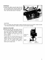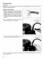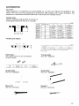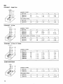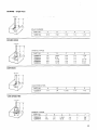
1
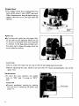
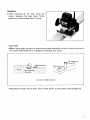
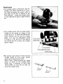
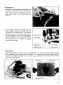
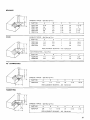
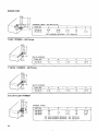
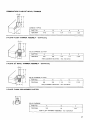
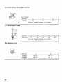
1/2"
MODEL 3612B
INSTRUCTION MANUAL
DOUBLE
INSULATION
Collet chuck
capacity
Main body
stroke
No load
speed
Overall
length
Net
weight
112"
0
65 mm
(0 - 2-9/16")
23,000
R/min.
287 m m
(1 1-5/16")
5 7 kg
(12.7 Ibs)
~
IMPORTANT
SAFETY INSTRUCTIONS
(For All Tools)
WARNING: WHEN USING ELECTRIC TOOLS, BASIC SAFETY PRECAUTIONS SHOULD ALWAYS BE FOLLOWED TO
REDUCE THE RISK OF FIRE, ELECTRIC SHOCK, AND PERSONAL INJURY, INCLUDING THE FOLLOWING:
READ ALL INSTRUCTIONS.
1. KEEP WORK AREA CLEAN. Cluttered areas and benches invite injuries.
2. CONSIDER WORK AREA ENVIRONMENT. Don't use power tools in damp
or wet locations. Keep work area well lit. Don't expose power tools t o rain.
Don't use tool in presence of flammable liquids or gases.
3. KEEP CHILDREN AWAY. All visitors should be kept away from work area.
Don't let visitors contact tool or extension cord.
4.STORE IDLE TOOLS. When not in use, tools should be stored in dry, and high
or locked-up place
- out
of reach of children.
5 . DON'T FORCE TOOL. It will do the job better and safer at the rate for which
it was intended.
6. USE RIGHT TOOL. Don't force small tool or attachment t o do the job of a
heavy-duty tool. Don't use tool for purpose not intended.
7 . DRESS PROPERLY. Don't wear loose clothing or jewelry. They can be caught
in moving parts. Rubber gloves and non-skid footwear are recommended
when working outdoors. Wear protective hair covering t o contain long hair.
8.USE SAFETY GLASSES. Also use face or dust mask if cutting operation is
dusty.
9. DON'T ABUSE CORD. Never carry tool by cord or yank it t o disconnect from
receptacle. Keep cord from heat, oil, and sharp edges.
IO. SECURE
WORK. Use clamps or a vise t o hold work. It's safer than using
your hand and it frees both hands t o operate tool.
1 1 . DON'T OVERREACH. Keep proper footing and balance at all times.
12. MAINTAIN TOOLS WITH CARE. Keep tools sharp and clean for better and
safer performance. Follow instructions for lubricating and changing accessories. Inspect tool cords periodically and if damaged, have repaired by authorized service facility. inspect extension cords periodically and replace i f
damaged. Keep handles dry, clean, and free from oil and grease.
2
13. DISCONNECT TOOLS. When not in use, before servicing, and when changing accessories, such as blades, bits, cutters.
14. REMOVE ADJUSTING KEYS AND WRENCHES. Form habit of checking t o
see that keys and adjusting wrenches are removed from tool before turning
it on.
15. AVOID UNINTENTIONAL STARTING. Don't carry plugged-in tool with finger
on switch. Be sure switch is OFF when plugging in.
16. OUTDOOR USE EXTENSION CORDS. When tool is used outdoors, use only
extension cords intended for use outdoors and so marked.
17. STAY ALERT. Watch what you are doing, use common sense. Don't operate
tool when you are tired.
18. CHECK DAMAGED PARTS. Before further use of the tool, a guard or other
part that is damaged should be carefully checked t o determine that it will
operate properly and perform its intended function. Check for alignment of
moving parts, binding of moving parts, breakage of parts, mounting, and any
other conditions that may affect its operation. A guard or other part that
is damaged should be properly repaired or replaced by an authorized service center unless otherwise indicated elsewhere in this instruction manual.
Have defective switches replaced by authorized service center. Don't use
tool if switch does not turn it on and off.
19. GUARD AGAINST ELECTRIC SHOCK. Prevent body contact with grounded
surfaces. For example; pipes, radiators, ranges, refrigerator enclosures.
20. REPLACEMENT PARTS. When servicing, use only identical replacement parts.
VOLTAGE WARNING: Before connecting the tool t o a power source (receptacle,
outlet, etc.) be sure the voltage supplied is the same as that specified on the
nameplate of the tool. A power source with voltage greater than that specified
for the tool can result in SERIOUS INJURY t o the user - as well as damage t o
the tool. If in doubt, DO NOT PLUG IN THE TOOL. Using a power source with
voltage less than the nameplate rating is harmful t o the motor.
3
ADDITIONAL SAFETY RULES
1. These bits come fully sharpened. Handle them carefully t o prevent injury.
2. Check the bit carefully for cracks or damage before operation. Replace
cracked or damaged bit immediately.
3. Avoid cutting nails. Inspect for and remove all nails from the workpiece before operation.
4. Make sure the shaft lock is released before the switch is turned on.
5. Hold the tool firmly with both hands.
6. Keep hands away from rotating parts.
7. Check the bit is not contacting the workpiece before the switch is turned on.
8. Before using the tool on an actual workpiece, let it simply run for several
minutes first. Watch for flutter that might be caused by poor installation or
a poorly balanced.
9. Be careful of the bit rotating direction and the feed direction.
IO. Do not leave tool running. Operate the tool only when hand-held.
11. Always switch off and wait for the bit t o come t o a complete stop before
removing the router from workpiece.
12. Do not touch the bit right after operation, it is extremely hot and could burn
your skin.
13. Keep the bit retracted so as not t o protrude from the bottom except during
actual operation.
SAVE THESE INSTRUCTIONS.
4
Installing bit
Loosen the collet nut and insert the bit
into the chuck hole. Press the shaft lock
and use the wrench to secure the bit carefully. Use the collet sleeve if necessary.
0
I
CAUTION :
0 Do not tighten the collet chuck without inserting a bit; do not install a small bit without using a collet sleeve. Either can lead t o collet chuck breakage.
Adjusting cutting depth
Release the lock lever and lower the tool
to the desired depth. Then pull up on the
lock lever to lock. Now adjust the stopper
block and pole so that, even if the lock
lever i s released, the router stops a t the
uniform depth.
If you press the fast-feed button on the
stopper pole, the pole can be advanced
rapidly. Ordinarily the pole moves 1.5 mm
(1/16”) per turn. Minute depth adjustments can be obtained by raising or
lowering the stopper pole.
5
Stopper block
.The stopper block has an adjustment hex
bolts which move 1 mm (1/32")per turn.
After obtaining the desired depth setting,
tighten the hex nut on the bolt with the
spanner.
I
\
block
Nylon nut
By turning the nylon nut, the upper limit
of the tool can be adjusted. When the tip
of the bit i s retracted more than required
in relation to the base plate surface, turn
the nylon nut to lower the upper limit for
more effective routing.
CAUTION :
Do not lower the nylon nut too low or the bit will dangerously protrude.
0
0
Before operating the tool, check to be sure that the router automatically rises to the
upper limit.
Switch action
*To start the tool, position the switch
lever t o "ON" side. To stop, to "OFF"
side.
CAUTION
Prevent accidental starting by making
sure the tool is switched off before you
plug it in.
6
Switch lever
Operation
*After switching on the tool, lower the
router, keeping the base plate firmly
against the work surface while routing.
CAUTION
0 When doing edge routing, the workpiece surface should be on the left side of the bit in
the router feed direction or a dangerous kickback may result.
(3 Bit revolving
direction
Correct bit feed direction
0
Adjustment should not be more than 15 mm (5/8")a t once when using straight bit.
7
Straight guide
.The straight guide is effectively used for
straight cuts when chamfering or grooving. When grooving, the router tends to
pull away to the left in relation to the
feed direction. Install the straight guide
on the right side to assure a good finished
cut.
.The straight guide with the guide holder
installs on the router by means of the
thumb bolts A. To obtain the desired distance between the bit and the straight
guide, turn the fine adjustment screw
(1.5"
or 1/16" per turn). Then tighten
the thumb bolt B to secure the straight
guide in place.
Thumb bolt A
Thiimh hnlt
B
Fine adjustment screw
B y bolting larger pieces of wood onto the
straight guide, an even larger (wider)
guide can be obtained as shown.
When using a board-jointing bit, attach
pieces of wood to the straight guide
which have a thickness of more than
15 mm (5/8") so that the bit does not
strike the straight guide.
(23/16")
55 mm
(23/16")
8
Trimmer guide
.Trimming, inside work and curved cuts in
veneers for furniture and the like can be
done easily with the trimmer guide. The
guide roller rides the curve and assures a
fine cut.
*The trimmer guide can be attached to the
guide holder with the thumb bolt B.
Loosening the thumb bolt B, the distance
between the bit and the guide surface
can be adjusted by the fine adjustment
screw (1.5 mm or 1/16" per turn). When
the thumb bolt C is released, the guide
roller can be moved.
1
ment s c r e w
I
Thumb bolt B
1 \ f' /
I
\
Guide roller
Thumb bolt C
1
I
Templet guide
.The templet guide provides a sleeve through which the router bit passes, when making
exact duplicates of a given pattern (templet). The templet guide i s installed by loosening the two panhead screws on the router base, inserting the templet guide and then
securing the two screws.
9
MAINTENANCE
CAUTION :
Always be sure that the tool is switched off and unplugged before attempting to perform
inspection and maintenance.
Replacing carbon brushes
0 Remove and check the carbon brushes
regularly. Replace when they wear down
to about 6 mm (1/4") or less. Keep the
brushes clean and free to slip in the
holders. Both brushes should be changed
a t the same time. Use only Makita carbon
brushes.
0
Use a screwdriver to remove the brush
holder cap as shown on the figure.
k 4
6 mm (1 /4")
BNSh holder cap
.Take out the worn brush, insert the new
one and secure the brush holder cap.
Any other maintenance should be performed by an Authorized Makita Service Center or
point of purchase.
10
ACCESSORIES
CAUTION :
These accessories or attachments are recommended for use with your Makita tool specified in this
manual. The use of any other accessories or attachments might present a risk of injury to persons. The
accessories or attachments should be used only in the proper and intended manner.
Templet guide
Used for finishing a large quantity of articles of
complicated shapes with the use of a templet.
!mml
Part
NO.
I Templet w d e I
A
I
I
E
C
Templet guide adapter
~~~
Pari No
321492 3
Collet sleeve
Use a sleeve which fits for the diameter
of the bit shank.
s 2e
Pirt No
s Le
A
E
30 11-3/15 'I
35 11.3/8''1
1
~~
C
7 19132"l
Trimmer guide
(Part No. 123022-4)
Part No
Straight guide
(Part No. 342428-9)
Guide holder
(Part No. 122256-6)
Wrench 24
(Part No. 781210-5)
Wrench 8
(Part No. 781213-9)
11
Bits
STRAIGHT -Single Flute
CARBIDE TIPPED
I
PARTNO.
A
B
C
0
E
733002-0A
733002-4A
3/8
1/2
1
1-1/4
1-1/2
1-3/8
1/2
112
2-3/4
2-7/8
HIGH SPEED STEEL
STRAIGHT
PART NO.
A
B
C
0
E
733232-6A
118
5/16
Vl/8
1/4
1.518
- 2 Flute
CARBIDE TIPPED
PART NO.
A
B
C
D
733003-2A
733003-4A
733003-8A
3/16
1/4
5/16
7/16
3/4
1
1-3/8
1-3/16
1-1/8
1/4
114
114
E
2
2-1/ 8
2-3/16
HIGH SPEED STEEL (STRAIGHT - 2 Flute)
STRAIGHT
PART NO.
A
B
C
0
E
733233-4A
733234-2A
5/16
1/ 2
7/8
718
1-3/16
1-1/8
1/4
1/4
2-118
2-118
112
3/4
7/8
1-1/4
1-1/2
1-1/4
1-1/4
1-1/4
1-1/4
1-7/16
1-1/4
1-1/4
1-3/16
1-3/16
- 2 Flute, 1/2” Shank
CARBIDE TIPPED
PART NO.
7330054A
733005-6A
733005-8A
733006-4A
733006-6A
733006-8A
2-1/2
2-718
112
1/2
112
2.112
2-112
2-1/2
HINGE MORTISING
CARBIDE TIPPED
PART NO.
A
B
C
0
E
733006-9A
112
1/2
1-1/16
1/4
1-13/16
HIGH SPEED STEEL
12
PART NO.
A
B
C
D
E
733235-0A
1/ 2
1/2
314
1/4
1-15/16
VEINING -Single Flute
SOLID CARBIDE
PART NO
A
B
C
D
E
733007-8A
3/16
7/32
1-114
114
1-112
ROUND NOSE
CARBIDE TIPPED
&
PART NO
A
8
C
D
E
733008-2A
733008-4A
7330086A
733008-8A
733009-0A
114
318
112
15/32
9116
11116
11116
13116
1-114
1-114
1-114
1-114
1-114
114
114
114
114
114
1-718
2
2-3116
2.114
2-318
518
314
CORE BOX
4D c--
-J
HIGH SPEED STEEL
PART NO.
A
B
C
D
E
733238-2A
114
114
1.3116
114
1-112
I
I
VEE GROOVING
CARBIDE TIPPED
PART NO.
A
B
C
D
E
F
733009-2A
733009-4A
114
7116
112
314
1-3/16
15/16
114
114
2
2
318
518
13
14" DOVE TAIL
CARBIDE TIPPED
PART NO.
A
B
C
D
E
733009-6A
1I2
112
1-1/4
114
1-718
HIGH SPEED STEEL
PART NO.
A
B
C
D
E
733239-6A
112
112
1-318
114
2
STAGGER TOOTH
-ID!-
CARBIDE TIPPED
PART NO.
A
B
C
D
E
733007-0A
318
1-112
1-1I 4
112
3
PART NO.
A
B
C
D
E
733030-4A
733030-6A
318
112
1
1 118
1
1-1/2
318
112
2-1/2
3-114
PANEL PILOT
CARBIDE TIPPED
HIGH SPEED STEEL
CORNER ROUNDING
PART NO.
A
B
C
D
E
733236-0A
114
314
1
114
2-7116
CARBIDE TIPPED
- Ball Bearing Pilot
PART NO.
A
B
C
0
E
7331 20-OA
733120-2A
7331 20-4A
733120-6A
7331 20-8A
733121 -0A
733121 -2A
3/16
1/4
5/16
318
1/2
318
112
318
1/2
112
518
314
5/8
314
1-1/4
1-1I 4
1-114
1-1/4
1-114
1-112
1-1I2
114
114
114
1I 4
114
112
1/2
1-15/16
2
2-1/16
2-118
2.114
2-318
2-112
REPLACEMENT BEARING - NO 733132-4A
~
HIGH SPEED STEEL - Solid Pilot
14
PART NO.
A
B
C
D
E
733240-2A
733240-6A
114
318
1/2
518
1
1
114
114
1-314
1-718
BEADING
CARBIDE TIPPED - Ball Bearing Pilot
COVE
PART NO.
A
B
C
D
E
733121-4A
7331 21 -6A
7331 21-8A
733122-0A
7331 2 2 - 2 A
3116
114
5116
318
112
318
112
112
518
314
1-114
1-114
1-114
1-114
1-114
114
114
114
114
114
1.15116
CARBIDE TIPPED
i
~
2
2.1116
2-118
2-114
Ball Bearing Pilot
PART NO
A
B
C
D
E
733122-6A
733122-8A
733123-0A
114
318
112
318
112
518
1
1
1
114
114
114
1-518
1-314
1.718
REPLACEMENT BEARING - NO 733132-2A
HIGH SPEED STEEL -Solid Pilot
PART NO.
A
B
C
D
E
733242-6A
733242-BA
114
318
112
314
1
1
114
114
1-314
2-1/32
45" CHAMFERING
4DI-
CARBIDE TIPPED - Ball Bearing Pilot
PART NO.
A
€3
C
D
E
F
733124-4A
112
112
1-114
114
2-114
1-3116
REPLACEMENT BEARING - NO. 733132-4A
RABBETING
-1DC
CARBIDE TIPPED - Ball Bearing Pllot
PART NO.
A
B
C
D
E
F
7331 2 4 - 2 A
318
112
1-7/16
1/4
2.114
1-114
REPLACEMENT BEARING - NO. 733132-4A
15
ROMAN OGEE
CARBIDE TIPPED - Ball Bearing Pilot
PART NO.
A
B
C
D
E
7331 23-2A
733123-4A
5/32
1I 4
15/32
21/32
1.114
1-114
1/4
1I4
2
REPLACEMENT BEARING
2.118
- NO. 733132-2A
FLUSH TRIMMER -Self Piloting
SOLID CARBIDE
7’ BEVEL TRIMMER
PART NO.
A
B
C
D
E
733128-0A
1/4
1/4
1-1/16
114
1-9/16
- Self-Piloting
SOLID CARBIDE
PART NO.
A
B
C
D
E
7331 28-2A
3/16
1I 4
1-1/16
114
1-9/16
PARTNO.
A
B
C
D
E
7331 28-8A
7331 28-9A
7331 29-OA
3/8
1I2
112
1
1-1I 4
1-114
1-1/4
114
114
114
2-1/16
2-1/16
2-518
2 FLUTE FLUSH TRIMMER
CARBIDE TIPPED
I
1I2
1
3/8” REPLACEMENT BEARING - NO. 733132-2A
112” REPLACEMENT BEARING - N O . 7331324A
16
COMBINATION FLUSH122" BEVEL TRIMMER
CARBIDE TIPPED
PART NO.
A
B
C
D
E
7331 28-6A
7116
112
1-114
114
1-314
~~
3 FLUTE FLUSH TRIMMER ASSEMBLY -Self Piloting
SOLID CARBIDE CUTTER
PART NO.
A
8
C
D
E
733129-2A
518
318
1-114
114
2-318
REPLACEMENT BEARING - NO. 733132-6A
3 FLUTE 22" BEVEL TRIMMER ASSEMBLY -Self Piloting
SOLID C RBlDE CUTTER
PART NO.
A
B
C
0
E
7331 29-4A
518
3/8
1-114
114
2-318
REPLACEMENT BEARING - NO.733132-6A
3 FLUTE FLUSH REPLACEMENT CUTTER
TL
A
pJ
SOLID CARBIDE
PART NO.
7331 29-6A
A
B
C
3/8
114
518
FOR FLUSH TRIMMER ASSEMBLY NO. 733129-2A
17
3 FLUTE 22" BEVEL REPLACEMENT CUTTER
L
A
t
SOLID CARBIDE
I
PARTNO.
A
733129-8A
318
8
C
FOR BEVEL TRIMMER
1/4"REPLACEMENT ARBOR
PART NO.
A
B
C
D
E
733131-2A
1/4
318
1-114
1I 4
2.318
FOR FLUSH TRIMMER ASSEMBLY NO. 733129-2A
AND NO. 733129-4A
BALL BEARING PILOT
18
PART NO.
A
B
733132-2A
733132-4A
733132-6A
318 O.D.
1/2 O D .
5/8 O.D.
118 I.D.
3/16 I.D.
1/4 ID.
Jan - 2 4 -'E6 EN
12 mm (1/2")
ROUTER
Model 3612B
19
Jan
MODEL 36128
‘EMAiD
$&
DESCRIPTION
MACHINE
24
86 EN
DESCRIPTION
MACHINE
~
~
1
1
1
1
1
4
1
2
3
4
5
6
2
7
8
9
10
11
12
13
14
15
16
17
18
19
4
1
1
1
1
1
4
1
1
2
1
1
1
1
1
1
1
1
1
1
1
1
1
20
21
22
23
24
25
26
27
28
29
30
31
32
-
1
1
-
Nut M 1 0
Nylon Nut M 1 0
M O ~ Onourlng
~
Name Plate
Rivet 0 5
FIELD ASSEMBLY
Hex Bolt M5xB5 [With Washer]
Countersunk Head Screw M4x14 [With Washer]
Ball Bearing 201 2LLB
Knob L
Motor Bracket
Compression Spring 10
Half Nut
Pan Head Screw M5x40 [With Washer)
Collet Nut
Collet cone
Pan Head Screw M6x40 lWith Washer)
Knob R
Compression Sprmg 1 0
Set 8011 M 1 0
Lock Lever
Spring Washer 5
Hex Bolt M5x12
Retaining Ring R - 12
Pin 6
Compression Spring 7
Screw M 10x77
Bearing Retainer 50
Fan 92
ARMATURE ASSEMBLY
IWith Ikem 9 & 29 - 321
Insulation Washer
Ball Bearing 6200LB
33
34
35
1
36
37
38
1
1
1
1
39
2
40
41
42
43
44
45
46
1
1
41
48
49
50
51
52
53
54
55
56
57
58
59
60
61
62
63
64
65
Wave Washer 2 0
Pan Head Screw M5x12 iWith Washer]
Baffle Plate
Chip Deflector
Noise S ~ p p r e s s m
Switch
Pan Head Screw M4x14 [With Washer)
Strain Relief
Switch Cover
Pan Head Screw M4x20 IWith Washer1
Hex Nut
Brush Holder Cap
Carbon Brush
Cord Guard
Cord
Pole
Compression Spring 11
2
2
1
2
2
1
1
1
2
1
2
Base
Wing Bolt M6x 15
C o m p r e r r m sprmg 9
Hex 8011 M5x16
Hex Nut M 5
nex soit ~ 5 ~ 4 0
Hex Nut M 5
Screw M 6
Compression Spring 12
Hex Bolt M5x28
Hex Nut M 5
stopper
Pan Head Screw M5x10 lWith Washer)
Countersunk Head Screw M4x8
2
1
1
1
1
1
1
1
1
1
2
4
1
Base Plate
S p m g P,” 5 - 1 8
2
Note: The switch. noise suppressor and other part Specifications may differ from country to country
f
MAKITA LIMITED ONE YEAR WARRANTY
Warranty Policy
Every Makita tool is thoroughly inspected and tested before leaving the factory. It is warranted to
be free of defects from workmanship and materials for the period of ONE YEAR from the date of
original purchase. Should any trouble develop during this one- year period, return the COMPLETE
tool, freight prepaid, to one of Makita’s Factory or Authorized Service Centers. If inspection shows
the trouble is caused by defective workmanship or material, Makita will repair (or at our option.
replace) without charge.
This Warranty does not apply where:
repairs have been made or attempted by others:
repairs are required because of normal wear and tear:
0 The tool has been abused, misused or improperly maintained;
alterations have been made to the tool.
IN NO EVENT SHALL MAKITA BE LIABLE FOR ANY INDIRECT, INCIDENTAL OR CONSEQUENTIAL DAMAGES FROM THE SALE OR USE OF THE PRODUCT. THIS DISCLAIMER
APPLIES BOTH DURING AND AFTER THE TERM OF THIS WARRANTY.
MAKITA DISCLAIMS LIABILITY FOR ANY IMPLIED WARRANTIES, INCLUDING IMPLIED
WARRANTIES OF “MERCHANTABILITY” AND “FITNESS FOR A SPECIFIC PURPOSE,”
AFTER THE ONE-YEAR TERM OF THIS WARRANTY.
This Warranty gives you specific legal rights, and you may also have other rights which vary from
state to state. Some states do not allow the exclusion or limitation of incidental or consequential
damages, so the above limitation or exclusion may not apply to you. Some states do not allow
limitation on how long an implied warranty lasts, so the above limitation may not apply to you.
-
W
FIIrtkirwana,ud.
11-8, 3-chome, Sumiyoshi-cho, Anjo, Aichi 446, Japan
883503A069
P R I N T E D IN JAPAN
1986-9-N