1
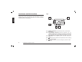
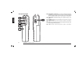
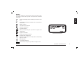
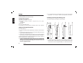
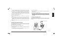
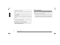
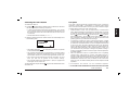
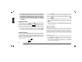
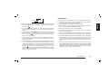
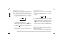
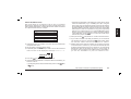
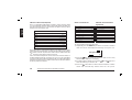
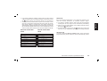
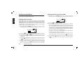
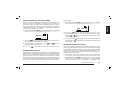
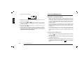
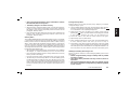
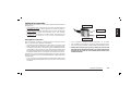
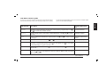
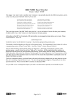
1
2
2
3
4
4
4
5
6
7
8
8
8
8
9
9
10
11
11
12
12
12
13
14
14
14
15
16
16
16
16
17
"Who-has-called" call (Call Queue)
Manual call
One touch call
ADVANCED OPERATIONS
Sending status messages
Sending FFSK free messages (SDM)
Checking FFSK free messages (SDM)
Sending dtmf patterns
Handsfree transmission (VOX)
CARE AND MAINTENANCE
Battery packs
Information on rechargeable batteries
Properly charge of battery packs
Memory effect
Erasing memory effect
Warnings for battery and chargers use
Radio maintenance
Cleaning battery packs
Cleaning the radio
Connectors
OPTIONAL ACCESSORIES
Microphone connector
QUICK REFERENCE
Operation resume
LCD memo reference guide
MAIN SPECIFICATIONS
General
Transmitter
Receiver
AF & signalling
Mechanical specs
INDEX
In this book...
18
19
19
20
20
20
21
21
21
22
22
22
22
23
23
23
24
24
24
24
25
25
26
26
27
29
29
29
29
30
30
31
1
English
IN THIS BOOK…
Introduction
Warning notes
Safety
Conventions and symbols in this book
PART NAMES AND THEIR FUNCTIONS
Top
Front
Side (left and right)
Display
SETUP
Unpacking
Fitting/removing the antenna
Installing/removing the battery pack
Installing/removing the belt clip
Charging the battery pack
BASIC OPERATIONS
Switching the radio on/off
Reception
Adjusting volume
Channel selection
Adjusting squelch
Transmission
Adjusting transmission power
Adjusting display contrast
Scanning channels
Radio lock
SELCALL AND CTCSS/DCS OPERATION
Reception
Transmission
Sending a Selcall
Stored call (Address book)
English
Introduction
Warning notes
Congratulations. HP 125-K/HP 425-K is an advanced PMR
(Professional Mobile Radio). Its rugged design allows it to be your
reliable partner even during hard working days. Its large LCD as well
as user friendly controls make the maximum ease of use.
HP 125-K/HP 425-K is a real system radio, supporting CTCSS/DCS,
5 tone signalling systems (encoder/decoder up to 28 + 28 tones),
FFSK, DTMF and trunking system property. Selcall mode supports
also many facilities, such as an alphanumeric address book, a call
queue function as well as a status message table. You can also use
FFSK to send/receive short text messages which you can dial via the
alphanumeric keypad. The way your radio operates may be upgraded
and may differ from what is described here.
To extend the flexibility the radio is provided with VOX function, which
allows to switch the transmission just by talking in full hands free
condition.
Since standard operation can be changed by programming, the
functions the radio includes and the buttons used to activate them
can be modified. For this reason some commands couldn’t be
available. Please contact your radio network administrator or dealer
for further details.
Transceiver’s specifications provided in HP 125-K/HP 425-K are
compliant with ETS 300 086 and ETS 300 113, moreover its top level
design and resistance are compliant with IEC529 level IP54 and MIL
STD 810 C,D,E.
CTE International is committed to continuous quality improve, for this
reason specifications may vary without prior notice.
Every effort has been made to ensure that the information in this
document is complete, accurate, and up-to-date. CTE International
assumes no responsibility for the results of errors beyond its control.
The manufacturer of this equipment also cannot guarantee that
changes in the equipment made by non authorized people will not
affect the applicability of the information in it.
This user’s guide is subject to change without notification. This booklet
is referred to 1.0 software version. If you own a later one please
contact CTE International for the most recent updates.
Safety
Your HP 125-K/HP 425-K handheld transceiver has been carefully
designed to give you years of safe, reliable performance. As with all
electrical equipment, however, there are a few basic precautions you
should take to avoid hurting yourself or damaging the radio:
• Read the instructions in this handbook carefully. Be sure to save
it for future reference.
• Read and follow all warning and instruction labels on the radio
itself.
• Don’t carry the transceiver by the antenna. This may damage
the antenna or antenna terminal. Grasp it by its base (not the tip!)
when you need to place or remove it.
• Don’t keep the radio with the antenna very close to, or touching
exposed parts of the body, while transmitting. The radio will perform
best if the microphone is 5-10 cm away from the mouth and the
radio is vertical.
• Be sure the PTT key is not depressed when you don’t need to
transmit.
• Do not operate the radio near unshielded electrical blasting caps
2
Introduction
This product complies with the requirements of the Council Directives
89/336/EEC and 73/23/EEC on the approximation of the laws of the
member states relating to electromagnetic compatibility and low
voltage.
Conventions and Symbols in this Book
2 This symbol marks a ‘note’. Notes are hints or tips which offer
additional information to help you.
I This symbol marks a ‘caution’. Cautions are special notices
which you should read and follow carefully to avoid possible
damage to your equipment and to avoid potential danger to
yourself or other people.
Key names will be highlighted in bold.
Important sentences and words are highlighted in Italic.
LCD messages which may appear on the transceiver’s display are
highlighted in Courier New
Introduction
3
English
or in an explosive atmosphere.
• Don’t transmit without the antenna fitted on the radio. Though
it is provided with a protection, it may damage the TX output final
stage.
• Respect the environment conditions. The radio is designed to
be used in heavy environments, however avoid to expose it to
extremely hot or cold temperature (out of the range between –30
to +60°C). Don’t expose the transceiver to excessive vibrations
as well as dusty or rainy places.
• Never try to disassemble or service the radio by yourself (aside
from the routine maintenance described in this handbook). It will
immediately void the warranty and you may cause damage requiring
extensive repair work. Always contact your local dealer for
assistance.
• Grasp your radios firmly. Otherwise it may fall and be damaged.
• Use only genuine accessories. Non original ones could seriously
damage your handheld transceiver.
• Do not use your radio near water, or spill liquid of any kind
into it. If the transceivers get wet immediately dry it by a soft and
clean cloth.
• Switch the radio off before you clean it. Strictly follow the
directions reported in the paragraph “Care and maintenance”.
• Handle the battery properly. Strictly follow the directions reported
in “Care and maintenance”.
• Be certain that your power source matches the rating listed for
the supplied battery charger (AC adaptor). If you are not sure,
check with your dealer or with your local power company.
• To avoid damaging the power cable of the battery charger, do not
put anything on it or place it where it will be walked on.
Part Names and their functions
Top
Please have a look to the following parts description in order to
familiarize with the transceiver’s main parts and controls. Numbers
in brackets refer to the illustration.
1
English
5
4
3
[1]
[2]
[3]
4
Part Names and their functions
2
Antenna connector. Fit the antenna to this connector (MX
thread type).
Programming connector (under the protection cap - for
authorized dealers/service stations only). Allows to program the
radio (channels data) via a suitable programmer. It must be
protected with the supplied rubber cap when not in use.
Status LED. Glows in different colors to show the current radio’s
status.
[4]
(monitor) button. Enables the loudspeaker for audio monitoring
of the tuned channel.
[5]
emergency button. Sends the emergency selective call (if
enabled).
[6]
Speaker. The reception sound is emitted by the built in speaker
located in this point.
[7]
(power) button. Keep pressed this key to turn the transceiver
on and off.
LCD display. Shows the radio’s parameters (channel number
etc.). Icon and symbols are further explained in the paragraph
“Display”. Whenever any key is pressed the display is
automatically backlit for few seconds.
[8]
6
(up) and
(down) buttons. For scrolling forward and
backward through function list and for changing function values.
[10] Keypad. For entering digits of selective call (if enabled) and
letters for the related operations (e.g. SDM messages or Address
Book). Whenever any key is pressed the display is automatically
backlit for few seconds.
[9]
7
14
8
9
MENU
13
1 CB
A
2 EF
D
3 HI
G
4 KL
J
5 ON
M
6 QR
S
8WX
V
9 -Z
P
[11]
(clear) button. If held pressed in command menu escapes
it and reverts the radio in standby condition. In Selcall mode
deletes wrong entered digits (if enabled).
(call) button. To send a valid call when using selective call
features (Selcall - if enabled).
[13] MENU button. Allows to access the main menu.
[14] Microphone. Your voice is detected by the microphone located
in this place.
[12]
10
7 UT
12
C
A
L
L
Y
C
L
R
0
11
®
Part Names and their functions
5
English
Front
Side (left and right)
English
20
15
19
18
17
16
6
Part Names and their functions
[15] Microphone connector. For remote speaker/microphone,
headsets for VOX use and other accessories. It must be protected
with the supplied rubber cap when not in use. For the related
pin connections please see to “Microphone connection”.
[16] Battery pack. This NiMH battery pack supplies energy to your
radio.
[17] Release button (located on the battery’s body). Allows to remove
the battery pack.
[18] CALL 1 button. Sends the selective call NO.1 (if enabled).
[19] PTT (Push To Talk) button. When pressed switches the transceiver
from reception to transmission.
[20] CALL 2 button. Sends the selective call NO. 2 (if enabled).
Display
This section explains the meaning of the various indications which
may appear on the LCD of your HP 125-K/HP 425-K handheld
transceiver:
English
Radio is transmitting (status LED will glow red at the same
time)
Loudspeaker is enabled (you will hear audio communications
and/or noise)
DTMF is enabled
CTCSS/DCS tone detected
Selective call detected
Scrambler enabled
Battery Level (as many bars you will see as higher is the
residual duty)
Keypad lock enabled
Receive mode (squelch is open)
Reception field strength level
transmission output power currently selected, respectively
high (H) or Low (L)
Mail notification
Customizable operation
Volume level (as many bars you will see as higher is the
Part Names and their functions
7
2
Setup
English
Unpacking
The following items are in the package:
(a) Transceiver’s main body
(b) Rubber ducky antenna
(c) Battery pack NiMH 1,200 mA/h
(d) Standard battery charger composed by two parts:
• Cradle
• AC adapter
(e) Belt clip
(f) User’s guide (this book!)
If something is missing please promptly advise your supplier.
The supplied antenna is broadband type and covers the whole
spectrum, so it doesn’t need any alignment procedure.
Installing/removing the battery pack
To install the battery pack (please see the figure):
transceiver
back edge
2 cm
Fitting/removing the antenna
To fit the antenna:
1) Locate the antenna terminal (thread MX connector) on transceiver’s
top.
2) Hold the transceiver with one hand and the base (the thicker part)
of the antenna with the other one.
3) Attach the included rubber ducky antenna to the antenna terminal
by turning it clockwise until it is firmly locked. Don’t overtight it.
To remove the antenna do the same described procedure. At step 3
turn the antenna base counterclockwise.
I Leave the antenna fitted on the radio. You can’t communicate
without it. Moreover, transmitting without the antenna may
damage the TX output final stage. For the same reason use
only the supplied antenna.
8
Setup
battery
pack
1
2
3
4
1) Hold the transceiver’s body with one hand and the battery pack
with the other. Put the battery pack onto the metallic back of the
transceiver as shown at approximately 2 cm from its back edge.
To remove the belt clip:
1) Remove the battery pack as explained in “Installing/removing the
battery pack”.
2) Reverse the over stated step 2.
I Don’t forget to remove the battery pack before fitting/removing
the belt clip, otherwise the operation may result harder to
perform. Moreover the battery case might be accidentally
scratched.
Charging the battery pack
To charge the supplied battery pack you have to setup the supplied
standard charger and connect the radio as follows (please see the
picture):
To the AC outlet
Installing/removing the belt clip
The supplied belt allows you to hang the transceiver up to your belt
or jacket when you are not using the radio and you are just in standby condition (ready to receive calls).
To fit the belt clip onto the transceiver’s body:
1) Remove the battery pack as explained in “Installing/removing the
battery pack”.
2) Just gently slide the clip into the appropriate guides located in
the transceiver’s back until it firmly locks.
MENU
1 CB
A
2 EF
D
3 HI
4 KL
J
5 ON
M
6 QR
S
8WX
V
9 -Z
7 UT
C
A
L
L
G
P
Y
C
L
R
0
®
Setup
9
English
2) Gently slide the battery pack toward the transceiver’s back edge
keeping it slightly pressed onto the metallic back surface.
3) At approx. 1.5 cm you will feel the battery’s guides fitting with the
transceiver’s ones (the battery pack will be closer to the transceiver).
Keep on sliding the battery pack toward the back edge.
4) At the end you will hear a click: the battery pack will snap into
place and should be firmly locked.
To remove the battery pack:
1) Press the battery release button located in the back of the battery
pack.
2) Keep the button pressed and gently pull the battery pack away
from the transceiver back edge (the opposite operation of the
previous step 2): it will stop at 1.5 cm approximately and will be
free.
3) Remove the battery pack by separating it from the transceiver’s
body.
English
1) Connect the jack coming from the AC adaptor to the cradle’s
socket located in its right side.
2) Connect the AC plug of the AC adaptor’s power cable into an
earthed AC power outlet: the built-in green LED of the cradle will
glow.
3) Ensure that the radio is switched off, otherwise switch it off by
holding the
(power) key pressed (release it after the radio is
switched off).
4) Insert the radio into the cradle with the keypad toward you (the
three metallic contacts of the battery pack must touch with the
three contacts inside the cradle): the built-in red LED of the cradle
will glow.
5) Wait 8-9 hours and remove the radio after that time.
2
Don’t remove the radio before 8 hours, otherwise the battery’s
duty could be temporarily reduced.
I Don’t forget to remove the radio after 9 hours.
I The battery charger is for indoor use only.
I For the next charges, best duty and battery life please fully
see the chapter “Battery Packs”.
10
Basic Operations
Basic Operations
This section describes how the standard operations work. Standard
operation can be changed by programming, moreover the functions
the radio includes can be modified via an IBM compatible PC. For
this reason the way your radio operates may be upgraded and may
slightly differ from what is described here.
2
IMPORTANT: Due to the full programmability of the radio, certain
menu commands could be unavailable. E.g. if your radio hasn’t
been programmed for selective call operations, the related menu
commands won’t be recalled. In case of doubts please contact
your dealer/radio network administrator for further details.
Reception
To switch the radio on:
Your radio could be previously programmed to work, channel by
channel, in “Open traffic”, “CTCSS/DCS” or “Selcall” mode. Please
have a look to each description and ask your radio network manager
or dealer which mode your radio channels work.
• OPEN TRAFFIC: in this case you will hear any communication
which will be transmitted on the selected channel. When any signal
is received your squelch will unmute and you will see in the LCD
(speaker enabled), (squelch is open),
(reception
the icon
field strength level – the number of bars will vary according to
the received RX strength). Moreover you will see the status LED
glowing green and you will hear the message.
• CTCSS/DCS (Continuous Tone Code Squelch System - Digital
Coded Squelch): they are systems which use particular TX signalling
(a continuous sub audio tone for CTCSS or a digital code for DCS)
as an access “key” to work a repeater (encoder) or to unlock the
party’s signalling sensitive squelch. This last condition allows to
share more radio networks in the same frequency. In this case
you will receive only messages coming from parties sending a
proper TX signalling. Please see the chapter “Selcall Operation”
for further details.
• SELCALL (Selective call): it’s a system which uses a signalling
sequence (e.g. audio tones for “5 tones” and DTMF selcall or a
frequency shift signalling for FFSK) to call a particular station or
group(s). In this case you will receive only calls provided with your
identification selective call code (a number) or calls sent to the
group you own. For further details please see the chapter “Selcall
operation”.
(power) button until the radio is switched on: the LCD
1) Hold the
will start an autotest showing in sequence:
• A welcome message (if previously programmed – it is usually
your company name or your personal station identification). At
the same time all the LCD icons will be shown for one second
as LCD test.
• The firmware release number (FW Rev.).
2) After the autotest has been carried out the LCD will steadily show
the following data:
CHANNEL 1
• The battery level with
. As many bars you will see, as greater
is the residual battery duty.
• The channel name/number on the first line (a specific twelve
alphanumeric characters identification name), it could be the
last recalled channel or a previously programmed specific one.
• The current volume level with an LCD bar indication. As more
bars you will see as greater is the volume setting.
• The currently selected TX output power: L (low) or H (high) in the
lower right corner of the LCD.
To switch the radio off just hold the
will switch off.
key pressed until the transceiver
2 CTCSS/DCS and Selcall can be combined together.
I CTCSS/DCS and Selcall allow to share more than one radio
Basic Operations
11
English
Switching the radio ON/OFF
English
network in the same frequency, however they are just useful
to avoid disturbing stations not owning of the same network
with messages not related to them. In any case, if more than
one station is transmitting at the same time, this will cause
an interference. Don’t transmit if the status LED is glowing
or the icon is on the LCD. Wait till nobody is transmitting
on the channel.
Adjusting volume
When no keys are pressed for 5 seconds, the radio is in its normal
condition (stand by) and the
(up) and
(down) keys are used
to adjust the RX volume: just repeatedly press the key to increase
provided in the bottom
or the key to reduce it. The bar meter
part of the LCD will continuously show the volume level; as many
bars you will see, as higher is the volume level currently selected.
2
You will later see that up and down keys are also used to adjust
other settings recalled by pressing once or more times the MENU
key. This key is used to access the command menu.
Channel selection
If your radio has been programmed with more than one channel you
can easily change it. As previously explained each channel is identified
by alphanumeric names which are previously defined by your network
manager or supplier. They should have designated appropriate names
for them in order to make easier for you quickly recognizing which
channel you are currently working in.
To select a channel:
Channel
12
Basic Operations
1) Press the MENU key in order to access the command menu and
see on the display the message Channel. Normally you have to
press the key just once, but if necessary repeatedly press it again.
2) Press the
key to increase the channel number or the
key to decrease it.
3) Press the MENU key repeatedly to go through the next menu item
or press and hold to go to the previous menu item, or press the
(clear) key to escape the menu and restore the normal LCD
condition.
2
After 5 seconds, if you are not pressing any key, the menu is
automatically escaped, so the display will automatically revert to
its normal condition.
Adjusting squelch
Squelch device provide to silence your radio when you are working
in open traffic mode (please see “Reception”) and no signals are
received. It’s very important to adjust it in order to set the minimum
level which assures you a stable silence in stand-by condition. If the
squelch level is too high, you might lose weak signals. A good squelch
adjustment assures also a proper scanning operation.
To adjust the squelch:
1) Ensure that no communications are carried out in the tuned channel
(the icon shouldn’t be present in the top right part of the LCD).
2) Repeatedly press the MENU key in order to access the command
menu and see on the display the message Squelch (normally
you have to press the key twice). You will also see a number which
is the squelch adjustment level.
key repeatedly to decrease the squelch level: after
3) Press the
the level 1 you will see OFF (squelch disabled) and you will also
see the icon .
4) Press the
key repeatedly in order to select the minimum
squelch level in which the icon steadily disappears (normally 2
will do).
5) Repeatedly press the MENU key repeatedly to go through the
next menu item or press and hold to go to the previous menu
item, or press the
(clear) key to escape the menu and restore
the normal LCD condition.
2
After 5 seconds, if you are not pressing any key, the menu is
automatically escaped, so the display will automatically revert to
its normal condition.
2
In case of either CTCSS or Selcall system programmed, squelch
could not affect the loudspeaker status, because the radio is closed
awaiting the right tones. In case of advanced signalling systems,
please, pay attention to the programming of the monitor key
function (further described). Depending on this, you can or not
press the
button to mute/unmute the loudspeaker and to adjust
the squelch level. The set squelch level will be stored and recovered
at every switch on operation.
Transmission
When you need to transmit please get used to follow all these steps:
1) Ensure that the channel is not busy (otherwise you will create an
interference, please wait till that condition).
2) Press the PTT key: the status LED will glow red.
3) Start talking at a normal voice level at approximately 10 cm from
the microphone (keep the PTT key pressed).
4) When your message is over, release the PTT
2
Don’t shout! It won’t increase the distance range, but rather will
make you heard distorted.
2
Don’t release the PTT before your message is over or start talking
before pressing it, otherwise your message will be “chopped”.
2
A PMR handheld radio doesn’t normally allow to talk and receive
simultaneously, for this reason make your messages with a
reasonable time. When you are talking the other parties can’t do
that, so don’t occupy too much the channel. Use the common
sense.
2
The radio might be programmed with a timeout timer which
automatically put your radio in reception if you talk too much (after
a preset time). In this case release the PTT and wait for few seconds:
the radio TX features will be automatically restored. Ask the network
responsible or your dealer for further details.
Basic Operations
13
English
3
Squelch
English
Adjusting transmission Power
Adjusting display contrast
Your HP 125-K/HP 425-K can transmit with two power levels according
to the distance of your party station(s). Low and High levels can be
defined by default during programming, however we do recommend,
when possible, to use the Low power: it will increase the battery duty
and will reduce the risk to make interference with stations not owning
to your radio network which may sharing the same channel with you.
1) Repeatedly press the MENU key in order to access the command
menu and see on the display the message Power (normally you
have to press the key three times). You will also see a cursor on
either L or H.
You can adjust the LCD contrast in order to obtain the best readability.
It will vary depending on your use as well as the environment
illumination.
1) Repeatedly press the MENU key in order to access the command
menu and see on the display the message Contrast (normally
four times).
H Power L
2) Change the power as follows:
• If the low power is currently selected, press the
the high power; the cursor will move to H.
key to set
• If the high power is currently selected, press the
key to set
the low power; the cursor will move to L.
3) Repeatedly press the MENU key repeatedly to go through the
next menu item or press and hold to go to the previous menu
(clear) key to escape the menu and restore
item, or press the
the normal LCD condition.
2
14
After 5 seconds, if you are not pressing any key, the menu is
automatically escaped, so the display will automatically revert to
its normal condition.
Basic Operations
Contrast
key repeatedly to increase the contrast or the
2) Press the
key to decrease it.
3) Repeatedly press the MENU key to go through the next menu
item or press and hold to go to the previous menu item, or press
the
(clear) key to escape the menu and restore the normal LCD
condition.
2
After 5 seconds, if you are not pressing any key, the menu is
automatically escaped, so the display will automatically revert to
its normal condition.
Scanning channels
If you have more than one channel programmed, your HP 125-K/HP
425-K can scan them: in other words it can cycle through them and
stop when a signal is detected.
The advanced scan functions of the radio allow to optionally preset
two groups (g1 and g2) in order to independently activate the scanning
g2
Scan
g1
2) Now you can activate the scan as follows:
• If you have only one group available press the
key.
• If you have two groups programmed, press
to scan the g2
to scan g1.
group or
• If you simultaneously want to scan the 2 groups, press and hold
g1 or g2.
In both cases you will see Scanning and the channel names cycling
continuously. The scanning starts from the lowest address number
toward the highest. Obviously, if one or more priority channels
have been programmed, it will start from the first priority address
number.
3) To stop channel scan Press the MENU key,
or the PTT.
2
If you are working in Open traffic (please see the paragraph
“Reception”) ensure that the squelch is properly set, otherwise
the scanning may not properly work. See eventually the paragraph
“Adjusting squelch” for more details.
2
If CTCSS/DCS or Selcall have been previously programmed, the
scanning will stop only if the received signal has the appropriate
signalling.
2
If you press the PTT during channel scan (on the LCD) it will stop
and transmit in the priority channel or in the first available vacant
channel, depending on programming.
2
Channel scan can be programmed by your radio network
administrator or dealer in a variety of different parameters depending
to your needs, for example he can assign one or more priority
channels, adjust the scan speed (switching time), the resume time
(the time the radio waits before keeping on scanning), set the busy
or vacant channel stop etc. Please contact your administrator/dealer
for further details.
Radio lock
Your HP125/425 has been provided with a security function which
protects it against the misuse by unauthorized people or accidental
activation of commands. You can lock the radio in two ways:
• Full lock: every command is locked.
• Partial lock: only the keypad is locked.
Every time you unlock the radio you will have to enter a 4 digits
security code called PIN (personal identification number).
To lock the radio:
1) Repeatedly press the MENU key in order to access the command
menu and see on the display the message F Lock P.
F Lock P
2)Press the
key to activate the Full lock or the
activate the Partial one.
Basic Operations
key to
15
English
in them.
1) Repeatedly press the MENU key in order to access the command
menu and see on the display the message g2 Scan g1.
English
To unlock the radio:
1) If the radio is in Partial lock then press the MENU key: the display
will read PIN .... else go directly to point 2.
2) Enter the PIN (four digits): the radio will be unlocked.
2
If you entered the correct pin then the radio will return to normal
operation mode; if you entered the wrong pin radio remains locked.
Selcall and CTCSS/DCS Operation
Reception
During CTCSS/DCS and Selcall operation the radio may be set-up
so that the appropriate CTCSS/DCS and Selcall decoder enables the
speaker. Speaker will remain muted until the correct CTCSS tone,
the correct DCS code and/or the appropriate selective call is received.
In case of unmuted speaker, the message will be heard, the status
LED will glow green and the receive icon will be displayed. Moreover
the strength level of the received signal is displayed
(as many
are the bars as stronger is the received signal). The CTCSS/DCS
reception is indicated by the
icon; the Selcall reception is indicated
by the icon
.
Transmission
Sending a Selcall
You can send a selective call in many different ways which make easy
and quick sending your calls depending to your need: Stored call,
Who-has called call, Manual call and One touch call.
2
16
Selcall and CTCSS/DCS Operation Reception
One or more of these modes can’t be available depending on the
previous programming set up by your radio network administrator
or dealer. Please contact them for further details.
Headoffice
John
Mary
Mike
Robert
.....
.....
15
01
07
08
05
XX
XX
2
Starting from now, as “address” we mean an ID associated with
an alphanumeric label.
To call an address using the address book:
1) Repeatedly press the MENU key in order to access the command
menu and see on the display the message AddrBook Ok.
4) Hold pressed the
(call) button to call the selected address.
2
If you made a mistake in recalling an address you can abort the
call operation at step 4 by pressing the
(clear) button. Note:
the selected address became the default TX address.
2
Address book is also useful in reception: in fact when you receive
a selcall ID which is stored in it, your radio will automatically look
for that ID in the address book. If it is stored in it, you will see the
alphanumeric label on the display as well. E.g. if you receive 15
as caller ID, and it is stored in your address book as “Headoffice”,
you will see “Headoffice” in your LCD instead of “15”.
AddrBook Ok
2) Press the
key to access the address book.
3) Select the required address to call (name with associated ID); you
have two choices:
and
• Scrolling trough the various addressed by means of the
keys.
Selcall and CTCSS/DCS Operation Reception
17
English
• Recalling the initial letter of the addresses. Press the key which
states the initial letter (e.g. to call Mary press 5, to call John
press 4 etc.) the unit will display the first name of the address
book starting with the selected character (or the next if no names
beginning with the selected character is in the list). If the initial
letter is the 2nd of the 3rd one printed on a key, press respectively
that key two or three times (e.g. to recall the Headoffice press
3 twice). If you have more than one address beginning with the
same initial letter use the
key to scroll down names till you
will reach the proper address.
Stored call (Address book)
This mode allows you to originate a call by using a convenient
alphanumeric address book which has been programmed by your
radio network administrator or dealer with the most used ID associated
to an alphanumeric label, for example:
English
Who-has-called call (Call Queue)
This is a convenient facility which is useful to check who has called
you and eventually call back him/her. First of all please note that your
HP 125-K/HP 425-K has a sort of buffer reception memory which
holds the last 10 received calls:
1 st (most recent received call)
2 nd
3 rd
4 th
5 th
6 th
7 th
8 th
9 th
10th (oldest received call)
John
Robert
Mary
Headoffice
Lyndsay
Mike
Branch
William
Ann
Peter
This buffer memory is displayed similarly to the address book and is
a FIFO (First In First Out) type: it means that the 10th stored address
(the oldest received call) is the first which will be deleted after the
11th received call in order to make room for it.
In the over stated example the 1st received call came from Peter, so
it will be deleted from the call queue as soon as a new call will be
received. All the other addresses (Names with associated IDs) will be
shifted one position down in order to make room for the new address
at the 1st position as follows:
Before a received call
1st
2nd
3rd
4th
5th
6th
7th
8 th
9 th
10th
John
Robert
Mary
Headoffice
Lyndsay
Mike
Branch
William
Ann
Peter
After the call received from
Fred (ID 23)
01
05
07
15
21
08
33
55
16
19
1 st
2 nd
3 rd
4 th
5 th
6 th
7 th
8 th
9 th
10th
Fred
John
Robert
Mary
Headoffice
Lyndsay
Mike
Branch
William
Ann
23
01
05
07
15
21
08
33
55
16
To call an address using the call queue:
1) Repeatedly press the MENU key in order to access the command
menu and see on the display the message CallQueue Ok.
CallQueue OK
2) Press the
key to access the call queue. This access is only
allowed if the CallQueue is not empty.
3) Scroll through the address by using the
select the address you want to call.
and
keys and
(call) button to call the selected address: it will be
4) Press the
called and automatically deleted from the call queue.
18
Selcall and CTCSS/DCS Operation Reception
Before the call from Mike
(ID 08)
st
1
2 nd
3 rd
4 th
5 th
6 th
7 th
8 th
9 th
10th
John
Robert
Mary
Headoffice
Lyndsay
Mike
Branch
William
Ann
Peter
After the call from Mike
(ID 08)
01
05
07
15
21
08
33
55
16
19
st
1
2 nd
3 rd
4 th
5 th
6 th
7 th
8 th
9 th
10th
Mike
John
Robert
Mary
Headoffice
Lyndsay
Branch
William
Ann
Peter
08
01
05
07
15
21
33
55
16
19
Manual call
If the radio network administrator or your dealer has enabled in your
unit the manual definition of variable address digits:
1) Just dial the variable address digits using the keypad before
sending the call. Any digit can be corrected by overwriting.
2) After you see the right address on the display make the call by
pressing the
(call) button.
2
To repeat the last call, just press the
button twice. The group
tone (‘A’) can be obtained by pressing and holding the 0 key.
One touch call
Just press either the CALL1 or CALL2 button. If they have been
programmed the preset addresses will be automatically called.
Selcall and CTCSS/DCS Operation Reception
19
English
2 If you need to delete an address stored in the call queue without
calling it perform the over stated procedure. At the step 4 press
the
(clear) button: the selected address will be deleted.
2 The call queue is provided with a “space save” function: if more
than one call has been received from the same caller, this avoids
that his/her address is stored twice. The oldest position will
automatically be deleted and the new one will be kept. For example
this is what will happen when a new call is received from a user
who has already been stored in the call queue (Mike with ID 08):
English
Advanced Operations
Sending FFSK free messages (SDM)
In this section we’ll describe some advanced operation which you
can do with your handheld transceiver:
1) Repeatedly press the MENU key in order to access the command
menu and see on the display the message Send SDM Ok.
Sending status messages
Status digits allow you to transmit some previously programmed
conditions in which you could momentarily be (e.g. BUSY, FREE,
EMERGENCY etc.). Your transceiver can automatically associate the
said digits with the related alphanumeric message in order to make
easier sending and recognizing them exactly as you do with the
address book. To send a status message:
1) Repeatedly press the MENU key in order to access the command
menu and see on the display the message StatusDig Ok.
Status Dig OK
2) Press the
key to enter to access the status digit command.
3) Press either the
and
keys to scroll through the various
previously programmed messages and select the one you wish
to transmit.
4) Press the
(call) button to select the status digit or hold pressed
(clear) button to revert the transceiver in stand by condition.
the
5) Refer to “Sending a Selcall” to address the call. Select the required
address to call, press the
(call) button, the status digit/digits
will be automatically sent to the selected address.
20
Advanced Operations
Send SDM OK
key to edit the SDM.
2) Press the
3) Edit the text of SDM by using the keypad as follows.
• Press the key which states each required letter/number (e.g. use
5 to select M, N, O or 5) if the letter is the 2nd, the 3rd or the 4th
one printed on a key, press respectively that key two, three or
four times (e.g. to recall the H press the key 3 twice). After one
second the cursor will automatically move to the next position.
• To select a dot press the key 9 three times.
• To select !, ? or a space, repeatedly press the key 0 until the
required character appears on the LCD.
• If you have made a mistake in editing the message, you can
delete characters by briefly pressing the
4) Hold pressed the
the
(clear) button.
(call) button to send the SDM or hold pressed
(clear) button to revert the transceiver in stand by condition.
When you receive an SDM (FFSK message) you automatically see it
on the LCD. Any key will delete it, however you can see the last 5
received messages at any time, because SDM are queued in a FIFO
call queue similarly to the one dedicated for the selective calls (please
make reference on “Who-has-called call” in the chapter “Selcall and
CTCSS/DCS Operation”). To recall it:
1) Repeatedly press the MENU key in order to access the command
menu and see on the display the message MSGQueue Ok.
DTMF pattern:
1) Repeatedly press the MENU key in order to access the command
menu and see on the display the message DTMF Send Ok.
DTMF Send OK
2) Press the
key to edit the DTMF pattern to send.
3) Edit the DTMF pattern to send by using the keyboard. Briefly
pressing
or
buttons, you can digit * or #. Any digit can be
corrected by overwriting.
MSGQueue OK
4) Hold pressed the
2) Press the
key to access the message queue. This access is
only allowed if the MSGQueue is not empty.
3) Scroll through the messages by using the
select the one you want to see.
4) Press the
and
hold pressed the
by condition.
(call) button to send the DTMF pattern or
(clear) button to revert the transceiver in stand
keys and
(clear) button to exit the message queue.
Sending DTMF patterns
DTMF (Dual Tone Multifunction Frequency) is a standard signalling
system used to dial telephone numbers over a normal PSTN land
line. However in radiocommunications it can be also used to do the
same if your radio channel is connected to a land line via a suitable
device (phone patch). Moreover DTMF is used to send/receive radio
commands or provide signalling similarly to selective calls. For further
details please contact your network administrator. To store dial a
Handsfree transmission (VOX)
VOX (Voice Operated Exchange) is an automatic system which allows
you to automatically switch the transmission in hands free mode just
by speaking in the built-in microphone of an headset (not provided
with the unit). Please ensure that the handset is suitable for your
transceiver as reported in the paragraph “Microphone connection”.
To adjust the VOX sensitivity:
1) Connect the optional headset with built-in microphone to the
microphone connector located on the transceiver’s side.
2) Repeatedly press the MENU key in order to access the command
menu and see on the display the message Vox. Over the said
message you will also see OFF (disabled) or digit which is the
Advanced Operations
21
English
Checking FFSK free messages (SDM)
microphone sensitivity value.
Care and Maintenance
Battery Packs
English
OFF
Vox
3) Ensure that the headset’s built-in microphone is located close to
the side of your mouth.
4) Press either the
and
keys to adjust the VOX sensitivity
in order to ensure a stable transmission when speaking with a
normal voice level.
5) Hold pressed the
stand by condition.
I
(clear) button to revert the transceiver in
We recommend to set the just minimum sensitivity as possible.
A too high value could cause accidental transmissions,
especially in hi-noise environments.
Information on rechargeable batteries
• When the battery pack is new it doesn’t provide 100% of its
efficiency; it means that it might be discharged earlier. To reach
the full battery life you have to “run-in” the battery with at least
3-4 deep charging/discharging cycles, after that it will reach its
maximum capacity. Please see “Properly charge of battery packs”
for further details.
• Should you properly use the battery pack, you will obtain at least
400 charging/discharging cycles (300 with the optional rapid
charger). The battery duty will progressively reduce after 2/3 of its
life (approx.).
• Rechargeable battery packs lose their charge with the time if left
unused (self discharge); this is normal. A NiMH (Nickel Metal
Hydrate) battery can reduce 10 to 20% of its stored energy in few
days.
Properly charge of battery packs
1) Ensure that the radio is switched off, otherwise switch it off by
holding the
(power) key pressed (release it after the radio is
switched off).
2) Insert the radio into the cradle as explained in the paragraph
“Charging the battery pack”
3) Wait the necessary time to provide a full charge. If the pack isn’t
completely discharged you will need less than 8 hours. Evaluate
the time by using the battery level indicator
and… the common
sense.
22
Care and Maintenance
Erasing memory effect
Memory effect can be easily erased just by applying 3-4 deeper
charge/discharge cycles:
1) Use the battery fitted in the radio and wait till the radio switches
off. Don’t stop when the last battery bar disappears from the
icon, wait till the LCD completely disappears.
2) Wait at least one hour and then try to switch on the radio by
pressing the
button: you will note that some energy has restored
in the battery, because the radio can be switched on.
3) Leave the radio in RX until the radio switches off again.
4) Repeat steps 2) and 3) three times.
5) Fully charge the battery for 9 hours and check the battery duty.
If some memory effect still exist go back to step 1.
2
If the battery duty doesn’t improve after three of the over stated
cycles, it means that your battery pack is faulty or has reached the
end of life (please see “Information on rechargeable batteries”). In
this case please ask your dealer to provide a new battery pack.
Warnings for battery and chargers use
Please use these cautions to avoid damaging battery packs or the
transceiver:
I Before using the battery charger carefully read any related
warning or caution.
I Don’t short battery terminals: this may cause fire, burns or
explosions.
I Never dispose batteries into fire they may explode causing
fire, burns or explosions. Strictly follow any disposal regulation
of your Country.
Care and Maintenance
23
English
I Don’t overcharge the battery: always remember to remove
the radio after the necessary time.
I The battery charger is for indoor use only.
2 When possible, charge the battery when it is fully discharged or,
at least, you have used it for the major part of its duty; otherwise
the battery’s duty could be temporarily reduced. Please see the
paragraph “Memory effect”.
2 Don’t remove the radio before the necessary time, otherwise the
battery’s duty could be temporarily reduced. Please see the
paragraph “Memory effect”.
Memory effect
The supplied NiMH (Nickel Metal Hydrate) battery pack is made with
a more advanced technology than normal NiCd (Nickel Cadmium)
battery. For this reason it is virtually free of what is called “memory
effect”, which affects NiCd batteries. Memory effect is a temporary
capacity reduction which reduces the battery duty. Memory effect
may occur just if you regularly charge the battery when you haven’t
discharged it at least at 50-70%. Memory effect can be easily avoided
by following these simple rules:
• When possible charge battery packs only when they are completely
discharged, i.e. when the battery icon has no bars inside.
• Don’t remove the battery from the charger before the necessary
time to provide a full charge.
• Provide at least two deep charge/discharge cycles per month.
• The best way to avoid memory effect is to use two battery packs
and alternate their use with the radio. This will allow you to keep
on your transceiver’s operation by replacing the battery pack just
when it’s fully discharged and use the spare (charged) one. At the
end of your working day you will charge the discharged pack for
8 hours.
English
I Use only genuine batteries and chargers. The use of non
genuine accessories may cause burns, fire or explosions;
making serious damages to the radio/battery or serious injuries
to people.
I Battery chargers are for indoor use only.
I Be certain that your power source matches the rating listed
for the supplied battery charger (AC Adaptor). If you are not
sure, check with your dealer or with your local power company.
I To avoid damaging the power cable of the battery charger,
do not put anything on it or place it where it will be walked
on. Insert the plug in socket provided with earth connection.
I Avoid strong shocks. Don’t use the charger if it received a
strong shock, has fallen down or it appears damaged;
immediately contact an authorized service station.
I Never try to disassemble or service the charger by yourself.
Always contact your local dealer for assistance.
I To reduce the risk of electric shocks disconnect the plug
before providing any cleaning or maintenance. Grasp the plug
(not the cable) to remove the plug from the socket. The use
of non suitable extension can cause fire or electric shocks.
I Don’t expose batteries directly to temperatures below -20°C
or greater than 35°C during their use and don’t charge them
outside the range of +5 to +55°C.
Radio maintenance
Cleaning battery packs
Wipe the battery contacts with a clean and lint free cloth to remove
dirt, grease or any other material which may prevent a good electrical
contact. If contacts are very dirty you can also wipe them using a
soft pencil rubber (not hard erasers for ink!). If you feel that battery
contacts aren’t still working properly, please contact your authorized
dealer.
I
Cleaning the radio
• Wipe the radio with a clean and lint free cloth to remove dust. If
it is very dirty, you can use a damp (slightly moistened with water)
cloth.
I
2
Care and Maintenance
Do not use liquid, alcohol or aerosol cleaners.
If you normally use your radio in dusty or hard environments, we
do recommend to use the optional carrying case. Please see
“Optional accessories”.
Connectors
When the connectors are not being used, they should be fitted with
the supplied cover caps.
I
24
Do not use liquid, alcohol or aerosol cleaners.
Only suitable accessories must be connected to the related
connectors.
Optional accessories
Mic GND
MIC
English
These optional accessories can be used to improve the transceiver’s
performances:
• Spare battery pack. It extends the duty time and minimizes the
possibility of memory effect (please see “Memory effect”).
• Rapid charger. It recharges the battery packs in 1 hour and provides
trickle charge when they reached their full charge.
• Carrying case. It protects your radio against small shocks and
scratches; the best for use in hard environments.
SPK
Spk GND
Microphone connector
The microphone connector is designed for the connection of two
basic accessories (not supplied as standard):
• An external speaker/microphone, which allows to use the radio
firmly secured to your belt by means of the supplied belt clip.
• An headset with built-in microphone, which additionally add the
VOX facility, in other words you can switch the transmission just
by talking at the headset’s microphone in hands free convenience.
For further details please see “Hands free transmission (VOX)”.
Any kind of accessory for the above stated purposes can be connected
to the microphone connector, provided that they meet the following
requirements:
• Jack connectors for Speaker (SPK) and Microphone (MIC) must
be respectively standard type 3,5 mm and 2,5 mm. and connected
as follows:
• The suggested speaker input impedance is 8 Ohms
• The microphone should be condenser low-impedance type.
• Any accessory should be hi-quality suitable for professional use.
I Please don’t connect any accessory which you are not sure
meet the above stated requirements. You could create serious
damages to your radio. In case of doubt please contact your
authorized dealer.
Optional accessories
25
Quick reference
English
Operation resume
Should you are now familiar with your transceiver you do know now
that it’s very easy to use one of its menu command, you just have to
do what follows:
1) Press repeatedly the MENU key until the required setting appears
on the LCD.
2) Now you can do one of the following actions:
key to
• If the related message is followed by Ok, press the
enter the setting.
• If two arrows are present in each side of the LCD, press either
or
respectively to decrease or increase the setting.
• If two parameters appears in each side of the LCD, press either
or
respectively to activate the left or right parameter.
3) If necessary do what is described for that particular setting (e.g.
hold pressed the
-call- button in case of DTMF sending).
4) To exit from the menu command hold pressed the
26
Quick reference
(clear) key.
LCD Memo reference guide
locate each function/setting. This is just a memo, for further details
please see the related paragraph.
LCD Message
Description
For full details please
see…
Channel
Operating channel selection (if more than one previously programmed). Use
and
to select the needed channel.
Channel selection
Squelch
Squelch (audio mute in open traffic mode) adjustment. Use
the level.
Adjusting squelch
Power
Allows to adjust the transmission output power. Use
or H (High).
Contrast
Display contrast adjustment. Use
g2 Scan g1
Channel scanning. If you have only one programmed group use
scanning. If you have two groups, press
to scan group 1 or
2. Hold pressed g1 or g2 to scan both.
F Lock P
Radio lock against misuse. Press
whole radio
AddrBook Ok
(Selcall) Display the preprogrammed Address book. Press
to access the book, Stored call
then use
and
or the keypad to select the address to call. Hold pressed the
to call the address.
and
and
and
to select
to select L (Low) Adjusting transmission
power
to select it.
to lock the keypad only or
Adjusting display contrast
to activate the Scanning channels
to scan group
to lock the
Radio lock
Quick reference
27
English
As soon as you have read the whole manual, the following table
resumes the meaning of each LCD message to help you to quickly
English
LCD Message
Description
For full details please
see…
CallQueue Ok (Selcall) Display the addresses of the last 10 received addresses (to recall the Who-has-called call
callers). Press
to access the call queue, then use
and
to select an
address. Hold pressed the
to call, or hold pressed the
to delete it.
StatusDig Ok (Selcall) Sends the previously programmed status messages. Press
to access Sending status messages
the status list, then use
and
to select the needed status. Hold pressed the
to confirm the selected status. To send it, address a call.
Send SDM Ok
Allows to edit an FFSK text message (SDM). Press
to start editing the message Sending FFSK free
(use the keypad to do it). Hold pressed the to send the message.
messages
MSGQueue Ok
Display the last 5 received FFSK messages. Press
to access the message
queue, then use
and
to scroll through the messages.
DTMF Send Ok To edit and send a DTMF pattern. Press
to start editing the pattern (use the
keyboard to do it). Hold pressed the to send.
Vox
28
Allows to select the VOX sensitivity for handsfree operation (through an external
headset). Use
and
to select the level. Hold pressed to go back in stand
by condition.
Quick reference
Checking FFSK free
messages
Sending DTMF patterns
Hands free transmission
Main Specifications
Frequency Bands
Number of Channels
Frequency Control
Modulation System
Channel spacing
Temperature Range
Humidity
Power Supply
RF Impedance
Antenna socket
Frequency Stability
VHF (HP 125-K): 136÷174 MHz (136÷162 / 146÷174 MHz)
UHF (HP 425-K): 400÷520MHz (400÷440 /440÷470/490÷520MHz)
more than 100
synthesizer
F3E / G3E
12.5 / 20 / 25KHz
-30° / +60 °C operative, -40° / +80 °C storage
90% not condensing @ 40°C
NiMH battery 1,200mA/h
50 Ω
MX thread type
better than ± 2.5ppm
Transmitter
Output Power
Modulation System
Maximum Deviation
Adjacent Channel Power
Spurious Emissions Switching
Bandwidth
5 W , High / low level programmable channel dependent
FM (F3E) / PM (G3E)
±2.5 [email protected], ¸5 KHz@25KHz
< -60dBc
< 0.25µW 9KHz÷1GHz, <1µW÷14GHz
full band
Receiver
Circuit Type
Intermediate Frequencies
Double Conversion
I: 45 MHz, II: 455 KHz
Main Specifications
29
English
General
English
Sensitivity
Intermodulation Rejection
Spurious Response Rejection
Adjacent Channel Selectivity
Switching Bandwidth
Squelch threshold
Squelch hysteresis
< 0.25µV @ 12 dB SINAD
> 65dB
> 70dB
> 60dB 12.5KHz, 70dB 25KHz
full band
0.18µV
< 3dB
AF & signalling
Audio power
CTCSS sensitivity
CTCSS selectivity
Selcall sensibility
Selcall selectivity
> 500mW
< 6dB Sinad
accept tones +/-0,5%
> 99% @ 12 dB sinad
> 95% @ 10 dB sinad
accept tones +/-1,5%
reject tones +/-3%
Mechanical Specs
Size (mm)
Weight
Display
Keyboard
Battery
Radio and key paint
Shock resistant
Water & dust
Environmental:
30
Main Specifications
148 x 36 x 60
385 g.
backlit LCD 2 x 12 char alphanumeric
12 + 3 function keys + UP/DOWN/MENU
keys + Emergency key
back slide battery
grease resistant
follow MIL STD 810
IEC529 IP54
IEC529 IP54 and MIL STD 810 C,D,E
A
Address book
Adjusting
Display Contrast
Squelch
Transmission Power
Volume
Antenna
fitting/removing
B
Battery charger
rapid (optional)
standard
Battery pack
Charging
Battery packs
cleaning
Erasing memory effect
Information on rechargeable batteries
Memory effect
Proper changing
Warnings for battery and chargers use
Belt clip
C
Call Queue
Care and Maintenance
Carrying case
17
14
12
14
12
8
Channel selection
Charger
Cleaning the radio
Connectors
Contrast
LCD adjusting
Conventions and Symbols
12
see Battery charger
24
24
14
3
D
Display
Adjusting contrast
DTMF
Sending patterns
7
14
21
F
FFSK
Checking free messages
Sending free messages (SDM)
21
20
22
H
Handsfree transmission (VOX)
21
24
23
22
23
22
23
9
L
LCD
Adjusting contrast
14
M
Memory effect
Microphone connector
23
25
O
Optional accessories
Carrying case
Rapid charger
25
25
4
25
9
18
22
25
Index
31
English
Index
English
Spare battery pack
Output power
Adjusting
25
14
P
Part Names and their functions
Power
button
ON/OFF
TX output adjustment
11
11
14
Q
Quick reference
LCD memo reference guide
Operation resume
26
27
26
R
Radio lock
Radio maintenance
Rapid charger
Reception
15
24
25
11
S
Safety
Scanning channels
SDM
Selcall
Address book
Call Queue
Manual call
One touch call
Reception
Sending a Selcall
32
Index
4
2
14
see Sending FFSK free messages
16
17
18
19
19
16
16
Sending status messages
Transmission
Sending
a Selcall
DTMF patterns
Setup
Battery pack
Belt clip
Charging the battery pack
Fitting antenna
Package contents
Unpacking
Specifications
AF & signaling
General
Mechanical specs
Receiver
Transmitter
Squelch adjusting
Stored call (Address book)
Switching the radio ON/OFF
20
16
16
21
8
9
9
8
8
8
29
30
29
30
29
29
12
17
11
T
Transmission
Transmission Power
13
13
V
VOX
21
W
Warning notes
Warnings for battery and chargers use
2
23