1
@ Dometic
RM2351 RM2454 DM2652 DM2852
RM2354 RM2551 DM2662 DM2862
RM2451 RM2554 DM2663 NDM1062
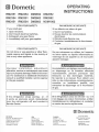
FOR YOUR SAFETY
lf you smell gas:
1. Open windows.
2. Don't touch electrical switches.
3. Extinguish any open flame.
4. lmmediately call your gas supplier.
FOR YOUR SAFETY
Do not store or use gasoline or other flammable vapors and liquids in the vicinity of
this or any other appliance.
lmproper installation, adjustment,
alteration, service or maintenance can cause
injury or property damage. Referto this manual. For assistance or additional information
consult a qualified installer, service agency
or the gas supplier.
OPERATING
INSTRUCTIONS
PAR MESURE DE SECUNITE
Si on d6tecte une odeur de gaz :
1. Ouvrir les fenOtres.
2. Ne pas toucher les commutateurs
6lectriques.
3. Eteindre toute flamme nue.
4. Contacter imm6diatement le fournisseur
de gaz.
PAR MESURE DE SECUNITE
Ne pas entreposer ou utiliser de l'essence
ou autre vapeur ou liquide inflammable au
voisinage de cet appareil ou de tout autre
appareil m6nager.
Une installation, un 169lage, une modification,
un d6pannage ou un entretien effectu6s
incorrectement, peuvent provoquer des
blessures ou des dommages mat6riels.
Se reporter i ce manuel. Pour obtenir une
aide ou des informations compl6mentaires,
consulter un installateur qualifi6, une
entreprise de d6pannage ou le fournisseur
de gaz.
lf the refrigerator stops cooling - or - if
it emits an ammonia smell, immediately
turn the refrigerator off and contact a
Service Center.
Si le r6frig6rateur cesse de refroidir - ou - s'il
s'en d6gage une odeur d'ammoniac, arr6ter
imm6diatement le r6frig6rateur et contacter
un centre de service aprds-vente.
@
REVISION
Form No. 3313240.016 6111
(Replaces 331 3240.000)
(French 3313241.013)
@2011 Dometic, LLC
LaGrange, lN 46761
USA
CANADA
Dometic, LLC
Service Office
Dometic, LLC
48 Zatonski, Unit 3
Brantford, ON N3T 518
CANADA
Phone: 51 9-720-9578
2320 lndustrial Pkwy.
Elkhart, lN 46516
Phone: 574-294-2511
Dometic
Corporate Office
2320 lndustrial Parkway
Elkhart, lN 46516
For Service Center
Assistance
Call: 800-544-4881
Thank you for purchasing a new Dometic refrigerator. This product is a recreational vehicle refrigerator intended for the storage of fresh and frozen foods, as well as making ice. Please read and be aware of possible safety hazards identified in this
manual, and become familiar with the alert symbols on the refrigerator. Read this manual carefully so that you know how to
operate the refrigerator safely and correctly. Keep this manual with the refrigerator for future reference.
REFRIGERATOROVERVIEW,,,,
INSTRUCTIONSFORUSE...
STORAGECOMPARTMENTS.
PRODUCTCARE.
MAINTENANCE&SERVICE..,.
REFRIGERATORREMOVAL.,.,,
TROUBLESHOOTING
APPENDIXA-SPAREPARTS
APPENDIXB-REARVIEWEQUIPMENT...
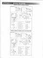
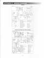
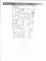
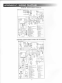
APPENDIXC-WIRING DIAGRAM
APPENDIXD-CONSUMERSUPPORT....
APPENDIXE-DOMETICWARRANTY
APPENDIXF-MAINTENANCESCHEDULE.
NOTES
.,,,,4
.....,,,.7
...10
..,,.,11
...,.13
..,,14
.,,....15
...
...16
...18
.,,20
,.,25
...,.,26
..,.,.,,27
,.,28
SYMBOLS
The following symbols are used throughout this manual:
A
This is the safety alert symbol. lt is used to alert you to personal injury hazards. Obey all safety
messages that follow this symbol to avoid possible injury or death.
WARNING indicates a hazardous situation which, if not avoided, could result in death or serious injury.
CAUTION, used with the safety alert symbol, indicates a hazardous situation which, if not avoided,
could result in minor or moderate injury.
NOTICE is used to address practices not related to personal injury.
@
[g
lnformation
Step-by-step instructions
ABSORPTION COOLING SYSTEM
WHEN THE REFRIGERATOR
f7\
N/
IN USE
When turning on the refrigerator, you should adjust the thermostat (excludes RM2351, RM2451,
RM2551 , DM2652 & DM2852 - not adjustable) to
the coldest temperature setting. The cooling cycle
may require an extended running time before cooling effect is observed.
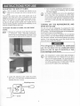
LEVELING THE REFRIGERATOR
Leveling is one of the requirements for proper gperation
with absorption refrigerators. To ensure proper leveling the
vehicle needs to be leveled so it is comfortable to live in
(no noticeable sloping of floor or walls).
Any time the vehicle is parked for several hours with the
refrigerator operating, the vehicle should be leveled to allow proper cooling.
When the vehicle is moving, the leveling is not critical, as
the rolling and pitching movement of the vehicle will pass
to either side of level, keeping the liquid ammonia from
accumulating in the evaporator tubing.
PURGING AIR FROM THE LINES
lf the refrigerator has not been used for a long time - or the LP tanks have just been refilled, air may be trapped in
the supply lines. To purge the air from the lines, turn the
refrigerator off and on by pressing the ON/OFF button. lf
the flame is not lit within 45 seconds, turn the refrigerator
off and back on again. This procedure can be repeated 3 to
4 times. lf repeated attempts fail to start the LP gas operation, check to make sure that the LP gas supply tanks are
not empty and that all manual shutoff valves in the lines
are open. lf the problem persists, turn the refrigerator off
and take it to a Service Center.
NOT
Any absorption refrigerator that is to be taken out of service for an extended period of time should be turned off.
/A
V/
lt is important that you do not leave the refrigerator
to run idle and/or unattended for days or weeks.
AUTOMATIC ENERGY SELECTOR
SYSTEM
The refrigerator is equipped with an automatic energy se-
lector system. The user tums the refrigerator on and then,
the refrigerator automatically selects the most suitable energy source available, either 120 VAC or LP gas operation.
The system can be set by the user to be fully automatic
(AUTO mode is selected) or to operate on LP gas only
(AUTO mode is off).
On 3-way models, the control system can manually be set
to DC mode (DC operation). The DC mode overrides all
other operating modes.
The refrigerator controls willwork down to 9.6 VDC.
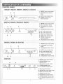
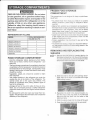
CONTROL PANEL
RM2351, RM2451, RM2551, DM2652 & DM2852
1. ON/OFF button (main power)
2. AUTO/GAS mode selector
AB
button
- ON
r.
A. AUTO mode indicator lamp
B. CHECK indicator lamp
AUTO
CD
OFF
(GAS mode only)
RM2354, RM2454, RM2554 & DM2663
1. ON/OFF button (main power)
2. DC mode selector button
3. AUTO/GAS mode selector
button
rON
r
)DC
COLD12345COLDEST
) AUTO
@ @
@ )AC
OFF
4. Temperature
selector button
A. DC mode indicator lamp
) GAS
B. AC mode indicator lamp
C. GAS mode indicator lamp
D. AUTO mode indicator lamp
E. CHECK indicator lamp
(GAS mode only)
F. Temperature indicator lamps
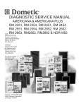
DM2662, DM2862 & NDM1062
1. ON/OFF button (main power)
2. AUTO/GAS mode selector
button
3. Temperature selector
-oN
) AUTO
r
) GAS
O
OFF
COLD12345COLDEST
@
button
A. AUTO mode indicator lamp
B. AC mode indicator lamp
C. GAS mode indicator lamp
D. CHECK indicator lamp
E. Temperature indicator lamps
1. ON/OFF button (main power)
2. AES/AUTO/GAS mode
selector button
Temperature selector button
coLD I
2 3 4
SCODEST
3.
4. Climate control button
5. Low ambient control button
A. AC mode indicator lamp
B. AES/AUTO mode indicator lamp
C. GAS mode indicator lamp
D. CHECK indicator lamp
E. Temperature indicator lamps
F. Climate control indicator lamp
G. Low ambient control indicator
lamp
l-
MODES OF OPERATION
AUTO MODE . AES/AUTO MODE
When operating in AUTO
-
AES/AUTO mode, the AUTO
- AES/AUTO mode indicator lamp is illuminated. The con-
trol system will automatically select between AC and GAS
operation. AC has priority over GAS. Should AC become
unavailable, the system automatically switches to GAS.
As soon as AC becomes available again, the control will
switch back to AC regardless of the status of the GAS
operation.
lf the CHECK indicator lamp is illuminated the controls
have failed to ignite the burner in the GAS mode. To restart an ignition attempt with the CHECK lamp illuminated
(or to turn off the CHECK lamp), press the ON/OFF button
OFF and back ON again. The control system activates
the ignition system and makes three attempts to light the
burner for a period of approximately 45 seconds at two
minutes interval. Should 120 VAC become available while
the CHECK indicator lamp is on, the CHECK lamp will nof
turn off until the ON/OFF button is pressed OFF and then
ON again.
GAS MODE
RM2351, RM2451, RM2551, DM2652 & DM2852:
When operating in GAS mode, the AUTO mode indicator
lamp will be off.
RM2354, RM2454, RM2554, DM2662, DM2663, DM2862 &
NDM1062: When operating in GAS mode, the GAS Mode
indictor lamp is illuminated.
This mode provides LP gas only. The control system activates the ignition system and attempts to light the burner
for a period of approximately 45 seconds at two minutes
interval. lf unsuccessful, the CHECK indicator lamp will
illuminate.
To restart GAS operation, press the ON/OFF button to
OFF and then back ON. The control system attempts a
new ignition sequence.
DC MODE
RM2354, RM2454, RM2554 & DM2663
When operating in DC mode (3-way models only), the DC
mode indicator lamp is illuminated and all other lamps
are off. To select another operating mode, turn off the DC
mode by pressing the DC selector button. The DC lamp
is turned off.
When there is no charging of the house battery, switch to
AUTO mode or GAS mode since runni ng the refrigerator on
12VDC will quickly drain the battery.
LIMP MODE OF OPERATION
ln the event of a failure of a major operating component,
the control system will continue to operate the cooling
system.
RM2351, RM2451, RM2551, DM2652 & DM2852
lf the control can not read the temperature sensor and
control the preset temperature, the control will run the
cooling unit continuously at the energy source available.
The refrigerator will continue to operate in this mode indefinitely - or - until a new sensor is installed and the sys-
tem reset.
RM2354, RM2454, RM2554, DM2662, DM2663, DM2862 &
NDM1062
Two modes of operation can occur:
'1)The first limp mode of operation will execute if the
display module becomes non functional. The control
system reverts to full automatic operation selecting
the best energy source available with AC, DC (3way only) and GAS priority. The temperature setting
is maintained at the mid position. The power module
will continually attempt to reestablish operation of the
display module.
2) The second limp mode of operation will execute when
a failure of the temperature sensing device or associated electronic circuitry occurs. lf this should happen,
the control system operates on the energy source selected via the control panel. The cooling unit runs continuously on the selected energy source. The refrigerator continues to operate in this mode indefinitely or
until a new sensor is installed and the system is reset.
THE REFRIGERATOR
FIRE HMARD. When the RV has not been
used for some time, make sure that the path
between the burner jet and the burner tube
has not been obstructed before lighting the
LP gas burner. Failure to obey this warning
could cause a fire resutting in death or serious injury.
FIRE OR EXPLOSION HMARD. When refueting or parked near gasoline pumps shut off ail
LP gas appliances. Failure to obey this warning could cause a fire or explosion resulting
in death or serious injury
LP GAS EQUIPMENT ASSEMBLY
- DC mode (3-way models only)
Press the DC mode indicator button. The DC
lamp will be turned on. To selectAUTO or GAS
mode, turn off the DC mode by pressing the
DC mode selector button. The DC lamp will
then be turned off.
ADJ USTING THE THERMOSTAT
R1t2354, RM 2454, RM2554, DM2662, DM2663, DM2g62
& NDM1062
The thermostat controls both the gas and electric operation. thereby eliminating the necessity of resetting each
time a difierent energy source is employed. After the initial
start-up, the thermostat should be adjusted to the desired
temperature setting.
11A 1. Press the temperature selector button until the
lamp at the debired setting is illuminated.
Rf,t2351, RM2451, RM2551, DM2652 & DM2g52
The temperature is controlled by a factory preset temperature setting.
--'E'
COLD WEATHER LOW
AMBTENT
CONTROL
NDM1062
The refrigerator is equipped with an exclusive feature that
allows for trouble-free operation in low ambient temperature (like below 50"F) for extended periods of time. Once
the outdoor temperature is above 50.F, the low ambient
switch should be turned off.
'1. Turn the Low ambient control
switch to I (ON).
[g
1. Check that all the manual gas valves are in the
1|F
' .E' oN position.
2. Make sure that a continuous 12 VDC supply
The Low ambient control
switch is located beneath
the top decoration panel
that houses the control
panel.
is
available for the electronic control to function.
3. Press the ON/OFF button.
4. Select operation mode:
- AUTO -AES/AUTO mode (AC and Gas)
Press the AUTO/GAS - AES/AUTO/Gas mode
selector button (if not already on). The illuminated lamp indicates the selected mode.
(lf the CHECK indicator lamp is illuminated,
see REFRIGERATOR OVERVTEW > MODES
OF OPERATION > AUTO MODE - AES/AUTO
MODE for further information.)
-
GAS mode (LP gas operation
only)
Press the AUTO/GAS - AES/AUTO/Gas mode
selector button to turn off the AUTO mode (if
not already off).
(Within 45 seconds the burner should be ignited and operating normally. lf not, see REFRIGERATOR OVERVIEW > MODES OF
OPERATION > GAS MODE for further information.)
2. Press the LAC button. The indicator lamp will
illuminate.
EXTREME COLD WEATHER
OPERATION
OPERATING THE ICE MAKER
Refrigerator performance may be reduced in extremely
cold (subzero) temperatures. This temporary condition is
normal for absorption refrigerators and does not indicate
product failure. ln the event that performance is reduced
in such conditions, turn the refrigerator off. As ambient
Before the ice maker can operate, make sure that:
. The refrigerator is connected to 120 VAC .
. The water valve supplying the refrigerator is turned on.
. The ice level bail arm is in its fully down position.
NDM1062 WITH ICE MAKER
lce level
temperatures rise, please restart your refrigerator according to instructions before requesting service.
bailarm
CLIMATE CONTROL SYSTEM
NDM1062
During the summer months of high temperature and
humidity, the metal frame between the freezer and fresh
food compartments may have water droplets forming. The
numberof water droplets will increase if the vehicle is not air
conditioned during these months. The refrigerator comes
standard with a 12 VDC climate control that will evaporate
the water droplets when they form. The climate control can
be left on continuously or used only when temperatures
require it. Note that when turned on, the climate control
will draw 12VDC power continuously. Turn it off when a
charging source is not available.
1. Turn the climate control switch to I (ON).
[g
The Climate control
switch is located beneath the top decoration panel that houses
the control panel.
2. Press the CLC button. The indicator lamp will
illuminate.
When the ice makerthermostat senses the presettemperature for the ejection of the ice cubes, the fingers will start to
rotate, dumping any ice cubes and filling the mold with water.
When the storage container is full, the bail arm will come
in contact with the ice cubes. The bail arm cannot return
to the full down position and the ice production is stopped
untilthe bin is emptied, or ice cubes are removed.
To prevent water from splashing out of the mold assembly
while travelling in your recreational vehicle, raise the bail
arm to the full UP/OFF position aboul l-112 hours before
departing. This will allow the water in the mold to freeze.
WATER SUPPLY
The water supply system must have a minimum pressure
of 15 pounds per square inch gauge (psig). 4114" diameter water line to the water valve should be used at the rear
of the refrigerator. The water line must have a manual
shutoff valve placed where it is easily accessible.
The maximum water level is represented by a thin line. lt
is essential that the water level does not exceed this line!
lf necessary,change the water flow by adjusting the water
supply. For instructions, see ADJUSTING THE SIZE OF
CUBES.
3. Turn the screw clockwise to decrease the cube
size or if the mold is overfilling, and the cubes
ADJUSTING THE SIZE OF CUBES
A,
q/
lf the ice maker was cleaned and drained, no ice
cubes will be dumped into the bin during the first
cycle.
The first few cycles may have small cubes due to air
trapped in the water lines. The first container of ice cubes
should be dumped if the water system has been winterized or not used for several weeks. Once the ice maker has run through several cycles and if cubes are too
small or sticking together, adjustment is necessary on the
amount of water entering the mold.
TO ADJUST THE SIZE OF CUBES, FOLLOW THESE
STEPS:
r3F
rEa
1. Remove the protective cover from the ice maker mechanism. Using a flat-head screwdriver,
place the tip of the screwdriver in the slot. Twist
the screwdriver blade gently to loosen the cover.
are stuck together.
/A
K/
To prevent overfilling, do not turn the adjustment
screw more than one revolution at a time. Allow
the ice maker to cycle several times before another
adjustment is made. Be sure to replace the protective cover on the cycle after the adjustments are
complete.
TURNING OFF THE REFRIGERATOR, AND
WHEN NOT IN USE
You can turn off your refrigerator by pressing the main
power ON/OFF button found on the control panel to the
OFF position. This will shut off all power to the refrigerator,
induding DC power to the refrigerator.
lf the refrigerator will not be in operation for an extended
period of time or put into winter storage it should be emptied, defrosted, cleaned, and the doors placed in the airing
position. lf ice cube trays are in use, they should also be
dried and kept outside the cabinet.
This refrigerator is intended for continuous
use. Do not allow it to run unattended when
there is a risk for loss of electricity or fuel.
Food sDoilaqe could occur.
f-\
K/
the adjusting screw under the protective cover. Turn the screw counterclockwise to
2. Locate
increase the size of cubes.
Adjusting screw
+-
Cover
The refriqerator's control system still consumes a
few milliJmps even if it is turned off. lf your RV is
being put into winter storage, it is recommended to
either put your RV batteries on a battery charger or
turn off the vehicle's main 12 VDC switch. This will
prevent the RV battery from discharging.
3
FROZEN FOOD STORAGE
COMPARTMENT
FIRE OR EXPLOSION HAZARD. Do not store
or use gasoline, oil or gasoline soaked rags,
or other flammable vapors and liquids in the
service area behind the refrigerator or in the
This compartment is not designed for deep or quick freezing of food.
. To prevent food from drying out, keep
vicinity of this or any other gas appliance.
Failure to obey this warning could cause a
num foil.
the frozen food storage compartment provided they are
precooled first in the refrigerator. They can be stored
about three times longer in the frozen food compartment as compared to the fresh food compartment.
. Quick frozen soft fruits and ice cream should be placed
in the coldest part of the compartment, which is at the
bottom of the aluminum liner.
. Frozen vegetables, may be stored in any part of the
compartment.
. To prevent frost buildup, whieh can reduce the efficiency, wipe excess moisture off items being placed in the
compartment.
REFRIGERATOR VOLUME
TOTAL REFRIGERATED
voLUME (CU.FT)
RM235l& RM2354
.,
RM2451& P.M2454
4
RM2551 & RM2554
5
DM2652,DM2662 &D}d2663
6
DM2852 &DM2862
8
NDMI062
9.2
covered
. Meat or fish, whether raw or prepared, can be stored in
fire or an explosion resulting in death or seri-
MODEL
it in
dishes, containers, plastic bags or wrapped in alumi-
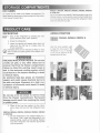
REMOVING AND REPLACING THE
SHELVES
Remove the shelf locks by inserting the tip of a
ff$
E\:€' 1. flat
bladed screwdriver intb the slotlf the iocks.
FOOD STORAGE COMPARTMENT
Turn the screwdriver counterclockwise and then
remove the shelf locks from the wire shelf.
. Cool the refrigerator before placing any food inside.
Never put hot food or drinks into the refrigerator - cool
them first.
. The food storage compartment is completely closed and
unventilated, which is necessaryto maintain the required
low temperature for food storage. Consequently, foods
having a strong odor or those that absorb odors easily
should be covered.
. Vegetables, salads, etc. should be covered to retain
their crispness.
. The coldest positions in the refrigerator are under the
cooling fins and at the bottom of the refrigerator. The
warmer areas are on the upper door shelves. This
Slide the shelf to the left until bushings disengage, then tilt the shelf to one side at an angle
while pulling fonvard.
should be considered when placing different types of
food in the refrigerator.
. Arrange all food in the unit to allow for free air circulation. Do not overpack because a stuffed refrigerator
must work harder and will have higher cabinet temperatures.
. Do not leave the unit's door open any longer than necessary. This will reduce frost formation and increase the
efficiency of the refrigerator.
3. Reposition the shelf in the desired location. lnsert the ends of the wire shelf on the left-hand
side and slide the shelf into the holes on the
right-hand side.
4. Slide the plastic plugs into the holes of the wall.
5. Snap the shelf locks back onto the wire shelf.
10
ICE CUBES
lce cubes can be made in the freezer compartment. For
faster freezing, place trays in direct contact with the bottom
of the freezer compartment.
RM2351, RM2454, RM2554, DM2662, DM2663, DM2862
& NDM1062
lce will be made more rapidly if the thermostat is set at its
highest position, but be sure to move the thermostat back
to normal setting when ice is formed; the refrigerator might
othenvise become too cold.
DEFROSTING
fiF
^v
1. Shut off the refrigerator by pressing the main
power ON/OFF button (OFF position).
2. Empty the refrigerator.
3. Leave the cabinet and freezer doors open and
make sure the drip tray is in place under the
5
\/
finned evaporator.
Defrosting time can be reduced by filling ice trays
with hot water and placing them in the freezer compafiment.
AIRING POSITION
DM2652, DM2662, DM2663, DM2852 &
DM2862
Use the airing position card
to keep the doors ajar if the
refrigerator is put in storage
or will not be used for an extended period of time.
FIRE AND INHALATION HAZARD. Do not use
a knife, ice pick, or any other sharp tool to
remove frost from the freezer compartment.
Failure to obey this warning could cause a
leak in the ammonia cooling system which
could lead to a fire hazard resulting in death
or serious injury.
An ammonia leak also poses an inhalation
hazard, and could cause chemical burns to
the skin and eyes. Exposure to a high con'
centration of ammonia could result in death
or serious injury.
Do not use a hot air blower to remove frost
from the freezer compartment. Permanent
damage could result from warping the metal
or plastic parts.
4. When all the frost has melted, dry the interior
with a clean cloth and turn the refrigerator back
on.
RM2354, RM2454, RM2554, DM2662, DM2663, DM2862
& NDM1062
5. Set the thermostat to the coldest setting for a
few hours. Then, reset the thermostat to the
desired setting, usually at mid setting. Replace
food after refrigerator has reached appropriate
cool temperature.
:
&
L
CLEANING
Always keep the refrigerator clean' Cleaning the refrigerator is usually done after it is defrosted or put into storage'
interior
Use a lukewarm, weak soda solution to clean the
the
clean
to
only
liner of the refrigerator. Use warm water
liqspray
not
Do
finned evaporator, gasket, and shelves'
refrigerator
the
or
uids near electrical outlets, connections,
components.
STORAGE PROCEDURE /WINTERIZ.
ING THE REFRIGERATOR
NDM1062 WITH ICE MAKER
The refrigerator is equipped with a heater tape wrapped
around tf,e water solenoid valve and outlet water tube'
During cold weather operation below 32'Fl0"C the auon
tomatic temperature switch will turn the heater tape
automaticallY.
time
lf the RV will not be in use for an extended period of
or put into storage:
. Drain the RV water sYstem'
. Disconnect the water lines from the inlet and outlet
sides of the water valve. Drain the lines into a cup and
allow the lines to dry.
. The ice maker should be drained and dried' Note that
this procedure must be performed by a qualified ser-
Do not use strong chemicals or-abrasives to
&ilah"se parts] as the protective surfaces
will be damaged.
periodic inTo keep the refrigerator operating efficiently,
a year
spection and cleaning of several components once
is recommended:
. Check the lower vent, upper vent and area between
these openings for any obstructions such as bird/insect
vice technician.
. Using
a lukewarm soda solution, clean the
interior
tiner-of the refrigerator. Clean the finned evaporator
and shelves. Use warm water only and never strong
chemicals or abrasives since these can damage the
nests, sPider webs, etc.
. Make sure the refrigerator area is free from combustimaterial, gasoline and other flammable vapors or
ble
protective surfaces.
liquids.
. Place doors in the airing position'
FIRE OR EXPLOSION HAZARD' Do not store
or use gasoline, oil or gasoline soaked rags'
or othei flammable vapors and liquids in the
service area behind the refrigerator or in the
vicinity of this or any other gas appliance'
Failure to obey this warning could Gause a
fire or an explosion resulting in death or seri'
ous iniury.
. lf accessible, clean the coils on the back of the refrigthe coils'
erator. Use a soft bristled brush to dust off
12
3. Replace the fuse.
inspect the connections, the control system, the LP
gas pressure and flue baffle.
FIRE AND INHALATION HAZARD. lf the refrigeratorstops working -or- if it emits an ammonia smel!, immediately turn the refrigerator
off, leave the vicinity, and contact a Seryice
Center.
4. Put the holder back together.
A high concentration of ammonia refrigerant could cause an inhalation hazard, could
cause chemical burns to the skin and eyes,
and could cause a fire resulting in death or
serious injury.
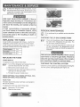
PERIODIC MAINTENANCE
@ Jl,f"
CHECKING THE LP GAS CONNEGTIONS
REPLACING THE FUSES
[fA
2-way models are equipped with 2 fuses - one for the
refrigerator control system and one for the AC heater.
AC heabr
12 VDC heater
3A
5A
30A
FIRE OR EXPLOSION HAZARD. Never use an
open flame to check for gas leaks. Failure to
obey this warning could cause a fire or explosion resulting in death or serious
REPLACING THE FUSES
POWER MODULE
To replace the fuses, follow these steps:
ITF
--v
1. Check all connections in the LP gas system (at
the back of the refrigerator) for gas leaks. The
LP gas supply must be turned on.
2. Apply an approved leak detection solution to all
LP gas connections. The appearance of bubbles indicates a leak and should be repaired immediately!
3-way models are equipped with 3 fuses - two fuses in
the power module and one in-line blade fuse.
Gontrolsvstem
o"normed by a qualified service technician
CHECKING THE CONTROL SYSTEM
1. Turn off the refrigerator and unplug the power
cord and disconnect the 12V wires.
2. Remove the power module cover.
3. Snap the fuse out of the fuse holder and fit the
new fuse in to the fuse holder.
4. Put back the power module cover.
Check the control system by connecting/disconnecting the
120 VAC power, starting/stopping the engine, etc.
DM2652 (OPTIONAL FAN), DM28s2 (OPTIONAL FAN),
DM2862 (OPTTONAL FAN) & NDM1062
INLINE FUSE
The inline fuse for the power vent fans is connected to
the 12V DC socket.
To replace the inline fuse, follow these steps:
1. Disconnect 12V DC power.
2. Open the fuse holder.
13
7. Be sure to check the burner flame for proper ap-
CLEANING THE BURNER
pearance. The flame should be clear blue over
the slots of the burner.
1. Turn off the refrigerator
2. Unplug the power cord from the 120 VAC outlet. Disconnect the wires or shut off the 12 VDC
power supply to the refrigerator.
3. Turn off the manual shut off valve.
4. Remove cover from burner housing.
Clear Blue Color
Of Flame
5. Clean the burner tube with a brush. Blow out the
burner with compressed air.
8. Check the electrode for proper location and gap.
Adjustments may be made with needle nose pliers if necessary.
FIRE HAZARD. Never use a wire or pin to clear
obstructions from the burner iet as damage
will occur. Do not attempt to adjust the burner
jet. Failure to obey this warning could cause
a fire resulting in death or serious injury.
Electrode
rYq\
l'@pl
1/8" to 3/16"
(3-5 mm)
ft
Burner Tube
9. Turn on the manual gas shut off valve.
10. Examine all fittings for leaks. Use a commercial
non-corrosive bubble solution.
11. Connect the 120 VAC power cord.
6. Verify that the burner jet slots are centered un-
12. ReconnecUTurn on the 12VDC power.
13. Check LP gas safety shutoff.
der the flue tube.
f.\
K/
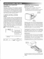
To replace the refrigerator:
Refrioerator removal and installation should be
perfoimed by a qualified service technician.
sure the sealing strips (isolating the apftF
IP\E'1. Make
pliance combustion system from the vehicle
interior) are properly positioned for a complete
Before removing the refrigerator:
1. Verify that the 120 VAC power cord is disconnected at the rear of the refrigerator.
2. Verify that the 12VDC leads are disconnected
and capped at the rear of the refrigerator.
3. Shut off the gas supply.
4. Disconnect and cap the LP gas line at rear of
refrigerator.
seal.
rrF
r}rg
2. Slide the refrigerator back into the compart-
ment.
3. Replace the screws anchoring the refrigerator
to the enclosure.
4. Reconnect the LP gas supply line at the rear of
the refrigerator.
Always use a backup wrench when loosing
and tightening LP gas connections.
Always use a backup wrench when loosing
and tightening LP gas connections.
5. Check all connections for LP gas leaks.
6. Reconnect the 12 VDC leads at rear of refrig-
To remove the refrigerator:
lTF'1.
r -.,'
Remove the screws anchoring the refrigerator
to the enclosure.
2. Slide the refrigerator out of the compartment.
erator.
7. Reconnect the 120 VAC power cord at rear of
refrigerator.
14
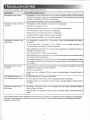
lf you run into a problem, refer to the troubleshooting table below.
Symptofi
Refrigerator stops cooling.
Refrigerator emits an ammonia smell
Gheck/Remedial action
. lmmediately tum the refrigerator off and contact a Dometic dealer or Service Center.
NOTE! Do not leave it running for an extended period of time, and never try to solve the
problem by repeatedly restarting the refrigerator.
. Do not use the refrigerator until it has been repaired
. lmmediately turn the refrigerator ofi at the front control panel.
. Do NOT open refrigerator doors.
. Open coach windows and doors (to air out the coach) and evacuate.
. Turn off manual LP gas valve at rear of refrigerator.
. Disconnect the 120 VAC power at rear of refrigerator.
. Contact a Dometic dealer or Service Center for repair.
. Do not use the refrigerator until it has been repaired.
Refrigerator or freezer is not
cold enough
. For refrigerators equipped with a thermostat, check the thermostat and adjust if
necessary.
.ls the plug firmly connected to the socket? ls the socket switched on?
Check the socket by plugging in another appliance.
. ls the refrigerator level? (Due to the nature of its operation it is important to keep an
absorption refrigerator level.
)
. Door closing properly? Check the door gasket.
. Heavy frost build-up on evaporator fins? To prevent frost build-up do not leave the unit's
door open longer than necessary.
. Over packed refrigerator? The unit will have to work harder if the refrigerator is stuffed,
and results in higher cabinet temperatures. Arrange the food in the unit to allow for free
air circulation.
Refrigerator does not work
on electric
. ls the plug firmly connected to the receptacle? ls the receptacle energized? Check the
receptacle by plugging in another appliance.
. ls there a power failure?
. Blown fuse. Tum refrigerator off and contact a Dometic dealer or Service Center for
repair.
The refrigerator does not
work in gas operation mode
. LP gas bottle empty? Change the gas bottle.
. Air in the gas line? Remove the air by repeating the ignition sequence.
. lf problem resists, tum refrigerator off and contact a Dometic dealer or Service Center
for repair.
Refrigerator emits an odor
from fumes:
. Dislocated or damaged bumer. Tum refrigerator off and contact a Dometic dealer or
Service Center for repair.
. Dirty flue tube. Turn refrigerator off and contact a Dometic dealer or Service Center for
repair.
lf the problem persists and the refrigerator is still not working properly, turn refrigerator off and contact your nearest Service Center. State the problem, model, product, and serial number. These details are stated on the data label inside the
refrigerator compartment.
15
MODEL
RM2351
RM2354
RM2451
RM2454
RM2551
RM2554
DM2652
SPARE PARTS
N/A
N/A
N/A
N/A
N/A
N/A
3312S86 403
Baffle
2007172022
2007172022
2932667013
2932667013
2932667021
2932667021
2932667039
Box
293263601
Airing position card
29326360't8
N/A
N/A
N/A
NiA
N/A
Box, vegetable
NiA
N/A
N/A
N/A
2932621010
2932621010
2932621010
Box, vegetable
(crisper), 2 pieces
N/A
N/A
N/A
N/A
NiA
N.]A
N/A
Box, vegetable
(meat locker)
N/A
N/A
N/A
N/A
N/A
N.A
N/A
Burner
(with conductor)
2930697079
2930697079
2930697079
2930697079
Door reversing kit,
(light brown)
38503040'1
385030401
NiA
N/A
N/A
NA
N/A
Door reversing kit,
(black)
385030402
385030402
N/A
N/A
N/A
NA
N/A
Door reversing kit,
right-left (light brown)
N/A
N/A
293275002
293275002
293275002
293275002
293275008
Door reversing kit,
left-right (light brown)
N/A
N/A
293275003
293275003
293275003
293275003
293275009
Door reversing kit,
right-left (black)
N/A
N/A
293275013
293275013
293275013
293275013
293275011
Door reversing kit,
left-right (black)
N/A
N/A
293275014
293275014
293275014
293275014
293275012
Door shelf, lower
N/A
N/A
2932575018
2932575018
2932575018 2932575018
2932575018
Door shelf, (2 pieces)
N/A
N/A
2932576016
2932576016
2002261242
2002261242
N/A
N/A
N/A
N/A
N/A
2932781012
2932781012
2932781012
2932781012
Halogen lamp
(12V 10W base G4)
N/A
N/A
N/A
N/A
Handle (black)
N/A
N/A
2932670025
2932670025
Heater 175W, 12V
N/A
38506461 04
N/A
38506461 04
Heater 175W, 120V
3850644455
3850644455
3850644455
3850644455
Heater 275W, 12V
N/A
N/A
N/A
N/A
N/A
NiA
N/A
Heater 325W, 120V
N/A
N/A
N/A
N/A
N/A
Nr'A
3850644422
Door shelf, (3 pieces)
Door shelf, freezer
Electrode
B
16
N/A
2930697079 2930697079 2930697079
N/A
NA
2932576016 2932576016
N/A
NrA
2932781012 2932781012
N/A
N]A
2932670025 2932670025
N/A
2932576016
N/A
2932577014
2932781012
N/A
3851174023
3850646104
N/A
3850644455 3850644455
N/A
Xo='\
DM2662
DM2663
oM2852
DM2862
NDM1062
Airing position card
331 2986.403
331 2986.403
331 2986.403
331 2986.403
N/A
Baffle
2932667039
2932667039
2932667047
2932667047
2932667047
N/A
N/A
N/A
N/A
N/A
2932621077
2932621077
2932621010
2932621077
N/A
Box, vegetable
(crisper), 2 pieces
N/A
N/A
N/A
N/A
2002726178
Box, vegetable
(meat locker)
N/A
N/A
N/A
N/A
293262108s
Burner
(with conductor)
2930697079
2930697079
2930697079
2930697079
2930697079
Door reversing kit,
(light brown)
NiA
N/A
N/A
N/A
N/A
Door reversing kit,
(black)
N/A
N/A
N/A
N/A
N/A
Door reversing kit,
right-left (light brown)
N/A
N/A
293275008
N/A
N/A
Door reversing kit,
left-right (light brown)
N/A
N/A
293275009
N/A
N/A
293275011
293275011
293275011
293275011
293275011
2932750't2
293275012
293275012
293275012
293275012
2932575018, 2932575059
2932575075
SPAREPARTS
Box
Box, vegetable
Door reversing kit,
rightleft (black)
Door reversing kit,
left-right (black)
,
Door shelf, lower
2932575059
2932575059
Door shelf, (2 pieces)
2932576065
2932576065
Door shelf, (3 pieces)
N/A
N/A
2932576016
Door shelf, freezer
N/A
N/A
2932577014
2932781012
2932781012
N/A
N/A
3851174023
3851174023
Electrode
Halogen lamp
(12V 10W base G4)
Handle (black)
N/A
N/A
N/A
2932576065
2932576081
N/A
2932781012 2932781012
N/A
N/A
3851174023, 3851174023
N/A
2932781012
385045501
I
2932094044
Heater 175W, 12V
N/A
N/A
N/A
N/A
N/A
Heater 175W, 120V
N/A
N/A
N/A
NiA
N/A
Healer 275W, 12Y
N/A
3850646096
N/A
N/A
N/A
3850644422
3850644422
3850644422
3850614422
3850644422
Heater 325W, 120V
17
RM2351 & RM2s54
t heater - RM2351
2 heaters - RM2354
Power module
cover
12V DC
Terminal block
RM2451, RM2454, RM2551 & RM2554
18
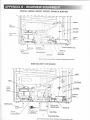
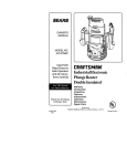
DM2652, DM2662, DM2663, DM2g52, DM2g62 & NDM1062
Power module
Shown without Secondary Burner Housingfor illustrative parposes only,
NDM1062 W|TH tCE MAKER)
Thermofuse
Flue Baffle
Protection
Flexible Cord
Manual Gas
Valve
12V DC
Terminal Block
Flexible Cord
Drain Water Hose
Shown without Secondary Burner Housing
for illastative purposes only.
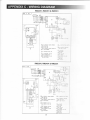
RM2351, RM2451 & RM2551
385't1
51
ortO-OP{:
@
tlto
L-
GROUilO
@:- cIncuIT
FUSE 3A
^(9F FUs E sA
(!}_
EoARD
cInculT
BoAHD
^(9,)- ELECTR0DE
(9r--
POWER
@- xelre n r zov rc
O:^(t!}
(!ti-
TERMINAL BLocK
THERMISToR
s0LEN0rD vALvE
(UF NETAINER
RM2354, RM2454 & RM2554
385 11
52
@_ ctncurr BoARD PovtER
FUSE 3A
^(tF
Q)- FUSE 5A
CTRCUTT B0ARD DTSPLAY
^(9F ELEcTRoDE
(rFO=-
HEATER
12v
(f
AC
reRurrrl alocx
THERMTST0R
s0LEN0I0 vALvE
^(UF nerrv
(UF RETAINER
PR oTE
c: : , E : r : -
crnss;s or:-r:
@(t1). FUsE 3o^
(D1
1Es1 por,,-
Dc
(!rF HEATER 120v
^@
(!rF-
@-
alncx
@(21
BRorN
a--\i,_ HEU
YELLotY
^(1|
(tF- GBEEN
oneellverlow
^(9t BLUE
(r+
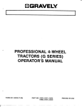
DM2652, DM2662, DM2852 & DM2862
DM2652, DM2852 & DM2862 (W|TH OpTtoNAL FAN)
@-
crnculr
(BF FUSE
BoARo powEF
3A
(c)- FUsF 5a
-@ crncurr BoAFD
(E>- ELEcTBoDE
l@
Q)(n!
DIspLAy
rnr*rorrs,
cressrs nouro
@(TF TEsr porNT
rrrnuoruse
@l(vF FAN
@1 ruse se
e
(!F
THERMAL FUSE
LATP
s*trcs Lnup
uerrrn reov ec
@1
(x! ueerllc cler r
rrnulnnr
erocr
@lrxtnursron
^@! s0LEN0rD VALVE
QrlFETAINER
-QiF PRoTEcTIVE EABTH
(PF
@(2F
\J_
-G!
GE
-@)
er-ecx
BRo!1/N
HEU
velrow
GREEN
onrrrTvrlrow
@tLue
(8F
@1 wurre
GREY
DM2663
385 14
83
+
::
ai
3-
_-.
?
-::\-=
':-
;i-:l:=:
@
€o
clacrrt BoAFD PowER
@_
(8F FUSE 3A
fif- psss 51
-@crncurr BoAFD DIsptAy
(9+ ELECTR0DE
_ e> THEF[,loFUSE
(c)rAMp
"G) swrrcr rnu,
uearrR rzv oc
@1
(KF
HEATER 12OV Ac
@1 rearlro
^(DF
0F^(9ts
(P}(R}
ceare
TEBMTNAL BL0CK
(r)-
(
sLAC
(3F_ FED
(aI YEt-:i
G)l cn::r
:i
THEBMTST0R
7)-- BIri
f al cnE!
Q)- sHr;:
s0LEN0rD vALVE
f
RELAY
FETAINEB
NDM1062 (STATNLESS STEEL DOORS)
@
@
8.8
;
crncurr
@(BF
(CI-
BoABD powEB
(sF cl-rss:-.
-(6! crncurr
BoABD DTsPLAY
rrecrnooe
fr.(FFLAMP
(G}-_ SWITCH
{v-
LAMP
120v
AC
(J^LLFHEATEB
HEATING CABI F
-fi! rerrrro, ,,0.*
(L}(MF
(N)--
"6>
(!)-
G}- pa:-::-:,
FUSE 3A
FUSF 54
THERMISTOR
THERMOFUSE
FANs
rorrroro ,^ru,
FETATNER
22
(UF TH!F!::.
FLrsF !r
@ rnrrr'-
fil-
B
rAC
r
(2F BF0*r,
(3)--
(4F
(5)(6}
6E-
(8F
@1
RED
YELLOS
GFEEN
GREEN
BLUE
GFEY
wrire
\:
NDM1O62 (STAINLESS STEEL OOONS A
,a.aB
ICEffi)
rnorecrrvr
@gF
crAssrs
_
r:s,!Ay @I-
tntrt
cqouND
TcEMAKEH
vlATEB vALvE
TEeVTNAT sLocK
(@F HELAy
GF HEATING CABLE
^@F
qg+
(AF> THEBMosTAT
-
@1
ruse
ft)-
-6).
srrcx
ron*"
f3)-
BFD
^A,l
(7)-
GBEEN/YELLoW
BLUE
@i-
wurrr
-G! rrr,o"
f nt"'
-@)
23
aa
onrv
NDM1062 (DOOR INSERT PANELS)
rnorecrtvr :0.-'
6)cTHCUIT
(BL FUSE 3A
BoABD PowEB
16E rusr sr
-(6! crncurr BoAFD
GE:rrctnoor
_(e)ts
(9-
(H}
DISPLAY
LAMP
SWITCH LAMP
HEATEB 12OV
AC
cnsur
@(K} rerrrrc
TEBMlTAL
f,Y-
^(I)F
(9-
(O}
SLOCK
THEnMIsToB
rHEnil0FUsE
FANS
SOTENOID VALVE
/FE nrrrrrrn
(D THEBMAL FUSE
^@ SWITCH
rTL
filLswrrcH L.a.c
(w)- THEn[0FUSE
(x.)- cHAssls GRo!r:
(YF FUSE 3A
(,F TEST POITT
(1](2)-
arlcr
BRowN
@neo
(4F YELLOW
r5L GFEET
r6L Gf,EEN]YEL.:t
6E erur
(8} GREY
ffwnrrr
NDM1062 (DOOR INSERT PANELS & ICE MAKER)
@- craculr
FUSE 3A
^e> FUsE sA
(9J-
soARD PosER
rNts CIFCUIT BOAFD DlSPLAY
6E
-@
rrecrnooe
Q):_
SWITCH LAUP
HEATEB 1 20v AC
HEATING CABLE
^(rF
rJT
-@
(LF
^QtF
reue
renurno, srocr
THERilISTON
THEEil0FUSE
"61 sorrrolo
(iE- nerrrrrn
THERMAL
verre
FUSE
-e> PFoTEcTIvE
Gt(IF
EARTH
SWITCH
rDEswrrcn r,e,c
(!iF
rHER{0FUSE
iD
Ctic,$6bsite.,,i;r.i'l
rriitr,.,i.r,',,',.
Please visit the website for information and news about Dometic products, you
contact, learn about product care, download manuals, leaflets and warranties.
rtorvice- andr sp-afeir$a''iri.l,,ir,.i;:l
For service, please contact the Service CenterAssistance,
to find the location of the nearest Dometic Service Center.
commonly used spare parts are listed in this manual, see APPENDtx A spARE PARTS. These should be available from
your Dometic Service Center.
':
GO'ntect, Us:i i1,:.i1.i.;.;'.i.irii;,r:.i1;ii,..r1ir.i,.:tl.t
For contact information, please see the front page of this manual - or - visit
the Dometic website.
,,.,,{rl{iitili
Raglcter,thi. piiandg.,r., ir,ilrtlrr'r,r.,
: ".'
fi[[
Timely registration will allow for enhanced communication and service
under the terms of the warranty, see Appendix E
Dometic warranty.
To register the appliance, fill in the pre-printed registration card on
the last page of this manual or register on-line at the
Dometic website www.edometic.com.
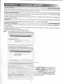
TO REGISTER ON.LINE, FOLLOW THESE STEPS:
At www.edometic,com, click \&arrantv Registration
&iiiwM
&*o- *. A!*& i.)'*a,$tthw & [t.li;h a,
2. ClickRegister your
f&
E* ve
FMr*
&o,' ri;
rd
ne\ry
Dometic product here.
*p
i$:'A {;;
i,**
"a:r,*r,
*
g
3
complete the information and then, click the submit Registration button.
:::---rgtl
=1''1
1o*'*;r;-';:,;.;.1,.*,6,11.;*'6.;;'*,' ,'
&!ri!aiq ,r* n* ln&il
n u $sernnt
*e
!r .ntu.
d, y* ..,,n!.
A ,t &r bede rd
.x.etr.fr.a$.,h!r's.!,iio,idht.tcsillkqyr*6rir&.lidiyTti!r.s,;bdrt
&n.,
.
,. *
r,,*i
ib,
.r.r'':,,"::r:rri:.ii_1r.i!;:.:1,"f,:ii:.':":.ij:i.:,;.i'..
.,iuri
,, ie i
,OrE?tr,Drc
t,,tgia;;,ilr.
'.'
]]E
io4, or iE.iE^noi^L irrrcla
r
.
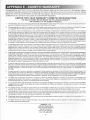
The model number (e.g. DM2662) and serial number
(e.9. 012 34567) are stated on the data tabet in the
refrigerator compartment.
25
Congratulations, and Thank You for purchasing the industry's best built and best backed RV Refrigerator. Below
you willfind importantwarranty and maintenance information on Dometic's exclusive two (2)yearwarranty. Please
take a few moments and familiarize yourself with the program. We at Dometic appreciate your business and are
confident that you will have many years of trouble-free RV enjoyment.
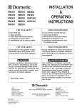
LIMITED TWO.YEAR WARRANTY DOMETIC REFRIGERATORS
THE SELLER NAMED BELOW MAKES THE FOLLOWING WARRAHTY
WITH RESPECT TO THE DOMETIC PRODUCT:
1.
This warranty is made only to the first purchaser (herein after referred to as the "Original Purchaser"'l wtlo a@urres the productfor his own
use and is installed and operated within the continental United States and Canada.
2.
This warranty will be in effect for two years on parts and freight and two years on labor from the date of ;xJr,dlas€ by the Original Purchaser.
It is suggested that the original purchaser retain a copy of the dated bill of sale as evidence of the cate rf purchase.
3.
This warranty covers only specified parts, which shall be free from defects in material and workmansF p ucrder normal use. This warranty
does not cover conditions unrelated to the material and workmanship of the product. Such unrelatd co,nditions include, but are not limited
to: (a) damage not reported within the first 7 days of ownership; (b) faulty installation or installatlcr.. u.,at Coes not comply with RVIA standards, and any damage resulting from such; (c) the need for normal maintenance and any damage resulbng ftom the failure to provide
such maintenance; (d) failure to follow Sellers instructions for use of product; (e) any accident to o{ Fiis'rse ct any part of this product and
any alteration by anyone other than the Seller or its authorized representative; (f) any non-Donretic pacs Slat are installed as replacement
parts will void any warranty (implied or written); (g) blow out conditions; (h) radio frequency interference and eleclromagnetic interference;
(i) 12V system chassis ground decay and corrosion; O puncture of foam cabinet or vacuum inzulated panels afier acknowledged receipt;
(k) animal or insect infiltration which damages unit or inhibits performance; (l) abuse or misuse of alertrcal cornponents.
4.
vave lurner. bumer housing, electronic
display, electronic module, evaporator fins, foam integrity, frame, thermistol spark probe, igniticn *ire. rce maker compressor, second
absorption loop, display escutcheon, lower toe plate, humidity switch, frame heater mullion, ice maker rnui{irn) are covered for parts and
freight for two years and labor for two years from date of purchase. All other components that fail rnust be reported within the first 90 days
of ownership in order to receive coverage of parts, freight and labor under warranty.
5.
This warranty requires the Origina! Purchaser to provide preventative maintenance on a yearty basb, starting at the anniversary
of his date of purchase. The Original Purchaser must keep a record of the preventative maintenarce to keep the warranty in effect.
Failure of the Original Purchaser in providing this annual maintenance may void the wananty. 'firc praneotative maintenance must be
performed at a Dometic Authorized Service Center/Dealer. The preventative maintenance requrred s an inspection, cleaning and full
diagnostics performed on the entire electronic system, burner assembly, wiring and cooling unit A copy of the receipt covering the maintenance checks must accompany the warranty claim during the second year of ownership. The cosr of trlrs preventative maintenance is
the Original Purchaser's responsibility and should take about one hour.
6.
ln order to obtain the benefits of this warranty, the original purchaser must return the product whicfr rs fotind defective to the Seller named
below or to a Dometic Authorized Service Center during the period that this warranty is in effeci. The onginal purchaser is responsible for
all charges incurred in delivery of the product to the Seller or Dometic Authorized Service Center, and rn 3{ck up after the warranty service
has been completed. To obtain the location of the nearestAuthorized Service Center, please call 1 80O 544-488'l or in Canada call 1-519653-4390.
7.
Any item returned in the manner described in paragraph 6 will be examined by the Seller or the Aulfiorued Dometic Service Center. lf it is
found that the returned item was defective in material and workmanship, the Seller or theAuthorized Dorretic Service Centerwill repair the
product per the terms outlined in paragraph 4. CONFIRM THE SERVICE AGENCY lS AN AUTHORIZED DOMETIC SERVICE CENTER.
DO NOT PAY THE SERVICE AGENCY FOR WARRANTY REPAIRS. SUCH PAYMENTS WILL NOT BE REIMBURSED.
8.
The Seller does not authorize any person or company to create any warranty obligations or liat*lity on f'pir behaif. This warranty is not
extended by the length of time which you are deprived of the use of the product. Repairs and replacernen't parts provided under the terms
of this warranty shall carry only the non-expired portion of this warranty.
ln no event shall either seller be liable for incidental or consequential damages. This includes any damage to another product or products
resulting from such a defect. Some states do not allow the exclusion or limitation of incidental or consequential damages, so the above
limitations may not apply.
9.
The specified parts covered by this warranty are as follows: Major components (cooling unit, LP gas
10. Any implied warranty, including the implied warranty of merchantability
and fitness for any purpose, is limited to the duratjon of this limited
warranty. Some states do not allow limitations on how long an implied warranty can last, so the above limitation may not apply.
11.
THIS WARRANTY GIVE SPECIFIC LEGAL RIGHTS, YOU MAYALSO HAVE OTHER RIGHTS WHICH VARY FROM STATE TO STATE.
No action to enforce this warranty shall be commenced later than ninety (90) days after the expiration of the warranty period. Claims must
be submitted in writing to the Dometic Warranty Department for arbitration.
12, All products(exceptthosespecificallybuiltforcommercial use)arewarrantedonlywheninstalledinvehidesbuitttocunenteditionR.V.l.A
A119.2 and C.R.V.A. 2-240 Standards.
13. The Seller reserves the
right to change the design of any product without notice and with no obligation to make conesponding changes
in products previously manufactured.
DOMET!C, LLG
Warranty Department
2320 Industrial Parkway
Elkhart, lN 46516
Phone: 574-294-2511
Fax: 574-389-3975
REFRIGERATOR OWNER MAINTETTAUCE YCAruV NECONO
Customer Name:
\Iodel No.:
Address:
Date of Purchase:
Seria] No.:
City:
State:
Phone:
Zip Code:
FIRSTYEAR
SECOND YEAR
Date:
Date:
-
Dealership:
Dealership:
Address:
-{ddress:
City:
Citl:
State:
Zip:
State
Zip:
Phone:
Iechnician:
Cleaned Bumer Assembly:
All Terminals Connections:
Cleaned/Inspect All Ground Connections:
Cleaned/Check
Yes
Inspect and Test Door Seals:
Inspect and Tighten Lp Lines:
Power Ventilator Installed:
*Gas Safefy Shutdown in 45
seconds:
ACTUAI,
Yes /
No
Yes /
No
Yes /
\o
Yes
Yes / No
Power Ventilator Installed:
*Gas Safety Shutdown
in 45 seconds:
yes / No
yes / No
yes / No
SPEC. RANGE
Thermister Reading
7-10,000 ohms @ 32'
9.5
to
15 voits
120 Volts
Thermocouple Reading
25-35 Millivolts
+
ACTUAL
DiC
+A"/C Voltage
andAll Connections:
Thermister Reading
7-10,000 otuns
*D C \bltage
9.5
C
\bltage
to
15 volts
@32'
D/C
l20Volts+ l0%
Thermocouple Reading
25-35 Millivolts
*Delav Benveen
Modes
Approx. 5 seconds
RV Diagnostic Tool for these tests.
ICEMAKER MODELS
Yes
/No
Yes
/No
Inspect Water Valve and A1l
Inspect Heat Tape Switch for proper
Operation:
3/16"
+ Use PAL
ICEMAKERMODELS
SPEC. RANGE
Elecrode Gap
*-{
10%
*Delay Between Modes
Approx. 5 seconds
* Use PAL RV Diagnostic Tool for these
tests.
Inspect Water Valve
Inspect and Test Door
yes / No
yes / No
Seals:
Inspect and Tighten Lp Lines:
Yes / No
3/t6"
yes / No
yes / No
Cleaned Check
i No
Electrode Gap
*D/C Voltage
Assembly:
All Terminals Connections:
Cleaned,/lnspect All Ground Connections:
Cleaned Burner
i No
Connections:
yes / No
Inspect Heat Tape Switch for proper
Operation:
27
Yes
/No