1
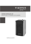
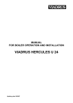
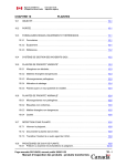
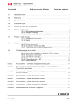
VIADRUS HERCULES U 24
Manual for boiler operation and installation
GB_2014_21
Table of contents
1.
2.
3.
page
Technical information ................................................................................................................................. 3
1.1
Usage .................................................................................................................................................. 3
1.2
Boiler advantages................................................................................................................................ 3
1.3
Boiler technical data ............................................................................................................................ 4
1.4
Basic boiler dimensions ...................................................................................................................... 6
1.4
Basic boiler dimensions ...................................................................................................................... 6
Assembly manual ....................................................................................................................................... 9
2.1
Boiler construction ............................................................................................................................... 9
2.2
Rules and directives ............................................................................................................................ 9
2.3
Positioning possibilities ....................................................................................................................... 9
2.4
Delivery and accessories .................................................................................................................. 12
2.5
Assembly technique .......................................................................................................................... 12
2.6
Boiler commissioning ........................................................................................................................ 17
2.6.1
Verification activities before commissioning .............................................................................. 17
2.6.2
Boiler commissioning ................................................................................................................. 17
2.7
Control and safety elements ............................................................................................................. 17
2.8
Equipment for surplus heat withdrawal ............................................................................................. 17
2.9
Equipment for heat withdrawal – accumulation tank......................................................................... 19
Manual for operation................................................................................................................................. 20
3.1
Boiler operation by user .................................................................................................................... 20
3.2
Boiler cleaning - maintenance ........................................................................................................... 22
3.3
IMPORTANT NOTICE ...................................................................................................................... 23
4.
Instruction for product disposal after its service life ................................................................................. 24
5.
Guarantee and the liability for defects ...................................................................................................... 25
Dear customer,
we thank you that you have bought VIADRUS HERCULES U 24 universal boiler, thus having shown
your confidence in VIADRUS a.s.
For you to get used to a correct way of handling your new product from the beginning please read at
first this manual for its usage (first of all the chapter no. 3.1 – Boiler operation by user and chapter
no. 3.3 – IMPORTANT NOTICE). Please follow the stated information whereby a longlife and troublefree boiler operation will be guaranteed for both your and our satisfaction.
1.
Technical information
VIADRUS HERCULES U 24 is cast-iron low-pressure boiler designed for combustion of solid fuels – light
coal, hard coal and coke. As a complement fuel it is possible to use wood.
Combustion of other materials, like plastics is impermissible.
1.1
Usage
Three-sectional size of VIADRUS HERCULES U 24 boiler is suitable for heat sources reconstruction in
independent tenements, for smaller residential premises and leisure amenities. Bigger sizes of boiler
(4 – 10 sections) meet the demands on heating of family houses, shops, schools, etc.
The boiler is manufactured as a hot-water boiler with both natural and forced heating water circulation and
working overpressure up to 400 kPa (4 bar). Before dispatch the boiler is tested for tightness by applying
800 kPa (8 bar) testing overpressure.
The boiler is designed for heating both closed and open heating systems.
1.2
Boiler advantages
1. Long lifetime of the cast-iron heat exchange and all other parts with regard to the quality of used
materials.
2. Long-term verified construction.
3. Sophisticated manufacturing technology on the automatic forming lines with a constant and verified
quality of the manufacturing process (ISO 9001, ISO 14 001).
4. Combustion efficiency 80 %.
5. Easy operation and maintenance.
6. Output graduation according to the sections number.
Pressure loss independence on pz – Q flow rate
Pressure loss Pz (Pa)
čl. = sections
Flow rate Q
Fig. no. 1
Hydraulic loss of boiler drum
3
1.3
Boiler technical data
Tab. no. 1 Dimensions, technical data
Number of sections
pc
Boiler class according to EN 303 - 5
Combustion chamber volume
l
Water space volume
l
Weight
kg
Combustion chamber depth
mm
Diameter of smoke socket
mm
Boiler dimensions: height x width
mm
depth L
mm
Filling opening dimensions
mm
Maximum working water overpressure
kPa
(bar)
Minimum working water overpressure
kPa
(bar)
Testing water overpressure
kPa
(bar)
Boiler hydraulic loss
Minimum output water temperature
°C
Control range of water temperature
°C
Noise level
dB
Boiler connections – heating water
“
– return water
“
Cooling water temperature for
°C
equipment for surplus heat withdaral
Cooling water overpressure for
kPa
equipment for surplus heat withdaral
(bar)
3
4
5
6
23,6
39,5
262
220
37,6
49,3
312
330
51,6
59,1
362
440
156
65,6
68,9
412
550
714
825
7
8
9
10
79,6
78,7
462
660
93,6
88,5
512
770
107,6
98
562
880
176
121,6
107,8
612
990
3
1161 x 665
1047 1158 1269 1380
245x 195
400
(4)
50
(0,5)
800
(8)
See Fig. no. 1
60
60 – 85
Does not exceed the level 65 dB (A)
6/4
6/4
936
1491
5 – 20
200 – 600
(2-6)
Tab. no. 2 Technical data – hard coal as fuel
granularity 20 – 40 mm, fuel moisture max. 15 %
-1
calorific value of fuel: 14 – 20 MJ.kg
Number of sections
Nominal heat output
Fuel consumption at nominal heat
output
Minimum heat output
Fuel consumption at minimum heat
output
Fuel efficiency
Burning time at nominal output
Flue gases temperature at nominal
heat output
Flue gases temperature at minimum
heat output
Flue gases mass flow rate at nominal
output
Flue gases mass flow rate at
minimum heat output
Efficiency
Required chimney draught
pc
kW
3
11
4
19
5
25
6
31
7
37
8
43
9
49
10
55
kg.h
2,60
3,80
5,00
6,20
7,40
8,60
9,80
11,00
kW
3,9
5,7
7,5
9,3
11,1
12,9
14,7
16,5
0,79
1,15
1,51
1,87
2,23
2,60
2,96
3,32
-1
-1
kg.h
-1
MJ.kg
hour
19,81
4
°C
220 – 250
°C
110 – 120
g.s
-1
10,65
15,57
20,49
25,41
30,33
35,24
40,16
45,08
g.s
-1
4,92
7,19
9,46
11,73
14,00
16,27
18,54
20,81
0,13
0,14
0,15
0,20
0,28
0,30
0,32
%
mbar
78
4
0,22
Tab. no. 3 Technical parameters – hard coal as fuel
granularity 20 – 40 mm, fuel moisture max. 15 %
-1
Calorific value of fuel: 26 - 29 MJ.kg
Number of sections
Nominal heat output
Fuel consumption at the nominal heat
output
Minimum heat output
Fuel consumption at minimum heat
output
Fuel efficiency
Burning time at nominal heat output
Flue gases temperature at nominal heat
output
Flue gases temperature at minimum
heat output
Flue gases mass flow rate at nominal
heat output
Flue gases mass flow rate at minimum
heat output
Efficiency
Required chimney draught
pc
kW
3
11
4
25
5
32
6
42
7
46
8
53
9
60
10
68
kg.h
2,71
3,76
4,82
5,87
6,92
7,98
9,03
10,08
kW
5,4
7,5
9,6
11,7
13,8
15,9
18
20,1
0,79
1,10
1,41
1,72
2,03
2,34
2,65
2,95
-1
-1
kg.h
-1
MJ.kg
hour
28,31
4
°C
250 – 270
°C
130 – 200
g.s
-1
14,11
19,6
25,08 30,57 36,06 41,54 47,03 52,52
g.s
-1
4,56
6,33
8,10
9,87
0,15
0,16
0,17
0,20
0,24
0,28
0,32
0,35
%
mbar
11,64 13,41 15,18 16,96
79
Tab. no. 4 Technical parameters – coke as fuel
granularity 20 – 40 mm, fuel moisture max. 15 %
-1
caloric value of fuel: 26 - 30 MJ.kg
Number of sections
Nominal heat output
Fuel consumption at the nominal
output
Minimum heat output
Fuel consumption at minimum heat
output
Fuel efficiency
Burning time at the nominal output
Flue gases temperature at nominal
heat output
Flue gases temperature at minimum
heat output
Flue gases mass flow rate at nominal
heat output
Flue gases mass flow rate at
minimum heat output
Efficiency
Required chimney draught
pc
kW
3
17
4
25
5
37
6
46
7
52
8
58
9
66
10
74
kg.h
2,27
3,55
5,39
6,52
7,38
8,23
9,36
10,50
kW
4,8
7,5
11,4
13,8
15,6
17,4
19,8
22,2
0,68
1,06
1,62
1,96
2,21
2,47
2,81
3,15
-1
-1
kg.h
-1
MJ.kg
hour
27,8
4
°C
200 – 280
°C
120 - 190
g.s
-1
12,78
19,97
30,35
36,74
41,53
46,32
52,71
59,10
g.s
-1
6,19
9,66
14,69
17,78
20,10
22,42
25,51
28,61
0,20
0,22
0,25
0,28
0,32
0,35
0,40
%
mbar
80
5
0,30
1.4
Basic boiler dimensions
L
L1
D
mm
mm
mm
3
714
480
4
825
591
Fig. no. 2
5
936
702
156
6
1047
813
7
1158
924
Basic boiler dimensions
6
8
1269
1035
9
1380
1146
176
10
1491
1257
1
2
3
4
5
6
7
8
9
10
11
12
Front cell
Center cell
Rear cell
Feeding gate (with the rosette of primary air)
Partition of combustion space
Cleaning cover
Dump grate
Ash gate (with the secondary air flap)
Smoke extension piece (tertiary air)
Air rosette (tertiary air)
Boiler case (complete)
Thermo-manometer
Fig. no. 3
13
14
15
16
17
18
19
20
21
Draught regulator
Pipe of input water
Filling and cock
Pipe of output water
Two-way safety cock
Safety valve
Small ash pan (tertiary air)
Ash pan
Partition of the smoke adapter
Basic boiler parts
7
Fig. no. 3a) The location of partitions of the combustion chamber
Fig. no. 4
Supplement of main boiler parts for sizes 8 – 10 cells
8
2.
Assembly manual
2.1
Boiler construction
The main boiler part is the cast-iron sectional boiler drum made of the grey cast-iron according to
EN 1561, quality 150.
The pressure parts meet the strenght demands according to EN 303-5 - Boilers for central heating – Part 5:
Solid fuel boilers for central heating with manual or automatic feed and max. 500 kW nominal thermal output:
terminology, requirements, testing and marking.
The boiler drum is assembled of sections by means of pressed boiler nipples with 56 mm diameter and
secured by anchor bolts. The boiler sections create the feed space, combustion and ash space, water space
and convectional space. The heating water input and output is situated at the rear boiler part.
There is placed the smoke adapter and heating water connection at the upper part of rear boiler section and
the return water connection at the bottom part. The water connection is possible to connect by means of
thread pipes. The stoking door, ash door and cleaning cover are connected to the front boiler section. Under
the ash pan door there is installed the tilting grate.
There are placed the combustion space barriers behind the clearing cover. The partitions are inserted into
the third flue from above of the boiler drum (see Fig. no. 3a). Their quantity differs for each size of boiler (see
Tab. no. 5).
The whole boiler drum is insulated by the health harmless mineral insulation, which reduces the losses
caused by heat transmission into the environment. The boiler sell is coloured by a good quality comaxit
spray.
Tab. no. 5 Quantity of combustion space barriers
Size of boiler
3 sec.
4 sec.
5 sec.
Single channel barier of
1
combustion space (pc)
Double channel barier of
1
1
combustion chamber (pc)
2.2
6 sec.
7 sec.
8 sec.
9 sec.
10 sec.
1
1
-
-
1
1
1
2
2
2
Rules and directives
The solid fuel boiler can be installed by the company holding a valid certification for its installation and
maintenance. There must be made lay-out according to the valid rules for the boiler installation. Before the
boiler installation to the older heating system the installation company must make the flush (cleaning) of the
whole heating system. The heating system must be filled with water meeting the requirements
ČSN 07 7401, especially its hardness must not exceed the required parameters.
Recommended values
hardness
mmol/l
2+
Ca
mmol/l
Concentration of whole Fe + Mn
mg/l
*) recommended value
1
0,3
(0,3)*
WARNING!!! The use of anti-freeze mixture is not recommended by the manufacturer.
In case of two way safety vent reaction, when there is a possibility of boiler having been filled with
the water, which does not meet the ČSN 077401 requirements it is necessary to change the water in
the heating system so that it meets the ČSN 077401 requirements again.
a) to the heating system
ČSN 06 0310
Heating systems in buildings – Designing and installation
ČSN 06 0830
Heating systems in buildings – protecting device
ČSN 07 7401
Water and steam for thermal energy equipments with working pressure
up to 8 MPa.
EN 303-5
Boilers for central heating – Part 5: Solid fuel boilers for central heating with
manual or automatic feed and max. 500 kW nominal thermal output: terminology,
requirements, testing and marking.
b) to the chimney
ČSN 73 4201
Chimneys and flue gas ducting– designing, implementation and connection of fuel
consumers.
c) regarding the fire regulations
ČSN 06 1008
Fire safety of heat installations.
EN 13501-1 +A1
Fire classification of construction products and building elements – Part 1:
Classification using test data from reaction to fire tests
9
d) to the system of HWS heating
ČSN 06 0320
Heating systems in buildings – Hot water preparation – Designing and planning
ČSN 06 0830
Heating systems in buildings – Safety devices.
ČSN 75 5409
Water installations inside buildings.
2.3
Positioning possibilities
Boiler positioning in the living space (including corridors) is prohibited!
A continuous air supply for burning and eventual ventilation must be ensured for the room where the
boiler is installed.
The installation of the boiler must comply with all requirements of ČSN 06 1008.
Boiler positioning with regard to the fire regulations:
1. The boiler can be installed on a fire-proof floor (Fig. no. 5):
−
Place the boiler on fire-proof base exceeding the boiler platform by 20 mm on sides and only up to
the boiler drum depth.
−
If the boiler is positioned in a cellar, we recommend to install it on a retaining wall minimum 50 mm
hight.
−
Install the boiler in the middle of the retaining wall.
Quantity of sections
L mm]
3
383
4
494
Fig. no. 5
5
605
6
716
7
827
8
938
9
1049
10
1160
Boiler base dimensions
2. A safe distance from the combustible materials:
−
when installing and operating the boiler it is necessary to keep a safety distance of 200 mm from the
materials of combustibility grade A1, A2, B and C (D);
−
for easily combustible materials of combustibility grade E (F), which quickly burn and burn
themselves even after removal of ignition source (such as paper, cardboard, asphalt and tar paper,
wood and wood-fiber boards, plastics, floor coverings) the safe distance has to be doubled, i.e. to
400 mm;
−
safe distance should be doubled as bulb where the grade of reaction to fire has not been proved.
10
Tab. no. 6 Grade of reaction to fire
Examples of building materials and products included in the reaction to fire
(Extract from EN 13 501-1 + A1)
A1 – incombustible
Granite, sandstone, concrete, bricks, ceramic tiles, mortars, fireproof plasters, …
A2 – combustible with difficulty acumin, izumin, heraklit, lignos, boards and basalt felt, fibreglass boards,...
B – hardly combustible
Beech and oak wood, hobrex boards, plywood, werzalit, umakart, sirkolit,...
C (D) – medium combustible
Pinewood, larch, whitewood, chipboard and cork boards, rubber flooring,...
Asphaltboard, fibreboards, cellulose materials, polyurethane, polystyrene,
E (F) – easily combustible
polyethylene, PVC,…
Grade of reaction to fire
Boiler positioning with regard to the necessary handling space:
•
•
•
•
Basic environment AA5/AB5 according to ČSN 33 2000-1 ed. 2.
In front of the boiler there must be left a minimum handling area of 1000 mm.
The minimum distance between the rear part of boiler and the wall 400 mm.
At least from one side part keep the access area to the back boiler part of minimum 400 mm.
Fuel positioning:
•
•
•
It is interdicted to store the fuel behind the boiler or next to the boiler within a distance smaller than
400 mm.
It is interdicted to store the fuel between two boilers in the boiler-room.
The producer recommends to keep the distance between the boiler and fuel min. 1000 mm or to store
the fuel in a different room that where the boiler is installed.
The selection of the right boiler size
The selection of the right boiler size, it means the heating output, is very important condition for economic
operation and the right boiler function. The boiler must be selected so that the heating output conforms to the
heating loss of the object. The nominal output of the boiler is counted according to the valid rules for outside
temperature –12 °C, -15 °C and –18 °C. The boiler selection with too high heating output (overrating) results
in tarring and ratting of boiler. It is not useful to use the boiler with higher output than the heating loss of the
boject.
Chimney draught
The chimney with the right chimney draught is the fundamental prerequisite for the right boiler function. It
influences the boiler output as well as its efficiency. The boiler can be connected to the venting unit with the
sufficient chimney draught, see. Chapter no. 1.3. and if the revision by the certified organization is made.
11
2.4
Delivery and accessories
Boiler is delivered according to the purchase order on the pallet, where the whole boiler drum is placed and
on the sides it is attached the wrapped boiler shell. The accessories are put inside the boiler drum,
accessible by opening the stoking door. The boiler is packed in a transport package and must not be tilted
over during the transport
Standard boiler delivery:
•
•
•
•
•
•
•
•
•
•
•
•
•
•
•
•
•
•
•
Boiler on the palette with due number of cells
Cover including ash pans and small ash pan in corresponding size
Thermo-manometer (1 pc)
Input and output cock Js 1/2“ (1 pc)
Draught regulator complete – for size 3 – 7 cells (1 pc), for size 8 - 10 cells (2 pcs)
Blind plug Js 6/4“ (1 pc)
Sealing under plug (1 pc)
Screw of stifling system (1 pc)
Magnetic element (1 pc)
Cover handle (1 pc)
Plastic ball (1 pc)
Connecting material for covers (see chapter 2.5)
Connecting material for pull rod of the smoke socket (see chapter 2.5)
Pipe of heating and recurrent water 6/4“ (2 pcs)
Cleaning tools (hook, brush with handle, tang, holder for cleaning tools)
Handling spanner (1 pc)
Box spanner with hex handle 902-13 (1 pc)
Manufacturing plate (1 pc)
Business and technical documentation
Necessary accessories: (is not included in delivery):
•
•
Two way safety valve DBV 1 – 02 (1 pc) incl. siesal (10 g); this equipment has not to be used in case of
open heating system
Safety valve – 1 pc
By request (is not included in delivery):
•
Filter 3/4“ – for delivery with the two way safety vent DBV 1 - 02
The necessary accessories and optional boiler accessories is not included in the boiler standard
price.
2.5
Assembly technique
Installation of the boiler body – two way safety valve DBV 1 -02
1. Fit the boiler drum on the retaining wall (substruction).
2. Mount to the boiler drum system outlet the connecting tube G 6/4“, connect the second end with heating
system.
3. Mount to the boiler drum system outlet the connecting tube G 6/4“, and connect the second end with the
heating system.
4. To connect two-way safety valve DBV 1 - 02 with connecting pipe of recurrent and heating water and with
the input of cold water and with the output of excessive heat according to Fig. no.10.
5. Mount the discharging valve to 1/2“ thread in connecting tube of heating water according to Fig. no. 3.
6. Set the smoke tube to the smoke adapter and insert it into the chimney. The diameter of smoke tube is
160 mm for sizes with 3 – 7 sections and pro sizes 8 – 10 sections it is 180 mm.
7. Screw the draught regulator into the opening in upper part of front section. The boiler draught regulator
adjustment procedure is described in the manual enclosed to the particular regulator. For version
with 8 – 10 sections there are used two draft controllers. Draft controller has to be screwed according to
Fig. no. 3 and 4).
8. Blind the threated opening JS 6/4“ in the front section with JS 6/4“ plug. Place the sealing under the plug.
12
Mounting of covers
1.
To take out the covers from the cardboard wrapping.
1
Left side cover part with insulation
(3 pcs of connecting spindles, 2 pcs of pivots)
Right side cover part with insulation
(3 pcs of connecting spindles, 2 pcs of pivots)
Upper cover part (4 pcs of spring clips)
2
3
Fig. no. 6
4
6
12
Left front upper cover part
Right front lower part (3 pcs of spring clips,
magnetic element, Nut M5)
Right front upper cover part
Location of connecting material in the boiler cover
13
2.
3.
1
2
3
4
5
6
To fit sheet components with due connecting material according to Fig. no. 6.
Connecting spindle
10 pcs
Washer 5, 3
Spring clip
10 pcs
Washer 8, 4
Screw ST 4, 2x9, 5
10 pcs
Screw M5x12
Pivot
6 pcs
Screw M8x12
Nut M10
2 pcs
Washer 10,5
Nut M5
1 pc
Magnetic element
According to the Fig. no. 7 – to cover the boiler.
Left side cover part with insulation
(3 pcs of connecting spindles, 2 pcs of pivots)
Right side cover part with insulation
(3 pcs of connecting spindles, 2 pcs of pivots)
Upper cover part (4 pcs spring clips)
Left front upper cover part
Left front cover part (3 pcs spring clips)
Right front lower part (3 pcs spring clips)
7
8
9
10
11
12
13
14
14
3 pcs
1 pc
7 pcs
1 pc
2 pcs
1 pc
Brace (4 pcs connecting spindles)
The brace console
Console of the cleaning covering
Pull rod of the smoke socket (complete)
Rear cover part
Right front cover part (2pcs pivots)
Magnetic element
Right front upper cover part
Fig. no. 7
The boiler sheathing
4.
5.
To equip the side part with connecting spindles and pivots.
To mount on the anchor bolts the side covers parts. To screw with use of nut M10 (2 pcs) and washer
10, 5 (2 pcs) in the upper part the console of the side cover part on the anchor bolts.
6. To mount on the brace the consoles of brace with use of screws M5x12 (detail F). To screw the brace to
the side cover parts with use of 1 pc of the connecting spindle (on the left) an 1 pc of the screw M 5x12
(on the right). To screw into remaining openings 3 pcs of connecting spindles with washers 5,3.
7. To mount the console of cleaning covering with use of screw M 8x12 and washer 8,4 (detail E).
8. To screw up the right front upper part and the left front upper part with use of 2 pcs of screws M 5x12
(detail A). To locate into the front upper cover part the thermo – manometer. To screw up the
manometer capillary into the check- valve and to locate the thermometer capillary into the pit and to
secure it with the capillary spring.
The parts prepared in such way ought to be located on the pivots of the side cover parts and the lower
part ought to be secure with nut M10 which is located on the screw of the upper stocking door lug
(detail C).
9. To equip the left front cover part with 3 pcs of spring clips. To shift the cover part under the nut M 10
which is located on the screw of the upper stocking door lug (detail D) and to fit it on the connecting
spindles of the side cover part.
10. To equip the right front lower cover part with 3 pcs of the spring clips and to fit them on the spindles
located on brace and on the side cover part.
11. Into the right front cover part :
- To insert magnetic element and to secure it using the nut M4 (detail B).
- To insert handle
- To screw up 2 pcs of pivots
To fit the cover part completed in such way with pivots into openings in the upper right cover part and to
clip them up.
12. The mounting of the pull rod of the smoke control according to the Fig. no. 8. Need of single parts:
- 2 pcs keeper pins
- 2 pcs washers 10,5
- 1 pc nut M 10
15
13.
14.
15.
16.
17.
To insert the keeper pin and to fit the washer 10,5 into the partition of the smoke extension piece. To
mount the pull rod on the partition of the smoke extension piece and to secure it with the washer 10,5
and the keeper pin - To screw up the nut M 10 on the pull rod.
To equip the upper cover part with 4 pcs of spring clips and to fit them on the side cover part.
To screw up the rear cover part with use of 10 pcs screws ST 4, 2x9, 5.
To screw up to the upper cover part the pull rod console with use of 2 pcs of screws M5x12. To locate
the pull rod of the smoke control into the oval opening into console and to secure with the plastic ball
M10.
To fit on the draught regulator the pull rod with chain let (in accordance with attached Manual of draught
regulator).
To locate ash pan and small ash pan according to the Fig. no. 3.
1
2
3
4
5
6
7
8
Fig. no. 8
Smoke extension piece
Partition of the smoke
extension piece
Pull rod of smoke control
Upper cover part
Keeper pin
Console of pull rod
Plastic ball M10
Rear cover part
Installation of the smoke control pull rod
Note: Before stoking it is necessary to open the partition in smoke adaptor by means of the draw
bar of smoke control. Thus the flue gases are discharged through the shorting opening into
the chimney.
Assembly tools for brush
Use the leather gloves and common assembly tools for mounting or dismounting of the brush and the spike
point (if they are included in the delivery).
Filling the heating system with water:
The water hardness must correspond to ČSN 07 7401 and it is inevitable to treat the water according
to Chap. no. 5.1. in case the water hardness is unsatisfactory.
The heating systems with an open expansion tank allow the direct contact between the heating water and
the atmosphere. During the heating season the water expanding in the tank absorbs the oxygen, which
increases its corrosive effects and at the same time the water evaporates heavily. Only the water treated to
the values according to ČSN 07 7401 can be used for refilling.
The heating system must be thoroughly flushed out in order to wash out all impurities.
During the heating season it is necessary to keep a constant volume of heating water in heating system and
be particular about bleeding the heating system to avoid the air suction into the system. Water from the
boilers and heating system must never be discharged or taken for usage except in cases of emergency like
the repairs etc. Water discharge and filling with new water increases the danger of corrosion and scale
development. In case we have to refill the heating system with water we only do this operation when
the boiler is cold in order to prevent its sections from getting broken.
After boiler and heating system refilling operation the all joints must be tested for tightness.
When using the two way safety vent DBV 1 - 02 the cooling water is added gradually to the to the
reverse water.
The assembly and stoking test completion must be recorded in the “Guarantee certificate”.
16
2.6
Boiler commissioning
This boiler can only be commissioned by a professional assembly firm authorized to do this activity.
2.6.1 Verification activities before commissioning
Before the boiler put into operation it is necessary to check:
a) filling the heating system with water (thermomanometer check) and the system tightness;
b) connection to the chimney – this connection can only be done with the agreement of a chimney
firm (chimney revision);
c) closing of smoke adapter partition (impurities associated with the installation of the boiler chimney
system);
d) draught regulator and thermostatic valve functionality.
2.6.2 Boiler commissioning
1. Fire a boiler
2. Bring the boiler to the necessary operating temperature. The recommended output water temperature is
80 C.
3. Adjust the draught regulator including the chain length (according to the enclosed draught regulator
manual).
4. Check the functionality of two-way safety valve DBV 1 - 02.
5. Operate the boiler in the operating condition according to the relevant standards.
6. Check again the boiler tightness.
7. Acquaint the user with the operation and maintenance.
8. Make a record in the Guarantee certificate.
2.7
Control and safety elements
Rosette of stoking door is used for primary air supply into the combustion chamber.
Stifling system in ash door regulates the supply of secondary combustion air under the grate of boiler.
It is controlled with the draught regulator or manually setting screw of the stifling system. The second draught
regulator (for size 8 – 10 cells) regulates the rear stifling system. The regulator is adjusted on the same
temperature as the regulator in the front boiler part.
The rose in the rear boiler part is used for the tertiary air inlet, which has to be slightly opened according to
the size of the boiler at 0 - 5 mm (at 3 and 4 boiler sections the air rosette is set on the rear boiler section to
0 - 1 mm and at 5 -10 boiler sections it is gradually increased as needed). In the front part of the boiler there
is a small ashtray for the supply of tertiary air supply. On the small ash pan there are stops for the gaps
between cell and ash pan assuring because of the air inlet. It is also possible, in case of necessity, to
enlarge this gap.
The combination appliance – thermo-manometer – is used for the heating water temperature and the water
stress in the heating system detection. The pit of the thermo-manometer sensor is located in the upper part
of the front boiler cell.
2.8
Equipment for surplus heat withdrawal
The two way safety vent DBV 1 - 02 serves for surplus heat removal in case the water temperature in
boiler exceeds 95 °C.
In case the system is equipped with a two way safety vent and the boiler becomes overheated (the output
temperature exceeds 95 °C) the two way safety vent creates a cold water circuit which is kept until the
temperature drops below the limit temperature. At this moment there are simultaneously closed the
discharge cooling equipment and the cold water inlet of refilling the system.
The two way safety vent DBV 1 – 02 technical data (from the firm Regulus)
Opening temperature (limit):
Maximum temperature:
Maximum stress on boiler side
Maximum stress on water side
Nominal flow at p 100 kPa (1 bar):
100 °C (+0° - 5 °C)
120 °C
400 kPa (4 bar)
600 kPa (6 bar)
3
1,9 m /h
17
Usage
The two way safety vent DBV 1 – 02 is used as a protection of heating boilers against overheating. In the
valve body there is the bleed and supply valve controlled by thermostatic element. When the limit
temperature is reached, the bleed and supply valve is simultaneously opened meaning that the cold water is
running in and the hot water is running out. When the temperature drops below limit, the bleed and supply
valve is simultaneously closed.
Caution! It is not a compensation for safety valve.
In case of two way safety vent reaction, when there is a possibility of boiler having been filled with
the water, which does not meet the ČSN 077401 requirements it is necessary to change the water in
the heating system so that it meets the ČSN 077401 requirements again.
A – cold water inlet
B – output to boiler
C – output to drain
D – input from boiler
Fig. no. 9
The two way safety vent DBV 1 - 02
1 – Boiler
7 – Pump
2 – Two way safety vent DBV 1 – 02
8 – Surplus heat removal
3 – Safety valve
9 – Bleed valve
4 – Transforming valve
I – Cooling water inlet
5 – Filter
II – Heating water outlet
6 – Ball-shaped cock
III – Return water inlet
Fig. no. 10 The recommended scheme of the two way safety vents DBV 1 – 02 connection
It is necessary to install a safety valve for maximum overpressure of 400 kPa (4 bar) on the system
and its dimension must correspond to the rated boiler output. The safety valve must be located
directly behind the boiler. Any stop valve must not be located between the safety valve and boiler. If
you have any questions, please contact our contractual assembly firm and service organizations.
Installation
Installation can be only carried out by a qualified person. For the correct operation of the thermostatic, two
ways safety vent it is necessary to comply with the conditions for its installation and keep the flow directions
marking on its body. The safety vent is always mounted in the output pipe of boiler or directly on the upper
part of boiler, where the hot water leaves boiler and is transported into heating system. When installing the
18
vent it is necessary to check, if the 3/4“ socket usage, which can be both in pipeline and on boiler, ensures
complete immersion of the thermostatic vent element after the vent installation. After the vent has been
installed in socket, connect the down pipe, in which the hot water from boiler will flow to drain, to „C“(see. fig.
no. 9). The cooling water inlet, which will cool the boiler after setting the vent in operation, is connected (see
fig. No. 10) to „A“ (see fig. no. 9). The filter for mechanical impurities must be installed in the cooling water
inlet. It is necessary to connect the pipeline to „B“ (see. fig. no. 9) and the pipeline is to be led into reverse
flow pipe of heating system near the boiler (see fig. no. 10).
Regular maintenance
Once a year it is necessary to turn the safety vent’s head to remove possible impurities formed in the vent.
Clean the cooling water inlet filter.
In case of using an open expansion tank it is not necessary to use a pressure protecting device
against overheating.
Every heat source in an open heat system must be connected with an open expansion tank positioned at the
highest point of the heat system. The expansion tanks must be rated in the way that they can contain the
changes in water volume resulting from heating and cooling.
The open expansion tanks must be equipped with non-closable bleeder and an overflow pipes. The overflow
pipe must be designed in the way that it safely drains off the maximum flow volume entering the system. This
can be achieved by rating the overflow pipes by one DN higher than that of the filling piping. The expansion
tanks and their connecting pipes must be designed and positioned in the way that freezing is reliably
inhibited.
1
2
3
4
5
6
7
8
Fig. no. 11
2.9
Heat source
Expansion tank
Safety piping
Expansion piping
Overflow piping
Filling piping
Water level limiter
Reverse piping
The examples of open expansion tanks connection
Equipment for heat withdrawal – accumulation tank
In case that the required volume of heating system exceeds 300 l, we recommend to install the accumulation
tank.
The calculation of the minimum volume of stack heat exchanger:
Vsp = 15Tb x QN (1-0,3 x (QH/Qmin))
where:
Vsp
accumulation tank volume in l
QH
thermal load of buildings in kW
QN
nominal heat output in kW
Qmin
the minimum heat output in kW
Tb
burning time in hours
The dimensions of accumulation tanks for central heating boilers that are operated with individual prescribed
fuels, must be set according to the output, which needs the biggest accumulation tank. This type of
accumulation tank isn´t necessary in case that the calculated volume doesn´t exceed 300 l.
19
3.
Manual for operation
3.1
Boiler operation by user
SOFT COAL
The most suitable fuel is sort coal with 20 – 40 mm granularity.
Burning time at nominal output is 4 hours.
HARD COAL
The most suitable fuel is hard coal of 20 – 40 mm granularity.
Burning time at nominal output is 4 hours.
COKE
The most suitable fuel is coke of 20 – 40 mm granularity
Burning time at the nominal output is 4 hours.
ADDITIONAL FUEL – WOOD
Using this fuel it is not reached the nominal output.
Z
O
I.
II.
III.
primary air
secondary air
tertiary air
O
Z
open
closed
I.
III.
II.
III.
Fig. no. 12
Firing
1.
Check the water volume in the heating system on thermomanometer.
2.
Open the closing fittings between the boiler and the heating system.
3.
Clean the grate and ash-pan.
4.
Check the closed position of the smoke adapter partition (between bearing surface there might pieces of
coal, ash, soot).
5.
Insert the kindling and wood trough the ash door on the cleaned grate all over its depth.
6.
Light the kindling through the ash door.
7.
Close the ash door and open fully the choke. For 8 – 10 sectional version open the rear choke too.
8.
Before stoking it is necessary to open the partition in smoke adaptor by means of the draw bar of smoke
control. Thus the flue gases are discharged through the shorting opening into the chimney.
9.
Put the basic fuel bed on the burning wood.
20
10. When the fuel starts burning well, stoke another fuel up to the lower edge of the stoking door. During
stoking the fuel, do not fill the short circuit hole. For proper function of the boiler it is necessary that the
partition of the smoke adapter closes tightly (see chap. 2.6.1 item c).
11. After closing the stoking door close the partition of smoke adapter by means of the draw bar of smoke
control. Thus the shorting opening is closed.
Note: In course of making fire the boiler dewing can occur – it is not considered as a defect.
Fig. no. 13 Scheme of flue gas passage through the boiler
Operation
1. After having achieved the heating water temperature regulate the combustion air inlet. The boiler output
is regulated by choke, which regulates the secondary air inlet under the grate either manually or by use
of the draught regulator. Adjust the regulator so that the ash door choke is nearly closed at the moment
of achieving the required heating water temperature.
2. According to heat need and burning intensity, it is necessary to stoke the fuel up to the lower edge of the
stoking door (hot layer suitable for further fuel stoking is min. 15 cm). Stoke in the way making sure that
the fuel layer is equally high along the whole depth of the boiler. During stoking, do not fill the fuel into
the short circuit hole.
ATTENTION! Prior opening of the stoking door it is necessary to open the smoke adapter
partition with use of the smoke control pull rod.
3. When using hard coal and brown coal as fuel the rosette of stoking door for primary air supply must be
ajar at 3-5 mm and when using wood as fuel it must be opened at maximum. When using coke as fuel to
rosette must be fully closed.
4. The rosette in the rear part of the boiler must be ajar at 1 mm up to at 0 - 5 mm (at 3 and 4 boiler
sections the air rosette is set on the rear boiler section to 0 - 1 mm and at 5 -10 boiler sections it is
gradually increased as needed). Between the front section and a small ash pan there also must be a gap
(guaranteed by the backstops at the ash pan) to ensure the supply of tertiary air (if necessary this gap
can be enlarged).
Important notice!
The dark smoke from the chimney signals not fully closed partition of the smoke adapter or a
lack of tertiary air. A large volume of tertiary air results in cooling of flue gases and thereby
reducing the efficiency of the boiler. Full closure of stoking door rosette in case of hard and
brown coal can also cause dark smoke from the chimney and boiler tarring.
5. At the transition to the night top-fed stove damped operation the grate must be cleaned and freshly
stoked fuel must flare. Close the choke of ash pan door. The rosette of stoking door is also kept ajar the
draught controller in this case can be unhung (the choke completely closed).
6. The morning re-putting into operation make by opening the ash door choke, together with poking up the
grate after the ash door opening.
7. The ash door must be closed during the boiler operation.
8. If necessary, clean the ash pan (the gloves needed).
21
3.2
Boiler cleaning - maintenance
1. Ash from ash pan and small ash pan has to be removed in the boiler operation even several times a day
according to the type of used fuel, because full ash pan protects the correct division of the combustion
air under fuel and evokes rough burning of fuel on grate. Al residues in the boiler furnace, mainly cinder
have to be removed before each new burning start and in course of the morning boiler operation
reinsertion. It is necessary to put away the ash into the fireproof containers with covering. During working
period it is necessary to use safety helps and to care the personal safety.
2. In the course of the heating with coke, hard and brown coal it is necessary to clean regularly once a
month the boiler walls inside the feeding hopper and also the smoke extension part (Fig. no.14).
3. After the heating season end or as needed (this is influenced by the quality of fuel, chimney draught and
setting of boiler) it is necessary to clean up the boiler flue gas passage. It is necessary to screw off the
cleaning covering with use of socket spanner with handle, with use of assembly spanner, to put out the
partitions of the combustion space, to clean up the flue gas passages with pertinent cleaning tools. (Fig.
no. 15). After cleaning up it is necessary to put back the partitions of the combustion space in such way
in order the rear boiler part remained close and then to screw up the cleaning covering. Pull out the small
ash pan (at 5-10 boiler sections also the rear air-rosette) and clean up the air ducts by inserting your
hand with a wrench (see Fig. no. 15 - item 4) into the inlet of tertiary air.
4. Provided settlement of tar agglomeration on the combustion space walls has been occurred in course of
using fuels with greater gas formation we remove them with scraper or with burning out using hardwood
(eventually coke) under the boiler putting into maximum working temperature at the open partition of the
smoke adapter.
5. After the heating season ending it is necessary to clean the interconnection between the boiler smoke
adapter and chimney and then to treat pivots of the flue gas flap with the carbon grease.
1 – Screw with the hexagon head M5 x 14
2 – Washer 5,3
Fig. no. 14
3 – Cleaning covering of the smoke extension piece
4 – Insulation of the cleaning covering of the smoke
extension part
Cleaning of the smoke extension piece
22
1
2
3
4
5
6
Fig. no. 15
3.3
Front left cover part
Nut M8
Washer 8, 4
Assembly spanner
Cleaning covering
Hexagon socket spanner with handle
Dismantling of the cleaning covering
IMPORTANT NOTICE
1.
The boiler only can be used for the purpose that it is destined for.
2.
The boiler can be operated only by adult persons acquainted with this operation manual. It is
inadmissible to leave the children unattended by adults near the boiler. The boiler construction
intervention, which can endanger the attendant´s safety, eventually the housemate´s safety, is
inadmissible.
3.
The boiler is not destined for the use by persons (incl. children) whose physical, sensual or
mental disability or lack of experience and knowledge prevent them from a safe use of the
appliance unless they are supervised or if they were not instructed on the use of appliance by a
person responsible for their safety.
4.
Children should be supervised in order to ensure that they do not play with the appliance.
5.
If there occurs a danger or flammable vapours and gases development and penetration into the
boiler room, or at works accompanied by the temporary development of the fire or explosion
(gluing the floor covering, painting with combustible painting colours), the boiler must be duly
closed down before the works start.
6.
It is FORBIDDEN to use the flammable liquids for boiler firing.
7.
It is FORBIDDEN to overheat the boiler during its operation. Fill the boiler under the lower edge
of stoking door. Open the stoking door by use of plastic handle and half-open the ash door to
smoke vent the smoke gases.
8.
It is forbidden to put the flammable materials on the boiler or in its near distance.
9.
When cleaning the ashes at boiler there must not be put any flammable materials within
minimally 1500 mm distance from the boiler.
10. When operating the boiler at the temperature lower than 60 C the boiler drum can be bedewed,
which means the low-temperature corrosion and reduction of boiler drum service life. Therefore
23
we recommend to operate the boiler at the temperature of 60 C and higher. Possible corrosion
marks on boiler drum don´t mean a defect and they don´t affect the boiler function.
11. After the heating season termination it is necessary to clean the boiler, smoke-flues and smoke
adapter properly. Spread the graphitic grease on swivel taps, smoke flap mechanism and on
other flexible parts of boiler. Keep the boiler room clean and dry.
12. In case the heating system is not daily used in winter season, then the water from boiler must be
drained.
13. It is necessary to install a safety valve for maximum overpressure of 400 kPa (4 bar) on the
system and its dimension must correspond to the rated boiler output. The safety valve must be
located directly behind the boiler. Any stop valve must not be located between the safety valve
and boiler. If you have any questions, please contact our contractual assembly firm and service
organizations.
14. In case of two way safety vent reaction, when there is a possibility of boiler having been filled
with the water, which does not meet the ČSN 077401 requirements it is necessary to change the
water in the heating system so that it meets the ČSN 077401 requirements again.
15. During assembly, installation and operation of the appliance it is necessary to comply with
standards that apply in the relevant country of destination.
If you fail to meet these conditions you cannot requisite the guarantee repairs.
4.
Instruction for product disposal after its service life
VIADRUS a.s. is a contracting partner of the firm EKO–KOM a.s. with the client number F00120649.
The packages comply with EN 13427.
We recommend to dispose the packages in the following way:
plastic foil, cardboard cover, use a salvage point
metal strapping tape, use a salvage point
wooden base, is designated for a single usage and no longer can be used as a product. Its disposal is
subject to Act. 477/ 2001 Sb. a 185/2001 Coll.as amended.
Whereas the boiler is constructed from common materials, we recommend to dispose the individual parts as
follows:
the heat exchanger (grey cast-iron), use a junk
distribution pipes, shells, use a junk.
other metal parts, use a junk
insulation material ROTAFLEX, through a firm engaged in waste collection and disposal.
In case that the product has lost its serviceability, you can use the back collection service (if this is
introduced). If the originator has declared that it is the waste and it will be handled according to the
legislative provisions valid in the particular country.
24
5.
Guarantee and the liability for defects
VIADRUS a.s. provides the guarantee:
– For boilers 24 months after the boiler putting into operation, but maximum 30 months after the date it
was dispatched from the VIADRUS a.s.;
– For boiler drum 5 years after the date its dispatch from the VIADRUS a.s.
In case of possible complaint of boiler shell, the customer is obliged to sumit the packing label of the
boiler shell. It is placed on the cardboard, in which the shell has been dispatched.
The user is obliged to entrust the commissioning to the professional assembly firm and a fault
rectification to a contractual service accredited by the VIADRUS a. s., otherwise the guarantee for a
boiler proper function does not apply. “VIADRUS HERCULES U 24 boiler quality and completeness
certificate” serves after its filling as a “Guarantee certificate
A regular boiler maintenance must be done by its user.
Every notification of fault must be conveyed immediately after its detection, always in writing or via
the telephonic advice.
If the above instructions are not observed, the guarantee provided by the manufacturer will not be
recognized.
The manufacturer reserves the right to make modifications within the product innovations, that
needn´t be included in this manual.
The guarantee doesn´t apply to:
- the faults caused by a wrong assembly (see chapter 2.5) or wrong product operation (see chapter
3.1) and faults cause y wrong maintenance (see chapter 3.2);
- product damage arisen during the transport or other mechanical damage;
- faults cause by rought storage;
- faults and damage caused by failure to observe water quality in heating system see chap. no. 2.2
and 2.5 or by using the anti-freeze mixture;
- faults caused by the failure to observe the instructions stated in this manual;
- the faults caused by natural disasters or force majeure.
25
Information for customer
Packaging identification
Assessment reference
PE Plastic sacks, folie, corrugated board, iron and plastic fix
line
Identification of principal materials used. Paper, Polyethylene, iron, wood
Part 1: Summary of assessment
Standard/Report
Assessment requirement
1.1 Prevention by source
reduction
1.2 Heavy metals and
ensure below maximum permitted levels
for components
(CR 13695-1)
1.3 Other
ensure in compliance with
noxious/hazardous
(ČSN 77 0150-2, EN 13428)
substances
2 Reuse
ensure reusability in all terms of the
standard for the functional packaging unit
(EN 13429)
3.1 Recovery by material ensure recyclability in all terms of the
recycling
standard for the functional packaging unit
(EN 13430)
3.2 Recovery in the form
ensure that calorific gain is achievable for
of energy
the functional packaging unit
(EN 13431)
3.3 Recovery by
ensure compost ability in all terms of the
composting
standard for the functional packaging unit
(EN 13432)
Claim
Note
YES
YES
YES
NO
YES
YES
Iron - NO
NO
NOTE Conformity with EN 13427 requires affirmative responses to sections 1.1; 1.2; 1.3 and to at
least one of 3.1; 3.2; 3.3. In addition, where a claim of reuse is made section 2 should also
record affirmative responses.
Part 2: Statement of conformity
In the light of the assessment results recorded in part I above, this packaging is claimed to comply
with the requirements of EN 13427.
26
Annex to the guarantee certificate for customer- the user
Record of accomplished guarantee and post-guarantee repairs and regular product checks
Record
date
Contracting service
organization
(stamp, signature)
Carried out activity
27
Customer´s
signature
VIADRUS HERCULES U 24
VIADRUS a.s.
Bezručova 300 | 735 81 Bohumín
telefon: 596 083 050 | fax: 596 082 822
mail: [email protected] | www.viadrus.cz