1
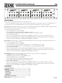
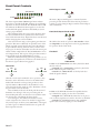
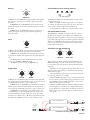
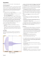
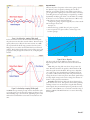
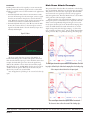
ms
250
dB
0
80
ACTIVE BYPASS
DEPTH
20
60
n:1
INT
8
6
ms
500
Hz
315
5k
1.25k
NORMAL LISTEN
LOW-CUT
20
80
1
20k
6.3k
3
2
MASTER
GATE DUCK EXP
HIGH-CUT
Hz
2k
Sec
.5
HOLD
200
630
0
.25
12 OL
2 Sec
6
RELEASE
25
125
3
250
OPEN
1
SIDE-CHAIN
EXT
RATIO
1
2
4
0
100
40
20
25
ATTACK
dBu
10
THRESHOLD
-60
-50
50
-1 TH
SIDE-CHAIN dBr
-3
LINK
2
dBu
20
10
dB
40
0
20
ACTIVE BYPASS
DEPTH
80
60
THRESHOLD
-60
-50
ms
50
250
100
n:1
4
INT
8
6
2 Sec
Hz
315
5k
1.25k
NORMAL LISTEN
20k
6.3k
3
2
GATE DUCK EXP
HIGH-CUT
Hz
2k
Sec
.5
HOLD
200
630
0
.25
12 OL
500
LOW-CUT
20
80
SIDE-CHAIN
EXT
RATIO
1
2
ms
6
RELEASE
25
3
250
OPEN
1
125
-1 TH
SIDE-CHAIN dBr
-3
ATTACK
0
25
-24 -12 -6
-30 -20 -10
-40
0
CLOSED
SLAVE
dBu
20
10
dB
40
0
20
ACTIVE BYPASS
DEPTH
80
60
THRESHOLD
-60
-50
-30 -20 -10
-40
0
CLOSED
ms
50
250
100
n:1
4
INT
8
6
2 Sec
Hz
315
5k
1.25k
NORMAL LISTEN
3
20k
6.3k
3
2
MASTER
GATE DUCK EXP
HIGH-CUT
Hz
2k
Sec
.5
HOLD
200
630
0
.25
12 OL
500
LOW-CUT
20
80
SIDE-CHAIN
EXT
RATIO
1
2
ms
6
RELEASE
25
3
250
OPEN
1
125
-1 TH
SIDE-CHAIN dBr
-3
ATTACK
0
25
-24 -12 -6
LINK
4
dBu
20
10
dB
40
0
20
ACTIVE BYPASS
DEPTH
80
60
THRESHOLD
-60
-50
ms
50
250
100
n:1
4
INT
8
6
3
ms
250
500
Hz
315
5k
1.25k
NORMAL LISTEN
LOW-CUT
20
80
20k
6.3k
3
2
GATE DUCK EXP
HIGH-CUT
Hz
2k
Sec
.5
HOLD
200
630
0
.25
12 OL
2 Sec
6
RELEASE
25
SIDE-CHAIN
EXT
RATIO
1
2
1
OPEN
125
-1 TH
SIDE-CHAIN dBr
-3
ATTACK
0
25
-24 -12 -6
-30 -20 -10
-40
0
CLOSED
SLAVE
POWER
G4
QUAD GATE
GATE
-30 -20 -10
-40
0
CLOSED
-24 -12 -6
G4
IMPORTANT SAFETY INSTRUCTIONS
1. Read these instructions.
2. Keep these instructions.
3. Heed all warnings.
4. Follow all instructions.
5. Do not use this apparatus near water.
6. Clean only with a dry cloth.
7. Do not block any ventilation openings. Install in accordance with manufacturer’s instructions.
8. Do not install near any heat sources such as radiators, registers, stoves, or other apparatus (including amplifiers) that produce heat.
9. Do not defeat the safety purpose of the polarized or grounding-type plug. A polarized plug has two blades with one wider than the other. A
grounding-type plug has two blades and a third grounding prong. The wide blade or third prong is provided for your safety. If the provided plug
does not fit into your outlet, consult an electrician for replacement of the obsolete outlet.
10. Protect the power cord and plug from being walked on or pinched particularly at plugs, convenience receptacles, and the point where it exits from
the apparatus.
11. Only use attachments and accessories specified by Rane.
12. Use only with the cart, stand, tripod, bracket, or table specified by the manufacturer, or sold with the apparatus. When a cart is used, use caution
when moving the cart/apparatus combination to avoid injury from tip-over.
13. Unplug this apparatus during lightning storms or when unused for long periods of time.
14. Refer all servicing to qualified service personnel. Servicing is required when the apparatus has been damaged in any way, such as power supply
cord or plug is damaged, liquid has been spilled or objects have fallen into the apparatus, the apparatus has been exposed to rain or moisture, does
not operate normally, or has been dropped.
15. The plug on the power cord is the AC mains disconnect device and must remain readily operable. To completely disconnect this apparatus from
the AC mains, disconnect the power supply cord plug from the AC receptacle.
16. This apparatus shall be connected to a mains socket outlet with a protective earthing connection.
17. When permanently connected, an all-pole mains switch with a contact separation of at least 3 mm in each pole shall be incorporated in the
electrical installation of the building.
18. If rackmounting, provide adequate ventilation. Equipment may be located above or below this apparatus, but some equipment (like large power
amplifiers) may cause an unacceptable amount of hum or may generate too much heat and degrade the performance of this apparatus.
19. This apparatus may be installed in an industry standard equipment rack. Use screws through all mounting holes to provide the best support.
WARNING: To reduce the risk of fire or electric shock, do not expose this apparatus to rain or moisture. Apparatus shall not be exposed to dripping
or splashing and no objects filled with liquids, such as vases, shall be placed on the apparatus.
WARNING
The symbols shown below are internationally accepted symbols
that warn of potential hazards with electrical products.
CAUTION
RISK OF ELECTRIC SHOCK
DO NOT OPEN
ATTENTION: RISQUE DE CHOCS ELECTRIQUE - NE PAS OUVRIR
To reduce the risk of electrical shock, do not open the unit. No user
serviceable parts inside. Refer servicing to qualified service personnel.
This symbol indicates that a dangerous voltage
constituting a risk of electric shock is present
within this unit.
This symbol indicates that there are important
operating and maintenance instructions in the
literature accompanying this unit.
WARNING: This product may contain chemicals known to the State of California to cause cancer, or birth defects or other reproductive harm.
NOTE: This equipment has been tested and found to comply with the limits for a Class B digital device, pursuant to part 15 of the FCC Rules.
These limits are designed to provide reasonable protection against harmful interference in a residential installation. This equipment generates, uses
and can radiate radio frequency energy and, if not installed and used in accordance with the instructions, may cause harmful interference to radio
communications. However, there is no guarantee that interference will not occur in a particular installation. If this equipment does cause harmful
interference to radio or television reception, which can be determined by turning the equipment off and on, the user is encouraged to try to correct
the interference by one or more of the following measures:
• Reorient or relocate the receiving antenna.
• Increase the separation between the equipment and receiver.
• Connect the equipment into an outlet on a circuit different from that to which the receiver is connected.
• Consult the dealer or an experienced radio/TV technician for help.
CAUTION: Changes or modifications not expressly approved by Rane Corporation could void the user's authority to operate the equipment.
This Class B digital apparatus complies with Canadian ICES-003.
Cet appareil numérique de la classe B est conforme à la norme NMB-003 du Canada.
INSTRUCTIONS DE SÉCURITÉ
1. Lisez ces instructions.
2. Gardez précieusement ces instructions.
3. Respectez les avertissements.
4. Suivez toutes les instructions.
5. Ne pas utiliser près d’une source d’eau.
6. Ne nettoyer qu’avec un chiffon doux.
7. N’obstruer aucune évacuation d’air. Effectuez l’installation en suivant les instructions du fabricant.
8. Ne pas disposer près d’une source de chaleur, c-à-d tout appareil produisant de la chaleur sans exception.
9. Ne pas modifier le cordon d’alimentation. Un cordon polarisé possède 2 lames, l’une plus large que l’autre. Un cordon avec tresse de masse possède
2 lames plus une 3è pour la terre. La lame large ou la tresse de masse assurent votre sécurité. Si le cordon fourni ne correspond pas à votre prise,
contactez votre électricien.
10. Faites en sorte que le cordon ne soit pas piétiné, ni au niveau du fil, ni au niveau de ses broches, ni au niveau des connecteurs de vos appareils.
11. N’utilisez que des accessoires recommandés par Rane.
12. N’utilisez que les éléments de transport, stands, pieds ou tables spécifiés par le fabricant ou vendu avec l’appareil. Quand vous utlisez une valise de
transport, prenez soin de vous déplacer avec cet équipement avec prudence afin d’éviter tout risque de blessure.
13. Débranchez cet appareil pendant un orage ou si vous ne l’utilisez pas pendant un certain temps.
14. Adressez-vous à du personnel qualifié pour tout service après vente. Celui-ci est nécessaire dans n’importe quel cas où l’appareil est abimé : si le
cordon ou les fiches sont endommagés, si du liquide a été renversé ou si des objets sont tombés sur l’appareil, si celui-ci a été exposé à la pluie ou
l’humidité, s’il ne fonctionne pas correctement ou est tombé.
15. La fiche du cordon d’alimentation sert à brancher le courant alternatif AC et doit absolument rester accessible. Pour déconnecter totalement
l’appareil du secteur, débranchez le câble d’alimentation de la prise secteur.
16. Cet appareil doit être branché à une prise terre avec protection.
17. Quand il est branché de manière permanente, un disjoncteur tripolaire normalisé doit être incorporé dans l’installation électrique de l’immeuble.
18. En cas de montage en rack, laissez un espace suffisant pour la ventilation. Vous pouvez disposer d’autres appareils au-dessus ou en-dessous de celuici, mais certains (tels que de gros amplificateurs) peuvent provoquer un buzz ou générer trop de chaleur au risque d’endommager votre appareil et
dégrader ses performances.
19. Cet appareil peut-être installé dans une baie standard ou un chassis normalisé pour un montage en rack. Visser chaque trou de chaque oreille de
rack pour une meilleure fixation et sécurité.
ATTENTION: afin d’éviter tout risque de feu ou de choc électrique, gardez cet appareil éloigné de toute source d’humidité et d’éclaboussures quelles
qu’elles soient. L’appareil doit également être éloigné de tout objet possédant du liquide (boisson en bouteilles, vases,…).
ATTENTION
CAUTION
RISK OF ELECTRIC SHOCK
DO NOT OPEN
ATTENTION: RISQUE DE CHOCS ELECTRIQUE - NE PAS OUVRIR
Afin d’éviter tout risque de choc électrique, ne pas ouvrir l’appareil.
Aucune pièce ne peut être changée par l’utilisateur. Contactez un
SAV qualifié pour toute intervention.
Les symboles ci-dessous sont reconnus internationalement
comme prévenant tout risque électrique.
Ce symbole indique que cette unité utilise un
voltage élevé constituant un risque de choc
électrique.
Ce symbole indique la présence d’instructions
d’utilisation et de maintenance importantes dans le
document fourni.
REMARQUE: Cet équipement a été testé et approuvé conforme aux limites pour un appareil numérique de classe B, conformément au chapitre 15
des règles de la FCC. Ces limites sont établis pour fournir une protection raisonnable contre tout risque d’interférences et peuvent provoquer une
énergie de radiofréquence s'il n'est pas installé et utilisé conformément aux instructions, peut également provoquer des interférences aux niveaux
des équipements de communication. Cependant, il n'existe aucune garantie que de telles interférences ne se produiront pas dans une installation
particulière. Si cet équipement provoque des interférences en réception radio ou télévision, ceci peut être detecté en mettant l'équipement sous/hors
tension, l'utilisateur est encouragé à essayer de corriger cette interférence par une ou plusieurs des mesures suivantes:
• Réorienter ou déplacer l'antenne de réception.
• Augmenter la distance entre l'équipement et le récepteur.
• Connecter l'équipement à une sortie sur un circuit différent de celui sur lequel le récepteur est branché.
• Consulter un revendeur ou un technicien radio / TV expérimenté.
ATTENTION: Les changements ou modifications non expressément approuvés par Rane Corporation peuvent annuler l'autorité de l'utilisateur à
manipuler cet équipement et rendre ainsi nulles toutes les conditions de garantie.
Cet appareil numérique de classe B est conforme à la norme Canadienne ICES-003.
Cet appareil numérique de classe B est conforme à la norme Canadienne NMB-003.
OPERATORS MANUAL
G4
QUAD GATE / DUCKER / EXPANDER
1
SIDE-CHAIN dBr
-24 -12 -6
-3
-1 TH
CLOSED
1
3
6
MASTER
12 OL
OPEN
-30 -20 -10
-40
0
-50
50
20
dBu
THRESHOLD
2
SIDE-CHAIN dBr
SLAVE
-24 -12 -6
.5
250
25
100
125
500
.25
0
250
25
2 Sec
0
2
ATTACK
40
3
Sec
ms
RELEASE
HOLD
315
2k
4
1
-30 -20 -10
-40
0
50
12 OL
6
-24 -12 -6
20
dBu
.5
250
25
100
125
500
.25
0
250
25
2 Sec
0
THRESHOLD
ATTACK
40
2
3
Sec
ms
RELEASE
4
-1 TH
HOLD
315
1
3
6
MASTER
12 OL
OPEN
-30 -20 -10
-40
0
-50
ms
-3
CLOSED
10
-60
3
SIDE-CHAIN dBr
3
OPEN
-50
ms
-1 TH
-3
CLOSED
10
-60
LINK
50
20
dBu
THRESHOLD
2k
4
SIDE-CHAIN dBr
SLAVE
-24 -12 -6
.5
250
25
100
125
500
.25
0
250
25
2 Sec
0
2
ATTACK
40
3
Sec
ms
RELEASE
4
-1 TH
HOLD
315
1
3
6
12 OL
OPEN
-30 -20 -10
-40
0
-50
ms
-3
CLOSED
10
-60
LINK
50
.5
250
25
100
125
500
.25
0
250
25
2 Sec
0
2
10
-60
20
dBu
THRESHOLD
2k
ms
ATTACK
40
RELEASE
4
HOLD
315
2k
60
20
2
6
80
1.25k 630
6.3k
60
20
2
6
80
1.25k
630
6.3k
60
20
2
6
80
1.25k
630
6.3k
60
20
2
6
80
1.25k
630
80
0
1
8
20
5k
20k
80
0
1
8
20
5k
200
20k
80
0
1
8
20
5k
200
20k
80
0
1
8
20
5k
200
dB
DEPTH
ACTIVE BYPASS
n:1
RATIO
INT
EXT
Hz
200
Hz
dB
LOW-CUT
HIGH-CUT
DEPTH
NORMAL LISTEN
GATE DUCK EXP
ACTIVE BYPASS
SIDE-CHAIN
n:1
RATIO
INT
EXT
Hz
Hz
dB
LOW-CUT
HIGH-CUT
DEPTH
NORMAL LISTEN
GATE DUCK EXP
ACTIVE BYPASS
SIDE-CHAIN
n:1
RATIO
INT
EXT
Hz
Hz
dB
LOW-CUT
HIGH-CUT
DEPTH
NORMAL LISTEN
GATE DUCK EXP
ACTIVE BYPASS
SIDE-CHAIN
n:1
RATIO
INT
EXT
G4
QUAD GATE
3
Sec
ms
Hz
6.3k
20k
Hz
LOW-CUT
HIGH-CUT
NORMAL LISTEN
GATE DUCK EXP
POWER
SIDE-CHAIN
Quick Start
If you read just one page of a manual this year, it should be this one.
If you are not familiar with the operation of Gates, Duckers and Expanders, see the Operation section on page Manual-4 for a
good tutorial. For those of you familiar with their operation, this quick start should help you get up and going fast.
Basic Gating: The G4 allows complete Gate envelope control: Threshold, Attack, Release and Hold. Side-chain metering accurately
and consistently indicates where the key signal is relative to the Threshold (dBr).
A good starting procedure is as follows:
1. Select the GATE mode and set for BYPASS.
2. Select side-chain key source for INTernal or EXTernal as required.
3. Set ATTACK to 0 ms, RELEASE for 250 ms, HOLD for 125 ms and DEPTH for 20 dB.
4. Select side-chain LISTEN.
5. Listen to the key signal and adjust the LOW-CUT and HIGH-CUT filters to respond only to frequencies of interest.
6. Watch the SIDE-CHAIN meter and adjust the THRESHOLD until the yellow TH indicator lights at the desired level.
7. Set the side-chain from LISTEN to NORMAL and the BYPASS to ACTIVE.
Basic ducking: As with the gate, the G4 provides complete Ducking envelope control. Figure 5 on page Manual-6 graphs the response. A good starting procedure is as follows:
1. Select the DUCK mode and set for BYPASS
2. Select side-chain key source for EXTernal. Ducking always uses an external side-chain key input.
3. Set ATTACK to 0 ms, RELEASE for 1 second, HOLD for 3 seconds and DEPTH for 20 dB.
4. Select side-chain LISTEN.
5. Listen to the key signal and adjust the LOW-CUT and HIGH-CUT filters to respond only to frequencies of interest.
6. Watch the SIDE-CHAIN meter and adjust the THRESHOLD until the yellow TH indicator lights at the desired level.
7. Set the side-chain from LISTEN to NORMAL and the BYPASS to ACTIVE.
Basic Expander: Expander operation is similar to that of the Gate, with two important control differences:
• The HOLD control is not active in EXPand mode.
• The RATIO control is used in place of the DEPTH control.
1. Select the EXPand mode and set for BYPASS.
2. Select side-chain key source for INTernal or EXTernal as required.
3. Set ATTACK to 100 ms, RELEASE for 500 ms, RATIO for 3:1.
4. Select side-chain LISTEN.
5. Listen to the key signal and adjust the LOW-CUT and HIGH-CUT filters to respond only to frequencies of interest.
6. Watch the SIDE-CHAIN meter and adjust the THRESHOLD until the yellow TH indicator lights at the desired level.
7. Set the side-chain from LISTEN to NORMAL and the BYPASS to ACTIVE.
Contents
Front Panel Controls............................................................2
Operation.............................................................................4
Side-chain Detector..........................................................4
Gate Mode.........................................................................4
Expand Mode.....................................................................5
Duck Mode.........................................................................6
Kick Drum Attack Example.................................................6
WEAR PARTS: This product contains no wear parts.
Manual-1
Front Panel Controls
Meters
Active / Bypass switch
SIDE-CHAIN dBr
ACTIVE BYPASS
-24 -12 -6
CLOSED
-3
-1 TH
1
3
6
12 OL
OPEN
The eleven-segment SIDE-CHAIN signal meter indicates
level relative to the Threshold (dBr), allowing easy and intuitive
adjustment of the Gate threshold. The Threshold indicator TH
is lit whenever the filtered side-chain signal is at or above the
set threshold. The signal peak value is held briefly to assist in
setting a proper threshold.
Meter ballistics follow the response of the side-chain detector. Gate and Duck modes use peak detection with instantaneous attack and 25 ms decay. Expand mode uses rms detection
with an averaging time constant of 50 ms.
Gate status is shown using a seven-segment gain reduction/
gate meter. This meter is effectively an expanded version of the
simple “stop light” meter found on many gates. The inclusion
of gain reduction metering allows the user to view the transition progress of the Gate and Ducker as well as the current gain
reduction when in Expand mode. The CLOSED LED is not active in Expand mode. The response of the gain reduction meter
accurately follows the Attack/Hold/Release envelope.
With this combined metering system it is possible to see at a
glance where the signal level is in relation to the threshold, and
the amount of gain reduction being applied.
Stereo Link
1
LINK
MASTER
2
3
SLAVE
MASTER
LINK
4
SLAVE
Channels 1 and 2 may be Linked for stereo operation, as may
channels 3 and 4. Channels 1 and 3 act as the Master when
Linked, with channels 2 and 4 operating as Slaves to their
respective Masters. When Linked, only the Master’s rotary
controls and mode select switch are active. The Master controls
the gain reduction of both channels.
Gate and Duck modes use look-ahead peak detection and
the Master uses the larger of the two processed signals. In
downward Expand mode, rms detection is used and the master
uses the rms sum of the filtered side-chain signals.
Side-chain bypass, Internal/External and Listen switches
remain independent when channels are Linked. To trigger from
only one key input, set the key source (INT/EXT) of the signal
you wish to ignore to EXTernal and leave the rear panel sidechain input disconnected.
Manual-2
The Active / Bypass switch bypasses or activates dynamics
processing for each channel. Side-chain metering and Listen
continue to operate in Bypass. Bypass switches remain independent in Link mode.
Gate / Duck / Expand mode switch
GATE DUCK EXP
The G4 has three modes of operation: Gate, Ducker or downward Expander. See the Operation section on page Manual-4
for operation details of each mode.
Threshold
-30 -20 -10
-40
0
-50
-60
10
20
dBu
THRESHOLD
In Gate mode, THRESHOLD sets the key level below which
the Gate is closed.
In Expand mode, THRESHOLD sets the key level below
which downward expansion takes place.
In Duck mode, THRESHOLD sets the key level above
which the signal is ducked.
Attack
50
25
100
0
250
ms
ATTACK
In Gate mode, ATTACK determines how quickly the Gate
opens when the key signal goes above the set threshold.
In Expand mode, ATTACK determines the rate of gain increase as the key signal moves toward or above the set threshold.
In Duck mode, ATTACK determines how quickly the
signal is ducked as the key signal goes above threshold.
Release
Side-Chain Key Sources: Internal / External
250
125
500
25
2 Sec
INT
EXT
ms
SIDE-CHAIN
RELEASE
In Gate mode, the RELEASE setting determines how quickly
the Gate closes (gain decrease) as the key signal drops below
threshold.
In Expand mode, the RELEASE setting determines how
quickly the signal is turned down as the key signal moves below
threshold.
In Duck mode, the RELEASE setting determines how
quickly the signal is ramped up when the key signal drops
below threshold.
Hold
The INTernal / EXTernal switch determines the source of the
side-chain key signal.
When set to INT, the channel input is the source. When
set to EXT, the side-chain input jack is the source. Side-chain
source switches remain independent in Link mode.
A wiring diagram to make your own insert cable is below.
Side-Chain: Normal / Listen
The NORMAL / LISTEN switch allows the user to listen to
the filtered side-chain key signal. When set to LISTEN, the
filtered side-chain key signal is routed to the output. Listening
to the filtered key signal assists in adjusting the side-chain filter.
When set to NORMAL , the main processed audio signal is
routed to the output jack. Side-chain Listen switches remain
independent in Link mode.
.5
.25
2
0
NORMAL LISTEN
3
Sec
HOLD
Side-Chain: Low-Cut and High Cut
315
In Gate mode, the HOLD time determines how long the Gate
remains open after the key signal drops below threshold.
In Duck mode, the HOLD time determines how long the
signal remains ducked when the key input drops below threshold.
The HOLD time is reasserted whenever the peak signal
moves above the Gate or Duck threshold.
The HOLD control has no effect in Expand mode.
Depth / Ratio
40
60
80
dB
80
20
2
0
1
DEPTH
630
5k
200
Hz
LOW-CUT
6.3k
20k
Hz
HIGH-CUT
The side-chain, 12 dB/octave Butterworth LOW-CUT and
HIGH-CUT filters are used to limit the detector’s response
to a particular range of frequencies, thereby minimizing false
triggering.
These filters are only applied to the side-chain. They do not
affect the main output (unless you accidentally leave the LISTEN switch engaged).
Side-chain filtering is advantageous in virtually all dynamics control applications. For example:
• Adjust the HIGH-CUT filter to tune out the mic bleed from
the snare drum or cymbals when gating a kick drum or tom
mic. Similarly, adjust the LOW-CUT filter to tune out the
kick drum when gating a snare mic.
• Adjust the LOW-CUT filter to eliminate background noise
(a low frequency air conditioner, for example) when using a
speech microphone to duck music. The filtered signal is less
likely to false trigger, while the detector remains sensitive to
voice signals.
4
20
2k
1.25k
6
8
n:1
RATIO
In Gate mode, the DEPTH control determines how many dB
the signal is attenuated when the key input is at or below threshold. The RATIO control has no effect in Gate mode.
In Duck mode, the DEPTH control determines how many
dB the signal is attenuated (ducked) when the key input is at or
above threshold. The RATIO control has no effect in Duck mode.
In Expand mode, the RATIO control indicates the ratio
of output change to input change when the key signal is at or
below threshold. For example, with a ratio of 4:1, the output
level decreases 4 dB for every 1 dB the key signal moves below
threshold. The DEPTH control has no effect in Expand mode.
+
1-CONDUCTOR SHIELDED CABLE
+
SEND
T = SEND
R = RETURN
S = SHIELD
SHIELD
+
SHIELD
1-CONDUCTOR SHIELDED CABLE
+
RETURN
SHIELD
Send/Return Cable Wiring (Insert Cable)
Manual-3
Operation
The G4 has 3 modes: Gate, Ducker or downward Expander.
Side-chain Detector
The side-chain detector compares a reference signal, commonly
referred to as the key signal, to the Threshold in order to determine the response of the Gate/Ducker/Expander. This reference
signal may be a version of the main input (Internal side-chain)
or another signal altogether (using the External side-chain
inputs).
Two types of detection are used in the G4:
• Peak detection is used in Gate and Duck modes to accurately
capture and reproduce transients.
• True rms detection with a fixed 35 ms averaging time constant is used in Expand mode.
The look ahead detector works as follows: the main signal is
delayed, while the side-chain signal is not delayed. This delay is
extremely short (a few millionths of a second) and can’t be heard.
The G4 examines the signal in advance and determine the appropriate response before an event (see Figures 2 and 3). This
action allows the Gate and Ducker to turn on before a transient
occurs. Pre-ramping the signal allows the main signal to be
gated-on as the signal reaches the threshold.
Look ahead pre-ramping serves two purposes:
• Leading edge wave shape is preserved above 1 kHz (see
Figure 2).
• It is possible to tighten up the sound of frequencies below
1 kHz without the annoying click resulting from deep gate
depth, high threshold and instantaneous attack settings (see
Figure 3).
Gate Mode
A Gate operates by turning a signal down a fixed number of
dB (known as depth) when the key signal drops below a set
threshold.
Figure 1 shows the waveform and envelope of a gated signal.
The leading edge of the envelope is the attack time (0 to 250
ms). The hold time (0 to 3 seconds) determines how long the
gate remains open after the signal goes below the set threshold.
The release rate (25 ms to 2 seconds) determines how rapidly
the Gate closes after the hold time has expired.
The attack setting is equal to 3 time constants, or the time
it takes to reach 95% of the final value. Because the attack is a
time constant, it takes the same period of time to reach 95 %
of final value regardless of the Gate depth. This means the Gate
will open in the same period of time from a depth of 80 dB or
6 dB.
The minimum hold time is 25 ms and is based on two
parameters:
• The peak detector uses instantaneous attack and a fixed
25 ms hold. This prevents cycle-to-cycle “chatter” at low
frequencies.
• The hold time after detection is adjustable from 0 ms to 3
seconds, giving a minimum hold time of 25 ms and a maximum hold time of 3.025 seconds.
The release rate is in dB/sec. The front panel setting refers
to the length of time it takes to ramp 10 dB. If the release rate is
set to 250 ms, then it takes: 250 ms to ramp 10 dB, 125 ms to
ramp 5 dB and 2 seconds to ramp 80 dB.
Gating Uses
1. To reduce microphone bleed, handling noise, electrical hum
or incidental back ground noise. Microphones continue to
pick up extraneous noise even when the intended signal is
not present. A Gate effectively closes the microphone in the
absence of the expected signal. Side-chain filters further help
identify intended versus extraneous content by limiting the
frequency response to the frequencies of interest.
Example uses
• Clean up bleed between drum microphones
• Automatically gate speech microphones on/off
• Silence noisy guitar amps between songs.
2. To modify the sound of an instrument. To soften the sound,
use a longer attack, lower threshold and/or reduced depth. To
tighten up the sound, use a shorter attack, higher threshold
and/or increased depth.
Example uses
• Fast attack settings tighten the sound of a drum or percussion instrument.
• Short hold and fast release times give that ultra-cool 80’s Phil
Collins drum sound.
3. To synchronize two sounds. Use the external side-chain
inputs to key one input based on an a secondary input.
Example uses
• Attach a piezo transducer to a drum and use it as an external
side-chain input to accurately gate the drum mic on and off.
Figure 1: Gate Envelope
Manual-4
Expand Mode
The basic objective of expansion is the same as gating: expand
the dynamic range of a signal by reducing the noise floor.
However, an expander provides a more subtle response than a
gate in applications requiring smooth, natural decay. It works by
controlling the ratio of output change to input change, in effect
dynamically modifying gain below a set threshold. For example,
if the ratio is set to 4:1 then the output decreases 4 dB for every
1 dB of decrease in input level (See figure 4).
Compared to gating, expansion typically uses a slower attack
time and longer release time.
Example uses
• Enhance the long, gradual decay of a piano or guitar.
• Use an expander on a quiet vocalist to reduce stage noise
between passages.
In the above waveform, the side-chain Gate threshold equals
the peak sine wave value (first vertical marker). The main input
signal (yellow trace) is delayed a few microseconds. At 3 kHz,
the exponential look-ahead ramp guarantees the first cycle is
fully gated on as it reaches the threshold level (second vertical
marker). The look ahead and analog converter delays give a total
propagation delay though the G4 of 1.62 ms, an imperceptible
amount.
+20
+10
0
O
U
T -10
P
U
T -20
d
B -30
u
-40
R
DE
-50
E-
SID
-60
IN
CHA
N
PA
EX
UT
INP
E
GAT
-70
-80
-60
-55
-50
-45
-40
-35
-30
-25
-20
-15
-10
-5
0
THRESHOLD = 0 dBu
Figure 2: Look ahead pre- ramping (3 kHz signal)
+5 +10
+15
+20
INPUT dBu
Figure 4: Gate vs. Expander
Figure 3: Look ahead pre-ramping (500 Hz signal)
At 500 Hz the exponential pre-ramp ensures that the first cycle
is properly gated on. Look ahead pre-ramping produces a more
natural leading edge to the wave form, tightening up the sound
without the harsh click that occurs with an instantaneous rise
time.
The above graph shows the difference between Gate and
Expander operation. The solid red trace shows the side-chain
input.
Gate: The green long-dash trace shows the operation of a
Gate. The Gate attenuates the signal by a fixed number of dB
when the signal is below threshold. The response is adjustable
over a wide range using Attack, Release and Hold controls. It
is possible to achieve natural decay with string instruments by
setting the release for slow ramp down. Fast attack, quick release
and deep depth settings can be used to change the character of
drums or other percussion instruments.
Expander: The blue short-dash trace shows downward expansion with a ratio of 2:1. The signal is turned down gradually,
resulting in lower noise in the absence of signal while allowing
natural signal decay. Downward expansion generally uses a Release time of about 500 ms to 1 second and an Attack setting of
100 ms to 500 ms. The Hold function is not active when using
the Expander.
Manual-5
Duck Mode
Ducking reduces the level of a signal by a certain amount (the
depth) when the side-chain key signal exceeds a set threshold.
Ducking is useful for voiceover and instrument solo applications.
Example uses
• Automatically duck music when an announcement is made.
Connect the music signal to the main input, connect a signal
from the announcement microphone to the side-chain key
input. When the announcer speaks, the key input exceeds the
set threshold, and music is automatically turned down.
• Automatically duck the bass by a few dB every time the kick
drum is hit. Connect the bass to the main input, connect a
signal from the kick drum to the side-chain key input. Use a
relatively shallow depth.
Figure 5: Ducker
+20
The pictures below show the affect of attack time on the leading
edge of a kick drum. The blue trace shows the Gate input signal.
The yellow trace shows the Gate output signal. The time difference between the two signals represents the total propagation
delay through the Gate. The Gate Threshold is set to about 80%
of the peak value. The Gate Depth is 20 dB.
The first complete cycle of the kick drum defines its sound, as
subsequent cycles are considerably lower in amplitude. The kick
drum’s sound is significantly changed if the gate can not accurately capture the first cycle. Look ahead without ramping often
causes an audible click at fast attack and moderate to extreme
depth settings. Only look ahead pre-ramping – as done in the
G4 – accurately reproduces the 1st cycle of a kick drum without
adding excessive delay or significantly altering the leading edge.
20
+10
5
O 0
U
T -10
P
U
T -20
d
B -30
u
-40
1
V
100m
-50
AIN
UT
INP
-CH
-60
E
SID
-70
-80
-60
Kick Drum Attack Example
-55
-50
-45
-40
-35
-30
10m
DUCKED SIGNAL
-25
-20 -15 -10
INPUT dBu
-5
0
+5
+10 +15
+20
1m
The above graph shows the operation of the Ducker. A
Ducker works the opposite of a Gate. The signal is attenuated
when the side-chain key input goes above threshold. In the above
example, the dashed-line green trace shows the signal being
ducked. The solid-line red trace shows the external key input.
The threshold is set at –20 dBu. When the key input goes above
-20 dBu, the main signal is ducked by an amount set by the
depth control, in this case around 45 dB.
Note: All applications of ducking use the external side-chain key
input.
The first figure shows the response with a 0 ms attack time. The leading edge is defined by the look-ahead ramping. Note the leading edge
of the output is almost identical to the input signal.
The second figure shows the response with a 1 ms attack.
The slower rise time softens the sound of the leading edge.
©Rane Corporation 10802 47th Ave. W., Mukilteo WA 98275-5000 USA TEL 425-355-6000 FAX 425-347-7757 WEB www.rane.com
Manual-6
107405
ms
250
100
dB
0
80
ms
50
250
100
0
dB
80
ACTIVE BYPASS
DEPTH
20
60
n:1
INT
6
8
1
5k
1.25k
ms
250
3
500
Hz
315
5k
1.25k
NORMAL LISTEN
LOW-CUT
20
80
1
20k
6.3k
3
2
MASTER
20k
6.3k
3
2
GATE DUCK EXP
HIGH-CUT
Hz
2k
Sec
.5
HOLD
200
630
0
.25
MASTER
1
GATE DUCK EXP
HIGH-CUT
Hz
2k
Sec
.5
HOLD
200
630
0
.25
12 OL
2 Sec
6
RELEASE
25
125
OPEN
SIDE-CHAIN
EXT
RATIO
1
2
4
0
25
Hz
315
NORMAL LISTEN
-1 TH
40
20
10
500
12 OL
2 Sec
6
LOW-CUT
20
80
SIDE-CHAIN dBr
-3
ms
250
3
RELEASE
25
125
OPEN
1
SIDE-CHAIN
EXT
ATTACK
dBu
INT
THRESHOLD
-60
-50
n:1
6
8
RATIO
1
2
-24 -12 -6
-30 -20 -10
-40
0
CLOSED
ACTIVE BYPASS
DEPTH
20
60
4
0
50
40
20
25
ATTACK
dBu
10
-1 TH
SIDE-CHAIN dBr
-3
THRESHOLD
-60
-50
-30 -20 -10
-40
0
CLOSED
-24 -12 -6
LINK
LINK
2
dBu
20
10
dB
40
0
20
dBu
20
10
dB
40
0
20
ACTIVE BYPASS
DEPTH
80
60
THRESHOLD
-60
-50
ms
50
250
100
INT
ms
50
250
n:1
4
INT
8
6
1
ms
250
3
500
Hz
315
5k
1.25k
NORMAL LISTEN
LOW-CUT
20
80
0
20k
6.3k
3
2
20k
6.3k
3
2
GATE DUCK EXP
HIGH-CUT
Hz
2k
Sec
HOLD
200
630
0
.25
.5
GATE DUCK EXP
HIGH-CUT
Hz
2k
Sec
.5
HOLD
200
630
12 OL
2 Sec
6
RELEASE
25
125
OPEN
SIDE-CHAIN
EXT
RATIO
1
2
5k
1.25k
NORMAL LISTEN
-1 TH
100
Hz
315
SIDE-CHAIN dBr
-3
2 Sec
.25
12 OL
500
LOW-CUT
20
80
SIDE-CHAIN
EXT
8
6
ATTACK
0
25
n:1
4
RATIO
1
2
ms
6
RELEASE
25
3
250
OPEN
1
125
-1 TH
SIDE-CHAIN dBr
-3
ATTACK
0
-24 -12 -6
-30 -20 -10
-40
0
CLOSED
SLAVE
2
ACTIVE BYPASS
DEPTH
80
60
THRESHOLD
-60
-50
25
-24 -12 -6
-30 -20 -10
-40
0
CLOSED
SLAVE
dBu
20
10
dB
40
0
20
dBu
20
10
dB
40
0
20
ACTIVE BYPASS
DEPTH
80
60
THRESHOLD
-60
-50
ms
50
250
100
INT
8
ms
250
n:1
4
INT
6
8
5k
1.25k
ms
250
3
500
Hz
315
5k
1.25k
NORMAL LISTEN
LOW-CUT
20
80
0
3
20k
6.3k
3
2
MASTER
20k
6.3k
3
2
GATE DUCK EXP
HIGH-CUT
Hz
2k
Sec
.5
HOLD
200
630
0
.25
MASTER
3
GATE DUCK EXP
HIGH-CUT
Hz
2k
Sec
.5
HOLD
200
630
12 OL
2 Sec
6
RELEASE
25
SIDE-CHAIN
EXT
RATIO
1
2
1
OPEN
125
-1 TH
100
Hz
315
NORMAL LISTEN
SIDE-CHAIN
EXT
2 Sec
.25
12 OL
500
LOW-CUT
20
80
SIDE-CHAIN dBr
-3
50
6
ATTACK
0
25
n:1
4
RATIO
1
2
ms
6
RELEASE
25
3
250
OPEN
1
125
-1 TH
SIDE-CHAIN dBr
-3
ATTACK
0
25
-24 -12 -6
-30 -20 -10
-40
0
CLOSED
ACTIVE BYPASS
DEPTH
80
60
THRESHOLD
-60
-50
-30 -20 -10
-40
0
CLOSED
-24 -12 -6
LINK
LINK
4
dBu
20
10
dB
40
0
20
dBu
20
10
dB
40
0
20
ACTIVE BYPASS
DEPTH
80
60
THRESHOLD
-60
-50
ms
50
250
100
INT
8
ms
250
n:1
4
INT
6
8
1
5k
1.25k
ms
250
3
500
Hz
315
5k
1.25k
NORMAL LISTEN
LOW-CUT
20
80
0
20k
6.3k
3
2
20k
6.3k
3
2
GATE DUCK EXP
HIGH-CUT
Hz
2k
Sec
HOLD
200
630
0
.25
.5
GATE DUCK EXP
HIGH-CUT
Hz
2k
Sec
.5
HOLD
200
630
12 OL
2 Sec
6
RELEASE
25
125
OPEN
SIDE-CHAIN
EXT
RATIO
1
2
Hz
315
NORMAL LISTEN
-1 TH
100
2 Sec
.25
12 OL
500
LOW-CUT
20
80
SIDE-CHAIN
EXT
ms
6
RELEASE
25
3
250
SIDE-CHAIN dBr
-3
50
6
ATTACK
0
25
n:1
4
RATIO
1
2
1
OPEN
125
-1 TH
SIDE-CHAIN dBr
-3
ATTACK
0
-24 -12 -6
-30 -20 -10
-40
0
CLOSED
SLAVE
4
ACTIVE BYPASS
DEPTH
80
60
THRESHOLD
-60
-50
25
-24 -12 -6
-30 -20 -10
-40
0
CLOSED
SLAVE
G4
POWER
QUAD GATE
POWER
G4
QUAD GATE