1
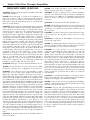
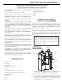
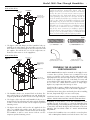
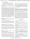
FLOW-THROUGH
FURNACE
HUMIDIFIER
Model 5000
Installation/Operating
Instructions
2
Model 5000 Flow Through Humidifier
FREQUENTLY ASKED QUESTIONS
ANSWER: This model will deliver 12 US Gallons (10 Imp.
Gallons, 45.5 Litres) per 24 hrs of operation..
QUESTION: Why use a flow-through style humidifier rather than
a drum style humidifier?
COMMENT: 24 Hrs of operation means continues humidifier
operation. This unit delivers sufficient moisture to humidify the
average home up to 3200 sq ft. The humidifier will ensure that
when your furnace is heating it is delivering humidified air to
your home.
ANSWER: This will depend on several factors including size of
home, type of furnace, and size of ducting; as well as personal
preference. However in order to use this model flow through you
will require at least 10" wide ducting where as our drum styles
will fit on 8" wide ducting.
COMMENT: Flow-through and rotating-drum style evaporative
furnace humidifiers will safely and efficiently humidify 90% of
homes which use forced air heating. As a manufacturer of both
styles there are pro’s and con’s to be considered when choosing
a flow through or drum style. A drum-style humidifier will
typically have a higher output when compared to a flow through
of equal size, however with today’s modern home construction
and insulation techniques the higher capacities are not required,
over humidification is something that should be well guarded
against. Another point to consider is the fact that a drum style
humidifier is 100% efficient (meaning that all the water supplied
to the unit is delivered to the air) where as the flow through styles
range anywhere from 30% to 40% efficient (meaning that for
every gallon of water delivered to the air 2 gallons will be allowed
to flow through). Today, indoor air quality (IAQ) is an issue on
everybody’s mind and the inefficiency of flow through
humidifiers is by design as the water flowing through serves to
flush away any unwanted minerals and such leaving only clean
water to be evaporated. The cost of maintaining (typically a
evaporator pad once a year) and operating a flow through style is
far less when compared to the cost of maintaining a drum style
humidifier to ensure healthy and efficient operation.
QUESTION: What type of furnaces will this humidifier work on?
ANSWER: The unit will work on most forced air furnaces which
incorporates a heating source, a supply duct, and a return duct.
COMMENT: The technology used in this humidifier to deliver
water to the air is not new, it is the simplest and easiest style a
bypass type evaporative humidifier. Your furnace fan creates a
pressure difference between the supply (hot) air and the return
(cold) air. By installing a bypass tube between the supply and return
air a small amount of air is forced (via the pressure difference)to
flow from the supply duct through the humidifier’s evaporator pad
and back into the return duct where it will mix with all the return
air from your home. As the hot air passes through the evaporator
pad it will “evaporator” moisture and deliver it to your home. What
will differ from furnace to furnace or home to home is how much
moisture or capacity you will get from the unit. There are many
factors which will affect this: How old is your home? How old is
your furnace? How well insulated is your home? For example, the
capacity of the unit is 12 US gallons per 24 hours of operation. This
is based on ARI standards (120°F hot air temp, 60°F water supply
temp, 0.5" static pressure difference between supply and return)
used by all humidifier manufacturers. If your furnace is a hi
efficiency or pulse type furnace the hot air temperature may be less
or the length of time the furnace burner is on may be less; therefore
as a rule of thumb we would say you would get approx 75% to
80% of the rated output. Generally speaking high-efficient furnaces
are used in homes which are very well insulated and therefore the
75% or 80% capacity will be more than enough to humidify the
home.
QUESTION: How much moisture does the humidifier deliver to
the air in my home?
QUESTION: How much water does this humidifier use?
ANSWER: This humidifier incorporates a restrictor which meters
the amount of water supplied to the unit. In a average home the
unit will use 37 US Gallons (31 Imp. Gallons, 140 Litres) per 24
hrs of operation.
COMMENT: Your furnace will not run continuously 24 hrs a day;
in an average home the 36 gallons will be used over a 3 day
period.
QUESTION: I’m replacing an old humidifier on my furnace can
I use the old components?
ANSWER: You should replace all the components to ensure good
operation. You may be able to utilize the existing duct cut outs for
the new installation (see section in the instructions.)
COMMENT: As a rule we like to see you change all the
components, particularly the water supply tube, as over time
minerals, solids, or sludge may have built up, these will very
quickly clog the water inlet of the flow through, or over time the
tube may have become worn or leaky. Replace the bypass duct
as well there may be secondary dampers unseen which will block
air or again there may be unseen wear which will cause air leaks.
Same with electrical components or wiring these may be
malfunctioning or worn out. If you have a humidifier which was
interlocked with your furnace (meaning the humidifier only came
on when the furnace came on) then the old transformer is getting
power from the internal furnace wiring. You should leave this
transformer and wiring in place; if this transformer is functioning
and it is 24 Volts AC, you may be able to utilize it to control the
new humidifier.
QUESTION: I’ve installed the humidifier on my furnace and it is
functioning properly but I do not feel anything and the humidistat
reading is not changing, is the humidifier working?
ANSWER: As long as there is hot air going through the humidifier
and there is water getting to the evaporator pad moisture is being
delivered to the air in your home.
COMMENT: All year, and especially during the winter months
when many combustion appliances are operating in your home,
fresh air is required to ensure a healthy environment for your
family. Do not think of your home as a sealed bubble, no matter
how well insulated. All houses breath (some more than others)
the cold outside air mixes with the air in your home constantly,
even when your furnace is not running. A furnace humidifier will
work to offset the constant effect the dry outside air has on your
home, and your home’s furnishings. Throughout the winter there
is a constant diminishing and replenishing of moisture levels in
the home, conditions inside and out rarely remain stagnant for
any length of time.
Model 5000 Flow Through Humidifier
3
INSTALLATION AND OPERATING INSTRUCTIONS:
MODEL 5000 FLOW THROUGH HUMIDIFIER
• READ THESE INSTRUCTIONS FULLY BEFORE INSTALLING
THIS HUMIDIFIER.
• SAVE THESE INSTRUCTIONS FOR REFERENCE.
• WHEN DRILLING OR CUTTING INTO DUCTING BE
EXTREMELY CAREFUL NOT TO DAMAGE AIRCONDITIONING COILS OR OTHER FURNACE APPARATUS.
• Measuring tape or ruler
• Medium-grit sand paper
• Pencil
• Tape
• THIS UNIT MUST BE INSTALLED ON 10” WIDE DUCTING
MINIMUM.
• FOR THIS UNIT TO OPERATE PROPERLY YOUR FURNACE
SHOULD ACHIEVE A HEATING TEMPERATURE OF AT LEAST
35°C IN ONE MINUTE. IF IT DOES NOT YOU MAY HAVE TO
PURCHASE A PRESSURE ACTIVATION SWITCH (SOLD
SEPARATELY)
•
DO NOT INSTALL THIS UNIT WHERE EXTREME
TEMPERATURES EXIST (BELOW 45°F – ABOVE 145°F).
• THIS UNIT REQUIRES A DRAIN TO ALLOW WATER TO
FREELY RUN OFF.
• FOR THIS UNIT TO OPERATE PROPERLY IT MUST BE
INSTALLED ON A FORCED AIR HEATING SYSTEM WITH A
SUPPLY DUCT and A RETURN DUCT.
• THE HUMIDIFIER BODY and THE BYPASS COLLAR DAMPER
ARE TO BE INSTALLED ON DUCTING ONLY. UNDER NO
CIRCUMSTANCES MOUNT EITHER COMPONENT TO THE
FURNACE BODY.
• ELECTRICAL WIRING, WATER SUPPLY and DRAIN TUBE
MUST NOT KINK OR COME INTO CONTACT WITH SHARP
EDGES OR HOT SURFACES.
• IF REPLACING AN EXISTING FURNACE HUMIDIFIER, WE
RECOMMEND YOU REPLACE ALL COMPONENTS TO
ENSURE PROPER HUMIDIFIER OPERATION.
• THE INSTALLATION OF THIS PRODUCT MUST COMPLY
WITH NATIONAL AND LOCAL ELECTRICAL, PLUMBING,
BUILDING, AND MECHANICAL CODES.
REQUIRED TOOLS
• Safety glasses
SELECTION OF LOCATION
TO MOUNT THE HUMIDIFIER
All bypass type furnace humidifiers rely on the pressure
difference which exists between the supply duct (hot air) and the
return duct (cold air) to create and air-flow through the
humidifier’s evaporator pad. The air will ALWAYS flow from HOT
(high pressure) to COLD (low pressure).
Selecting the proper location, and installing the humidifier
properly as intended by the manufacturer is imperative for the
proper operation of the humidifier – see illustrations below along
with the brief explanations as to what is a good installation and
what is not.
• INSTALLATION TIP: Before starting fully plan out the
installation. Check for the locations of the humidifier,
bypass collar and damper, the length and type of ducting
required, the water supply, the water drain, the electrical
wiring, and a constant 120 volt outlet to plug in the
transformer. This will ensure your installation goes as
easy and quickly as possible.
IDEAL INSTALLATION
Figure 1
SUPPLY DUCT
WARM AIR
RETURN DUCT
COLD AIR
10" wide duct minimum
Damper fully open
No more
than 30"
Bypass collar and
unit level
Bypass tube pulled
tight and cut to length
• Work gloves
• Electric drill
• Drill bits (3/8", 1/8", 5/64")
Water flowing to drain
• Tin snips
• Full size Philips or Roberstons screw driver
• Short handle Philips or Roberstons screw driver
• Adjustable wrench
• Utility knife
• Pliers
• Level
1. The humidifier body and bypass tube are installed at eye level,
easily accessible for installation and routine maintenance.
2. The space between the humidifier body and bypass tube are no
more than 30" to ensure maximum air flow through the humidifier.
3. The aluminum flex bypass tube are cut to the proper length
and pulled tight to ensure maximum air flow.
4
Model 5000 Flow Through Humidifier
4. The bypass damper is fully open.
5. The humidifier is mounted level on the duct.
6. There is nothing inside the duct behind the bypass collar and
damper or the humidifier body.
1. The humidifier body and bypass collar and damper are not
level. This will restrict air flow through the humidifier as well
as create uneven air-flow over the evaporator pad and
activating sensors.
7. The humidifier and bypass collar and damper are level.
2. The aluminum flex bypass tube is not cut to length and is
sagging. This will result in reduced air-flow over the evaporator
pad and will affect the performance of the activating sensors.
BAD INSTALLATION
BAD INSTALLATION
Figure 2
SUPPLY DUCT
WARM AIR
RETURN DUCT
COLD AIR
Figure 4
SUPPLY DUCT
WARM AIR
RETURN DUCT
COLD AIR
Bypass damper
not open
Air conditioning
A-frame blocking
the air flow
Unit installed
too low
Unit draining
to a bucket
1. The humidifier body is installed too low and will be difficult to
work on.
2. The humidifier body and bypass collar and damper are not
level. This will restrict air-flow through the humidifier as well
as create uneven air-flow over the evaporator pad and
activating sensor.
3. The bypass damper is not fully open, This will restrict air flow
through the humidifier and reduce output.
4. The humidifier is being drained to a bucket rather than a
proper drain. This will result in damage to the home.
BAD INSTALLATION
Figure 3
SUPPLY DUCT
WARM AIR
RETURN DUCT
COLD AIR
Bypass collar and
humidifier not parallel
Sagging bypass tube
1. The bypass collar and damper are installed in front of the
furnace’s air-conditioning coils. This will not only greatly affect
the performance of the humidifier and cause malfunctions in
the activating sensors, the homeowner risked damaging the
air-conditioning coils. This would also be the case if the
humidifier were installed in front of the air-conditioning coils.
• INSTALLATION TIP: In this type of installation the
installer should mount the bypass collar and damper at
least 6" above the air-conditioning coils and use hard
metal ducting and elbows (sold separately) rather than
the flex tube. While the humidifier and bypass collar and
damper will not be level the use of hard ducting rather
than the flex ducting will make up for any restrictions or
turbulence which would occur in aluminum flex tube.
Model 5000 Flow Through Humidifier
BAD INSTALLATION
Figure 5
SUPPLY DUCT
WARM AIR
RETURN DUCT
COLD AIR
Bypass tube and
humidifier installed
on the same duct
5
• INSTALLATION TIP: In this type of installation the
installer should have mounted the bypass collar and
damper in the most convenient location to run ducting
back to the unit. If for some reason it was necessary to
run ducting like this, hard metal ducting and elbows
(sold separately) rather than the flex tube should be
used; the installer should also try to find the most direct
route to duct. While the humidifier and bypass collar
and damper may be more than the recommended 30",
apart the use of hard ducting rather than the flex ducting
will make up for any restrictions or turbulence which
would occur in aluminum flex tube. Flexible ducting
may be the most convenient for installation purposes
however when it comes to air-flow it is highly restrictive
(see fig 7.), its use should be kept to a minimum and
when used it should be pulled as tight as possible.
Figure 7
1. The bypass collar and damper and the humidifier body are
installed on the same ducting. This unit will not operate at all,
there will be no air-flow through the unit, the air pressure will
just equalize. This will be the case if both components are
mounted on the return or on the supply duct.
FLEX LOOSE
EQUIVALENT LENGTH = 9 FEET
FLEX PULLED TIGHT
EQUIVALENT LENGTH = 2 1/2 FEET
HARD DUCTING ELBOW (90°)
EQUIVALENT LENGTH = 10 FEET
FLEX DUCTING ELBOW (90°)
EQUIVALENT LENGTH = 30 FEET
BAD INSTALLATION
Figure 6
SUPPLY DUCT
WARM AIR
RETURN DUCT
COLD AIR
Bypass required is
more than 30" and
installer is using
flex tube
Unit is not level
Bypass collar and
humidifier not parallel
PREPARING THE HUMIDIFIER
FOR INSTALLATION
Model 5000 humidifiers may be mounted on the supply (hot air)
or return duct (cold air), however we recommend for safety
reasons you install it on the return duct, this will minimize the
high temperature the unit and components are exposed to. Only
install on the supply duct (hot air) if absolutely necessary and
ensure that the water supply, drain tube, or any other component
do not come into contact with hot surfaces or sharp edges.
Replace any component at the first sign of wear.
CAUTION: When cutting or drilling into ducting take care not to
damage any air-conditioning coils or other furnace apparatus
1. The humidifier body is not mounted level on the duct. The
water which flows to the distribution tray and through the
evaporator pad will all run down one side of the evaporator pad.
2. The bypass collar and tube and humidifier body are not
mounted level. This will restrict air flow through the humidifier
as well as create uneven air-flow over the evaporator pad and
activating sensors.
3. The bypass tube used is well over the 36" supplied, the flex
tube is not pulled tight and the most direct route to the
opposite duct was not taken. This will restrict air flow through
the humidifier as well as create uneven air-flow over the
evaporator pad and activating sensors
CAUTION: Wear safety glasses and work gloves when installing
this unit; sharp metal edges can cause severe injury.
CAUTION: Turn the furnace off before starting this installation.
STEP #1: RIGHT HAND DUCTING OR LEFT HAND DUCTING
Depending on your furnace, or for the convenience of your
installation it may be necessary to convert the humidifier from
right hand ducting or left handing ducting. Follow the steps below
to switch the side which the bypass duct will attach to the unit.
SWITCH THE DUCTING ONLY IF YOUR APPLICATION
REQUIRES IT.
1. Remove the humidifier front cover, which is secured in place
with a 10-24 plastic thumb screw at the bottom of the cover.
Model 5000 Flow Through Humidifier
6
Tilt the cover away from the body slightly (approx. 1/2") and
then lift up the cover to free the hooks at the top of the unit.
2. Remove all loose components packaged inside and any
packaging. With a firm pull, disconnect the water tube from the
water nozzle and remove the evaporator pad assembly by sliding
it toward the top of the humidifier, then lifting it out. (fig 8.)
and any packaging. With a firm pull, disconnect the water tube
from the water nozzle and remove the evaporator pad assembly
by sliding it toward the top of the humidifier, then lifting it out.
(fig 8.) The humidifier comes with a mounting template. Ensure
the cabinet is installed level for proper operation.
CAUTION: When cutting or drilling into ducting take care not to
damage any air-conditioning coils or other furnace apparatus
CAUTION: Wear safety glasses and work gloves when installing
this unit. Sharp metal edges can cause severe injury.
1. Use adhesive tape to affix the template onto the duct in the
selected location. Use the level line to the template and a level
to ensure the cabinet will be level.
2. Drill the four marked cabinet-mounting holes on the template
using a 1/8" drill bit (not supplied)
Figure 8
3. Using a 3/8" drill bit (not supplied) drill a hole inside the
rectangle marked “HUMIDIFIER CUT OUT”.
3. Remove the two #6 screws which hold the humidifier side in
place (a short handled screw driver will give you easier access
to the screws) (fig 9.)
4. Using the 3/8" hole drilled in step 3 as a starting point, cut out
the Humidifier Cut Out area marked on the template using tin
snips (not supplied). Cut on the outside of the line to ensure a
proper fit.
5. Mount the humidifier cabinet on the duct with 4 of the screws
from the installation package. Level the humidifier before
tightening the screws. (fig. 11)
Figure 9
4. Lift the humidifier side out of the right hand position, turn the
part and position it on the other side of the humidifier. (fig. 10)
Figure 11
6. Install the evaporator pad assembly by hooking the slanted tabs
on the evaporator pad frame onto the tabs on the back of the
humidifier cabinet. MAKE SURE THE OPEN END OF THE
NOZZLE IS FACING YOU.
7. Firmly insert the water tube into the nozzle.
STEP #3: MOUNTING THE BYPASS COLLAR AND DAMPER
Figure 10
5. Use the two screws removed in step 3 to secure the humidifier
side in the left hand side.
STEP #2: MOUNTING THE HUMIDIFIER ON THE DUCT
If you have not already done so, remove the humidifier cover,
which is secured in place with a 10-24 plastic thumb screw at the
bottom of the cover. Tilt the cover away from the body slightly
(approx. 1/2") and then lift up the cover to free the hooks at the
top of the unit. Remove all loose components packaged inside
The humidifier comes with a collar and damper mounting
template. If possible ensure that the bypass collar will be level to
the humidifier duct connection. Try to keep the bypass collar
within 30" of the humidifier.
CAUTION: When cutting or drilling into ducting take care not to
damage any air-conditioning coils or other furnace apparatus
CAUTION: Wear safety glasses and work gloves when installing
this unit. Sharp metal edges can cause severe injury.
1. Use adhesive tape to affix the bypass template onto the duct
in the selected area.
Model 5000 Flow Through Humidifier
7
2. Drill three marked bypass collar mounting holes on the
template using a 1/8" drill bit (not supplied)
3. Using a 3/8" drill by (not supplied) drill a hole inside the
circular area marked collar cut out.
4. Using the 3/8" hole drilled in step 3 as a starting point cut out
the Collar Cut Out area marked on the template using tin snips
(not supplied)
5. Mount the bypass collar and damper (fig. 12) using the
remaining three screws from the installation package. The air
damper should be mounted in the open position. The top
screw secures the damper.
Figure 13
2. Prepare the end (fig 14) of the 1/4" tubing for water connection
to the humidifier (All required hardware supplied in the
saddle-valve kit in the installation package).
Brass nut
Brass
insert
Plastic ferrule
Figure 14
Plastic water tube
3. Make the tube connection to the humidifier using an
adjustable wrench (not supplied) to tighten the nut. (fig 15)
Figure 12
6. Slide one of the 6" spring clamps supplied over one end of the
bypass tube. Slide this same end of the bypass tube over the
flange of the collar and secure it with the spring clamp.
7. Slide the other 6" spring clamp over the other end of the
bypass tube. Slide this end of the bypass tube onto the
humidifier and secure it with the spring clamp.
8. Ensure the bypass is pulled tight and that any ripples are kept
to a minimum and no sagging is occurring. Cut any excess
bypass tube off if necessary using tin snips (not supplied).
• INSTALLATION TIP: If replacing an existing humidifier
which has been installed on your furnace you may be
able to use the existing cut-outs, however replace the
components, bypass collar and damper and bypass
tubing. The majority of furnace humidifiers use 6"
ducting for bypass. The cutout for the humidifier will
more than likely be different. If replacing a drum style
the cutout will not be big enough, and if replacing an old
flow through you may have to first install a separate
metal plate (not supplied) to cover the existing hole as it
may be too big. Before you mount the separate metal
plate (not supplied) attach the humidifier cabinet
template to it and drill all necessary holes and make the
required cutouts. Keep in mind the points listed above
about length and level of ducting; it maybe best to cover
all existing holes and start fresh.
STEP #4: WATER SUPPLY AND DRAINAGE CONNECTION
WARNING: Make sure the evaporator pad is installed correctly
BEFORE you make the water connections.
1. SAND BOTH ENDS (fig 13) of the water supply tube. FAILURE
TO DO SO MAY RESULT IN LEAKS.
Figure 15
4. Select the most convenient location for connecting the selfpiercing needle valve on a cold water pipe. Connect the needle
valve as shown (fig 16). The hardware shown is supplied in the
needle-valve kit. Once the the valve is connected to a pipe as
shown, TURN THE VALVE CLOSED ALL THE WAY, and then
open so water can flow to the humidifier. Check all fittings for
leaks and tighten/repair if necessary.
Figure 16
Brass insert
Plastic
ferrule
Brass nut
Plastic
water tube
Model 5000 Flow Through Humidifier
8
5. YOU MUST RUN A
DRAINAGE TUBE FROM
THIS UNIT. Select a
convenient location for
running the 1/2" drainage
tube, 15 ft supplied.
Before you connect the
tubing to the drain fitting
on the bottom of the
unit, slip the 1/2" hose
clamp (supplied) over the
tubing (fig 17). Push the
tubing over the fitting and
secure in place with the
hose clamp.
Figure 17
3. Using the 3/8” hole drilled in step 2 as a starting point cut out
the Humidistat Cut Out area using tin snips (not supplied)
4. Locate the humidifier terminal panel on the side of the
humidifier cabinet, behind the bypass tube. Connect the two
ends of the transformer lead wires to the humidifier terminals
marked “24 VAC IN”. (fig 19)
5. Run the transformer lead
wires from the humidifier to the
center of the hole you created
in step 3. Note the length of the
wire from the humidifier to this
point, and add approximately 2
more inches to this length. At
this point on the wire, carefully
cut the insulation between the
conductors and separate them
approx 3” (fig 20)
CAUTION: Drain tubing
must not kink or come
into contact with sharp
edges or hot surfaces.
6. Cut on the conductors and
strip (approx 3/4") the insulation
from both ends (fig 21).
STEP #5: ELECTRICAL INSTALLATION
The humidistat supplied with the Model 5000 Humidifier can be
either duct or wall mounted. Duct mounting the humidistat is the
easiest installation. A wall mount provides more convenient control
of the humidifier and depending on your heating/ventilation
system may provide a more accurate indication of the relative
humidity level in your home. When wall mounting the humidistat
you should choose a central location (close to the furnace
thermostat) and you may be required to purchase extra low voltage
wire to run back to the humidifier. 20 ga will be sufficient.
DUCTING MOUNTING THE HUMIDISTAT
AND POWER CONNECTION TO THE HUMIDIFIER
The humidistat is packaged at the factory ready for wall
mounting. You will have to convert it to duct mounting. Refer to
fig. 18, when duct mounting the humidistat must be located
upstream (approx 6”) from the humidifier or bypass tube on the
return duct. Select a convenient location to mount the humidistat
on the return duct. The unit comes with a humidistat mounting
template. THIS TEMPLATE IS FOR DUCT MOUNTING THE
HUMIDISTAT ONLY.
Figure 19
7. From the humidistat assembly
included with your unit remove
the humidistat. Gently pull off
the knob and label, and remove
the humidistat cover (fig 22 )
8. Remove the humidistat control from the base plate by undoing
the two screws holding it in place.
9. In the duct mounting application the base plate is used as the
front cover, reattach the humidistat control to the base plate
(fig 18).
10. Using the two 90-degree terminals included with the
humidistat kit, attach the two stripped wire ends of the
transformer leads that you cut in step 6 to the humidistat
terminals.
11. Mount the humidistat assembly into the duct cut out made in
step 3. Secure in place with four screws provided in the
humidistat kit (fig 17).
12. Remove the paper backing from the humidistat label and
apply onto the face plate. Install the knob onto the humidistat
control shaft.
Humidistat
Base
Figure 20
Figure 21
Label
WALL MOUNTING THE HUMIDISTAT
AND POWER CONNECTION TO THE HUMIDIFIER
Low Voltage
Wire
Figure 18
1. Drill the 4 marked humidistat mounting holes on the template
using the 5/64” drill bit (not supplied)
2. Using a 3/8” drill bit (not supplied) drill a hole inside the
rectangle marked Humidistat Cut Out.
CAUTION: When cutting or drilling in a wall take care not to hit
any of home’s electrical or other utilities.
1. Select a central location in the home at eye level on an inside
wall. The best place is next to the furnace’s thermostat.
2. Drill a small hole to fish low voltage wire (not supplied) out of
and leave approximately 6” of wire leads outside of the hole
for connection to the humidistat. Guide the other end of the
low voltage wire to the humidifier on the furnace.
3. Locate the humidifier terminal panel on the side of the
Model 5000 Flow Through Humidifier
humidifier cabinet, behind the bypass tube. Connect the two
ends of the transformer leads to the humidifier terminals
marked “24 VAC IN”
4. At any point along the transformer leads (most convenient
location to connect the transformer low voltage wire to the
humidistat low voltage wire) carefully cut the insulation
between the two conductors and separate them approx 3” (fig
20).
5. Cut one of the conductors and strip (approx. 3/4”) the
insulation from both ends ( fig 21).
6. Using wire nuts (not supplied), connect the two stripped ends
of the low voltage wire leads from the humidistat to the two
ends of the stripped transformer leads prepared in step 5.
7. Returning to the humidistat location, remove the cover plate
from the humidistat. Feed the 6” of low voltage wire through
the 3/8” hole in the humidistat base plate. Mount the
humidistat to the wall using four screws provided in the
humidistat kit (fig 22).
Base
Humidistat
Cover
Label
9
STEP #6: TESTING THE INSTALLATION
If you have not already replace the front cover of the humidifier
and secure in place using the plastic thumb screw.
1. Make sure all water connections are secure and do not leak. Also,
ensure that all components are secure and installed correctly.
2. Plug in the 24-Volt transformer into a constant 120-Volt power
source (an outlet which cannot be shut off via a wall switch).
3. Turn up the humidistat to the maximum setting 50% +. This
ensures the humidistat is calling for humidity. If the humidistat
is not calling for humidity at the BEGINNING of the furnace
cycle the humidifier will not turn on, if you turn up the
humidistat in the middle of the furnace cycle the humidifier
will wait until the NEXT cycle to turn on.
4. Turn on the power to your furnace and turn up the thermostat
so that the furnace cycles on in heating mode.
• OPERATING TIP: Most furnaces will take a few
minutes to allow heat to build up before the furnace fan
will run. The “HUMIDISENSE” control contained in the
humidifier will wait until it senses your furnace fan
blowing hot air. If only your furnace fan is running the
unit should not turn on. The “HUMIDISENSE” will not
turn the humidifier on until is senses a temperature rise
of 4°C and the air temperature is over 30°C. This ensures
the efficient use of water.
5. Depending on your furnace type the unit should turn on
within approx 60 seconds of the furnace entering the
HEATING cycle. You will know because the green
“HUMIDISENSE” LED on the front of unit will turn on (fig 24.)
If the unit does not turn on refer to the trouble shooting
section in the Maintenance Guide.
Figure 22
8. Using the two 90-degree wire terminals (included in the
humidistat kit) connect the end of the low voltage wire to the
humidistat terminals.
Green
Humidisense
LED
9. Replace the cover. Remove the paper backing from the
humidistat label, and apply to the face of the cover. Install the
knob onto the humidistat control shaft.
CHECKING THE ELECTRICAL CONNECTION,
DUCT MOUNT OR WALL MOUNT HUMIDISTAT.
Figure 24
Once the wiring is complete you should have all the components
wired in series (a continuous loop) as shown in fig. 23. Use the
insulated staples included in you installation package to secure
any loose wiring.
Figure 23
120V
Electric
Source
Humidistat
24V
Transformer
Humidifier
6. Once the unit has been running for approx 3-4 minutes you
will see a small amount of water trickling out of the drain tube.
If the unit has turned on and the green light is on but no water
is trickling refer to the trouble shooting section in the
Maintenance Guide.
• OPERATING TIP: In order to ensure efficient water use,
ensure water will not blow off the evaporator, and to
protect the humidifier’s solenoid valve there is an orifice
fitting installed on the inlet of the solenoid valve. This
fitting restricts the amount of water flowing to the unit,
which will vary depending on your house’s water
pressure. On average this fitting will allow approx 300600 ml of water to flow in 5 minutes of humidifier
operation.
10
Model 5000 Flow Through Humidifier
7. After about 5 minutes of running turn your thermostat down
so the furnace cycles off. IT IS IMPORTANT TO ALLOW THE
FURNACE TO CYCLE OFF VIA THE THERMOSTAT AND NOT
THE MAIN FURNACE SWITCH, AS ALL FURNACES WILL
RUN A COOL DOWN TO ALLOW HEAT TO CIRCULATE
OUT OF THE FURNACE HEATING CHAMBER. The
humidifier will sense the temperature drop and shut off (this
will occur depending on your furnace, from 60 seconds before
the furnace shuts of to 60 seconds after the furnace shuts off.)
You will know the humidifier has shut off because the green
“HUMIDISENSE” LED on the front of the humidifier will shut
off. (fig. 24) The off cycle of the “HUMIDISENSE” CONTROL
IS ADJUSTABLE. See section “CUSTOMIZING HUMIDISENSE
TO YOUR FURNACE” below if the humidifier does not shut
off with your furnace.
• OPERATING TIP: Most furnaces will take anywhere
from 30 seconds to 2 minutes to complete a off cycle.
First the furnace will sense that the thermostat is satisfied
then the furnace burner will shut off. The furnace fan will
continue to run (the amount of time depending on how
your furnace is set up) this allows the heat to circulate
out of the furnace heating chamber and assures efficient
use of heating fuel.
YOU MUST CAREFULLY FOLLOW THE FOLLOWING STEPS TO
CHANGE THE CONTROL’S SET POINT:
1. Determine if the humidifier is not shutting off when the
furnace shuts off
2. Read the explanation of the different settings below and
determine which dip switch position you require.
3. The humidifier must be energized but NOT running in order
to change the dip switch position. If your humidifier has not
shut off after a furnace cycle, turn DOWN the furnace’s
thermostat (so the furnace shuts off and will not come back
on). UNPLUG the humidifier for a few minutes and allow the
humidifier to cool down, then plug the humidifier back in.
Now the humidifier should be plugged IN, the humidistat
turned UP all the way, your furnace should be OFF, and the
humidifier should NOT be running.
4. With the furnace OFF, Change the dip switch position to the
desired location.
5. AFTER you have changed the dip switch location UNPLUG
THE HUMIDIFIER FOR 1 MINUTE.
6. After the humidifier has been unplugged for 1 MINUTE, Plug
the humidifier back in and WAIT ANOTHER MINUTE.
HUMIDIFIER OPERATION
7. The control set point has now been changed. Turn UP the
furnace thermostat and check humidifier operation.
CUSTOMIZING HUMIDISENSE TO YOUR FURNACE
HUMIDISENSE CONTROL SETTINGS: FACTORY SETTING (FIG. 25.)
The HUMIDISENSE control is a temperature and time based
control designed to cycle the humidifier ON and OFF in
sequence with your furnace’s cycles. As there are many different
homes and styles of furnaces the HUMIDISENSE control has 4
self contained adjustable temperature set points to control the
humidifier’s cycles, as well there is a redundant safety circuit
which with the use of a pressure switch (sold separately) can be
used to bypass the temperature control feature and cycle the
humidifier based on the furnace fan’s cycle.
Depending on your furnace or other factors present in your
home (use of secondary supplemental heating, HVR’s, ERV’s,
etc) it may become necessary to change the setting of the
control to ensure the humidifier is shutting off when your
furnace cycles off. This is easily done by changing the dip switch
(located on the lower side of the control housing see below)
positions, using a small screw driver. NOTE: Only change the
setting IF REQUIRED.
The control comes from the factory set
with the criteria indicated below.
Humidifier ON : A temperature rise of 4°C
in one minute and a temperature greater
than 30°C
Figure 25
Humidifier OFF: A temperature drop of
2°C in one minute and a temperature less
than 45°C
• This setting will meet the requirement of 85% of the furnaces
in the market today. It will provide the required humidifier
control on furnaces ranging from high to low efficiency. You
should only change the setting if required.
OPTIONAL SETTING # 1 (FIG. 26.)
Humidifier ON : A temperature rise of 4°C
in one minute and a temperature greater
than 30°C
Humidifier OFF: A temperature drop of
2°C in one minute and a temperature less
than 35°C
Dip Switch
• This setting will be useful when you find that
the humidifier is shutting off too early or if the
humidifier is cycling off in the middle of a
furnace cycle. If your furnace is multi-speed (the furnace fan will
change speed during the heating cycle.) or if you have a highefficiency furnace, where the furnace burner will cycle ON and
OFF during the heating cycle in order to save energy.
Figure 26
Model 5000 Flow Through Humidifier
OPTIONAL SETTING # 2 (FIG27.)
Humidifier ON : A temperature rise of 4°C
in one minute and a temperature greater
than 30°C
Humidifier OFF: A temperature drop of
2°C in one minute and a temperature less
than 55°C
11
have the same ON temperature requirements. This is ensuring an
efficient use of water as there is a minimum air temperature to
efficiently evaporate water. As well if for some reason you wish to
bypass the temperature feature and have the humidifier operate
when fan operates you may choose this option. This option
requires the purchase and installation of a separate pressure
switch (fig 30). Installation instructions for the pressure switch are
included with the kit.
• This setting will be useful when you find
the humidifier is not turning off when your
furnace has cycled off. Typically this will
occur because the furnace’s cool down cycle is short and the
furnace is shutting off when there is still hot air circulating through
the ducts. As well this will be seen when the furnace is located in
an enclosed space and as a result the ambient temperature is high.
Figure 27
OPTIONAL SETTING # 3 (FIG. 28.)
Humidifier ON : A temperature rise of 4°C
in one minute and a temperature greater
than 30°C
Humidifier OFF: A temperature drop of
2°C in one minute and a temperature less
than 65°C
• This setting will be used when option # 2
(55°C off temp) does not work. You will find
this when a furnace does not have a cool
down cycle at all, on older model furnaces. This could be
occurring when the furnace is older and has short off cycles or if
the furnace is located in a tight enclosed space and the ambient
temperature is very high.
Figure 28
• OPERATING TIP: Depending on the type of furnace and
installation, you may notice that after the humidifier has
shut off and the furnace shuts off the humidifier will turn
back on. This is occurring because the control is sensing
residual heat from the heat exchanger after the furnace has
shut off. If you are experiencing this you should change the
control setting until the problem is resolved. The
temperature at which your furnace shuts off is too close to
the control’s OFF temperature. It may be beneficial to have
the control set to the higher OFF temperature (55°C or
65°C). However it is important to note ONLY CHANGE
THE CONTROL SETTING IF NECESSARY.
REDUNDANT SAFETY CIRCUIT SETTING –
PRESSURE SWITCH CONTROL (NOT SUPPLIED) (FIG. 29)
Figure 30
Pressure Switch
CONTROLLING THE HUMIDITY LEVEL
AND HUMIDIFIER OPERATION
HUMIDIFIER START UP
When you first plug in the 24 Volt transformer and turn on your
humidifier you may hear a click. This is the power getting to the
control’s relay. As well if you adjust the humidistat UP or DOWN
and past the sensed humidity level you may hear the control’s
relay clicking. This is normal as the humidistat is just an ON/OFF
switch, every time the humidistat is turned DOWN the power is
cut to the HUMIDISENSE control.
When starting up the humidifier for operation:
1. Make sure the transformer is plugged in and the water supply
is turned on.
2. Turn the humidistat up high, so it is calling for humidity.
Humidifier ON: When pressure switch
senses air-flow in the furnace duct
3. Turn your furnace thermostat UP so the furnace cycles ON.
Humidifier OFF: When pressure switch
senses no air-flow in the duct.
4. Once the HUMIDISENSE control senses heat the humidifier will
turn ON. You will know because the green “HUMIDISENSE”
LED (fig. 24) on the front of the humidifier will turn ON.
• This setting can be used if for some reason
the above 4 different control setting fail to
shut off the humidifier. This is more than
Figure 29
likely occurring as a result of a non-standard
heating system, some sort of supplement
heating, improper humidifier installation, improper furnace
operation, or for some other unforeseen circumstance. This
option may also be used if for some reason the humidifier will not
turn on, this could be occurring because the furnace is not
providing enough heat or it is not providing the required
temperature rise fast enough. All four of the above control setting
5. After a few moments you should hear water trickling through
the drain.
6. After your furnace has completed the heating cycle and shut
off (by the thermostat) the humidifier will cycle OFF. You will
know because the green “HUMIDISENSE” LED (fig. 24) on the
front of the humidifier will turn OFF
CONTROLLING THE HUMIDITY LEVEL
A humidistat is supplied with this humidifier to control the
amount of moisture added to the air in your home. It will sense
12
Model 5000 Flow Through Humidifier
the relative humidity level in the air and work as the main
ON/OFF switch to control the humidifier, regardless of whether
your furnace is on or not.
BYPASS AIR ADJUSTMENT, SUMMER
SHUTDOWN, AND YEARLY MAINTENANCE
At the beginning of the heating season it may take sometime to
build up the relative humidity level in your home to the desired
level. For the first few weeks turn the humidistat up high to ensure
the humidifier will turn on with every furnace cycle; after you feel
that you have achieved the desired relative humidity level turn the
humidistat down until it cycles the humidifier OFF. The humidifier
will then work to maintain the relative humidity at that level.
BYPASS AIR ADJUSTMENT
ACHIEVING AND MAINTAINING A HUMIDITY LEVEL
Outside conditions are the primary factor affecting the humidity
level in your home; the colder it gets outside the less moisture the
outside air will have, your home brings in that outside air and the
humidifier will work to add moisture to it. As outside conditions
change the humidity level in your home will change as well.
Other factors which will affect humidity levels in the home
include how many air-changes are occurring, the amount of
people occupying the home, air leaks, the use of showers,
exhaust fans, HRV’s, and the use of a fireplaces or wood stoves.
For more information on achieving a humidity level and or
maximizing the output of the humidifier please see the
Maintenance and Trouble Shooting Guide.
Sometimes there can be a static pressure differential that may
cause an excess of air to flow through the bypass tube, causing
less airflow through the distant heat outlets in the house. It may
also blow water off the evaporator bad. In either case the air
damper installed with the bypass collar should by gradually
closed until the condition is corrected. To close the damper
loosen the top screw and lift up on the damper and turn closed
to the desired position. Damper adjustment is another way of
adjusting the amount of humidity being added to the house (the
less air bypassed the less humidity will be added.)
SUMMER SHUT DOWN
At the end of the heating season complete the following steps.
1. Turn the humidistat off.
2. Unplug the transformer.
3. Close off the water supply at the saddle valve.
4. Close the bypass damper.
SAFELY OPERATING A FURNACE HUMIDIFIER
YEARLY MAINTENANCE AND WINTER START UP
Proper control of the relative humidity level in the home is key to
ensuring good IAQ (Indoor Air Quality) for your home as well as
protecting against moisture damage.
For detailed recommended maintenance schedule refer to the
Maintenance and Trouble Shooting Guide.
Although a relative humidity environment of 45-50% may be
desirable, setting your humidistat at that point when outside air
temperatures are below 30°F can cause condensation on
windows and walls. Continued condensation for extended
periods of time may result in structural damage. Use the chart
below as a guide for maximum relative humidity settings at
different outdoor air temperatures.
OUT SIDE AIR TEMPERATURE MAXIMUM RELATIVE HUMIDITY SETTING
-20°F /-30°C
15%
-10°F /-25°C
20%
0°F / -20°C
25%
+10°F/-10°C
30%
+20°F/-5°C
35%
ABOVE +20°F/0°C
40%
If condensation continues to form on windows at these settings
reduce the humidistat setting by successive 5% increments. After
each reduction in setting allow 6 hours for equilibrium to be
reached before readjustment.
If condensation is consistently forming on your windows or if the
relative humidity level being sensed by the humidistat is consistently
different than the relative humidity level in the home then you may
want to consider changing the location where the humidistat is
mounted. If duct mounted, move the humidistat to a central
location, near the furnace thermostat. If after moving the humidistat
the condition persists turn OFF the water supply at the needle valve,
turn the humidistat off and consult a qualified HVAC service person.
When your house is unoccupied for longer than 3 days during
the winter months always set the humidistat down to 15% so that
severe weather during you absence will not result in
condensation which might cause damage in your home.
At the beginning of the heating season complete the following steps.
1. Inspect the water supply tube, water drainage tube, and
Electrical wiring replace if required
2. Plug in the transformer.
3. Turn on the water supply at the saddle valve and check for
any leaks.
4. Open the bypass damper.
5. Test the operation of the humidifier and check for any leaks
and complete any necessary repairs.