1
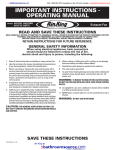
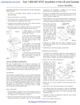
::kitchensource.com
2
Call 1-800-667-8721 anywhere in the US and Canada
Furnace Humidifier
FREQUENTLY ASKED QUESTIONS
Question: What type of furnaces will this humidifier work on?
Answer: The unit will work on most forced air furnaces
incorporating a heating source, a supply duct, and a return duct
at least 8” in width.
Comment: The technology used in this humidifier to deliver
moisture to the air is the simplest and easiest style, a bypass type
evaporative humidifier. Your furnace fan creates a pressure difference
between the supply air (hot, high pressure) and return air (cold, low
pressure). By installing a bypass tube between the supply and return
duct a small amount of air is forced (via the pressure difference) to
flow from the supply duct through the humidifier’s evaporator pad
and back into the return duct. What will differ from furnace to
furnace or home to home is how much moisture or capacity you will
get from the unit. There are several factors which will affect this, how
old is your home, how old is your furnace, how well insulated is your
home. For example, the capacity for this unit is 15 US gallons per 24
hrs of operation. This is based on ARI standards (120’F hot air temp,
60’F water supply temp, 0.5” static pressure difference between
supply & return duct), used by all humidifier manufacturers. If your
furnace is a hi efficiency or pulse type furnace the hot air
temperature may be less, or the length of time the furnace burner is
on may be less; therefore as a rule of thumb we would say you
would get approx. 75% to 80% of rated output.
Question: How much moisture does the humidifier deliver to
there may be unseen wear. The same goes for electrical
components or wiring these may be malfunctioning or worn out.
Note: If you have a humidifier which was interlocked with your
furnace (meaning the humidifier only came on when the furnace
came on) then the old transformer is wired in with your furnace.
Do not attempt to disconnect this transformer from the furnace
only disconnect the low voltage side wires for the humidifier and
tape over the terminals.
Question: I’ve installed the humidifier on my furnace and it
is functioning properly but I do not feel anything and
humidistat reading is not changing, is the humidifier working?
Answer: As long as there is hot air going through the humidifier
and there is water pan and the drum assembly is getting wet then
moisture is being delivered to the air in your home.
Comment: All year, and especially during the winter months
when many combustion appliance are operating in your home,
fresh outdoor air is required to ensure a healthy environment for
your family. Do not think of your home as a sealed bubble, no
matter how well insulated, all homes breath (some more than
others). The cold dry outside air is mixing with the air in your
home constantly, even when your furnace is not running. A
furnace humidifier will work to offset the constant effect the dry
outside air has on your home, and your home’s furnishings.
Throughout the winter there is a constant diminishing and
replenishing of moisture levels in the home, conditions inside and
out rarely remain stagnant for any length of time.
the air in my home?
Answer: This model will deliver 15 US Gallons (12.5 Imperial
gallons, 57 litres) per 24 hours of operation.
Comment: 24 hours of operation means at design conditions; your
furnace will only deliver the required hot air (120’F) when it is on.
Your furnace should not cycle more than 1/3 of the time so the 24
hours of humidifier operation may take up to 3 days to complete.
Question: How much water does this humidifier use?
Answer: This humidifier is 100% efficient, meaning all the water it
uses is delivered to the air to humidifier your home. It will use 15
US gallons (12.5 Imperial gallons, 57 litres) per 24 hrs of operation.
Comment: As mentioned above 24 hours of operation means at
design conditions – your furnace will only deliver the required
hot air (120’F) when it is on. Your furnace should not cycle more
than 1/3 of the time so the 24 hours of humidifier operation may
take up to 3 days to complete.
Installation
• READ THESE INSTRUCTIONS FULLY BEFORE INSTALLING
THIS PRODUCT.
• SAVE THESE INSTRUCTIONS FOR REFERENCE.
• SHUT THE WATER OFF BEFORE WORKING ON THE HUMIDIFIER.
• SHUT THE POWER OFF BEFORE WORKING ON THE
HUMIDIFIER.
• TAKE PRECAUTION WHEN CUTTING OR HANDING METAL
PCS. (CUT DUCT WORK), SHARP EDGES CAN CAUSE
SERIOUS INJURY.
• WHEN DRILLING OR CUTTING INTO DUCTING BE
EXTREMELY CAREFUL NOT TO DAMAGE AIRCONDITIONING COILS OR OTHER FURNACE APPARATUS.
• THIS UNIT MUST BE INSTALLED IN 8” WIDE DUCT
MINIMUM.
• DO NOT INSTALL THIS UNIT WHERE EXTREME TEMPERATURES
EXIST (BELOW 8˚C / 45˚F OR ABOVE 63˚C / 145˚F).
Question: I’m replacing an old humidifier on my furnace • THIS UNIT IS NOT SUPPLIED WITH A DRAIN TUBE.
can I use the old components?
Answer: You should replace all the components to ensure good
operation. You may be able to utilize the existing duct cut outs for
the new install however some reworking may be required.
Comment: As a rule we like to see you change all the
components, particularly the water supply tube. As over time
minerals, solids, or sludge may have built up, these will very
quickly clog the water inlets, or over time the tube may have
become worn or leaky. Replace the bypass duct as well, there
may be secondary dampers unseen which will block air or again
HOWEVER WE DO RECOMMEND YOU PURCHASE AND
INSTALL A 1/2” DRAIN TUBE (SEE SECTION INSTALLATION
INSTRUCTIONS) TO PROTECT AGAINST WATER
OVERFLOW.
• FOR THIS UNIT TO OPERATE PROPERLY IT MUST BE
INSTALLED ON A FORCED AIR HEATING SYSTEM WITH A
SUPPLY DUCT AND RETURN DUCT.
• THE HUMIDIFIER AND THE BYPASS COLLAR DAMPER ARE
TO BE INSTALLED ON DUCTING ONLY. UNDER NO
CIRCUMSTANCES MOUNT ANY COMPONENT TO THE
FURNACE BODY.
Air King at ::kitchensource.com
::kitchensource.com
Call 1-800-667-8721 anywhere in the US and Canada
Furnace Humidifier
3
INSTALLATION AND OPERATING INSTRUCTIONS:
Furnace Humidifier
• ELECTRICAL WIRING, WATER SUPPLY, AND DRAIN TUBE
MUST NOT KINK OR COME INTO CONTACT WITH SHARP
EDGES OR HOT SURFACES.
• IF REPLACING AN EXISTING FURNACE HUMIDIFIER, WE
RECOMMEND YOU REPLACE ALL COMPONENTS TO
ENSURE PROPER HUMIDIFIER OPERATION.
• THE INSTALLATION OF THIS PRODUCT MUST COMPLY
WITH NATIONAL AND LOCAL ELECTRICAL, PLUMBING,
BUILDING, AND MECHANICAL CODES.
no more than 30” to ensure maximum air flow through the
humidifier.
3. The supplied flex bypass tube is cut to the proper length and
pulled tight to ensure maximum air flow.
4. The humidistat is located a minimum of 6” upstream of the
humidifier, where moist air will enter the return duct.
5. The bypass damper is fully open.
6. The humidifier is mounted level on the duct.
REQUIRED TOOLS
• Safety glasses
7. There is nothing inside the duct behind the bypass collar and
damper or the humidifier body.
8. The humidifier body and the bypass collar and damper are level.
• Work gloves
• Electric or cordless drill
IDEAL INSTALLATION
• Drill bits (3/8", 1/8", 7/32”, 7/64")
Figure 1
SUPPLY DUCT
HOT AIR
• Tin snips
RETURN DUCT
COLD AIR
• Full size Philips or Roberstons screw driver
• Short handle Philips or Roberstons screw driver
• Adjustable wrench
8" wide duct minimum
Damper fully open
No more
than 30"
• Utility knife
• Pliers
• Level
Bypass collar and
unit level
• Tape
• Measuring tape or ruler
Bypass tube pulled
tight and cut to length
• Medium-grit sand paper
• Pencil
SELECTION OF LOCATION
TO MOUNT THE HUMIDIFIER
All bypass type furnace-mount humidifiers rely on the pressure
difference which exists between the supply duct (hot air) and the
return duct (cold air) to create an air flow through the
humidifier’s evaporator pad. The air will ALWAYS flow from hot
(high pressure) to cold (low pressure).
•INSTALLATION TIP: Before starting fully plan out the
installation. Check for the locations of the humidifier,
bypass collar & damper, and the humidistat and
associated sensors. Plan the length and type of ducting
required, the water supply, the water drain, the electrical
wiring, and a constant 120 volt outlet to plug in the
transformer. This will ensure your installation goes as
easy and quickly as possible
1. The humidifier body and bypass tube are installed at eye level,
easily accessible for installation and routine maintenance.
Not all installations will be as shown above – in cases where:
• The bypass duct
required is more than
the supplied 30”
• The bypass collar and
damper must be
installed above or
below the humidifier
• The bypass collar and
damper must be
installed
perpendicular to the
humidifier
Use hard metal duct and
hard metal elbows. This will
minimize the amount of airflow restriction.
2. The space between the humidifier body and bypass tube are
Air King at ::kitchensource.com
SNAP OFF
AND SAVE
Figure 2
::kitchensource.com
Call 1-800-667-8721 anywhere in the US and Canada
Furnace Humidifier
4
HUMIDIFIER BODY INSTALLATION
This humidifier is designed to be mounted on the return duct
(cold air) for safety reasons. This will minimize the exposure to
high temperatures and extend product/component life. Always
take precaution to ensure that water supply tube, water drain
tube, any electrical wiring does not become kinked or come into
contact with sharp edges or hot surfaces. Keep in mind that the
humidistat must be mounted at least 6” upstream from the
humidifier cabinet, where moist air enters the duct.
CAUTION: When cutting or drilling into ducting take care not to
damage any air-conditioning coils or other furnace apparatus.
CAUTION: Wear safety glasses and work gloves when installing
this unit, sharp metal edges can cause severe injury.
CAUTION: Turn the furnace off before starting this installation.
This humidifier cabinet consists of two side panels (bypass side
panel and motor side panel), a front cover, and a water pan. The
surface of the duct will form the rear of the humidifier cabinet.
STEP #1: RIGHT HAND DUCTING OR LEFT HAND DUCTING
Once you have decided the best location for the humidifier
determine if the unit must be left or right hand ducting. This will
depend on whether the hot air duct is to the left or right of the
cold air duct. (Fig. 3) The side panels are symmetrical so setting
up for left or right hand ducting is done by flipping the panel 180
degrees. (Fig. 4)
RIGHTHAND DUCTING
RETURN DUCT
COLD AIR
SUPPLY DUCT
HOT AIR
LEFTHAND DUCTING
RETURN DUCT
COLD AIR
SUPPLY DUCT
HOT AIR
STEP #2: MOUNTING THE HUMIDIFIER CABINET ON THE DUCT
If you have not already done so, remove the humidifier side
panels from the carton. Locate the “Humidifier Cabinet
Mounting Template”.
CAUTION: When cutting or drilling into ducting take care not to
damage any air-conditioning coils or other furnace apparatus.
CAUTION: Wear safety glasses and work gloves when installing
this unit. Sharp metal edges can cause severe injury.
CAUTION: Turn off the furnace before beginning this installation.
DRILLING THE HOLES AND MAKING THE CUTOUT
1. Use adhesive tape to affix the
template onto the duct in the
selected location. Use the level
line on the template to ensure the
humidifier cabinet will be
mounted level.
DRILL HOLES
Figure 5
HUMIDIFIER
CUT-OUT
2. Drill the 4 marked 1/8” side panel
mounting holes. (Fig. 5)
3. Using a 3/8” drill bit (not supplied)
drill a hole inside the rectangle
area marked “Humidifier Cut
Out”. (Fig. 6)
DRILL CUT-OUT
Figure 6
4. Using the 3/8” hole as a starting
point cut out the Humidifier Cut
Out area marked on the template
using tin snips (not supplied). Cut
on the outside of the lines to
ensure the cabinet will fit.
HUMIDIFIER
CUT-OUT
5. Remove remaining portion of the
template from the duct.
Figure 7
MOUNTING THE BYPASS
SIDE PANEL
6. Mount the bypass side panel to
the duct first. This is the side of
the humidifier closest to the hot
air duct.
Figure 3
Flipped 180˚
7. Use 2 of the supplied screws to
secure the bypass side panel onto
the duct work. The screws will
install through two holes on the
bypass side panel flange into two of
the holes drill in #2. (Fig. 7)
Figure 8
MOUNTING THE MOTOR
SIDE PANEL
8. Repeat the last two steps for the
motor side panel. (Fig. 8)
Flipped 180˚
Figure 4
Figure 9
9. After the side panels are mounted
onto the duct install the two strips
of gasket on the duct in between
the two sides top and bottom, as
shown in figure 9.
BOTTOM
GASKET
Air King at ::kitchensource.com
::kitchensource.com
Call 1-800-667-8721 anywhere in the US and Canada
Furnace Humidifier
MOUNTING THE WATER PAN
10. Install the water pan into
the side panels. The water
pan will install with the
drain fitting to the rear of
the humidifier. (Fig. 10)
DRAIN FITTING TO
THE REAR OF PAN
IMPORTANT NOTE: IF YOU
ARE PLANNING ON
Figure 10
INSTALLING A DRAIN TUBE
(NOT SUPPLIED) DRILL OUT
THE DRAIN FITTING AS SHOWN IN THE SECTION “OVERFLOW
DRAIN CONNECTION” BEFORE INSTALLING THE DRUM. ONLY
DRILL OUT THE DRAIN FITTING IF YOU ARE INSTALLING A
DRAIN TUBE. YOU WILL HAVE PURCHASE THE TUBE
SEPARATELY.
11. Position the water pan
between the sides so that
the flange on either side of
the water pan is resting on
ribs on the inside of either
side panel. (Fig. 11)
FLOAT ASSEMBLY
white mounting nut (Fig. 14)
insert the threaded portion
of the float valve into the
double D hole and secure in
Figure 14
place with the white
WHITE MOUNTING NUT
mounting nut removed
earlier. Hold the valve as straight as possible while tightening
so an accurate water level can be maintained. (Fig. 15)
INSTALLING THE BEARING INTO
THE BYPASS SIDE PANEL
Figure 15
HAND HOLDING
FLOAT STRAIGHT
14. Retrieve the Bearing which
was removed from the bypass side
panel at the beginning of the
installation (Fig. 16) and install it
into the center of the bypass side
panel. (Fig. 17) If replacing or
repairing a bearing insert a slotted
WRENCH
TIGHTENING
NUT
SIDE
PANEL RIB
WATER
PAN FLANGE
12. Before the water pan is
fully installed you will have
to slightly deflect the front
of both side panels (one at a
time) to insert the hooks on Figure 12
the front of the water pan
into slots on the front of the
side panels. (Fig. 12) As you
are doing this be sure that
the rear of the water pan
flange is sliding under the
upper ribs at the rear of the
side panels. (Fig. 13) Once
the water pan is in the DEFLECT
proper position, secure the SLIGHTLY
water pan in place using the
two #6 screws provided in
the hardware pack (fig. 13b)
Figure 17
Figure 16
Figure 11
BEARING
BEARING SNAPPED IN
COMPLETELY AND U SHAPE UP
screw driver into the back top of the
bearing and rotate the screw driver,
the bearing will pop out of the side
panel. (Fig. 17B)
SIDE PANEL
SLOT
WATER PAN
HOOK
DEFLECT
SLIGHTLY
ROTATE TO
DISLODGE
THE BEARING
15. Retrieve the drum and evaporator
pad assembly. This assembly is made
up of the drum the evaporator pad,
and the drum shaft, you will notice
this assembly has an open end and a closed end. (Fig. 18)
16. Starting with the closed end install the drum shaft into the
center of the motor coupling then install the other end of the
drum shaft into the bearing, gently pushing down in place to
position. (Fig. 19)
SIDE PANEL
UPPER RIB
PAN FLANGE
IN BETWEEN
DRUM EVAPORATOR
PAD ASSEMBLY
EVAPORATOR
PAD
CLOSED
END
SIDE PANEL
LOWER RIB
Figure 13b
INSTALLING THE FLOAT AND
VALVE ASSEMBLY
KNOCK OUT
THE LOWER DOUBLE D HOLE
Figure 17b
INSTALLING THE DRUM AND
EVAPORATOR PAD ASSEMBLY
Figure 13
Figure 14a
5
Note before installing the float
and valve assembly you will
have to remove the proper
double “D” knockout, refer to
figure 14A. Using a screw driver
remove the lower knockout
closest to the water pan.
13. Once the pan is in place
install the float & valve
assembly, first remove the
OPEN
END
DRUM
SHAFT
Figure 18
CLOSED
END
MOTOR
DRUM
CAGE
Figure 19
OPEN
END
BEARING
MOTOR
COUPLING
STEP #3: MOUNTING THE BYPASS COLLAR AND DAMPER
The humidifier comes with a collar & damper mounting
template. If possible ensure the bypass collar will be level to the
humidifier duct connection. Try to keep the bypass collar within
30” of the humidifier. To ensure you have clear access to all
components do not install the flexible bypass tube until all water
and electrical connections are made to the humidifier.
Air King at ::kitchensource.com
::kitchensource.com
6
Call 1-800-667-8721 anywhere in the US and Canada
Furnace Humidifier
CAUTION: When cutting or drilling into ducting take care not to
damage any air-conditioning coils or other furnace apparatus.
CAUTION: Wear safety glasses and work gloves when installing
this unit. Sharp metal edges can cause severe injury.
1. Use adhesive tape to affix the bypass template onto the duct
in the selected location.
2. Drill the 3 marked 1/8” holes.
3. Using a 3/8” drill bit (not supplied) drill a hole inside the circular
area marked collar cut out.
4. Using the 3/8” hole drilled earlier as a starting point cut out the
Collar Cut Out area marked on the template using tin snips
(not supplied).
5. Mount the bypass collar and
damper (Fig. 20) using the three
supplied screws. The air damper
should be installed in the open
position. The top screw secures the
damper.
DAMPER
OPEN
TOP SCREW
FOR DAMPER
MOUNTING
Figure 20
•INSTALLATION TIP If replacing an existing humidifier
which has been installed on your furnace you may be
able to use the existing cut-outs, however replace the
components, bypass collar and damper, and bypass
ducting. The majority of furnace humidifiers use 6"
ducting for bypass.
NOTE: The optimum tightness of the nylon compression nut will
leave a gap of approximately 3/16” between the nylon
compression nut and the nylon hex nut.
INSTALLING THE SADDLE VALVE TO THE WATER PIPE
The water supply for the humidifier is provided from an existing
cold water pipe by using a self-piercing saddle valve. In order for
you to use the supplied plastic tubing, select the nearest cold
water pipe suitable for saddle valve installation.
1. Turn the main water supply off.
2. Rotate the saddle valve handle so that the piercing pin does
not protrude beyond the top clamp.
3. With the rubber gasket in the fixed position, clamp the saddle
valve on the selected location
of the cold water pipe and
ROTATE CLOCKWISE
mount the bolts and nuts to
TO PIERCE PIPE
the saddle clamps.
4. To pierce the copper pipe,
simply turn valve handle clockwise until you feel that it is
firmly seated. (Fig. 24)
SELF
PIERCING
VALVE
RUBBER
GASKET
PIERCING PIN
TOP
CLAMP
NOTE: Do not open the valve
now. Proceed with the mounting
of the plastic tubing to the saddle
valve first.
BOTTOM
CLAMP
Figure 24
CONNECTING THE PLASTIC TUBING TO THE SADDLE VALVE
STEP #4: WATER SUPPLY AND DRAINAGE CONNECTION
1. Cut the plastic tubing with a sharp knife to the proper length
to fit between the humidifier and the saddle valve.
WATER CONNECTION TO THE HUMIDIFIER
2. SAND THE END (Fig. 21) of the plastic water supply tube.
FAILURE TO DO SO MAY RESULT IN LEAKS. Use medium
sandpaper (not provided) approx 11/4” from the end in a
rotating motion. This assures a non-slipping, trouble free
connection.
BRASS
SANDED TUBE
IMPORTANT: Connect the tubing to the humidifier FIRST before
connecting to the saddle valve.
1. SAND THE END (Fig. 21) of the
plastic water supply tube.
FAILURE TO DO SO MAY RESULT
IN
LEAKS.
Use
medium
sandpaper (not provided) approx
11/4” from the end in a rotating
motion. This assures a nonslipping, trouble free connection.
INSERT
3. Slide the brass
compression nut and
nylon ferrule onto the
sanded plastic tube
and fit the brass insert
in the end of the
tubing. (Fig. 25)
Figure 21
2. Slide the nylon compression nut and the black rubber ferrule
onto the sanded plastic tubing and then fit the brass insert into
the end of the plastic tubing. (Fig. 22)
Figure 22
Figure 23
NYLON COMPRESSION NUT
NYLON
FERRULE
BRASS
NUT
Figure 25
4. Push the tubing firmly into the saddle valve threaded water
outlet, carefully begin tightening the compression nut by hand
(be careful not to cross the threads). Use and adjustable
wrench to finish tightening the brass compression nut. Do not
over-tighten.
SANDED TUBE
OVERFLOW DRAIN CONNECTION (OPTIONAL)
BLACK RUBBER
FERRULE
BRASS INSERT
3. Push the plastic tubing firmly into the humidifier’s
float valve threaded water inlet. Carefully begin
tightening the nut by hand. Use an adjustable wrench to finish
tightening. (Fig. 23)
NOTE: WE STRONGLY RECOMMEND YOU INSTALL A DRAIN
TUBE TO PROTECT YOUR PROPERTY IN CASE OF WATER
LEAKAGE. IF YOU ARE PLANNING ON INSTALLING A DRAIN
TUBE ONTO THE UNIT YOU WILL HAVE TO PURCHASE THE
REQUIRED LENGTH OF TUBING AND A HOSE CLAMP
SEPARATELY. AS WELL YOU SHOULD HAVE DRILLED OUT
THE DRAIN FITTING BEFORE INSTALLING THE WATER PAN
ONTO THE FURNACE. ONLY DRILL OUT THE WATER PAN IF
YOU PLAN TO INSTALL A DRAIN TUBE.
Air King at ::kitchensource.com