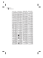
1
PROGRAMMING GUIDE
333 Corporate Woods Parkway
Vernon Hills, Illinois 60061.3109 U.S.A.
Telephone +1 847.634.6700
Facsimile +1 847.913.8766
Zebra Technologies Europe Limited
Zebra House
The Valley Centre, Gordon Road
High Wycombe
Buckinghamshire HP13 6EQ, UK
Telephone +44 (0)1494 472872
Facsimile +44 (0)1494 450103
Customer Order # 46530L
Manufacturer Part # 46530LB
' Zebra Technologies Corporation
Proprietary Statement
This manual contains proprietary information of Zebra Technologies Corporation. It is intended solely for the
information and use of parties operating and maintaining the equipment described herein. Such proprietary
information may not be used, reproduced, or disclosed to any other parties for any other purpose without the
expressed written permission of Zebra Technologies Corporation.
Product Improvements
Continuous improvement of products is a policy of Zebra Technologies Corporation. All specifications and
signs are subject to change without notice.
Liability Disclaimer
Zebra Technologies Corporation takes steps to assure that its published Engineering Specifications and
Manuals are correct; however, errors do occur. Zebra Technologies Corporation reserves the right to correct
any such errors and disclaims liability resulting therefrom.
No Liability for Consequential Damage
In no event shall Zebra Technologies corporation or anyone else involved in the creation, production, or delivery of the accompanying product (including hardware and software) be liable for any damages whatsoever
(including, without limitation, damages for loss of business profits, business interruption, loss of business information, or other pecuniary loss) arising out of the use of or the results of use of or inability to use such
product, even if Zebra Technologies Corporation has been advised of the possibility of such damages. Because some states do not allow the exclusion or limitation of liability for consequential or incidental damages, the above limitation may not apply to you.
Copyrights
This copyrighted manual and the label printers described herein are owned by Zebra Technologies Corporation.
All rights are reserved. Unauthorized reproduction of this manual or the software in the label printer may result
in imprisonment of up to one year and fines of up to $10,000 (17 U.S.C.506). Copyright violators may be subject to civil liability.
IBM® is a registered trademark of IBM Corporation and TrueType® is a registered trademark of Apple Computer. Inc.
Zebra®, Stripe®, ZPL®, and ZPL II® are registered trademarks of Zebra Technologies Corporation.
All other brand names, product names, or trademarks belong to their respective holders.
© Zebra Technologies Corporation, 1998
i
Contents
Chapter 1
Introduction to ZPL II
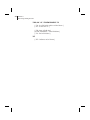
Scope of This Manual . . . . . . . . . . . . . . . . . . . . . . . . . 1
Zebra Programming Language II (ZPL II). . . . . . . . . . . . . . . 1
Why ZPL II and How it Differs from Standard ZPL . . . . . . . . . 1
Working with Examples
. . . . . . . . . . . . . . . . . . . . . . . 3
Chapter 2
ZPL II Basics
More Information About ZPL II . . . . . . . . . . . . . . . . . . . . 5
Format Instructions. . . . . . . . . . . . . . . . . . . . . . . . . . . 7
Control Instructions . . . . . . . . . . . . . . . . . . . . . . . . . . 8
Prefix Rules and Syntax for Control and Format Instructions . . . . . 8
An Example of a Basic Label. . . . . . . . . . . . . . . . . . . . . 10
Zebra Fonts . . . . . . . . . . . . . . . . . . . . . . . . . . . . . . 12
Understanding Bitmapped Font Magnification Factors . . . . . . . . . . . 12
Font Selection . . . . . . . . . . . . . . . . . . . . . . . . . . . . . . . . 12
Proportional Spacing . . . . . . . . . . . . . . . . . . . . . . . . . . . . 13
Bitmap Font Size . . . . . . . . . . . . . . . . . . . . . . . . . . . . . . 13
ii CONTENTS
Differences Between Download Scalable Fonts and Bitmap Fonts. . . . . 14
Downloadable Scalable Fonts . . . . . . . . . . . . . . . . . . . . . . . . 15
Bar Codes . . . . . . . . . . . . . . . . . . . . . . . . . . . . . . . 16
Basic Format for Bar Codes . . . . . . . . . . . . . . . . . . . . . . . . . 16
Bar Code Field Instructions . . . . . . . . . . . . . . . . . . . . . . . . . 17
Further ZPL II Basic Concepts . . . . . . . . . . . . . . . . . . . . 20
Introduction to Device Names . . . . . . . . . . . . . . . . . . . . . . . 20
Introduction to ZPL II Object Names and Extensions . . . . . . . . . . . 21
Using Device and Object Names with ZPL II Instructions. . . . . . . . . . 22
Chapter 3
ZPL II Printer Configuration
Print Mode. . . . . . . . . . . . . . . . . . . . . . . . . . . . . . . . . . 25
Media Tracking . . . . . . . . . . . . . . . . . . . . . . . . . . . . . . . 25
Media Type . . . . . . . . . . . . . . . . . . . . . . . . . . . . . . . . . 26
Media Darkness . . . . . . . . . . . . . . . . . . . . . . . . . . . . . . . 26
Label Top Position . . . . . . . . . . . . . . . . . . . . . . . . . . . . . 27
Set Media Sensors . . . . . . . . . . . . . . . . . . . . . . . . . . . . . . 27
Mode Protection . . . . . . . . . . . . . . . . . . . . . . . . . . . . . . . 27
Reprint After Error . . . . . . . . . . . . . . . . . . . . . . . . . . . . . 27
Configuration Update . . . . . . . . . . . . . . . . . . . . . . . . . . . . 28
Set ZPL . . . . . . . . . . . . . . . . . . . . . . . . . . . . . . . . . . . 28
Setting Up Customized Configuration Formats . . . . . . . . . . . . . . . 28
Chapter 4
ZPL II Programming Exercises
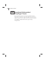
þExercise # 1 - Saving Label Formats as Graphic Images. . . . . . . . .
þExercise # 2 - Downloading and Printing Graphic Images . . . . . . . .
33
36
þExercise # 3 - Printing Quantities of Labels,
Printing Entire Label in Inverted Orientation,
Setting the Print Rate and Suppressing Backfeed . . . . . 40
CONTENTS
þExercise #4 - Slew Instruction, Form Feed Instruction and
Printing Entire Formats in Reverse . . . . . . . . . . . . 43
þExercise # 5 - Using Serialized Fields . . . . . . . . . . . . . . . . . .
48
51
þExercise #7 - Erasing Stored Formats . . . . . . . . . . . . . . . . . . 55
þExercise #8 - Using Variable Data Fields . . . . . . . . . . . . . . . . 58
þExercise #6 - Stored Formats . . . . . . . . . . . . . . . . . . . . . . .
þExercise #9 - Graphic Boxes, Graphic Symbols and
Multiple Elements on One Label . . . . . . . . . . . . . 63
þExercise # 10 - Deleting Graphic Images . . . . . . . . . . . . . . . .
68
Chapter 5
ZPL II Advanced Techniques
Special Effects for Print Fields . . . . . . . . . . . . . . . . . . . . 71
Reverse Printing a Field . . . . . . . . . . . . . . . . . . . . . . . . . . . 71
Reverse Printing a Label . . . . . . . . . . . . . . . . . . . . . . . . . . 71
Printing a Mirror Image . . . . . . . . . . . . . . . . . . . . . . . . . . . 71
Printing a Label Inverted 180 Degrees . . . . . . . . . . . . . . . . . . . 72
Serialized Data . . . . . . . . . . . . . . . . . . . . . . . . . . . . 72
Variable Data . . . . . . . . . . . . . . . . . . . . . . . . . . . . . 72
Stored Formats . . . . . . . . . . . . . . . . . . . . . . . . . . . . 72
Initialize/Erase Stored Formats . . . . . . . . . . . . . . . . . . . . . . . 73
Download Format Instruction . . . . . . . . . . . . . . . . . . . . . . . . 73
Field Number Instruction . . . . . . . . . . . . . . . . . . . . . . . . . . 73
Field Allocate . . . . . . . . . . . . . . . . . . . . . . . . . . . . . . . . 74
Recall Stored Format Instruction . . . . . . . . . . . . . . . . . . . . . . 74
More Examples of Using Stored Format . . . . . . . . . . . . . . . . . . 74
Control Instructions . . . . . . . . . . . . . . . . . . . . . . . . . . 75
Test and Setup Instructions . . . . . . . . . . . . . . . . . . . . . . . . . 75
Calibration and Media Feed Instructions . . . . . . . . . . . . . . . . . . 76
Cancel/Clear Instructions . . . . . . . . . . . . . . . . . . . . . . . . . . 77
Printer Control Instructions . . . . . . . . . . . . . . . . . . . . . . . . . 77
Limitations of Higher Print Speeds . . . . . . . . . . . . . . . . . . . . . 78
iii
iv CONTENTS
Set Dots/Millimeter . . . . . . . . . . . . . . . . . . . . . . . . . . . . . 78
Changing Delimiters and Instruction Prefixes
. . . . . . . . . . . 79
Communication Diagnostics Instructions . . . . . . . . . . . . . . 79
Host Status Instructions. . . . . . . . . . . . . . . . . . . . . . . . 79
Host Identification. . . . . . . . . . . . . . . . . . . . . . . . . . . . . . 79
Print Configuration Label . . . . . . . . . . . . . . . . . . . . . . . . . . 79
Start Print . . . . . . . . . . . . . . . . . . . . . . . . . . . . . . . . . . 80
Networking
. . . . . . . . . . . . . . . . . . . . . . . . . . . . . 80
Assigning Network IDs/Chaining Multiple Printers . . . . . . . . . . . . 80
Connecting Printers into the Network (if they already have network IDs) 81
Graphic Instructions . . . . . . . . . . . . . . . . . . . . . . . . . 82
Boxes and Lines . . . . . . . . . . . . . . . . . . . . . . . . . . . . . . . 82
Working with Hex Graphic Images . . . . . . . . . . . . . . . . . . . . . 82
Alternative Data Compression Scheme for ~DG and ~DB Instructions . . . . 83
Recalling a Hexadecimal Graphic Image . . . . . . . . . . . . . . . . . . 84
Image Move . . . . . . . . . . . . . . . . . . . . . . . . . . . . . . . . . 84
Working with Label Formats as Graphics. . . . . . . . . . . . . . . . . . 84
Reducing Download Time of Graphic Images . . . . . . . . . . . . . . . 85
Transferring Objects Between Storage Devices. . . . . . . . . . . . . . . 86
Deleting Graphics from Memory . . . . . . . . . . . . . . . . . . . . . . 86
Deleting all Graphic Images from DRAM . . . . . . . . . . . . . . . . . 87
Defining and Using the AUTOEXEC.ZPL Function . . . . . . . . . . . . 87
Memory, Flash Cards, Font Cards . . . . . . . . . . . . . . . . . . 88
Memory Status Line . . . . . . . . . . . . . . . . . . . . . . . . . . . . . 89
Shortcuts and Alternate Schemes for Writing ZPL II Scripts
. . . 90
Font Shortcuts . . . . . . . . . . . . . . . . . . . . . . . . . . . . . . . . 92
Command Reference
ZPL II Command Reference
Introduction . . . . . . . . . . . . . . . . . . . . . . . . . . . . . . 95
Using the ZPL II Command Reference . . . . . . . . . . . . . . . . . . . 95
CONTENTS
Appendix A
ZPL II Command Quick Reference Chart
. . . . . . . . . . . . . . . . . . . . . . . . . . . . . . . . . . . . 339
Appendix B
ASCII Code Chart
. . . . . . . . . . . . . . . . . . . . . . . . . . . . . . . . . . . . 345
Appendix C
Mod 10 Check Digit
. . . . . . . . . . . . . . . . . . . . . . . . . . . . . . . . . . . . 347
Appendix D
Mod 43 Check Digit
. . . . . . . . . . . . . . . . . . . . . . . . . . . . . . . . . . . . 349
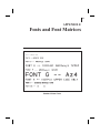
Appendix E
Fonts and Font Matrices
. . . . . . . . . . . . . . . . . . . . . . . . . . . . . . . . . . . . 351
Appendix F
Code Page 850 Chart
. . . . . . . . . . . . . . . . . . . . . . . . . . . . . . . . . . . . 355
Appendix G
Error Detection Protocol
Introduction . . . . . . . . . . . . . . . . . . . . . . . . . . . . . 359
What is a Protocol . . . . . . . . . . . . . . . . . . . . . . . . . . 359
v
vi CONTENTS
How Protocol Works . . . . . . . . . . . . . . . . . . . . . . . . . . . 359
Request Packet Formats (from the Host computer) . . . . . . . . . 360
Response From the Zebra Printer . . . . . . . . . . . . . . . . . . 362
Zebra Packet Response . . . . . . . . . . . . . . . . . . . . . . . . . . 363
Disguising Control Code Characters . . . . . . . . . . . . . . . . 365
Rules for Transactions. . . . . . . . . . . . . . . . . . . . . . . . 366
Error Detection Protocol Application . . . . . . . . . . . . . . . . 366
Activating the Protocol . . . . . . . . . . . . . . . . . . . . . . . . . . 366
Setting Up Communications . . . . . . . . . . . . . . . . . . . . . . . 366
Setting the Printer ID Number . . . . . . . . . . . . . . . . . . . . . . . 366
Error Conditions and System Faults. . . . . . . . . . . . . . . . . 367
Restarting a Transmission . . . . . . . . . . . . . . . . . . . . . . . . . 367
CRC Error Conditions and Responses . . . . . . . . . . . . . . . . . . . 367
Time-Out Error Conditions and Responses . . . . . . . . . . . . . . . . 368
How the Zebra Printer Processes a Request Packet . . . . . . . . . 369
How the Zebra Printer Responds to Host Status . . . . . . . . . . 370
Code for Calculating the CRC for the Zebra Protocol . . . . . . . 371
Glossary
ZPL II and Bar Code Industry Terms
. . . . . . . . . . . . . . . . . . . . . . . . . . . . . . . . . . . . 373
Index
. . . . . . . . . . . . . . . . . . . . . . . . . . . . . . . . . . . . 379
1
CHAPTER 1
Introduction to ZPL II
Scope of This Manual
This manual is a guide to the functions and features of the
Zebra Programming Language II (ZPL II). This manual is effective
for the firmware versions listed below and all firmware versions prior
to these:
14.8.0
Zebra 105S and S500 printers
18.8.0
Zebra 90XiII, 140XiII, 170XiII & 220XiII printers
21.8.0
Zebra 105Se & 160S printers
22.8.6
Zebra Z Series printers
23.8.2
Zebra T300 printers
25.8.2
Zebra A300 printers
26.8.0
Zebra PA400 printers
Zebra Programming Language II (ZPL II)
Zebra Programming Language II (ZPL II) is a high-level label definition and printer control language. Labels may be defined in ZPL II
Language and generated by a host computer system. A commercial
label preparation system or a software package which automatically
generates ZPL II Code may also be used. For information about label
preparation systems, consult your distributor, systems integrator, or
computer software vendor.
Why ZPL II and How it Differs from Standard ZPL
The primary reason for the development of ZPL II was to substantially reduce the time between when a printer begins receiving
label format data and when the first label begins to print. This was
accomplished primarily by changing the way ZPL scripts are written.
®
2 CHAPTER 1
Introduction to ZPL II
NOTE: ZPL II scripts are not 100% compatible with standard
ZPL scripts.
In reality, the differences between ZPL II and Standard ZPL scripts is
minor. Most existing Standard ZPL scripts can be easily modified to
take advantage of ZPL II. You can also write ZPL II scripts that are
compatible with Standard ZPL printers.
There are two major differences between ZPL II and Standard ZPL.
1. With ZPL II, all data fields are formatted as received. In
Standard ZPL, the data fields are not processed until after the
^XZ (End Format) instruction is received.
2. Many new ZPL II commands (instructions) have been added.
In order to take advantage of ZPL II, it is mandatory that when the
following ZPL II instructions are used in a label format, they must
come before the first ^FD (Field Data) command.
^JM, ^LH, ^LL, ^LR, ^LS, ^PM, ^PO, ^PR, and ^PF
NOTE: If these instructions are used in a label format and are not
placed before the first ^FD (Field Data) command, the label may
not print correctly.
NOTE: In the past, ZPL II instructions could only be entered in
upper-case characters. ZPL II instructions can now be entered in
either uppercase characters, lowercase characters, or a combination
of both.
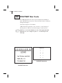
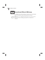
HHIMPORTANTHH
The ZPL II commands listed in this Programming Guide are
available depending on which version of firmware is installed in
your printer and which printer you are using. Please consult the
Command Quick Reference Chart in Appendix A to see which
commands are available for your version of firmware and printer.
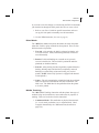
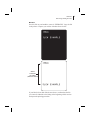
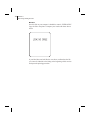
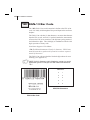
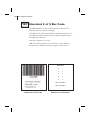
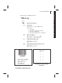
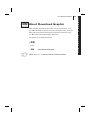
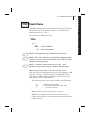
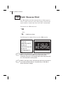
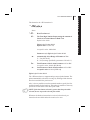
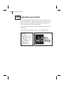
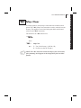
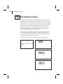
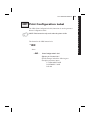
To determine which version of firmware resides in your printer,
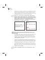
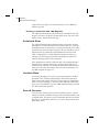
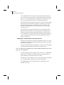
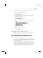
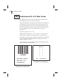
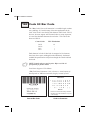
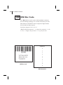
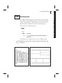
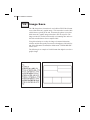
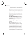
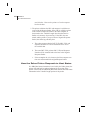
you will need to print out a Printer Configuration Label. Consult
your printer user’s guide for instructions on how to print the
label. The label provides valuable information about your
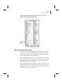
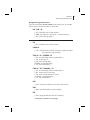
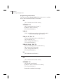
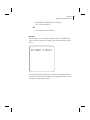
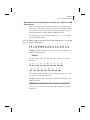
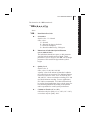
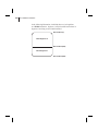
printer’s configuration, memory, options, etc. A sample of the
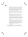
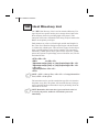
CHAPTER 1
Introduction to ZPL II
Printer Configuration Label is shown below with an arrow
pointing to the firmware information.
FIRMWARE
VERSION
Printer Configuration Label
Working with Examples
Examples are used throughout this guide to assist and instruct both
new and more experienced users. Each example has two parts; the
actual instructions sent to the printer and the results (usually in the
form of a printed label) of those instructions.
It is strongly suggested that new users go through each of the examples, comparing their results with the one shown. Experienced users
may only need to read over the examples, making sure they understand how the results were obtained.
Most of the examples are “stand-alone” and can be completed on an
individual basis. However, some examples assume that a previous
example has already been completed. For instance, an example may
delete a previously saved graphic image.
3
4 CHAPTER 1
Introduction to ZPL II
Before working with the examples, be sure the supplies (ribbon and
media) have been loaded and that the printer has been properly
adjusted for the media (labels). If unfamiliar with these procedures,
refer to the printer user’s guide for assistance.
The examples shown in this guide assume a media size of at least
80mm wide and 60mm long. Media of different sizes can be used,
however parameters affecting size or location of printed data may
need to be modified.
Continuous media can also be used for these examples. Be sure to set
the label length using the ^LL instruction. We recommend using a
label length of 480 dot rows by adding the instruction sequence
^LL480^FS after the ^XA instruction line. Both of these instructions
are covered in detail in the Command Reference section.
The examples are designed for a Zebra printer controlled by a
“stand-alone” (i.e. not part of a network) IBM®-compatible personal
computer. The ZPL II Language uses only printable ASCII characters.
Although a Zebra printer may be controlled by mainframes or minicomputers, we’ve chosen the personal computer as a programming
source because of its relative familiarity among users.
Any word processor or text editor capable of creating ASCII-only
files (files without formatting codes and other extraneous information)
can be used to create the programs in these examples. For instance, if
you are using Microsoft Word®, you would open a Text (.txt) file.
Most of the examples are made up of a series of instruction lines.
When you finish typing a line, press the RETURN or ENTER key.
Then type in the next line. Continue this process for all of the lines in
the example.
NOTE: Factory Default printer settings were used for the examples
in this guide and the printer is set up for tear off operation.
WARNING: The Factory Default for the Darkness (“burn temperature”) setting is set to a low “safe” value at the factory. When
using a printer right out of the box, this value may have to be
changed for proper printing. Refer to the printer user’s guide for
information on how to change this value.
5
CHAPTER 2
ZPL II Basics
ZPL II is Zebra Technologies Corporation’s registered trademark for
its Zebra Programming Language II. ZPL II instructions sent to a
Zebra printer give you the ability to create a wide variety of labels
from the simple to the very complex. The labels can include any combination of text, bar codes, and graphics.
More Information About ZPL II
ZPL II contains a variety of printable character font styles and bar
codes. Various ZPL II instructions let you position print fields anywhere on a label in a horizontal orientation or rotated 90, 180 or 270
degrees clockwise. Graphic images can be read and interpreted provided they are in a binary or “hexadecimal format.” Therefore, if you
can convert a scanned or computer-generated image (i.e. image created using a draw or paint software program) into hexadecimal format,
you can print it on a label. You can use the ZTools™ for Windows program (available from Zebra) to convert the bitmap graphic into the
pure hexadecimal graphic format.
ZPL II instructions consist of a prefix character, a two-character mnemonic code and, where applicable, a parameter string. The entire language is programmable in printable ASCII characters, which allows
easy passage of formats and data through computer networks and protocol converters. ZPL II instructions do not use escape sequences or
control codes. A few instructions do have ASCII control code equivalents, which are noted as they apply.
6 CHAPTER 2
ZPL II Basics
ZPL II is both powerful and flexible, providing all of the following
features:
n Compatibility with PCs, minicomputers, mainframe computers
and networks.
n Serialized label fields, with user-selected starting value and
increment/decrement value.
n Programmable label replicate count, batch quantity control, and
printer pauses that enable batching of labels into usable groups.
n Simple line graphics to eliminate label preprinting.
n Scalable fonts.
n Bitmap image graphics, with library function capability (to store
more than one graphic and recall as needed), for freeform
graphic designs.
You can create and use ZPL II scripts (label formats) one at a time
from any word processor capable of generating an ASCII text file.
You can integrate your Zebra printer into your operations by using
database programs and other languages to generate ZPL II programs.
The ZPL II program is then sent to the Zebra printer through an
appropriate interface (combination of proper cabling, printer configuration, and software settings). The examples in this guide use printable
ASCII characters in all instructions, unless otherwise noted.
There are two types of ZPL II instructions: Format Instructions and
Control Instructions. A discussions of these instructions follows.
CHAPTER 2
ZPL II Basics
Format Instructions
Format instructions are the blueprint of a label. These instructions
define label length, field origin, type of field, field data, and other
information. Format instructions are always preceded by the caret (^)
character. All format instructions are processed in the order received.
Most format instructions are, for the most part, “order-independent.”
For example, instructions to print text at the bottom of a label can
come before the instruction to print a bar code at the top of the same
label.
However, due to the processing method used, some format instructions must be placed before others within the label format. These are:
^LH (Label Home)
^LR (Label Reverse)
^JM (Set Dots/Millimeter)
^PO (Print Orientation)
^LL (Label Length)
^LS (Label Shift)
^PM (Mirror Image)
^PF (Slew Dot Rows)
These commands are explained in detail in the Command Reference
section of this guide.
Multiple label formats are acted on in the order they are received by
the printer.
Format instructions fall into several categories:
n Format bracket instructions
n Label definition instructions
n Field definition instructions
n Field default instructions
n Format default instructions
n Format rotation instructions
n Printer control instructions
n Alphanumeric field instructions
n Bar code field instructions
n Graphic image instructions
7
8 CHAPTER 2
ZPL II Basics
Control Instructions
Control instructions are usually preceded by a tilde (~) character. In
most cases, they cause the printer to take a specific action immediately, such as clearing the memory or feeding a blank label. Control
instructions may interrupt and preempt any format instructions waiting in the printer’s received data buffer.
Prefix Rules and Syntax for
Control and Format Instructions
Format instructions use the caret (^) prefix.
An “RS” (HEX 1E) can be substituted for the (^).
Control instructions use the tilde (~) prefix.
A “DLE” (HEX 10) can be substituted for the (~).
NOTE: Both Format and Control prefix characters can be changed
via ZPL II.
In ZPL II instructions, the caret (^) is treated as an ordinary ASCII
character like any other character you would type in from the
keyboard.
HHIMPORTANTHH
In this manual, when you see the caret (^) character, it indicates
that you are to type the caret (^) character. The caret (^) character is not to be confused with pressing the Control (Ctrl) key on
the keyboard.
The caret (^) is a single printable ASCII character having the code 5E
HEX or 94 decimal. Similarly, the tilde (~) is a single printable ASCII
character having the code 7E HEX or 126 decimal.
A few ZPL II instructions can be sent to the printer as either a Format
Instruction or a Control Instruction. The action performed by the
printer will be the same in either case. These instructions must be preceded by the appropriate prefix (i.e. a ^ or a ~) for the context in
which they are used.
Many ZPL II instructions have parameter strings associated with
them. Changing the value of one or more of these parameters affects
the outcome of the printed label.
CHAPTER 2
ZPL II Basics
If the default value for an instruction parameter suits your application,
you need not specify that parameter. However, parameters are
“position-specific.” If you want to change just the third parameter, for
example, you must indicate that it is the third parameter that you want
to change. To do so, use a comma, the ZPL II delimiter character, to
mark each parameter’s place (i.e. ^AA,,60). If you enter a parameter,
all further parameters to the right are to be defaulted, no further commas are required.
HHIMPORTANTHH
Some instructions include the following abbreviation: {I.V.P. = }
This signifies the Initial Value at Power-up regardless of the value
when the printer was turned off.
NOTE: To permanently save configuration settings in the printer’s
configuration memory, you will need to send a ^JUS command at
the end of the ZPL II script. (See ^JU on page 270)
9
10 CHAPTER 2
ZPL II Basics
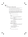
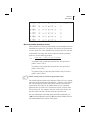
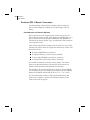
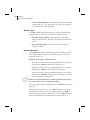
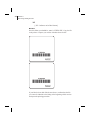
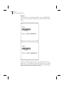
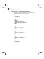
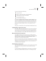
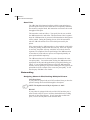
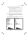
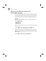
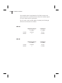
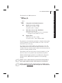
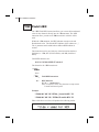
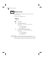
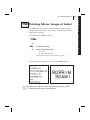
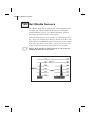
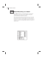
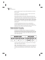
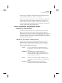
An Example of a Basic Label
This exercise is designed to guide you through the basic steps to create a common label which contains text and a bar code.
Refer to Chapter 4, Introduction, for more information on how to set
up your printer and how to enter ASCII text to send to your printer.
Type the programming instructions (shown in bold) in the order
given. An explanation of what each instruction does is in brackets [ ].
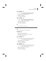
A printed example of the label is on the next page with arrows pointing to the different parts that make up the label and an indication of
the ZPL II command that was used to create it.
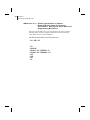
^XA
[^XA - Indicates start of label format.]
^LH30,30
[^LH - Sets label home position 30 dots to the right and
30 dots down from top edge of label.]
^FO20,10^AD^FDZEBRA^FS
[^FO20,10 - Set field origin 20 dots to the right and 10 dots
down from the home position defined by the
^LH instruction.]
[^AD - Select font “D.”]
[^FD - Start of field data.]
[ZEBRA - Actual field data.]
[^FS - End of field data.]
^FO20,60^B3^FDAAA001^FS
[^FO20,60 - Set field origin 20 dots to the right and 60 dots
down from the home position defined by the
^LH instruction.]
[^B3 - Select Code 39 bar code.]
[^FD - Start of field data for the bar code.]
[AAA001 - Actual field data.]
[^FS - End of field data.]
^XZ
[^XZ - Indicates end of label format.]
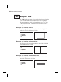
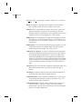
CHAPTER 2
ZPL II Basics
LABEL HOME POSITION (^LH30,30)
(ZEBRA - Actual Field Data)
TEXT
(FONT)
(^AD)
CODE 39
BAR CODE
(^B3)
Y-AXIS
(Dots UP
and
DOWN)
(AAA001 Actual
Field
Data)
X-AXIS
(Dots LEFT and RIGHT)
Basic Label Example with Text and Bar Code
11
12 CHAPTER 2
ZPL II Basics
Zebra Fonts
Most Zebra printers come standard with 8 bitmapped fonts and one
scalable font. Additional downloadable bitmapped and scalable fonts
are also available.
Character size and density (how dark it appears) depends on the density of the printhead and the media used. Three different printheads
are available: 6 dots/mm, 8 dots/mm and 12 dots/mm.
Internal bitmapped fonts can be magnified from 2 to 10 times their
normal (default) size. The magnification factor is in whole numbers.
Therefore, if the normal size of a bit mapped font is 9 dots high and 5
dots wide, a magnification factor of 3 would produce a character of 27
dots high and 15 dots wide. Height and width can be magnified independently.
Understanding Bitmapped Font Magnification Factors
The font instructions in this chapter contain parameters for entering
the height and width of printed characters. The values are always
entered in dots. When entering these values for bitmapped fonts, use
the following formula:
Base Height x Magnification Factor = Height Parameter Value. (Same
principle applies to width.)
EXAMPLE:
Base height of bitmap character is 9 dots.
Base width of bitmap character is 5 dots.
To magnify the character 3 times,
the height parameter is 27
the width parameter is 15.
NOTE: For consistent results, always use the correct parameter
values. See the specific font tables in Appendix C.
Font Selection
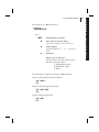
To use a text font, you must either use the change alphanumeric
default font instruction (^CF - explained fully in the Command Reference section, page 180) or specify an alphanumeric field instruction
(^A - explained in the Command Reference section, page 96).
CHAPTER 2
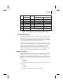
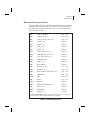
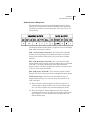
ZPL II Basics
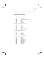
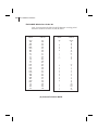
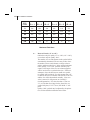
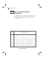
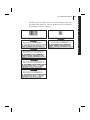
Font
A
B
C,D
E
F
G
H
GS
Ø
Matrix
H×W (in dots)
9x5
11 x 7
18 x 10
28 x 15
26 x 13
60 x 40
21 x 13
24x24
DEFAULT:
15x12
Type*
U-L-D
U
U-L-D
OCR-B
U-L-D
U-L-D
OCR-A
SYMBOL
ICG and Baseline
Intercharacter
Baseline
Gap (in dots)
(in dots)
1
2
2
5
3
8
6
PROPORTIONAL
PROPORTIONAL
7
11
14
23
21
15
21
3 x HEIGHT/4
3 x HEIGHT/4
Table 1. Intercharacter Gap and Baseline Parameters
Proportional Spacing
Proportional spacing is different than fixed spacing. In Table 1, the
Intercharacter Gap (space between characters) is constant for fonts A
thru H. The spacing between all characters is the same. For example,
the spacing between ‘MW’ is the same as between ‘IE.’
The baseline is the imaginary line on which the bottom (base) of all
characters (except any decenders) rest. The area between the baseline
and the bottom of the matrix is used for any character “descenders.”
Baseline numbers given in Table 1 define where the baseline is
located in relationship to the top of the matrix. For example, the baseline for font ‘E’ is 23 dots down from the top of the matrix.
Bitmap Font Size
Alphanumeric field instruction (^A) parameters h and w control the
magnification and therefore, the ultimate size, of the font. The
parameter is specified in dots, but ZPL II actually uses an integer multiplier times the original height/width of the font. For example, if you
specify
^AD,54
you get characters three times their normal size (54 dots high), but if
you specify
^AD,52
you get the same result (not characters 52 dots high).
13
14 CHAPTER 2
ZPL II Basics
Defining only the height or width forces the magnification to be proportional to the parameter defined. If neither is defined, the ^CF
height and width are used. For example, if the height is twice the standard height, the width will be twice the standard width.
NOTE: If a ^CF instruction, with height and width parameters
defined, is used to set the first font, any ^A instructions (to select a
different font) that follow must have the height and width parameter
filled in. If this is not done, the newly selected font will be
magnified using values for the ^CF height and width parameters.
The following is an example of what happens.
Differences Between Download Scalable Fonts and
Bitmap Fonts
For scalable fonts, setting the height and width equally produces the
most balanced looking characters. Balanced characters are very
pleasing to the eye since actual height and width are approximately
equal to each other. This is achieved through the use of a smoothscaling algorithm in the printer.
In the case of a bitmap font this balancing is built into the font. In
actuality, the height of a bitmap font is slightly larger than the width.
Bitmap fonts are always at the maximum size of the characters cell.
The standard Zebra character set is Code 850 for character values
greater than 20 HEX. There are six HEX character values below 20
HEX that are also recognized. The following chart shows how these
character values are printed.
NOTE: Unidentified character values should default to a space.
CHAPTER 2
ZPL II Basics
Downloadable Scalable Fonts
All dot parameters used in the instructions to create Scalable Fonts are
translated into a point size. The printer will convert the dot parameter
to some “point” size, since scalable fonts work in point sizes, not dots.
To determine how many dots must be entered to obtain a particular
point size, use the following formula:
Dots =
( Point Size ) x ( Dots Per Inch of Printer )
72
For printers using a 6 dot/mm print head the “dots per inch of
printer” value is 152.4.
For printers using a 8 dot/mm print head the “dots per inch of
printer” value is 203.
For printers using a 12 dot/mm print head the “dots per inch of
printer” value is 304.8.
NOTE: Actual point size will be an approximate value.
The actual height and width of the character in dots will vary, depending on font style and the particular character. Therefore, some characters will be smaller and some will be larger than the actual dot size
requested.The base lines for all scalable fonts are now calculated
against the dot size of the cell. The base line will be 3/4 down from
the top of the cell. For example, if the size of the cell is 80 dots, the
base line will be 60 dots (3/4) down from the top of the cell.
For more information concerning fonts and related commands, see
~DB (Download Bitmap Font) and ~DS (Download Scalable Font) in
the Command Reference section of this guide.
15
16 CHAPTER 2
ZPL II Basics
Bar Codes
Zebra printers can print the following kinds of bar codes:
ANSI Codabar
CODABLOCK
Data Matrix
Code 11
Code 39
Code 49
Code 93
Code 128 (subsets A, B, and C)
EAN-8
EAN-13
Industrial 2 of 5
Interleaved 2 of 5
LOGMARS
MSI
PDF417
UPS Maxicode
Plessey
PostNet
Standard 2 of 5
UPC-A
UPC-E
UPC/EAN Extensions
Micro-PDF417
QR Code
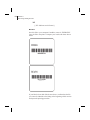
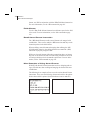
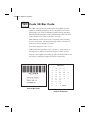
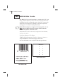
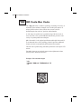
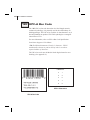
Basic Format for Bar Codes
The basic format for bar codes is: quiet zone, start character, data,
check digit, stop character and quiet zone. Refer to the Sample bar
Code figure below. Not all bar codes require each of these elements.
Every bar code requires a quiet zone. A quiet zone (sometimes called
a “clear area”) is an area adjacent to the machine-readable symbols
that ensure proper reading (decoding) of the symbols. No printing is
permissible within this area. Preprinted characters, borders, and background color are acceptable if they are invisible to the reading device;
these are used in some applications but restricts the type of reading
device that can be used. The size of the quiet zone depends on the size
of bar widths (usually 10 times the width of the narrow bar).
Every bar code contains data made up of a sequence of light spaces
and dark bars that represent letters, numbers, or other graphic
characters. The usable characters differ among the various kinds of
bar codes. Each bar code section in the Command Reference provides
a table of applicable characters. Start and stop characters and check
digits are used by many, but not all, bar codes. These will be indicated
in the specific bar code discussions found in the Command Reference
section.
Sample Bar Code
CHAPTER 2
ZPL II Basics
Bar Code Field Instructions
To create a bar code, a bar code field instruction must be contained in
the label format. Table 2 shows all of the bar code field instructions.
The number in brackets denotes the print ratio. Each instruction produces a unique bar code.
^B1
Code 11 (USD-8)
[ 2.0 - 3.0 ]
^B2
Interleaved 2 of 5
[ 2.0 - 3.0 ]
^B3
Code 39 (USD-3 & 3 of 9)
[ 2.0 - 3.0 ]
^B4
Code 49 (*)
[ Fixed ]
^B7
PDF417 (*)
[ Fixed ]
^B8
EAN-8 (*)
[ Fixed ]
^B9
UPC-E (*)
[ Fixed ]
^BA
Code 93 (USS-93) (*)
[ Fixed ]
^BB
CODABLOCK A, E, F (*)
[ Fixed ]
^BC
Code 128 (USD-6) (*)
[ Fixed ]
^BD
UPS MaxiCode
[ Fixed ]
^BE
EAN-13 (*)
[ Fixed ]
^BF
Micro-PDF417
[ Fixed ]
^BI
Industrial 2 of 5
[ 2.0 - 3.0 ]
^BJ
Standard 2 of 5
[ 2.0 - 3.0 ]
^BK
ANSI Codabar (USD-4 & 2 of 7)
[ 2.0 - 3.0 ]
^BL
LOGMARS
[ 2.0 - 3.0 ]
^BM
MSI
[ 2.0 - 3.0 ]
^BP
Plessey
[ 2.0 - 3.0 ]
^BQ
QR Code
[ Fixed ]
^BS
UPC/EAN Extensions (*)
[ Fixed ]
^BU
UPC-A (*)
[ Fixed ]
^BX
Data Matrix
[ Fixed ]
^BZ
PostNet (*)
[ Fixed ]
(*) Fixed Printing Ratio - This means that the ratio between the width of the
bars in the code is a fixed standard and cannot be changed.
Table 2. Available Bar Codes
17
18 CHAPTER 2
ZPL II Basics
Additionally, each bar code field instruction can be issued with a definition parameter string. The parameter string defines field rotation,
height, and interpretation line status for all bar codes. For some bar
codes, the parameter string also sets a check digit, start character,
and/or stop character. Use the definition parameter string to command
the printer to print bar codes of appropriate heights and densities that
conform to the specifications of the application.
The use of the parameter string is optional since all parameters have
default values. If the default values for all of the bar code parameters
suit the application, then only the bar code instruction needs to be
entered.
Parameters in bar code field instructions are ‘position specific.’ If a
value (other than the default value) is manually entered for one
parameter, a comma “ , ” the ZPL II delimiter character, must be
used to mark the position of the preceding parameters in the string.
To change just the third parameter, enter two commas and then the
value for the third parameter. The default values will be automatically used for the first and second parameters. The following is
an example of how this would actually be entered in the ZPL II
label format.
In our sample label example from Chapter 4, Exercise #9 on page63, a
^B3 bar code field instruction is selected that has five parameters.
The third parameter defines the height of the bar in dots. The bar code
is to be printed using default values for the first two parameters
EXCEPT the height of the bar. This is to be 228 dots. Finally, the
“N” indicates that a print interpretation line will not print with the bar
code. The instruction would be entered as follows:
^B3,,228,N )
NOTE: Delimiters (commas) are not required for parameters
between a manually entered value and the end of the parameter
string.
CHAPTER 2
ZPL II Basics
The bar code instructions are organized into four groups. Each group
represents a particular type of bar code. These groups and the bar
codes they contain are as follows:
NUMERIC-ONLY BAR CODES
^B1
^B2
^BI
^BJ
^BK
^BM
^BP
^BZ
Code 11
Interleaved 2 of 5
Industrial 2 of 5
Standard 2 of 5
ANSI Codabar (or NW-7)
MSI
Plessey
POSTNET
RETAIL LABELING BAR CODES
^B8
^B9
^BE
^BS
^BU
EAN-8
UPC-E
EAN-13
UPC/EAN extensions
UPC-A
ALPHANUMERIC BAR CODES
^B3
^BA
^BC
^BL
Code 39
Code 93
Code 128
LOGMARS
TWO-DIMENSIONAL BAR CODES
^B4
^B7
^BB
^BD
^BF
^BQ
^BX
Code 49
PDF417
CODABLOCK
UPS MaxiCode
Micro-PDF417
QR Code
Data Matrix
19
20 CHAPTER 2
ZPL II Basics
Further ZPL II Basic Concepts
An understanding of the following concepts and terms related to
ZPL II will be helpful in rounding out your knowledge of ZPL II
Basics.
Introduction to Device Names
Device Names have been assigned to the various storage areas for
ZPL II objects (graphic images, label formats, downloaded fonts, etc.)
Device Names are used to identify the DRAM, RAM, EPROM, etc.
This allows for Storage, Recall, Copy, and Deletion of ZPL II Objects
to/from specific areas.
Each of these areas has been assigned a device name as a way of identification. The Device Name is a single letter followed by a colon. The
defined devices are:
n R: Printer DRAM library (read/write)
n B: Optional memory (a card or factory installed)
n E: Extra added EPROM stored objects (read only)
n Z: Internal ZPL II stored object library (read only)
Several ZPL II instructions use these Device Names. The Device
Name is an optional parameter with most ZPL II instructions. Its
default is defined with the individual ZPL II instruction.
The default for the creation and deletion of objects is printer DRAM.
For recalling of objects, the following search priority is used: DRAM,
RAM, extra EPROM, internal ZPL II (R:, B:, E:, Z:, * or ? (All)).
For more information on Device Names and default memory IDs,
please refer to Chapter 5, Advanced Techniques; Memory, Flash
Cards, Font Cards on page 88.
CHAPTER 2
ZPL II Basics
Introduction to ZPL II Object Names and Extensions
Each ZPL II Object (graphic images, label format, etc.) must have a
name. This name will consist of two parts: an Object Name and an
Extension. Object names can be 1 to 8 alphanumeric characters in
length. Extensions consist of a period followed by 3 predefined characters. Object name conventions and extensions are similar to
MS-DOS file name conventions and extensions.
Several ZPL II instructions use these object names. Object names
have no default and must be supplied. Extensions have the defaults
defined below. Depending on the ZPL II instruction, if an extension is
missing, incomplete or incorrect, a default will be used. Defined
extensions for ZPL II Object names, along with their related ZPL II
instructions are:
n .ZPL ZPL II label format (^DF or ^XF)
n .FNT fonts in Zebra format (~DB, ~DS, or ^XA)
n .GRF Zebra bitmap format (~DG, ^IS, ^IL, ^XG or ^IM)
Depending on the ZPL II instruction, the Object name and Extension
may support the use of the asterisk (*) and question mark (?) as wild
cards.
21
22 CHAPTER 2
ZPL II Basics
Using Device and Object Names with ZPL II Instructions
The Device Names and Object Names just described can be used with
ZPL II instructions which support a name parameter. The instructions
are:
n ~DG Download Graphic Image
n ^XG Recall Graphic Image
n ^IS Store format as a graphic image
n ^IL Load Image
n ^IM Move Image
n ^DF Store ZPL II format as text
n ^XF Recall ZPL II format
n ^ID Image Delete
n ^HW Host Directory List
n ^WD Print Directory
n ~DB Download Bitmap
n ~DS Download Scalable Font
The name parameter can consist of either an alphanumeric string of
from 1 to 8 characters, or a string containing a Device Name followed
by an Object Name with an Extension.
Defaults and/or use of the asterisk (*) and question mark (?) as wild
cards will be defined with the individual instruction.
23
CHAPTER 3
ZPL II
Printer Configuration
In most cases, the printer can be configured from either the front panel
or through various ZPL II instructions. Once a configuration instruction is received by the printer, the change will usually affect the
current label format and any future label formats until changed,
the printer is reset, or the printer power is turned off. The next
label printed will reflect the new instruction.
This section discusses how to use the ZPL II printer configuration
instructions. The following is a list of these instructions.
n ^MM (Print Mode) - Sets the printer to one of its four basic
printing modes; Tear-Off, Rewind, Peel-Off and Cutter.
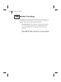
n ^MN (Media Tracking) - Sets the printer for either
Non-Continuous or Continuous media.
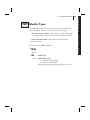
n ^MT (Media Type) - Sets the printer for either Direct Thermal
media or Thermal Transfer media.
n ^MD (Media Darkness) - Adjust how dark the printing will be
by adjusting the “burn temperature” of the printhead.
n ^LT (Label Top) - Shifts printing up to 64 (or ±120 dot rows
based on firmware version) dot rows up or down from the
current Label Home position.
n ^SS (Set Media Sensors) - Allows the user to override all of the
internal values established after running a media profile.
n ^MP (Disable Mode Protection) - Used to disable the front
panel Darkness, Position and Calibrate modes.
n ^JZ (Reprint After Error) - Reprints a label if it was partially or
incorrectly printed due to an error condition.
24 CHAPTER 3
ZPL II Printer Configuration
n ^JU (Configuration Update) - Allows the user to save the
current settings.
n ^SZ (Set ZPL) - Allows the user to select either the ZPL or ZPL
II Programming Language.
Printer configuration instructions must have a parameter in order to be
valid. Instructions with a missing or invalid parameter will be ignored.
For more information regarding these commands and their particular
parameters, please consult the Command Reference section of this
ZPL II Programming Guide.
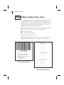
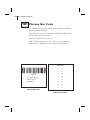
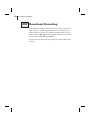
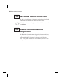
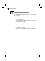
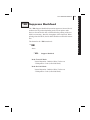
To determine how your printer is currently configured, you can print
out a Printer Configuration Label. Consult your printer user’s guide
for instructions on how to print the label. The label provides valuable
information about your printer’s configuration, memory, options, etc.
A sample of the Printer Configuration Label is shown below.
Once a printer configuration instruction has been issued, it will stay in
effect until the printer is powered down, the printer is reset, or it is
changed by reissuing the instruction with a different set of parameters.
CHAPTER 3
ZPL II Printer Configuration
If you want to save the changes you made using the ZPL II commands
just described or through the front panel, there are two ways to do it.
1. Refer to your User’s Guide for specific instructions on how to
set up your front panel to manually save the instructions.
2. Use the ^JUa instruction. (See note on page 9.)
Print Mode
The ^MM (Print Mode) instruction determines the action the printer
takes after a label or group of labels has been printed. There are four
different modes of operation.
1. Tear Off - After printing, the label is advanced so that the web
is over the tear bar. Label, with backing attached, can then be
torn off manually.
2. Rewind - Label and backing are rewound on an (optional)
internal rewind device. The next label is positioned under the
printhead (no backfeed motion).
3. Peel Off - After printing, the label is partially separated from the
backing. Printing stops until the label is completely removed.
Backing is rewound using an internal backing only rewind
spindle. (NOTE: Select only if printer is equipped with internal
rewind spindle.)
4. Cutter - The web separating the printed label and the next blank
label to be printed is extended into the cutter mechanism. The
label is cut. The blank label is then pulled back into the printer
so it can be printed.
Media Tracking
The ^MN (Media Tracking) instruction tells the printer what type of
media is being used (continuous or non-continuous) for purposes of
tracking. There are two choices for this instruction:
1. Continuous Media - This media has no physical characteristic
(i.e. a web, notch, perforation, etc.) to separate labels. Label
Length is determined by the ^LL instruction (described on
page 278).
25
26 CHAPTER 3
ZPL II Printer Configuration
2. Non-Continuous Media - This media has some type of physical
characteristic (i.e. a web, notch, hole, etc.) that can be detected
by the printer to separate the labels.
Media Type
The ^MT (Media Type) instruction selects the type of media being
used in the printer. There are two choices for this instruction:
1. Thermal Transfer Media - This media uses a high carbon
black or colored ribbon. The ink on the ribbon is bonded to the
media.
2. Direct Thermal Media - The media is heat sensitive and
requires no ribbon.
Media Darkness
The ^MD (Media Darkness) instruction adjusts the darkness relative
to the current darkness setting. The minimum value is -30 and the
maximum value is 30.
Examples for Using the ^MD Instruction
If the current value (value on configuration label) is 16, entering
the instruction ^MD-9 would decrease the value to 7.
If the current value (value on configuration label) is 1, entering
the instruction ^MD15 would increase the value to 16.
If the current value (value on configuration label) is 25, entering
the instruction ^MD10 would only increase the value to 30 since
that is the maximum value allowed.
NOTE: Each ^MD instruction is treated separately with respect to
the current value (value on configuration label).
For example, this is what would happen if two ^MD instructions were
received:
Assume the current value is 15. An ^MD-6 instruction is received
that changes the current value to 9. Another instruction, ^MD2, is
received. The current value is changed 17. The two ^MD instructions
were treated individually with respect to the current value of 15.
CHAPTER 3
ZPL II Printer Configuration
Label Top Position
The ^LT (Label Top) instruction moves the entire label format a
maximum of 64 dot rows up or down from its current position with
respect to the top edge of the label (newer firmware versions allow dot
rows to adjust +120 to -120; see the ^LT command on page 284). A
negative value moves the format towards the top of the label; a positive number moves the format away from the top of the label.
This instruction can be used to fine-tune the position of the finished
label without having to change any of the existing parameters.
NOTE: This instruction does not change the Media Rest position.
Set Media Sensors
The ^SS (Set Media Sensors) instruction is used to change the sensor
values for media, web, ribbon and label length that were set during the
“media calibration” process. (consult the “Media Calibration”
process as described in your printer user’s guide.)
Mode Protection
The ^MP (Mode Protection) instruction is used to disable the various
Mode functions on the front panel. Once disabled, the settings for the
particular mode function can no longer be changed and the LED associated with the function will not light.
Since this instruction has only one parameter, each mode will have to
be disabled with an individual ^MP instruction.
Reprint After Error
The ^JZ (Reprint After Error) instruction is used to reprint a partially
printed label caused by a Ribbon Out, Media Out or Head Open error
condition. The label will be reprinted as soon as the error condition is
corrected.
This instruction will remain active until another ^JZ instruction is
sent to the printer or the printer is turned off.
The ^JZ instruction sets the error mode for the printer. (If ^JZ is
changed, only labels after the change will be affected.)
27
28 CHAPTER 3
ZPL II Printer Configuration
Configuration Update
The ^JU (Configuration Update) instruction sets the active configuration for the printer.
There are three choices for this instruction. They are defined as
follows:
S = Save Current Settings
The current configuration will be saved. This is the configuration
that will be used at Power-On.
F = Reload Factory Values (Default)
The factory values (default values) will be loaded.
(These values will be lost at Power Off if they are not saved with
the ^JUS instruction.)
R = Recall Last Saved Values
The last values saved using this (^JU) instruction or the Mode
Sequencing from the front panel will be loaded.
Set ZPL
The ^SZ (Set ZPL) instruction is used to select the programming language used by the printer. This instruction gives you the ability to
print labels formatted in both ZPL or ZPL II.
This instruction will remain active until another ^SZ instruction is
sent to the printer or the printer is turned off.
Setting Up Customized Configuration Formats
You can save a great deal of time by setting up your own configuration formats. If most of your printing is done on one or two types of
media, you can easily create label formats specifically for those
media.
If you need to print a special label, you change the various instructions and then you only need to change the media and load the new,
specific configuration format.
CHAPTER 3
ZPL II Printer Configuration
Depending on your needs and specific application, the following is a
list of the instructions you might want to put into a configuration format.
^XB
Suppress Backfeed
^PR
Print Rate
^LL
Label Length
^LT
Label Top
^MM
Print Mode
^MT
Media Type
^JZ
Reprint After Error
^SS
Set Media Sensors
^MD
Media Darkness
^MN
Media Tracking
^JU
Configuration Update
^SZ
Set ZPL
NOTE:You can have as many of these format configurations as you
need. Just give them all a different name and send them to the
printer when they are needed.
29
30 CHAPTER 3
ZPL II Printer Configuration
31
CHAPTER 4
ZPL II
Programming Exercises
Introduction
These programming exercises are included to assist and instruct both
the new and more experienced user in the use of various ZPL II
instructions. If you’re a new user, you may find it helpful to complete
all of the exercises. The exercises are simple by design so they can be
completed quickly. More experienced users may want to refer only to
exercises detailing the use of specific instructions or features. Most
exercises are “stand-alone” and can be completed individually. However, some exercises assume that you’ve completed a previous exercise (such as exercises which delete or erase a previously saved
format or graphic image).
Be sure you know how to load supplies and set up the printer before
you begin these exercises. If you haven’t yet learned how to set up
and load supplies into your printer, refer to your user’s guide.
You should ensure that labels of sufficient size (at least 80mm wide
and at least 60mm long for printers with 8 dot/mm print heads) and
(at least 80mm wide and at least 90mm long for printers with 6
dot/mm print heads) have been loaded before starting these exercises.
You can use media of different sizes for these exercises, however you
may need to modify Field Origins (^FO) and other parameters affecting size or location of printed data.
You can also use continuous media for these exercises. If you do, you
must set label length using the ^LL instruction.
These examples are designed for a Zebra printer controlled by
“stand-alone” (i.e. not part of a network) IBM®-compatible personal
32 CHAPTER 4
ZPL II Programming Exercises
computers. The ZPL II Language uses only printable ASCII characters. Although a Zebra printer may be controlled by mainframes or
minicomputers, we’ve chosen the personal computer as a programming source because of its relative familiarity among users.
Any word processor or text editor capable of creating ASCII-only
files (files without formatting codes and other extraneous information)
can be used to create the scripts in these examples. For instance, if
you are using Microsoft Word®, you would open a Text (.txt) file.
Almost all of the examples are made up of a series of lines. When you
finish typing a line, press the RETURN or ENTER key. Then type in
the next line. Continue this process for all of the lines in the example.
NOTE: If the script is in two or more portions, then send the first
portion to the printer and wait to see the result. You can then send
the next potion and any additional scripts, waiting between each to
see the results. Depending on the exercise, the result may be data
uploading to the printer indicated by a flashing (DATA) LED (if
available on your printer) or a sample label will be printed.
NOTE: The actual size of your printed examples may be different
than those shown in the manual. The important thing is that the
information displayed is the same.
NOTE: Factory Default printer settings were used for the examples
in this guide and the printer is set up for tear off operation.
HHIMPORTANTHH
The ZPL II commands listed in this Programming Guide are
available depending on which version of firmware is installed in
your printer and which printer you are using. Please consult the
Command Quick Reference Chart in Appendix A to see which
commands are available for your version of firmware and printer.
To determine which version of firmware resides in your printer,
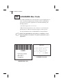
you will need to print out a Printer Configuration Label. Consult
your printer user’s guide for instructions on how to print the
label. The label provides valuable information about your
printer’s configuration, memory, options, etc. A sample of the
Printer Configuration Label is shown in Chapter 1 on page 3 with
an arrow pointing to the firmware information
CHAPTER 4
ZPL II Programming Exercises
þExercise
# 1 - Saving Label Formats as
Graphic Images
This exercise illustrates how to save a label format as a graphic image
in printer RAM and then recall (load) a label format for printing that
has been previously saved. The exercise consists of two scripts. The
first contains a label format and the instructions necessary to save the
format as a graphic image. The second recalls and prints the label format that was saved as the graphic image.
While this exercise utilizes the ^IL instruction to load a graphic
image, the ^IM instruction may also be used. These two instructions
differ in that images loaded using the ^IL instruction are always positioned relative to the ^FO0,0 (Field Origin) command. The ^IM command places the image anywhere on the label as specified by an ^FO
command preceding it.
The ZPL II instructions sent to the printer are:
^XA
^LH30,30
^FO20,10^AFN,56,30^FR^FDZEBRA^FS
^FO20,80^B3N,Y,20,N,N^FDAAA001^FS
^FO10,160^GB150,100,4^FS
^ISR:EXERPROG.GRF,N
^XZ
^XA^ILR:EXERPROG.GRF,N^XZ
33
34 CHAPTER 4
ZPL II Programming Exercises
Programming Instructions
Type the instructions (shown in bold) in the order given. An explanation of what each instruction does is in brackets ( [ ] ).
^XA
[^XA - Indicates start of label format.]
^LH30,30
[^LH - Sets label home position 30 dots to right and 30 dots
down from top edge of label.]
^FO20,10^AFN,56,30^FDZEBRA^FS
[^FO - Set field origin relative to label home.]
[^AF - Select font “F” and sets character size to 56 dots high
and 30 dots wide]
[^FD - Start of field data.]
[ZEBRA- Actual field data.]
[^FS - End of field data.]
^FO20,80,^B3N,Y,20,N,N^FDAAA001^FS
[^FO - Set field origin relative to label home.]
[^B3N,Y,20,N,N - Select Code 39 bar code. Calculate
check digit, do not print interpretation line.]
[^FD - Start of field data for bar code.]
[AAA001 - Actual field data.]
[^FS - End of field data.]
^ISR:EXERPROG.GRF,N
[^IS - Save format as a graphic image named
“EXERPROG.GRF,” do not print after saving.]
^XZ
[^XZ - Indicates end of label format.]
(Data is uploaded to printer RAM.)
^XA^ILR:EXERPROG.GRF,N^XZ
[^XA - Start of label format.]
[^ILR:EXERPROG.GRF,N - Load and print the graphic
image saved as “EXERPROG.GRF”]
[^XZ - End of label format.]
CHAPTER 4
ZPL II Programming Exercises
Review
Save this file on your computer’s harddrive, name it “EXER1.ZPL.”
Copy the file to the printer. Compare your results with those shown
below.
If your label does not look like the one shown, confirm that the file
you created is identical to the listing at the beginning of this exercise
and repeat the printing procedure.
35
36 CHAPTER 4
ZPL II Programming Exercises
þExercise
# 2 - Downloading and Printing
Graphic Images
This exercise illustrates how to create a hexadecimal graphic image
and print it as part of your label.
In order to store graphic images, sufficient memory must be allocated
(reserved) for them. Memory for storing graphic images is allocated
“on the fly” as needed. The graphic images can then be recalled and
integrated with additional label data without downloading the entire
image each time a label is printed. Graphic Images are downloaded
using the ~DG (Download Graphic) instruction along with appropriate parameters to indicate the size of the graphic being downloaded.
Graphic images may be created using a drawing or painting program
which creates files in the .PCX format, such as PC Paintbrush. These
files must then be converted to ZPL II graphic format .GRF (pure
hexadecimal data without headers or other extraneous information) for
use as part of a label format. You can use the ZTools™ for Windows
program (available from Zebra) to convert the .PCX graphic format
into the pure hexadecimal .GRF graphic format. Hexadecimal data
may also be directly input as part of a ZPL II program.
The ~DG instruction requires parameters indicating the size of the
graphic image. The format for this instruction is:
~DGd,o,x,t,w,DATA
where
~DG =
Set Printer to Download Graphic Mode
d=
Destination Device to Store Image
o=
Name of Image, 1-8 Alphanumeric Characters
x=
Extension, 3 Alphanumeric Characters
{Fixed. Will always be .GRF}
t=
Total Number of Bytes in Graphic
w=
DATA =
Number of Bytes Per Row
ASCII Hexadecimal String that Defines Image
CHAPTER 4
ZPL II Programming Exercises
Refer to the ~DG command in the Command Reference section
for detailed instructions on calculating the total number of bytes
and the number of bytes per row.
For this exercise, please create a “smile” graphic in a drawing or paint
program like the one shown below so that the graphic is 1.5 inches x
1.5 inches at 200 dpi.
Save the graphic in .PCX format and name it: SMILE.PCX. Convert
this file to the .GRF format using ZTools™ for Windows.
The ZPL II instructions you will use in this exercise are:
Format Bracket instructions
^XA, ^XZ
Label Field Definition Instructions
^FO, ^FS
Recall Graphic Instruction
^XG
The ZPL II instructions sent to the printer are:
~DGR:SMILE.GRF,12012,39
(depending on the image size and how you created the graphic, there
will be many lines of ASCII HEX data that follow the ~DG instruction
line which is a HEX description of your image)
^XA
^FO50,50^XGR:SMILE.GRF,1,1^FS
^XZ
37
38 CHAPTER 4
ZPL II Programming Exercises
Programming Instructions
Type the instructions (shown in bold) in the order given. An explanation of what each instruction does is in brackets ( [ ] ).
~DGR:SMILE.GRF,12012,39
[^DG - Download graphic named “SMILE,” which has
12012 total bytes with 39 bytes per row]
(depending on the image size and how you created the graphic, there
will be many lines of ASCII HEX data that follow the ~DG instruction
line which is a HEX description of your image)
^XA
[^XA - Indicates start of label format.]
^FO50,50^XGR:SMILE.GRF,1,1^FS
[^FO - Set field origin relative to label home.]
[^XG - Recall graphic named “SMILE” from memory
with a magnification of 1:1 along X and Y axis.]
[^FS - End of field data.]
^XZ
[^XZ - Indicates end of label format.]
CHAPTER 4
ZPL II Programming Exercises
Review
Save this file on your computer’s harddrive, name it “EXER2.ZPL”
Copy the file to the printer. Compare your results with those shown
below.
If your label does not look like the one shown, confirm that the file
you created is identical to the listing at the beginning of this exercise
and repeat the printing procedure.
39
40 CHAPTER 4
ZPL II Programming Exercises
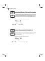
þExercise
# 3 - Printing Quantities of Labels,
Printing Entire Label in Inverted
Orientation, Setting the Print Rate and
Suppressing Backfeed
This exercise illustrates how to set the print speed, print a predetermined quantity of labels, suppress backfeed for tear-off and print
entire labels in an inverted orientation.
The ZPL II instructions sent to the printer are:
^XA^PRB^XZ
^XA
^LH360,30
^FO20,10^AF^FDZEBRA^FS
^FO20,60^B3^FDAAA001^FS
^POI
^PQ2
^XB
^XZ
CHAPTER 4
ZPL II Programming Exercises
Programming Instructions
Type the instructions (shown in bold) in the order given. An explanation of what each instruction does is in brackets.
^XA^PRB^XZ
[^XA - Indicates start of label format.]
[^PRB - Set print rate to speed “B.” (3 inches/second)]
[^XZ - End of ZPL program.]
^XA
[^XA - Indicates start of label format.]
^LH360,30
[^LH - Sets label home position 360 dots to right and 30 dots
down from top edge of label.]
^FO20,10^AF^FDZEBRA^FS
[^FO - Set field origin relative to label home.]
[^AF - Select font “F”
[^FD - Start of field data.]
[ZEBRA- Actual field data.]
[^FS - End of field data.]
^FO20,20,^B3^FDAAA001^FS
[^FO - Set field origin relative to label home.]
[^B3 - Select Code 39 bar code.]
[^FD - Start of field data for bar code.]
[AAA001 - Actual field data.]
[^FS - End of field data.]
^POI
[^POI - Set print orientation to Invert the entire label.]
^PQ2
[^PQ2 - Set print quantity to print 2 labels.]
^XB
[^XB - Suppress Backfeed for tear-off modes.]
Instructions continued on next page.
41
42 CHAPTER 4
ZPL II Programming Exercises
^XZ
[^XZ - Indicates end of label format.]
Review
Save this fileon your harddrive, name it “EXER3.ZPL” Copy the file
to the printer. Compare your results with those shown below.
If your labels do not look like the ones shown, confirm that the file
you created is identical to the listing at the beginning of this exercise
and repeat the printing procedure.
CHAPTER 4
ZPL II Programming Exercises
þExercise
#4 - Slew Instruction,
Form Feed Instruction and
Printing Entire Formats in Reverse
This exercise illustrates the slew and form feed (slew to home)
instructions and the instructions required for printing the entire label
in reverse.
The ZPL II instructions sent to the printer are:
^XA
^PR2
^LRY
^LH30,30
^FO0,0^GB400,300,300^FS
^FO20,10^AF^FDZEBRA^FS
^FO20,60^B3,,40^FDAAA001^FS
^PF50
^FO20,160^AF^FDSLEW EXAMPLE^FS
^XZ
^XA^PH^XZ
^XA
^PR2,6
^FO20,10^AF^FDZEBRA^FS
^FO20,60^B3,,40^FDAAA001^FS
^PF250
^FO20,160^AF^FDSLEW EXAMPLE^FS
^XZ
43
44 CHAPTER 4
ZPL II Programming Exercises
Programming Instructions
Type the instructions (shown in bold) in the order given. An explanation of what each instruction does is in brackets.
^XA
[^XA - Indicates start of label format.]
^PR2
[^PR2 - Set print rate to speed of 2 inches/second]
^LRY
[^LRY - Reverse print entire label.]
^LH30,30
[^LH - Sets label home position 30 dots to right and 30
dots down from top edge of label.]
^FO0,0^GB400,300,300^FS
[^FO - Set field origin relative to label home.]
[^GB - Create a filled graphic box to be used as
background for reverse printed label. (May need
to adjust parameters for different media size.]
^FO20,10^AF^FDZEBRA^FS
[^FO - Set field origin relative to label home. ]
[^AF - Select font “F.”]
[^FD - Start of field data.]
[ZEBRA- Actual field data.]
[^FS - End of field data.]
^FO20,60^B3,,40^FDAAA001^FS
[^FO - Set field origin relative to label home.]
[^B3 - Select Code 39 bar code.]
[^FD - Start of field data for bar code.]
[AAA001 - Actual field data.]
[^FS - End of field data.]
^PF50
[Slew 50 dot rows at bottom of label.]
CHAPTER 4
ZPL II Programming Exercises
^FO20,160^AF^FDSLEW EXAMPLE^FS
[^FO - Set field origin relative to label home. ]
[^AF - Select font “F.”]
[^FD - Start of field data.]
[SLEW EXAMPLE - Actual field data.]
[^FS - End of field data.]
^XZ
[^XZ - Indicates end of format.]
^XA^PH^XZ
[Instructions to feed to next home position.]
^XA
[^XA - Indicates start of format.]
^PR2,6
[^PR2 - Set print rate to speed of 2 inches/second, set slew
rate to speed of 6 inches/second]
^FO20,10^AF^FDZEBRA^FS
[^FO - Set field origin relative to label home. ]
[^AF - Select font “F.”]
[^FD - Start of field data.]
[ZEBRA- Actual field data.]
[^FS - End of field data.]
^FO20,60^B3,,40^FDAAA001^FS
[^FO - Set field origin relative to label home.]
[^B3 - Select Code 39 bar code.]
[^FD - Start of field data for bar code.]
[AAA001 - Actual field data.]
[^FS - End of field data.]
^PF250
[^PF250 - Slew 250 dot rows.]
Instructions continued on next page.
45
46 CHAPTER 4
ZPL II Programming Exercises
^FO20,160^AF^FDSLEW EXAMPLE^FS
[^FO - Set field origin relative to label home. ]
[^AF - Select font “F.”]
[^FD - Start of field data.]
[SLEW EXAMPLE - Actual field data.]
[^FS - End of field data.]
^XZ
[^XZ - Indicates end of format.]
CHAPTER 4
ZPL II Programming Exercises
Review
Save this file on your harddrive, name it “EXER4.ZPL” Copy the file
to the printer. Compare your results with those shown below.
SLEW
PORTION
OF LABEL
(250 DOT ROWS)
If your labels do not look like the ones shown, confirm that the file
you created is identical to the listing at the beginning of this exercise
and repeat the printing procedure.
47
48 CHAPTER 4
ZPL II Programming Exercises
þExercise
# 5 - Using Serialized Fields
This exercise discusses the instructions and parameters required to
produce serialized fields as part of a label format.
The ZPL II instructions sent to the printer are:
^XA
^LH30,30
^FO20,10^AF^FDZEBRA^FS
^FO20,60^B3,,40,,^FDAA001^FS
^FO20,180^AF^SNSERIAL NUMBER 00000000111,1,Y^FS
^PQ10
^XZ
CHAPTER 4
ZPL II Programming Exercises
Programming Instructions
Type the instructions (shown in bold) in the order given. An explanation of what each instruction does is in brackets.
^XA
[^XA - Indicates start of label format.]
^LH30,30
[^LH - Sets label home position 30 dots to right and 30
dots down from top edge of label.]
^FO20,10^AF^FDZEBRA^FS
[^FO - Set field origin relative to label home. ]
[^AF - Select font “F.”]
[^FD - Start of field data.]
[ZEBRA- Actual field data.]
[^FS - End of field data.]
^FO20,60^B3,,40,,^FDAA001^FS
[^FO - Set field origin relative to label home.]
[^B3 - Select Code 39 bar code.]
[^FD - Start of field data for bar code.]
[AA001 - Actual field data.]
[^FS - End of field data.]
^FO20,180^AF^SNSERIAL NUMBER 00000000111,1,Y^FS
[^FO - Set field origin relative to label home. ]
[^AF^SNSERIAL NUMBER 00000000111,1,Y- Define
serialized field, starting value of 111, increment
by 1, insert leading zeros.]
[^FS - End of field data.]
^PQ10
[^PQ10 - Set print quantity to 10.]
^XZ
[^XZ- Indicates end of format.]
49
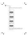
50 CHAPTER 4
ZPL II Programming Exercises
Review
Save this file to your computer’s harddrive, name it “EXER5.ZPL”
Copy the file to the printer. Compare your results with those shown
below.
A total of 10 labels should be printed. The first and last labels are
shown here. If your labels do not look like the ones shown, confirm
that the file you created is identical to the listing at the beginning of
this exercise and repeat the printing procedure.
CHAPTER 4
ZPL II Programming Exercises
þExercise
#6 -
Stored Formats
This exercise illustrates the instructions and parameters required to
use stored formats.
The ZPL II instructions sent to the printer are:
^XA
^DFFORMAT^FS
^LH30,30
^FO20,10^AF^FN1^FS
^FO20,60^B3,,40,,^FN2^FS
^XZ
^XA
^XFFORMAT
^FN1^FDZEBRA^FS
^FN2^FDAAA001^FS
^XZ
^XA
^XFFORMAT
^FN1^FDBEARS^FS
^FN2^FDZZZ999^FS
^XZ
51
52 CHAPTER 4
ZPL II Programming Exercises
Programming Instructions
Type the instructions (shown in bold) in the order given. An explanation of what each instruction does is in brackets.
^XA
[^XA - Indicates start of label format.]
^DFFORMAT^FS
[^DF - Download and store format.]
[FORMAT - Name of format.]
[^FS - End of field data.]
^LH30,30
[^LH - Sets label home position 30 dots to right and 30
dots down from top edge of label.]
^FO20,10^AF^FN1^FS
[^FO - Set field origin relative to label home. ]
[^AF - Select font “F.”]
[^FN1 - Assign field number 1.]
[^FS - End of field data.]
^FO20,60^B3,,40,,^FN2^FS
[^FO - Set field origin relative to label home.]
[^B3 - Select Code 39 bar code.]
[^FN2 - Assign field number 2.]
[^FS - End of field data.]
^XZ
[^XZ- Indicates end of format.]
^XA
[^XA - Indicates start of label format.]
^XFFORMAT^FS
[^XF - Recall stored format.]
[FORMAT - Name of format to be recalled.]
[^FS - End of field data.]
Instructions continued on next page.
CHAPTER 4
ZPL II Programming Exercises
^FN1^FDZEBRA^FS
[^FN1 - Indicate following data should be inserted
in area allocated for field number 1.]
[^FD - Indicate start of field data.]
[ZEBRA - Field data.]
[^FS - End of field data.]
^FN2^FDAAA001^FS
[^FN2 - Indicate following data should be inserted
in area allocated for field number 2.]
[^FD - Indicates start of field data.]
[AAA001 - Field data.]
[^FS - End of field data.]
^XZ
[^XZ- Indicates end of format.]
^XA
[^XA - Indicates start of label format.]
^XFFORMAT^FS
[^XF - Recall stored format.]
[FORMAT - Name of format to be recalled.]
[^FS - End of field data.]
^FN1^FDBEARS^FS
[^FN1 - Indicates following data should be inserted
in area allocated for field number 1.]
[^FD - Indicates start of field data.]
[BEARS - Field data.]
[^FS - End of field data.]
^FN2^FDZZZ999^FS
[^FN2 - Indicates following data should be inserted
in area allocated for field number 2.]
[^FD - Indicates start of field data.]
[ZZZ999 - Field data.]
[^FS - End of field data.]
53
54 CHAPTER 4
ZPL II Programming Exercises
^XZ
[^XZ- Indicates end of format.]
Review
Save this file to your computer’s harddrive, name it “EXER6.ZPL”
Copy the file to the printer. Compare your results with those shown
below.
If your labels do not look like the ones shown, confirm that the file
you created is identical to the listing at the beginning of this exercise
and repeat the printing procedure.
CHAPTER 4
ZPL II Programming Exercises
þExercise
#7 -
Erasing Stored Formats
This exercise illustrates the instructions required to erase any stored
formats saved in the printer memory.
The ZPL II instructions sent to the printer are:
^XA
^EF^FS
^XZ
^XA
^XFFORMAT
^FN1^FDBEARS^FS
^FN2^FDZZZ999^FS
^FO30,30^CFF^FDNO FORMAT TO RECALL^FS
^XZ
55
56 CHAPTER 4
ZPL II Programming Exercises
Programming Instructions
Type the instructions (shown in bold) in the order given. An explanation of what each instruction does is in brackets.
^XA
[^XA - Indicates start of label format.]
^EF^FS
[^EF - Erase all previously stored formats.]
[^FS - End of field data.]
^XZ
[^XZ- Indicates end of format.]
^XFFORMAT^FS
[^XF - Recall stored format.]
[FORMAT - Name of format to be recalled.]
[^FS - End of field data.]
^FN1^FDBEARS^FS
[^FN1 - Indicates following data should be inserted
in area allocated for field number 1.]
[^FD - Indicates start of field data.]
[BEARS - Field data.]
[^FS - End of field data.]
^FN2^FDZZZ999^FS
[^FN2 - Indicates following data should be inserted
in area allocated for field number 2.]
[^FD - Indicates start of field data.]
[ZZZ999 - Field data.]
[^FS - End of field data.]
^FO30,30^CFF^FDNO FORMAT TO RECALL^FS
[^FO30,30 - Set field origin relative to label home.]
[^CFF - Change to font “F”.]
[^FD - Indicates start of field data.]
Instructions continued on next page.
CHAPTER 4
ZPL II Programming Exercises
[NO FORMAT TO RECALL - Field data.]
[^FS - End of field data.]
^XZ
[^XZ- Indicates end of format.]
Review
Save this file to your computer’s harddrive, name it “EXER7.ZPL”
Copy the file to the printer. Compare your results with those shown
below.
If your label does not look like the one shown, confirm that the file
you created is identical to the listing at the beginning of this exercise
and repeat the printing procedure.
57
58 CHAPTER 4
ZPL II Programming Exercises
þExercise
#8 -
Using Variable Data Fields
This exercise illustrates the instructions and parameters required to
produce serialized fields as part of a label format.
The ZPL II instructions sent to the printer are:
^XA^MCY^XZ
^XA
^LH30,30
^FO20,10^AF^FVZEBRA^FS
^FO20,60^B3N,,100^FDAAA001^FS
^MCN
^XZ
^XA
^FO20,10^AF^FVCUBS^FS
^XZ
^XA
^FO20,10^AF^FVBULLS^FS
^XZ
^XA
^FO20,10^AF^FVBEARS^FS
^XZ
^XA^MCY^XZ
CHAPTER 4
ZPL II Programming Exercises
Programming Instructions
Type the instructions (shown in bold) in the order given. An explanation of what each instruction does is in brackets.
^XA^MCY^XZ
[^XA - Indicates start of label format.]
[^MCY - Map Clear ]
[^XZ - End of format.]
^XA
[^XA - Indicates start of label format.]
^LH30,30
[^LH - Sets label home position 30 dots to right and 30
dots down from top edge of label.]
^FO20,10^AF^FVZEBRA^FS
[^FO - Set field origin relative to label home. ]
[^AF - Select font “F.”]
[^FV - Indicates start of VARIABLE field data.]
[ZEBRA - Variable data.]
[^FS - End of field data. ]
^FO20,60^B3N,,100^FDAAA001^FS
[^FO - Set field origin relative to label home.]
[^B3 - Select Code 39 bar code.]
[^FD - Start of field data for bar code.]
[AAA001 - Actual field data.]
[^FS - End of field data.]
^MCN
[^MCN - Set Map Clear to N=No.]
^XZ
[^XZ - End of format.]
59
60 CHAPTER 4
ZPL II Programming Exercises
^XA
[^XA - Indicates start of label format.]
^FO20,10^AF^FVCUBS^FS
[^FO - Set field origin relative to label home. ]
[^AF - Select font “F.”]
[^FV - Indicates start of VARIABLE field data.]
[CUBS- Variable data.]
[^FS - End of field data.]
^XZ
[^XZ - End of format.]
^XA
[^XA - Indicates start of label format.]
^FO20,10^AF^FVBULLS^FS
[^FO - Set field origin relative to label home. ]
[^AF - Select font “F.”]
[^FV - Indicates start of VARIABLE field data.]
[BULLS - Variable data.]
[^FS - End of field data.]
^XZ
[^XZ - End of format.]
^XA
[^XA - Indicates start of label format.]
^FO20,10^AF^FVBEARS^FS
[^FO - Set field origin relative to label home. ]
[^AF - Select font “F.”]
[^FV - Indicates start of VARIABLE field data.]
[BEARS - Variable data.]
[^FS - End of field data.]
Instructions continued on next page.
CHAPTER 4
ZPL II Programming Exercises
^XZ
[^XZ - End of format.]
^XA^MCY^XZ
[^XA - Indicates start of label format.]
[^MCY - Map Clear ]
[^XZ - End of format.]
61
62 CHAPTER 4
ZPL II Programming Exercises
Review
Save this file to your computer’s harddrive, name it “EXER8.ZPL”
Copy the file to the printer. Compare your results with those shown
below.
A total of 4 labels should be printed. They are shown here. If your
labels do not look like the one shown, confirm that the file you created
is identical to the listing at the beginning of this exercise and repeat
the printing procedure.
CHAPTER 4
ZPL II Programming Exercises
þExercise
#9 -
Graphic Boxes, Graphic Symbols and
Multiple Elements on One Label
This exercise illustrates the instructions and parameters required to
produce a label which, when combined with elements from the previous exercises, will incorporate multiple graphic and text elements
such as a graphic box, line, graphic symbol, bar code and a hexadecimal bitmapped graphic.
NOTE: For the sake of this label example, all dimensional or
directional unit references are represented in DOTS. See the ^MU
(Mode Units) command on page 296 for more information on
setting units of measurement.
The ZPL II instructions sent to the printer are:
^XA
^LH0,0
^LL992
^FO147,639^BY3,3.0^B3N,,228,N^FDSMILE^FS
^FO120,108^A0N,89^FDA Guide to^FS
^FO120,207^A0N,89^FDZPL II^FS
^FO120,306^A0N,89^FDProgramming^FS
^FO120,405^A0N,89^FDLanguage^FS
^FO696,149^A0R,71,66^FR^SN123456,1,Y^FS
^FO683,135^FR^GB0,216,108^FS
^FO591,636^XGSMILE.GRF,1,1^FS
^FO377,216^GSN,55,40^FDA^FS
^FO75,63^GB769,856,10^FS
^FO113,559^GB703,0,9^FS
^PQ1
^PR6
^XZ
63
64 CHAPTER 4
ZPL II Programming Exercises
Programming Instructions
Type the instructions (shown in bold) in the order given. An explanation of what each instruction does is in brackets ( [ ] ).
^XA
[^XA - Indicates start of label format.]
^LH0,0
[^LH - Sets label home position at the upper left corner of
the label.]
^LL992
[^LL - Sets label length to 992 dots rows along the Y-axis.]
^FO147,639^BY3,3.0^B3N,,228,N^FDSMILE^FS
[^FO - Set field origin relative to label home.]
[^BY - Set Bar Code Field Default values to 3 dots for
narrow bar width and wide bar to narrow bar
width ratio to 3.0 units.]
[^B3N,,228,N - Select Code 39 bar code. Do not calculate
check digit, set bar code height to 228 dots,
do not print interpretation line.]
[^FD - Start of field data for bar code.]
[SMILE- Actual field data.]
[^FS - End of field data.]
^FO120,108^A0N,89^FDA Guide to^FS
[^FO - Set field origin relative to label home.]
[^A0 - Select default font “0”, normal orientation,
character height of 89 dots, standard width.]
[^FD - Start of field data.]
[A Guide to - Actual field data.]
[^FS - End of field data.]
^FO120,207^A0N,89^FDZPL II^FS
[^FO - Set field origin relative to label home.]
[^A0 - Select default font “0”, normal orientation,
character height of 89 dots, standard width.]
[^FD - Start of field data.]
[ZPL II - Actual field data.]
[^FS - End of field data.]
CHAPTER 4
ZPL II Programming Exercises
^FO120,306^A0N,89^FDProgramming^FS
[^FO - Set field origin relative to label home.]
[^A0 - Select default font “0”, normal orientation,
character height of 89 dots, standard width.]
[^FD - Start of field data.]
[Programming - Actual field data.]
[^FS - End of field data.]
^FO120,405^A0N,89^FDLanguage^FS
[^FO - Set field origin relative to label home.]
[^A0 - Select default font “0”, normal orientation,
character height of 89 dots, standard width.]
[^FD - Start of field data.]
[Language - Actual field data.]
[^FS - End of field data.]
^FO696,149^A0R,71,66^FR^SN123456,1,Y^FS
[^FO - Set field origin relative to label home.]
[^A0R - Select default font “0”, rotated 90 degrees
clockwise, character height of 71 dots,
character width of 66 dots.]
[^FR - Set field to be reverse print as white letters.]
[^SN123456,1,Y- Define serialized field, starting value of
123456, increment by 1, insert leading zeros.]
[^FS - End of field data.]
^FO683,135^FR^GB0,216,108^FS
[^FO - Set field origin relative to label home.]
[^FR - Set field (box for serial numbers) to be reverse print
as black.]
[^GB0,216,108 - Set graphic box to be width of 0, height of
216 dots, 108 dots thick (same as specifying width).]
[^FS - End of field data.]
^FO591,636^XGR:SMILE.GRF,1,1^FS
[^FO - Set field origin relative to label home.]
[^XGSMILE.GRF,1,1 - Recall SMILE.GRF graphic from
printer memory, magnification factor of 1 on the
X-axis and 1 on the Y-axis.]
[^FS - End of field data.]
65
66 CHAPTER 4
ZPL II Programming Exercises
^FO377,216^GSN,55,40^FDA^FS
[^FO - Set field origin relative to label home.]
[^GSN,55,40 - Set graphic symbol with normal orientation
to be height of 55 dots, width of 40 dots.]
[^FDA - Select field data of registered trademark character.]
[^FS - End of field data.]
^FO75,63^GB769,856,10^FS
[^FO - Set field origin relative to label home.]
[^GB769,856,10 - Set graphic box (large box around
perimeter of label) to be width of 769 dots,
height of 856 dots and 10 dots thick.]
[^FS - End of field data.]
^FO113,559^GB703,0,9^FS
[^FO - Set field origin relative to label home.]
[^GB703,0,9 - Set graphic line (horizontal line near middle
of label) to be width of 703 dots,
height of 0 dots and 9 dots thick.]
[^FS - End of field data.]
^PQ1
[^PQ1 - Set print quantity of 1 label.]
^PR6
[^PR6 - Set print rate at 6 inches per second.]
^XZ
[^XZ - Indicates end of label format.]
CHAPTER 4
ZPL II Programming Exercises
Review
Save this file on your computer’s harddrive, name it “EXER9.ZPL”
Copy the file to the printer. Compare your results with those shown
below.
If your label does not look like the one shown, confirm that the file
you created is identical to the listing at the beginning of this exercise
and repeat the printing procedure.
67
68 CHAPTER 4
ZPL II Programming Exercises
þExercise
# 10 - Deleting Graphic Images
This exercise illustrates how to delete a graphic image previously
stored in printer memory. Graphic images may be deleted from printer
memory using either the ^ID instruction which is used to delete a specific graphic image stored in memory or the ^EG (Erase Download
Graphics) instruction which erases ALL graphic images stored in
memory.
NOTE: A ~EG instruction sent to the printer will also delete ALL
images stored in memory.
This exercise will erase the graphic image named “SMILE.GRF”
which was previously stored in Exercise #2 and used in Exercise #9.
The ZPL II instructions sent to the printer are:
^XA
^IDR:SMILE.GRF
^XZ
^XA
^FO50,50^XGR:SMILE.GRF
^FO50,90^AF^FDLOOK, NO SMILE^FS
^XZ
CHAPTER 4
ZPL II Programming Exercises
Programming Instructions
Type the instructions (shown in bold) in the order given. An explanation of what each instruction does is in brackets.
^XA
[^XA - Indicates start of label format.]
^IDR:SMILE.GRF
[^ID - Delete the image called SMILE from memory.]
^XZ
[^XZ - Indicates end of label format.]
^XA
[^XA - Indicates start of label format.]
^FO50,50^XGR:SMILE.GRF
[This line attempts to call the graphic image that was
just deleted. If the deletion was successful, only the
following line will print.]
^FO50,90^AF^FDLOOK, NO SMILE^FS
[^FO - Set field origin relative to label home.
[^AF - Select font “F.”]
[^FD - Start of field data.]
[LOOK, NO SMILE - Actual field data.]
[^FS - End of field data.]
^XZ
[^XZ - Indicates end of label format.]
69
70 CHAPTER 4
ZPL II Programming Exercises
Review
Save this file on your computer’s harddrive, name it “EXER10.ZPL”
Copy the file to the printer. Compare your results with those shown
below.
If your label does not look like the one shown, confirm that the file
you created is identical to the listing at the beginning of this exercise
and repeat the printing procedure.
71
CHAPTER 5
ZPL II
Advanced Techniques
This chapter presents information and instructions for using more
advanced techniques such as special effects, serialized data fields,
control instructions, program delimiters, communications, and memory cards.
Special Effects for Print Fields
ZPL II includes a few “Special Effects” instructions which are outlined below.
Reverse Printing a Field
The ^FR (Field Reverse Print) instruction allows a field to appear as
white over black or black over white. When printing a field, if the dot
would normally print black, it is made white; if the dot would normally be white, it is made black. For more information, see the ^FR
command on page 222.
Reverse Printing a Label
The ^LR (Label Reverse Print) instruction reverses the printing of all
fields in the label format. It allows a field to appear as white over
black or black over white. When printing a field, if the dot would normally print black, it is made white; if the dot would normally be
white, it is made black. For more information, see the ^LR command
on page 280.
Printing a Mirror Image
The ^PM (Print Mirror Image of Label) instruction prints the entire
printable area of the label as a mirror image. This instruction flips the
72 CHAPTER 5
ZPL II Advanced Techniques
image from left to right. For more information, see the ^PM command on page 301.
Printing a Label Inverted 180 Degrees
The ^PO (Print Orientation) instruction inverts the label format 180
degrees. In essence, the label is printed upside down. For more information, see the ^PO command on page .
Serialized Data
The ^SN (Serialization Data) instruction allows the printer to index
data fields by a selected increment or decrement value (i.e., make the
data fields increase or decrease by a specified value) each time a label
is printed. This can be performed on up to 100 to 150 fields in a given
format and can be performed on both alphanumeric and bar code
fields. A maximum of 12 of the right-most integers are subject to
indexing. The first integer found when scanning from right to left
starts the indexing portion of the data field.
If the alphanumeric field to be indexed ends with an alpha character,
the data will be scanned, character-by-character, from right to left
until a numeric character is encountered. Serialization will take place
using the value of the first number found. For more information, see
the ^SN command on page 314.
Variable Data
To increase throughput, you can set up a program that uses variable
data fields. Then, instead of formatting the whole label each time a
label is printed, the printer will have to format only the changed data
field. To use this capability, you must use the ^MC and ^FV instructions. For more information, see the ^MC command on page 285 and
the ^FV command on page 226.
Stored Formats
You can create formats and save them in volatile memory. A stored
format can then be recalled and merged with downloaded data to form
a complete label. This process saves transmission time but not formatting time. It is particularly useful if you are not working with an intelligent input device.
CHAPTER 5
ZPL II Advanced Techniques
To create a format do the following:
n Design the label.
n Replace variable data fields with field numbers.
n Allocate space for the size of the field.
n Give the format a name.
n Save the format to the printer.
You can store multiple formats, limited by available DRAM. If you
try to save a format that would overload memory, that format is not
stored. You DO NOT receive an error message that the format is not
stored. You will learn that the format was not stored only when you
try to recall it (and are unable to do so) or if you print the List of
Formats.
If the power is turned OFF, ALL stored formats in DRAM will be lost.
Initialize/Erase Stored Formats
The ^EF or ~EF (Erase Format) instruction erases all stored formats.
If you use the erase format instruction, you erase all stored formats.
(Stored formats can be selectively erased using the ^ID instruction.)
For more information, see the ^EF or ~EF commands on page 212.
Download Format Instruction
The ^DF (Download Format) instruction saves the ZPL II format
instructions as text strings to be later merged using ^XF with variable
data. The format to be stored may contain Field Number (^FN)
instructions to be referenced when recalled.
While use of stored formats will reduce transmission time, no formatting time is saved since this instruction saves the ZPL II as text strings
which need to be formatted at print time. For more information, see
the ^DF command on page 200
Field Number Instruction
The ^FN (Field Number) instruction is used to number the data fields.
This instruction is used in both Store Format and Recall Format
operations.
In a stored format, the ^FN instruction is used where you would normally use the ^FD (Field Data) instruction. In recalling the stored
73
74 CHAPTER 5
ZPL II Advanced Techniques
format, use ^FN in conjunction with the ^FD (Field Data) instruction.
For more information, see the ^FN command on page 219.
Field Allocate
Use the ^FA (Field Allocate) instruction to allocate space for the field
to be saved. For more information, see the ^FA command on page
213.
Recall Stored Format Instruction
The ^XF (Recall Format) recalls a stored format to be merged with
variable data. There can be multiple ^XF instructions and they can be
located anywhere in the label format.
When recalling a stored format and merging data utilizing the ^FN
(Field Number) function, the calling format must contain the (^FN)
instruction to properly merge the data.
While use of stored formats will reduce transmission time, no formatting time is saved since the ZPL II format being recalled was saved as
text strings which need to be formatted at print time. For more information, see the ^XF command on page 334.
More Examples of Using Stored Format
Working with Stored Format instructions involves designing and saving a stored format, then recalling and merging the format with some
variable data.
The following is an example of how to use the various Stored Format
instructions. First, enter the following format and send it to the printer.
Notice that no label is printed. (DATA Indicator went On and Off.)
CHAPTER 5
ZPL II Advanced Techniques
Second, enter the following format and send it to the printer. The label
shown will be printed.
Control Instructions
Control instructions may be sent from the host at any time to elicit an
immediate response from the printer. Control instructions may be sent
in a group or singly.
A control instruction causes the printer to take direct software action
(such as clearing the memory), physical action (such as moving to
next home position), or a combination (such as feeding a label and
calculating and storing its length).
The basic format for using all of the control instructions is:
~(2 letter instruction)
Test and Setup Instructions
The following instructions, presented in alphabetical order, are used to
test various elements of the printer and its status.
Sending the ~HM (Memory Status) instruction to the printer, immediately returns a memory status message to host. Use this instruction
whenever you need to know the status of the memory.
Sending the ~HS (Host Status) instruction to the printer, immediately
returns a three-line printer status message to the host. Use this instruction whenever you need to know the status of the printer.
The ~JR (Power On Reset) instruction resets all of the printer’s internal software, performs a power-on self-test, clears the buffer and
DRAM, and resets communication parameters and default values.
~JR performs the same function as a manual power-on reset.
75
76 CHAPTER 5
ZPL II Advanced Techniques
The ~JN (Head Test Fatal) instruction resets the printhead element
error override, acting as a toggle for ~JO. Printer then goes into fault
status (i.e., turns head indicator on steadily) if any subsequent execution of the printing element test detects bad printing elements.
The ~JO (Head Test Non-Fatal) instruction overrides a failure of head
element status check and allows printing to continue. The override is
canceled when the printer is turned off or receives a ~JR or ~JN
instruction. The printhead test will not produce an error if the ~JO
override is active.
The ^JT (Head Test Interval) instruction lets you change the printhead test interval from 100 to any desired interval. The printer automatically performs an internal printhead element test which occurs
every 100 labels. This takes place during formatting which minimizes
a delay in printing. Therefore, the test may be performed while the
printer is in PAUSE.
Calibration and Media Feed Instructions
The following instructions, presented in alphabetical order, are used to
perform various media and ribbon calibrations and also set the media
feed mode for the printer.
The ~JC (Set Media Sensor Calibration) is used to force a label length
measurement and recalibrate the media and ribbon sensors.
NOTE: In continuous mode, only the media and ribbon sensors will
be recalibrated.
The ~JG (Graphing Sensor Calibration) is used to force a label length
measurement, recalibrate the media and ribbon sensors and print a
graph (media sensor profile) of the sensor values.
The ~JL (Set Label Length) is used to set the label length. Depending
on size of label, printer will feed one or more blank labels.
The ^MF (Media Feed) instruction dictates what happens to the
media at “power up.”
CHAPTER 5
ZPL II Advanced Techniques
Cancel/Clear Instructions
The following instructions control the contents of the Zebra input
buffer:
The ~JA (Cancel All) instruction cancels all format instructions in the
buffer. It also cancels any batches that may be printing.
The printer will stop printing after the current label (if one is printing)
is finished printing. All internal buffers will be cleared of data. The
“DATA” LED will turn off.
Printer Control Instructions
The following instructions control various printer operations.
The ~PH or ^PH (Slew to Home Position) instruction causes the
printer to feed one blank label.
The ~PH instruction feeds one label after the format currently being
printing is done or when the printer is placed in pause.
The ^PH instruction feeds one blank label after the format it is in
prints.
The ~PP (Programmable Pause) instruction stops printing after the
current label is printed (if one is printing) and places the printer in the
Pause mode.
The ^PP (Programmable Pause) is not immediate. Therefore, several
labels may be printed before a pause is performed. This instruction
will pause the printer after the format it is in prints.
The operation is identical to pressing the PAUSE button on the front
panel of the printer. The printer will remain paused until the PAUSE
button is pressed or a ~PS instruction is sent to the printer.
The ~PS (Print Start) instruction causes a printer in the Pause mode to
resume printing. The operation is identical to pressing the PAUSE
button on the front panel of the printer when the printer is already in
the Pause mode.
The ^PF (Slew Given Number of Dot Rows) instruction causes the
printer to slew labels (move labels at a high speed without printing) a
specified number of dot rows, at the bottom of the label. This allows
faster printing when the bottom portion of a label is blank.
77
78 CHAPTER 5
ZPL II Advanced Techniques
The ^PQ (Print Quantity) instruction gives control over several
printing operations. It controls the number of labels to print, the
number of labels printed before printer pauses, and the number of replications of each serial number.
The ^PR (Print Rate) instruction determines the media speed
during printing and the slew speed (feeding a blank label).
The printer will operate with the selected speeds until the setting is
resent in a subsequent format or the printer is turned off.
The print speed is application specific. Since print quality is affected
by media and ribbon, printing speeds and printer operating modes, it
is very important to run tests for your applications.
Limitations of Higher Print Speeds
n Use thermal transfer mode only.
n Horizontal bar codes with a minimum X dimension of 5 mil may
be printed at print speeds of 2" (51mm) per second.
n Rotated bar codes are limited to a minimum x dimension of
10mil (modulus 2) at higher print speeds. At x dimension of 5
mil (modulus 1), they may be printed at 2" per second.
n Font A at a magnification of 1 is not recommended; all other
fonts are acceptable.
Set Dots/Millimeter
Use the ^JM (Set Dots/Millimeter) instruction to change the number
of dots per millimeter. Depending on the print head, normal dots per
millimeter on a Zebra Printer is 12-dots/mm (304-dots/inch),
8-dots/mm (203-dots/inch) or 6-dots/mm (153-dots/inch). In some
applications, this high density is not required. For these applications, a
lower density of 4-dots/mm (102-dots/inch) or 3-dots/mm (77dots/inch) can be selected. For more information, see the ^JM command on page 263.
If used, this instruction must be entered before the first ^FS
instruction.
CHAPTER 5
ZPL II Advanced Techniques
Changing Delimiters and Instruction Prefixes
For some applications, you may need to change the ZPL II delimiter
(default “,”) the format instruction prefix (default: “^”), and/or the
control instruction prefix (default: “~”). You can change these characters to any ASCII characters you choose, using the appropriate
instructions.
You might do this if you are using a hand-held terminal that does not
have a comma to enter the ZPL II instructions, if you are working
with a mainframe that has trouble processing the caret, or if you find
some other character(s) easier to use.
Communication Diagnostics Instructions
Zebra printers support communication diagnostics through both hardware and software control. You can use these diagnostics to troubleshoot programs.
The ~JD (Enable Communications Diagnostics) instruction initiates a
diagnostic mode that produces an ASCII printout (using current label
length and full width of printer) of all characters received by the
printer. This printout includes the ASCII Characters, the HEX value
and any communication errors.
The ~JE (Disable Diagnostics) instruction cancels the diagnostic
mode and returns the printer to normal label printing.
Host Status Instructions
Host Identification
The ~HI (Host Identification) instruction is designed to be sent from
the Host to the Zebra printer to find out the type of Zebra printer.
Upon receipt, the Zebra printer will respond to the Host with a character string that gives information about the printer such as the version
of firmware, dots per inch, memeory and printer options.
Print Configuration Label
The ~WC (Print Configuration Label) instruction is used to generate a
Printer Configuration Label.
NOTE: This instruction only works when the printer is idle.
79
80 CHAPTER 5
ZPL II Advanced Techniques
Start Print
The ^SP (Start Print) instruction allows a label to start printing at a
specified point before the entire label has been completely formatted.
On extremely complex labels, this instruction can increase the overall
throughput of the print.
The instruction works as follows. You specify the dot row at which
the ^SP instruction is to take affect. This then creates a label ‘segment.’
Once the ^SP instruction is processed, all information in that segment
will be printed. During the printing process, all of the instructions
after the ^SP will continue to be received and processed by the
printer.
If the segment after the ^SP instruction (or the remainder of the label)
is ready for printing, media motion does not stop. If the next segment
is not ready, the printer will stop “mid-label” and wait for the next
segment to be completed. Precise positioning of the ^SP instruction
is somewhat of a trial-and-error process as it depends primarily on
print speed and label complexity.
The ^SP instruction can be effectively used to determine the worst
case print quality. You can determine if using the ^SP instruction is
appropriate for the particular application by using the following procedure. If you send the label format up to the first ^SP instruction
and then wait for printing to stop before sending the next segment, the
printed label will be a sample of the worst case print quality. It will
also drop any field that is out of order.
Networking
Assigning Network IDs/Chaining Multiple Printers
LCD Front Panel
If your printer is equiped with an LCD Front Panel, then you have the
option of setting the network ID through the front panel.
NOTE: The default network ID for all printers is “000”.
RS-232C
If your printer is equipped with only one RS-232C interface port, it
must be used as the last printer in a daisy-chained Selective Calling
Network of other Zebra printers. If your printer has two RS-232C
ports, it can be used anywhere in the network chain.
CHAPTER 5
ZPL II Advanced Techniques
If your printer is not equipped with an LCD Front Panel, use the following steps to assign network IDs and chain multiple printers within
an RS-232C network:
1. Send a ~NR command - to make sure all printers are in
transparent mode. (See ~NR on page 299)
2. Send a ~NC000 command - this connects to the first printer in
the chain that has an ID of 000. (See ~NC on page 297)
3. Send a ^NIXXX command - this is where XXX is the new
ID for the printer. (See ^NI on page 298) Issue a ^JUS
command to save current settings. (See ^JU on page 270)
4. Send a ~NT command - this allows you to prepare to initialize
the next printer in the chain. (See ~NT on page 299)
5. Repeat steps 2 through 4 until all printers are initialized.
RS-485 (use these steps if there is no LCD Front Panel)
If you want to set up an RS-485 network, you will need to initialize
with a one printer network configuration for each printer using the following steps:
1. Send a ^NIXXX command - this is where XXX is the new
ID for the printer. (See ^NI on page 298)
2. Issue a ^JUS command to save current settings.
(See ^JU on page 270)
Connecting Printers into the Network (if they already
have network IDs)
Use the ~NC (Network Connect) command to connect a particular
printer into the network by calling up the printer’s Network ID Number. You can then send data to the printer. You can then use the ~NT
command to disconnect (set transparent) the printer if desired when
data transmission has finished.
81
82 CHAPTER 5
ZPL II Advanced Techniques
Graphic Instructions
In addition to text and bar codes, three types of graphics can be
printed on a Zebra printer:
n Boxes and lines.
n ZPL II label formats saved as graphic images.
n Graphic images in Hexadecimal format.
ZPL II has a format instruction that will create boxes and lines as part
of any label format. These label formats can also be stored as graphic
images and data can be merged with them at print time. Additionally,
ZPL II will permit the printing of graphic images from other sources
that have been created in (or converted to) hexadecimal (HEX) format. Such graphic images can come from a variety of sources, including CAD programs, draw and paint programs, and scanned images.
Boxes and Lines
The ^GB (Graphic Box) instruction is used to draw boxes and/or lines
as part of a label format. Boxes and lines can be use to highlight
important information, divide labels into distinct areas, or just dress
up the way the label looks.
Working with Hex Graphic Images
ZPL II can be used to save graphic images in HEX format in DRAM,
FLASH, PCMCIA, or battery backed up SRAM, depending on the
type of memory installed in your printer. The image might be created
using a CAD program, a draw or paint program, or a scanner. These
images can then be printed on the label. Graphic images may be created using a program which creates files in the .PCX format. These
files must then be converted to ZPL II graphic format .GRF (pure
hexadecimal data without headers or other extraneous information) for
use as part of a label format. You can use the ZTools™ for Windows
program (available from Zebra) to convert the .PCX graphic format
into the pure hexadecimal .GRF graphic format. Hexadecimal data
may also be directly input as part of a ZPL II program. Manually preparing a string of HEX code is possible but usually impractical.
CHAPTER 5
ZPL II Advanced Techniques
Alternative Data Compression Scheme for ~DG and ~DB
Instructions
There is an alternative data compression scheme recognized by the
Zebra printer. This scheme further reduces the actual number of data
bytes and the amount of time required to download graphic images
and bitmapped fonts with the ~DG and ~DB instructions.
The following represent the repeat counts 1,2,3,4,5,....,19 on a subsequent Hexadecimal value.
NOTE: Values start with G since 0 thru 9 and A thru F are already
used for HEX values.)
G H I JK LMN O P Q R S T U V W X Y
1 2 3 4 5 6 7 8 9 10 11 12 13 14 15 16 17 18 19
Example: Sending a M6 to the printer is identical to sending the following Hexadecimal data:
6666666
The “M” has the value of 7. Therefore “M6" sends seven (7) hexadecimal 6’s.
g h i j
k
l
m n
o
p q
20 40 60 80 100 120 140 160 180 200 220
r
s
t
u
v
w
x
y
z
240 260 280 300 320 340 360 380 400
The numbers above represent the repeat counts 20, 40, 60, 80,....400
on a subsequent Hexadecimal value.
Example: Sending a hB to the printer is identical to sending the following HEX data:
BBBBBBBBBBBBBBBBBBBBBBBBBBBBBBBBBBBBBBBB
The “h” has the value of 40. Therefore “hB” sends forty (40) hexadecimal B’s.
83
84 CHAPTER 5
ZPL II Advanced Techniques
Repeat Values
Several repeat values can be used together to achieve any value desired.
“vMB” or “MvB” will send 327 hexadecimal B’s to the printer.
a comma (,) fills the line, to the right, with zeros (0) until the
specified line byte is filled.
an exclamation mark (!) fills the line, to the right, with ones (1)
until the specified line byte is filled.
a colon (:) denotes repetition of the previous line.
Recalling a Hexadecimal Graphic Image
The ^XG (Recall Graphic) instruction is used to recall one or more
graphic images for printing. This instruction is used in a label format
to merge pictures such as company logos and piece parts, with text
data to form a complete label.
An image may be recalled and resized as many times per format as
needed. Other images and data may be added to the format.
Image Move
The ^IM (Image Move) instruction performs a direct move of an
image from storage area into the bitmap. The instruction is identical
to the Recall Graphic instruction except that there are no sizing
parameters.
Working with Label Formats as Graphics
The ^IS (Image Save) and ^IL (Image Load) instructions are used to
save a ZPL label format (including text and/or bar codes) in the
printer’s DRAM, FLASH, PCMCIA, or battery backed up SRAM, as
a special graphic image. This lets you increase the throughput of a
series of similar but not identical labels.
Instead of formatting each individual label completely, store the constant fields as an image (i.e create a template). Then, in subsequent
label formats, instructions are issued to recall that graphic image format and merge it with variable data.
CHAPTER 5
ZPL II Advanced Techniques
Reducing Download Time of Graphic Images
There is a method of reducing the actual number of data bytes sent to
the printer when using the ~DG instruction. This is shown in Figures
4.1 and 4.2 along with the graphic.
In Figure 4.2, if the HEX string ends in an even number of zeros (0’s),
a single comma (,) can be substituted for ALL of the zeros. If the
HEX string ends in an odd number of zeros, one zero and a single
comma is required. The exclamation mark (!) and the colon (:)
described under ‘Repeat Values’ on the previous page can also be
used.
NOTE: The text rows in your editor may not be the same as the dot
rows used by ZPL II. The editor may word wrap or truncate the dot
rows. ZPL II ignores the end of a text line (ie. carriage returns and
line feed characters).
NOTE: In Figures 4.1 and 4.2, carriage returns have been inserted
at the end of every dot row for visual clarity.
~DGTRAINGLE,42,6,
FO0000000000
FF0000000000
FFF000000000
FFFFF0000000
FFFFFF000000
^XA
^FO50,50
^XGTRIANGLE,1,1^FS
^FO100,100
^XGTRIANGLE,10,10^FS
^XZ
Figure 4.1 Complete Graphic
Coding
~DGTRIANGLE,42,6,
FO,
FF,
FFF0,
FFFFF0,
FFFFFF,
^XA
^FO50,50
^XGTRIANGLE,1,1^FS
^FO100,100
^XGTRIANGLE,10,10^FS
^XZ
Figure 4.2 Condensed Graphic
85
86 CHAPTER 5
ZPL II Advanced Techniques
Transferring Objects Between Storage Devices
The ^TO (Transfer Object) instruction is used to copy an object or
group of objects from one storage device to another. It is quite similar
to the copy function used in PC’s.
Source and destination devices must be supplied and must be different and valid for the action specified. Invalid parameters will
cause the instruction to be ignored.
There are no defaults associated with this instruction. However, the
asterisk (*) may be used as a wild card for Object names and extensions. For instance, ZEBRA.* or *.GRF would be acceptable forms
for use with ^TO instruction.
The Asterisk (*) can be used to transfer multiple object files (except
*.FNT) from the DRAM to the Memory Card. For example, you have
several object files that contain logos. These files are named
LOGO1.GRF, LOGO2.GRF, and LOGO3.GRF.
For example...
You want to transfer all of these files to the Memory Card using the
name NEW instead of LOGO. By placing an Asterisk (*) after both
LOGO and NEW in the transfer instruction, you can copy all of these
files with one instruction. The format for this would be as follows.
^XA
^TOR:LOGO*.GRF,B:NEW*.GRF
^XZ
NOTE: If, during a multiple transfer, a file is to big to be stored on
the Memory Card, it will be skipped. All remaining files will be
checked to see if they can be stored. Those that can be stored, will be
stored.
Deleting Graphics from Memory
The ^ID (Item Delete) instruction deletes objects, images, fonts,
formats etc. from storage areas selectively or in groups. This instruction can be used within a printing format to delete objects just prior to
saving new ones or can be in a stand-alone type format simply to
delete objects.
The object name and extension support the use of the asterisk (*) as a
wildcard. This allows for easy deletion of selected groups of objects.
CHAPTER 5
ZPL II Advanced Techniques
The following are various examples of using the ^ID instruction.
To delete just stored formats from DRAM:
^XA^IDR:*.ZPL^XZ
To delete formats and images named SAMPLE from DRAM
regardless of the extension:
^XA^IDR:SAMPLE.*^XZ
To delete the image SAMPLE1.GRF prior to storing SAMPLE2.GRF:
^XA
^FO25,25^AD,18,10^FDDelete^FS
^FO25,45^AD,18,10^FDthen Save^FS
^IDR:SAMPLE1.GRF^FS
^ISR:SAMPLE2.GRF^FS
^XZ
To delete everything from DRAM:
^XA^IDR:*.*^XZ
Deleting all Graphic Images from DRAM
The ~EG or ^EG (Erase Downloaded Graphics) instruction is used to
delete all graphic images (label format images and hexadecimal
images) from DRAM.
Defining and Using the AUTOEXEC.ZPL Function
An AUTOEXEC.ZPL file function is supported by the printer. It
functions in much the same way as the autoexec.bat file in MS-DOS.
It can be used for setting up various parameters at the time the printer
is powered up (i.e. ^COY, ^LL, ^CWf, etc.). It can also be recalled
at any time after power up.
This file must initially be in the extra EPROM, FLASH or PCMCIA
memory. When the printer is powered on, it looks to the extra memory site for the stored format called AUTOEXEC.ZPL. If found, the
contents of the file are automatically executed as a stored format.
87
88 CHAPTER 5
ZPL II Advanced Techniques
Memory, Flash Cards, Font Cards
Zebra printers come with a variety of memory options. These include
DRAM, EPROM, PCMCIA, FLASH, SOCKET FLASH and
BATTERY BACKED-UP RAM. Depending on which printer model
you have, on most Zebra printers you can print out a Printer Configuration Label which will show the letter designation(s) assigned to your
printer memory. Some printer models do not support this feature,
however, so the following chart should help you in determining how
the memory IDs are assigned (memory IDs default to these values
when the printer is reset to factory defaults):
EPROM
PCMCIA
FLASH
DRAM
BATTERY BACKED-UP RAM
SOCKET FLASH
E:
B:
E:
R:
B: or E:
B:
NOTE: Not all memory options are available on all printers
There are a few ZPL II commands that directly affect the types of
memory available to Zebra printers. They are ~JB, ^JB and ~HM.
The ~JB (Reset Battery Dead) instruction is used for the following two
conditions.
1. This instruction must be sent to the printer if the battery
supplying power to the Battery Powered Font Card fails and is
replaced. (A bad battery would show a “battery dead” condition
on the Printer Configuration Label.)
NOTE: If the battery is replaced and this instruction is not sent to
the printer, the Battery Powered Font Card will not function.
2. To intentionally clear (reinitialize) the Battery Powered
Font Card.
The ^JB (Initialize Flash Memory) instruction is used to initialize the
two types of Flash Memory available in the Zebra printers.
CHAPTER 5
ZPL II Advanced Techniques
NOTE: This command is only available in certain Zebra printers
and based on the firmware installed in the printer. Please consult
the Command Quick Reference Chart (Appendix A) for a complete
listing of firmware that supports ^JB.
Sending the ~HM (Host Memory Status) instruction to the printer
immediately returns a memory status message to the host. Use this
instruction whenever you need to know the status of the memory.
When the Host Memory Status Command, ~HM, is sent to the Zebra
printer, a line of data containing three numbers is sent back to the
Host. The information contained in that line is described here.
Memory Status Line
1024,0780,0780
The first value is the total amount of RAM (Random Access Memory) installed in the printer. This number is in Kilobytes.
The second value is the maximum amount of RAM (Random Access
Memory) available to the user. This number is in Kilobytes.
The third value is the amount of RAM (Random Access Memory)
currently available to the user. This number is in Kilobytes.
89
90 CHAPTER 5
ZPL II Advanced Techniques
Shortcuts and Alternate Schemes for
Writing ZPL II Scripts
ZPL II programming scripts can be written in a variety of ways. There
are, however, more efficient ways to write a ZPL II script depending
on the application and the commands used. The following are certain
ways to write the same ZPL II script, each yeilding the same result.
Example 1:
The Code 39 bar code (^B3) example shown on page 104 shows the
ZPL II script written as:
^XA^FO100,75^BY3
^B3N,N,100,Y,N
^FD123ABC^XZ
Since it is only one field, however, the entire command can be written
as a one line entry:
^XA^FO100,75^BY3^B3N,N,100,Y,N^FD123ABC^XZ
Finally, this script can be further simplified by writing it on one line,
using the comma (,) delimeter to reduce the default parameters in the
^B3 command and eliminating the default parameters at the end of the
^B3 command:
^XA^FO100,75^BY3^B3,,100^FD123ABC^XZ
CHAPTER 5
ZPL II Advanced Techniques
Example 2:
You may prefer to write your ZPL II scripts in any way that makes
sense to you. Some programmers prefer to write out each format
instruction and field on a line by line basis like this:
^XA
^PR2^FS
^LL935^FS
^LH30,30^FS
^FO20,10^AF^FDZEBRA^FS
^FO20,60^B3,,40^FDAA001^FS
^FO20,180^AF^SNSERIAL NUMBER 00000000111,1,Y^FS
^PQ10^FS
^XZ
Although this script will print with no problems, it contains unnecessary ^FS (Field Separator) commands which have been placed after
the format commands. Some programmers feel it is required to place a
^FS command at the end of each line, but the ^FS command is only
needed to separate specific fields. Therefore, the script would transmit
more quickly written like this:
^XA
^PR2
^LL935
^LH30,30
^FO20,10^AF^FDZEBRA^FS
^FO20,60^B3,,40^FDAA001^FS
^FO20,180^AF^SNSERIAL NUMBER 00000000111,1,Y^FS
^PQ10
^XZ
Other programmers prefer to keep the format instructions on one line
as an organizational preference, like this:
^XA^PR2^LL935^LH30,30
^FO20,10^AF^FDZEBRA^FS
^FO20,60^B3,,40^FDAA001^FS
^FO20,180^AF^SNSERIAL NUMBER 00000000111,1,Y^FS
^PQ10^XZ
The label will print out the same so you should develop a scripting
pattern that suits your own organizational style but one which is efficient and is concerned with keeping transmission times to a minimum.
91
92 CHAPTER 5
ZPL II Advanced Techniques
Font Shortcuts
There are times when you might include a specific font into your
script and use it repeatedly within different fields. The following is an
example of one way to write this script:
^XA
^FO120,108^A0N,89^FDA Guide to^FS
^FO120,207^A0N,89^FDZPL II^FS
^FO120,306^A0N,89^FDProgramming^FS
^FO120,405^A0N,89^FDLanguage^FS
^XZ
Notice that the ^FS command is used on the second to last line to
close the field. Actually, it is unnecessary because the ^XZ will
accomplish the same thing, so we can remove it from our script. Also,
since the font and font size are not changing within the fields, this
script can be simplified for quicker transmission by removing the
unnecessary font entries and listing the font information once using
the ^CF command (see ^CF command on page 180):
^XA
^CF0,89
^FO120,108^FDA Guide to^FS
^FO120,207^FDZPL II^FS
^FO120,306^FDProgramming^FS
^FO120,405^FDLanguage
^XZ
This script can be made even more efficient by including the ^FB
command to identify the left origin of the text which occurs at the
same place each time(see ^FB command on page 214):
^XA
^CF0,89
^FO120,108
^FB300,4
^FDA Guide to\&ZPL II\&Programming\&Language
^XZ
NOTE: The entries “\&” within the text indicate a carriage
return/line feed as allowed by the ^FB command. For more
information, see the ^FB comand on page 214.
CHAPTER 5
ZPL II Advanced Techniques
If you wanted to change the font type or size within the script, however, you would need to include the specific font parameters within
the field where the change occurs. In this case, you would not want to
use the ^FB command because the change in font size (in our example below) will affect the y-axis (up and down) position of the text.
You can still use the ^CF command, but you will need to include the
specific font information on the line where the change in the field
occurs:
^XA
^CF0,89
^FO120,108^FDA Guide to^FS
^FO120,207^FDZPL II^FS
^FO120,306^A0N,110^FDProgramming^FS
^FO120,426^FDLanguage
^XZ
93
94 CHAPTER 5
ZPL II Advanced Techniques
95
ZPL II
Command Reference
Introduction
The ZPL II Command Reference, a comprehensive guide to ZPL II
commands, lists all commands in alphabetical order. This listing
includes the commands originally introduced with ZPL II as well as
newly introduced parameters for those commands. Some entirely new
ZPL II commands have been added due to the introduction of new
printer firmware and also for specific applications. Please refer to the
Command Quick Reference Chart (Appendix A) for a complete listing
of the ZLP II commands detailing in which version of firmware the
command was introduced.
Using the ZPL II Command Reference
For a novice or experienced user, the best way to learn the details of
ZPL II is to familiarize yourself with a the concepts in Chapters 1-5
and then you can learn more about a specific command by using the
Command Reference.The command descriptions in this reference
assume you have already read Chapters 1-5. The graphics and examples that accompany the commands should give you a good idea of the
command in a typical application. If no example is given, the command’s use is simple enough to not require an example.
HHIMPORTANTHH
Some instructions include the following abbreviation: {I.V.P. = }
This signifies the Initial Value at Power-up regardless of the value
when the printer was turned off.
C
O
M
M
A
N
D
R
E
F
E
R
E
N
C
E
96 ZPL II COMMAND REFERENCE
^A
Scalable/Bitmapped Font
The ^A (Scalable/Bitmapped Font) instruction is used with the builtin fonts or TrueType® fonts. Scalable fonts (also known as smooth
vector fonts) expand the character size horizontally, vertically or in
both dimensions on a dot by dot basis. Bitmapped fonts are made up
of pixel elements and are slightly taller than their width. Bitmapped
fonts are always at the maximum size of the characters cell.
The built-in scalable font (AØ = CG Triumvirate Bold Condensed®)
defaults to no rotation, a character height of 15 dots and a character
width of 12 dots. The printer will attempt to print a scalable font based
upon the rotation, height in dots and width in dots parameters used
with the ^A instruction.
Example of Scalable Font Instruction
Example of Bitmapped Font Instruction
ZPL II COMMAND REFERENCE
The format for the ^A instruction is
^Af,o,h,w
where
^A =
Scalable/Bitmapped Font
f=
Desired Font
Default value: Ø (CG Triumvirate Bold Condensed®)
Other values: A thru Z, and 1-9.
(Any font in the printer including downloaded fonts,
EPROM stored fonts and fonts A-Z and 1-9 can be
selected via ^CW.)
Instruction ignored if value is incorrect or not specified.
o=
Font Orientation
Default value: ^FW default or last ^FW value.
Other values:
N = Normal
R = Rotated, 90 degrees clockwise;
I = Inverted, 180 degrees
B = Read from Bottom up, 270 degrees.
h=
Character Height in Dots
Scalable:
Default value: 15 dots or last ^CF value.
Acceptable values: 10 - 1500 dots
Bitmapped:
Default value: Standard matrix height for specified
bitmapped font
Other values: Multiples of height from 2 to 10 times the
standard height in increments of 1.
w=
Character Width in Dots
Scalable:
Default value: 12 dots or last ^CF value, also shown as “0”.
Acceptable values: 10 - 1500 dots
Bitmapped:
Default value: Standard matrix width for specified
bitmapped font, also shown as “0”.
Other values: Multiples of width from 2 to 10 times the
standard width in increments of 1.
97
C
O
M
M
A
N
D
R
E
F
E
R
E
N
C
E
98 ZPL II COMMAND REFERENCE
^A@ Use Font Name to Call Font
The ^A@ (Use Font Name to Call Font) instruction uses the complete
name of a font, rather than a character designation, to call the font.
Example:
^XA^A@N,25,25,B:Cyrillic.FNT^FO100,20^FS
^FDThis is a test.^FS
^A@N,50,50^FO200,40^FS
^FDThis string uses the B:Cyrillic.FNT^FS^XZ
The first command line will search the Font Card/Battery Backed
RAM (B:) looking for the “Cyrillic.FNT” font name. When the font is
found, the instruction will continue to specify the character size, set
the field origin, and print the Field Data “This is a test.” on a label.
Once the ^A@ instruction is defined as “Cyrillic.FNT”, it will
represent that font until a new font name is included with another
^A@ instruction.
In the second command line of this example, the character size is
increased, a new field origin is set, and the Field Data “This string
uses the B:Cyrilllic.FNT.” prints in the same font.
ZPL II COMMAND REFERENCE
The format for the ^A@ instruction is:
^A@o,h,w,n
Where
^A@ =
o=
Use Font Name to Call Font
(Where @ triggers the search for font name listed by
parameter n)
Font Orientation
Default value: Last ^FW value or N if none.
Other values:
N = Normal
R = Rotated, 90 degrees clockwise;
I = Inverted, 180 degrees
B = Read from Bottom up, 270 degrees
h=
Character Height in Dots
Default value: Magnification specified by Width, if
any or uses last ^CF value, or base height if none.
Scalable: Value is height in dots of the entire character block. Magnification factors are unnecessary, since
characters are scaled.
Bitmapped: Value is rounded to nearest integer
multiple of the font’s base height, then divided by the
font’s base height, to give a magnification nearest
limit.
w=
Character Width in Dots
Default value: Magnification specified by Height, if any
or uses last ^CF value, or base width if none.
Scalable: Value is width in dots of the entire character
block. Magnification factors are unnecessary, since
characters are scaled.
Bitmapped: Value is rounded to nearest integer
multiple of the font’s base width, then divided by the
font’s base width, to give a magnification nearest limit.
n=
Font Name (follows the normal ZPL naming convention)
If no letter designates the device location, the default
device = RAM or R:. The font named will carry over
on all subsequent ^A@ designations without a font name.
99
C
O
M
M
A
N
D
R
E
F
E
R
E
N
C
E
100 ZPL II COMMAND REFERENCE
^B1 Code 11 Bar Code
The ^B1 (Code 11) bar code instruction is also known as USD-8 code.
In a Code 11 bar code, each character is composed of three bars and
two spaces, and the character set includes 10 digits plus a dash.
Print Ratios Supported: 2.0 to 3.0.
^FD (Field Data) Limitations: 100+ characters. Actual amount of
data depends on ^BY ratio and width (length if rotated) of label.
Characters
0
1
2
3
4
5
6
7
8
9
Internal Start/Stop Characters
D
NOTE: When used as a Stop Character
D is used with 1 check digit
D is used with 2 check digits
Code 11 Bar Code
Code 11 Characters
ZPL II COMMAND REFERENCE
The format for the ^B1 instruction is:
^B1o,e,h,f,g
where
^B1 =
Code 11 Bar Code
o=
Orientation
Default value: Current ^FW setting
Other values:
N = Normal
R = Rotated, 90 degrees clockwise
I = Inverted, 180 degrees
B = Read from Bottom Up, 270 degrees
e=
Check Digit
Default value: N(No) = 2 digits
Other value: Y(Yes) = 1 digit
h=
Bar Code Height
Default value: Value set by ^BY.
Other values: 1 dot to 9999 dots.
f=
Print Interpretation Line
Default value: Y = Yes
Other value: N = No
g=
Print Interpretation Line Above Code
Default value: N = No
Other value: Y = Yes
101
C
O
M
M
A
N
D
R
E
F
E
R
E
N
C
E
102 ZPL II COMMAND REFERENCE
^B2 Interleaved 2 of 5 Bar Code
The ^B2 (Interleaved 2 of 5) bar code instruction is a high density,
self-checking, continuous, numeric symbology.
Each data character for the Interleaved 2 of 5 bar code is composed of
five elements: five bars or five spaces. Of the five elements, two are
wide and three are narrow. The bar code is formed by interleaving
characters formed with all spaces into characters formed with all bars.
For more information, refer to an Interleaved 2 of 5 bar code
specification.
Print Ratios Supported: 2.0 to 3.0.
^FD (Field Data) Limitations: 100+ characters. Actual amount of
data depends on ^BY ratio and width (length if rotated) of label.
By definition, the total number of digits in an Interleaved code MUST
be even. The printer automatically adds a leading zero if an odd
number of digits is received.
The Interleaved 2 of 5 bar code uses the Mod 10 check digit scheme
for error checking. (See Appendix C)
Characters
Start
0
1
2
3
4
5
6
7
8
9
Stop (internal)
Interleaved 2 of 5 Characters
Interleaved 2 of 5 Bar Code
ZPL II COMMAND REFERENCE
The format for the ^B2 instruction is:
^B2o,h,f,g,e
where
^B2 =
Interleaved 2 of 5 Bar Code
o=
Orientation
Default value: Current ^FW setting
Other values:
N = Normal
R = Rotated, 90 degrees clockwise
I = Inverted, 180 degrees
B = Read from Bottom Up, 270 degrees
h=
Bar Code Height
Default value: Value set by ^BY
Other values: 1 dot to 9999 dots
f=
Print Interpretation Line
Default value: Y = Yes
Other value: N = No
g=
Print Interpretation Line Above Code
Default value: N = No
Other value: Y = Yes
e=
Calculate and Print Mod 10 Check Digit
Default value: N = No
Other value: Y = Yes
103
C
O
M
M
A
N
D
R
E
F
E
R
E
N
C
E
104 ZPL II COMMAND REFERENCE
^B3 Code 39 Bar Code
The ^B3 (Code 39) bar code instruction is the standard for many
industries, including adoption by the U.S. Department of Defense
(DOD) and is one of three symbologies identified in the American
National Standards Institute (ANSI) standard MH10.8M-1983. This
code is also known as USD-3 code and 3 of 9 code.
Each character in Code 39 bar code is composed of nine elements;
five bars, four spaces, and intercharacter gap. Three of the nine elements are wide; six elements are narrow.
Print Ratios Supported: 2.0:1 to 3.0:1.
^FD (Field Data) Limitations: 100+ characters. Actual amount of
data depends on ^BY ratio and width (length if rotated) of label..
Code 39 is also capable of encoding the full 128 ASCII Character Set.
See Tables (A) and (B) on pages 106 and 147 respectively.
Characters
1
2
3
4
5
6
7
8
9
0
A
B
C
D
E
F
G
H
I
J
K
U
L
V
.
M
W
$
N
X
/
O
Y
+
P
Z
%
Q
R
S
T SPACE
Code 39 Bar Code
Code 39 Characters
ZPL II COMMAND REFERENCE
The format for the ^B3 instruction is:
^B3o,e,h,f,g
where
^B3 =
Code 39 Bar Code
o=
Orientation
Default value: Current ^FW setting
Other values:
N = Normal
R = Rotated, 90 degrees clockwise
I = Inverted, 180 degrees
B = Read from Bottom Up, 270 degrees
e=
Mod-43 Check Digit
Default value: N = No
Other value: Y = Yes
h=
Bar Code Height
Default value: Value set by ^BY
Other values: 1 dot to 9999 dots
f=
Print Interpretation Line
Default value: Y = Yes
Other value: N = No
g=
Print Interpretation Line Above Code
Default value: N = No
Other value: Y = Yes
For the Code 39 bar code, the Start and Stop Character (an asterisk) is
automatically generated.
NOTE: Information on the MOD-43 check digit can be found in
Appendix D.
105
C
O
M
M
A
N
D
R
E
F
E
R
E
N
C
E
106 ZPL II COMMAND REFERENCE
Full ASCII Mode for Code 39
Code 39 can generate the full 128 ASCII character set using paired
characters as shown in tables (A) and (B) below.
ASCII
Code 39
ASCII
Code 39
SOH
STX
ETX
EOT
ENQ
ACK
BEL
BS
HT
LF
VT
FF
CR
SO
SI
DLE
DC1
DC2
DC3
DC4
NAK
SYN
ETB
CAN
EM
SUB
ESC
FS
FS
RS
US
$A
$B
$C
$D
$E
$F
$G
$H
$I
$J
$K
$L
$M
$N
$O
$P
$Q
$R
$S
$T
$U
$V
$W
$X
$Y
$Z
%A
%B
%C
%D
%E
SP
!
“
#
$
%
&
‘
(
)
*
++
‘
.
/
0
1
2
3
4
5
6
7
8
9
:
;
<
=
>
?
Space
/A
/B
/C
/D
/E
/F
/G
/H
/I
/J
/K
/L
.
/O
O
1
2
3
4
5
6
7
8
9
/Z
%F
%G
%H
%I
%J
(A) Code 39 Full ASCII MODE
ZPL II COMMAND REFERENCE
ASCII
Code 39
ASCII
Code 39
@
A
B
C
D
E
F
G
H
I
J
K
L
M
N
O
P
Q
R
S
T
U
V
W
X
Y
Z
[
\
%V
A
B
C
D
E
F
G
H
I
J
K
L
M
N
O
P
Q
R
S
T
U
V
W
X
Y
Z
%K
%L
%M
%N
%O
‘
a
b
c
d
e
f
g
h
i
j
k
l
m
n
o
p
q
r
s
t
u
v
w
x
y
z
{
|
}
~
DEL
%W
+A
+B
+C
+D
+E
+F
+G
+H
+I
+J
+K
+L
+M
+M
+O
+P
+Q
+R
+S
+T
+U
+V
+W
+X
+Y
+Z
%P
%Q
%R
%S
%T, %X
]
_
(B) Code 39 Full ASCII MODE
107
C
O
M
M
A
N
D
R
E
F
E
R
E
N
C
E
108 ZPL II COMMAND REFERENCE
^B4 Code 49 Bar Code
The ^B4 (Code 49) bar code is a multi-row, continuous variable
length symbology capable of encoding the full 128 ASCII character
set. It is ideally suited to applications where large amounts of data are
required in a small space.
The code consists of 2 to 8 rows. A row consists of a leading quiet
zone, 4 symbol characters encoding 8 code characters, a stop pattern, and a
trailing quiet zone. Rows are separated by a 1-module high separator
bar. Each symbol character encodes two characters from a set of 49 code
characters (See the Code 49 table on page 110 for information on
using the Code 49 character set). Rows can be scanned in any order.
Refer to the Uniform Symbology Specification USS-49 for further
information.
Print Ratio is Fixed
The illustration below shows an example of the Code 49 bar code and
the instructions used to print it. The Code 49 table on page 110 shows
all of the characters associated with this code.
Code 49 Bar Code
ZPL II COMMAND REFERENCE
The format for the ^B4 instruction is:
^B4o,h,f,m
where
^B4 =
Code 49 Bar Code
o=
Orientation
Default value: Current ^FW value
(^FW defaults to N = Normal at power-up)
Other values:
R = Rotated (90 Degrees Clockwise)
I = Inverted (180 Degrees)
B = Bottom (270 Degrees - Read from bottom up)
h=
Height Multiplier of Individual Rows
Defined: This number, multiplied by the module,
equals the height of the individual rows in dots.
Default value: Value set by ^BY
Other values: 1 to height of label.
NOTE: 1 is not a recommended value.
f=
Print Interpretation Line
Default value: N = No line printed.
Other values:
A = Print interpretation line above code.
B = Print interpretation line below code.
NOTE: When the code is greater than 2 rows,
expect interpretation line to extend well beyond
right edge of the code.
m=
Starting Mode
Default value: A = Automatic Mode. Printer determines starting mode by analyzing field data.
Other values:
0 = Regular Alphanumeric Mode
1 = Multiple Read Alphanumeric
2 = Regular Numeric Mode
3 = Group Alphanumeric Mode
4 = Regular Alphanumeric Shift 1
5 = Regular Alphanumeric Shift 2
109
C
O
M
M
A
N
D
R
E
F
E
R
E
N
C
E
110 ZPL II COMMAND REFERENCE
Field Data
Set
Unshifted
Character Set
Shift 1
Character Set
Shift 2
Character Set
0
1
2
3
4
5
6
7
8
9
A
B
C
D
E
F
G
H
I
J
K
L
M
N
O
P
Q
R
S
T
U
V
W
X
Y
Z
.
space
$
/
++
%
< (Shift 1)
> (Shift 2)
: (N.A.)
; (N.A.)
? (N.A.)
= (Numeric Shift)
0
1
2
3
4
5
6
7
8
9
A
B
C
D
E
F
G
H
I
J
K
L
M
N
O
P
Q
R
S
T
U
V
W
X
Y
Z
.
space
$
/
++
%
’
ESC
FS
GS
RS
US
!
“
#
&
SOH
STX
ETX
EOT
ENQ
ACK
BEL
BS
HT
LF
VT
FF
CR
SO
SI
DLE
DC1
DC2
DC3
DC4
NAK
SYN
ETB
CAN
EM
SUB
(
)
Null
*
,
:
reserved
;
<
=
>
?
@
[
\
]
a
b
c
d
e
f
g
h
i
j
k
l
m
n
o
p
q
r
s
t
u
v
w
x
y
z
_
‘
DEL
{
|
}
~
Code 49 Shift 1 & 2 Character Substitutions
ZPL II COMMAND REFERENCE
Code 49 Field Data Character Set
The ^FD data sent to the printer when using Starting Modes 0 thru 5
is based on the Code 49 Internal Character Set. This is shown in the
first column of the Code 49 table on page .110 The characters : ; <
= > and ? are special Code 49 control characters.
Valid field data must be supplied when using modes 0 thru 5. Shifted
characters are sent as a two-character sequence of a “shift character”
followed by a “character in the unshifted character set.” For example,
to print a lower case ‘a,’ send a “Shift 2" followed by an ”A" (>A). If
interpretation line printing is selected, a lower case ‘a’ would print in
the interpretation line.
NOTE: Code 49 uses UPPERCASE Alpha characters only.
If an invalid sequence is detected, the Code 49 formatter will stop
interpreting field data and print a symbol with the data up to the
invalid sequence. The following are examples of invalid sequences.
n Terminating numeric mode with any characters other than
0 thru 9 or a Numeric Space.
n Starting in Mode 4 (Regular Alphanumeric Shift 1) and the first
field data character is not in the Shift 1 set.
n Starting in Mode 5 (Regular Alphanumeric Shift 2) and the first
field data character is not in the Shift 2 set.
n Sending Shift 1 followed by a character not in the Shift 1 set.
n Sending Shift 2 followed by a character not in the Shift 2 set.
n Sending two Shift 1 or Shift 2 controls characters.
Advantages of Using the Code 49 Automatic Mode
Using the Automatic (Default) Mode completely eliminates the need
for selecting the starting mode or manually performing character
shifts. The Automatic Mode analyzes the incoming ASCII string,
determines the proper mode, performs all character shifts and compacts the data for maximum density.
NOTE: Numeric mode will only be selected or shifted when 5 or
more continuous digits are found. Numeric packaging provides no
space advantage for numeric strings of less than 8 characters.
111
C
O
M
M
A
N
D
R
E
F
E
R
E
N
C
E
112 ZPL II COMMAND REFERENCE
^B7
PDF417 Bar Code
The ^B7 (PDF417) bar code instruction is a two-dimensional multirow, continuous, stacked symbology. This bar code is capable of
encoding over 1000 bytes of data per label. It is ideally suited to
applications where large amounts of information are required at the
time the bar code is read.
The code consists of 3 to 90 stacked rows. Each row consists of
start/stop patterns and symbol characters called “codewords.” A
“codeword” consists of 4 bars and 4 spaces. The minimum number of
“codewords” per row is 3.
Print Ratio is Fixed.
The illustration below shows an example of the PDF417 bar code. The
instructions to create the bar code are shown below. The text used in the
^FD...^FS statement is shown at the right of the bar code.
^XA^BY2,3
^FO10,10^B7N,5,5,,83,N
^FD(Text shown at right of bar code)^FS
^XZ
ZPL II COMMAND REFERENCE
The format for the ^B7 instruction is:
^B7o,h,s,c,r,t
where
^B7
=
PDF417 Bar Code
o =
Orientation
Default value: Current ^FW value
(^FW defaults to N = Normal at power-up)
Other values:
N = Normal
R = Rotated, 90 degrees clockwise
I = Inverted, 180 degrees
B = Read from Bottom Up, 270 degrees
h =
Bar Code Height for Individual Rows
(This number, multiplied by the module, equals the
height of the individual rows in dots.)
Default value: Value set by ^BY
Other values: 1 dot to height of label.
NOTE: 1 is not a recommended value.
s =
Security Level
Determines the number of error detection and correction code words to be generated for the symbol.
Default level provides only error detection (no correction). Increasing the security level adds increasing
levels of error correction. (Increases symbol size.)
Default value: 0 = Error detection only
Other values: 1 to 8.
Error detection plus correction.
c =
Number of Data Columns to Encode
User can specify number of codeword columns giving control over the width of the symbol.
Default value: 1:2 row/column aspect ratio.
Other values: 1 to 30
113
C
O
M
M
A
N
D
R
E
F
E
R
E
N
C
E
114 ZPL II COMMAND REFERENCE
r =
Number of Rows to Encode
User can specify number of symbol rows giving control
over the height of the symbol.
Default value: 1:2 row/column aspect ratio.
Other values: 3 to 90
Example: With no row or column values entered, 72
codewords would be encoded into a symbol of 6 columns and 12 rows. (Depending on codewords, aspect ratio
will not always be exact.)
t =
Truncate Right Row Indicators and Stop Pattern
Default value: N = No truncation
Print right row indicators and stop pattern.
Other value: Y = Yes perform truncation.
NOTES:
1. If both columns and rows are specified, their product must be
less than 928.
2. No symbol printed if columns x rows > 928.
3. No symbol printed if total codewords > columns x rows.
4. Serialization is not allowed with this bar code.
5. The truncation feature can be used in situations where label
damage is not likely. The right row indicators and stop pattern
will be reduced to a single module bar width. The difference
between a non-truncated and a truncated bar code is shown
below.
ZPL II COMMAND REFERENCE
Special considerations for the ^BY instruction
when using PDF417.
The parameters for the ^BYw,r,h instruction when used with a ^B7
PDF417 code are as follows;
w = Module width. (Default = 2) Limited to 10.
r = Ratio (Default = 3) Fixed. Has no effect on PDF417.
h = Height of bars. Overall symbol height.
PDF417 uses this as the overall symbol height only when
the row height is not specified in the ^B7 ‘h’ parameter.
Special considerations for the ^FD character set
when using PDF417.
The character set sent to the printer includes the full ASCII set except
for those characters with special meaning to the printer.
CR/LF have become valid characters for all ^FD statements. The following scheme will be used.
“ \& ”
“ \(*)”
“ \\ ”
(*)
= carriage return/line feed
= soft hyphen (word break with a dash)
= \ (See Item 1 below)
= Any alpha/numeric character.
Item 1:
^CI13 must be selected in order to print a \.
Item 2:
If a soft hyphen is placed near the end of a line,
the hyphen will be printed. If it is not placed
near the end of the line, it will be ignored.
(Ignored in ^B7 barcode.)
115
C
O
M
M
A
N
D
R
E
F
E
R
E
N
C
E
116 ZPL II COMMAND REFERENCE
^B8 EAN-8 Bar Code
The ^B8 (EAN-8) bar code instruction is the shortened version of the
EAN-13 bar code. See EAN-13 (page 138) for more information
about EAN bar codes. EAN is an acronym for European Article
Numbering.
Each character in EAN-8 Bar Code is composed of four elements; two
bars, two spaces.
Print Ratios Supported: Fixed Ratio.
^FD (Field Data) Limitations: Exactly 7 characters. ZPL II automatically pads or truncates on the left with 0’s to achieve required
number of characters.
NOTE: JAN-8 (Japanese Article Numbering) system is a special
application of EAN-8. In this case, the first two “non-zero” digits
sent to the printer will always be 49.
Characters
0
1
2
3
4
5
6
7
8
9
EAN-8 Characters
EAN-8 Bar Code
ZPL II COMMAND REFERENCE
The format for the ^B8 instruction is:
^B8o,h,f,g
where
^B8 =
EAN-8 Bar Code
o=
Orientation
Default value: Current ^FW setting
Other values:
N = Normal
R = Rotated, 90 degrees clockwise
I = Inverted, 180 degrees
B = Read from Bottom Up, 270 degrees
h=
Bar Code Height
Default value: Value set by ^BY
Other values: 1 dot to 9999 dots
f=
Print Interpretation Line
Default value: Y = Yes
Other value: N = No
g=
Print Interpretation Line Above Code
Default value: N = No
Other value: Y = Yes
117
C
O
M
M
A
N
D
R
E
F
E
R
E
N
C
E
118 ZPL II COMMAND REFERENCE
^B9 UPC-E Bar Code
The ^B9 (UPC-E) bar code instruction is a variation of the UPC symbology used for number system 0. UPC is an acronym for Universal Product Code. It is a shortened version of the UPC-A bar code in
which zeros are suppressed, resulting in codes that require less
printing space. It is used for labeling small items.
NOTE: When using the zero suppressed versions of UPC, the user
MUST enter the full ten character sequence. ZPL II will then
calculate and print the shortened version.
Each character in a UPC-E bar code is composed of four elements;
two bars, two spaces.
Print Ratios Supported: Fixed Ratio.
^FD (Field Data) Limitations: Exactly 10 characters. Requires a
5-digit manufacturers code and a 5-digit product code.
For more information, refer to a UPC-E Bar Code Specification.
Characters
0
1
2
3
4
5
6
7
8
9
UPC-E Characters
UPC-E Bar Code
ZPL II COMMAND REFERENCE
The format for the ^B9 instruction is:
^B9o,h,f,g,e
where
^B9 =
UPC-E Bar Code
o=
Orientation
Default value: Current ^FW setting
Other values:
N = Normal
R = Rotated, 90 degrees clockwise
I = Inverted, 180 degrees
B = Read from Bottom Up, 270 degrees
h=
Bar Code Height
Default value: Value set by ^BY
Other values: 1 dot to 9999 dots
f=
Print Interpretation Line
Default value: Y = Yes
Other value: N = No
g=
Print Interpretation Line Above Code
Default value: N = No
Other value: Y = Yes
e=
Print Check Digit
Default value: Y = Yes,
Other value: N = No
The Four Rules for Proper Product Numbers
1. If the last 3 digits in the manufacturer’s number are 000, 100 or 200,
valid Product Code numbers are 00000 - 00999.
2. If the last 3 digits in the manufacturers number are 300, 400 , 500, 600,
700, 800 or 900, valid Product Code numbers are 00000 - 00099.
3. If the last 2 digits in the manufacturers number are 10, 20, 30, 40 , 50,
60, 70, 80 or 90, valid Product Code numbers are 00000 - 00009.
4. If the manufacturer’s number does not end in zero (0), valid Product
Code numbers are 00005 - 00009
119
C
O
M
M
A
N
D
R
E
F
E
R
E
N
C
E
120 ZPL II COMMAND REFERENCE
^BA Code 93 Bar Code
The ^BA (Code 93) bar code instruction is a variable length, continuous symbology. It is used in many of the same applications as the
Code 39 bar code. It uses the full 128 character ASCII Code. ZPL II,
however, does not support ASCII control codes or escape sequences,
so it uses the substitute characters shown below. This code is also
known as USS-93.
Control Code
ZPL II Substitute
Ctrl $
Ctrl %
Ctrl /
Ctrl +
&
‘
(
)
Each character in Code 93 Bar Code is composed of six elements;
three bars, three spaces. Although invoked differently, the humanreadable interpretation line will print as though the control code had
been used.
NOTE: Control codes are used in pairs. Refer to a Code 93
specification for further details.
Print Ratios Supported: Fixed Ratio.
^FD (Field Data) Limitations: 100+ characters. Actual amount of
data depends on ^BY ratio and width (length if rotated) of label.
Characters
1
-
2
A
J
S
.
3
B
K
T
$
4
C
L
U
/
5 6
D E
M N
V W
+ %
SPACE
7
F
O
X
&
8
G
P
Y
’
9
H
Q
Z
(
0
I
R
)
Denotes a internal Start/Stop character
that must precede and follow every bar
code message
Code 93 Bar Code
Code 93 Characters
ZPL II COMMAND REFERENCE
The format for the ^BA instruction is:
^BAo,h,f,g,e
where
^BA =
Code 93 Bar Code
o=
Orientation
Default value: Current ^FW setting
Other values:
N = Normal
R = Rotated, 90 degrees clockwise
I = Inverted, 180 degrees
B = Read from Bottom Up, 270 degrees
h=
Bar Code Height
Default value: Value set by ^BY
Other values: 1 dot to 9999 dots
f=
Print Interpretation Line
Default value: Y = Yes
Other value: N = No
g=
Print Interpretation Line Above Code
Default value: N = No
Other value: Y = Yes
e=
Print Check Digit
Default value: N = No
Other value: Y = Yes
Code 93 is also capable of encoding the full 128 ASCII Character Set.
See Tables (A) and (B) on pages 122 and 123 respectively.
121
C
O
M
M
A
N
D
R
E
F
E
R
E
N
C
E
122 ZPL II COMMAND REFERENCE
Full ASCII Mode for Code 93
Code 93 can generate the full 128 ASCII character set using paired
characters as shown in tables (A) and (B) below.
ASCII
Code 93
ASCII
Code 93
NUL
SOH
STX
ETX
EOT
ENQ
ACK
BEL
BS
HT
LF
VT
FF
CR
SO
SI
DLE
DC1
DC2
DC3
DC4
NAK
SYN
ETB
CAN
EM
SUB
ESC
FS
FS
RS
US
‘U
&A
&B
&C
&D
&E
&F
&G
&H
&I
&J
&K
&L
&M
&N
&O
&P
&Q
&R
&S
&T
&U
&V
&W
&X
&Y
&Z
‘A
‘B
‘C
‘D
‘E
SP
!
“
#
$
%
&
‘
(
)
*
++
‘
.
/
0
1
2
3
4
5
6
7
8
9
:
;
<
=
>
?
Space
(A
(B
(C
$
%
(F
(G
(H
(I
(J
++
(L
.
/
O
1
2
3
4
5
6
7
8
9
(Z
‘F
‘G
‘H
‘I
‘J
(A) Code 93 Full ASCII MODE
ZPL II COMMAND REFERENCE
ASCII
Code 93
ASCII
Code 93
@
A
B
C
D
E
F
G
H
I
J
K
L
M
N
O
P
Q
R
S
T
U
V
W
X
Y
Z
[
\
‘V
A
B
C
D
E
F
G
H
I
J
K
L
M
N
O
P
Q
R
S
T
U
V
W
X
Y
Z
‘K
‘L
‘M
‘N
‘O
‘
a
b
c
d
e
f
g
h
i
j
k
l
m
n
o
p
q
r
s
t
u
v
w
x
y
z
{
|
}
~
DEL
‘W
)A
)B
)C
)D
)E
)F
)G
)H
)I
)J
)K
)L
)M
)M
)O
)P
)Q
)R
)S
)T
)U
)V
)W
)X
)Y
)Z
‘P
‘Q
‘R
‘S
‘T
]
_
(B) Code 93 Full ASCII MODE
123
C
O
M
M
A
N
D
R
E
F
E
R
E
N
C
E
124 ZPL II COMMAND REFERENCE
^BB CODABLOCK Bar Code
The ^BB (CODABLOCK) bar code is a two-dimensional multi-row,
stacked symbology. It is ideally suited to applications where large
amounts of information are required.
Depending on the mode selected, the code consists of 1 to 44 stacked
rows. Each row begins and ends with a start/stop pattern.
Print Ratios: CODABLOCK A is variable, CODABLOCK E and
CODABLOCK F are fixed.
An example of the instructions used to print the CODABLOCK bar
code appears below:
^XA^LH10,10^FS
^BY2,3^FO50,50^BBN,30,,30,44,E
^FD Zebra Technologies Corporation strives to be the expert supplier
of innovative solutions to specialty demand labeling and ticketing
problems of business and government. We will attract and retain the
best people who will understand our customer’s needs and provide
them with systems, hardware, software, consumables, and service
offering the best value, high quality, and reliable performance, all
delivered in a timely manner.^FS
^XZ
CODABLOCK
ZPL II COMMAND REFERENCE
The format for the ^BB instruction is:
^BBo,h,s,c,r,m
where
^BB =
CODABLOCK Bar Code
o=
Field Position
Default value: N = Normal
Other values:
N = Normal
R = Rotated, 90 degrees clockwise
I = Inverted, 180 degrees
B = Read from Bottom Up, 270 degrees
h=
Bar Code Height for Individual Rows
(This number, multiplied by the module, equals the
height of the individual rows in dots)
Default value: 8 dots
Other values: 2 dots to 200 dots
s=
Security Level
(Determines if symbol check sums will be generated
and added to the symbol.)
NOTE: Can only be turned off if parameter “m” is
set to CODABLOCK A.
NOTE: Check sums are never generated for singlerow symbols.
Default value: Y (Yes)
Other value: N (No)
c=
Number of Characters per Row (data columns)
Used to Encode a CODABLOCK Symbol
This gives the user control over the width of the
symbol.
Range: CODABLOCK A, E, and F: 2 to 62
Continued on next page
125
C
O
M
M
A
N
D
R
E
F
E
R
E
N
C
E
126 ZPL II COMMAND REFERENCE
r=
Number of Rows to Encode
(User can specify the number of symbol rows giving
control over the height of the symbol.
Range: CODABLOCK A: 1 to 22
CODABLOCK E and F: 2 to 44.
• If values for Number of Characters per Row and
for Number of Rows to Encode are not specified, a
single row will be produced.
• If a value for Number of Rows to Encode is not
specified, and Number of Characters per Row
exceed the maximum range, a single row equal to
the field data length will be produced.
• If a value for Number of Characters per Row is not
specified, the number of characters per row is
derived by dividing the field data by the value for
the rows to encode.
• If both parameters are specified, the amount of
field data must be less than the product of the
specified parameters. If the field data exceeds the
value of the product, either no symbol or an error
code (depending on how the ^CV parameter is set)
will be printed.
• If the data field contains primarily numeric data,
fewer than the specified rows may be printed. If
the field data contains several shift and code switch
characters, more than the specified number of rows
may be printed.
m=
Mode
Default value: F
Other values: A and E
CODABLOCK A uses the Code 39 character set.
CODABLOCK F uses the Code 128 character set.
CODABLOCK E uses the Code 128 character set and
automatically adds FNC1
Special Considerations for the ^BY Instruction
when using CODABLOCK
The parameters for the ^BYw,r,h instruction, when used with a ^BB
code, are as follows:
ZPL II COMMAND REFERENCE
w = Module width. (Default = 2) Max. is 10. (CODABLOCK A
only)
r = Ratio (Default = 3) Fixed. Has no effect on CODABLOCK E
or F.
h = Height of bars. CODABLOCK uses this as the overall symbol
height only when the row height is not specified in the ^BB “h”
parameter.
Special Considerations for the ^FD Character Set
when using CODABLOCK
The character set sent to the printer depends on the mode selected
with the “m” parameter.
CODABLOCK A: Uses the same character set as Code 39. If any
other character is used in the ^FD statement, either no bar code is
printed or an error message is printed, depending on how the ^CV
parameter is set.
CODABLOCK E: The automatic mode includes the full ASCII set
except for those characters with special meaning to the printer. Function codes or the Code 128 subset A <nul> character can be inserted
through the use of the ^FH instruction.
<Fnc1> = 80 hex
<fnc2> = 81 hex
<fnc3> = 82 hex
<fnc4> = 83 hex
<nul> = 84 hex
For any other character above 84 hex, either no bar code is printed or
an error message is printed, depending on how the ^CV parameter is
set.
CODABLOCK F: Uses the full ASCII set except for those characters
with special meaning to the printer. Function codes or the Code 128
subset A <nul> character can be inserted through the use of the ^FH
instruction.
<Fnc1> = 80 hex
<fnc2> = 81 hex
<fnc3> = 82 hex
<fnc4> = 83 hex
<nul> = 84 hex
For all characters above 84 hex, either no bar code is printed or an error message is printed, depending on how the ^CV parameter is set.
127
C
O
M
M
A
N
D
R
E
F
E
R
E
N
C
E
128 ZPL II COMMAND REFERENCE
^BC
Code 128 Bar Code
(Subsets A, B, and C)
The ^BC (Code 128) bar code instruction is a high density, variable
length, continuous alphanumeric symbology. It was designed for
complex encoded product identification. This is also known as a
USD-6 bar code.
Code 128 has three subsets of characters. There are 106 printing
(encoded) characters in each set. Therefore, each character can have
up to three different meanings, depending on the character subset
being used.
Each Code 128 character consists of six elements. Three bars and
three spaces.
Print Ratios Supported: Fixed Ratio.
^FD (Field Data) Limitations: 100+ characters. Actual amount of
data depends on ^BY ratio and width (length if rotated) of label.
Code 128 Bar Code
ZPL II COMMAND REFERENCE
The format for the ^BC instruction is:
^BCo,h,f,g,e,m
where
^BC =
Code 128 Bar Code
o=
Orientation
Default value: Current ^FW setting
Other values:
N = Normal
R = Rotated, 90 degrees clockwise
I = Inverted, 180 degrees
B = Read from Bottom Up, 270 degrees
h=
Bar Code Height
Default value: Value set by ^BY
Other values: 1 dot to 9999 dots
f=
Print Interpretation Line
Default value: Y = Yes
Other value: N = No
NOTE: Intrepretation line can be printed in
any available font by placing the instruction for the
font directly before the bar code instruction.
g=
Print Interpretation Line Above Code
Default value: N = No
Other value: Y = Yes
NOTE: Default changes to Yes in UCC Case Mode
e=
m=
UCC Check Digit
Default value: N = No
Other value: Y = Yes
Mode
Default value: N = No mode selected
Other value: U = UCC Case Mode
(^FD or ^SN statement must contain 19
numeric digits (it can also contain valid alpha
characters). Subset C using FNC1 values is
automatically selected.
129
C
O
M
M
A
N
D
R
E
F
E
R
E
N
C
E
130 ZPL II COMMAND REFERENCE
Effective for Version 16.3.0
Other value: A = Automatic Mode
The Automatic Mode analyzes the data sent and
automatically determines the best packing
method. Full ASCII Character Set can be used in
the ^FD statement. Printer will determine when
to shift subsets. A string of four or more numeric
digits will cause automatic shift to subset C.
Value
0
1
2
3
4
5
6
7
8
9
10
11
12
13
14
15
16
17
18
19
20
21
22
23
24
25
26
27
28
29
30
31
32
33
34
35
36
37
38
39
40
41
42
43
44
45
46
47
48
49
50
51
52
Code A
SP
!
#
$
%
&
(
)
*
++
,
.
/
0
1
2
3
4
5
6
7
8
9
:
;
<
=
>
?
@
A
B
C
D
E
F
G
H
I
J
K
L
M
N
O
P
Q
R
S
T
Code B
SP
!
#
$
%
&
(
)
*
++
,
.
/
0
1
2
3
4
5
6
7
8
9
:
;
<
=
>
?
@
A
B
C
D
E
F
G
H
I
J
K
L
M
N
O
P
Q
R
S
T
Code C
00
01
02
03
04
05
06
07
08
09
10
11
12
13
14
15
16
17
18
19
20
21
22
23
24
25
26
27
28
29
30
31
32
33
34
35
36
37
38
39
40
41
42
43
44
45
46
47
48
49
50
51
52
Value
Code A
Code B
_
64
65
66
67
68
69
70
71
72
73
74
75
76
77
78
79
80
81
82
83
84
85
86
87
88
89
90
91
92
93
94
95
96
97
98
99
100
101
102
103
104
105
_
53
54
55
56
57
58
59
60
61
62
63
NUL
SOH
STX
ETX
EOT
ENQ
ACK
BEL
BS
HT
LF
VT
FF
CR
SO
SI
DLE
DC1
DC2
DC3
DC4
NAK
SYN
ETB
CAN
EM
SUB
ESC
FS
GS
RS
US
FNC3
FNC2
SHIFT
Code C
Code B
FNC4
FNC1
.
a
b
c
d
e
f
g
h
i
j
k
l
m
n
o
p
q
r
s
t
u
v
w
x
y
z
{
|
}
~
DEL
FNC3
FNC2
SHIFT
Code C
FNC4
Code A
FNC1
64
65
66
67
68
69
70
71
72
73
74
75
76
77
78
79
80
81
82
83
84
85
86
87
88
89
90
91
92
93
94
95
96
97
98
99
Code B
Code A
FNC1
53
54
55
56
57
58
59
60
61
62
63
U
V
W
X
Y
Z
[
\
]
Code 128 Character Sets
U
V
W
X
Y
Z
[
\
]
START (Code A)
START (Code B)
START (Code C)
Code C
ZPL II COMMAND REFERENCE
Special Conditions if UCC Case Mode is Selected
1. Excess digits (above 19) in ^FD or ^SN will be eliminated.
2. Below 19 digits in ^FD or ^SN adds zeros to right to bring
count to 19. (This produces an invalid interpretation line.)
Code 128 Subsets
The three Code 128 character subsets are referred to as Subset A, Subset B, and Subset C. A subset may be selected in one of two ways.
1. A special Invocation Code can be included in the field data
(^FD) string associated with that bar code.
2. Place the desired Start Code at the beginning of the field data.
If no Start Code is entered, Subset B will be used.
To change subsets within a bar code, place the appropriate Invocation
Code at the appropriate points within the field data string. The new
subset will stay in effect until changed with appropriate Invocation
Code. (For example, in Subset C, a “>7" in the field data changes the
Subset to A.) The table below shows the Code 128 Invocation Codes
and Start Characters for the three subsets.
Invocation
Code
Decimal
Value
><
>0
>=
>1
>2
>3
>4
>5
>6
>7
>8
62
30
94
95
96
97
98
99
100
101
102
Subset A
Character
Subset B
Character
Subset C
Character
>
>
~
DEL
FNC 3
FNC 2
SHIFT
CODE C
FNC 4
CODE A
FNC 1
CODE B
CODE A
FNC 1
USQ
FNC 3
FNC 2
SHIFT
CODE C
CODE B
FNC 4
FNC 1
Start Characters
>9
>:
>;
103
104
105
Start Code A
Start Code B
Start Code C
(Numeric Pairs give Alpha/Numerics)
(Normal Alpha/Numeric)
(All Numeric ØØ - 99)
Code 128 Invocation Characters
131
C
O
M
M
A
N
D
R
E
F
E
R
E
N
C
E
132 ZPL II COMMAND REFERENCE
Example of Code 128 - Subset B
Since Code 128 subset ‘B’ is the most commonly used subset, ZPL II
defaults to subset ‘B’ if no start character is specified in the data
string. This is demonstrated in following two samples.
The bar codes in the following two samples are identical.
Fig. A: Subset B - No Start
Character
Fig. B: Subset B - With Start
Character
The first two instructions (^XA^FO100,75) start the label format and
sets the field origin (from the upper-left corner) at which the bar code
field begins to 100 dots across the x axis and 75 dots down the y axis.
The third instruction (^BCN,100,Y,N,N) calls for a Code 128 style bar
code to be printed with no rotation and a height of 100 dots.
Instruction four (^FDCODE128 in Fig.A) and (^FD>:CODE128 in
Fig. B) specify the content of the bar code.
Instructions five (^XZ) indicates the end of the print field and the end
of the label format.
The interpretation line will print below the code with the UCC check
digit turned off.
NOTE: The ^FD instruction for Fig. A does not specify any subset
so the ‘B’ subset is used. In Fig. B , the ^FD instruction specifically
calls subset ‘B.’ Although ZPL II defaults to Code B, it is very good
practice to include the “invocation characters” in the instruction.
ZPL II COMMAND REFERENCE
Code 128 - subset B is programmed directly as ASCII text, except for
values greater than 94 decimal and a few special characters:
^
>
~
These characters must be programmed by using the invocation codes
shown in the table on page 131.
Example of Code 128 - Subsets A and C
Code 128 subsets A and C are programmed as pairs of digits, 00-99,
in the field data string. (Refer to the Code 128 characters chart on
page .130)
In subset A, each pair of digits results in a single character being
encoded in the barcode; in subset C, they are printed as entered. Fig E
below is an example of Subset A. (The “>9" is the Start Code for Subset A.)
NOTE: Non-integers programmed as the first character of a digit
pair (D2) are ignored. However, non-integers programmed as the
second character of a digit pair (2D) invalidate the entire digit pair,
and the pair is ignored. An extra, unpaired digit in the field data
string just before a code shift is also ignored.
Fig. C and Fig. D below are examples of subset C. Notice that the bar
codes in the figures are identical. In the program code for Fig. D, the
“D” is ignored and the 2 is paired with the 4.
Fig. C: Subset C
Normal Data
Fig D: Subset C
Ignored Alpha
Character
Fig. E: Subset A
133
C
O
M
M
A
N
D
R
E
F
E
R
E
N
C
E
134 ZPL II COMMAND REFERENCE
^BD UPS MaxiCode Bar Code
The ^BD (UPS MaxiCode) instruction creates a two-dimensional, optically read (not scanned) code. This symbology was developed by
UPS (United Parcel Service).
The code is generated from the information in the ^FD statement
which is described below. Notice that there are no additional parameters for this code. Also, this code does not generate an interpretation
line. The ^BY instruction has no affect on MaxiCode, however the
^CV instruction does work.
Example:
^XA
^FO50,50
^CVY
^BD^FH^FD001840152382802[)>_1E01_1D961Z00004951_1DUPSN_1D
06X610_1D
159_1D1234567_1D1/1_1D_1DY_1D
634 ALPHA DR_1DPITTSBURGH_1DPA_1E_04^FS
^FO30,300^A0,30,30^FDMode2^FS
^XZ
MaxiCode
ZPL II COMMAND REFERENCE
The format for the ^BD instruction is:
^BDm,n,t
where
^BD =
m=
MaxiCode Bar Code
Mode
Default value:
2 Structured Carrier Message - Numeric Postal
Code (US)
Other values:
3 Structured Carrier Message - Alphanumeric
Postal Code (Non-US)
4 Standard Symbol, SEC
5 N/A
6 Reader Program, SEC
NOTE: Mode 0 and mode 1 are obsolete. Mode 0, if
used, will default to mode 2; mode1 defaults to mode 4.
Effective for Versions 14.8.0, 18.8.0, 21.8.0, 23.8.1,
23.8.2, 25.8.1, 25.8.2, 22.8.5
Mode 5 = Full EEC
n=
Symbol Number
Default value: 1
Other values: 1 to 8 symbols may be added in a
structured document
t=
Total Number of Symbols
Default value: 1
Other values: 1 to 8, representing the total number of
symbols in this sequence
Special considerations for the ^FD instruction when
using MaxiCode
The ^FD statement is divided into two parts: a High Priority Message
(hpm) and a Low Proirity Message (lpm). There are two types of High
Priority Messages. One is for a US Style Postal Code, the other is for
a Non-US Style Postal Code. The syntax for either of these High Priority Messages must be exactly as shown or an error message will be
generated. The format is shown on the next page.
135
C
O
M
M
A
N
D
R
E
F
E
R
E
N
C
E
136 ZPL II COMMAND REFERENCE
The format for the ^FD instruction is:
^FD<hpm><lpm>
where
^FD =
<hpm> =
Field Data
High Priority Message
(only applicable in Modes 2 and 3)
Valid characters are 0123456789, except where noted.
US Style Postal Code (Mode 2)
<hpm> is aaabbbcccccdddd
where
aaa
= three-digit class of service
bbb
= three-digit country code
ccccc
= five-digit zip code
dddd
= four-digit zip code extension
NOTE: If there is no ZIP code extension, four zeros
(0000) must be entered.
Non-US Style Postal Code (Mode 3)
<hpm> is aaabbbcccccc
where
aaa
= three-digit class of service
bbb
= three-digit country code
cccccc
= six-character zip code (0-9 or A-Z)
<lpm> =
Low Priority Message
(only applicable in Modes 2 and 3
Message Header
Transportation Data
Format Header
Tracking Number*
SCAC*
UPS Shipper Number
Julian Day of Pickup
Shipment ID Number
Package n/x
Package Weight
[)>Rs
01Gs96
<tracking number>
Gs<SCAC>
Gs<shipper number>
Gs<day of pickup>
Gs<shipment ID number>
Gs<n/x>
Gs<weight>
ZPL II COMMAND REFERENCE
Address Validation
Ship to Street Address
Ship to City
Ship to State
Rs
End of Message
Gs<validation>
Gs<street address>
Gs<city>
Gs<state>
Rs
Eot
* Mandatory Data for UPS
NOTE: Gs is used to separate fields in a message (0x1D)
Rs is used to separate format types (0x1E)
Eot is the end of transmission character (0x04)
SPECIAL NOTES:
n The formatting of <hpm> and <lpm> only apply when using
modes 2 and 3. Mode 4, for example, will take whatever data is
defined in the ^FD command and place it in the symbol.
n UPS requires that certain data be present in a defined manner.
When formatting MaxiCode data for UPS, always use
upper-case characters. When filling in the “fields” in the
<lpm> for UPS, follow the data size and types as specified in
Guide to Bar Coding with UPS.
n If you do not choose a mode, the default mode will be mode 2.
So, if you use non-US postal codes you will probably get an
error message (invalid character or message too short). When
using non-US codes, use mode 3.
n ZPL doesn’t automatically change your mode based on the zip
code format.
n When using special characters, such as Gs, Rs, or Eot, use the
^FH instruction to tell ZPL to use the hex value following the
‘_’ underscore character.
137
C
O
M
M
A
N
D
R
E
F
E
R
E
N
C
E
138 ZPL II COMMAND REFERENCE
^BE
EAN-13 Bar Code
The ^BE (EAN-13) bar code instruction is similar to the UPC-A bar
code. It is widely used throughout Europe and Japan in the retail marketplace.
The EAN-13 bar code has 12 data characters, one more data character
than the UPC-A code. An EAN-13 symbol contains the same number
of bars as the UPC-A but encodes a 13th digit into a parity pattern of
the left-hand six digits. This 13th digit, in combination with the 12th
digit, represents a country code.
Print Ratios Supported: Fixed Ratio.
^FD (Field Data) Limitations: Exactly 12 characters. ZPL II automatically truncates or pads on the left with 0’s to achieve required
number of characters.
The EAN-13 bar code uses the Mod 10 check digit scheme for error
checking. (See Appendix C).
NOTE: JAN-13 (Japanese Article Numbering system) is a special
application of EAN-13. The first two data values entered must be
“49.”
Characters
0
1
2
3
4
5
6
7
8
9
UPC/EAN Characters
EAN-13 Bar Code
ZPL II COMMAND REFERENCE
The format for the ^BE instruction is:
^BEo,h,f,g
where
^BE =
EAN-13 Bar Code
o=
Orientation
Default value: N=Normal or current ^FW
Other values:
N = Normal
R = Rotated, 90 degrees clockwise
I = Inverted, 180 degrees
B = Read from Bottom Up, 270 degrees
h=
Bar Code Height
Default value: Value set by ^BY
Other values: 1 dot to 9999 dots
f=
Print Interpretation Line
Default value: Y = Yes
Other value: N = No
g=
Print Interpretation Line Above Code
Default value: N = No
Other value: Y = Yes
139
C
O
M
M
A
N
D
R
E
F
E
R
E
N
C
E
140 ZPL II COMMAND REFERENCE
^BF
Micro-PDF417 Bar Code
The ^BF (Micro-PDF417) is a two-dimensional multi-row, continuous, stacked symbology identical to PDF417 except that it replaces
the 17-module-wide start/stop patterns and left/right row indicators
with a unique set of 10-module-wide Row Address Patterns designed
to reduce overall symbol width and to allow linear scanning at row
heights as low as 2X.
Micro PDF417 is designed for applications with a need for improved
area efficiency but without the requirement for PDF417's maximum
data capacity. It may only be printed in specific combinations of rows
and columns up to a maximum of four data columns by 44 rows.
^FD (Field Data) and ^FH (Field Hex) limitations:
250 7-bit text characters, 150 8-bit Hex characters, or 366 4-bit
Numeric characters.
If additional information is required, refer to the
International Symbology Specification - MicroPDF417
published by AIM International, Inc.
Example: ZPL and label output
^XA^BY6^BFN,8,3
^FDABCDEFGHIJKLMNOPQRSTUV^XZ
Micro-PDF417
Bar Code
ZPL II COMMAND REFERENCE
The format for the ^BF instruction is:
^BFo,h,m
where
^BF =
o=
m=
h=
Micro-PDF Bar Code
Orientation
Default value: N or last ^FW value.
Other values:
N = Normal
R = Rotated, 90 degrees clockwise;
I = Inverted, 180 degrees
B = Read from Bottom up, 270 degrees
Mode
Default value: 0 (from table)
Selections: 0 - 33 (from table
shown below)
Bar Code Height
Default value: Value set by ^BY
or 10 dots if none
Other values: 1 dot to 9999 dots. Out of
range is set to nearest limit.
Mode
Data
Data
(m) Columns Rows
0
1
11
1
1
14
2
1
17
3
1
20
4
1
24
5
1
28
6
2
8
7
2
11
8
2
14
9
2
17
10
2
20
11
2
23
Mode
Data
Data
(m) Columns Rows
12
2
26
13
3
6
14
3
8
15
3
10
16
3
12
17
3
15
18
3
20
19
3
26
20
3
32
21
3
38
22
3
44
Mode
Data
Data
(m) Columns Rows
23
4
6
24
4
8
25
4
10
26
4
12
27
4
15
28
4
20
29
4
26
30
4
32
31
4
38
32
4
44
33
4
4
141
C
O
M
M
A
N
D
R
E
F
E
R
E
N
C
E
142 ZPL II COMMAND REFERENCE
^BI
Industrial 2 of 5 Bar Code
^BI (Industrial 2 of 5) bar code instruction is a discrete, self-checking
continuous numeric symbology. Industrial 2 of 5 Bar Code has been
in use the longest of the 2 of 5 family of bar codes. Of that family, the
Standard 2 of 5 and Interleaved 2 of 5 bar codes are also available in
ZPL II.
In Industrial 2 of 5, all of the information is contained in the bars.
Two bar widths are employed in this code, the wide bar being three
times the width of the narrow bar.
Print Ratios Supported: 2.0 to 3.0.
^FD (Field Data) Limitations: 100+ characters. Actual amount of
data depends on ^BY ratio and width (length if rotated) of label.
Characters
0
1
2
3
4
5
6
7
8
9
Start (internal)
Stop (internal)
Industrial 2 of 5 Bar Code
Industrial 2 of 5 Characters
ZPL II COMMAND REFERENCE
The format for the ^BI instruction is:
^BIo,h,f,g
where
^BI =
Industrial 2 of 5 Bar Code
o=
Orientation
Default value: Current ^FW setting
Other values:
N = Normal
R = Rotated, 90 degrees clockwise
I = Inverted, 180 degrees
B = Read from Bottom Up, 270 degrees
h=
Bar Code Height
Default value: Value set by ^BY
Other values: 1 dot to 9999 dots
f=
Print Interpretation Line
Default value: Y = Yes
Other value: N = No
g=
Print Interpretation Line Above Code
Default value: N = No
Other value: Y = Yes
143
C
O
M
M
A
N
D
R
E
F
E
R
E
N
C
E
144 ZPL II COMMAND REFERENCE
^BJ
Standard 2 of 5 Bar Code
The ^BJ (Standard 2 of 5) bar code instruction is a discrete, selfchecking continuous numeric symbology.
In Standard 2 of 5, all of the information is contained in the bars. Two
bar widths are employed in this code, the wide bar being three times
the width of the narrow bar.
Print Ratios Supported: 2.0 to 3.0.
^FD (Field Data) Limitations: 100+ characters. Actual amount of
data depends on ^BY ratio and width (length if rotated) of label.
Characters
0
1
2
3
4
5
6
7
8
9
Start (automatic)
Stop (automatic)
Standard 2 of 5 Bar Code
Standard 2 of 5 Characters
ZPL II COMMAND REFERENCE
The format for the ^BJ instruction is:
^BJo,h,f,g
where
^BJ =
Standard 2 of 5 Bar Code
o=
Orientation
Default value: Current ^FW setting
Other values:
N = Normal
R = Rotated, 90 degrees clockwise
I = Inverted, 180 degrees
B = Read from Bottom Up, 270 degrees
h=
Bar Code Height
Default value: Value set by ^BY
Other values: 1 dot to 9999 dots
f=
Print Interpretation Line
Default value: Y = Yes
Other value: N = No
g=
Print Interpretation Line Above Code
Default value: N = No
Other value: Y = Yes
145
C
O
M
M
A
N
D
R
E
F
E
R
E
N
C
E
146 ZPL II COMMAND REFERENCE
^BK
ANSI Codabar Bar Code
The ^BK (ANSI Codabar) bar code instruction is currently used in a
variety of information processing applications such as libraries, the
medical industry, and overnight package delivery companies. This bar
code is also known as USD-4 code, NW-7 and 2 of 7 code. It was
originally developed for retail price-labeling use.
Each character in this code is composed of seven elements: four bars
and three spaces. Codabar bar codes use two character sets:
n numeric characters
n control, start/stop characters
Print Ratios Supported: 2.0:1 to 3.0:1.
^FD (Field Data) Limitations: 100+ characters. Actual amount of
data depends on ^BY ratio and width (length if rotated) of label.
Characters
0
2
4
6
8
1
3
5
7
9
Start (automatic)
:
.
$
/
+
Stop (automatic)
ANSI Codabar Bar Code
A
B
C
D
T
N
*
E
ANSI Codabar Characters
ZPL II COMMAND REFERENCE
The format for the ^BK instruction is:
^BKo,e,h,f,g,k,l
where
^BK =
ANSI Codabar Bar Code
o=
Orientation
Default value: Current ^FW setting
Other values:
N = Normal
R = Rotated, 90 degrees clockwise
I = Inverted, 180 degrees
B = Read from Bottom Up, 270 degrees
e=
Check Digit (not implemented)
Default value: N = No
Other value: Y = Yes
h=
Bar Code Height
Default value: Value set by ^BY.
Other values: 1 dot to 9999 dots
f=
Print Interpretation Line
Default value: Y = Yes
Other value: N = No
g=
Print Interpretation Line Above Code
Default value: N = No
Other value: Y = Yes
k=
Start Character
Default value: A
Other values: B,C,D,*,N,E or T
l=
Stop Character
Default value: A
Other values: B,C,D,*,N,E or T
The k and l parameters designate which Start and Stop characters will
be used.
147
C
O
M
M
A
N
D
R
E
F
E
R
E
N
C
E
148 ZPL II COMMAND REFERENCE
^BL
LOGMARS Bar Code
The ^BL (LOGMARS) bar code instruction is a special application of
Code 39 used by the Department of Defense (DOD). LOGMARS is
an acronym for Logistics Applications of Automated Marking and
Reading Symbols.
Print Ratios Supported: 2.0:1 to 3.0:1.
^FD (Field Data) Limitations: 100+ characters. Actual amount of
data depends on ^BY ratio and width (length if rotated) of label.
For more information, refer to a LOGMARS bar code specification.
NOTE: The LOGMARS bar code produces a “mandatory” check
digit using MOD-43 calculations. For further information, refer to
Appendix D.
Characters
1
A
J
S
-
2
B
K
T
.
3
C
L
U
*
4
D
M
V
$
5
E
N
W
/
6
F
O
X
+
7
G
P
Y
%
8 9 0
H I
Q R
Z
SPACE
LOGMARS Characters
LOGMARS Bar Code
ZPL II COMMAND REFERENCE
The format for the ^BL instruction is:
^BLo,h,g
where
^BL =
LOGMARS Bar Code
o=
Orientation
Default value: Current ^FW setting
Other values:
N = Normal
R = Rotated, 90 degrees clockwise
I = Inverted, 180 degrees
B = Read from Bottom Up, 270 degrees
h=
Bar Code Height
Default value: Value set by ^BY
Other values: 1 dot to 9999 dots
g=
Print Interpretation Line Above Code
Default value: N = No
Other value: Y = Yes
149
C
O
M
M
A
N
D
R
E
F
E
R
E
N
C
E
150 ZPL II COMMAND REFERENCE
^BM MSI Bar Code
The ^BM (MSI) bar code is a pulse-width modulated, continuous
non-self checking symbology. It is a variant of the Plessey bar code.
Each character in the MSI bar code is composed of eight elements:
four bars and four adjacent spaces .
Print Ratios Supported: 2.0:1 to 3.0:1.
^FD (Field Data) Limitations: 1 - 14 digits when parameter ‘e’ is B,
C or D, 1 - 13 digits when parameter ‘e’ is A, plus quiet zone.
Characters
0
1
2
3
4
5
6
7
MSI Bar Code
8
9
MSI Characters
ZPL II COMMAND REFERENCE
The format for the ^BM instruction is:
^BMo,e,h,f,g,h
where:
^BM =
MSI Bar Code
o=
Orientation
Default value: Current ^FW setting
Other values:
N = Normal
R = Rotated, 90 degrees clockwise
I = Inverted, 180 degrees
B = Read from Bottom Up, 270 degrees
e=
Check Digit Selection
Default value: B = 1 Mod 10
Other values:
A = No Check Digits
C = 2 Mod 10
D = 1 Mod 10 and 1 Mod 11
h=
Bar Code Height
Default value: Value set by ^BY
Other values: 1 dot to 9999 dots
f=
Print Interpretation Line
Default value: Y = Yes
Other value: N = No
g=
Print Interpretation Line Above Code
Default value: N = No
Other value: Y = Yes
h=
Print Check Digit in Interpretation Line
Default value: N = No
Other value: Y = Yes
151
C
O
M
M
A
N
D
R
E
F
E
R
E
N
C
E
152 ZPL II COMMAND REFERENCE
^BP Plessey Bar Code
The ^BP (Plessey) bar code is a pulse-width modulated, continuous
non-self checking symbology.
Each character in the Plessey bar code is composed of eight elements:
four bars and four adjacent spaces.
Print Ratios Supported: 2.0:1 to 3.0:1.
^FD (Field Data) Limitations: 100+ characters. Actual amount of
data depends on ^BY ratio and width (length if rotated) of label.
Characters
0
8
1
9
2
A
3
B
4
C
5
D
6
E
7
F
Plessey Bar Code
Plessey Characters
ZPL II COMMAND REFERENCE
The format for the ^BP instruction is:
^BPo,e,h,f,g
where:
^BP =
Plessey Bar Code
o=
Orientation
Default value: Current ^FW setting
Other values:
N = Normal
R = Rotated, 90 degrees clockwise
I = Inverted, 180 degrees
B = Read from Bottom Up, 270 degrees
e=
Print Check Digit (CRC8 2-digits)
Default value: N = No
Other value: Y = Yes
h=
Bar Code Height
Default value: Value set by ^BY
Other values: 1 dot to 9999 dots
f=
Print Interpretation Line
Default value: Y = Yes
Other value: N = No
g=
Print Interpretation Line Above Code
Default value: N = No
Other value: Y = Yes
153
C
O
M
M
A
N
D
R
E
F
E
R
E
N
C
E
154 ZPL II COMMAND REFERENCE
^BQ QR Code Bar Code
The ^BQ (QR Code) is a matrix symbology consisting of an array of
nominally square modules arranged in an overall square pattern. A
unique pattern at three of the symbols four corners assists in
determining the bar code size, position, and inclination.
A wide range of symbol sizes is possible along with four levels of
error correction. User-specified Module dimensions provide a wide
variety of symbol production techniques.
QR Code model 1 is the original specification while QR Code model 2
is an enhanced form of the symbology. Model 2 provides additional
features and can be automatically differentiated from model 1.
This bar code is printed using field data specified in a subsequent ^FD
stream.
Encodable character sets include numeric data, alphanumeric data,
8-bit byte data, and Kanji characters.
Example: ZPL and label output
^XA
^FO20,20^BQN,2,10^FDMM,AAC-42^FS
^XZ
QR Code
ZPL II COMMAND REFERENCE
The format for the ^BQ instruction is:
^BQa,b,c
where
^BQ =
a=
b=
c=
QR Code Bar Code
Field Position
Default value: Normal.
Other values:
No rotation is available. The ^FW command
has no effect on rotation.
Model
Default value: 2 (Enhanced)
Recommended
Other values: 1 (Original)
Magnification Factor
Default value: 1 on 150 dpi printers
2 on 200 dpi printers
3 on 300 dpi printers
Other values: 4 through 10
The following pages provide specific information about the formatting
of the ^BQ instruction and the ^FD statements which contain the
information to be bar coded.
If additional information is required, refer to the
International Symbology Specification - QR Code
published by AIM International, Inc.
155
C
O
M
M
A
N
D
R
E
F
E
R
E
N
C
E
156 ZPL II COMMAND REFERENCE
Special considerations for the ^FD command
when using QR Code
The QR switches are formatted into the ^FD field data as follows:
There are two types of Data Input Modes, Automatic and Manual.
If you specify “A” you do not need to specify the character mode.
If you specify “M” you will need to specify the character mode.
^FD field data-Normal mode
Automatic Switches
^FD
<Error correction level> A,
<Data character string>
^FS
Manual Switches
^FD
<Error correction level> M,
<character mode> <data character string>
^FS
^FD field data - Mixed Mode (requires more switches)
Automatic Switches
^FD
<Mixed mode identifier (“D”)> <Code No.> <No. of divisions>
<Parity data>,
<Error correction level> A,
<Data character string>,
<Data character string>,
<
:
>,
<Data character string n**>
^FS
Manual Switches
^FD
<Mixed mode identifier> <Code No.> <No. of divisions>
<Parity data>,
<Error correction level> M,
<Character mode 1> <Data character string 1>,
ZPL II COMMAND REFERENCE
<Character mode 2> <Data character string 2>,
< : >< :
>,
<Character mode n> <Data character string n**>
^FS
**n = Up to 200 in Mixed mode
QR Code switches which can be used in the ^FD field data string:
Mixed Mode Switches
<Mixed mode identifier>
<No. of divisions>
<Parity data>
Regular Switches
<Error correction level>
<Input mode>
<Character mode>
Data String
<Data character string>
Switch Definitions *many of these switches do not need to be
present (see examples on the following pages)
Mixed Mode <D>
Allows the mixing of different types of character modes in one code
Code No.
<01 16>
Value = subtracted from the Nth number of the divided code
(Must be 2 Digits)
No. of divisions <02 16>
No. of divisions (Must be 2 Digits)
Parity data
<1 byte>
Value obtained by calculating at the input data (the original input
data before divided byte by byte through the EX-OR operation)
Error correction level <H, Q, M, L>
H
Ultra High Reliability Level
Q
High Reliability Level
M
Standard Level (Default)
L
High density Level
157
C
O
M
M
A
N
D
R
E
F
E
R
E
N
C
E
158 ZPL II COMMAND REFERENCE
Data input <A, M>
A
Automatic input (Default)
Data character string JIS8 unit, Shift JIS. When the input
mode is automatic input, the binary codes of 0x80 to 0x9F
and 0xE0 to 0xFF cannot be set.
M
Manual input
Character mode <N, A, B, K>
N
Numeric (0 - 9)
A
Alphanumeric (Default) (0 - 9) (A - Z) (SP,$,%,*,+,-,.,/,:)
Bxxxx 8-bit Byte mode
Handles the 8-bit Latin/Kana character set in accordance
with JIS X 0201 (character values 0x00 to 0xFF).
xxxx -- No. of data characters is represented by 2 bytes
of BCD code
K
Kanji - Only handles Kanji characters in accordance with
the Shift JIS system based on JIS X 0208. This means
that all parameters after the Character mode “K” should
be 16-bit characters. If there are any 8-bit characters
(such as ASCII code), an error will occur.
Data character string <Data>
ZPL II COMMAND REFERENCE
Example: QR Code
^XA
^FO20,20^BQ,2,10^FDQA,0123456789ABCD 2D code^FS
^XZ
<Error correction level>
<Input mode>
Q
A
,
<Data character string>
High reliability level
Automatic setting
0123456789ABCD 2D code
Example: QR Code with automatic mask & automatic data
^XA
^FO20,20^BQ,2,10^FDQ,0123456789ABCD 2D code^FS
^XZ
<Error correction level>
<Input mode>
Q
High reliability level
Automatic (default if not specified)
,
<Data character string>
0123456789ABCD 2D code
Example: QR Code
^XA
^FO20,20^BQ,2,10^FDHM,N12345678912345^FS
^XZ
<Error correction level>
<Input mode>
<Character mode>
<Data character string>
H
M
,
N
Ultra high reliability level
Manual input
Numeric Data
123456789012345
159
C
O
M
M
A
N
D
R
E
F
E
R
E
N
C
E
160 ZPL II COMMAND REFERENCE
Example: QR Code
^XA
^FO20,20^BQ,2,10^FDMM,AAC-42^FS
^XZ
<Error correction level>
<Input mode>
<Character mode>
<Data character string>
M
M
,
A
Standard reliability level
Manual input
Alphanumeric Data
AC-42
Example: QR Code
^XA
^FO20,20^BQ,2,10^FDLM,N0123456789012345,AABC,B0006qrcode^FS
^XZ
<Error correction level>
<Input mode>
<Character mode>
<Data character string>
<Character mode>
<Data character string>
<Character mode>
<Data character string>
L
M
,
N
,
A
,
B
0006
High density level
Manual input
Numeric Data
0123456789012345
Alphanumeric Data
ABC
8-bit Byte Data
Number of bytes
qrcode
ZPL II COMMAND REFERENCE
Example: QR Code
^XA
^FO20,20^BQ,2,10^FDD03048F,LM,N0123456789,A12AABB,B0006qrcode^FS
^XZ
<Mixed mode identifier>
<Code No.>
<No. of divisions>
<Parity data>
<Error correction level>
<Input mode>
<Character mode>
<Data character string>
<Character mode>
<Data character string>
<Character mode>
<Data character string>
D
M
D
M
,
L
M
,
N
,
A
,
B
0006
Mixed
Code number
divisions
0x8F
High density level
Manual input
Numeric Data
0123456789
Alphanumeric Data
12AaBb
8-bit Byte Data
Number of bytes
qrcode
161
C
O
M
M
A
N
D
R
E
F
E
R
E
N
C
E
162 ZPL II COMMAND REFERENCE
^BS UPC/EAN Extensions
The ^BS (UPC/EAN extensions) instruction is the 2- and 5-digit addon used primarily by publishers to create bar codes for ISBN’s (International Standard Book Numbers, issued by R.R. Bowker). These
extensions are handled as separate bar codes.
Although compatible with the UPC symbol, these extensions cannot
be mistaken for a UPC symbol or for part of the UPC symbol by scanners designed to read only standard UPC symbols. This is because the
UPC/EAN extension has only one guard pattern (on the left, encoded
1011) and its characters are separated by delineator characters.
Print Ratios Supported: Fixed Ratio.
^FD (Field Data) Limitations: Exactly 2 or 5 characters. ZPL II
automatically truncates or pads on the left with 0’s to achieve
required number of characters.
Characters
0
1
2
3
4
5
6
7
8
9
UPC/EAN Two-digit Characters
UPC/EAN Two-digit Extensions
ZPL II COMMAND REFERENCE
The format for the ^BS instruction is:
^BSo,h,f,g
where
^BS =
UPC/EAN Extension
o=
Orientation
Default value: Current ^FW setting
Other values:
N = Normal
R = Rotated, 90 degrees clockwise
I = Inverted, 180 degrees
B = Read from Bottom Up, 270 degrees
h=
Bar Code Height
Default value: Value set by ^BY
Other values: 1 dot to 9999 dots
f=
Print Interpretation Line
Default value: Y = Yes
Other value: N = No
g=
Print Interpretation Line Above Code
Default value: Y = Yes
Other value: N = No
Characters
0
1
2
3
4
5
6
7
8
9
UPC/EAN Two and Five-digit
Characters
UPC/EAN Five-digit Extensions
163
C
O
M
M
A
N
D
R
E
F
E
R
E
N
C
E
164 ZPL II COMMAND REFERENCE
Care should be taken in positioning the UPC/EAN extension with
respect to the UPC-A (or UPC-E) code to insure the resultant composite code is within the UPC specification.
For UPC codes, with a module width of 2 (default), the Field Origin
offsets for the extension are as follows:
UPC-A
Supplement Origin
X - Offset
Adjustment
Y - Offset
Normal
209 Dots
21 Dots
Rotated
0
209 Dots
Supplement Origin
X - Offset
Adjustment
Y - Offset
Normal
122 Dots
21 Dots
Rotated
0
122 Dots
UPC-E
ZPL II COMMAND REFERENCE
Additionally, the bar code height for the extension should be 27 dots
(0.135 inches) shorter than that of the Primary code. A Primary UPC
code height of 183 dots (0.900 inches) would require a extension
height of 155 dots (0.765).
The figure below shows an example of how to create a normal UPC-A
code for the value 7000002198 with an extension equal to 04414.
165
C
O
M
M
A
N
D
R
E
F
E
R
E
N
C
E
UPC-A Bar Code with an Extension
166 ZPL II COMMAND REFERENCE
^BU UPC-A Bar Code
The ^BU (UPC-A) bar code instruction is a fixed length, numeric,
continuous symbology. It is primarily used in the retail industry for
labeling packages. The UPC-A bar code has 11 data characters. An 8
dot/mm printhead can produce UPC/EAN symbologies at a magnification factor of 77%.
For more information, refer to a UPC-A Bar Code Specification.
Print Ratios Supported: Fixed Ratio.
^FD (Field Data) Limitations: Exactly 11 characters. ZPL II
automatically truncates or pads on the left with 0’s to achieve
required number of characters.
The UPC-A bar code uses the Mod 10 check digit scheme for error
checking. (See Appendix C).
Characters
0
1
2
3
4
5
6
7
8
9
UPC-A Characters
UPC-A Bar Code
ZPL II COMMAND REFERENCE
The format for the ^BU instruction is:
^BUo,h,f,g,e
where
^BU =
UPC-A Bar Code
o=
Orientation
Default value: Current ^FW setting
Other values:
N = Normal
R = Rotated, 90 degrees clockwise
I = Inverted, 180 degrees
B = Read from Bottom Up, 270 degrees
h=
Bar Code Height
Default value: Value set by ^BY
Other values: 1 dot to 9999 dots
f=
Print Interpretation Line
Default value: Y = Yes
Other value: N = No
g=
Print Interpretation Line Above Code
Default value: N = No
Other value: Y = Yes
e=
Print Check Digit
Default value: Y = Yes,
Other value: N = No
The font style of the interpretation line depends on the modulus
(width of narrow bar) selected in ^BY:
On a 6dot/mm printer: A modulus of 2 dots and greater will print
with an OCR-B interpretation line; a modulus of 1 dot will print
font A.
On an 8dot/mm printer: A modulus of 3 dots and greater will print
with an OCR-B interpretation line; a modulus of 1 or 2 dots will print
font A.
On a 12dot/mm printer: A modulus of 4 dots and greater will print
with an OCR-B interpretation line; a modulus of 1,2 or 3 dots will
print font A.
167
C
O
M
M
A
N
D
R
E
F
E
R
E
N
C
E
168 ZPL II COMMAND REFERENCE
^BX Data Matrix Bar Code
The ^BX (Data Matrix) bar code is a two-dimensional matrix
symbology which is made up of square modules arranged within a
perimeter finder pattern.
Example:
^XA
^LL500^LH0,0
^FO100,100^BXN,10,200,,,,
^FDZEBRA TECHNOLOGIES CORP>
333 CORPORATE WOODS PKWY
VERNON HILLS, ILLINOIS 60061-3109^FS
^XZ
Data Matrix
ZPL II COMMAND REFERENCE
The format for the ^BX instruction is:
^BXo,h,s,c,r,f,g
where
^BX =
Data Matrix Bar Code
o=
Orientation
Default value: N = Normal
Other values:
N = Normal
R = Rotated, 90 degrees clockwise
I = Inverted, 180 degrees
B = Read from Bottom Up, 270 degrees
h=
Dimensions of Individual Symbol Elements
(one to width of label)
The individual elements are square, so this parameter
specifies both the module and row height. If this
parameter is zero or not given, the ^BY, “h” bar height
parameter will be used as the approximate symbol
height.
s=
Quality Level
Default value: 0
Other values: 50, 80, 100, 140, 200
“Quality” refers to the amount of data that is added to
the symbol for error correction. The AIM specification
refers to it as the ECC value. ECC 50, ECC 80, ECC
100, and ECC 140 use convolution encoding; ECC 200
uses Reed-Solomon encoding. For new applications,
ECC 200 is recommended. ECC 000-140 should only
be used in closed applications where a single party controls both the production and reading of the symbols
and is responsible for overall system performance.
c=
Columns to Encode (“9” to “49”)
Odd values only for quality “0” to “140” (“10”-“144”);
even values only for quality “200.”
169
C
O
M
M
A
N
D
R
E
F
E
R
E
N
C
E
170 ZPL II COMMAND REFERENCE
ECC
Level
ID = 1
ID = 2
ID = 3
ID = 4
ID = 5
ID = 6
0
596
452
394
413
310
271
50
457
333
291
305
228
200
80
402
293
256
268
201
176
100
300
218
190
200
150
131
140
144
105
91
96
72
63
Maximum Field Sizes
r=
Rows to Encode (“9” to “49”)
Odd values only for quality “0” to “140” (“10”-“144”);
even values only for quality “200.”
The number of rows and columns in the symbol will be
automatically determined. The user may wish to force
the number of rows and columns to a larger value to
achieve uniform symbol size. In the current implementation, quality “0” to “140” symbols will always be
square, so the larger of the rows or columns supplied
will be used to force a symbol to that size. If the user
attempts to force the data into too small of a symbol,
no symbol will be printed. If a value greater than “49”
is entered, the rows or columns value will be set to zero
and the size will be determined normally. If an even
value is entered, it will generate an “Invalid_P”
(invalid parameter). If a value less than “9” but not
“0”, or if the data is too large for the forced size, no
symbol will print; if ^CVY is on, INVALID - L will
print.
Quality “200” symbols may be adjusted by the printer
to a size that is different than the forced value.
ZPL II COMMAND REFERENCE
f=
Format ID (“0” to “6”) — Not used with quality “200”
Default value:
6 Field data is full 256 ISO 8-bit set
Other values:
1 Field data is numeric + space (0..9,’’) — No
\&’’
2 Field data is upper-case alphanumeric + space
(A..Z,’’) — No \&’’
3 Field data is upper-case alphanumeric + space,
period, comma, dash, and slash (0..9,A..Z,".,-/")
— No \&
4 Field data is upper-case alphanumeric + space
(0..9,A..Z,’’) — No \&’’
5 Field data is full 128 ASCII 7-bit set
The format ID determines what form of data compression can be used. If the field data is invalid for the
selected format ID, no symbol will be printed; if ^CVY
is on, INVALID-C will be printed. If the field data has
more than 596 characters, no symbol will be printed; if
^CVY is on, INVALID-L will be printed.
This parameter has no effect if quality level “200” is
selected.
g=
Escape Sequence Control Character
Default value: ‘_’ (underscore)
Other values: Any character
This parameter is only used if quality “200” is specified. It is the escape character for embedding special
control sequences within the field data. Refer to Field
Data (^FD) for Data Matrix for usage.
Effects of ^BYw,r,h Instruction on Data Matrix
w =
Module NO EFFECT (see dimensions of individual symbol
elements)
r
=
Ratio NO EFFECT
h
=
Height of Symbol
If the dimensions of individual symbol elements are not
171
C
O
M
M
A
N
D
R
E
F
E
R
E
N
C
E
172 ZPL II COMMAND REFERENCE
specified in the ^BD instruction, the height of symbol value
will be divided by the required rows/columns, rounded,
limited to a minimum value of one, and used as the dimensions of individual symbol elements.
Field Data (^FD) for Data Matrix
Quality “000”-“140”
n The “\&” and “||” can be used to insert carriage return/line feed
and back slash as with PDF417. Other characters in the control
character range can only be inserted by using ^FH. Field data is
limited to 596 characters for quality “0” to “140.” Excess field
data will cause no symbol to be printed; if ^CVY is on,
INVALID-L will be printed. The field data must correspond to a
user-specified format ID or no symbol will be printed; if ^CVY
is on, INVALID-C will be printed.
n The maximum field sizes for quality “0” to “140” symbols are
shown in the following table:
ZPL II COMMAND REFERENCE
Quality “200”
n If more than 3072 characters are supplied as field data, it is
truncated to 3072 characters. This limits the maximum size of a
numeric Data Matrix symbol to less than the 3116 numeric
characters that the specification would allow. The maximum
alphanumeric capacity is 2335 and the maximum 8-bit byte
capacity is 1556.
n If ^FH is used, field hex processing takes place before the
escape sequence processing described below.
n The underscore is the default escape sequence control character
for quality “200” field data. A different escape sequence control
character may be selected by using parameter “g” in the ^BX
command.
Input string escape sequences may be embedded in quality “200” field
data using “_” (ASCII 45, underscore) or the character entered in parameter “g”:
n _X is the shift character for control characters (e.g.,
_@=NUL,_G=BEL,_0 is PAD)
n _1 through _3 for FNC characters 1-3 (explicit FNC4, upper
shift, is not allowed)
n FNC1 and FNC3 (Reader Programming) are followed by normal
data
n FNC2 (Structured Append) must be followed by 9 digits,
composed of three 3-digit numbers with values between 1 and
254, that represent the symbol sequence and file identifier (for
example, symbol 3 of 7 with file ID 1001 is represented by
2214001001)
n 5NNN is Code Page NNN where NNN is a 3-digit Code Page
value (e.g., Code Page 9 is represented by _5009)
n _dNNN creates ASCII decimal value NNN for a code word
(must be 3 digits)
n _ in data is encoded by __ (two underscores)
173
C
O
M
M
A
N
D
R
E
F
E
R
E
N
C
E
174 ZPL II COMMAND REFERENCE
^BY Bar Code Field Default
Instruction
The ^BY instruction is used to change the values for the Narrow Element Module (Narrow Bar or Space) Width, the Wide Bar to Narrow
Bar Width Ratio and the Bar Height. It can be used as often as necessary within a label format.
Ratio
Selected
(r)
2.0
2.1
2.2
2.3
2.4
2.5
2.6
2.7
2.8
2.9
3.0
Module Width in Dots (w)
1
2
3
4
5
6
7
8
9
2:1
2:1
2:1
2:1
2:1
2:1
2:1
2:1
2:1
2:1
2:1
2:1
2:1
2:1
2:1
2:1
2:1
2:1
2:1
2.1:1
2:1
2:1
2:1
2:1
2.2:1
2.16:1
2.1:1
2.12:1
2.1:1
2.2:1
2:1
2:1
2.3:1
2.25:1
2.2:1
2.16:1
2.28:1
2.25:1
2.2:1
2.3:1
2:1
2:1
2.3:1
2.25:1
2.4:1
2.3:1
2.28:1
2.37:1
2.3:1
2.4:1
2:1
2.5:1
2.3:1
2.5:1
2.4:1
2.5:1
2.4:1
2.5:1
2.4:1
2.5:1
2:1
2.5:1
2.3:1
2.5:1
2.6:1
2.5:1
2.57:1
2.5:1
2.5:1
2.6:1
2:1
2.5:1
2.6:1
2.5:1
2.6:1
2.6:1
2.57:1
2.65:1
2.6:1
2.7:1
2:1
2.5:1
2.6:1
2.75:1
2.8:1
2.6:1
2.7:1
2.75:1
2.7:1
2.8:1
2:1
2.5:1
2.6:1
2.75:1
2.8:1
2.8:1
2.85:1
2.87:1
2.8:1
2.9:1
3:1
3:1
3:1
3:1
3:1
3:1
3:1
3:1
3:1
3:1
Bar Code Print Ratios
10
ZPL II COMMAND REFERENCE
The format for the ^BY instruction is:
^BYw,r,h
where
^BY =
w=
Change Bar Code Default Parameters
Module (Narrow Bar) Width
Initial power -up value: 2 dots
Acceptable values: 1-10 dots
r=
Wide Bar to Narrow Bar Width Ratio
Initial power-up ratio: 3.0
Acceptable ratios: From 2.0 to 3.0 in .1 increments.
(No affect on Fixed Ratio bar codes.)
h=
Height of Bars
Initial Power-up value: 10 dots,
Acceptable values: 1 dot to height of label
For parameter r, the actual ratio generated is a function of the number
of dots in parameter w, narrow bar (module). See Table - Bar Code
Print Ratios on previous page.
For example, select module width w at 9 and the ratio r at 2.4. The
width of the narrow bar is 9 dots wide and the wide bar is 9 x 2.4 or
21.6 dots. However, since the printer rounds out to the nearest dot, the
wide bar is actually printed at 22 dots.
This produces a bar code with a ratio of 2.44 (22 divided by 9). This
ratio is as close to 2.4 as possible since only full dots are printed.
Module width and height (parameters w and h) may be changed at
anytime with the ^BY instruction regardless of the symbology
selected.
NOTE 1: Once a ^BY instruction is entered into a label format, it
stays in effect until the another ^BY instruction is encountered.
NOTE 2: Parameter b in the ^BY instruction is overridden by the
“h” parameter in any bar code that comes after the ^BY instruction.
175
C
O
M
M
A
N
D
R
E
F
E
R
E
N
C
E
176 ZPL II COMMAND REFERENCE
^BZ
POSTNET Bar Code
The ^BZ (POSTNET) bar code is used to automate the handling of
mail. POSTNET uses a series of 5 bars, 2 tall and 3 short, to represent
the digits 0 through 9.
Print Ratios Supported: Fixed Ratio.
^FD (Field Data) Limitations: 100+ characters. Actual amount of
data depends on ^BY ratio and width (length if rotated) of label.
NOTE: If ^CV (Code Validation) is active, The length of the data
field must be 5, 9 or 11 digits. A space or ‘-’ is allowed if it is the
sixth digit
Characters
0
1
2
3
4
5
6
7
8
9
POSTNET Characters
POSTNET Bar Code
ZPL II COMMAND REFERENCE
The format for the ^BZ instruction is:
^BZo,h,f,g
where:
^BZ =
POSTNET Bar Code
o=
Orientation
Default value: Current ^FW setting
Other values:
N = Normal
R = Rotated, 90 degrees clockwise
I = Inverted, 180 degrees
B = Read from Bottom Up, 270 degrees
h=
Bar Code Height
Default value: Value set by ^BY
Other values: 1 dot to 9999 dots
f=
Print Interpretation Line
Default value: N = No
Other value: Y = Yes
g=
Print Interpretation Line Above Code
Default value: N = No
Other value: Y = Yes
177
C
O
M
M
A
N
D
R
E
F
E
R
E
N
C
E
178 ZPL II COMMAND REFERENCE
^CC Change Caret
~C C
The ^CC, ~CC (Change Caret) instruction is used to change the format instruction prefix. The default prefix is the caret (^).
The format for the ^CC, ~CC instruction is:
^CCx, ~CCx
where
^CC, ~CC =
x=
Change Caret
Any ASCII Character
Default value: Parameter is required. If none is
used, the next character received is the new prefix character.
NOTE 1: ^ and ~ are interchangeable only on the CC command.
NOTE 2: Do not set any of the values to the same value as another
prefix.
ZPL II COMMAND REFERENCE
^CD Change Delimiter
~C D
The ^CD, ~CD (Change Delimiter) instruction is used to change the
ZPL II delimiter character. This character is used to separate parameter values associated with several ZPL instructions. The default
delimiter character is a comma (,).
The format for the ^CD, ~CD instruction is:
^CDa, ~CDa
where
^CD, ~CD =
a=
Change Delimiter
Any ASCII Character.
Default value: Parameter is required. If none is
used, the next character received is the new
delimiter character.
179
C
O
M
M
A
N
D
R
E
F
E
R
E
N
C
E
180 ZPL II COMMAND REFERENCE
^CF
Change Alphanumeric
Default Font
You can use the ^CF (Change Alphanumeric Default Font)
instruction to keep your programs simple. For an example of using
^CF in a ZPL II script, see page 92.
ZPL II COMMAND REFERENCE
The format for the ^CF instruction is:
^CFf,h,w
where
^CF =
Change Alphanumeric Default Font
f=
Specified Default Font:
A = font A {I.V.P.}
Other values: B thru H, and Ø-9.
(Any font in the printer including downloaded fonts,
EPROM stored fonts and fonts A-Z and 1-9 can be
selected via ^CW.)
h=
Individual Character Height in Dots
Acceptable values: 0-9999 {I.V.P. = 9}
w=
Individual Character Width in Dots
Acceptable values: 0-9999 {I.V.P. = 5}
I.V.P. = Last permanent value saved
Parameter f specifies the default font for every alphanumeric field.
Parameter h is default height for every alpha field, parameter w is
default width value for every alpha field.
The default alphanumeric font is A. If you do not change the alphanumeric default font (^CF instruction), do not use any alphanumeric
field instruction (^Af) or enter an invalid font value, any data you
specify will print in font A.
Defining only the height or width forces the magnification to be proportional to the parameter defined. If neither value is defined, the last
^CF values given or the default ^CF values for height and width are
used.
181
C
O
M
M
A
N
D
R
E
F
E
R
E
N
C
E
182 ZPL II COMMAND REFERENCE
^CI
Change International Font
Zebra printers can print all fonts using various international character
sets: USA1, USA2, UK, Holland, Denmark/Norway, Sweden/Finland,
Germany, France 1, France 2, Italy, Spain and miscellaneous. ZPL II
follows the ISO standards for international characters.
The ^CI (Change International Font) instruction enables you to call
up the international character set you want to use for printing. You
can mix character sets on a label. The illustration below shows the
international character sets available. The instruction to call an international character set is
International Character Sets
ZPL II COMMAND REFERENCE
The format for the ^CI instruction is:
^CIa
where
^CI =
a=
Change International Font
Desired Character Set
0 = USA1 {I.V.P.}
Other acceptable values:
1 = USA2
2 = UK
3 = Holland
4 = Denmark/Norway
5 = Sweden/Finland
6 = German
7 = France 1
8 = France 2
9 = Italy
10 = Spain
11 = Miscellaneous
12 = Japan (ASCII with Yen sign)
13 = IBM Code Page 850
Effective for Version X.7.0, 16.5.0
14 = 16-bit (Unicode) encoded scalable fonts*
15 = Shift-JIS for scalable Japanese fonts**
16 = EUC-Kanji for scalable fonts
17 = Unicode (for Unicode encoded fonts)
18 - 23 = Reserved
24 = 8-bit access to Unicode encoded fonts
I.V.P. = Last permanent value saved
* The encoding is controlled by the conversion table (*.DAT). The table generated by
ZTools is the TrueType font’s internal encoding (Unicode).
** Shift-JIS encoding converts Shift-JIS to JIS and then looks up the JIS conversion in
JIS.DAT. This table must be present for Shift-JIS to function.
183
C
O
M
M
A
N
D
R
E
F
E
R
E
N
C
E
184 ZPL II COMMAND REFERENCE
^CO Cache On
The ^CO (Cache On) instruction is used to change the size of the
character cache. By definition, a “character cache” (from here on
referred to as cache) is a portion of the DRAM reserved for storing
scalable characters. All printers have a default 22K cache that is
always turned on. The maximum single character size that can be
stored, without changing the size of the cache, is 450 dots x 450 dots.
There are two types of fonts used in Zebra printers: bitmapped and
scalable. Letters, numbers, and symbols in a bitmapped font have a
fixed size. For example 10 points, 12 points, 14 points, etc. On the
other hand, scalable fonts are not fixed in size. Their size is user
selectable.
Because their sized is fixed, bitmapped fonts can be moved quickly to
the label. By contrast, scalable fonts are much slower because each
character is built on an as-needed basis before it is moved to the label.
By storing scaled characters in a “cache” they can be recalled at a
much faster speed.
The number of characters that can be stored in the cache depends on
two factors; the size of the cache (memory) and the size of the character (in points) being saved. The larger the point size, the more space
in the cache it uses. The default cache stores every scalable character
that is requested for use on a label(s). If the same character, with the
same rotation and size is used again, it is quickly retrieved from the
cache.
It is quite possible that after a while, the print cache could become
full. Once this happens space for new characters is obtained by eliminating an existing character from the print cache. Existing characters
are eliminated by determining how often they have been used. This is
done automatically. For example, a 28 point “Q” that was used only
once would be a good candidate for elimination from the cache.
Maximum size of a single print cache character is 1500 dots x 1500
dots. It would require a cache of 300K for this.
When the cache is too small for the desired style, smaller characters may
appear but larger characters will not. If possible, increase the size of
the cache.
ZPL II COMMAND REFERENCE
NOTE: The cache can be resized as often as needed. Any characters
in the cache when it is resized are lost. Memory used for the cache
reduces the space available for label bitmaps, graphic, downloaded
fonts, etc.
The format for the ^CO instruction is:
^COa,b,c
where:
^CO =
Cache On
a=
Cache On
Default value: Y = Yes
Other value: N = No
b=
Amount of Additional ‘K of Memory’ to be
Added to Cache.
(Default value: 40K (if no number specified)
Effective for Version 16.5.0
Other value: 300 (recommended for Kanji font)
c=
Cache Type
Effective for Version 16.5.0
Default value: 0 = Cache Buffer (normal fonts)
1 = Internal Buffer (recommended
for Kanji font)
NOTE: Kanji requires an internal working buffer which is much
larger than the normal cache. Since most fonts do not require this
larger buffer, it is now a selectable configuration option. Printing
with the Kanji font will greatly reduce the printer memory available
for labels, graphics, fonts and formats.
185
C
O
M
M
A
N
D
R
E
F
E
R
E
N
C
E
186 ZPL II COMMAND REFERENCE
The following is an example using the ^CO instruction.
To resize the print cache to 62K:
^COY
40K (default memory) + 22K (existing cache) = 62K
To resize the print cache to 100K:
^COY,78
78K (memory added) + 22K (existing cache) = 100K
Print Cache Performance
For printing large characters, memory added to the cache by the ^CO
instruction is not physically added to the 22K cache already in the
printer. In the second example above, the resultant 100K cache is
actually two separate blocks of memory, 22K and 78K.
Since large characters need contiguous blocks of memory, a character
requiring a cache of 90K would not be completely stored because neither portion of the 100K cache is big enough. Therefore, if large characters are needed, the ^CO instruction should reflect the actual size of
the cache you need.
Increasing the size of the cache will improve the performance in printing scalable fonts. However, the performance will start to go down if
the size of the cache becomes large and contains too many characters.
The performance gained will be lost because of the time involved in
searching through the cache for all of the characters.
ZPL II COMMAND REFERENCE
^CT Change Tilde
~C T
The ^CT, ~CT (Change Tilde) instruction is used to change the control instruction prefix. The default prefix is the tilde (~).
The format for the ^CT, ~CT instruction is:
^CTa, ~CTa
where
^CT, ~CT =
a=
Change Tilde
Any ASCII Character
Default value:Parameter is required. If none is
used, the next character received is the new
prefix character.
To use the caret instructions, you must enclose them within format
bracket instructions (^XA and ^XZ; see pages 332 and338
respectively). For example, to change the format instruction prefix to
a slash (/) and the delimiter character to (+), you would include in a
program a line like this:
^XA^CD+^CC/^XZ
187
C
O
M
M
A
N
D
R
E
F
E
R
E
N
C
E
188 ZPL II COMMAND REFERENCE
^CV Code Validation
The ^CV (Code Validation) instruction acts as a switch to turn the
code validation function ON and OFF. When this instruction is
turned ON, all bar code data will be checked for the following
error conditions:
Character not in character set
Check digit incorrect
Data field too long (too many characters)
Data field too short (too few characters)
Parameter string contains incorrect data or missing parameter
When invalid data is detected, an error message and code will be
printed in reverse image in place of the bar code. The message will
read “INVALID - X” where “X” is one of the following error codes:
C = Character not in character set
E = Check digit incorrect
L = Data field too long
S = Data field too short
P = Parameter (occurs only on select bar codes)
Once turned on, the ^CV instruction will remain active from format to
format until turned off by another ^CV instruction or the printer is
turned off. The instruction IS NOT permanently saved.
NOTE: If more than one error exists, the first error detected will be
the one displayed.
The format for the ^CV instruction is:
^CVa
where:
^CV =
Bar Code Validation
a=
Code Validation
Default value: N = No
Other values: Y = Yes
ZPL II COMMAND REFERENCE
The following is an example of how the ^CV instruction works. The
top sample (both columns) is a correctly printed bar code. It is followed
by an example of the error messages.
189
C
O
M
M
A
N
D
R
E
F
E
R
E
N
C
E
190 ZPL II COMMAND REFERENCE
^CW Font Identifier
All built-in fonts have a one-character identifier i.e. A, B, C, etc. The
^CW (Font Identifier) instruction assigns a single alphanumeric character (A to Z and 0 to 9) to a font downloaded to DRAM R:,
MEMORY CARD B:, EPROM E:, or BUILT-IN Z:.
If the assigned character is the same as that of a built-in font, the
downloaded font is used in place of the built-in font. The new font
will be printed on the label wherever the format calls for the built-in
font. If used in place of a built in font, the change is only in effect
until Power Off.
If the assigned character is different, the downloaded font is used as
an additional font. The assignment will remain in effect until a new
instruction is issued or the printer turned off.
ZPL II COMMAND REFERENCE
The format for the ^CW instruction is:
^CWa,d,f
where:
^CW =
a =
Font Identifier
Use new font for ZPL II calls.
The Letter of the Built-in Font to be Substituted or the New Font to be Added.
(A required one character entry.)
d =
Source Device where Font is Stored
(Optional. Default is R:)
f =
The Name of the Downloaded Font to be Substituted for the Built-in Font or as an Additional Font
(Extension fixed at .FNT.)
Default: Unknown.
The following are some examples of using the ^CW instruction.
To use MYFONT.FNT stored in DRAM, whenever a format calls for
Font A:
^XA^CWA,R:MYFONT.FNT^XZ
To use MYFONT.FNT stored in DRAM, as additional font Q:
^XA^CWQ,R:MYFONT.FNT^XZ
To use NEWFONT.FNT stored in DRAM, whenever a format calls
for Font F:
^XA^CWF,R:NEWFONT.FNT^XZ
191
C
O
M
M
A
N
D
R
E
F
E
R
E
N
C
E
192 ZPL II COMMAND REFERENCE
~DB
Download Bitmap Font
The ~DB (Download Bitmap Font) instruction sets the printer to
receive a downloaded bitmap font, defines native cell size, baseline,
space size and copyright.
This instruction consists of two portions, a ZPL II instruction which
defines the font and a structured data segment which defines each
character of the font.
The following is an example of how to use the ~DB instruction. It
shows the first two characters of a font being downloaded to DRAM.
~DBR:TIMES.FNT,N,5,24,3,10,2,ZEBRA 1992,
#0025.5.16.2.5.18.
OOFF
OOFF
FFOO
FFOO
FFFF
#0037.4.24.3.6.26.
OOFFOO
OFOOFO
OFOOFO
OOFFOO
ZPL II COMMAND REFERENCE
The format for the ~DB instruction is:
~DBd,o,x,a,h,w,base,space,#char,
©,DATA
where:
~DB =
Set Printer to Accept Download Bitmap Font
d=
Destination Device to Store Font
{Fixed. Will always be DRAM(R:)}
o=
Name of Font, 1-8 Alphanumeric Characters
Default: Unknown.
x=
Extension, 3 Alphanumeric Characters
{Fixed. Will always be .FNT}
a=
Orientation of Native Font
(N=Normal=default, R=90, I=180, B=270)
Currently, only N is supported.
h=
Maximum Height of Cell in Dots.
w=
Maximum Width of Cell in Dots.
base =
Dots from Top of Cell to Character Baseline.
space =
Width of Space or Nonexistent Characters
#char =
Number of Characters in Font
(This MUST match the number of characters being
downloaded.)
©=
Holder of Copyright
(Maximum length of text string is 63 characters.)
193
C
O
M
M
A
N
D
R
E
F
E
R
E
N
C
E
194 ZPL II COMMAND REFERENCE
DATA =
Structured ASCII Data which Defines Each
Character in the Font
The # symbol signifies character code parameters
which are separated with periods. The character
code is from 1 to 4 characters to allow for large
international character sets to be downloaded to the
printer.
The data structure is:
#xxxx.h.w.x.y.i.data
where:
#xxxx =
character code
h
=
bitmap height (in dot rows)
w
=
bitmap width (in dot rows)
x
=
x-offset (in dots)
y
=
y-offset (in dots)
i
=
typesetting motion displacement
(width including intercharacter
gap of a particular character in
the font)
data
=
HEX bitmap description
ZPL II COMMAND REFERENCE
195
C
O
M
M
A
N
D
R
E
F
E
R
E
N
C
E
196 ZPL II COMMAND REFERENCE
^DD Download Direct Bitmap
The ^DD (Download Direct Bitmap) command causes a downloaded
image to print directly rather than being stored in memory.
NOTE: Refer to the ~DG (Download Graphic) description for more
information about calculating the parameters needed for this
command.
ZPL II COMMAND REFERENCE
The format for the ~DD instruction is:
^DDa,b,DATA
where
^DD =
Download (an image) Direct into Bitmap
a=
Total Number of Bytes in Graphic
Default value: None - entire command is ignored
when not specified.
Other values: Enter a value corresponding to the
number of bytes in the graphic.
Range: 1 to 99999. Out of range is set tothe
nearest limit.
b=
Total Number of Bytes per Row
Default value: None - entire command is ignored
when not specified.
Other values: Enter a value corresponding to the
number of bytes in each row of the graphic.
Range: 1 - 9999
DATA =
A String of ASCII Hex Numbers (2 Digits per
Byte) that Defines an Image
CR and LF can be interspersed as needed for
readability. The number of 2-digit number pairs
must match the number of bytes in the graphic
specified above. Any numbers sent after the
specified data has been sent are ignored. A
comma in the data will pad the current line with
“00" (white space), thereby allowing minimization of data sent. The ~DN instruction or any
caret or tilde character prematurely aborts the
download.
Default: None. Must be specified.
Range: 00 to FF
197
C
O
M
M
A
N
D
R
E
F
E
R
E
N
C
E
198 ZPL II COMMAND REFERENCE
~DE Download Encoding
The standard encoding for TrueType® Windows fonts is always Unicode. Therefore, the ZPL field data must be converted from some
other encoding to Unicode. The required translation table is downloaded with the ~DE (Download Encoding) command. These tables
are provided with ZTools for Windows.
The only font conversion currently supported is JIS and Shift-JIS to
Unicode.
ZPL II COMMAND REFERENCE
The format for the ~DE instruction is:
~DEn,s,DATA
Where
~DE =
n=
s=
DATA =
Download Encoding Table for
Unbounded Unicode TrueType Font
Table Name
Default value:
NO NAME = The command is ignored
Other values:
Enter a Destination Indicator followed by the
Table Name (up to 8 characters maximum)
Destination Indicators:
R: = RAM Memory
B: = Memory Card
Table Size
Default value:
NO VALUE = The command is ignored
Other values:
Enter the number of bytes of memory
required to hold the Zebra Downloadable
Format of the Font
Data String
Default value:
NO VALUE = The command is ignored
Other values:
A string of ASCII Hex values
(2 hex digits/byte)
The total number of 2-digit values must match
the “Table Size” value. (An insufficient number
of bytes causes the entire command to be
ignored.)
Example:
~DER:JIS.DAT,27848,300021213001........
(27848 2-digit hex values)
199
C
O
M
M
A
N
D
R
E
F
E
R
E
N
C
E
200 ZPL II COMMAND REFERENCE
^DF
Download Format
The ^DF (Download Format) instruction saves the ZPL II format
instructions as text strings to be later merged using ^XF with variable
data. The format to be stored may contain Field Number (^FN)
instructions to be referenced when recalled.
While use of stored formats will reduce transmission time, no formatting time is saved since this instruction saves the ZPL II as text strings
which need to be formatted at print time.
If the image name is omitted, the default name and extension
“UNKNOWN.ZPL” will be used. Enter the ^DF (Download
Format) instruction immediately after the ^XA instruction, then
enter the format instructions to be saved.
NOTE: A format containing a ^DF will not print. Results are
undefined for any instructions that appear prior to the ^DF in a
format.
ZPL II COMMAND REFERENCE
The format for the ^DF instruction is:
^DFd:o.x
where
^DF =
Download and Store Format
d=
Destination Device to Store Image.
{Fixed. Will always be DRAM(R:)}
o=
Name of Image, 1-8 Alphanumeric Characters
(Default, the name “UNKNOWN” is used.)
x=
Extension, 3 Alphanumeric Characters
{Fixed. Will always be .ZPL}
The following is an example of using the ^DF instruction to download and store ZPL II text strings to DRAM. The name used to store
the text strings is STOREFMT.ZPL.
^XA
^DFR:STOREFMT.ZPL^FS
^FO25,25^AD,36,20^FN1^FS
^FO135,25^AD,36,20^FN2^FS
^FO25,75^AB,11,7^FDBUILT BY^FS
^FO25,100^AD,18,10^FN1^FS
^XZ
201
C
O
M
M
A
N
D
R
E
F
E
R
E
N
C
E
202 ZPL II COMMAND REFERENCE
~DG Download Graphic
The ~DG (Download Graphic) instruction performs the following
functions:
1. Puts the printer into Graphics Mode.
2. Names the graphic.
(This name is used to recall it into a label.)
3. Defines the size of the graphic.
4. Downloads the HEX string to the printer.
NOTE 1: As far as the printer is concerned, the name used for the
graphic image will end at a space, period, or extension.
NOTE 2: To avoid accidental replacement of graphics due to spaces
in the names, do not use spaces in graphic names. Always use
different names for different graphics.
NOTE 3: If two graphics with the same name are sent to the printer,
the first graphic will be erased and replaced by the second graphic.
ZPL II COMMAND REFERENCE
The format for the ~DG instruction is:
~DGd:o.x,t,w,DATA
where
~DG =
Set Printer to Download Graphic Mode
d=
Destination Device to Store Image
Default value:R:(DRAM)
Other value: B:(Optional Memory)
o=
Name of Image, 1-8 Alphanumeric Characters
(Default, the name “UNKNOWN” is used.)
x=
Extension, 3 Alphanumeric Characters
{Fixed. Will always be .GRF}
t=
Total Number of Bytes in Graphic
w=
DATA =
Number of Bytes Per Row
ASCII Hexadecimal String that Defines Image
If the “o” parameter is omitted, the default name “UNKNOWN.GRF”
will be used. The DATA string which defines the image is an ASCII
Hexadecimal representation of the image. Each character represents a
horizontal nibble of four dots.
The following is an example of using the ~DG instruction to load a
checkerboard pattern into DRAM. The name used to store the graphic
is SAMPLE.GRF.
~DGR:SAMPLE.GRF,00080,010,
FFFFFFFFFFFFFFFFFFFF
8000FFFF0000FFFF0001
8000FFFF0000FFFF0001
8000FFFF0000FFFF0001
FFFF0000FFFF0000FFFF
FFFF0000FFFF0000FFFF
FFFF0000FFFF0000FFFF
FFFFFFFFFFFFFFFFFFFF
203
C
O
M
M
A
N
D
R
E
F
E
R
E
N
C
E
204 ZPL II COMMAND REFERENCE
The “t” parameter (the total number of bytes in a graphic) can be
determined by using the following formula:
x x (dots/mm)
x ( y x (dots/mm)) = total bytes
8 (bits/byte)
where x is the width of the graphic in millimeters, y is the height of
the graphic in millimeters and dots/mm is the print density of the
printer being programmed.
For example, to determine the correct t parameter for a graphic 8mm
wide, 16mm high and a print density of 8 dots/mm, the formula works
this way:
(8 x8 8)* x (16 x 8) = total bytes
8 x 128 = 1024 bytes
t = 1024
NOTE: * Raise any portion of a byte to the next whole byte.
The “w” parameter (the width in terms of bytes per row) can be determined by using the following formula:
x x (dots/mm)*
= total bytes per row
8
where x is the width of the graphic in millimeters and dots/mm is the
print density of the printer being programmed.
For example, to determine the correct w parameter for a graphic 8mm
wide and a print density of 8 dots/mm, the formula works this way:
8x8
= 8 bytes
8
w=8
NOTE 1: Raise any portion of a byte to the next whole byte.
NOTE 2: ‘w’ is the first value in the ‘t’ calculation.
Parameter DATA is a string of Hexadecimal numbers sent as a representation of the graphic image. Each Hexadecimal character represents a horizontal nibble of four dots. For example, if the first four
dots of the graphic image to be created should be white and the next
four black, the dot by dot Binary code would be 00001111. The Hexadecimal representation of this Binary value would be 0F. The entire
graphic image is coded in this way. The complete graphic image is
sent as one long continuous string of Hexadecimal values.
ZPL II COMMAND REFERENCE
~DN
Abort Download Graphic
After decoding and printing the number of bytes in parameter “t” of
the ^DG command, the printer returns to normal print mode. Graphics
Mode can be aborted and normal printer operation resumed by using
the ~DN (Abort Download Graphic) instruction.
The format for the ~DN instruction is:
~DN
where
~DN =
Abort Download Graphic
NOTE: Any ^ or ~ instruction will also end the download
205
C
O
M
M
A
N
D
R
E
F
E
R
E
N
C
E
206 ZPL II COMMAND REFERENCE
~DS
Download Scalable Font
The ~DS (Download Scalable Font) instruction is used to set the
printer to receive a downloadable scalable font and defines the size of
the font in bytes.
The ~DS instruction, and its associated parameters, are the result of
converting a vendor supplied font for use on a Zebra printer. The conversion is done using the Zebra Tools Utility Program called ZFONT.
The utility program is available from Zebra Technologies.
ZPL II COMMAND REFERENCE
The format for the ~DS instruction is:
~DSd:o.x,s,DATA
where:
~DS =
Set printer to accept download soft scalable font
d=
Destination Device to Sore Font
Default value:R:(DRAM)
Other value: B:(Optional Memory)
o=
Name of Font, 1-8 Alphanumeric Characters
Default: Unknown.
x=
Extension, 3 Alphanumeric Characters
{Fixed. Will always be .FNT}
s=
Size of Font in Bytes
This number was generated by the ZFONT program. It should not be changed.
DATA =
ASCII Hex String which Defines the Font
This data was generated by the ZFONT program. It
should not be changed.
The following example shows the first three lines of a converted scalable font that is ready to be downloaded to the printer. If necessary
the destination and object name can be changed.
~DSB:CGTIMES.FNT,37080,
OOFFOOFFOOFFOOFF
FFOAECB28FFFOOFF
NOTE: Downloaded scalable fonts are not checked for integrity. If
they are corrupted, they will cause unpredictable results at the
printer.
207
C
O
M
M
A
N
D
R
E
F
E
R
E
N
C
E
208 ZPL II COMMAND REFERENCE
~DT
Download TrueType® Font
The ZTools™ for Windows program must be used to convert the
TrueType® font to a Zebra-downloadable format. This program creates a downloadable file that includes a ~DT (Download TrueType®)
command. Once downloaded, the font will function just like the earlier Intellifont software.
ZPL II COMMAND REFERENCE
The format for the ~DT instruction is:
~DTf,s,DATA
where
~DT =
Download TrueType® Font
f=
Font Name
Default value:
NO NAME = The command is ignored
Other values:
Enter a Destination Indicator followed by the
TrueType Name (up to 8 characters maximum)
Destination Indicators:
R: = RAM Memory
B: = Memory Card
s=
Font Size
Default value:
NO VALUE = The command is ignored
Other values:
Enter the number of bytes of memory
required to hold the Zebra Downloadable
Format of the Font
DATA =
Data String
Default value:
NO VALUE = The command is ignored
Other values:
A string of ASCII Hex values
(2 hex digits/byte)
The total number of 2-digit values must match
the “Font Size” value. (An insufficient number of
bytes causes the entire command to be ignored.)
Example:
~DTR:FONT,52010,00AF01B0C65E.......
(52010 2-digit hex values)
209
C
O
M
M
A
N
D
R
E
F
E
R
E
N
C
E
210 ZPL II COMMAND REFERENCE
~DU Download Unbounded
(TrueType® Font)
Some international fonts have more than 256 printable characters.
These fonts are supported as “Large TrueType® Fonts” and are downloaded to the printer with the ~DU (Download Unbounded) command.
The Field Block (^FB) command cannot support the large
TrueType® fonts.
ZPL II COMMAND REFERENCE
The format for the ~DU instruction is:
~DUf,s,DATA
where
~DU =
f=
s=
DATA =
Download Unbounded Unicode
TrueType Font
Font Name
Default value:
NO NAME = The command is ignored
Other values:
Enter a Destination Indicator followed by the
TrueType Name (up to 8 characters maximum)
Destination Indicators:
R: = RAM Memory
B: = Memory Card
Font Size
Default value:
NO VALUE = The command is ignored
Other values:
Enter the number of bytes of memory
required to hold the Zebra Downloadable
Format of the Font
Data String
Default value:
NO VALUE = The command is ignored
Other values:
A string of ASCII Hex values
(2 hex digits/byte)
The total number of 2-digit values must match
the “Font Size” value. (An insufficient number of
bytes causes the entire command to be ignored.)
Example:
~DUR:KANJI,86753,60CA017B0CE7........
(86753 2-digit hex values)
211
C
O
M
M
A
N
D
R
E
F
E
R
E
N
C
E
212 ZPL II COMMAND REFERENCE
^EF
Initialize/Erase Stored Formats
~EF
The ^EF or ~EF (Erase Format) instruction erases all stored formats.
If you use the erase format instruction, you erase all stored formats.
(Stored formats can be selectively erased using the ^ID instruction.)
The format of the ^EF or ~EF instruction is:
^EF or ~EF
where
^EF, ~EF =
Erase Format
^EG Erase Download Graphics
~EG
The ^EG or ~EG (Erase Downloaded Graphics) instruction is used to
delete all graphic images (label format images and hexadecimal
images) from DRAM.
The format for the ~EG or ^EG instruction is:
~EG or ^EG
where
~EG, ^EG =
Erase Downloaded Graphics
ZPL II COMMAND REFERENCE
^F A Field Allocate
Use the ^FA (Field Allocate) instruction to allocate space for the field
to be saved.
The format for the ^FA instruction is:
^FAn
where
^FA =
n=
Field Allocate
Number of Character Spaces to be Saved
Default value: None
Instruction is ignored if no value is specified.
Minimum = 1, Maximum = 256
Effective for Versions 14.4.0, 15.4.0, 20.4.0, 23.6.0, 25.6.0
Maximum = 3072
213
C
O
M
M
A
N
D
R
E
F
E
R
E
N
C
E
214 ZPL II COMMAND REFERENCE
^F B
Field Block
The ^FB (Field Block) instruction allows you to print text into a
defined “block type ” format. This instruction formats an ^FD text
string into a block of text using the origin, font and rotation specified for
the text string. This instruction also contains an automatic word
wrap function.
The following is an example of how the ^FB instruction affects the
field data.
ZPL II COMMAND REFERENCE
The format for the ^FB instruction is:
^FBa,b,c,d,e
where
^FB =
Define Field Block
a=
Width of Text Block Line in Dots
Valid data: Minimum = one character width.
Maximum = label width.
Default value: = 0
Acceptable values: 0 - 9999
NOTE: If value is less than font width or not specified,
text block will not print.
b=
Maximum Number of Lines in Text Block
Default value: 1 line
Acceptable values: 1 - 9999.
NOTE: Text exceeding the maximum number of lines
will overwrite the last line. Changing the font size will
automatically increase or decrease the size of the
block.
c=
Add or Delete Space Between Lines in Dots
Default value: = 0
Acceptable values: -9999 to +9999
NOTE: Numbers are considered to be positive unless
preceded by a minus sign. Positive values add space;
negative values delete space.
d=
Justification of Text in Block
Default value: = L (Left)
Acceptable values: L (Left), C (Center),
J (Margin to Margin) and R (Right)
NOTE: Last line is “left justified” if “J” is used.
e=
Secondary Left Margin. How far, in dots, second and all
remaining lines in text block will be indented.
Acceptable values: 0 - 9999
215
C
O
M
M
A
N
D
R
E
F
E
R
E
N
C
E
216 ZPL II COMMAND REFERENCE
Notes Concerning the ^FB Instruction
•
The following scheme can be used to facilitate special functions.
“ \& ”
“ \(*)”
“ \\ ”
= carriage return/line feed
= soft hyphen (word break with a dash)
= \ (See Item 1 below)
Item 1: ^CI13 must be selected in order to print a \.
Item 2: If a soft hyphen is placed near the end of a line, the
hyphen will be printed. If it is not placed near the end of the line,
it will be ignored.
(*) = Any alphanumeric character.
•
If a word is too long to print on one line by itself (and no soft
hyphen is specified), a hyphen will automatically be placed in
the word at the right edge of the block. The remainder of the
word will be on the next line. (The position of the hyphen
depends on word length not a syllable boundary. Placing a
soft hyphen with a word controls where the hyphenation will
occur.)
•
Maximum data string length is 3K including control characters
and carriage return/line feeds.
•
Normal carriage return/line feeds and ‘word spaces’ at line
breaks are discarded.
•
When using ^FT (Field Typeset) - ^FT uses the baseline origin
of the last possible line of text. Increasing the font size will cause
the text block to increase in size from bottom to top. (Could cause
label to print past top of label.)
•
When using ^FO (Field Origin) - Increasing the font size will
cause the text block to increase in size from top to bottom.
•
If an ^SN is used instead of an ^FD, the field will not print.
•
An ^FS terminates an ^FB statement. Each block requires its
own ^FB instruction.
ZPL II COMMAND REFERENCE
^F D Field Data
The ^FD (Field Data) instruction defines the data string for the field.
The field data can be any printable character except those used as
instruction prefixes (i.e. ^ and ~).
The format for the ^FD instruction is:
^FDa
where
^FD =
a=
Enter Field Data
Data to be Printed
NOTE 1: The field data string is limited to 3072 characters.
NOTE 2: The ^ and ~ characters can be printed by changing the prefix
characters - see the CC and CT instructions (Note: The new prefix
characters cannot be printed.)
NOTE 3: Characters with codes above 127, or the ^ and ~
characters can be printed using the ^FH and ^FD instructions.
Effective for Versions 14.4.0, 15.2.1, 20.4.0, 23.6.0, 25.6.0
In the past, CR/LF (Carriage Return/Line Feed) were ignored in ^FD
statements. However, with the support for the ^B7 (PDF417 Bar
Code) and the ^FB (Field Block) instruction, CR/LF have become
valid characters for all ^FD statements.
•
The following scheme can be used to facilitate special functions.
“ \& ”
“ \(*)”
“ \\ ”
= carriage return/line feed
= soft hyphen (word break with a dash)
= \ (See Item 1 below)
Item 1: ^CI13 must be selected in order to print a \.
Item 2: If a soft hyphen is placed near the end of a line, the
hyphen will be printed. If it is not placed near the end of the line,
it will be ignored.
217
C
O
M
M
A
N
D
R
E
F
E
R
E
N
C
E
218 ZPL II COMMAND REFERENCE
^F H
Field HEX
The ^FH (Field HEX) instruction allows you to enter the hexadecimal
value for any character directly into the ^FD statement. The ^FH
instruction must precede each ^FD instruction in which it will be
used.
Within the ^FD statement, the HEX indicator must precede each
Hexadecimal value. The default HEX indicator is the underscore “_”.
The ‘a’ parameter can be added when a different HEX indicator is
needed.
This instruction can be used with any of the instructions that have
field data (i.e. ^FD, ^FV (Field Variable), and ^SN (Serialized
Data)).
Valid HEX characters are:
0123456789ABCDEFabcdef
The format for the ^FH instruction is:
^FHa
where
^FH =
a=
Field HEX Instruction
HEX Indicator
{I.V.P. = _ (underscore)}
Other Acceptable values: Any character except current
Format and Control prefix.
Example:
^FO100,100^AD^FH^FDTilde _7e used for HEX^FS
^FO100,100^AD^FH\^FDTilde \7E used for HEX^FS
Either of the above two lines will produce the following results.
ZPL II COMMAND REFERENCE
^F N
Field Number Instruction
The ^FN (Field Number) instruction is used to number the data fields.
This instruction is used in both Store Format and Recall Format
operations.
In a stored format, the ^FN instruction is used where you would normally use the ^FD (Field Data) instruction. In recalling the stored
format, use ^FN in conjunction with the ^FD (Field Data) instruction.
The format for the ^FN instruction is:
^FN#
where
^FN =
#=
Field Number
Number to be Assigned to the Field
Default value: 0
Other Values: Minimum=1, Maximum=9999
NOTE 1: The same ^FN# value can be stored with several different
fields.
NOTE 2: If a label format contains a field with an ^FN# and an
^FD, the data in that field will be printed for any other field
containing the same ^FN# value.
219
C
O
M
M
A
N
D
R
E
F
E
R
E
N
C
E
220 ZPL II COMMAND REFERENCE
^F O
Field Origin
The ^FO (Field Origin) instruction sets a field origin, relative to the
label home position designated by the ^LH command. ^FO sets the
upper-left corner of the field area by defining points along the x-axis
and y-axis independent of the rotation.
The format for the ^FO instruction is:
^FOx,y
where
^FO =
Set Field Origin
x=
Number of Dots along X-axis
Default value: = 0
Acceptable values: 0 - 9999
y=
Number of Dots along Y-axis
Default value: = 0
Acceptable values: 0 - 9999
NOTE: If a the value for ‘x’ or ‘y’ is too big, it could position the
field origin completely off the label.
ZPL II COMMAND REFERENCE
^F P
Field Parameter
The ^FP (Field Parameter) command has been added to ZPL II to
support the Kanji character set. This command rotates the font field
without rotating the characters within the field.
The format for the ^FP instruction is:
^FPd,g
where
^FP =
d=
Field Parameter
Direction:
H = Horizontal Printing
V = Vertical Printing
Effective for Versions 14.8.0, 18.8.0, 21.8.0,
23.8.1, 23.8.2, 25.8.1, 25.8.2, 22.8.5
R = Reverse Printing (right to left)
g=
Additional Intercharacter Gap;
Size represented in dots
Range: = 0 - 9999
NOTE: With reverse printing, the origin specified by the ^FT
command is the lower left corner of the right-most text character.
Example:
^XA^FPV,10^AG^FDtest^XZ
^XA^FPR,10^AG^FDtest^XZ
221
C
O
M
M
A
N
D
R
E
F
E
R
E
N
C
E
222 ZPL II COMMAND REFERENCE
^F R
Field Reverse Print
The ^FR (Field Reverse Print) instruction allows a field to appear as
white over black or black over white. When printing a field, if the dot
to print is black, it is made white; if the dot is white, it is made black.
The format for the ^FR instruction is:
^FR
where
^FR =
Field Reverse Print
The following is an example of how to use the ^FR instruction.
NOTE 1: Dot patterns for a particular field are placed into the bit
map in the same order the fields are specified in the format
instructions. Therefore, care should be taken when using more than
one ^FR instruction in a label format.
NOTE 2: The effects of an ^FR instruction will not be seen unless it
is preceded by another field (i.e. text followed by a ^FR^GB) as
shown in the above example.
ZPL II COMMAND REFERENCE
^F S
Field Separator
The ^FS (Field Separator) instruction denotes the end of the field
definition. The field separator instruction can be issued as a single
ASCII control code SI (Control-O, HEX 0F).
The format for the ^FS instruction is:
^FS
where
^FS =
Field Separator
223
C
O
M
M
A
N
D
R
E
F
E
R
E
N
C
E
224 ZPL II COMMAND REFERENCE
^F T
Field Typeset
The ^FT (Field Typeset) instruction also sets the field position, relative to the home position of the label designated by the ^LH command. The typesetting origin of the field is fixed with respect to the
contents of the field and does not change with rotation.
ZPL II COMMAND REFERENCE
The format for the ^FT instruction is:
^FTx,y
where
^FT =
Set Field Typeset
x=
Number of Dots along X-axis
Default value: = Position after last formatted text field.
Acceptable values: 0 - 9999
y=
Number of Dots along Y-axis
Default value: = Position after last formatted text field.
Acceptable values: 0 - 9999
TEXT - Origin is the start of the character string, at the baseline of the
font. Normally the baseline is the bottom of most characters except
for those with decenders such as ‘g’, ‘y’, etc.
NOTE: When a coordinate is missing, the position following the last
formatted field is assumed. This “remembering” simplifies field
positioning with respect to other fields. Once the first field is
positioned, other fields will follow automatically.
BAR CODES - The origin is the base of the bar code, even when an
interpretation is present below the bar code, or if the bar code has
guard bars.
GRAPHIC BOXES - Origin is at the bottom left corner of the box.
IMAGES - Origin is at the bottom left corner of the rectangular image
area.
NOTE: There are several instances where using the ^FT
instruction without specified “a” and “b” parameters is not
recommended.
1. To position the first field in a label format.
2. At any time with the ^FN (Field Number) instruction.
3. Following a ^SN (Serialization Data) instruction.
225
C
O
M
M
A
N
D
R
E
F
E
R
E
N
C
E
226 ZPL II COMMAND REFERENCE
^F V
Field Variable Data
The ^FV (Field Variable Data) instruction replaces the ^FD (Field
Data) instruction in a label format when the field is variable.
The following is an example of how to use the ^MC and ^FV
instruction.
NOTE: ^FV fields are always cleared after the label is printed. ^FD
fields are not cleared.
ZPL II COMMAND REFERENCE
The format for the ^FV instruction is:
^FVa
where
^FV =
a=
Field Variable Data
Variable Field Data to be Printed
(0 to 255 character string)
Instruction ignored if no data entered.
Effective for Versions 14.4.0, 15.4.0, 20.4.0, 23.6.0,
25.6.0
Maximum Character String = 3072
227
C
O
M
M
A
N
D
R
E
F
E
R
E
N
C
E
228 ZPL II COMMAND REFERENCE
^F W Field Orientation
The ^FW (Field Orientation) instruction sets the default orientation
for all instruction fields that have an orientation (rotation) parameter.
Fields can be rotated 0, 90, 180, 270 degrees clockwise by using this
instruction.
The ^FW instruction only affects fields that follow it. Once you have
issued a ^FW instruction, the setting is retained until you turn off the
printer or send a new ^FW instruction to the printer.
The format for the ^FW instruction is:
^FWr
where
^FW =
r=
Set Field Orientation
Rotate Field
N = Normal {I.V.P. = N}
R = Rotated 90 degrees;
I = Inverted (180 degrees);
B = Bottom Up (270 degrees read from bottom up).
NOTE 1: If the ^FW instruction is entered with the ‘r’ parameter
missing, the instruction is ignored.
NOTE 2: ^FW only affects the orientation in instructions where the
rotation parameter has not been specifically set. If an instruction
has a specific rotation parameter, that is the one that is used.
ZPL II COMMAND REFERENCE
^F X Comment
The ^FX (Comment) instruction is useful when you want to add a
“non-printing” informational comment or statement within a label
format. Any data after the ^FX instruction up to the next caret or
tilde instruction will not have any effect on the label format.
The format for the ^FX instruction is:
^FXc
where
^FX =
c=
Comment
A “Non-printing” Instructional Comment or
Statement.
The following is an example of how to use the ^FX instruction.
NOTE: It is a good practice to always follow the data with a ^FS
instruction.
229
C
O
M
M
A
N
D
R
E
F
E
R
E
N
C
E
230 ZPL II COMMAND REFERENCE
^GB Graphic Box
The ^GB (Graphic Box) instruction is used to draw boxes and/or lines
as part of a label format. Boxes and lines can be use to highlight
important information, divide labels into distinct areas, or just dress
up the way the label looks. The same format instruction is used for
drawing either boxes or lines.
Example for Drawing a Box
The following are the instructions to draw a box 1 inch high, 1.5
inches wide and a line thickness of 10 dots.
^XA
^FO150,100
^GB305,203,10
^XZ
Example for Drawing a Vertical Line
The following are the instructions to draw a vertical line 1 inch high
with a line thickness of 20 dots.
^XA
^FO150,100
^GB0,203,20
^XZ
Example for Drawing a Horizontal Line
The following are the instructions to draw a horizontal line 1 inch
long with a line thickness of 30 dots.
^XA
^FO150,100
^GB203,0,30
^XZ
ZPL II COMMAND REFERENCE
The format for the ^GB instruction is:
^GBw,h,t,c
where
^GB =
Graphic Box
w=
Width of Box (in dots
Default value: Value used for thickness or 1 dot
Minimum value: 1 dot
Maximum value: 9999 dots
h=
Height of Box (in dots
Default value: Value used for thickness or 1 dot
Minimum value: 1 dot
Maximum value: 9999 dots
t=
Thickness of Line (in dots)
Default value: 1 dot
Minimum value: 1 dot
Maximum value: 9999 dots
c=
Line Color
Default value: B = Black
Other value: W = White
For the w and h parameters, keep in mind that printers will have a
default of 6, 8, or 12 dots/millimeter. This comes out to 153, 203 or
300 dots per inch. To determine the values for w and h, figure out the
dimensions in millimeters and multiply by 6, 8 or 12.
231
C
O
M
M
A
N
D
R
E
F
E
R
E
N
C
E
232 ZPL II COMMAND REFERENCE
^GF
Graphic Field
The ^GF (Graphic Field) command allows you to download graphic
field data directly into the bitmap. This command follows the conventions for any other field meaning a field orientation is included with
this command. The graphic field data can be placed at any location
within the bitmap space.
Example (ZPL and label output):
^FO100,100^GFA,8000,8000,80,ASCII data...
This command will download 8000 total bytes of data and place the
graphic data at location 100,100 of the bitmap. The data sent to the
printer is in ASCII form.
^FO100,100^GFB,8000,8000,80,Binary data...
This command will download 8000 total bytes of data and place the
graphic data at location 100,100 of the bitmap. The data sent to the
printer is in binary form.
^FO100,100^GFC,1980,8000,80,Compressed Binary data...
This command will download 1980 total bytes of compressed data and
place the graphic data at location 100,100 of the bitmap. The actual
graphic will be total size of 8000 bytes. The data sent to the printer is
in binary form.
ZPL II COMMAND REFERENCE
The format for the ^GF instruction is:
^GFa,b,c,d,DATA
where
^GF =
c =
Graphic Field
a =
Compression Type
Default: ASCII
Value:
A = ASCII Hex
This follows the conventional download format
used for all other download commands.
B = Binary
The data sent to the printer after the ‘c’ parameter
is strictly binary.
C = Compressed Binary
The data sent after parameter ‘c’ is in a compressed binary format. The data is compressed on
the host side using a compression algorithm supplied by Zebra. The data is then decompressed
and placed directly in the bitmap.
b =
Binary Byte Count
Default: None - entire command is ignored when not
specified
Value: Total number of bytes to be transmitted for the
binary or compressed binary option for parameter a.
This is the total number of bytes to be transmitted
for the total image or the total number of bytes
that follow parameter d.
For ASCII download the parameter should match
parameter c.
Range: 1 to 99999. Out of range is set to nearest limit.
On the Z130/90/220/105, this number is fixed to 5
digits.
Graphic Field Count
Default: None - entire command is ignored when not
specified
continued on next page
233
C
O
M
M
A
N
D
R
E
F
E
R
E
N
C
E
234 ZPL II COMMAND REFERENCE
Value: Total number of bytes comprising graphic
format (i.e., width x height), which are sent as
parameter d. Count divided by bytes per row
gives the number of lines in the image. This
number represents the size of the image, not
necessarily the size of the data stream (see d.).
Range: 1 to 99999. Out of range is set to nearest limit.
On the Z130/90/220/105, this number is fixed to
5 digits.
d =
Bytes per Row
Default: None - entire command is ignored when not
specified
Value: Number of bytes in the download data that
comprise one row of the image.
Range: 1 to 99999. Out of range is set to nearest limit.
On the Z130/90/220/105, this number is fixed to
3 digits.
DATA =
Data
Default: None - must be specified
ASCII Hex Data:
A string of ASCII hex numbers, 2 digits per image
byte. CR and LF can be interspersed as needed, for
readability. The number of 2 digit number pairs must
match the above count. Any numbers sent after count
is satisfied are ignored. A comma in the data will pad
the current line with “00" (white space), thereby
allowing minimization of data sent. ~DN or any caret
or tilde character prematurely aborts the download.
Range: 00 to FF
Binary Data:
Strictly binary data is sent from the host. All control
prefixes will be ignored until the total number of bytes
needed for the graphic format is sent.
Compressed Binary Data
Compressed binary data is sent from the host. The
printer will decompress the data to format the graphic
prior to placing it within the bitmap space.
ZPL II COMMAND REFERENCE
^GS Graphic Symbol
The ^GS (Graphic Symbol) instruction enables you to generate the
registered trademark, copyright symbol and other symbols.
The format for the ^GS instruction is:
^GSo,h,w
where
^GS =
Graphic Symbol
o =
Font Orientation
Default value: N = normal or last ^FW value.
Other values:
R = Rotate 90 degrees clockwise
I = Inverted 180 degrees
B = Bottom up, 270 degrees
h =
Character Height in Dots Proportional to Width
Default value: Last ^CF value.
w =
Character Width in Dots Proportional to Height
Default value: Last ^CF value.
Use the ^GS instruction, then use ^FD and the appropriate character
(A thru E) within the field data statement to generate the character you
want:
^XA^CFD
^FO 50,50^FDZEBRA PROGRAMMING^FS
^FO 50,75^FDLANGUAGE II (ZPL II)^FS
^FO 280,75^GS^FDC
^XZ
235
C
O
M
M
A
N
D
R
E
F
E
R
E
N
C
E
236 ZPL II COMMAND REFERENCE
~HB
Battery Status
When the Battery Status command, ~HB, is sent to the Zebra printer,
a data string is sent back to the Host. The string starts with an <STX>
Control Code and is terminated by an <ETX><CR><LF> Control
Code sequence.
Data String
<STX>bb.bb,hh.hh,bt<ETX><CR><LF>
bb.bb = current battery voltage reading to nearest ¼ volt
hh.hh = last head voltage reading under load to nearest ¼ volt
bt = battery temperature
ZPL II COMMAND REFERENCE
^HG Host Graphic
The ^HG (Host Graphic) instruction is used to send (upload) the
graphic to the host. This graphic image can be stored by the host for
future use. It can be downloaded back to the original printer or to any
other Zebra printer.
The format for the ^HG instruction is:
^HGn
where
^HG =
n =
Host Graphic
Name of Graphic
237
C
O
M
M
A
N
D
R
E
F
E
R
E
N
C
E
238 ZPL II COMMAND REFERENCE
~H I
Host Identification
The ~HI (Host Identification) instruction is designed to be sent from
the Host to the Zebra printer to find out the type of Zebra printer.
Upon receipt, the Zebra printer will respond to the Host with the following information:
XXXXXX,V1.0.0,12,512KB,X
XXXXXX = Model of Zebra Printer
V1.0.0 =
12
512KB
Version of Software
= Dots/mm (6, 8 or 12 dots/mm printheads)
= Memory
512KB or 1024KB (1 MB)
Effective for Version 16.3.0
512KB (1/2 megabyte, or MB)
1024KB (1 MB)
2048KB (2 MB)
4096KB (4 MB)
8192KB (8 MB)
X = Recognizable Options
(i.e. Cutter, Communication Options, etc.)
ZPL II COMMAND REFERENCE
~H M Host Memory Status
Sending the ~HM (Host Memory Status) instruction to the printer
immediately returns a memory status message to the host. Use this
instruction whenever you need to know the status of the memory.
When the Host Memory Status Command, ~HM, is sent to the Zebra
printer, a line of data containing three numbers is sent back to the
Host. The information contained in that line is described here.
Memory Status Line
1024,0780,0780
The first value is the total amount of RAM (Random Access Memory) installed in the printer. This number is in Kilobytes. In our
example, the Zebra printer has 1024K RAM installed.
The second value is the maximum amount of RAM (Random Access
Memory) available to the user. This number is in Kilobytes. In our
example, the Zebra printer has a Maximum of 780K RAM available.
The third value is the amount of RAM (Random Access Memory)
currently available to the user. This number is in Kilobytes. In our
example, there is 780K of RAM in the Zebra printer currently available
to the user.
NOTE 1: Memory taken up by bitmaps is not excluded from the
memory currently available value. (Due to ^MCN.)
NOTE 2: Downloading a graphic image or saving a bitmap only
affects the 3rd value. The 1st and 2nd values will not change after
the printer is turned on.
239
C
O
M
M
A
N
D
R
E
F
E
R
E
N
C
E
240 ZPL II COMMAND REFERENCE
~H S
Host Status Return
When the Printer Status Command, ~HS, is sent to the Zebra printer,
three data strings are sent back to the Host. Each string starts with an
<STX> Control Code and is terminated by an <ETX><CR><LF>
Control Code sequence. In this way, to avoid confusion, each String
will be displayed/printed on a separate line by the Host.
String 1
<STX>aaa,b,c,dddd,eee,f,g,h,iii,j,k,l<ETX><CR><LF>
aaa
b
c
dddd
eee
f
g
=
=
=
=
=
=
=
h
iii
j
k
l
=
=
=
=
=
Communication (Interface) Settings (*)
“Paper Out” Flag (1=Paper Out)
“Pause” Flag (1=Pause Active)
Label Length (Value in Number of Dots)
Number of Formats in Receive Buffer
“Buffer Full” Flag (1=Receive Buffer Full)
“Communications Diagnostic Mode” Flag
(1= Diagnostic Mode Active)
“Partial Format” Flag (1=Partial Format in Progress)
UNUSED (Always 000)
“Corrupt RAM” Flag (1=Configuration Data Lost))
Temperature Range (1 = Under Temperature)
Temperature Range (1 = Over Temperature)
(*) This parameter specifies the Printer’s baud rate, # of data bits, # of
stop bits, parity setting and type of handshaking. This value is a
3-digit decimal representation of an eight-bit binary number. To
evaluate this parameter, first convert the decimal number to a binary
number. Then, the 9-digit binary number is read as follows:
ZPL II COMMAND REFERENCE
aaa = a8 a7 a6 a5 a4 a3 a2 a1 a0
a8 = High Speed Baud Rate
0 = 110 thru 19200 baud
1 = 28800 baud and above
a7 = Handshake
0 = Xon/Xoff
1 = DTR
a6 = Parity Odd/Even
0 = Odd
1 = Even
a5 = Disable/Enable
0 = Disable
1 = Enable
a4= Stop Bits
0 = 2 Bits
1 = 1 Bit
a3= Data Bits
0 = 7 Bits
1 = 8 Bits
a8
0
0
0
0
0
0
0
0
1
1
1
a2 a1 a0 = Baud
000 = 110
001 = 300
010 = 600
011 = 1200
100 = 2400
101 = 4800
110 = 9600
111 = 19200
000 = 28800
001 = 38400 (available only on certain printer models)
010 = 57600
241
C
O
M
M
A
N
D
R
E
F
E
R
E
N
C
E
242 ZPL II COMMAND REFERENCE
String 2
<STX>mmm,n,o,p,q,r,s,t,uuuuuuuu,v,www<ETX><CR><LF>
mmm
n
o
p
q
=
=
=
=
=
r
=
s
=
t
=
uuuuuuuu =
v
=
www
=
Function Settings(*)
0 (Unused)
“Head Up” Flag (1 = Head in UP Position)
“Ribbon Out” Flag (1= Ribbon Out)
“Thermal Transfer Mode” Flag (1 = Thermal
Transfer Mode Selected)
Print Mode
0 = Rewind
1=Peel Off
2=Tear Off
3=Reserved
Print Width Mode
6= 4.41"
“Label Waiting” Flag
(1=Label Waiting in Peel-Off Mode)
Labels remaining in Batch
“Format While Printing” Flag (Always 1)
Number of Graphic Images stored in Memory
(*) This parameter specifies the Printer’s media type, sensor profile
status, and communication diagnostics status. As in String 1, this is a
3-digit decimal representation of an eight-bit binary number. First,
convert the decimal number to a binary number. Then, the 8-digit
binary number is read as follows:
mmm = m7 m6 m5 m4 m3 m2 m1 m0
m7 = Media Type
0 = Die-Cut
1 = Continuous
m6= Sensor Profile
0 = Off
ZPL II COMMAND REFERENCE
m5= Communications Diagnostics
0 = Off
1 = On
m4 m3 m2 m1 = Unused
0 = Always
m0 = Print Mode
0 = Direct Thermal
1 = Thermal Transfer
String 3
<STX>xxxx,y<ETX><CR><LF>
xxxx
y
=
=
0000 (Reserved for future use)
0 (Reserved for future use)
243
C
O
M
M
A
N
D
R
E
F
E
R
E
N
C
E
244 ZPL II COMMAND REFERENCE
^H V Host Verification
The ^HV (Host Verification) instruction is used to return data from
specified fields, along with an optional ASCII header, to the host. It
can be used with any field that has been assigned a number with the
^FN instruction (see page 219)
ZPL II COMMAND REFERENCE
The format for the ^HV instruction is:
^HV#,c,ASCII
where
^HV =
Host Verification
#=
Specified Field Number
Default value: 0
Acceptable values: 0 - 9999.
c=
Number of Characters to be Returned
Default value: 8 characters
Acceptable values: 0 - 256.
Effective for Version 14.4.0
Acceptable values: 0 - 3072 characters
ASCII =
Header (in uppercase ASCII characters
Default Value: None
Acceptable values: 0 - 256 characters
Effective for Versions 14.4.0, 15.4.0, 20.4.0, 23.6.0,
25.6.0
Acceptable values: 0 - 3072 characters
245
C
O
M
M
A
N
D
R
E
F
E
R
E
N
C
E
246 ZPL II COMMAND REFERENCE
^HW Host Directory List
The ^HW (Host Directory List) is used to transmit a Directory Listing of objects in a specific memory area (storage device) back to the
Host computer (the device providing input to the printer). This
instruction will return a formatted ASCII string of object names to the
HOST via the primary serial port.
Each parameter on a line is of fixed length, and the total length of a
line is also fixed. Each line listing an object begins with the asterisk
(*) followed by a blank space. There are then 8 spaces for the Objectname, a period and three spaces for the extension. The extension is
followed by 2 blank spaces, then 6 spaces for the object size, 2 blank
spaces and 3 spaces for option flags (reserved for future use). The format looks like this.
<STX><CR><LF>
- DIR R:
xx<CR><LF>
* Objectname.ext(2sp.)(6 obj. sz. )(2sp.)(3 option flags)<CR><LF>
* Objectname.ext(2sp.)(6 obj. sz. )(2sp.)(3 option flags)<CR><LF>
<CR><LF>
- xxxxxxx bytes free <CR><LF>
<ETX>
NOTE: <STX> = Start of Text, <CR><LF> = Carriage Return/Line
Feed, <ETX> = End of Text
The instruction may be used in a stand-alone type file to be issued to
the printer at any time. The printer will return the directory listing as
soon as possible based on other tasks it may be performing when the
instruction is received.
NOTE: Remember, this instruction is processed in the order it is
received by the printer, unlike the ~HS which is processed
immediately.
ZPL II COMMAND REFERENCE
The format for the ^HW instruction is:
^HWd:o.x
where
^HW =
Return Directory Listing to Host
d=
Source Device of Object Listings
{Optional. Default is DRAM}
o=
Name of Object
{Optional. Default is “*”. A “?” can also be
used.}
x=
Extension
{Optional. Default is “*”. A “?” can also be
used.}
Effective for Version 22.8.5
Specific changes include the following new
descriptive parameter names.
E: ONBOARD FLASH
B: MEMORY CARD
R: RAM
The following is an example of using the ^HW instruction.
To send a listing of all objects in DRAM to the Host:
^XA^HWR:*.*^XZ
247
C
O
M
M
A
N
D
R
E
F
E
R
E
N
C
E
248 ZPL II COMMAND REFERENCE
^ID
Image Delete
The ^ID (Image Delete) instruction deletes objects, images, fonts,
formats etc. from storage areas selectively or in groups. This instruction can be used within a printing format to delete objects just prior to
saving new ones or can be in a stand-alone type format simply to
delete objects.
The image name and extension support the use of the asterisk (*) as a
wildcard. This allows for easy deletion of selected groups of objects.
ZPL II COMMAND REFERENCE
The format for the ^ID instruction is:
^IDd:o.x
where
^ID =
d=
o=
x=
Delete Image (object)
Source Device Where Object is Stored
{R:, B:}
Name of Stored Image,
1-8 Alphanumeric Characters.
(Default, the name “UNKNOWN” is used.)
Extension, 3 Alphanumeric Characters
{Default is .GRF}
To delete just stored formats from DRAM:
^XA^IDR:*.ZPL^XZ
To delete formats and images named SAMPLE from DRAM
regardless of the extension:
^XA^IDR:SAMPLE.*^XZ
To delete the image SAMPLE1.GRF prior to storing SAMPLE2.GRF:
^XA
^FO25,25^AD,18,10^FDDelete^FS
^FO25,45^AD,18,10^FDthen Save^FS
^IDR:SAMPLE1.GRF^FS
^ISR:SAMPLE2.GRF^FS
^XZ
The *.* in the following example will only delete formats and
images that have the extension .GRF.
^XA^IDR:*.*^XZ
Normally the *.* means to delete everything, however in this instruction it means delete all formats and images that have a .GRF extension. To delete other formats and images, the specific extension must be
included as part of the instruction.
249
C
O
M
M
A
N
D
R
E
F
E
R
E
N
C
E
250 ZPL II COMMAND REFERENCE
^IL
Image Load
The ^IL (Image Load) instruction is used at the beginning of a label
format to load a stored image of a format and merge it with additional
data. The image is always positioned at ^FO0,0.
Using this technique to overlay the image of constant information
with the variable data greatly increases the throughput of the label
format.
ZPL II COMMAND REFERENCE
The format for the ^IL instruction is:
^ILd:o.x
where
^IL =
Load Graphic Image to Bitmap
d=
Source Device where Image is Stored
{Optional. Default is Search Priority.}
o=
Name of Stored Image
1-8 alphanumeric Characters
(Default, the name “UNKNOWN” is used.)
x=
Extension, 3 alphanumeric characters
{Fixed. Will always be .GRF}
The following example would recall the stored image
SAMPLE2.GRF from DRAM and overlay it with the additional data.
^XA
^ILR:SAMPLE2.GRF^FS
^CFD,36,20
^FO15,210^FD900123^FS
^FO218,210^FDLINE 12^FS
^FO15,360^AD^FDZEBRA THERMAL^FS
^FO15,400^AD^FDTRANSFER PRINTER^FS
^FO15,540^FD54321^FS
^FO220,530^FDZ58643^FS
^FO15,670^A0,27,18^FDTesting Stored Graphic^FS
^FO15,700^A0,27,18^FDLabel Formats!!
^XZ
251
C
O
M
M
A
N
D
R
E
F
E
R
E
N
C
E
252 ZPL II COMMAND REFERENCE
^IM
Image Move
The ^IM (Image Move) instruction performs a direct move of an
image from storage area into the bitmap. The instruction is identical
to the Recall Graphic instruction except that there are no sizing
parameters.
ZPL II COMMAND REFERENCE
The format for the ^IM instruction is:
^IMd:o.x
where
^IM =
Move Image to Bitmap.
d=
Source Device Where Image is Stored
{Optional. Default is Search Priority.}
o=
Name of Stored Image
1-8 Alphanumeric Characters
(Default, the name “UNKNOWN” is used.)
x=
Extension, 3 Alphanumeric Characters
{Fixed. Will always be .GRF}
NOTE 1: By using the ^FO instruction, the graphic image can be
positioned anywhere on the label.
NOTE 2: The difference between ^IM and the ^XG instruction is
that the Image Move instruction does not have magnification, and
therefore may require less formatting time. However, to take
advantage of this, the image must be at a 8, 16 or 32 “bit boundary”.
The following example moves the image SAMPLE.GRF from DRAM
and prints it in 5 locations in its original size.
^XA
^FO100,100^IMR:SAMPLE.GRF^FS
^FO100,200^IMR:SAMPLE.GRF^FS
^FO100,300 ^IMR:SAMPLE.GRF^FS
^FO100,400^IMR:SAMPLE.GRF^FS
^FO100,500^IMR:SAMPLE.GRF ^FS
^XZ
253
C
O
M
M
A
N
D
R
E
F
E
R
E
N
C
E
254 ZPL II COMMAND REFERENCE
^IS
Image Save
The ^IS (Image Save) instruction is used within a ZPL II label format
to save that format as a graphic image. This instruction is used within
a label format, typically at the end. It instructs the printer to save that
label format as a graphic image rather than a ZPL II script file. The
image can later be recalled with virtually no formatting time and overlaid with variable data to form a complete label.
Using this technique to overlay the image of constant information
with the variable data greatly increases the throughput of the label format. If the Objectname is omitted, the default name “UNKNOWN.GRF”
will be used.
The following is an example of a label format that might be saved as a
graphic image.
ZPL II COMMAND REFERENCE
The format for the ^IS instruction is:
^ISd:o.x,p
where
^IS =
Save Format as a Graphic Image.
d=
Destination Device to Store Image
Default value:R:(DRAM)
Other value: B:(Optional Memory)
o=
Name of Image, 1-8 Alphanumeric Characters
(Default, the name “UNKNOWN” is used.)
x=
Extension, 3 Alphanumeric Characters
{Fixed. Will always be .GRF}
p=
Print Image After Storing
Default value: Y = Yes
Other value: N = No
The following is an example of using the ^IS instruction to save a
label format to DRAM. The name used to store the graphic is
SAMPLE2.GRF.
^XA
^LH10,15^FWN^BY3,3,85^CFD,36
^GB430,750,4^FS
^FO10,170^GB200,144,2^F S
^FO10,318^GB410,174,2^FS
^FO212,170^GB206,144,2^FS
^FO10,498^GB200,120,2^FSR^FO212,498^GB209,120,2^FS
^FO4,150^GB422,10,10^FS
^FO135,20^A0,70,60^FDZEBRA^ FS
^FO80,100^A0,40,30^FDTECHNOLOGIES CORP^FS
^CFD,18,10^FS^FO15,180^FDARTICLE #^FS
^FO218,180^FDLOCATION^FS^FO15,328^FDDESCRIPTION^FS
^FO15,508^FDREQ. NO.^FS^FO220,508^FDWORK NUMBER^FS
^FO15,630^AD,36,20^FDCOMMENTS:^FS
^ISR:SAMPLE2.GRF,Y
^XZ
255
C
O
M
M
A
N
D
R
E
F
E
R
E
N
C
E
256 ZPL II COMMAND REFERENCE
~JA
Cancel All
The ~JA (Cancel All) instruction cancels all format instructions in the
buffer. It also cancels any batches that may be printing.
The printer will stop printing after the current label (if one is printing)
is finished printing. All internal buffers will be cleared of data. The
“DATA” LED will turn off.
Effective for Version 18.6.5
In the past, the ~JA command deleted data received after the ~JA;
now it scans the buffer for the ~JA and only deletes the data before
the ~JA in the input buffer—it doesn’t scan the remainder of the
buffer for additional ~JA commands.
~JB
Reset Battery Dead
The ~JB (Reset Battery Dead) instruction is used for the following
two conditions.
1) This instruction must be sent to the printer if the battery
supplying power to the Battery Powered Font Card fails and is
replaced. (A bad battery would show a “battery dead” condition
on the Printer Configuration Label.)
NOTE: If the battery is replaced and this instruction is not sent to
the printer, the Battery Powered Font Card will not function.
2) To intentionally clear (reinitialize) the Battery Powered
Font Card (the card must not be write protected).
ZPL II COMMAND REFERENCE
^JB
Initialize Flash Memory
The ^JB (Initialize Flash Memory) instruction is used to initialize the
two types of Flash Memory available in the Zebra printers.
^JBa
where
^JB =
a=
Reset Battery Dead
Parameter:
B = Flash Card (PCMCIA)
E = Flash Memory
NOTE: This command is only available in certain Zebra printers
and based on the firmware installed in the printer. Please consult
the Command Quick Reference Chart (Appendix A) for a complete
listing of firmware that supports ^JB.
Example:
^JBB - initializes the optional Flash Card when installed in the
Zebra printer.
^JBE - initializes the optional Flash Memory when installed in the
Zebra printer.
257
C
O
M
M
A
N
D
R
E
F
E
R
E
N
C
E
258 ZPL II COMMAND REFERENCE
^JC
Set Media Sensor Calibration
The ~JC (Set Media Sensor Calibration) is used to force a label length
measurement and recalibrate the media and ribbon sensors.
NOTE: In continuous mode, only the media and ribbon sensors will
be recalibrated.
~JD
Enable Communications
Diagnostics
The ~JD (Enable Communications Diagnostics) instruction initiates a
diagnostic mode that produces an ASCII printout (using current label
length and full width of printer) of all characters received by the
printer. This printout includes the ASCII Characters, the HEX value
and any communication errors.
ZPL II COMMAND REFERENCE
~JE
Disable Diagnostics
The ~JE (Disable Diagnostics) instruction cancels the diagnostic
mode and returns the printer to normal label printing.
~JG
Graphing Sensor Calibration
The ~JG (Graphing Sensor Calibration) is used to force a label length
measurement, recalibrate the media and ribbon sensors and print a
graph (media sensor profile) of the sensor values.
259
C
O
M
M
A
N
D
R
E
F
E
R
E
N
C
E
260 ZPL II COMMAND REFERENCE
^JJ
Set Auxiliary Port
The ^JJ (Set Auxiliary Port) command allows you to control an online verifier or applicator device via ZPL.
The format for the ^JJ instruction is:
^JJo,a
where
^JJ = Set Auxiliary Port
o=
Operational Modes for the Aux Port.
Factory Default: 0 Off - The auxiliary port output signal is
not provided for the verifier.
Initial Value at Power-up: The last value saved.
Other Values:
1. Reprint on Error - The printer stops on a label with a
verification error. When the pause key is pressed, this label
is then reprinted (if Reprint on Error, ^JZ, is set to reprint)
. If a bar code is near the upper edge of a label, the label
will feed out far enough for the bar code to be verified and
then backfeed to allow the next label to be printed and verified.
2. Maximum Throughput - The printer stops when a verification error is detected. In this mode, the printer starts
printing the next label while the verifier is still checking the
previous label. This mode provides maximum throughput,
but does not allow the printer to immediately stop on a
label with a verification error.
NOTE: When set to Maximum throughput via this command, the ^JZ (Reprint on Error) command has no affect
- ^JJ overrides it so that the label will not be reprinted
after an error.
Continued on next page
ZPL II COMMAND REFERENCE
Effective for Version 18.6.0
a=
Applicator Mode
Factory Default: 0 Off - The auxiliary port output signal is
not provided for the applicator.
Initial Value at Power-up: The last value saved.
Other Values:
0. Off - The ~END_PRINT output signal is not active in
mode zero and the output remains deasserted HIGH, regardless of printer activity. The ~START_PRINT input signal is also ignored in mode 0.
1. Mode 1 - The ~END_PRINT output signal is asserted
LOW only while media is moving forward.
2. Mode 2 - The ~END_PRINT output signal is asserted
HIGH only while media is moving forward.
3. Mode 3 - The ~END_PRINT output signal is asserted
LOW for 20 milliseconds when a label has been completed
and positioned. Not asserted during continuous printing
modes.
4. Mode 4 - The ~END_PRINT output signal is asserted
HIGH for 20 milliseconds when a label has been completed
and positioned. Not asserted during continuous printing
modes.
261
C
O
M
M
A
N
D
R
E
F
E
R
E
N
C
E
262 ZPL II COMMAND REFERENCE
~JL
Set Label Length)
The ~JL (Set Label Length) is used to set the label length. Depending
on size of label, the printer will feed one or more blank labels.
ZPL II COMMAND REFERENCE
^JM Set Dots/Millimeter
Use the ^JM (Set Dots/Millimeter) instruction to change the number
of dots per millimeter. Depending on the print head, normal dots per
millimeter on a Zebra Printer is 12-dots/mm (304-dots/inch),
8-dots/mm (203-dots/inch) or 6-dots/mm (153-dots/inch). In some
applications, this high density is not required. For these applications, a
lower density of 4-dots/mm (102-dots/inch) or 3-dots/mm (77dots/inch) can be selected.
If used, this instruction must be entered before the first ^FS
instruction.
The format for the ^JM instruction is:
^JMn
where
^JM = Set Dots per Millimeter
n=
Default value: A = 12 dots/mm, 8 dots/mm or 6 dots/mm
Other value: B = 6 dots/mm, 4 dots/mm or 3 dots/mm
263
C
O
M
M
A
N
D
R
E
F
E
R
E
N
C
E
264 ZPL II COMMAND REFERENCE
~JN
Head Test Fatal
The ~JN (Head Test Fatal) instruction resets the printhead element
error override, acting as a toggle for ~JO. Printer then goes into fault
status (i.e., turns head indicator on steadily) if any subsequent execution of the printing element test detects bad printing elements.
~JO
Head Test Non-Fatal
The ~JO (Head Test Non-Fatal) instruction overrides a failure of head
element status check and allows printing to continue. The override is
canceled when the printer is turned off or receives a ~JR or ~JN
instruction. The printhead test will not produce an error if the ~JO
override is active.
ZPL II COMMAND REFERENCE
~JP
Pause and Cancel Format
The ~JP(Pause and Cancel Format) instruction, clears the format currently being processed and places the printer in the Pause mode.
The instruction clears the next format that would print, or the oldest
format from the buffer. Each subsequent issuance of ~JP clears the
next buffered format until the buffer is empty. The “DATA” indicator
turns off when the buffer is empty and nothing is being transmitted.
Issuing the ~JP instruction is identical to using the Cancel switch on
the printer except that the printer does not have to be in the Pause
mode first.
~JR
Power On Reset
The ~JR (Power On Reset) instruction resets all of the printer’s
internal software, performs a power-on self-test, clears the buffer and
DRAM, and resets communication parameters and default values.
~JR performs the same function as a manual power-on reset.
265
C
O
M
M
A
N
D
R
E
F
E
R
E
N
C
E
266 ZPL II COMMAND REFERENCE
~JS
Change Backfeed Sequence
The ~JS (Change Backfeed Sequence) instruction is used to control
the backfeed sequence. This instruction can be used on printers both
with and without built-in cutters.
The primary applications are: 1) to allow programming of the “rest
point” of the cut edge of continuous media, and 2) provide immediate
backfeed after peel-off when the printer is used in a print/apply application configuration.
This instruction only stays in effect until the printer is powered OFF, a
new ~JS instruction is sent or it is changed on the front panel. When a
~JS instruction is encountered, it will supersede the current ‘front
panel’ setting for the Backfeed Sequence.
NOTE: The ~JSx instruction has replaced the ^XBA and ^XBB
instructions (found only in ZPL Version 8.1.0). ^XB operates
normally. ~JS is not applicable to Zebra STRIPE Printers.
The most common way of eliminating backfeed is to operate in rewind mode. Rewind mode does not backfeed at all. After a label is
printed, the leading edge of the next label is placed at the print line.
This eliminates the need to backfeed and does not introduce a nonprintable area at the leading edge/bottom of the label. It also does not
allow the label to be taken from the printer since it is not fed out from
under the printhead.
Running in another mode with backfeed turned off allows the label to
be taken and eliminates the time overhead of the backfeed sequence. It
does introduce a 1-inch, non-printable area at the leading edge/bottom
of the label on 170PAX printers in applicator mode.
ZPL II COMMAND REFERENCE
The format for the ~JS instruction is:
~JSb
where
~JS = Change Backfeed Sequence
b=
Order in which Backfeed Occurs with Respect to
Printing
Default value:
N = Normal (90% backfeed after label is printed)
Other values:
A = 100 % Backfeed After Printing (and cutting)
B = 0% Backfeed After Printing (and cutting) and 100%
Before Printing the Next Label
Effective for Version 18.6.5
O = Off - backfeeding turns off completely
NOTE: When using a specific value, difference between
value entered and 100% is done before the next label is
printed. For example, a value of 4z0 means 40% of the
backfeed takes place after the label is cut or removed. The
remaining 60% takes place before the next label is
printed.
The value for this instruction is also reflected in the “Backfeed” parameter on the Printer Configuration label.
For ~JSN
For ~JSA or 100
For ~JSB or 0
For ~JS10 to 90
the “Backfeed” parameter is listed as “Default”.
the “Backfeed” parameter is listed as “After”.
the “Backfeed” parameter is listed as “Before”.
the “Backfeed” parameter is listed as the value.
The front panel setting that controls the Backfeed Sequence appears
on the unprotected side of the password, right after the Print Mode
setting. It is displayed as:
BACKFEED SEQ
The three choices are AFTER PRINT, BEFORE PRINT and
DEFAULT. These front panel settings can be permanently saved.
267
C
O
M
M
A
N
D
R
E
F
E
R
E
N
C
E
268 ZPL II COMMAND REFERENCE
^JT
Head Test Interval
The ^JT (Head Test Interval) instruction lets you change the printhead test interval from 100 to any desired interval. The printer automatically performs an internal printhead element test which occurs
every 100 labels. This takes place during formatting which minimizes
a delay in printing. Therefore, the test may be performed while the
printer is in PAUSE.
ZPL II COMMAND REFERENCE
The format for the ^JT instruction is:
^JT#,a,b,c
where
^JT =
#=
Head Test Interval
The Four-Digit Number Representing the Amount of
Labels to be Printed Between Head Tests
Default value: 0100
Effective for Version 16.4.0
Default value: 0 (Now off)
Acceptable values: 0000-9999
Parameters a,b,c Effective for Version 16.4.0
a=
Automatically Select Range of Elements to Test
Y = Yes {I.V.P = Y}
N = No (test range specified by parameters “b” and “c”)
b=
First Element to Check when Parameter “a” is “No”
Acceptable values: 0-9999 {I.V.P = 0}
c=
Last Element to Check when Parameter “a” is “No”
Acceptable values: 0-9999 {I.V.P = 0}
Effective for Version 16.4.0
The ^JT instruction now supports testing a range of print elements. The
printer automatically selects the test range by tracking which elements
have been used since the previous test.
Also, it is now possible to turn the automatic mode to specify the first
and last elements for the head test. This makes it possible to select any
specific area of the label or the entire print width.
NOTE: If the last element selected is greater than the print width
selected, the test stops at the selected print width.
Whenever the head test instruction is received, a head test is performed on the next label unless the count is set to zero.
269
C
O
M
M
A
N
D
R
E
F
E
R
E
N
C
E
270 ZPL II COMMAND REFERENCE
^JU
Configuration Update
The ^JU (Configuration Update) instruction sets the active configuration for the printer.
There are three choices for this instruction. They are defined as
follows:
S = Save Current Settings
The current configuration will be saved. This is the configuration
that will be used at Power-On.
F = Reload Factory Values (Default)
The factory values (default values) will be loaded.
(These values will be lost at Power Off if they are not saved with
the ^JUS instruction.)
R = Recall Last Saved Values
The last values saved using this (^JU) instruction or the Mode
Sequencing from the front panel will be loaded.
ZPL II COMMAND REFERENCE
The format for the ^JU instruction is:
^JUa
where
^JU =
a =
Configuration Update
Active Configuration
F = Reload Factory Defaults
R = Recall Last Saved Values
S = Save Current Settings
(Instruction ignored if parameter missing or incorrect.)
271
C
O
M
M
A
N
D
R
E
F
E
R
E
N
C
E
272 ZPL II COMMAND REFERENCE
^JW Set Ribbon Tension
The ^JW (Set Ribbon Tension) instruction is used only for the 170
PAX-Series printers.
The format for the ^JW instruction is:
^JWt
where
^JW =
t =
~JX
Set Ribbon Tension
Tension
L = Low
M = Medium
H = High
Cancel Current Partially Input
Format
The ~JX (Cancel Current Partially Input Format) instruction cancels a format that is currently being sent to the printer.
It does not affect any formats currently being printed, or any subsequent formats that may be sent.
ZPL II COMMAND REFERENCE
^JZ
Reprint After Error
The ^JZ (Reprint After Error) instruction is used to reprint a partially
printed label caused by a Ribbon Out, Media Out or Head Open error
condition. The label will be reprinted as soon as the error condition is
corrected.
This instruction will remain active until another ^JZ instruction is
sent to the printer or the printer is turned off.
The format for the ^JZ instruction is:
^JZa
where
^JZ =
a =
Reprint After Error
Reprint After Error
Y = Yes {I.V.P.}
N = No
(Instruction ignored if parameter missing or incorrect.)
{I.V.P. = Last permanent value saved}
NOTE: The ^JZ instruction sets the error mode for the printer. (If
^JZ is changed, only labels after the change will be affected.)
273
C
O
M
M
A
N
D
R
E
F
E
R
E
N
C
E
274 ZPL II COMMAND REFERENCE
^KL
Define Language
The ^KL (Define Language) instruction is used to select the language
used for the front panel display.
The format for the ^KL instruction is:
^KLa
where
^KL =
a=
Define Language
Default value: 1 = English
Other Value: 2 = Spanish
3 = French
4 = German
5 = Italian
10 = Spanish
Effective for Version 18.6.5
Default Value:1 = English
Other Values: 2 = Spanish
3 = French
4 = German
5 = Italian
6 = Norwegian
7 = Portuguese
8 = Swedish
9 = Danish
10 = Spanish2 (same as Spanish above this is for compatibility with older
versions)
11 = Dutch
12 = Finnish
13 = Custom (not currently supported)
ZPL II COMMAND REFERENCE
^KP
Define Password
The ^KP (Define Password) instruction is used to define the password that must be entered to access the front panel switches and LCD
set up mode.
NOTE: If the password is forgotten, the printer can be returned to a
default setup mode in which the default password of 1234 will be
entered. Caution should be used, however, because this will also set
the printer configuration values back to default.
The format for the ^KP instruction is:
^KP<nnnn>
where
^KP =
<nnnn> =
Define Password
Mandatory Four Digit Password
275
C
O
M
M
A
N
D
R
E
F
E
R
E
N
C
E
276 ZPL II COMMAND REFERENCE
^LH
Label Home
The ^LH (Label Home) instruction sets the label home position.
The default home position of a label is the upper-left corner (position 0,0
along the x-axis and y-axis). This is the axis reference point for labels.
Any area below, and to the right of this point is available for printing. The
Label Home instruction changes this reference point. For instance, when
working with preprinted labels, use this instruction to move the reference
point below the preprinted area.
NOTE: This instruction will only affect fields that come after it. It
is suggested that this be one of the first instructions in the label
format.
ZPL II COMMAND REFERENCE
The format for the ^LH instruction is:
^LHx,y
where
^LH =
Set Label Home
x=
Number of Dots along X-axis
{I.V.P. = 0}
Acceptable values: 0 - 9999
y=
Number of Dots along Y-axis
{I.V.P. = 0}
Acceptable values: 0 - 9999
{I.V.P. = Last permanent value saved}
Depending on the printhead used in your printer, use one of the following when figuring the values for x and y:
6 dots = 1 mm (millimeter), 152 dots = 1 inch.
8 dots = 1 mm (millimeter), 203 dots = 1 inch.
11.8 dots = 1 mm (millimeter), 300 dots = 1 inch.
12 dots = 1 mm (millimeter), 304 dots = 1 inch.
To be compatible with existing printers, this instruction must come
before the first ^FS (Field Separator) instruction. Once you have
issued an ^LH command, the setting is retained until you turn off the
printer or send a new ^LH instruction to the printer.
277
C
O
M
M
A
N
D
R
E
F
E
R
E
N
C
E
278 ZPL II COMMAND REFERENCE
^LL
Label Length
The ^LL (Label Length) instruction defines the length of the label.
This instruction is necessary when using continuous media (i.e. media
not divided into separate labels by gaps, spaces, notches, slots or
holes).
To affect the current label, and/or be compatible with existing printers, this instruction must come before the first ^FS instruction. Once
you have issued an ^LL command, the setting is retained until you
turn off the printer or send a new ^LL instruction to the printer.
ZPL II COMMAND REFERENCE
The format for the ^LL instruction is:
^LLy
where
^LL =
y=
Set Label Length
Number of Dots Along Y-Axis
Default value:
1225 for Stripe
1244 for Xi printers
NOTE: Value must be entered or instruction is
ignored.
(8 in. using 6 dot/mm printhead)
(6 in. using 8 dot/mm printhead)
(3 in. using 12 dot/mm printhead)
Acceptable values: from 1 up to some 4-digit number
that does not exceed the maximum label size.
The following formula can be used for figuring the value of ‘y.’
For 6 dot/mm printheads.....
Label length in inches x 152.4 (dots/inch) = value for ‘y’
For 8 dot/mm printheads.....
Label length in inches x 203.2 (dots/inch) = value for ‘y’
For 12 dot/mm printheads.....
Label length in inches x 304.8 (dots/inch) = value for ‘y’
NOTE 1: Values for y depend on the memory size. If the entered
value for y exceeds acceptable limits, bottom of label will be cut off.
Label will also shift down from top to bottom.
NOTE 2: If multiple ^LL instructions are issued in the same label
format, the last ^LL instruction will also affect the next label. unless it is
prior to the first ^FS.
279
C
O
M
M
A
N
D
R
E
F
E
R
E
N
C
E
280 ZPL II COMMAND REFERENCE
^LR
Label Reverse Print
The ^LR (Label Reverse Print) instruction reverses the printing of all
fields in the label format. It allows a field to appear as white over black or
black over white. When printing a field, if the dot to print is black, it is
made white; if the dot is white, it is made black.
Using the ^LR is identical to placing a ^FR in all current and subsequent fields.
The following is an example of how to use the ^LR instruction.
ZPL II COMMAND REFERENCE
The format for the ^LR instruction is:
^LRa
where
^LR =
a=
Label Reverse Print
Reverse Print All Fields
Y = Yes
N = No {I.V.P. = N}
[Instruction is ignored if no parameter given.]
{I.V.P. = Last permanent value saved}
NOTE 1: The ^LR will remain active unless turned off by ^LRN
instruction or the printer is powered down.
NOTE 2: The effects of an ^LR instruction will not be seen unless
fields overlap as shown in the above example.
NOTE 3: Only fields that come after this instruction will be affected.
281
C
O
M
M
A
N
D
R
E
F
E
R
E
N
C
E
282 ZPL II COMMAND REFERENCE
^LS
Label Shift
The ^LS (Label Shift) instruction allows for compatibility with Z-130
Printer formats that are set for less than full label width. It is used to
shift all field positions to the left so that the same instructions used on
a Z-130 or Z-220 Printer can be used on other Zebra printers.
To determine the value for the ^LS instruction use the following formula. Z-130/Z-220 values for ^LHx + ^FOx - (distance from edge
of label) = printer value for ^LSa. If the print position is less than 0,
then set ^LS to 0.
To be compatible with existing Zebra printers, this instruction must
come before the first ^FS instruction. Once you have issued an ^LS
command, the setting is retained until you turn off the printer or send
a new ^LS instruction to the printer.
ZPL II COMMAND REFERENCE
The format for the ^LS instruction is:
^LSa
where
^LS =
a=
Set Label Shift
Shift Left Value in Dots
{I.V.P. = 0}
Acceptable values: 0 to 9999 dots.
Effective for Versions 14.4.0, 15.4.0, 20.4.0, 23.6.0,
25.6.0
Acceptable values: -9999 to +9999 dots.
NOTE: When entering positive values, it is not necessary to use the plus (+) sign. The value is assumed to
be positive unless preceded by a negative (-) sign
{I.V.P. = Last permanent value saved}
283
C
O
M
M
A
N
D
R
E
F
E
R
E
N
C
E
284 ZPL II COMMAND REFERENCE
^LT
Label Top
The ^LT (Label Top) instruction moves the entire label format a
maximum of 64 dot rows up or down from its current position with
respect to the top edge of the label. A negative value moves the format towards the top of the label; a positive number moves the format
away from the top of the label.
This instruction can be used to fine-tune the position of the finished
label without having to change any of the existing parameters.
NOTE: This instruction does not change the Media Rest position.
The format for the ^LT instruction is:
^LTx
where
^LT =
x=
Label Top
-64 to +64 Dot Rows.
(Positive values do not require a “+” sign to be entered
and the “+” sign should not be used.)
(Instruction ignored if parameter missing or incorrect.)
Effective for Version 21.6.1
-120 to +120 Dot Rows
(Positive values do not require a “+” sign to be entered
and the “+” sign should not be used.)
{I.V.P. = Last permanent value saved}
ZPL II COMMAND REFERENCE
^MC Map Clear
In normal operation, the bit map is cleared after the format has been
printed. The ^MC (Map Clear) instruction is used to retain the current
bit map. This applies to current and subsequent labels until cleared
with a second ^MCY instruction.
The format for the ^MC instruction is:
^MCa
where
^MC =
a=
Map Clear
Y = Yes (Clear bit map.) {I.V.P. = N}
N = No (Do not clear the bit map.)
NOTE: The ^MC instruction retains the image of the current label
after formatting. It will appear in the background of the next label
printed.
285
C
O
M
M
A
N
D
R
E
F
E
R
E
N
C
E
286 ZPL II COMMAND REFERENCE
^MD Media Darkness
This ^MD (Media Darkness) instruction adjusts the darkness relative
to the current darkness setting. The minimum value is -30 and the
maximum value is 30.
Examples for Using the ^MD Instruction
If the current value (value on configuration label) is 16, entering
the instruction ^MD-9 would decrease the value to 7.
If the current value (value on configuration label) is 1, entering
the instruction ^MD15 would increase the value to 16.
If the current value (value on configuration label) is 25, entering
the instruction ^MD10 would only increase the value to 30 since
that is the maximum value allowed.
NOTE: Each ^MD instruction is treated separately with respect to
the current value (value on configuration label).
For example, this is what would happen if two ^MD instructions were
received.
Assume the current value is 15. An ^MD-6 instruction is received
that changes the current value to 9. Another instruction, ^MD2, is
received. The current value is changed 17. The two ^MD instructions
were treated individually with respect to the current value of 15.
ZPL II COMMAND REFERENCE
The format for the ^MD instruction is:
^MDa
where
^MD =
a=
Media Darkness
-30 to 30 depending on the current value. (Positive
values do not require a “+ ” sign to be entered.)
(Instruction ignored if parameter missing or incorrect.)
{I.V.P. = 0}
287
C
O
M
M
A
N
D
R
E
F
E
R
E
N
C
E
288 ZPL II COMMAND REFERENCE
^MF Media Feed
The ^MF (Media Feed) instruction dictates what happens to the
media at “power up.”
The format for the ^MF instruction is:
^MFp,h
where
^MF =
Media Feed
p=
Feed Action at Power Up
Default value: F = Feed to first web after sensor.
Other values:
C = (See ~JC definition)
L = (See ~JL definition)
N = No Media Feed
h=
Feed Action After Closing Print Head
Default value: F = Feed to first web after sensor.
Other values:
C = (See ~JC definition)
L = (See ~JL definition)
N = No Media Feed
NOTE: It is important to remember that, if you choose the ‘N’
parameter, the printer assumes that the media and its position relative
to the printhead is exactly the same as it was before power was turned
off or the printhead was opened. Use ^JU instruction to save changes.
ZPL II COMMAND REFERENCE
^ML Maximum Label Length
The ^ML (Maximum Label Length) instruction lets you adjust the
maximum label length via ZPL.
The format for the ^ML instruction is:
^MLa
where
^ML =
a=
Maximum Label Length
Maximum Label Length in Dot Rows
NOTE: In order for calibration to work properly, you
must set the maximum label length equal to or greater
than your actual label length.
Default value:Last permanently saved value
289
C
O
M
M
A
N
D
R
E
F
E
R
E
N
C
E
290 ZPL II COMMAND REFERENCE
^MM Print Mode
The ^MM (Print Mode) instruction determines the action the printer
takes after a label or group of labels has been printed. There are four
different modes of operation.
1. Tear-Off - After printing, the label is advanced so that the web
is over the tear bar. Label, with backing attached, can then be
torn off manually.
2. Rewind - The label and backing are rewound on an (optional)
external rewind device. The next label is positioned under the
print head (no backfeed motion).
3. Peel-Off - After printing, the label is moved forward and
activates a Label Available Sensor. Printing stops until the label
is manually removed from the printer.
4. Cutter - After printing, the media feeds forward and
is automatically cut into predetermined lengths.
Effective for Version 22.8.6 (Peel Off)
(Power Peel) Backing material is automatically rewound using
an optional internal rewind spindle.
(Value Peel) Backing is fed down the front of the printer and
manually removed.
A Pre-Peel feature is available as an option for the Peel-Off
mode. After each label is manually removed, this parameter
causes the printer to feed the next label forward to pre-peel a
small portion of the label material away from the backing material
prior to backfeeding and printing the label. The pre-peel feature
assists in the proper peel operation of some media types.
ZPL II COMMAND REFERENCE
The format for the ^MM instruction is:
^MMa,b
Where
^MM =
a=
Print Mode
Desired Mode
Default value:
T = Tear Off
Other Values:
P = Peel Off (not available on S-300 printers)
R = Rewind (Instruction ignored if parameter
missing or incorrect.)
A = Applicator
Effective for Version 14.4.3
C = Cutter (S-500 printers only)
(Instruction ignored if parameter missing or incorrect.)
Effective for Version 22.8.6
b=
Pre-Peel Select (Valid for Peel-Off mode only!)
Default value:
Y = Yes
Other Value:
N = No
(Instruction ignored if parameter missing or incorrect.
The current value of the parameter will remain
unchanged.)
NOTE: Make sure that you select the appropriate command for the
print mode you are using. Otherwise, you may get unexpected
results!
291
C
O
M
M
A
N
D
R
E
F
E
R
E
N
C
E
292 ZPL II COMMAND REFERENCE
^MN Media Tracking
This ^MN (Media Tracking) instruction tells the printer what type of
media is being used (continuous or non-continuous) for purposes of
tracking. There are two choices for this instruction:
1. Continuous Media - This media has no physical characteristic
(i.e. a web, notch, perforation, etc.) to separate labels. Label
Length is determined by the ^LL instruction (described on
Page 278).
2. Non-Continuous Media - This media has some type of physical
characteristic (i.e. a web, notch, hole, etc.) to separate the labels.
ZPL II COMMAND REFERENCE
The format for the ^MN instruction is:
^MNa
where
^MN =
a=
Media Tracking
Media Being Used
N = Continuous Media
Y = Non-Continuous Media Web Sensing
Effective for Version 14.5.3, 18.6.0
W = Non-Continuous Media Web Sensing
M = Non-Continuous Media Mark Sensing
(Instruction ignored if parameter missing or incorrect.)
293
C
O
M
M
A
N
D
R
E
F
E
R
E
N
C
E
294 ZPL II COMMAND REFERENCE
^MP Mode Protection
The ^MP (Mode Protection) instruction is used to disable the various
Mode functions on the front panel. Once disabled, the settings for the
particular mode function can no longer be changed and the LED
associated with the function will not light.
Since this instruction has only one parameter, each mode will have to
be disabled with an individual ^MP instruction.
The format for the ^MP instruction is:
^MPa
where
^MP =
a =
Mode Protection
Mode to Protect
Default value: No changes
Other acceptable values:
D = Disable Darkness Mode
P = Disable Position Mode
C = Disable Calibration Mode
E = Enable All Modes
S = Disable all Mode Saves. (Modes can be
adjusted but values will not be saved.)
Effective for Version 18.6.0
Default value: E = Enable All Modes
Other values: W = Disable Pause Key
F = Disable Feed Key
X = Disable Cancel Key
M = Disable Menu Changes
(Instruction ignored if parameter missing or incorrect.)
Example:
^XA^MPD^MPC^XZ
ZPL II COMMAND REFERENCE
^MT Media Type
This ^MT (Media Type) instruction selects the type of media being
used in the printer. There are two choices for this instruction:
1)Thermal Transfer Media - This media uses a high carbon black
or colored ribbon. The ink on the ribbon is bonded to the media.
2) Direct Thermal Media - The media is heat sensitive and
requires no ribbon.
The format for the ^MT instruction is:
^MTa
where
^MT =
a=
Media Type
Media Being Used
T = Thermal Transfer Media
D = Direct Thermal Media
(Instruction ignored if parameter missing or incorrect.)
295
C
O
M
M
A
N
D
R
E
F
E
R
E
N
C
E
296 ZPL II COMMAND REFERENCE
^MU Mode Units
This command sets the printer units of measurements. The ^MU
(Mode Units) command works on a field by field basis. Once the
mode units is set, it carries over from field to field until a new mode
units is entered.
The format for the ^MU instruction is:
^MUa
where
^MU =
a=
Mode Units
Units:
Default:
D = Dots
I = Inches
M = Millimeters
Example (ZPL and label output):
Assume 8 dot per millimeter - 203 dot per inch printer.
^MUd^FO100,100^GB1024,128,128^FS
(field based on dots))
^MUm^FO12.5,12.5^GB128,16,16^FS
(field based on millimeters )
^MUi^FO.493,.493^GB5.044,.631,.631^FS
(field based on inches )
ZPL II COMMAND REFERENCE
~NC
Network Connect
The ~NC (Network Connect) instruction is used to connect a particular printer into the network by calling up the printer’s Network ID
Number.
The format for the ~NC instruction is:
~NC#
where
~NC =
#=
Network Connect
The Network I.D. Number Assigned to the Printer
Default value: 000 (same as None)
Acceptable values: 001–250
Use this instruction at the beginning of any label format to specify
which printer on the network is to be used. This instruction MUST be
included in all label formats to “wake up the printer.” This number
must be three digits in length.
297
C
O
M
M
A
N
D
R
E
F
E
R
E
N
C
E
298 ZPL II COMMAND REFERENCE
^N I
Network ID Number
The ^NI (Network ID Number) instruction is used to assign a Network ID number to the printer. This must be done before the printer
can be used in a network.
The format for the ^NI instruction is:
^NI#
where
^NI =
#=
Network ID Number
The I.D. Number to be Assigned to the Printer
Factory Default value: 000 (same as None)
Acceptable values: 001–250
NOTE: Values must be three digit numbers or they will
be ignored. If this happens, last ^NI value is used.
NOTE: The last Network ID Number set will be the one recognized by
the system.
ZPL II COMMAND REFERENCE
~NR
Set All Network Printers
Transparent
The ~NR (Set All Network Printers Transparent) instruction sets all
printers in the network, regardless of ID or current mode, transparent.
The format for the ~NR instruction is:
~NR
where
~NR =
~NT
Set Network Printer Transparent
Set Currently Connected
Printer Transparent
The ~NT (Set Network Printer Transparent) instruction sets the currently connected network printer transparent.
The format for the ~NT instruction is:
~NT
where
~NT =
Set Network Printer Transparent
299
C
O
M
M
A
N
D
R
E
F
E
R
E
N
C
E
300 ZPL II COMMAND REFERENCE
^PF
Slew Given Number of Dot
Rows
The ^PF (Slew Given Number of Dot Rows) instruction causes the
printer to slew labels (move labels at a high speed without printing) a
specified number of dot rows, at the bottom of the label. This allows
faster printing when the bottom portion of a label is blank.
The format for the ^PF instruction is:
^PF#
where
^PF =
#=
Slew a Number of Dot Rows
Number of Dot Rows to Slew
Default value: None. Instruction is ignored if no value, or
incorrect value is specified.
Acceptable values: Minimum=0, Maximum=9999
^PH Slew to Home Position
~PH
The ~PH or ^PH (Slew to Home Position) instruction causes the
printer to feed one blank label.
The ~PH instruction feeds one label after the format currently being
printing is done or when the printer is placed in pause.
The ^PH instruction feeds one blank label after the format it is in
prints.
ZPL II COMMAND REFERENCE
^PM Printing Mirror Image of Label
The ^PM (Print Mirror Image of Label) instruction prints the entire
printable area of the label as a mirror image. This instruction flips the
image from left to right.
The format for the ^PM instruction is:
^PMa
where
^PM =
a=
Print Mirror Image
Mirror Print Entire Label
Y = Yes
N = No {I.V.P. = N}
[Instruction is ignored if no parameter given.]
The following is an example of how to use the ^PM instruction.
NOTE: The ^PM will remain active unless turned off by ^PMN
instruction or the printer is powered down.
301
C
O
M
M
A
N
D
R
E
F
E
R
E
N
C
E
302 ZPL II COMMAND REFERENCE
^PO
Print Orientation
The ^PO (Print Orientation) instruction inverts the label format 180
degrees. In essence, the label is printed upside down.
The format for the ^PO instruction is:
^POa
where
^PO =
a=
Set Print Orientation
Invert 180 Degrees
N = Normal {I.V.P. = N}
I = Invert
Once you issue a ^PO command, the setting is retained until you turn
off the printer or send the opposite ^PO instruction to the printer.
The ^POI instruction moves the Label Home position to the furthest
point away from the main frame. Therefore, a different ^LH (Label
Home) can be used to move the print back onto the label.
NOTE: If multiple ^PO instructions are issued in the same label
format, only the last instruction sent to the printer is used.
Defining Field Orientation Parameters
ZPL II COMMAND REFERENCE
^PP
Programmable Pause
~PP
The ~PP (Programmable Pause) instruction stops printing after the
current label is printed (if one is printing) and places the printer in the
Pause mode.
The ^PP (Programmable Pause) is not immediate. Therefore, several
labels may be printed before a pause is performed. This instruction
will pause the printer after the format it is in prints.
The operation is identical to pressing the PAUSE button on the front
panel of the printer. The printer will remain paused until the PAUSE
button is pressed or a ~PS instruction is sent to the printer.
303
C
O
M
M
A
N
D
R
E
F
E
R
E
N
C
E
304 ZPL II COMMAND REFERENCE
^PQ
Print Quantity
The ^PQ (Print Quantity) instruction gives control over several
printing operations. It controls the number of labels to print, the
number of labels printed before printer pauses, and the number of replications of each serial number.
This format of the ^PQ instruction is:
^PQq,p,r,o
where
^PQ =
Print Quantity
q=
Total Quantity of Labels to Print
Default value: 1
Acceptable values: 1 - 99,999,999
p=
Pause (‘Group’) Count
Default value: 0 = no pause
Acceptable values: 0 - 99,999,999 labels between pauses
Effective for Versions 14.4.3, 16.5.0
p parameter now equals “Pause or Cut value”
r=
Replicates of Each Serial Number
Default value: 0 = no replicates
Acceptable values: 0 - 99,999,999 replicates
o=
Override Pause Count
Default value: N = No
Other value: Y = Yes
Effective for Versions 14.4.3, 16.5.0
If o parameter is set to “Y”, the printer cuts but doesn’t
pause
ZPL II COMMAND REFERENCE
Explanations of Values for the ^PQ ‘o’ Parameter
With the ‘o’ parameter set to Y, the printer will NOT pause after
every group count (‘p’ parameter) of labels has been printed. With the
‘o’ parameter set to N (the default), the printer will pause after every
group count of labels has been printed.
Examples of the ^PQ Instruction
^PQ50,10,1,Y: Print a total quantity of 50 labels with one replicate
of each serial number. Print the total quantity in groups of 10, but do
not pause after every group.
^PQ50,10,1,N: Print a total quantity of 50 labels with one replicate
of each serial number. Print the total quantity in groups of 10, pausing
after every group.
305
C
O
M
M
A
N
D
R
E
F
E
R
E
N
C
E
306 ZPL II COMMAND REFERENCE
^PR
Print Rate
The ^PR (Print Rate) instruction determines the media speed during
printing and the slew speed (feeding a blank label).
The printer will operate with the selected speeds until the setting is
reissued in a subsequent format or the printer is turned off.
The print speed is application specific. Since print quality is affected
by media and ribbon, printing speeds and printer operating modes, it
is very important to run tests for your applications.
ZPL II COMMAND REFERENCE
The format for the ^PR instruction is:
^PRp,s,b
where
^PR =
p=
s=
Print Rate
Print Speed
Default value: Speed A
Acceptable values :
A or 2 50.8 mm/sec.
B or 3 76.2 mm/sec.
C or 4 101.6 mm/sec.
5 127 mm/sec.
D or 6 152.4 mm/sec.
E or 8 203.2 mm/sec.
(2 inches/sec.)
(3 inches/sec.)
(4 inches/sec.)
(5 inches/sec.)
(6 inches/sec.)
(8 inches/sec.)
Slew Speed
Default value: Speed D
Acceptable values :
A or 2 50.8 mm/sec. (2 inches/sec.)
B or 3 76.2 mm/sec. (3 inches/sec.)
C or 4 101.6 mm/sec. (4 inches/sec.)
5 127 mm/sec. (5 inches/sec.)
D or 6 152.4 mm/sec. (6 inches/sec.)
E or 8 203.2 mm/sec. (8 inches/sec.)
Effective for Version 16.3.0
b=
Backfeed Speed
Default value: Speed D
Acceptable values :
A or 2 50.8 mm/sec. (2 inches/sec.)
B or 3 76.2 mm/sec. (3 inches/sec.)
C or 4 101.6 mm/sec. (4 inches/sec.)
5 127 mm/sec. (5 inches/sec.)
D or 6 152.4 mm/sec. (6 inches/sec.)
E or 8 203.2 mm/sec. (8 inches/sec.)
307
C
O
M
M
A
N
D
R
E
F
E
R
E
N
C
E
308 ZPL II COMMAND REFERENCE
~PS
Print Start
The ~PS (Print Start) instruction causes a printer in the Pause mode to
resume printing. The operation is identical to pressing the PAUSE
button on the front panel of the printer when the printer is already in
the Pause mode.
^PW Print Width
The ^PW (Print Width) command lets you set the print width via
ZPL.
The format for the ^PW instruction is:
^PWa
where
^PW =
a=
Print Width
Label Width in Dots
NOTE: The ^PW command is not available to all Zebra printers,
specifically the Zebra 160S, 105S, 105Se and the S300 and S500
printers.
ZPL II COMMAND REFERENCE
^SC Set Communications
The ^SC (Set Communications) command allows you to change the
communications parameters you are using.
The format for the ^SC command is:
^SCa,b,c,d,e,f
where
^SC =
Set Communications
a=
Baud Rate (110-19200 baud)
b=
Word Length (7 or 8 data bits)
c=
Parity (N = none, E = even, O = odd)
d=
Stop Bits (1 or 2)
e=
Handshake (X = XON/XOFF, D = DTR/DSR)
f=
Zebra Protocol
N = NONE
Z = Zebra
A = Ack/Nak)
Effective for Version 20.5.2
Parameter “f”:
Y = Zebra
NOTE: If you do not specify a new setting for a parameter, it
remains unchanged (it does not change to the default value).
309
C
O
M
M
A
N
D
R
E
F
E
R
E
N
C
E
310 ZPL II COMMAND REFERENCE
~SD
Set Darkness
The ~SD (Set Darkness) command lets you set the darkness of printing via ZPL. It is equivalent to the darkness setting parameter on the
front panel display.
The format for the ~SD instruction is:
~SD#
where
~SD =
#=
Set Darkness
A Two-Digit Numeric Value Corresponding to the
Desired Darkness Setting
Default value: Last permanently saved value
Range: 00 to 30
NOTE: The ^MD (Media Darkness) instruction value,
if any, is added to the ~SD value.
ZPL II COMMAND REFERENCE
^SE
Select Encoding
The ^SE (Select Encoding) command has been created to select the
desired ZPL/ZPL II encoding table.
The format for the ^SE instruction is:
^SEn
where
^SE =
n=
Select Encoding
The Name of the Encoding Table
311
C
O
M
M
A
N
D
R
E
F
E
R
E
N
C
E
312 ZPL II COMMAND REFERENCE
^SF
Serialization Field (with a
standard ^FD string)
The ^SF (Serialization Field) command allows the user to serialize a
standard ^FD string. Fields serialized with this command will be right
justified or would end with the last character of the string. The increment string is aligned with the mask starting with the right-most
position. The maximum size of the mask and increment string is 3K
combined.
Example (ZPL):
^FD12A^SFnnA,C
This mask has the first characters as alphanumeric (nn = 12) and the
last digit as upper case alphabetic (A). The decimal value of the increment number is equivalent to 2 (C).
The print sequence on a series of labels would be:
12A, 12C, 12E, 12G...
^FDBL0000^SFAAdddd,1
The print sequence on a series of labels would be:
BL0000, BL0001,...BL0009, BL0010,...
BL0099, BL0100,...BL9999, BM0000...
^FDBL00-0^SFAAdd%d,1%1
The print sequence on a series of labels would be:
BL00-0, BL01-1, BL02-2,...BL09-9,
BL11-0, BL12-1...
ZPL II COMMAND REFERENCE
The format for the ^SF instruction is:
^SFa,b
where
^SF =
Serialization Fields
a=
Mask String
1. The Mask String sets the serialization scheme.
The length of the string mask defines the number of
characters in the current ^FD string to be serialized.
The mask is aligned to the characters in the ^FD
string starting with the right-most position.
Mask String placeholders:
D or d - Decimal numeric 0-9
H or h - Hexadecimal 0-9 plus a-f or A-F
O or o - Octal 0-7
A or a - Alphabetic a-z or A-Z
N or n - Alphanumeric 0-9 plus a-z or A-Z
%
- Ignore character or skip
b=
Increment String
1. The increment string is the value to be added to the
field on each label. The default value is equivalent to
a decimal value of one. The string is composed of any
characters defined in the serial string. Invalid characters will be assumed to be equal to a value of zero in
that character position.
2. The increment value for Alphabetic strings will start
with ‘A’ or ‘a’ as the zero place holder. This means to
increment an alphabetic character by one a value of
‘B’ or ‘b’ must be in the increment string.
3. There may be times when the “%” character needs to
be added to the Increment String.
313
C
O
M
M
A
N
D
R
E
F
E
R
E
N
C
E
314 ZPL II COMMAND REFERENCE
^SN Serialization Data
The ^SN (Serialization Data) instruction allows the printer to index
data fields by a selected increment or decrement value (i.e., make the
data fields increase or decrease by a specified value) each time a label
is printed. This can be performed on up to 100 to 150 fields in a given
format and can be performed on both alphanumeric and bar code
fields. A maximum of 12 of the rightmost integers are subject to
indexing. The first integer found when scanning from right to left
starts the indexing portion of the data field.
If the alphanumeric field to be indexed ends with an alpha character,
the data will be scanned, character-by-character, from right to left
until a numeric character is encountered. Serialization will take place
using the value of the first number found.
The following is an example of how to use the ^SN instruction.
ZPL II COMMAND REFERENCE
NOTE: Incrementing/Decrementing takes place for each serial
numbered field when all replicates for each serial number have been
printed, as specified in parameter “r” of the Print Quantity ^PQ
instruction.
The format for the ^SN instruction is:
^SNv,n,z
where
^SN =
Serialized Data
v=
Starting Value
Default value: 1
Other values: 12-digit maximum for portion to be indexed.
n=
Increment/Decrement Value
Default value: 1
Other values: 12-digit maximum
NOTE: To indicate a decrement value, precede the value
with a minus sign (-).
z=
Add Leading Zeros if Needed
Default value: N = No
Other value: Y = Yes
315
C
O
M
M
A
N
D
R
E
F
E
R
E
N
C
E
316 ZPL II COMMAND REFERENCE
Using Leading Zeros
In the ^SN instruction, the “z” parameter determines if leading zeros
will be printed or suppressed. The default value for this parameter is
to not print the leading zeros. Depending on which value is used (Y =
Yes, print leading zeros; N = No, do not print leading zeros) the
printer will do the following.
Printing Leading Zeros
The starting value consists of the right most consecutive sequence of
digits. The width (number of digits in the sequence) is determined by
scanning from right to left until the first non-digit (space or alpha
character) is encountered. To create a specific width, manually place
leading zeros as necessary.
Suppressing Leading Zeros
The starting value consists of the right most consecutive sequence of
digits, including any leading spaces. The width (number of digits in
the sequence) is determined by scanning from right to left until the
first alpha character (except a space) is encountered. To create a specific width, manually place leading spaces or zeros as necessary. Suppressed zeros are replaced by spaces. During the serialization process,
when the entire number contains all zeros, the last zero is not suppressed. In this case a single zero is printed.
ZPL II COMMAND REFERENCE
NOTE: If, during the course of printing serialized labels the printer
runs out of either paper or ribbon, the first label printed (after the
media or ribbon has been replaced and calibration completed) will
have the same serial number as the “partial” label printed before
the “out” condition occurred. This is done in case the last label
before the “out” condition did not fully print. This is controlled by
the ^JZ instruction (see Page 273).
The Serialize Data Instruction replaces the Field Data (^FD) instruction within a label formatting program.
317
C
O
M
M
A
N
D
R
E
F
E
R
E
N
C
E
318 ZPL II COMMAND REFERENCE
^SP
Start Print
The ^SP (Start Print) instruction allows a label to start printing at a
specified point before the entire label has been completely formatted.
On extremely complex labels, this instruction can increase the overall
throughput of the print.
The instruction works as follows. You specify the dot row at which
the ^SP instruction is to take affect. This then creates a label ‘segment.’
Once the ^SP instruction is processed, all information in that segment
will be printed. During the printing process, all of the instructions
after the ^SP will continue to be received and processed by the
printer.
If the segment after the ^SP instruction (or the remainder of the label)
is ready for printing, media motion does not stop. If the next segment
is not ready, the printer will stop “mid-label” and wait for the next
segment to be completed. Precise positioning of the ^SP instruction
is somewhat of a trial-and-error process as it depends primarily on
print speed and label complexity.
The ^SP instruction can be effectively used to determine the worst
case print quality. You can determine if using the ^SP instruction is
appropriate for the particular application by using the following procedure. If you send the label format up to the first ^SP instruction
and then wait for printing to stop before sending the next segment, the
printed label will be a sample of the worst case print quality. It will
also drop any field that is out of order.
NOTE: If you use the procedure in the above paragraph, the end of
the label format must be as follows:
^SP#^FS
ZPL II COMMAND REFERENCE
The format for the ^SP instruction is:
^SPa
where
^SP =
a=
Start Print
The Dot Row at which Printing is to Start
Default value: 0
Other values: Any number up to that used in the ^LL
(Label Length) instruction.
The following page shows an example of using the ^SP command.
319
C
O
M
M
A
N
D
R
E
F
E
R
E
N
C
E
320 ZPL II COMMAND REFERENCE
In the following illustration, a label 800 dot rows in length has
an ^SP500 instruction. Segment 1 will print while instructions in
Segment 2 are being received and formatted.
Dot Position (0)
Label Segment 2
Dot Position (500)
Label Segment 1
Dot Position (800)
ZPL II COMMAND REFERENCE
^SR
Set Head Resistance
The ^SR (Set Head Resistance) command lets you set the printhead
resistance via ZPL.
The format for the ^SR instruction is:
^SR#
where
^SR =
#=
Set Head Resistance
A Numeric Value up to 4 Digits Long Corresponding
to the Resistance Value You Want to Use.
Default value: Last permanently saved value
Range: 488 to 1175
NOTE: To avoid damaging the printhead, this value
should be less than or equal to the value shown on the
printhead you are using. Setting a higher value may
damage the printhead.
321
C
O
M
M
A
N
D
R
E
F
E
R
E
N
C
E
322 ZPL II COMMAND REFERENCE
^SS
Set Media Sensors
The ^SS (Set Media Sensor) instruction is used to change the values
for media, web, ribbon and label length that were set during the
“media calibration” process. The “Media Calibration” process is
described in your specific printer’s user’s guide.
In the illustration below is an example of a Media Sensor Profile. Notice the numbers from 000 to 100 and where the words
WEB, MEDIA and RIBBON appear in relation to those numbers.
Also notice the black vertical spike. This represents where the
printer sensed the transition from media-to-web-to-media.
NOTE: Media and Sensor Profile produced on your printer may
look different than the one shown here.
ZPL II COMMAND REFERENCE
The format for the ^SS instruction is:
^SSw,m,r,l,m2,r2,a.b.c
where
^SS =
Set Media Sensors
w=
3-Digit Value for the Web (000 to 100)
Default value: Value shown on the media sensor
profile or configuration label.
m=
3-Digit Value for the Media (000 to 100)
Default value: Value shown on the media sensor
profile or configuration label.
r=
3-Digit Value for the Ribbon (000 to 100)
Default value: Value shown on the media sensor
profile or configuration label.
l=
4-Digit Value for the Label Length in Dots
(0001 to 9999)
Default value: The value calculated in the “Calibration” process. (See the configuration label).
m2 =
3-Digit Value for Intensity of Media LED
(000 to 100)
Default value: The value calculated in the “Calibration” process. (See the configuration label).
r2 =
3-Digit Value for Intensity of Ribbon LED
(000 to 100)
Default value: The value calculated in the “Calibration” process. (See the configuration label)
Effective for Version 14.5.3
a=
3-Digit Value for Mark Sensing (000 to 100)
b=
3-Digit Value for Mark Media Sensing (000 to 100)
c=
3-Digit Value for Mark LED Sensing (000 to 100)
NOTE: The ‘m2’ and ‘r2’ values have no effect in Stripe Printers.
323
C
O
M
M
A
N
D
R
E
F
E
R
E
N
C
E
324 ZPL II COMMAND REFERENCE
^SZ
Set ZPL
The ^SZ (Set ZPL) instruction is used to select the programming language used by the printer. This instruction gives you the ability to
print labels formatted in both ZPL or ZPL II.
This instruction will remain active until another ^SZ instruction is
sent to the printer or the printer is turned off.
The format for the ^SZ instruction is:
^SZa
where
^SZ =
a =
Set ZPL
Set ZPL
1 = ZPL
2 = ZPL II
(Instruction ignored if parameter missing or incorrect.)
ZPL II COMMAND REFERENCE
~TA
Tear-Off Adjust Position
The ~TA (Tear-Off Adjust Position) command lets you adjust the rest
position of the media after a label is printed, which changes the position at which the label is torn or cut.
The format for the ~TA instruction is:
~TA#
where
~TA =
#=
Tear-Off Adjust Position
Two-Digit Numeric Value (-64 to +64 Dot Rows) Representing the Desired Change in Media Rest Position
Effective for Version 18.6.6, 21.6.1
Three-Digit Numerical Value (-120 to +120 Dot Rows)
NOTE: Positive values do not require a “+” sign to be
entered. Instruction is ignored if the parameter is missing or incorrect.
I.V.P. = Last Permanent Value Saved
325
C
O
M
M
A
N
D
R
E
F
E
R
E
N
C
E
326 ZPL II COMMAND REFERENCE
^TO
Transfer Object
The ^TO (Transfer Object) instruction is used to copy an object or
group of objects from one storage device to another. It is quite similar
to the copy function used in PC’s.
Source and destination devices must be supplied and must be different and valid for the action specified. Invalid parameters will
cause the instruction to be ignored.
There are no defaults associated with this instruction. However, the
asterisk (*) may be used as a wild card for objectnames and extensions. For instance, ZEBRA.* or *.GRF would be acceptable forms
for use with ^TO instruction.
ZPL II COMMAND REFERENCE
The format for the ^TO instruction is:
^TOd:o.x,s,o,x
where:
^TO =
Transfer Object.
d=
Source Device where Object is Stored.{R:, B:}
o=
Name of Stored Object
(Supports use of wild cards.)
x=
Extension, 3 Alphanumeric Characters
(Supports use of wild cards)
s=
Destination Device where Object is to be
Stored
{R:, B:}
o=
Name of Object Stored at Destination
(Supports use of wild cards.)
x=
Extension, 3 Alphanumeric Characters
(Supports use of wild cards)
NOTE 1: If the destination device does not have enough free space
to store the object being copied, the entire operation will be negated.
NOTE 2: Zebra Files (Z:*.*) cannot be transferred. These files are
copyrighted by Zebra Technologies Corp.
327
C
O
M
M
A
N
D
R
E
F
E
R
E
N
C
E
328 ZPL II COMMAND REFERENCE
The following are some examples of using the ^TO instruction. To
copy the object ZLOGO.GRF from DRAM to an optional Memory
Card and rename it ZLOGO1.GRF:
^XA
^TOR:ZLOGO.GRF,B:ZLOGO1.GRF
^XZ
To copy the object SAMPLE.GRF from an optional Memory Card to
DRAM and keep the same name
^XA
^TOB:SAMPLE.GRF,R:SAMPLE.GRF
^XZ
Transferring Multiple Objects
The Asterisk (*) can be used to transfer multiple object files (except
*.FNT) from the DRAM to the Memory Card. For example, you have
several object files that contain logos. These files are named
LOGO1.GRF, LOGO2.GRF, and LOGO3.GRF.
For example...
You want to transfer all of these files to the Memory Card using the
name NEW instead of LOGO. By placing an Asterisk (*) after both
LOGO and NEW in the transfer instruction, you can copy all of these
files with one instruction. The format for this would be as follows.
^XA
^TOR:LOGO*.GRF,B:NEW*.GRF
^XZ
NOTE: If, during a multiple transfer, a file is to big to be stored on
the Memory Card, it will be skipped. All remaining files will be
checked to see if they can be stored. Those that can be stored, will be
stored.
ZPL II COMMAND REFERENCE
~WC Print Configuration Label
The ~WC (Print Configuration Label) instruction is used to generate a
Printer Configuration Label.
NOTE: This instruction only works when the printer is idle.
The format for the ~WC instruction is:
^WC
where
~WC =
Print Configuration Label
Effective for Version 22.8.5
Specific changes include the following new
descriptive parameter names:
E: ONBOARD FLASH
B: MEMORY CARD
R: RAM
329
C
O
M
M
A
N
D
R
E
F
E
R
E
N
C
E
330 ZPL II COMMAND REFERENCE
^WD Print Directory on Label
The ^WD (Print Directory on Label) instruction is used to print a
label listing bar codes, objects stored in DRAM, or fonts (if an
optional font ROM is installed in the printer).
For bar codes the list will show the name of the bar code. For fonts
the list shows the name of the font, number to use with ^Af instruction and size. For objects stored in DRAM the list shows the name of
the object, extension, size and option flags. All lists are enclosed in a
double line box.
ZPL II COMMAND REFERENCE
The format for the ^WD instruction is:
^WDd:o.x
where
^WD =
Print Directory on Label
d=
Source Device to Store Image
{Optional. Default is Search Priority}
o=
Name of Object
{Optional. Default is “*”. A “?” can also be
used}
x=
Extension.
Effective for Version 22.8.5
Specific changes include the following new
descriptive parameter names:
E: ONBOARD FLASH
B: MEMORY CARD
R: RAM
The following are examples of using the ^WD instruction.
To print a label listing all objects in DRAM.
^XA^WDR:*.*
^XZ
To print a label listing all the bar codes.
^XA^WDZ:*.BAR
^XZ
To print a label listing all fonts.
^XA^WDE:
^XZ
331
C
O
M
M
A
N
D
R
E
F
E
R
E
N
C
E
332 ZPL II COMMAND REFERENCE
^XA Start Format
The ^XA (Start Format) instruction is the beginning (opening) bracket. It
indicates the start of a new label format. This instruction can also be
issued as a single ASCII control character STX (Control-B, Hex 02).
ZPL II COMMAND REFERENCE
^XB
Suppress Backfeed
The ^XB (Suppress Backfeed) instruction suppresses forward feed of
media to tear-off position depending on the current printer mode.
Since no forward feed is done, a backfeed before printing of the next
label is not necessary, therefore, throughput will be improved. When
printing a batch of labels, the last label should not contain this instruction.
The format for the ^XB instruction is:
^XB
where
^XB =
Suppress Backfeed
In the Tear-Off Mode:
Normal Operation - Backfeed, Print, Feed to rest
^XB Operation - Print (i.e Rewind Mode)
In the Peel-Off Mode:
Normal Operation - Backfeed, Print, Feed to rest
^XB Operation - Print (i.e Rewind Mode)
333
C
O
M
M
A
N
D
R
E
F
E
R
E
N
C
E
334 ZPL II COMMAND REFERENCE
^XF
Recall Format
The ^XF (Recall Format) recalls a stored format to be merged with
variable data. There can be multiple ^XF instructions and they can be
located anywhere in the label format.
When recalling a stored format and merging data utilizing the ^FN
(Field Number) function, the calling format must contain the (^FN)
instruction to properly merge the data.
While use of stored formats will reduce transmission time, no formatting time is saved since the ZPL II format being recalled was saved as
text strings which need to be formatted at print time.
ZPL II COMMAND REFERENCE
The format for the ^XF instruction is:
^XFd:o.x
where
^XF =
Recall Stored Format
d=
Source Device of Stored Image
{Optional. Default is Search Priority}
o=
Name of Stored Image, 1-8 Alphanumeric Characters
(Default, the name “UNKNOWN” is used.)
x=
Extension, 3 Alphanumeric Characters
{Fixed. Will always be .ZPL}
The following is an example of using the ^XF instruction to recall the
format STOREFMT.ZPL from DRAM and also send new reference
data:
^XA
^XFR:STOREFMT.ZPL^FS
^FN1^FDZEBRA^FS
^FN2^FDPRINTER^FS
^XZ
335
C
O
M
M
A
N
D
R
E
F
E
R
E
N
C
E
336 ZPL II COMMAND REFERENCE
^XG Recall Graphic
The ^XG (Recall Graphic) instruction is used to recall one or more
graphic images for printing. This instruction is used in a label format to
merge pictures such as company logos and piece parts, with text data to
form a complete label.
An image may be recalled and resized as many times per format as
needed. Other images and data may be added to the format.
ZPL II COMMAND REFERENCE
The format for the ^XG instruction is:
^XGd:o.x,x,y
where
^XG =
Recall Graphic Image
d=
Source Device where Image is Stored
{Optional. Default is Search Priority.}
o=
Name of Stored Image, 1-8 Alphanumeric Characters
(Default, the name “UNKNOWN” is used.)
x=
Extension, 3 Alphanumeric Characters
{Fixed. Will always be .GRF}
x=
Magnification Factor Along X-axis
Default value: 1
Minimum value: 1, Maximum value: 10
y=
Magnification Factor Along Y-axis
Default value: 1
Minimum value: 1, Maximum value: 10
The following is an example of using the ^XG instruction to recall the
image SAMPLE.GRF from DRAM and print it in 5 different locations
and 5 different sizes on the same label:
^XA
^FO100,100^XGR:SAMPLE.GRF,1,1^FS
^FO100,200^XGR:SAMPLE.GRF,2,2^FS
^FO 100,300^XGR:SAMPLE.GRF,3,3^FS
^FO100,400^XGR:SAMPLE.GRF,4,4^FS
^FO100,500^XG R:SAMPLE.GRF,5,5^FS
^XZ
337
C
O
M
M
A
N
D
R
E
F
E
R
E
N
C
E
338 ZPL II COMMAND REFERENCE
^XZ
End Format
The ^XZ (End Format) instruction is the ending (closing) bracket. It indicates the end of a label format. When this instruction is received, a
label will be printed. This instruction can also be issued as a single
ASCII control character ETX (Control-C, Hex 03).
^ZZ
Printer Sleep
The ^ZZ (Printer Sleep) instruction places the printer in an idle or
shutdown mode.
The format for the ^ZZ instruction is:
^ZZt,b
where
^ZZ =
Printer Sleep
t=
Number of Seconds of Idle Time
Prior to Shutdown
1-999999
0 = disables automatic shutdown
Default Value: Last permanently saved value
Factory Default Value: 0
b=
Label Status at Shutdown
Y = Indicates to shutdown when labels are still
queued.
N = Indicates all labels must be printed before
shutting down.
339
APPENDIX A
ZPL II
Command
Quick Reference Chart
This table is a summary of ZPL commands.
An asterisk (*) indicates that the command has been supported since
the initial release of the firmware. Commands that were added in
subsequent releases are signified by the firmware version number.
“N/A” means the command is not supported.
HHIMPORTANTHH
The ZPL II commands listed in this Programming Guide are
available depending on which version of firmware is installed in
your printer and which printer you are using. Please consult this
Command Quick Reference Chart to see which commands are
available for your version of firmware and printer.
To determine which version of firmware resides in your printer,
you will need to print out a Printer Configuration Label. Consult
your printer user’s guide for instructions on how to print the
label. The label provides valuable information about your
printer’s configuration, memory, options, etc. A sample of the
Printer Configuration Label is shown in Chapter 1 on page 3 with
an arrow pointing to the firmware information
COMMAND
^A
^A@
^B1
^B2
^B3
^B4
^B7
^B8
^B9
^BA
^BB
^BC
^BD
^BE
^BF
^BI
^BJ
^BK
^BL
^BM
^BP
^BQ
^BS
^BU
^BX
^BY
^BZ
^CC, ~CC
^CD, ~CD
^CF
^CI
^CO
^CT, ~CT
DESCRIPTION
Scalable/Bitmapped Font
Use Font Name to Call Font
Code 11
Interleaved 2 of 5
Code 39
Code 49
PDF417
EAN-8
UPC-E
Code 93
CODABLOCK
Code 128
Maxicode
EAN-13
Micro-PDF417
Industrial 2 of 5
Standard 2 of 5
ANSI Codabar
LOGMARS
MSI
Plessey
QR Code
UPC/EAN Extensions
UPC-A
Data Matrix
Change Narrow Bar Width
POSTNET
Change Carat
Change Delimiter
Change Alphanumeric Default Font
Change International Font
Cache On
Change Tilde
V14
*
n/a
*
*
*
14.2.1
14.2.1
*
*
*
14.4.0
*
14.4.0
*
14.8.0
*
*
*
*
*
*
n/a
*
*
14.7.0
*
*
*
*
*
*
*
*
V15
*
n/a
*
*
*
n/a
n/a
*
*
*
n/a
*
15.4.0
*
n/a
*
*
*
*
*
*
n/a
*
*
n/a
*
*
*
*
*
*
n/a
*
V16
*
n/a
*
*
*
*
16.4.0
*
*
*
16.3.0
*
16.4.0
*
n/a
*
*
*
*
*
*
n/a
*
*
*
*
*
*
*
*
*
*
*
V18
*
n/a
*
*
*
*
*
*
*
*
*
*
18.7.0
*
18.8.0
*
*
*
*
*
*
n/a
*
*
18.7.0
*
*
*
*
*
*
*
*
V20
*
n/a
*
*
*
*
*
*
*
*
*
*
*
*
n/a
*
*
*
*
*
*
n/a
*
*
20.5.3
*
*
*
*
*
*
n/a
*
V21
*
n/a
*
*
*
*
*
*
*
*
*
*
21.7.0
*
21.8.0
*
*
*
*
*
*
n/a
*
*
21.7.0
*
*
*
*
*
*
*
*
V22
*
*
*
*
*
*
*
*
*
*
*
*
*
*
22.8.5
*
*
*
*
*
*
22.8.3
*
*
*
*
*
*
*
*
*
*
*
V23
*
n/a
*
*
*
*
*
*
*
*
*
*
*
*
23.8.1
*
*
*
*
*
*
n/a
*
*
*
*
*
*
*
*
*
*
*
V24
*
n/a
*
*
*
*
*
*
*
*
*
*
*
*
n/a
*
*
*
*
*
*
n/a
*
*
24.5.3
*
*
*
*
*
*
n/a
*
V25
*
n/a
*
*
*
*
*
*
*
*
*
*
*
*
25.8.1
*
*
*
*
*
*
n/a
*
*
*
*
*
*
*
*
*
*
*
V26
*
*
*
*
*
*
*
*
*
*
*
*
*
*
*
*
*
*
*
*
*
*
*
*
*
*
*
*
*
*
*
*
*
340 APPENDIX A
ZPL II Command Quick Reference Chart
^EF, ~EF
^EG, ~EG
^FA
^FB
^FD
^FH
^FN
^FO
^FP
^FR
^FS
^FT
^FV
^FW
^FX
^GB
^GF
^GS
~HB
^HG
^DF
^DG
^DN
~DS
~DT
~DU
COMMAND
^CV
^CW
~DB
^DD
~DE
DESCRIPTION
Code Validation
Font Identifier
Download Bitmapped Font
Download Direct Bitmap
Download Encoding Table for
Unbounded Unicode TrueType Font
Download Format
Download Graphic
Abort Download Graphic
Download Scalable Font
Download a TrueType Font
Download Unbounded Unicode
TrueType Font
Erase Format
Erase Downloaded Graphics
Field Allocate
Field Block
Field Data
Field Hex
Field Number
Field Origin
Field Parameter
Field Reverse Print
Field Separator
Field Typeset
Variable Field Data
Field Orientation
Comment
Graphic Box
Graphic Field
Graphic Symbol
Battery Status
Host Graphic
*
*
*
*
*
*
*
*
*
*
*
*
*
*
*
*
n/a
*
n/a
*
*
*
*
*
14.5.3
*
V14
14.2.1
*
*
n/a
*
*
*
*
*
*
*
*
*
*
*
*
*
*
*
*
*
n/a
*
n/a
*
*
*
*
n/a
n/a
n/a
V15
*
*
*
n/a
n/a
*
*
*
*
*
*
*
*
16.5.0
*
*
*
*
*
*
*
n/a
*
n/a
*
*
*
*
*
16.5.0
16.5.0
V16
*
*
*
n/a
16.5.0
*
*
*
*
*
*
*
*
*
*
*
*
*
*
*
*
n/a
*
n/a
*
*
*
*
*
*
*
V18
*
*
*
n/a
*
*
*
*
*
*
*
*
*
*
*
*
*
*
*
*
*
n/a
*
n/a
*
*
*
*
n/a
n/a
n/a
V20
*
*
*
n/a
n/a
*
*
*
*
*
*
*
*
*
*
*
*
*
*
*
*
n/a
*
n/a
*
*
*
*
*
*
*
V21
*
*
*
n/a
*
V23
*
*
*
n/a
n/a
*
*
*
*
n/a
n/a
*
*
*
*
*
*
*
*
*
*
*
*
*
*
*
*
n/a
*
n/a
*
V22
*
*
*
*
*
*
*
*
*
*
*
*
*
*
*
*
*
*
*
*
*
*
*
*
*
*
*
*
*
n/a
*
*
*
*
*
*
*
*
*
*
*
*
*
*
*
*
*
n/a
*
n/a
*
*
*
*
n/a
n/a
n/a
V24
*
*
*
n/a
n/a
*
*
*
*
*
*
*
*
*
*
*
*
*
*
*
*
n/a
*
n/a
*
*
*
*
*
n/a
n/a
V25
*
*
*
n/a
n/a
*
*
*
*
*
*
*
*
*
*
*
*
*
*
*
*
*
*
*
*
*
*
*
*
*
*
V26
*
*
*
*
*
ZPL II Command Quick Reference Chart
APPENDIX A
341
COMMAND
~HI
~HM
~HS
^HV
^HW
^ID
^IL
^IM
^IS
~JA
~JB
^JB
~JC
~JD
~JE
~JG
^JJ
~JL
^JM
~JN
~JO
~JP
~JR
~JS
^JT
^JU
^JW
~JX
^JZ
^KL
^KP
^LH
^LL
DESCRIPTION
Host Identification
Memory Status
Host Status
Host Verification
Host Directory List
Image Delete
Image Load
Image Move
Image Save
Cancel All
Reset Battery Dead
Initialize Flash Memory
Set Media Sensor Calibration
Enable Communications Diagnostics
Disable Diagnostics
Graphing Sensor Calibration
Set Auxiliary Port
Set Label Length
Set Dots per Millimeter
Head Test Fatal
Head Test Non-Fatal
Pause and Cancel Format
Power On Reset
Change Backfeed Sequence
Head Test Interval
Configuration Update
Set Ribbon Tension
Cancel Current Partially Input Format
Reprint After Error
Define Language
Define Password
Label Home
Label Length
V14
*
*
*
*
*
*
*
*
*
*
*
n/a
*
*
*
*
*
*
*
*
*
*
*
14.4.0
*
*
n/a
*
*
*
*
*
*
V15
*
*
*
*
*
*
*
*
*
*
*
n/a
*
*
*
*
n/a
*
*
n/a
n/a
*
*
*
n/a
*
n/a
*
*
*
*
*
*
V16
*
*
*
*
*
*
*
*
*
*
*
n/a
*
*
*
*
16.4.0
*
*
*
*
*
*
*
*
*
n/a
*
*
*
*
*
*
V18
*
*
*
*
*
*
*
*
*
*
*
n/a
*
*
*
*
*
*
*
*
*
*
*
*
*
*
18.6.1
*
*
*
*
*
*
V20
*
*
*
*
*
*
*
*
*
*
*
n/a
*
*
*
*
n/a
*
*
n/a
n/a
*
*
*
n/a
*
n/a
*
*
*
*
*
*
V21
*
*
*
*
*
*
*
*
*
*
*
n/a
*
*
*
*
*
*
*
*
*
*
*
*
*
*
n/a
*
*
*
*
*
*
V22
*
*
*
*
*
*
*
*
*
*
*
*
*
*
*
*
*
*
*
*
*
*
*
*
*
*
n/a
*
*
*
*
*
*
V23
*
*
*
*
*
*
*
*
*
*
*
n/a
*
*
*
*
n/a
*
*
n/a
n/a
*
*
*
n/a
*
n/a
*
*
*
*
*
*
V24
*
*
*
*
*
*
*
*
*
*
*
n/a
*
*
*
*
n/a
*
*
n/a
n/a
*
*
*
n/a
*
n/a
*
*
*
*
*
*
V25
*
*
*
*
*
*
*
*
*
*
*
n/a
*
*
*
*
n/a
*
*
n/a
n/a
*
*
*
n/a
*
n/a
*
*
*
*
*
*
V26
*
*
*
*
*
*
*
*
*
*
*
*
*
*
*
*
*
*
*
*
*
*
*
*
*
*
*
*
*
*
*
*
*
342 APPENDIX A
ZPL II Command Quick Reference Chart
^SN
^SP
COMMAND
^LR
^LS
^LT
^MC
^MD
^MF
^ML
^MM
^MN
^MP
^MT
^MU
~NC
^NI
~NR
~NT
^PF
^PH, ~PH
^PM
^PO
^PP, ~PP
^PQ
^PR
~PS
^PW
^SC
~SD
^SE
^SF
DESCRIPTION
Label Reverse Print
Label Shift
Label Top
Map Clear
Media Darkness
Media Feed
Maximum Label Length
Print Mode
Media Tracking
Mode Protection
Media Type
Mode Units
Network Connect
Network ID Number
Set all Network Printers Transparent
Set Network Printer Transparent
Slew Given Number of Dot Rows
Slew to Home Position
Print Mirror Image
Print Orientation
Programmable Pause
Print Quantity
Print Rate
Print Start
Print Width
Set Communications
Set Darkness
Select Encoding
Serialization Fields with a Standard
^FD String
Serialized Data
Start Print
*
*
V14
*
*
*
*
*
*
*
*
14.5.3
*
*
n/a
*
*
*
*
*
*
*
*
*
*
*
*
*
n/a
*
14.7.0
n/a
*
*
V15
*
*
*
*
*
*
*
*
*
*
*
n/a
*
*
*
*
*
*
*
*
*
*
*
*
*
n/a
n/a
n/a
n/a
*
*
V16
*
*
*
*
*
*
16.5.3
*
*
*
*
n/a
*
*
*
*
*
*
*
*
*
16.5.0
*
*
*
n/a
16.5.3
n/a
n/a
*
*
V18
*
*
*
*
*
*
*
*
*
*
*
n/a
*
*
*
*
*
*
*
*
*
*
*
*
*
n/a
*
18.7.0
n/a
*
*
V20
*
*
*
*
*
*
*
*
*
*
*
n/a
*
*
*
*
*
*
*
*
*
*
*
*
*
*
20.4.2
*
n/a
*
*
V21
*
*
*
*
*
*
*
*
*
*
*
n/a
*
*
*
*
*
*
*
*
*
*
*
*
*
n/a
*
21.7.0
n/a
*
*
V22
*
*
*
*
*
*
*
*
*
*
*
*
*
*
*
*
*
*
*
*
*
*
*
*
*
n/a
*
*
*
*
*
V23
*
*
*
*
*
*
*
*
*
*
*
n/a
*
*
*
*
*
*
*
*
*
*
*
*
*
*
*
*
n/a
*
*
V24
*
*
*
*
*
*
*
*
*
*
*
n/a
*
*
*
*
*
*
*
*
*
*
*
*
*
*
*
*
n/a
*
*
V25
*
*
*
*
*
*
*
*
*
*
*
n/a
*
*
*
*
*
*
*
*
*
*
*
*
*
*
*
*
n/a
*
*
V26
*
*
*
*
*
*
*
*
*
*
*
*
*
*
*
*
*
*
*
*
*
*
*
*
*
*
*
*
*
ZPL II Command Quick Reference Chart
APPENDIX A
343
COMMAND
^SR
^SS
^SZ
~TA
^TO
~WC
^WD
^XA
^XB
^XF
^XG
^XZ
^ZZ
DESCRIPTION
Set Head Resistance
Set Media Sensor
Set ZPL
Tear Off Adjust Position
Transfer Object
Print Configuration Label
Print Directory on Label
Start Format
Suppress Backfeed
Recall Format
Recall Graphic
End Format
Printer Sleep
V14
n/a
*
*
*
14.4.0
*
*
*
*
*
*
*
n/a
V15
n/a
*
*
*
*
*
*
*
*
*
*
*
n/a
V16
16.5.3
*
*
16.5.3
*
*
*
*
*
*
*
*
n/a
V18
*
*
*
*
*
*
*
*
*
*
*
*
n/a
V20
n/a
*
*
20.5.0
*
*
*
*
*
*
*
*
n/a
V21
*
*
*
*
*
*
*
*
*
*
*
*
n/a
V22
*
*
*
*
*
*
*
*
*
*
*
*
n/a
V23
n/a
*
*
*
*
*
*
*
*
*
*
*
n/a
V24
n/a
*
*
*
*
*
*
*
*
*
*
*
n/a
V25
n/a
*
*
*
*
*
*
*
*
*
*
*
n/a
V26
*
*
*
*
*
*
*
*
*
*
*
*
*
344 APPENDIX A
ZPL II Command Quick Reference Chart
345
APPENDIX B
ASCII Code Chart
The following page contains a chart of the ASCII (American Standard
Code for Information Exchange) Code used by the Zebra printers.
346 APPENDIX B
ASCII Code Chart
ASCII Code Chart
HEX
00
01
02
03
04
05
06
07
08
09
0A
0B
0C
0D
0E
0F
10
11
12
13
14
15
16
17
18
19
1A
1B
1C
1D
1E
1F
CHAR
NUL
SOH
STX
ETX
EOT
ENQ
ACK
BEL
BS
HT
LF
VT
FF
CR
SO
SI
DLE
DC1
DC2
DC3
DC4
NAK
SYN
ETB
CAN
EM
SUB
ESC
FS
GS
RS
US
HEX
20
21
22
23
24
25
26
27
28
29
2A
2B
2C
2D
2E
2F
30
31
32
33
34
35
36
37
38
39
3A
3B
3C
3D
3E
3F
CHAR
space
!
“
#
$
%
&
‘
(
)
*
+
,
.
/
0
1
2
3
4
5
6
7
8
9
:
;
<
=
>
?
HEX
40
41
42
43
44
45
46
47
48
49
4A
4B
4C
4D
4E
4F
50
51
52
53
54
55
56
57
58
59
5A
5B
5C
5D
5E
5F
CHAR
@
A
B
C
D
E
F
G
H
I
J
K
L
M
N
O
P
Q
R
S
T
U
V
W
X
Y
Z
[
\
]
^
_
HEX
60
61
62
63
64
65
66
67
68
69
6A
6B
6C
6D
6E
6F
70
71
72
73
74
75
76
77
78
79
7A
7B
7C
7D
7E
7F
NOTE: NOT recommended for use as a Command Prefix,
Format Prefix, or Delimiter Character
CHAR
‘
a
b
c
d
e
f
g
h
i
j
k
l
m
n
o
p
q
r
s
t
u
v
w
x
y
z
{
|
}
~
DEL
347
APPENDIX C
Mod 10 Check Digit
The calculations for determining the Mod 10 Check Digit character
are as follows:
1. Start at the first position and add the value of every other
position together.
0 + 2 + 4 + 6 + 8 + 0 = 20
2. The result of Step 1 is multiplied by 3.
20 x 3 = 60
3. Start at the second position and add the value of every other
position together.
1 + 3 + 5 + 7 + 9 = 25
4. The results of steps 1 and 3 are added together.
60 + 25 = 85
5. The check character (12th character) is the smallest number
which, when added to the result in step 4, produces a multiple of 10.
85 + X = 90 (next higher multiple of 10)
X = 5 Check Character
348 APPENDIX C
Mod 10 Check Digit
The following is a bar code that illustrates the above example. The
digit on the right (5) is the check digit.
349
APPENDIX D
Mod 43 Check Digit
The calulations for determining the Mod 43 Check Digit character are
as follows:
Each character in the Code 39 Character set has a specific value.
These are shown in the chart below.
0=0
1=1
2=2
3=3
4=4
5=5
6=6
7=7
8=8
9=9
A=10
B=11
C=12
D=13
E=14
F=15
G=16
H=17
I=18
J=19
K=20
L=21
M=22
N=23
O=24
P=25
Q=26
R=27
S=28
T=29
U=30
V=31
W=32
X=33
Y=34
Z=35
- =36
. = 37
Space=38
$=39
/=40
+=41
%=42
Sample Data String: 12345ABCDE/
1. Add the sum of all the character values in the data string. Using
the Chart above, the sum of the character values is as follows:
1 + 2 + 3 + 4 + 5 + 10 + 11 + 12 + 13 + 14 + 40 = 115
350 APPENDIX D
Mod 43 Check Digit
2. Divide the total by 43. Keep track of the remainder.
115/43 = 2 Remainder is 29
3. The “check digit” is the character that corresponds to the value
of the remainder.
Remainder = 29.
29 is the value for the letter T.
T is the check digit.
The following is a bar code that illustrates the above example. The
digit on the right (“T”) is the check digit.
351
APPENDIX E
Fonts and Font Matrices
Standard Printer Fonts
352 APPENDIX E
Fonts and Font Matrices
Font
A
B
C,D
E
F
G
H
GS
Ø
Matrix
H×W (in dots)
9x5
11 x 7
18 x 10
21 x 10
26 x 13
60 x 40
17 x 11
24x24
DEFAULT:
15x12
Type*
H×W (in in.)
U-L-D
U
U-L-D
OCR-B
U-L-D
U-L-D
OCR-A
SYMBOL
.059 x .039
.072 x .059
.118 x .079
.138 x .085
.170 x .105
.394 x .315
.111 x .098
.157 x .157
Character Size
char.
H×W (in
/in.
mm)
char.
/mm
25.4
16.9
12.7
11.7
9.53
3.18
10.20
6.35
1.01
0.66
0.50
0.46
0.37
0.125
0.40
.251
1.50 x 0.99
1.82 x 1.50
2.99 x 2.00
3.50 x 2.16
4.32 x 2.67
10.0 x 8.00
2.81 x 2.48
3.98 x 3.98
SCALABLE See SCALABLE FONT SIZE “Page 4-12.
*U = Uppercase
L = Lowercase
D = Descenders
Font Matrices (6 dot/mm print head)
Font
A
B
C,D
E
F
G
H
GS
Ø
Matrix
H×W (in dots)
9x5
11 x 7
18 x 10
28 x 15
26 x 13
60 x 40
21 x 13
24x24
DEFAULT:
15x12
Type*
H×W (in in.)
U-L-D
U
U-L-D
OCR-B
U-L-D
U-L-D
OCR-A
SYMBOL
.044 x .030
.054 x .044
.089 x .059
.138 x .098
.128 x .079
.295 x .197
.103 x .093
.118 x .118
*U = Uppercase
Character Size
char.
H×W (in
/in.
mm)
33.3
22.7
16.9
10.2
12.7
4.2
10.8
8.5
1.12 x 0.76
1.37 x 1.12
2.26 x 1.50
3.50 x 2.49
3.25 x 2.00
7.49 x 5.00
2.61 x 2.36
2.99 x 2.99
char.
/mm
1.31
0.89
0.66
0.40
0.50
0.167
0.423
0.334
SCALABLE See SCALABLE FONT SIZE “Page 4-12.
L = Lowercase
D = Descenders
Font Matrices (8 dot/mm print head)
APPENDIX E
Fonts and Font Matrices
Font
A
B
C,D
E
F
G
H
GS
Ø
Matrix
H×W (in dots)
9x5
11 x 7
18 x 10
42 x 20
26 x 13
60 x 40
34 x 22
24x24
DEFAULT:
15x12
Type*
H×W (in in.)
U-L-D
U
U-L-D
OCR-B
U-L-D
U-L-D
OCR-A
SYMBOL
.030 x .020
.036 x .030
.059 x .040
.138 x .085
.085 x .053
.197x .158
.111 x .098
.079 x .079
*U = Uppercase
Character Size
char.
H×W (in
/in.
mm)
char.
/mm
50.8
33.8
25.4
23.4
19.06
6.36
10.20
12.70
2.02
1.32
1.00
0.92
0.74
0.25
0.40
0.52
0.75 x 0.50
0.91 x 0.75
1.50 x 1.00
1.75 x 1.08
2.16 x 1.34
5.00 x 4.00
2.81 x 2.48
1.99 x 1.99
SCALABLE See SCALABLE FONT SIZE “Page 4-12.
L = Lowercase
D = Descenders
Font Matrices (12 dot/mm print head)
353
354 APPENDIX E
Fonts and Font Matrices
355
APPENDIX F
Code Page 850 Chart
The following pages contains charts of the Code Page 850 character
set used by the Zebra printers.
356 APPENDIX F
Code Page 850 Chart
APPENDIX F
Code Page 850 Chart
357
358 APPENDIX F
Code Page 850 Chart
359
APPENDIX G
Error Detection Protocol
Introduction
There are many instances when it is vitally important that the information sent to the Zebra printer is received completely Error-Free.
ZPL II supports an error detection protocol called Zebra Packet
Response Protocol to meet this need.
NOTE: This protocol only works when using serial interface. It
does not function when using parallel interface.
What is a Protocol
A Protocol is a precisely defined set of rules. In the case of data
communications, a Protocol defines how data is transmitted, received
and acknowledged between two devices.
The sole purpose of the Packet Response Protocol is to ensure that the
information sent from a Host computer to the Zebra printer is received
accurately. Remember, the protocol cannot insure the accuracy of the
data that is actually sent from the Host computer. The commands and
data needed to make a label (ZPL II Format) are encapsulated within
the information sent from the Host computer.
How Protocol Works
The basic unit of data transfer in the Packet Response Protocol is
called a “Transaction.” A Transaction is a two-way communication
procedure which consists of information being sent from the Host
computer to the Zebra printer, and the printer sending back a response
to the Host computer. This response is an indication that the Zebra
360 APPENDIX G
Error Detection Protocol
printer has either accepted or rejected the information sent from the
Host computer.
Information is sent in the form of “Packets.” Packets sent from the
Host computer are called Request Packets.
When a Request Packet is received, the Zebra printer analyzes the
information in the Packet. If the Request Packet is accepted, the Zebra
printer will send a positive response back to the Host computer. The
Host computer can then send the next Request Packet. If the information is rejected, the Zebra printer will send a negative response back to
the Host computer. The Host computer then sends the same Request
Packet again.
The Zebra Packet Response Protocol can be used in both single-printer applications, where there is only one Zebra printer connected to the Host computer, and multi-drop systems in which several
Zebra printers are connected to the same Host computer.
Request Packet Formats
(from the Host computer)
The first part of each data transfer Transaction is the sending of a
Request Packet by the Host computer. The Request Packet contains a
fixed length ‘Header’ block and a variable length “Data” block. Each
Packet sent from the Host computer to the Zebra printer must always
use the following format.
The Request Packet Header Block is comprised of five fixed-length
fields which are defined as follows:
SOH - (Start of Header Character) The Zebra printer interprets this
character as the beginning of a new Request Packet. The ASCII Control Code character SOH (01H) is used as the Start of Header Character.
APPENDIX G
Error Detection Protocol
DST. Z-ID (Destination Zebra-ID) This is the three digit ASCII
I.D. number used to identify which Zebra printer is to receive the
Request Packet. The Zebra printer compares this number to the Network ID number assigned to it during Printer Configuration. The
Zebra printer will act on the Request Packet only if these numbers
match.
SRC. Z-ID (Source Zebra-ID) This is a three digit ASCII number
used to identify the Host computer. This number is determined by the
user.
TYPE (Packet Type) This field is used to define the type of Request
Packet being sent by the Host. Only two characters are valid in this
field.
‘P’ indicates a Print Request Packet
‘I’
indicates an Initialize Request Packet
Most of the Packets sent by the Host to the Zebra printer will be of the
‘P’ variety, requesting a label to be printed.
The ‘I’ character tells the Zebra printer to initialize the packet
sequence numbering. It is required in the first packet of a new
printing session, after starting up the Host computer or the Zebra
printer.
SEQUENCE # (The Sequence Number of the Request Packet)
This block contains a single digit number used to denote the current
Transaction Number. The Host computer must increment this number
by “1" for each new Request/Response Transaction pair, i.e. 0, 1, 2,...,
9. The numbers repeat after every 10 Transactions.
The Request Packet Data Block is comprised of four fixed-length fields
and one variable-length field. These fields are defined as follows.
STX - (Start of Text) The Zebra printer interprets this character as
the beginning of the variable-length Data Format portion of the
Request Packet. The ASCII Control Code character STX (02H) is
used as the Start of Text Character.
DATA FORMAT (Label Information) A variable-length portion
of the Request Packet that contains the complete or partial ZPL II
label format, or partial data string (such as a downloaded graphic).
361
362 APPENDIX G
Error Detection Protocol
This field can contain from 0 to 1024 characters. If the Format of a
label is longer than 1024 characters, the Data Format fields from consecutive packets will be concatenated together in the printer’s Receive
Data Buffer as if they were sent as one long direct transmission.
Special consideration has been given to the possible requirement to
include ASCII Control Characters (values less than 20H) in the Data
Format portion of a Request Packet. Characters such as EOT (04H),
STX (02H), SOH (01H), and ETX (03H), are part of the Error Detection Protocol and could interrupt normal communication procedures if
received at the wrong time. See DISGUISING CONTROL CODE
CHARACTERS later in this description.
ETX - (End of Text) The Zebra printer interprets this character as
the end of the variable length Data Format portion of the Request
Packet. The ASCII Control Code character ETX (03H) is used as the
End of Text Character.
CRC - (Cyclic Redundancy Check) The CRC is a 2 character field.
A Cyclic Redundancy Check is a type of error checking used to maintain the validity and integrity of the information transmitted between
the Host computer and the Zebra printer. This Protocol uses the 16-bit
CCITT method of producing a CRC.
The CRC is a two Byte value derived from the contents of the packet
between, but not including, the SOH character and the CRC code
itself. The Zebra printer will calculate a CRC of the Request Packet
received and compare the value with the CRC Value in this field. The
CRC of the Request Packet must match the CRC calculated by the
Zebra printer in order for the Request Packet to be valid.
EOT - (End of Transmission) The Zebra printer interprets this character as the end of the Request Packet. The ASCII Control Code character EOT (04H) is used as the End of Transmission Character.
Response From the Zebra Printer
When the Zebra printer receives the EOT character, it will begin acting on the Request Packet received. The printer will compare certain
characters and numeric values within the received Request Packet and
send a response back to the Host computer.
APPENDIX G
Error Detection Protocol
Zebra Packet Response
The Packet Response protocol provides the highest degree of error
checking and is well suited to the Host-Multiple Printer application.
The Response Packet from the Zebra printer will always use the following format.
The Response Packet Header Block is comprised of five fixed-length
fields which are defined as follows:
SOH - (Start of Header Character) The Zebra printer sends this
character as the beginning of a new Response Packet. The ASCII
Control Code character SOH (01H) is used as the Start of Header
Character.
DST. Z-ID (Destination Zebra-ID) This is the same three digit
ASCII number used to identify the Host Computer that was contained
in the SRC. Z-ID field of the Request Packet that initiated this
Response Packet. The Host compares this number to its known value
to insure it is the proper destination.
SRC. Z-ID (Source Zebra-ID) This is the three character ASCII
Network I.D. of the Zebra printer that is sending the Response Packet.
TYPE (Packet Type) This block is used to define the type of
Response Packet being sent to the Host. Only three characters are
valid in this field.
‘A’ This is a Positive Acknowledgment to the Host computer. It
indicates that the Request Packet was received without a CRC
error. The Host computer may send the next Request Packet.
‘N’ This is the Negative Acknowledgment to the Host computer.
It indicates that an error was detected in the packet sent from the
Host computer. The Host computer must retransmit the same
Request Packet again.
363
364 APPENDIX G
Error Detection Protocol
‘S’ This character indicates that the Response Packet contains the
Zebra Printer Status requested by a ~HS (Host Status) instruction
received from the Host.
SEQUENCE # (Used to denote the current message sequence
number.) This number is identical to the message sequence number in
the Request Packet. It denotes the message sequence number to which
the Response Packet is replying.
The Response Packet Data Block is comprised of four fixed-length
fields and one variable-length field. These fields are defined as
follows:
STX - (Start of Text) The Zebra printer sends this character as the
beginning of the variable length Data Format portion of the Response
Packet. The ASCII Control Code character STX (02H) is used as the
Start of Text Character.
DATA FORMAT (Label Information) The ‘variable length’ portion of the Response Packet. If the Packet Type field in the Response
Header contains an ‘A’ or an ‘N’, no data will appear in this field. If
the Packet Type field contains an ‘S‘, this field will contain the
Printer Status Message.
ETX - (End of Text) The Zebra printer sends this character as the
end of the variable length Data Format portion of the Request Packet.
The ASCII Control Code character ETX (03H) is used as the End of
Text Character.
CRC - (Cyclic Redundancy Check) This is the CRC of the
Response Packet as calculated by the Zebra printer. This Cyclic
Redundancy Check maintains the validity and integrity of the information transmitted between the Zebra printer and the Host computer.
This CRC is a two Byte value derived from the contents of the packet
between, but not including, the SOH character and the CRC code
itself. The Host computer will calculate a CRC of the received
Response Packet and compare it to the CRC value in this field. The
CRC of the Response Packet must match the CRC calculated by the
Host computer in order for the Response Packet to be valid.
EOT - (End of Transmission) The Zebra printer sends this character
as the end of the Response Packet. The ASCII Control Code character
EOT (04H) is used as the End of Transmission Character.
APPENDIX G
Error Detection Protocol
Disguising Control Code Characters
There may be occasions when ASCII Control Codes (00H - 19H)
must be included as part of the Data Format block of a Request
Packet. To eliminate any problems, these characters must be disguised
so that the communication protocol does not act on them.
A three step procedure must be used to disguise each Control Code.
1. A SUB (1AH) character must precede each Control Code placed
in the Data Format block.
2. The value of 40H must be added to the Hex value of the
Control Code.
3. The ASCII Character corresponding to the total value produced
in step 2 must be entered in the Data Format right after the SUB
character.
The Zebra printer automatically converts the modified control character back to its correct value by discarding the SUB (1AH) character
and subtracting 40H from the next character.
Example:
To include a DLE (10H) character in the Data Format block:
1. Enter a SUB (1AH) character into the Data Format.
2. Add 40H to the DLE value of 10H for a resulting value of 50H.
3. Enter the ASCII character “P” (50H) in the Data Format after
the SUB character.
NOTE: This technique is counted as two characters of the 1024
allowed in the Data Format block.
365
366 APPENDIX G
Error Detection Protocol
Rules for Transactions
1. Every Transaction is independent of every other Transaction
and can only be initiated by the Host computer.
2. A valid Response Packet must be received by the Host computer
to complete a Transaction before the next Request Packet is sent.
3. If an error is encountered during a Transaction, the entire
Transaction (i.e. Request Packet and Response Packet) must
be repeated.
4. The Zebra printer does not provide for system time-outs and
has no responsibility for insuring that its Response Packets are
received by the Host computer.
5. The Host computer must provide time-outs for all of the
Transactions and insure that communication continues.
6. If any part of a Transaction is lost or received incorrectly, it is
the responsibility of the Host computer to retry the whole
Transaction.
Error Detection Protocol Application
The following are the three basic requirements for setting up the
Zebra printer to use the Error Detection Protocol.
Activating the Protocol
Protocol is a front panel selection.
Setting Up Communications
Insure that the Host computer and the Zebra printer are characterized
with the same communication parameters, i.e. Parity, Baud Rate, etc.
(the communications must be set up for 8 data bits).
Setting the Printer ID Number
The Protocol uses the printer’s Network ID number to insure communication with the proper unit. The Network ID is programmed into
the printer by sending the printer a ^NI (Network ID Number) instruction.
APPENDIX G
Error Detection Protocol
If there is only one printer connected to the Host computer, the Network ID number should be set to all zeros (default).
If there is more than one printer, such as in a broadcast or multi-drop
environment, each printer should be assigned its own unique ID
number. Printers in this environment, with an ID of all zeros, will receive ALL label formats regardless of the actual printer ID number in
the DST. Z-ID block of the Request Packet.
Error Conditions and System Faults
Restarting a Transmission
If a break in communication occurs, the Host must restart the transmission of the current label format with an Initialization Request
Packet. The Zebra printer will not respond to Request Packets sent out
of sequence. However, the Zebra printer will respond to an Initialization Request Packet and restart its internal counting with the sequence
number of the Request Packet.
CRC Error Conditions and Responses
A CRC error condition can be detected when the printer receives a
Request Packet or when the Host computer receives a Response
Packet. The following list defines each of these errors and how the
Host computer should respond to them.
1. Error:
The CRC calculated by the Zebra printer does
not match the one received as part of the Request
Packet.
Response: The Zebra printer will return a Negative
Acknowledgment Response Packet. The Host
computer should retry the same Transaction with
the same Sequence Number.
2. Error:
The CRC calculated by the Host computer does
not match the one received as part of the Response
Packet.
Response: The Host computer should retry the same
Transaction with the same Sequence Number.
367
368 APPENDIX G
Error Detection Protocol
Time-Out Error Conditions and Responses
There are certain conditions at the Zebra printer that might cause the
Host computer to time-out while processing a Transaction. The following list illustrates these conditions and how the Host computer
should respond to them.
1. Error:
A Request Packet from the Host computer is not
received by the Zebra printer.
Response: The Host computer times-out and re-sends the
Request Packet of the same Transaction with the
same Sequence Number.
2. Error:
A Request Packet from the Host computer is
partially received by the Zebra printer.
Response: The Host computer times-out and re-sends the
Request Packet of the same Transaction with the
same Sequence Number.
3. Error:
A Response Packet from the Zebra printer is not
received by the Host computer.
Response: The Host computer times-out and re-sends the
Request Packet of the same Transaction with the
same Sequence Number.
4. Error:
A Response Packet from the Zebra printer is
partially received by the Host computer.
Response: The Host computer times-out and re-sends the
Request Packet of the same Transaction with the
same Sequence Number.
APPENDIX G
Error Detection Protocol
How the Zebra Printer
Processes a Request Packet
The following describes the steps taken at the Zebra printer to process
a Request Packet.
1. The Zebra printer looks for a SOH (Start of Header) character.
As soon as it finds one, it places the SOH and all the data after it
into its Receive Data Buffer. This process continues until the
printer receives an EOT (End of Transmission) character.
NOTE: If a second SOH is received before an EOT is detected, the
contents of the Receive Buffer will be discarded. All of the data after
the second SOH will be placed in the Receive Data Buffer.
2. After detecting the EOT, the printer checks for the following:
* The DST. Z-ID matches the printer’s Network I.D.
NOTE:If the Network ID at the printer is all zeros, the printer
will accept all Request Packets regardless of the DST. Z-ID
received. If a Request Packet is received with the DST. Z-ID all
zeros, it is accepted by all printers regardless of their Network
ID setting.
* The Data Format begins with STX and ends with ETX.
* The Sequence Number has not been used before.
If the check is satisfactory.....
Proceed to Step 3.
If any part of the check is unsatisfactory.....
The printer discards the data in its Receive Data Buffer
and waits for another SOH.
No response is sent to the computer.
Exceptions.....
It is possible that the printer will send a response to the
host that the host does not receive. Therefore, the host will
send the same request packet to the printer again. If this
happens, the printer will not use the data since it already
369
370 APPENDIX G
Error Detection Protocol
used it before. However the printer will send a response
back to the host.
3. The printer calculates the CRC and compares it with the one
received in the Request Packet. If the CRC is valid, the printer
sends a Positive Response Packet to the Host computer. It
then transfers the ‘Variable Length’ data from the Receive
Buffer to its memory for processing. If the CRC does not
match, and the printer is set up to return a Negative Response
Packet, the following will take place.
a. The printer assumes that the DST. Z-ID, SRC. Z-ID, and
Sequence Number are correct and that the error was in
the variable data.
b. The same DST. Z-ID, printers SRC. Z-ID, and Sequence
Number will be returned back to the host in the Negative
Response Packet.
c. If the assumption in (a) is incorrect, the Host computer can
time-out and retransmit the original Request Packet.
How the Zebra Printer Responds to Host Status
If a ~HS (Host Status) instruction is received by the Zebra printer, the
printer will send back an acknowledgment for the receipt of the
packet. It then sends an additional packet that includes the Host Status
information in the Variable Length portion of the packet.
APPENDIX G
Error Detection Protocol
Code for Calculating the CRC for the
Zebra Protocol
/********************************************************
*
* name:
do_crc_ccitt
*
* description:
Calculates a 16 bit cyclic redundancy check
*
character using the CCITT polynomial
*
X**16 + X**12 + X**5 + 1 which translates
*
to the magic number 0x1021.
*
* parameters:
crc -- the check character that is being
*
accumulated.
*
chr -- the character being added to the crc
*
* returns:
the new crc
*
*
* date:
26 September 1991
*
********************************************************/
const UWORD ccitt_table[256] =
{
/* 0 -- */
0x0000, 0x1021, 0x2042, 0x3063, 0x4084, 0x50A5, 0x60C6, 0x70E7,
/* 8 -- */
0x8108, 0x9129, 0xA14A, 0xB16B, 0xC18C, 0xD1AD, 0xE1CE, 0xF1EF,
/* 16 -- */
0x1231, 0x0210, 0x3273, 0x2252, 0x52B5, 0x4294, 0x72F7,
0x62D6,
/* 24 -- */
0x9339, 0x8318, 0xB37B, 0xA35A, 0xD3BD, 0xC39C, 0xF3FF,
0xE3DE,
/* 32 -- */
0x2462, 0x3443, 0x0420, 0x1401, 0x64E6, 0x74C7, 0x44A4, 0x5485,
/* 40 -- */
0xA56A, 0xB54B, 0x8528, 0x9509, 0xE5EE, 0xF5CF, 0xC5AC, 0xD58D,
/* 48 -- */
0x3653, 0x2672, 0x1611, 0x0630, 0x76D7, 0x66F6, 0x5695,
/* 56 -- */
0xB75B, 0xA77A, 0x9719, 0x8738, 0xF7DF, 0xE7FE, 0xD79D, 0xC7BC,
/* 64 -- */
0x48C4, 0x58E5, 0x6886, 0x78A7, 0x0840, 0x1861, 0x2802,
/* 72 -- */
0xC9CC, 0xD9ED, 0xE98E, 0xF9AF, 0x8948, 0x9969, 0xA90A, 0xB92B,
/* 80 -- */
0x5AF5, 0x4AD4, 0x7AB7, 0x6A96, 0x1A71, 0x0A50, 0x3A33, 0x2A12,
/* 88 -- */
0xDBFD, 0xCBDC, 0xFBBF, 0xEB9E, 0x9B79, 0x8B58, 0xBB3B, 0xAB1A,
/* 96 -- */
0x6CA6, 0x7C87, 0x4CE4, 0x5CC5, 0x2C22, 0x3C03, 0x0C60, 0x1C41,
0x46B4,
0x3823,
/* 104 -- */ 0xEDAE, 0xFD8F, 0xCDEC, 0xDDCD, 0xAD2A, 0xBD0B, 0x8D68, 0x9D49,
/* 112 -- */ 0x7E97, 0x6EB6, 0x5ED5, 0x4EF4, 0x3E13, 0x2E32, 0x1E51,
0x0E70,
371
372 APPENDIX G
Error Detection Protocol
/* 120 -- */ 0xFF9F, 0xEFBE, 0xDFDD, 0xCFFC, 0xBF1B, 0xAF3A, 0x9F59,
0x8F78,
/* 128 -- */ 0x9188, 0x81A9, 0xB1CA, 0xA1EB, 0xD10C, 0xC12D, 0xF14E,
0xE16F,
/* 136 -- */ 0x1080, 0x00A1, 0x30C2, 0x20E3, 0x5004, 0x4025, 0x7046,
0x6067,
/* 144 -- */ 0x83B9, 0x9398, 0xA3FB, 0xB3DA, 0xC33D, 0xD31C, 0xE37F,
0xF35E,
/* 152 -- */ 0x02B1, 0x1290, 0x22F3, 0x32D2, 0x4235, 0x5214, 0x6277,
0x7256,
/* 160 -- */ 0xB5EA, 0xA5CB, 0x95A8, 0x8589, 0xF56E, 0xE54F, 0xD52C, 0xC50D,
/* 168 -- */ 0x34E2, 0x24C3, 0x14A0, 0x0481, 0x7466, 0x6447, 0x5424,
0x4405,
/* 176 -- */ 0xA7DB, 0xB7FA, 0x8799, 0x97B8, 0xE75F, 0xF77E, 0xC71D, 0xD73C,
/* 184 -- */ 0x26D3, 0x36F2, 0x0691, 0x16B0, 0x6657, 0x7676, 0x4615,
0x5634,
/* 192 -- */ 0xD94C, 0xC96D, 0xF90E, 0xE92F, 0x99C8, 0x89E9, 0xB98A, 0xA9AB,
/* 200 -- */ 0x5844, 0x4865, 0x7806, 0x6827, 0x18C0, 0x08E1, 0x3882,
0x28A3,
/* 208 -- */ 0xCB7D, 0xDB5C, 0xEB3F, 0xFB1E, 0x8BF9, 0x9BD8, 0xABBB, 0xBB9A,
/* 216 -- */ 0x4A75, 0x5A54, 0x6A37, 0x7A16, 0x0AF1, 0x1AD0, 0x2AB3, 0x3A92,
/* 224 -- */ 0xFD2E, 0xED0F, 0xDD6C, 0xCD4D, 0xBDAA, 0xAD8B, 0x9DE8, 0x8DC9,
/* 232 -- */ 0x7C26, 0x6C07, 0x5C64, 0x4C45, 0x3CA2, 0x2C83, 0x1CE0, 0x0CC1,
/* 240 -- */ 0xEF1F, 0xFF3E, 0xCF5D, 0xDF7C, 0xAF9B, 0xBFBA, 0x8FD9, 0x9FF8,
/* 248 -- */ 0x6E17, 0x7E36, 0x4E55, 0x5E74, 0x2E93, 0x3EB2, 0x0ED1, 0x1EF0
};
static UWORD do_crc_ccitt ( UWORD crc, UBYTE in_char )
{
crc = (UWORD)( crc << 8 ) ^ ccitt_table [ ( crc >> 8 ) ^ in_char ] ;
return ( crc ) ;
}
373
GLOSSARY
ZPL II and Bar Code
Industry Terms
alphanumeric Indicating letters, numerals, and characters such as
punctuation marks.
ANSI American National Standards Institute; an organization that
coordinates the development of U.S. voluntary standards used in
both the private and public sectors
ANSI character set The ANSI-standard character set that defines 256
characters. The first 128 are ASCII, the second 128 contain math
and foreign language symbols
ASCII American Standard Code for Information Exchange; the standard communications code used by Zebra printers to send and
receive data; the built-in character code in most minicomputers
and all personal computers
ASCII character set The standard character set is defined by 128
characters (the first 32 are control characters)
backfeed When the printer pulls the media and ribbon (if used) backward into the printer so that the beginning of the label to be
printed is properly positioned behind the printhead. Backfeed occurs when operating the printer in tear-off, peel-off, or cutter
mode.
bar code A code by which alphanumeric characters can be represented by a series of adjacent stripes of different widths. Many
different code schemes exist, such as the universal product code
(UPC) or Code 39.
374 GLOSSARY
bit Binary Digit. A single digit in a binary number (0 or 1), either on
or off.
binary Meaning two. All input to the computer is converted into
binary numbers made up of the two digits 0 and 1 (bits).
bitmap A binary representation in which a bit or series of bits correspond to some part of an object such as an image or font. For
example, one bit in a black/white system represents one pixel on a
computer screen or one pixel printed by a Zebra printer.
bitmap font A set of dot patterns for each letter and digit in a particular typeface (i.e. Times Roman, Helvetica, CG Triumvirate, etc.)
for a specified size (i.e. 10 points, 12 points, etc.). Contrast with
scalable font.
bitmap image A set of dot patterns that are grouped together to create
a direct representation of a graphic image; the raster graphics
method for generating images. See raster graphics
calibration (of a printer) A process in which the printer determines
some basic information needed to print accurately with a particular media and ribbon combination. To do this, the printer feeds
some media and ribbon (if used) through the printer and senses
whether to use the direct thermal or thermal transfer print method,
whether continuous or non-continuous media will be used, and (if
using non-continuous media) the length of individual labels or
stags.
character set The set of all letters, numerals, punctuation marks, and
other characters that can be expressed by a particular font or
barcode.
check digit A character added to a barcode symbol that indicates to
the scanner that it has read the symbol correctly.
continuous media Label or tagstock media that has no notch, gap, or
web (backing material only) to separate the labels or tags - the
media is one long piece of material.
control instructions In ZPL II, control instructions are usually preceded by a tilde (~) character. In most cases, they cause the
printer to take a specific action immediately, such as clearing the
memory or feeding a blank label.
GLOSSARY
cutter A device that can cut the media into individual labels or tags
immediately after it is printed.
delimiter character In ZPL II, this is the comma. The delimiter character is used to separate one item or set of data from another.
direct thermal A printing method in which the printhead presses
directly against the media. Heating the printhead elements causes
a discoloration of the heat-sensitive coating on the media. By selectively heating the printhead elements as the media moves past,
an image is printed onto the media. No ribbon is used with this
printing method. Contrast this with thermal transfer.
direct thermal media Media that is coated with a substance which
reacts to the application of direct heat from the printhead to
produce an image.
fanfold media Media that comes folded in a rectangular stack.
Contrast this with roll media.
font A complete set of alphanumeric characters in one style of type.
Ex: CG Times, CG Triumvirate Bold Condensed.
format instructions Format instructions are the blueprint of a label.
These instructions define label length, field origin, type of field,
field data and other information. Format instructions are always
preceded by the caret (^) character.
hexadecimal Hexadecimal means 16. The base 16 numbering system
is used as a shorthand for representing binary numbers. See binary.
ips “inches-per-second” The speed at which the label or tag is
printed. Zebra offers printers that can print from 2 ips to 12 ips.
label An adhesive-backed piece of paper, plastic, or other material on
which information is printed.
label backing (label liner) The material on which labels are affixed
during manufacture and which is discarded or recycled by the
end-users.
media Material onto which data is printed by the printer. Types of
media include: tagstock, die-cut labels, continuous (with and
without backing material), fanfold, and roll.
375
376 GLOSSARY
media sensor This sensor is located behind the printhead to detect
the presence of media and, for non-continuous media, the position
of the web, hole, or notch used to indicate the start of each label.
media supply hanger The stationary arm that supports the media roll.
narrow element module The narrow bar or space of a bar code.
non-continuous media Consumable printing stock which contains an
indication of where one label/printed format ends and the next
one begins. Examples are die-cut labels, notched tagstock, and
stock with black mark registration marks
non-volatile memory Electronic memory that retains data even
when the power to the printer is turned OFF.
parameter string A series of values used by a ZPL II code designed
to customize the code’s use or particular purpose. The parameters
can be a range of values, a coordinate, a data string, etc. They
may be specified for use within the code or optional based on the
desired results and default conditions (the use of the parameter
string is optional since all parameters have default values).
prefix character In ZPL II, the prefix character is either the caret (^)
character or the tilde (~) character
print speed The speed at which printing occurs. For thermal transfer
printers, this speed is expressed in terms of ips (inches per second). Zebra offers printers that can print from 2 ips to 12 ips.
printhead In Zebra printers, the mechanism that deposits ink onto the
media. See direct thermal and thermal transfer.
quiet zone Sometimes called a “clear area”, is an area adjacent to the
machine-readable symbols (bar codes) that ensure proper reading
(decoding) of the symbols. No printing is permissible within this
area.
raster graphics An image is made up of a series of dots much like a
TV screen. This type of graphics is created when images are
scanned into a computer or created in a paint program. See bitmap
image. Contrast with scalable or vector graphics.
registration Alignment of printing with respect to the top of a label
or tag.
GLOSSARY
ribbon A band of material consisting of a base film coated with wax
or resin “ink”. The inked side of the material is pressed by the
printhead against the media. The ribbon transfers ink onto the
media when heated by the small elements within the printhead.
Zebra ribbons have a coating on the back that protects the printhead from wear.
roll media Media that comes supplied rolled onto a core (usually
cardboard). Contrast with fanfold media.
scalable or vector graphics Also known as object-oriented graphics,
this method maintains an image as a series of points, lines, arcs
and geometric shapes. This type of graphic is used for CAD and
technical illustrations and other types of illustrations where the
components of the drawing must be separable and individually
scalable. On a Zebra printer, this type of graphic must be converted to a raster or bitmap image in order to be reproduced. Contrast with bitmap image or raster graphics.
scalable Capable of being changed in size and configuration.
scalable font A font that is created in the required point size as
needed to print. The font is described by a mathematical representation of the typeface and is capable of being changed in size or
configuration without loss of font/image quality. Scalable fonts
eliminate storing many different sizes of bitmap fonts in memory
since one mathematical representation of the font can be scaled to
create many different sizes of the font. Contrast with bitmap font.
serialized data Data fields by a selected increment or decrement
value (i.e., make the data fields increase or decrease by a specified value) each time a label is printed.
supplies A general term for media and ribbon.
thermal direct See direct thermal.
thermal transfer A printing method in which the printhead presses
an ink or resin coated ribbon against the media. Heating the printhead elements causes the ink or resin to transfer onto the media.
By selectively heating the printhead elements as the media and
ribbon move past, an image is printed onto the media. Contrast
this with direct thermal.
377
378 GLOSSARY
void A space where printing should have occurred, but did not due to
an error condition such as wrinkled ribbon or faulty print elements. A void can cause a printed bar code symbol to be read incorrectly or not at all.
x-axis A distance defined by a specified unit of measurement along a
horizontal plane
y-axis A distance defined by a specified unit of measurement along a
vertical plane
ZPL II scripts A series of ZPL II instruction lines that describe a
label format
379
Index
A
Abort Download Graphic (~Dn) . . . . . . . . 205
Abort Download Graphic (~DN). . . . . . . . 205
ACSII Code Chart . . . . . . . . . . . . . . . . . . . 346
ASCII characters . . . . . . . . . . . . . . . . . . . 4,32
AUTOEXEC.ZPL
Definition and Usage . . . . . . . . . . . . . . 87
Axis Reference Point
See Label Home Position
B
Backfeed . . . . . . . . . . . . . . . . . . . . . . . . . . 266
Bar Code Instructions
ANSI Codabar Bar Code (^BK) . . . . 146
CODABLOCK Bar Code (^BB) . . . . 124
Code 11 (^B1) . . . . . . . . . . . . . . . . . . 100
Code 128 Bar Code (^BC). . . . . . . . . 128
Code 39 Bar Code (^B3) . . . . . . . . . . 104
Code 49 Bar Code (^B4) . . . . . . . . . . 108
Code 93 Bar Code (^BA) . . . . . . . . . 120
Data Matrix Bar Code (^BX) . . . . . . 168
EAN-13 (^BE) . . . . . . . . . . . . . . . . . . 138
EAN-8 (^B8) . . . . . . . . . . . . . . . . . . . 116
Industrial 2 of 5 (^BI) . . . . . . . . . . . . 142
Interleaved 2 of 5 (^B2). . . . . . . . . . . 102
Logmars Bar Code (^BL) . . . . . . . . . 148
Micro-PDF417 Bar Code (^BF) . . . . 140
MSI Bar Code (^BM) . . . . . . . . . . . . 150
PDF417 Bar Code (^B7) . . . . . . . . . . 112
Plessey Bar Code (^BP). . . . . . . . . . . 152
POSTNET Bar Code (^BZ). . . . . . . . 176
QR Code Bar Code (^BQ). . . . . . . . . 154
Standard 2 of 5 (^BJ). . . . . . . . . . . . . 144
UPC/EAN Extensions
Bar Code (^BS). . . . . . . . . . . . . . . 162
UPC-A Bar Code (^BU) . . . . . . . . . . 166
UPC-E (^B9) . . . . . . . . . . . . . . . . . . . 118
UPS MaxiCode Bar Code (^BD). . . . 134
Bar Code Validation
Code Validation (^CV) . . . . . . . . . . . 188
Bar Codes
Available Bar Codes . . . . . . . . . . . . . . 17
Basic Format . . . . . . . . . . . . . . . . . . . . 16
Check Digits . . . . . . . . . . . . . . . . . . . . 16
Default (^BY) . . . . . . . . . . . . . . . . . . 174
Default Parameters (defined). . . . . . . 175
Defined by Groups . . . . . . . . . . . . . . . 19
Field Instructions (defined) . . . . . . . . . 17
Parameter String (defined) . . . . . . . . . 18
Parameters (defined) . . . . . . . . . . . . . . 18
Print Ratios (Table) . . . . . . . . . . . . . . 174
Start and Stop Characters . . . . . . . . . . 16
Battery Status (~HB) . . . . . . . . . . . . . . . . . 236
380 INDEX
Beginning (Opening) Bracket (^XA) . . . . 332
Bit Map Font Size
Explained . . . . . . . . . . . . . . . . . . . . . . . 13
Bitmapped Characters
Magnification Factor . . . . . . . . . . . . . . 12
Burn temperature . . . . . . . . . . . . . . . . . . . . . . 4
C
Cache On (^CO) . . . . . . . . . . . . . . . . . . . . 184
Notes on Print Cache Performance . . 186
Cancel All (~JA). . . . . . . . . . . . . . . . . . 77,256
Cancel Current Partial Format (~JX). . . . . 272
Caret (^) Character . . . . . . . . . . . . . . . . . . . . 7
Definition and Usage . . . . . . . . . . . . . . . 8
Change Alphanumeric Default Font (^CF) 180
Change Backfeed Sequence (~JS). . . . . . . 266
Change Bar Code Defaults (^BY) . . . . . . . 174
Change Carat (^CC or ~CC) . . . . . . . . . . . 178
Change Delimiter (^CD or ~CD) . . . . . . . 179
Change International Font (^CI) . . . . . . . . 182
Change Tilde (^CT or ~CT) . . . . . . . . . . . 187
Changing Delimiter and Instruction Prefixes
Introduction . . . . . . . . . . . . . . . . . . . . . 79
Character Cache. . . . . . . . . . . . . . . . . . . . . 184
Check Digits
See Bar Codes
Code 11 Bar Code (^B1) . . . . . . . . . . . . . . 100
Code 128 Character Sets (Tables) . . . . . . . 130
Code 128 Invocation Characters . . . . . . . . 131
Code 39 Bar Code (^B3) . . . . . . . . . . . . . . 104
Code 39 Full ASCII Mode (Tables) . . . . . 106
Code 49 Bar Code (^B4)
Format and Parameters . . . . . . . . . . . 109
Code 49 Character Substitutions . . . . . . . . 110
Code 49 Shift 1 & 2 Character Substitutions
(Table) . . . . . . . . . . . . . . . . . . . . . . . . . 110
Code 93 Full ASCII Mode (Tables) . . . . . 122
Code Page 850 Character Set . . . . . . . . . . 355
Comment (^FX). . . . . . . . . . . . . . . . . . . . . 229
Communication Diagnostic Instructions
Enable Communications (~JD) . . 79,258
Communications . . . . . . . . . . . . . . . . . . . . 309
Configuration Update (^JU) . . . . . . . . . 28,270
Control Instructions
Basic Format . . . . . . . . . . . . . . . . . . . . 75
Definition and Usage . . . . . . . . . . . 8,374
Prefix Rules and Syntax . . . . . . . . . . . . 8
See Also Printer Control Instructions
CRC
Code for Calculating the CRC for the
Zebra Protocol . . . . . . . . . . . . . . . 371
D
Define Language (^KL). . . . . . . . . . . . . . . 274
Define Password (^KP) . . . . . . . . . . . . . . . 275
Delimiter Character (Comma) . . . . . . . . . . . . 9
Device Names . . . . . . . . . . . . . . . . . . . . . . . 20
Introduction to . . . . . . . . . . . . . . . . . . . 20
Disable Diagnostics (~JE) . . . . . . . . . . 79,259
Dots . . . . . . . . . . . . . . . . . . . . . . . . . . . . . . . 63
Download Bitmap Font (~DB) . . . . . . . . . 192
Download Direct Bitmap (^DD) . . . . . . . . 196
Download Encoding (~DE) . . . . . . . . . . . . 198
Download Format (^DF) . . . . . . . . . . . . . . 200
Download Graphic (~DG) . . . . . . . . . . . . . 202
Download Scalable Font (~DS). . . . . . . . . 206
Download TrueType Font (~DT) . . . . . . . 208
Download Unbounded
(TrueType Font) (~DU). . . . . . . . . . . . . 210
Downloadable Scalable Fonts
Introduction . . . . . . . . . . . . . . . . . . . . . 15
E
Enable Communications Diagnostics (~JD)
. . . . . . . . . . . . . . . . . . . . . . . . . . . . . . . 79,258
End Format (^XZ) . . . . . . . . . . . . . . . . . . . 338
Ending (Closing) Bracket (^XZ) . . . . . . . . 338
INDEX
Erase Downloaded Graphic (^EG or ~EG)
. . . . . . . . . . . . . . . . . . . . . . . . . . . . . . . 87,212
Erase Format (^EF or ~EF) . . . . . . . . . . . . 212
Error Detection Protocol . . . . . . . . . . . . . . 359
Examples
ANSI Codabar Bar Code (^BK) . . . . 146
Bit Map Font Size . . . . . . . . . . . . . . . . 13
Change Alphanumeric Default Font (^CF)
. . . . . . . . . . . . . . . . . . . . . . . . . . . . . . . 92
CODABLOCK Bar Code (^BB) . . . . 124
Code 11 Bar Code (^B1) . . . . . . . . . . 100
Code 128 Bar Code - Subset A . . . . . 133
Code 128 Bar Code - Subset B . . . . . 132
Code 128 Bar Code - Subset C . . . . . 133
Code 128 Bar Code (^BC). . . . . . . . . 128
Code 39 Bar Code (^B3) . . . . . . . . . . 104
Code 49 Bar Code (^B4) . . . . . . . . . . 108
Code 93 Bar Code (^BA) . . . . . . . . . 120
Code Validation (^CV) . . . . . . . . . . . 188
Data Matrix Bar Code (^BX) . . . . . . 168
Drawing a Box. . . . . . . . . . . . . . . . . . 230
Drawing a Horizontal Line . . . . . . . . 230
Drawing a Vertical Line . . . . . . . . . . 230
EAN-13 Bar Code (^BE). . . . . . . . . . 138
EAN-8 Bar Code (^B8) . . . . . . . . . . . 116
Field Block (^FB)92 . . . . . . . . . . . . . 214
Field Reverse Print (^FR) . . . . . . . . . 222
Industrial 2 of 5 Bar Code (^BI) . . . . 142
Interleaved 2 of 5 Bar Code (^B2) . . 102
Logmars Bar Code (^BL) . . . . . . . . . 148
Media Used . . . . . . . . . . . . . . . . . . . . . . 4
MSI Bar Code (^BM) . . . . . . . . . . . . 150
PDF417 Bar Code (^B7) . . . . . . . . . . 112
Plessey Bar Code (^BP). . . . . . . . . . . 152
POSTNET Bar Code (^BZ). . . . . . . . 176
QR Code Bar Code (^BQ)
. . . . . . . . . . . . . . . . . . . 154,159,160,161
Serialized Data. . . . . . . . . . . . . . . . . . 314
Standard 2 of 5 Bar Code (^BJ). . . . . 144
Uisng ^WD (Print Directory) . . . . . . 331
UPC/EAN Extensions Bar Code (^BS)
. . . . . . . . . . . . . . . . . . . . . . . . . . . . . . 162
UPC-A Bar Code (^BU) . . . . . . . . . . 166
UPC-E Bar Code (^B9) . . . . . . . . . . . 118
UPS MaxiCode Bar Code (^BD). . . . 134
Using ^A (Scalable/Bitmapped Font) . 96
Using ^A@
(Use Font Name to Call Font) . . . . 98
Using ^CW (Font Identifier) . . . . . . . 191
Using ^DF (Download Format). . . . . 201
Using ^FH (Field HEX). . . . . . . . . . . 218
Using ^FV (Field Variable Data) . . . 226
Using ^FX (Comment) . . . . . . . . . . . 229
Using ^GF (Graphic Field) . . . . . . . . 232
Using ^GS (Graphic Symbol) . . . . . . 235
Using ^HW (Host Status List). . . . . . 247
Using ^ID (Image Delete) . . . . . . . . . 249
Using ^IL (Image Load) . . . . . . . . . . 251
Using ^IM (Image Move) . . . . . . . . . 253
Using ^IS (Image Save). . . . . . . . . . . 255
Using ^IS to Save a Label Format. . . 254
Using ^LR (Label Reverse Print) . . . 280
Using ^MD (Media Darkness) . . . 26,286
Using ^PM (Print Mirror Image). . . . 301
Using ^PQ (Print Quantity) . . . . . . . . 305
Using ^TO (Transfer Object). . . . . . . 328
Using ^XF (Recall Format) . . . . . . . . 335
Using ^XG (Recall Graphic) . . . . . . . 337
Using ~DB (Download Bit Map) . . . 192
Using ~DG (Download Graphic) . . . 203
Using ~DS (Download Scalable Font) 207
Using Serialization Field (^SF) . . . . . 312
Examples (Working With) . . . . . . . . . . . . . . 3
F
Field Allocate (^FA) . . . . . . . . . . . . . . . . . 213
Field Block (^FB) . . . . . . . . . . . . . . . . . . . 214
Field Data (^FD) . . . . . . . . . . . . . . . . . . . . 217
381
382 INDEX
Field Data Instruction
Maximum Characters Allowed . . . . . 217
Field HEX (^FH) . . . . . . . . . . . . . . . . . . . . 218
Field Number (^FN) . . . . . . . . . . . . . . . . . 219
Field Orientation (^FO) . . . . . . . . . . . . . . . 228
Field Origin (^FO). . . . . . . . . . . . . . . . . . . 220
Field Parameter (^FP) . . . . . . . . . . . . . . . . 221
Field Reverse Print (^FR) . . . . . . . . . . . . . 222
Field Separator (^FS). . . . . . . . . . . . . . . . . 223
Field Typset (^FT). . . . . . . . . . . . . . . . . . . 224
Field Variable Data (^FV) . . . . . . . . . . . . . 226
Flash Cards . . . . . . . . . . . . . . . . . . . . . . . . . 88
Font Identifier (^CW) . . . . . . . . . . . . . . . . 190
Fonts
Bitmap Font Size . . . . . . . . . . . . . . . . . 13
Differences Between
Scalable and Bitmap Fonts . . . . . . . 14
Downloadable Scalable Fonts . . . . . . . 15
Font Cards . . . . . . . . . . . . . . . . . . . . . . 88
Fonts and Font Matrices . . . . . . . . . . 351
Large TrueType Windows Fonts. . . . 210
Selecting . . . . . . . . . . . . . . . . . . . . . . . 12
TrueType Windows Fonts . . . . . 198,208
Format Instructions
Definition and Usage . . . . . . . . . . . 7,375
Prefix Rules and Syntax . . . . . . . . . . . . 8
G
Graphic Box (^GB). . . . . . . . . . . . . . . . 82,230
Graphic Field (^GF) . . . . . . . . . . . . . . . . . 232
Graphic Images
Deleting from Memory. . . . . . . . . 86,248
Determining Size in Bytes. . . . . . . . . 204
Hexadecimal Format Requirement . . . . 5
Reducing Download Time. . . . . . . . . . 85
Saving in HEX Format . . . . . . . . . . . . 82
Saving Label Formats as Graphics . . 254
Sources Of . . . . . . . . . . . . . . . . . . . . . . 82
Types Available. . . . . . . . . . . . . . . . . . 82
Use of Hexadecimal Format . . . . . . . . 82
Graphic Instructions
Abort Download Graphic (~DN). . . . 205
Download Graphic (~DG) . . . . . . . . . 202
Erase Downloaded Graphic (^EG or ~EG)
. . . . . . . . . . . . . . . . . . . . . . . . . . . 87,212
Graphic Boxes (^GB) . . . . . . . . . . 82,230
Image Delete (^ID) . . . . . . . . . . . . . . 248
Image Load (^IL). . . . . . . . . . . . . . . . 250
Image Move (^IM) . . . . . . . . . . . . . . 252
Image Save (^IS) . . . . . . . . . . . . . . . . 254
Recall Graphic (^XG). . . . . . . . . . 84,336
Transfer Objects (^TO) . . . . . . . . . . . 326
Graphic Symbol (^GS) . . . . . . . . . . . . . . . 235
Graphing Sensor Calibration (~JG) . . . 76,259
H
Head Test Fatal (~JN). . . . . . . . . . . . . . 76,264
Head Test Interval (^JT). . . . . . . . . . . . 76,268
Head Test Non-Fatal (~JO) . . . . . . . . . 76,264
HEX Codes
Embedding in ^FD Statements . . . . . 218
HEX Images
See Graphic Images
Hexadecimal . . . . . . . . . . . . . . . . . . . . . . . . . 5
Host Directory List (^HW) . . . . . . . . . . . . 246
Host Graphic (^HG) . . . . . . . . . . . . . . . . . 237
Host Identification (~HI) . . . . . . . . . . . . . . 238
Host Identifier (~HI) . . . . . . . . . . . . . . . . . . 79
Host Memory Status (~HM). . . . . . . . . 89,239
Host Status (~HS) . . . . . . . . . . . . . . . . . . . . 75
Host Status Return (~HS) . . . . . . . . . . . . . 240
Host Status Return Strings
Defined . . . . . . . . . . . . . . . . . . . . . . . 240
Host Verification (^HV) . . . . . . . . . . . . . . 244
INDEX
I
I.V.P.
Defined . . . . . . . . . . . . . . . . . . . . . . . 9,95
Image Delete (^ID) . . . . . . . . . . . . . . . . . . 248
Image Load (^IL). . . . . . . . . . . . . . . . . . . . 250
Image Move (^IM) . . . . . . . . . . . . . . . . . . 252
Image Save (^IS) . . . . . . . . . . . . . . . . . . . . 254
Format and Parameters . . . . . . . . . . . 254
Initialize Flash Memory (^JB) . . . . . . . 88,257
Intercharacter Gap
Defined . . . . . . . . . . . . . . . . . . . . . . . . 13
Interleaved 2 of 5 Bar Code (^B2) . . . . . . 102
International Character Sets
Supported. . . . . . . . . . . . . . . . . . . . . . 182
J
JAN-13 Bar Code
See EAN-13 Bar Code
JAN-8 Bar Code
See EAN-8 Bar Code
K
Kanji Font1 . . . . . . . . . . . . . . . . . . . . . . 85,221
L
Label Format Instructions
Label Home (^LH) . . . . . . . . . . . . . . 276
Label Home (^LH) . . . . . . . . . . . . . . . . . . 276
Label Home Position
Defined . . . . . . . . . . . . . . . . . . . . . . . 276
Label Length (^LL) . . . . . . . . . . . . . . . . . . 278
Label Reverse Print (^LR). . . . . . . . . . . . . 280
Label Shift (^LS) . . . . . . . . . . . . . . . . . . . . 282
Label Top (^LT) . . . . . . . . . . . . . . . . . . . . 284
Languages
Defining Languages (^KL) . . . . . . . . 274
M
Magnification (font) . . . . . . . . . . . . . . . . . . 12
Map Clear (^MC) . . . . . . . . . . . . . . . . . . . 285
Maximum Label Length (^ML). . . . . . . . . 289
Media Darkness (^MD) . . . . . . . . . . . . 26,286
Media Feed (^MF) . . . . . . . . . . . . . . . . 76,288
Media Sensor Profile . . . . . . . . . . . . . . . . . 322
Media Tracking (^MN). . . . . . . . . . . . . 25,292
Media Type (^MT) . . . . . . . . . . . . . . . . 26,295
Memory . . . . . . . . . . . . . . . . . . . . . . . . . . . . 88
Mod 10 Check Digit
Calculating. . . . . . . . . . . . . . . . . . . . . 347
Mod 43 Check Digit
Calculating. . . . . . . . . . . . . . . . . . . . . 349
Mode Protection (^MP) . . . . . . . . . . . . 27,294
Mode Units (^MU) . . . . . . . . . . . . . . . . . . 296
Multiple Label Formats
How Handled. . . . . . . . . . . . . . . . . . . . . 7
N
Network Connect (~NC) . . . . . . . . . . . 81,297
Network ID Number (^NI) . . . . . . . . . . . . 298
Networking
Chaining Multiple Printers . . . . . . . . . 80
Connecting Printers into the Network 81
RS-232C . . . . . . . . . . . . . . . . . . . . . . . 80
RS-485 . . . . . . . . . . . . . . . . . . . . . . . . . 81
O
Object Names and Extensions
Introduction to . . . . . . . . . . . . . . . . . . . 21
383
384 INDEX
P
Parameter string. . . . . . . . . . . . . . . . . . . . . . . 5
Pause and Cancel Format (~JP). . . . . . . . . 265
Power On Reset (~JR) . . . . . . . . . . . . . . . . 265
Prefix character . . . . . . . . . . . . . . . . . . . . . 376
Prefix character . . . . . . . . . . . . . . . . . . . . . . . 5
Preprinted Labels
Printing on . . . . . . . . . . . . . . . . . . . . . . 16
Print Configuration Label (~WC). . . . . 79,329
Print Directory (^WD). . . . . . . . . . . . . . . . 330
Print Mirror Image (^PM) . . . . . . . . . . 72,301
Print Mode (^MM) . . . . . . . . . . . . . . . . 25,290
Print Orientation (^PO) . . . . . . . . . . . . . . . 302
Print Quantity (^PQ). . . . . . . . . . . . . . . 78,304
Explanation of ‘o’ Parameter. . . . . . . 305
Print Rate (^PR) . . . . . . . . . . . . . . . . . . 78,306
Limitations of Higher Print Speeds . . . 78
Print Start (~PS) . . . . . . . . . . . . . . . . . . 77,308
Print Width (^PW). . . . . . . . . . . . . . . . . . . 308
Printer Sleep (^ZZ) . . . . . . . . . . . . . . . . . . 338
Printer Configuration
List of Instructions. . . . . . . . . . . . . . . . 23
Setting Up Customized Formats . . . . . 28
Printer configuration instructions . . . . . . . . 24
Programmable Pause (^PP or ~PP) . . . 77,303
Proportional Spacing
Defined . . . . . . . . . . . . . . . . . . . . . . . . 13
Protocol . . . . . . . . . . . . . . . . . . . . . . . . . . . 359
Q
QR Code Bar Code (^BQ). . . . . . . . . . . . . 154
Quiet Zone
Defined . . . . . . . . . . . . . . . . . . . . . . . . 16
R
Recall Format (^XF) . . . . . . . . . . . . . . . . . 334
Recall Graphic (^XG). . . . . . . . . . . . . . 84,336
Reprint After Error (^JZ) . . . . . . . . . . . 27,273
Reset Battery Dead (~JB) . . . . . . . . . . . 88,256
S
Scalable/Bitmapped Font (^A) . . . . . . . . 96,98
Select Encoding (^SE). . . . . . . . . . . . . . . . 311
Serialization Data (^SN) . . . . . . . . . . . . . . 314
Serialization Field (^SF) . . . . . . . . . . . . . . 312
Serialized Data
Introduction . . . . . . . . . . . . . . . . . . . . . 72
Set All Network Printers Transparent (~NR)
. . . . . . . . . . . . . . . . . . . . . . . . . . . . . . . . . . 299
Set Auxiliary Port (^JJ) . . . . . . . . . . . . . . . 260
Set Communications (^SC) . . . . . . . . . . . . 309
Set Darkness (~SD) . . . . . . . . . . . . . . . . . . 310
Set Dots/Millimeter (^JM) . . . . . . . . . . 78,263
Set Head Resistance (^SR) . . . . . . . . . . . . 321
Set Label Length (~JL). . . . . . . . . . . . . 76,262
Set Media Sensor (^SS) . . . . . . . . . . . . . . . . 27
Set Media Sensor Calibration (~JC) . . . . . 258
Set Media Sensor Calibration (~JL) . . . 75,265
Set Media Sensors (^SS) . . . . . . . . . . . . . . 322
Set Network Printer Transparent (~NT) . . 299
Set Ribbon Tension (^JW). . . . . . . . . . . . . 272
Set ZPL (^SZ). . . . . . . . . . . . . . . . . . . . 28,324
Sleep (Printer Sleep ^ZZ) . . . . . . . . . . . . . 338
Slew Given Number of Dot Rows (^PF). . 300
Slew Number of Dot Rows (^PF) . . . . . . . . 77
Slew to Home Position (^PH or ~PH) . 77,300
Special Effects
See Print Mirror Image (^PM)
Start Character
See Bar Codes
Start Format (^XA) . . . . . . . . . . . . . . . . . . 332
Start Print (^SP) . . . . . . . . . . . . . . . . . . 80,318
Stop Character
See Bar Codes
INDEX
Stored Format Instructions
Download Format (^DF) . . . . . . . . . . 200
Stored Formats
See Download Format (^DF)
See Erase Format (^EF or ~EF)
See Field Allocate (^FA)
See Field Number (^FN)
Introduction . . . . . . . . . . . . . . . . . . . . . 72
See Recall Format (^XF)
Suppress Backfeed (^XB) . . . . . . . . . . . . . 333
T
Tear-Off Adjust Position (~TA) . . . . . . . . 325
Test/Setup Control Instructions
Head Test Fatal (~JN). . . . . . . . . . 76,264
Head Test Interval (^JT). . . . . . . . 76,268
Head Test Non-Fatal (~JO) . . . . . 76,264
Tilde (~) Character . . . . . . . . . . . . . . . . . . . . 8
Definition and Usage . . . . . . . . . . . . . . . 8
Transfer Objects (^TO) . . . . . . . . . . . . . . . 326
U
Unicode . . . . . . . . . . . . . . . . . . . . . . . . . . . 198
Units of Measurements, Setting . . . . . . . . 296
UPS (United Parcel Service) . . . . . . . . . . . 134
USD-3 Bar Code
See Code 39 Bar Code
V
Variable Data
See Field Variable Data (^FV)
Introduction . . . . . . . . . . . . . . . . . . . . . 72
See Map Clear (^MC)
Variable Data Instructions
Field Variable Data (^FV) . . . . . . . . . 226
W
Word Processors
Used to Create ZPL II Programs . . . . . . 4
Z
Zebra Fonts . . . . . . . . . . . . . . . . . . . . . . . . . 12
ZFONT ( Zebra Tools Utility Program) . . 206
ZPL II
Features and Compatibility . . . . . . . . . . 6
How It Differs from Standard ZPL . . . . 1
Instructions (defined). . . . . . . . . . . . . . . 5
Programming Language (defined). . . . . 1
ZPL II Scripts
Shortcuts . . . . . . . . . . . . . . . . . . . . . . . 90
ZTools™ for Windows. . . . . . . . . 5,36,82,208
385
386 INDEX
PROGRAMMING GUIDE
333 Corporate Woods Parkway
Vernon Hills, Illinois 60061.3109 U.S.A.
Telephone +1 847.634.6700
Facsimile +1 847.913.8766
Zebra Technologies Europe Limited
Zebra House
The Valley Centre, Gordon Road
High Wycombe
Buckinghamshire HP13 6EQ, UK
Telephone +44 (0)1494 472872
Facsimile +44 (0)1494 450103
Customer Order # 46530L
Manufacturer Part # 46530LB
' Zebra Technologies Corporation