1
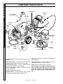
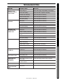
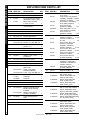
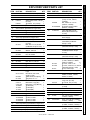
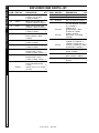
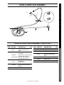
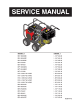
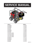
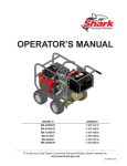
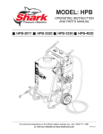
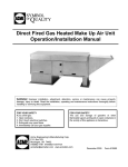
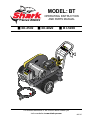
MODEL: BT
OPERATING INSTRUCTION
AND PARTS MANUAL
■ BT-3530
■ BT-4020
■ BT-5030
For technical assistance or the SHARK dealer nearest you
visit our website at www.shark-pw.com
#97-727
CONTENTS
Introduction ............................................................................................. 4
Important Safety Information ................................................................ 4-5
Component Identification ......................................................................... 6
Assembly Instructions ............................................................................. 7
Operating Instructions ............................................................................. 8
Detergents and General Operating Techniques ........................................ 9
Shut Down and Clean-Up ...................................................................... 10
Storage ................................................................................................. 10
Troubleshooting ................................................................................ 11-12
Preventative Maintenance ..................................................................... 13
Oil Change Record ................................................................................ 13
Exploded View .................................................................................. 14-15
Exploded View Parts List ................................................................. 16-18
Hose & Spray Gun ................................................................................ 19
Downstream Injector ............................................................................. 19
Specifications .................................................................................. 20-21
Warranty
Model Number ______________________________
Serial Number ______________________________
Date of Purchase ___________________________
The model and serial numbers will be found on a decal attached to
the pressure washer. You should record both serial number and
date of purchase and keep in a safe place for future reference.
3
97-727, 96-721 • REV. 4/05
PRESSURE WASHER
OPERATOR’S MANUAL
INTRODUCTION & IMPORTANT SAFETY INFORMATION
All information in this manual is based on the latest
product information available at the time of printing.
interrupter (GFCI) power cord (120V and 230V
1 ph). All other models must be connected to a
GFCI circuit breaker.
We reserve the right to make changes at any time
without incurring any obligation.
WARNING can create fumes which can ig-
Thank you for purchasing this Pressure Washer.
WARNING: Flammable liquids
nite causing property damage
or severe injury.
Owner/User Responsibility:
The owner and/or user must have an understanding of
the manufacturer’s operating instructions and warnings
before using this pressure washer. Warning information
should be emphasized and understood. If the operator is
not fluent in English, the manufacturer’s instructions and
warnings shall be read to and discussed with the operator in the operator’s native language by the purchaser/
owner, making sure that the operator comprehends its
contents.
RISK OF EXPLOSION:
DO NOT USE WITH
FLAMMABLE LIQUIDS.
WARNING
Owner and/or user must study and maintain for future
reference the manufacturers’ instructions.
This manual should be considered a permanent
part of the machine and should remain with it if
machine is resold.
When ordering parts, please specify model and
serial number.
IMPORTANT SAFETY
INSTRUCTIONS
WARNING: When using this machine, basic precautions should always be followed, including the
following:
CAUTION CAUTION: To reduce the risk of
injury, read operating instructions carefully before using.
READ OPERATOR’S
MANUAL
THOROUGHLY
PRIOR TO USE.
1. Read the owner's manual thoroughly. Failure to follow instructions could cause malfunction of the machine and
result in death, serious bodily
injury and/or property damage.
2. Know how to stop the machine and bleed pressures quickly. Be thoroughly familiar with the controls.
3. Stay alert — watch what you are doing.
4. All installations must comply with local codes. Contact your electrician, plumber, utility company or
the selling distributor for specific details.
To comply with the National Electrical Code (NFPA
70) and provide additional protection from risk of
electric shock, these pressure washers are
equipped with a UL approved ground fault circuit
WARNING: Risk of explosion —
do not spray flammable liquids.
5. Risk of explosion — do not
spray flammable liquids or
operate in an explosive location.
WARNING: Keep water spray
away from electric wiring or fatal electric shock may result.
6. To protect the operator from
electrical shock, the machine
must
be
electrically
KEEP WATER SPRAY
grounded. It is the responsiAWAY FROM
bility of the owner to connect
ELECTRICAL WIRING.
this machine to a UL
grounded receptacle of
proper voltage and amperage ratings. Do not spray
water on or near electrical components. Do not
touch machine with wet hands or while standing in
water. Always disconnect power before servicing.
7. Grip cleaning wand securely with both hands before starting the cleaner. Failure to do this could
result in injury from a whipping wand.
WARNING
WARNING: The high pressure
stream of fluid that this equipment can produce can pierce
skin and its underlying tissues,
leading to serious injury and
possible amputation.
8. High pressure developed by
these machines will cause
personal injury or equipment
damage. Use caution when
operating. Do not direct discharge stream at people, or severe injury or death
will result.
9. Never make adjustments on machine while in
operation.
RISK OF INJECTION
OR SEVERE INJURY
TO PERSONS. KEEP
CLEAR OF NOZZLE.
4
97-727, 96-721 • REV. 4/05
WARNING
USE PROTECTIVE
EYEWEAR WHEN
OPERATING.
WARNING: High pressure spray
can cause paint chips or other
particles to become airborne
and fly at high speeds.
10. Eye safety devices and foot
protection must be worn when
using this equipment.
OPERATOR’S MANUAL
11. Machines with spray gun
should not be operated with
the trigger in the off position for extensive periods
of time as this may cause damage to the pump.
12. Protect from freezing.
13. Be certain all quick coupler fittings are secured
before using pressure washer.
14. Do not allow acids, caustic or abrasive fluids to
pass through the pump.
15. Inlet water must be cold and clean fresh water.
16. To reduce the risk of injury, close supervision is
necessary when a machine is used near children.
Do not allow children to operate the pressure
washer. This machine must be attended during operation.
17. The best insurance against an accident is precaution and knowledge of the machine.
18. Manufacturer will not be liable for any changes
made to our standard machines or any components not purchased from us.
PRESSURE WASHER
IMPORTANT SAFETY INFORMATION
5
97-727, 96-721 • REV. 4/05
PRESSURE WASHER
OPERATOR’S MANUAL
COMPONENT IDENTIFICATION
Pump Protector
Detergent
Injector
Water Supply Hose
(not included)
Oil Level
Sight Glass
Oil
Dipstick
Start/Stop
Switches
Power
Supply
Inlet
Connector
GFCI
Detergent Bucket
(not included)
Pump
Detergent
Tube
Spray
Gun
Pressure Nozzle
Power
Cord
Nozzle
Quick
Coupler
Wand
Trigger
Soap
Nozzle
Swivel
Connector
High Pressure Hose
Detergent Injector - Allows you to siphon and mix detergents.
Spray Gun - Must be connected to the high pressure
hose and wand.
High Pressure Hose - Connect one end to water pump
discharge nipple and the other end to spray gun.
Swivel Connector - Connects to the spray gun and
wand. Minimizes hassle of hose coiling.
Nozzle Quick Coupler - To easily connect the high
pressure hose and soap nozzle to wand.
Wand - Must be connected to the spray gun.
Oil Level Sight Glass - A quick visual reference to the
oil level in the pump.
Pump - Develops high pressure.
Pump Protector - Cycles fresh cool water through
pump when recirculating water reaches 140°F.
Note: If trigger on spray gun is released for more
than 2 minutes, water will leak from valve. Warm
water will discharge from pump protector onto
floor. This system prevents internal pump damage.
6
97-727, 96-721 • REV. 4/05
Spray
Gun
Pressure
Nozzle
Pressure
Nozzle
Safety
Latch
Wand
Coupler
Wand
Coupler
Wand
Collar
High Pressure
Hose
STEP 2: Pull the spring-loaded collar of the wand coupler back to insert your choice of pressure nozzle.
Pump
Discharge
Fitting
DipStick
STEP 3: Release the coupler collar and push the nozzle until the
collar clicks. Pull the nozzle to
make sure it is seated properly.
Cold
Water
Source
High
Pressure
Hose
Coupler Collar
STEP 4: Remove shipping cap and
install oil dipstick. Check pump oil
level by using dipstick or observe oil
level in oil window (if equipped). Use
30 wt. non detergent oil.
STEP 5: Connect the high pressure
hose to the pump discharge fitting.
Push coupler collar forward until
secure.
OPERATOR’S MANUAL
STEP 1: Attach the high pressure
hose to the spray gun using teflon
tape on hose threads.
PRESSURE WASHER
ASSEMBLY INSTRUCTIONS
Garden
Hose
STEP 6: Connect garden hose to
the cold water source.
Pump
Water Inlet
Garden
Hose
STEP 7: Check inlet filters, remove
debris, then connect the garden
hose to pump water inlet.
CAUTION: Do not run the pump
without water or pump damage
will result.
7
97-727, 96-721 • REV. 4/05
OPERATOR’S MANUAL
PRESSURE WASHER
OPERATING INSTRUCTIONS
Cold
Water
Source
Garden
Hose
STEP 1: Connect garden hose to the
cold water source and turn water on
completely. Never use hot water.
STEP 2: Trigger the spray gun to
eliminate trapped air then wait for a
steady flow of water to emerge from
the spray nozzle.
Safety
Latch
STEP 4: Turn machine on.
WARNING! Never replace
nozzles without engaging the
safety latch on the spray gun trigger.
NOZZLES
The five color-coded quick connect nozzles provide a wide array of spray
widths from 0° to 45° and are easily accessible when placed in the convenient rubber nozzle holder, which is provided on the front of the machine.
NOTE: For a more gentle rinse, select the white 40° or green 25° nozzle.
To scour the surface, select the yellow 15° or red 0° nozzle. To apply detergent select the black nozzle.
8
97-727, 96-721 • REV. 4/05
STEP 3: Connect machine to adequate power source. Push reset
button on GFCI.
WARNING
WARNING: Some detergents may
be harmful if inhaled or ingested,
causing severe nausea, fainting
or poisoning. The harmful elements may cause property damage or severe injury.
Soap
Nozzle
Quick
Coupler
Filter
Discharge
Nipple
Detergent
Injector
If you run the engine on your pressure washer for 3-5
minutes without pressing the trigger on the spray gun,
circulating water in the pump can reach high temperatures. When the water reaches this temperature, the
pump protector engages and cools the pump by discharging the warm water onto the ground. This thermal
device prevents internal damage to the pump.
CLEANING TIPS
Pre-rinse cleaning surface with fresh water. Place detergent suction tube directly into cleaning solution and apply to surface at low pressure (for best results, limit
your work area to sections approximately 6 feet square
and always apply detergent from bottom to top). Allow
detergent to remain on surface 1-3 minutes. Do not allow detergent to dry on surface. If surface appears to
be drying, simply wet down surface with fresh water. If
needed, use brush to remove stubborn dirt. Rinse at
high pressure from top to bottom in an even sweeping
motion keeping the spray nozzle approximately 1 foot
from cleaning surface. Use overlapping strokes as you
clean and rinse any surface. For best surface cleaning
action spray at a slight angle.
OPERATOR’S MANUAL
STEP 1: Connect detergent injector to discharge nipple
on machine, Connect high pressure hose to injector
with quick coupler. (Check to make sure locking coupler sleeves are in proper position before applying water pressure.)
THERMAL PUMP PROTECTION
PRESSURE WASHER
DETERGENTS AND GENERAL CLEANING TECHNIQUES
Recommendations:
High Pressure Hose
STEP 2: Use detergent designed
specifically for pressure washers.
Household detergents could damage the pump. Prepare detergent solution as required by the manufacturer. Fill a container with pressure
washer detergent. Place the filter
end of detergent suction tube into
the detergent container.
STEP 3: With safety latch on spray gun engaged, secure black detergent nozzle into quick coupler.
NOTE: Detergent cannot be applied using red, yellow,
green or white nozzles.
STEP 4: With the engine running,
pull trigger to operate machine.
Liquid detergent is drawn into the
machine and mixed with water.
Apply detergent to work area. Do
not allow detergent to dry on surface.
• Before cleaning any surface, an inconspicuous area
should be cleaned to test spray pattern and distance for maximum cleaning results.
• If painted surfaces are peeling or chipping, use extreme caution as pressure washer may remove the
loose paint from the surface.
• Keep the spray nozzle a safe distance from the surface you plan to clean. High pressure wash a small
area, then check the surface for damage. If no damage is found, continue to pressure washing.
CAUTION - Never use:
• Bleach, chlorine products and other corrosive
chemicals
• Liquids containing solvents (i.e., paint thinners,
gasoline, oils)
• Tri-sodium phosphate products
• Ammonia products
• Acid-based products
These chemicals will harm the machine and will damage the surface being cleaned.
RINSING
IMPORTANT: You must flush the detergent injection
system after each use by placing the suction tube
into a bucket of clean water, then run the pressure
washer in low pressure for 1-2 minutes.
It will take a few seconds for the detergent to clear. Apply
safety latch to spray gun. Remove black soap nozzle
from quick coupler. Select and install desired high pressure nozzle. NOTE: You can also stop detergent from
flowing by removing detergent siphon tube from bottle.
97-727, 96-721 • REV. 4/05
9
OPERATOR’S MANUAL
PRESSURE WASHER
SHUTTING DOWN AND CLEAN-UP
STEP 1: Remove detergent suction
tube from container and insert into
one gallon of fresh water. Slide
nozzle forward for low pressure or
to connect black detergent nozzle.
Pull trigger on spray gun and siphon
water for one minute.
STEP 3: Turn off water
supply.
STEP 2: Turn off machine.
High
Pressure
Outlet
Safety
Latch
Pump
Water
Inlet
STEP 4: Press trigger to release water pressure.
STEP 5: Disconnect the garden
hose from the water inlet on the
machine.
STEP 6: Disconnect the high
pressure hose from high pressure outlet.
STORAGE
Pump Storage
CAUTION
CAUTION: Always store your pressure washer in a location where the
temperature will not fall below 32° F
(0° C). The pump in this machine is
susceptible to permanent damage if
frozen.
FREEZE DAMAGE IS NOT COVERED BY WARRANTY.
If you must store your pressure washer in a location
where the temperature is below 32° F, you can minimize the chance of damage to your machine by draining your machine as follows:
1. Stop the pressure washer and detach supply hose
and high pressure hose. Squeeze the trigger of the
spray gun to drain all water from the wand and
hose.
2. Restart pressure washer and let it run briefly (about
5 seconds) until water no longer discharges from
the high pressure outlet.
10
97-727, 96-721 • REV. 4/05
STEP 7: Engage
the spray gun
safety lock.
PROBLEM
POSSIBLE CAUSE
SOLUTION
PUMP RUNNING
NORMALLY BUT
PRESSURE LOW ON
INSTALLATION
Pump sucking air
Check water supply and possibility of air seepage.
Check valves sticking
Check and clean or replace if necessary.
Unloader valve seat faulty
Check and replace if necessary.
Nozzle incorrectly sized
Check and replace if necessary.
Worn piston packing
Check and replace if necessary.
Valves worn
Check and replace if necessary.
Blockage in valve
Check and clean out if necessary.
Pump sucking air
Check water supply connections.
Worn piston packing
Check and replace if necessary.
Insufficient water
Check filter and hose for breakage.
Nozzle worn
Check and replace if necessary.
Suction or delivery valves worn
Check and replace if necessary.
Suction or delivery valves
blocked
Check and clean if necessary.
Unloader valve seat worn
Check and replace if necessary.
Worn piston package
Check and replace if necessary.
Air in suction line
Check water supply and connections on suction line.
Broken or weak suction or
delivery valve spring
Check and replace if necessary.
Foreign matter in valves
Check and clean if necessary.
Worn bearings
Check and replace if necessary.
Excessive temperature of water
Reduce to below 140o F.
Oil seal worn
Check and replace if necessary.
High humidity in air
Check and change oil twice as often.
Piston packing worn
Check and replace if necessary.
WATER DRIPPING
FROM UNDER PUMP
Piston packing worn
Check and replace if necessary.
O-Ring plunger retainer worn
Check and replace if necessary.
WATER DRIPPING
FROM PUMP
PROTECTOR
Water supply pressure too high
(over 90 psi)
Spray gun is in the off position
for over 5 minutes
Lower water supply pressure using a regulator.
FLUCTUATING
PRESSURE
PRESSURE LOW
AFTER PERIOD OF
NORMAL USE
PUMP NOISY
PRESENCE OF WATER
IN PUMP OIL
PRESSURE WASHER TROUBLESHOOTING GUIDE
TROUBLESHOOTING
Turn machine off if not in use for over 5 minutes.
OIL DRIPPING
Oil seal worn
Check and replace if necessary.
EXCESSIVE VIBRATION
IN HIGH-PRESSURE
HOSE
Irregular functioning of the
pump valves
Check and replace if necessary.
11
97-727, 96-721 • REV. 1/05
PROBLEM
POSSIBLE CAUSE
SOLUTION
MOTOR WILL NOT
START
Usually caused by line trouble, such
as single phasing at the starter
Check source of power. Check overloads,
fuses, controls, etc.
MOTOR OVERHEATING
Overload. Compare actual amps
(measured) with nameplate rating
Locate and remove source of excessive
friction in motor or load.
Reduce load or replace with motor of greater
capacity.
Single phasing
Check current at all phases (should be
approximately equal) to isolate and correct
problem.
Improper ventilation
Check external cooling fan to be sure air is
moving properly across cooling fins.
Excessive dirt build-up on motor. Clean motor.
Unbalanced voltage
Check voltage at all phases (should be
approximately equal) to isolate and correct the
problem.
Over voltage or under voltage
Check input voltage at each phase to motor.
Open stator winding
Check stator resistance at all three phases for
balance.
Improper connections
Inspect all electrical connections for proper
termination, clearance, mechanical strength
and electrical continuity. Refer to wiring
diagrams.
Misalignment
Check and align motor and driven equipment.
Excessive belt tension
Reduce belt tension to proper point for load.
Excessive grease in bearing
Remove grease until cavity is approximately
3/4 filled.
Insufficient grease in bearing
Add grease until cavity is approximately 3/4
filled.
Dirt in bearing
Clean bearing cavity and bearing. Repack with
correct grease until cavity is approximately 3/4
filled.
Bad bearing
Replace bearing. Clean all grease from cavity
and new bearing. Repack with correct grease
until cavity is approximately 3/4 filled.
PRESSURE WASHER
TROUBLESHOOTING GUIDE
TROUBLESHOOTING
BEARING
OVERHEATING
GROWLING OR
WHINING
12
97-727, 96-721 • REV. 1/05
This pressure washer was produced with the best available materials and quality craftsmanship. However, you
as the owner have certain responsibilities for the correct care of the equipment. Attention to regular preventative
maintenance procedures will assist in preserving the performance of your equipment. Contact your dealer for
maintenance. Regular preventative maintenance will add many hours to the life of your pressure washer. Perform maintenance more often under severe conditions.
Inspect
Daily inspect the oil level
Change
After first 50 hours, then every 500 hours or annually
Pump Oil
Every 6 months
Replace Quick Connects
Anually
Clean Water Screen/Filter
Weekly
Replace HP Hose
Anually if there is any sign of wear
Grease Motor
Every 10,000 hours or annually
OPERATOR’S MANUAL
Replace High Pressure Nozzle
PRESSURE WASHER
PREVENTATIVE MAINTENANCE
General Inspection
Inspect the motor at regular intervals, approximately every 500 hours of operation,
or every 3 months, whichever occurs first. Keep the motor clean and the ventilation
openings clear. The following steps should be performed at each inspection:
WARNING: Do not touch electrical connections before you first ensure that power
has been disconnected. Electrical shock can cause serious or fatal injury. Only qualified personnel should attempt the installation, operation and maintenance of this
equipment.
1. Check that the motor is clean. Check that the interior and exterior of the motor
is free of dirt, oil, grease, water, etc. Oily vapor, paper pulp, textile lint, etc. can
accumulate and block motor ventilation. If the motor is not properly ventilated
overheating can occur and cause early motor failure.
2. Check all electrical connectors to be sure that they are tight.
Lubrication & Bearings
Bearing grease will lose its lubricating ability over time, not suddenly. The lubricating
ability of a grease (over time) depends primarily on the type of grease, the size of the
bearing, the speed at which the bearing operates and the severity of the operating
conditions. Good results can be obtained if the following recommendations are used in
your maintenance program.
Type of Grease
A high grade ball or roller bearing grease should be used. Recommended greases for
standard service conditions are: Shell Dolium R (Factory installed) or Chevron SRI.
OIL CHANGE RECORD
Date Oil Changed
Month/Day/Year
Estimated Operating
Hours Since Last
Oil Change
Date Oil Changed
Month/Day/Year
Estimated Operating
Hours Since Last
Oil Change
13
97-727, 96-721 • REV. 4/05
97
Model PE3-1100
71
65
35
62
74
57
47
98
65
63
64
28
46
63
23
53
73
46
58
52
OPERATOR’S MANUAL
PRESSURE WASHER
EXPLODED VIEW
92
37
51
61
54
25
60
46
36
BB353007A,
BT353007A,
PE4-3000A
25
59
24
27
45
29
44
36
68
21
42, 95, 96
66
45
37
64
44
70
29
69
65
63
5
1
99
75
48
75
2
18
5
23
67
5
3
5
2
48
48
46
4
5
90
89
5
6
47
6
2
5
5
3
48
91
5
7
6
5
43
9
2
9
76
5
8
91
7
76
43
14
97-727, 96-721 • REV. 4/05
1
PRESSURE WASHER
EXPLODED VIEW
40
26
26
22 34
22
41
41
33
78
34
OPERATOR’S MANUAL
33
BT & BB Models
353007, 402007,
503007 - PE Models
4-20021, 4-30021,
5-30021
40
72
72
PE3-11021D
32
94
30
31
20
82
40
83
79
80
93
84
41
34
26
88
99
85
19
78
87
81
6
86
6
22
5
PE4-20024,
4-30024, 5-30024
6
5
5
6
5
17
14
15
11
16
12a
13
10
5
6
12b
15
97-727, 96-721 • REV. 4/05
PRESSURE WASHER
OPERATOR’S MANUAL
EXPLODED VIEW PARTS LIST
PART NO.
DESCRIPTION
QTY
ITEM
1
90-2004
Nut, Jam, ESNA, NC, 5/8"
2
27
2
90-4005
Washer, Flat, SAE, 5/8"
4
3
4-0307
Tire & Wheel Cmpl, Steel 6"
(All Models except 3-1100)
2
Wheel & Tire Assembly,
4" Tube, (3-1100)
2
ITEM
4-0303
95-07101130
Handle, Bumper, 1-1/4",
Chrome Plated
1
5
90-4002
Washer, Flat, SAE, 3/8"
30
6
90-2002
Nut, ESNA, NC, 3/8"
14
7
90-10220
Bolt, 3/8" x 3-1/2", Tap
2
8
95-07101135
Bracket, Belt Tension
1
9
90-2020
Nut, Cage, 3/8", 12 Gauge
2
10
95-07101219
Bracket, Foot, Black (PE)
95-07101219R Bracket, Foot, Red (BB, BT)
11
92-102
2
12a
90-1023
Bolt, 3/8" x 5", NC
2
12b
90-40125
Washer, 3/8" x 1", Steel
2
13
2-01041
Pad, Soft Rubber
2
14
90-4015
Washer, 2-1/2" x 7/16",
Flat Washer
2
15
95-07161114A Tube, Foot, Bolt PC
2
16
90-5009
Spring, Foot, Compression
2
17
2-0107
Bellows, Leg (Boot)
2
18
95-07101216
Frame, Black, Welded
(PE3-1100)
95-07101222
Frame, Large, Black,
Welded (PE Models)
95-07101222R Frame, Large, Red (BB, BT)
1
1
11-0364
11-0331
10-99060
1
1
1
95-07101145
Handle, 1-1/4", Chrome
1
6-05172
Locknut, 3/4"
2
22
2-2007
Nipple, 3/4" x 3/8" Male
1
23
95-07101021
Bracket, Electrical Box (All
Models except 353007A,
4-3000A)
Bracket, Electrical Box
(353007A, 4-3000A)
1
Label, Warning Service
Cord
1
Cushion, Pump
2
10-08018
25
2-0106
26
See Unloader Specifications, Pages 20-21
6-010690
6-01021
28
6-0108
6-0104
6-0105
6-0109
6-0102
6-01021
29
6-051595
6-05170
21
24
6-01059
1
20
95-07101022
Cord, w/GFCI, 120V/20 Amp,
36' (3-1100)
1
Cord, Service 12/4 (353007C;
4-2000B,C; 402007B,C; 43000C,
N;503007C; 5-3000C)
15 ft.
Cord w/GFCI, 240V/30Amp
36' (4-2000A; 402007A)
1
Cord, Service,10/4
(353007B; 4-3000B)
15 ft.
GFCI, 240V, 40A, 1 PH, 37'
Cord (353007A; 4-3000A)
1
Cord, Service, 8/4
(503007B; 5-3000B)
15 ft.
6-0105
1
1
Foot Assembly
(Items 11-17)
Label, BT
Label, BB
Label, PE
DESCRIPTION
6-0109
4
19
PART NO.
6-01060
Fitting, STRT, LQ Tite, Plastic
(353007B,C; 402007A,B,C;
4-2000A,B,C;4-3000B,C,N;
5-3000C; 503007C)
2
Strain Relief, Water Tight
(5-3000B, 503007B)
2
2-0103
Grommet, Rubber, 1/8"
31
4-12804000
Nozzle, SAQC MEG 0004
Red (4-3000; 3530)
Nozzle, SAQC MEG 1504
Yellow (4-3000; 3530)
Nozzle, SAQC MEG 2504
Green (4-3000; 3530)
Nozzle, SAQC MEG 4004
White (4-3000; 3530)
4-12804025
4-12804040
4-12805500
1
Cord, Service, SEO, 10/3
(402007A; 4-2000A)
2.75 ft.
Cord Service SEO, 12/3
(3-1100)
2 ft.
Cord, Service, SEO, 12/4
(353007C; 402007B,C;
4-2000B,C; 4-3000C,N;
5-3000C; 503007C)
2.75 ft.
Cord, Service, SEO, 10/4
(353007B; 4-3000B)
2.75 ft.
Cord, Service SEO 8/3
(353007A; 4-3000A)
4 ft.
Cord, Service SEO, 8/4
(5-3000B; 503007B)
2.75 ft.
30
4-12804015
4-12805515
4-12805525
4-12805540
4-12806000
4-12806015
4-12806025
4-12806040
16
97-727, 96-721 • REV. 4/05
QTY
5
1
1
1
1
Nozzle SAQC MEG 0005.5
Red (3-1100, 5030, 5-3000) 1
Nozzle, SAQC MEG 15055
Yellow (3-1100; 5030; 5-3000)1
Nozzle, SAQC MEG 25055
Green (3-1100; 5030; 5-3000)1
Nozzle, SAQC MEG 4055 White
(3-1100; 5030; 5-3000)
1
Nozzle, SAQC MEG 0506
Red (4-2000; 4020)
Nozzle, SAQC MEG 1506
Yellow (4-2000; 4020)
Nozzle, SAQC, Meg 2506
Green (4-2000; 4020)
Nozzle, SAQC MEG 4006
White (4-2000; 4020)
1
1
1
1
ITEM
PART NO.
DESCRIPTION
QTY
ITEM
32
4-16540
Nozzle, Brass, Soap
1
61
See Belt Specifications, Pages 20-21
33
2-1902
Strainer, Inlet Garden Hose
1
62
6-03911
Lid, Plastic, Carlon (3-1100) 1
34
2-10942
Swivel, 1/2" MP x 3/4" GHF
1
63
6-03904
35
6-05154
Strain Relief, Plastic, LQ Tite
(3-1100)
1
▲ Locknut, 1/2” (3-1100)
1
Enclosure, Fiberglass, Nema4X
(except 3-1100, 35007A,
4-3000A)
1
Box, Plastic 10" x 8" x 6"
(35007A, 4-3000A)
1
▲ Standoff, Electrical Box
(35007A, 4-3000A)
1
6-05181
See Overload Specifications, Pages 20-21
37
See Contactor Specifications, Pages 20-21
38
90-1991
▲ Screw, 10/32" x 1/2"
6
39
90-017
▲ Nut, 10/32" Keps
4
40
2-30082
Pump Protector, 1/2", PTP
1
41
See Pump Specifications, Pages 20-21
42
See Motor Specifications, Pages 20-21
43
90-1007
90-1017
95-07290068
4
Washer, 5/16" Flat (3-1100)
Washer, 3/8" Flat
4
4
45
90-2001
90-2002
Nut, 5/16" ESNA (3-1100)
Nut, 3/8" ESNA
4
4
46
90-4001
Washer, 5/16" Flat
6
47
90-2001
Nut, 5/16" ESNA, NC
3
48
90-1020
Bolt, 3/8" x 2", NC HH
8
49
90-4000
▲ Washer, 1/4" Flat, SAE
4
50
90-2000
▲ Nut, 1/4" ESNA, NC
2
51
90-1006
Bolt, 5/16" x 3/4", NC HH
1
52
95-07101211
90-5004
90-1028
Back Plate, Belt Guard,
Large
Back Plate, Belt Guard,
Small (3-1100)
▲ Belt Guard, Pull Spring
▲ Eyebolt, 1/4" x 1"
1
1
2
2-01171
2-01172
2-0117201
10-99055
11-0332
11-0330
Belt Guard, Small (3-1100)
Belt Guard, Large (PE)
Belt Guard, Large (BB, BT)
▲ Label (PE)
▲ Label (BT)
▲ Label (BB)
1
1
1
1
1
1
90-1007
Bolt, 5/16" x 1" NC, HH
2
54
1
55
10-020PE
▲ Label, PE
1
56
10-2031100
10-2042000
10-2043000
10-2053000
▲
▲
▲
▲
1
1
1
1
Label,
Label,
Label,
Label,
3-1100
4-2000
4-3000
5-3000
65
10-08015A
10-08021
6-2021
4
90-4001
90-4002
53
64
66
Bolt, 5/16" x 1", NC HH
(3-1100)
Bolt, 3/8" x 1-1/4", NC HH
(All Models Except 3-1100)
44
95-07101213
6-03909
57
See Pump Bushing Specifications, Pages 20-21
58
See Motor Bushing Specifications, Pages 20-21
59
See Motor Pulley Specifications, Pages 20-21
60
See Pump Pulley Specifications, Pages 20-21
DESCRIPTION
QTY
Label, OFF/ON for Push
Button (All Models Except
3-1100)
1
Label, Disconnect
Power Supply
1
Switch, Green Push Button,
CH E22PB3 (All Models
Except 3-1100)
1
67
6-2001
Block, Contact, N/O, CH E22B2
(All Models Except 3-1100) 1
68
6-2022
Switch, Red Push Button, CH
E22EB2(All Models Except
3-1100)
1
69
6-2000
Block, Contact, N/C, CH E22B1
(All Models Except 3-1100) 1
70
6-021595
90-017
Din Rail (All Models Except
(3-1100, 353007A, 4-2000A,
42007A, 4-3000A)
4"
▲ Screw, 10/32" x 1/2"
1
▲ Screw, 10/32"x1-1/4", Ground
(All Models Except 3-1100) 1
▲ Nut, 10/32" Keps
3
71
6-03910
Box, Electric (3-1100 only)
72
2-1044
Plug, Brass 1/8"(3-1100,353007,
402007, 4-20021, 4-30021,
503007, 5-30021)
1
73
6-051595
Strain Relief, STRT, LQ Tite
Large, 3/4" (3-1100)
▲ Locknut, 3/4” (3-1100)
1
1
Switch, 2 Pos., 1-3 PH
(3-1100)
1
90-1016
Bolt, 3/8" x 1", NC
4
76
90-2007
Nut, 3/8" Hex NC
2
77
11-1042
▲ Label, Ground
1
78
2-1042
Tee, 1/2" (3-11021, 4-20024,
4-30024, 5-30024)
1
79
2-02110000
Hose, 1/2" Push-On (4-20024,
4-30024, 5-30024)
1.3 ft.
80
2-1105
Swivel, 1/2" JIC Fem, Push-On
(4-20024, 4-30024, 5-30024) 2
81
2-1062
Elbow, 1/2" JIC x 1/2", 90°
(4-20024, 4-30024, 5-30024) 1
90-1991
90-1994
6-05172
74
75
6-020204
OPERATOR’S MANUAL
36
PART NO.
PRESSURE WASHER
EXPLODED VIEW PARTS LIST
1
17
97-727, 96-721 • REV. 4/05
PRESSURE WASHER
OPERATOR’S MANUAL
EXPLODED VIEW PARTS LIST
ITEM
PART NO.
DESCRIPTION
82
4-02047720
Hose, 3/8" x 20", 2 Wire,
Pressure Loop (4-20024,
4-30024, 5-30024)
QTY
1
83
2-0053
Elbow, 1/2" JIC x 3/8", 90°
(4-20024, 4-30024, 5-30024) 1
84
2-0051
Nipple, 1/2" JIC x 3/8", Pipe
(4-20024, 4-30024, 5-30024) 1
85
2-0006
Nipple, 3/8", Hex (4-20024,
4-30024, 5-30024)
87
2-1060
Elbow, 1/2" x 3/8", 90° (4-20024,
4-30024, 5-30024)
1
88
90-1020
Bolt, 3/8" x 2", NC HH (4-20024,
4-30024, 5-30024)
2
89
90-10343
Bolt, 10mm x 20mm, HH (All
Models except 3-11021,
4-20021, 4-30021, 5-30021) 4
91
90-4007
90-4006
DESCRIPTION
6-05172
▲ Locknut, 3/4” Conduit
2
93
95-07102382
Hanger, Hose & Wand
1
94
90-20012
Nut, 5/16" Whiz Loc, Flange 2
95
6-051595
Strain Relief, Watertite
(3-1100D;353007B, C;4-2000A,
B, C; 4-3000B, C;
402007A, B, C)
1
▲ Strain Relief, 1" Metal
(4-3000A, N; 5-3000C;
503007C; 35300A)
1
Strain Relief, 1” (5-3000B,
503007B)
1
6-051700
95-07101216/B Block, Unloader, 3/8" x 3/8",
Brass (4-20024, 4-30024,
5-30024)
90-400910
PART NO.
92
1
86
90
ITEM
6-051701
1
Washer, 7/16" Lock, Split(All
Models except 3-11021,
4-20021, 4-30021, 5-30021) 4
96
6-05181B
6-05182
97
98
99
6-05170
6-051595
9.800-049.0
Washer, 3/8" x 1-1/2",
Fender (All Models Except
3-1100)
6
Washer, 5/16” x 1-1/4” Fender
(3-1100)
6
18
97-727, 96-721 • REV. 4/05
QTY
Lock Nut, 3/4" (3-1100D;
353007B, C; 4-2000A, B, C;
4-3000B, C; 402007A, B, C) 1
Locknut, 1” (353007A; 4-3000A,
N; 503007B,C; 5-3000B, C) 1
Strain Relief, 3/4 Watertight
(3530A, 4-3000A)
1
Strain Relief, 3/4 Watertight
Plastic (3530A, 4-3000A)
1
Label, Manufacturer’s Cleaning
Solution
1
▲ Not Shown
PRESSURE WASHER
HOSE & SPRAY GUN ASSEMBLY
1
8
10
7
11
12
6
OPERATOR’S MANUAL
11
3
4,5
9
2
HOSE & SPRAY GUN ASSEMBLY PARTS LIST
ITEM
1
2
3
PART NO.
DESCRIPTION
2-2002
2-0121
Coupler, 3/8" Female
▲ Quick Coupler O-Ring
Large
QTY
ITEM
1
6
1
4-02043450C
Hose 3/8” x 50’ w/Coupler
(PE Models)
1
4-020650C
Hose 3/8” x 50’ 1 Wire Pressure,
w/Coupler (BB Models)
1
4-02093450BC Hose 3/8” x 50’ 1 Wire Blue,
w/Coupler (BT Models)
1
4-01212
4-01246
Spray Gun, Shut-off
(PE Models)
BB &BT Models
1
1
4
4-0110410
4-0110322
Wand, Straight (PE Models) 1
Wand w/side Grip ( BB & BT
Models)
1
5
4-011231
Cover, Wand (PE Models)
PART NO.
DESCRIPTION
4-16540
Brass Soap Nozzle
QTY
1
7
Nozzle, See Page 16, Item #31
8
4-011184
Detergent Injector (3-5 GPM) 1
9
2-2000
2-0119
Coupler, 1/4" Female
▲ Quick Coupler O-Ring
Small
10
4-02080000
Tube, 1/4” x 1/2” Clear Vinyl 6 ft.
11
2-9040
Clamp, Hose
2
12
2-1904
Strainer, 1/4” Hose Barb
1
1
1
▲ Not Shown
1
19
97-727, 96-721 • REV. 4/05
PRESSURE WASHER SPECIFICATIONS
SPECIFICATIONS
PARTS SPECIFICATIONS
PUMP
MOTOR
Pump Unloader
Pump
Pump Pulley
Pump
Part No. Part No.
Pulley
Part No.
Bushing
Bushing Motor
Part No.
Motor
Model
Pump
Size Voltage/ph
Hz
4-20024A
LT5030
5-1728
5-3208
2AK84H
5-40208401
4-20024B
LT5030
5-1728
5-3208
2AK84H
5-40208401
25MM
5-512025 6.2HP 230V/1PH
60
25MM
5-512025 6.2HP 230V/3PH
60
4-20024C
LT5030
5-1728
5-3208
2AK84H
5-40208401
25MM
5-512025 6.2HP 460V/3PH
60
4-30024A
LT5030
5-1728
5-3208
4-30024B
LT5030
5-1728
5-3208
2BK90H
5-40509001
25MM
5-512025 7.5HP 230V/1PH
60
2BK90H
5-40509001
25MM
5-512025 7.5HP 230V/3PH
60
4-30024C
LT5030
5-1728
5-3208
2BK90H
5-40509001
25MM
5-512025 7.5HP 460V/3PH
60
4-30024N
LT5030
5-1728
5-3208
2BK70H
5-40507001
25MM
5-512025 7.5HP 380V/3PH
50
5-30024B
LT5030
5-1728
5-3208
2BK65H
5-40506501
25MM
5-512025
10HP 230V/3PH
60
5-30024C
LT5030
5-1728
5-3208
2BK65H
5-40506501
25MM
5-512025
10HP 460V/3PH
60
402007A
GM4030
5-1910
5-3029
2AK74H
5-40207401
24MM
5-512024 6.2HP 230V/1PH
60
402007B
GM4030
5-1910
5-3029
2AK74H
5-40207401
24MM
5-512024 6.2HP 230V/3PH
60
402007C
GM4030
5-1910
5-3029
2AK74H
5-40207401
24MM
5-512024 6.2HP 460V/3PH
60
353007A
GM4030
5-1910
5-3029
2BK70H
5-40507001
24MM
5-512024 7.5HP 230V/1PH
60
353007B
GM4030
5-1910
5-3029
2BK70H
5-40507001
24MM
5-512024 7.5HP 230V/3PH
60
353007C
GM4030
5-1910
5-3029
2BK70H
5-40507001
24MM
5-512024 7.5HP 460V/3PH
60
503007B
GM5030
5-1915
5-3029
2BK52H
5-40505201
24MM
5-512024
10HP 230V/3PH
60
503007C
GM5030
5-1915
5-3029
2BK52H
5-40505201
24MM
5-512024
10HP 460V/3PH
60
SPECIFICATIONS: GENERAL PUMP
PUMP
Model
3-11021D
Pump
T-991
MOTOR
Pump Unloader
Pump
Pump Pulley
Part No. Part No.
Pulley
Part No.
AK84H
5-40108401
5-2302
5-3025
Pump
Bushing
B u s h i n g Part No.
24MM
5-512024
Motor
Motor
S i z e Vo l t ag e / p h
Hz
2HP
120V/1PH
60
4-20021A
T-1011
5-2304
5-3025
2AK51H
5-40205101
24MM
5-512024
6.2HP
230V/1PH
60
4-20021B
T-1011
5-2304
5-3025
2AK51H
5-40205101
24MM
5-512024
6.2HP 230V/3PH
60
4-20021C
T-1011
5-2304
5-3025
2AK51H
5-40205101
24MM
5-512024
6.2HP 460V/3PH
60
4-30021A
TS-2021
5-2307
5-3025
2BK80H
5-40508001
24MM
5-512024
7.5HP
230V/1PH
60
4-30021B
TS-2021
5-2307
5-3025
2BK80H
5-40508001
24MM
5-512024
7.5HP
230V/3PH
60
4-30021C
TS-2021
5-2307
5-3025
2BK80H
5-40508001
24MM
5-512024
7.5HP
60V/3PH
60
5-30021B
TS-2021
5-2307
5-3025
2BK50H
5-40505001
24MM
5-512024
10HP
230V/3PH
60
5-30021C
TS-2021
5-2307
5-3025
2BK50H
5-40505001
24MM
5-512024
10HP
460V/3PH
60
20
97-727, 96-721 • REV. 4/05
MOTOR (CON'T)
Motor
Motor
Pulley
Motor
Bushing
Belt
Belt
Contactor
Overload
Model
Model
Pulley
Part No.
Bushing
Part No.
Size
Part No.
Part No.
Part No.
4-20024A
5-10401
4-20024B
5-1011
2AK46H
5-40204601
HX1-1/8"
5-511113
AX42 (2)
5-602042
6-4019
N/A
2AK46H
5-40204601
HX1-1/8"
5-511113
AX42 (2)
5-602042
6-4011
6-5011
4-20024C
5-1011
2AK46H
5-40204601
HX1-1/8"
5-511113
AX42 (2)
5-602042
6-4009
6-5009
4-30024A
5-1013
2BK40H
5-40504001
HX1-3/8"
5-511138
BX42 (2)
5-604042
6-4019
6-5015
4-30024B
5-10145
2BK40H
5-40504001
HX1-3/8"
5-511138
BX42 (2)
5-604042
6-4011
6-5012
4-30024C
5-10145
2BK40H
5-40504001
HX1-3/8"
5-511138
BX42 (2)
5-604042
4-4009
6-5009
4-30024N
5-1063
2BK34H
5-40503401
HX1-3/8"
5-511138
BX39 (2)
5-604039
6-40111
5-5010
5-30024B
5-1018
2BK36H
5-40503601
HX1-3/8"
5-511138
BX38 (2)
5-604038
6-4014
6-5013
5-30024C
5-1018
2BK36H
5-40503601
HX1-3/8"
5-511138
BX38 (2)
5-604038
6-4009
6-5010
402007A
5-10401
2AK46H
5-40204601
HX1-1/8"
5-511113
AX40 (2)
5-602040
6-4019
N/A
402007B
5-1011
2AK46H
5-40204601
HX1-1/8"
5-511113
AX40 (2)
5-602040
6-4011
6-5011
402007C
5-1011
2AK46H
5-40204601
HX1-1/8"
5-511113
AX40 (2)
5-602040
6-4009
6-5009
353007A
5-1013
2BK36H
5-40503601
HX1-3/8"
5-511138
BX37 (2)
5-604037
6-4019
6-5015
353007B
5-10145
2BK36H
5-40503601
HX1-3/8"
5-511138
BX37 (2)
5-604037
6-4011
6-5012
353007C
5-10145
2BK36H
5-40503601
HX1-3/8"
5-511138
BX37 (2)
5-604037
4-4009
6-5009
503007B
5-1018
2BK45H
5-40504501
HX1-3/8"
5-511138
BX36 (2)
5-604036
6-4014
6-5013
503007C
5-1018
2BK45H
5-40504501
HX1-3/8"
5-511138
BX36 (2)
5-604036
6-4009
6-5010
PRESSURE WASHER SPECIFICATIONS
SPECIFICATIONS
MOTOR (CON'T)
Motor
Motor
Pulley
Model
Model
Pulley
Part No.
3-11021D
5-1047
AK28X5/8"
4-20021A
5-10401
2AK32H
5-40203201
HX1-1/8"
5-511113
AX35 (2)
5-602035
6-4019
N/A
4-20021B
5-1011
2AK32H
5-40203201
HX1-1/8"
5-511113
AX35 (2)
5-602035
6-4011
6-5011
4-20021C
5-1011
2AK32H
5-40203201
HX1-1/8"
5-511113
AX35 (2)
5-602035
6-4009
6-5009
4-30021A
5-1013
2BK45H
5-40504501
HX1-3/8"
5-511138
BX42 (2)
5-604042
6-4019
6-5015
4-30021B
5-10145
2BK45H
5-40504501
HX1-3/8"
5-511138
BX42 (2)
5-604042
6-4011
6-5012
4-30021C
5-10145
2BK45H
5-40504501
HX1-3/8"
5-511138
BX42 (2)
5-604042
6-4009
6-5009
5-40102858
Motor
Bushing
Belt
Belt
Contactor
Overload
Bushing
Part No.
Size
Part No.
Part No.
Part No.
N/A
N/A
AX37 (1)
N/A
N/A
5-602037
5-30021B
5-1018
2BK34H
5-40503401
HX1-3/8"
5-511138
BX35 (2)
5-604035
6-4014
6-5013
5-30021C
5-1018
2BK34H
5-40503401
HX1-3/8"
5-511138
BX35 (2)
5-604035
6-4009
6-5010
21
97-727, 96-721 • REV. 4/05
WHAT THIS WARRANTY COVERS
All SHARK PRESSURE WASHERS are warranted by SHARK to the original purchaser to be free from defects in materials
and workmanship under normal use, for the periods specified below. This Limited Warranty is subject to the exclusions shown
below, is calculated from the date of the original purchase, and applies to the original components only. Any parts replaced
under this warranty will assume the remainder of the part’s warranty period. This warranty applies to the original purchaser
and is not transferable.
LIMITED LIFETIME PARTS WARRANTY:
Components manufactured by SHARK, such as frames, handles, and belt guards. Forged brass pump manifold. All heating
coils will have a three year warranty. Internal components (excluding oil seals) on the oil-end of all pressure washer pumps will
have a seven year warranty.
ONE YEAR PARTS WARRANTY:
All other components, excluding normal wear items as described below, will be warranted for one year on parts. Warranty on
these parts will be for one year regardless of the duration of the original component manufacturer’s part warranty.
WARRANTY PROVIDED BY OTHER MANUFACTURERS:
Motors, generators, and engines, which are warranted by their respective manufacturers, are serviced through these manufacturers’ local authorized service centers. SHARK cannot provide warranty on these items.
WHAT THIS WARRANTY DOES NOT COVER
This warranty does not cover the following items:
1. Normal wear items, such as nozzles, guns, discharge hoses, wands, quick couplers, seals, filters, gaskets, O-rings,
packings, pistons, pump valve assemblies, strainers, belts, brushes, rupture disks, fuses, pump protectors.
2. Damage or malfunctions resulting from accidents, abuse, modifications, alterations, incorrect installation, improper
servicing, failure to follow manufacturer’s maintenance instructions, or use of the equipment beyond its stated usage
specifications as contained in the operator’s manual.
3. Damage due to freezing, chemical deterioration, scale buildup, rust, corrosion, or thermal expansion.
4. Damage to components from fluctuations in electrical or water supply.
5. Normal maintenance service, including adjustments, fuel system cleaning, and clearing of obstructions.
6. Transportation to service center, shop labor charges, field labor charges, or freight damage.
WHAT YOU MUST DO TO OBTAIN WARRANTY SERVICE
While not required for warranty service, we request that you register your SHARK pressure washer by returning the completed registration card. In order to obtain warranty service on items, you must return the product to an Authorized SHARK
Dealer, freight prepaid, with proof of purchase, within the applicable warranty period. If the product is permanently installed,
you must notify your Authorized SHARK Dealer of the defect. The Authorized Dealer will file a claim, which must subsequently
verify the defect. In most cases, the part must be returned to SHARK freight prepaid with the claim. For warranty service on
components warranted by other manufacturers, the Authorized Dealer can help you obtain warranty service through these
manufacturers’ local authorized service centers.
LIMITATION OF LIABILITY
SHARK’S liability for special, incidental, or consequential damages is expressly disclaimed. In no event shall SHARK’S
liability exceed the purchase price of the product in question. SHARK makes every effort to ensure that all illustrations and
specifications are correct, however, these do not imply a warranty that the product is merchantable or fit for a particular
purpose, or that the product will actually conform to the illustrations and specifications. THE WARRANTY CONTAINED
HEREIN IS IN LIEU OF ALL OTHER WARRANTIES, EXPRESS OR IMPLIED, INCLUDING ANY IMPLIED WARRANTY OF
FITNESS FOR A PARTICULAR PURPOSE. SHARK does not authorize any other party, including authorized Dealers, to
make any representation or promise on behalf of SHARK, or to modify the terms, conditions, or limitations in any way. It is the
buyer’s responsibility to ensure that the installation and use of SHARK products conforms to local codes. While SHARK
attempts to assure that its products meet national codes, it cannot be responsible for how the customer chooses to use or
install the product.
SHARK PRESSURE WASHERS
1-800-771-1881 • www.shark-pw.com
SHARK BT • 97-727 • REV. 4/05
PRESSURE WASHER WARRANTY
SHARK LIMITED NEW PRODUCT WARRANTY
PRESSURE WASHERS
Form #97-727 • Revised 4/05 • Printed in U.S.A.