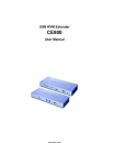
1
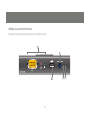
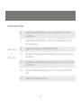
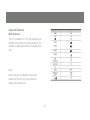
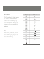
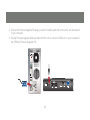
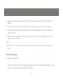
Installation Guide
KVM Extender with on board audio
GCE800W6
1
Part No. M0577
Overview
The GCE800 USB KVM Extender with on board audio allows access to a computer system from a remote
console (USB keyboard, mouse, monitor, stereo speakers, and microphone). It is perfect for factory and
construction sites, or any type of installation where the console needs to be in a conveniently accessible
location, but you want the system equipment to reside in a safe place - away from dust, dirt, and harsh
environmental influences. The GCE800 also is useful for control and security purposes. Store the system
unit in a secure area at the same time that you put the console in a location that offers convenient access.
Recognizing the increased importance of sound in the computing environment, the GCE800 improves
on earlier models by incorporating audio capability. Now, audio (stereo microphone and stereo speakers)
transmission can be extended to the remote system along with the KVM data.
The GCE800 USB KVM Extender improves on previous designs by using compact Cat 5 cable - the kind
commonly used in Ethernet networks which makes for a much neater, more convenient, more reliable data
transfer connection. In addition, the GCE800 has a built-in USB port that complies with the USB Mass
Storage specification and supports USB Mass Storage compliant flash drives. Setup is as easy as can be:
simply connect the computer system and local console components to the local GCE800 module, run
the Cat 5 cable to the Remote GCE800 module (up to 820 ft) ; and connect the console to the Remote
Module.
Note: Y
. ou can control numerous remote systems from a single console by combining the GCE800 with a
KVM switch.
3
Table of Contents
Overview
3
Keyboard Emulation
40
Package Contents
5
The Firmware Upgrade Utility
42
Features
6
Administrator Password
49
System Requirements
7
Appendix
50
Hardware Introduction
11
Specifications
55
Hardware Setup
15
Troubleshooting
59
Installation
17
User Notice
60
Operation
19
61
LED Display
22
Federal Communications Commission
(FCC) Statement CE Statement
OSD Operation
25
Limited Warranty
63
Contact
64
OSD Navigation
27
Hotkey Operation
33
4
Package Contents
The CE800 Audio KVM Extender package contains:
• 1 CE800L KVM Extender (Local Unit)
• 1 CE800R KVM Extender (Remote Unit)
• 1 Custom KVM 6 ft (1.8 m) Cable
• 2 Power Adapters
• 1 Firmware Upgrade Cable
• 1 Rack Mount Kit
• 1 User Manual
• 1 Quick Start Guide
Check to make sure that all the components are present and that nothing was damaged in shipping. If
you encounter a problem, contact your dealer.
Read this manual thoroughly and follow the installation and operation procedures carefully to prevent
any damage to the unit, and/or any of the devices connected to it.
5
Features
• Uses Cat 5 ( or better) to connect the Local and Remote Units – up to820 ft (250 meters) apart
• Control your system from either the local or remote consoles
• Pushbutton selection can lock control to either computer
• Built-in USB ports on both units support USB mass storage devices for simple file transfer
• Configurable security requires user name and password to mount USB storage devices
• Supports VGA, SVGA, and multi-sync monitors
• The local unit supports DDC, DDC2, and DDC2B monitors
• High Resolution Video – up to 1600 x 1200 @ 60 Hz
• Built-in 8KV ESD protection and 2KV surge protection
• Manually adjustable gain control for distance compensation.
• Supports microphone and powered stereo speakers
• Supports most two button scroll wheel mice
• Up gradable firmware
6
System Requirements
Consoles ( 1 each per console )
• A VGA, SVGA, or Multi-sync monitor capable of the highest resolution you want to use
• A USB style keyboard
• A USB style mouse
• A Microphone and Stereo Speakers (optional)
Note: If you connect a DDC type monitor to the Local unit, the monitor that connects to the Remote unit must be
able to support the highest video resolution that the DDC monitor can provide
Computers
•A VGA, SVGA or Multi-sync card
• A USB Host Controller and Type A USB Port
• Audio out (optional )
KVM
•VGA / SVGA support
• A USB Host Controller and Type A USB Port
• Hot key or OSD ( On Screen Display) switching
• Audio Support (optional)
7
Operating Systems
•
Windows 2000 and higher
•
Redhat 7.1, 7.2, 7.3, 8.0 and higher
•
Mandrake 9.0 and higher
•
SUSE 8.2 and higher
•
FreeBSD 4.2, 4.3, 4.5 and higher
•
Netware 6.0 and higher
Cables
For optimum signal integrity and to simplify the layout, we strongly recommend that you use the high-quality Custom USB KVM Cable that is provided with this package.
Cat 5 cable is the minimum required to connect the local and remote CE800 units. Cable of a lower standard may
result in degraded video signals. For best performance, we strongly recommend at least Cat 5 cable.
8
CE800L (Local Unit) Front View
Supported operating systems are shown in the table, below:
1
2
3
9
4
5
No.
Component
Description
1
KVM Port Section
This section is made up of a microphone jack, speaker
jack and KVM (keyboard, video, mouse), data connector.
The cable that links the CE800L to your local KVM
console plugs in here. Only KVM cables designed to work with this switch can be
used.
2
Audio connections
microphone and speakers connect here
3
USB Port
External USB Mass Storage compliant flash drives plug
into this port..
4
Operating Mode
Selection Switch
Pressing this switch toggles the operating mode between
Auto and Local. See Mode Selection, page 11 for details
5
Remote LED
6
Local LED
The Local Unit has two LEDs to indicate the operating
status of the Local and Remote units (see LED Display,
page 12 for details).
10
Safety Instructions
GCE800R (Remote Unit) Front View
2
1
Picture Compensation
LINK
3
11
4
5
6
No.
Component
Description
1
USB Peripheral Port
External USB Mass Storage compliant flash drives plug into this port.
2
Picture Compensation
Switches
These switches adjust the picture quality of the remote console. See Picture
Compensation, page 12 for details.
3
Picture Compensation
LED
Flashes to indicate that picture quality has been
adjusted. See Picture Compensation, page 12 for details.
4
Operating Mode
Selection Switch
Pressing this switch toggles the operating mode between Auto and Remote.
See Mode Selection, page 11 for details.
5
Remote LED
The Remote LED indicates the operating status of the Remote unit (see
CE800R (Remote Unit):, page 13, for details).
6
Link LED
Lights to indicate that the CE800R is connected to the CE800L
12
GCE800L / GCE800R Rear View
2
1
4
5
13
3
6
No.
Component
Description
1
Power Jack
The cable from the DC Power Adapter plugs into this jack.t
2
Keyboard and Mouse Ports
The console USB keyboards and mice plug into these ports. The ports are
color coded and marked with an icon to identify themselves.
3
Link Port
The Cat 5 cable that connects plugs into this connector.
4
Firmware Upgrade Port
(CE800L only
The Firmware Upgrade Cable that transfers the firmware upgrade data from
the administrator’s computer to the CE800L plugs in here.
5
Console Audio Jacks
The stereo microphone and stereo speakers plug into these connectors. The
ports are color coded and marked with an icon to identify themselves.
6
Video Port
The console monitors plug into these ports.
14
Hardware Setup
Before You Begin
Conventions
This manual uses the following conventions:
Monospaced Indicates text that you should key in.
[]
Indicates keys you should press. For example, [Enter] means to
press the Enter key. If keys need to be chorded, they appear
together in the same bracket with a plus sign between them:
[Ctrl+Alt].
1. Numbered lists represent procedures with sequential steps.
Bullet lists provide information, but do not involve sequential steps.
Indicates selecting the option (on a menu or dialog box, for example), that comes next. For example, Start
Run means to open the Start menu, then
select Run means to Start menu, and then select Run.
Indicates critical information.
15
Safety
1. Important safety information regarding the placement of this device is provided on page 51. Please review it before proceeding.
2. Make sure that power to all the devices you will be connecting up have been turned off. You must
unplug the power cords of any computers that have the Keyboard Power On function.
16
Installation
Setting up the USB KVM Extender System is simply a matter of plugging in the cables. Refer to the
diagram on the next page as you perform the following steps
1. Plug the cables from the local console devices (mouse, keyboard, monitor, microphone and speakers)
into their ports on the rear panel of the Local Unit (CE800L). The connectors are color coded and
marked with an icon for identification.
2. Connect the custom KVM cable provided to the KVM port on the CE800L’s front panel.
3. Connect the other end of the KVM cable into the appropriate ports on the computer system (or
Console section of the KVM switch). The connectors are color coded and marked with icons for
identification.
4. Connect one end of an ethernet cable to the Link port on the CE800L; then connect the other end to
the Link port on the CE800R.
Note: Ethernet cable is not supplied with this package. It requires a separate purchase. The cable length
can be up to 250 m (820’).
17
5. Connect the cables from the remote console devices to their ports on the rear panel of the remote unit
(CE800R).
6. Connect one of the power adapters (provided) to an AC source; connect the adapter’s power cable to
the Power Jack on the CE800L.
7. Connect the other power adapter (provided)to an AC source; connect the adapter’s power cable to the
Power Jack on the CE800R.
4
CE-800L
1
6
CE-800L
2
CE-800R
7
3
5
18
Operation
Basic Operation
Operating Modes
The CE800 USB KVM Extender utilizes three operating modes: Auto, Local, and Remote, as described in
the table below:
Mode
Description
Local
Only the local console has complete access.*
Remote
Only the remote console has complete access.*
Auto
Neither console has keyboard and mouse input control. The first console to
initiate key board or mouse command assumes control. Following this, if there
is no input for five seconds, the CE800 reverts to Auto Mode.
19
Mode Selection
The Operating Mode Selection Switch, located on each unit’s front panel, controls the operating mode of
the CE800 USB KVM Extender system.
Pressing the switch toggles the operating mode as follows:
Switch
Action
Local (CE800L) Selection
Switch
Only the local console has keyboard and mouse control the computer
Remote (CE800R) Selection
Switch
Only the remote console has keyboard and mouse control the computer
20
When the system is in Local Mode, the Remote unit’s selection switch is inactive. Pressing it has no
effect – the Remote operator cannot take over control. The Remote selection switch only becomes
active after the Local selection switch is pressed to return the system to Auto Mode.
Likewise, if the system is in Remote Mode, the Local unit’s selection switch is inactive – the Local
operator cannot take over control. The Local selection switch only becomes active after the Remote
selection switch is pressed to return the system to Auto Mode.
Picture Compensation
The quality of the video display can deteriorate with distance. The Picture Compensation switches
adjust the picture quality of the remote console.
If it becomes necessary to adjust the video signal, press the plus button (+) to increase the video
signal gain; press the minus button (-) to decrease the video signal gain. The Picture Compensation
LED blinks until compensation has completed, at which time it remains illuminated.
21
LED Display
The GCE800 Local and Remote Units have front panel LEDs to indicate their operating status, as shown
in the table below:
GCE800L (Local Unit):
LED
Local
Remote
Status
Indication
Off
Local Mode is in effect. The Local console has keyboard and mouse input control.
Flashing
Remote Mode is in effect. The Remote console has keyboard and mouse input control.
On
Auto Mode is in effect. The first console to establish keyboard or mouse input takes
control.
Off
Remote Mode is in effect. The Remote console has keyboard and mouse input control.
Flashing
Local Mode is in effect. The Local console has keyboard and mouse input control.
Auto Mode is in effect. The first console to establish keyboard or mouse input takes
control.
22
GCE800R (Remote Unit):
LED
Status
Indication
Remote
On
Remote Mode is in effect. The Remote console has input control.
Off
Local Mode is in effect. The Local console has input control.
Flashing
Auto Mode is in effect. The first console to initiate a command
assumes control
On
The CE800R is connected to the CE800L.
Off
The CE800R is not connected to the CE800L.
Flashing
A picture compensation button has been pushed (+ or –) and the CE800 is adjusting the gain.
Steady
Gain adjustment has been completed and saved.
Link
Compensation
23
USB Mass Storage
Both the CE800L and the CE800R have a built-in USB port that complies with the USB Mass Storage
specification and supports USB Mass Storage compliant flash drives.
When you connect a USB Mass Storage complaint flash drive into either unit’s USB port, it appears as a
removable drive on the computer.
As a security measure, if a flash drive is connected to the Remote unit, the OSD login screen appears (see
OSD operation no the next page). The operator must log in with a valid username and password before
continuing.
24
OSD Operation
Overview
The CE800 USB KVM Extender provides a convenient menu driven On Screen Display (OSD) to handle its
configuration parameters. All procedures start from the OSD Main Screen. To access the Main Screen:
1. Tap the OSD Hotkey (Scroll Lock) twice.
Note: [Scroll Lock] is the default OSD hotkey. You can change the hotkey to the Ctrl key (see OSD
HOTKEY, page 35, and see Alternate OSD Activation Keys, page 36).
The login dialog box appears:
25
2. Key in a valid username and password, then press [Enter].
Note: If this is the first time that the OSD is being run, or if the password function has not been set,
simply press [Enter]. The OSD Main Screen comes up in Administrator Mode. In this mode, you have
Administrator privileges, which provides access to the configuration parameters
Administrator Main Screen
After you log in to the OSD, if you are the
administrator, a screen similar to the one
below appears:
Note: If you are an ordinary user,
see User Configuration, page 32
26
OSD Navigation
The following principles govern the way you navigate through the OSD:
To dismiss the menu, and deactivate the OSD, Click the X at the upper right corner of the OSD Window;
or press [Esc].
To move up or down through the list one line at a time, Click the Up and Down Triangle symbols
use the Up and Down Arrow Keys on your keyboard.
or
To select a menu item click it or move the highlight bar to it with the arrow keys, then press [Enter].
If a submenu appears, make your choice either by double clicking it, or moving the highlight bar to it, then
pressing [Enter]. An icon of a pointing finger indicates the currently selected choice.
27
Administrator Configuration
The administer configuration settings are listed below:
Setting
Function
This function is used to set Usernames and Passwords
for the Administrator and Users:
1. One Administrator and four User passwords can be set.
SET USERNAME AND
PASSWORD
2. After you select the Administrator field or one of the User fields, a screen that allows
you to key in your username and password appears. The username and password
may be up to 12 characters long, and can consist of any combination of letters and
numbers.
3. For each individual, key in the Username and Password, then press [Enter]. To
modify or delete a previous Username and/or Password, use the backspace key to
erase individual letters or numbers.
OSD HOTKEY
Selects which Hotkey activates the OSD function:
[Scroll Lock] [Scroll Lock] or [Ctrl] [Ctrl].
28
Setting
HOTKEY COMMAND MODE
Function
Enables / Disables the Hotkey Command function. If the hotkey combinations conflict with
programs running on the computers, you may want to disable hotkey operation by turning
Hotkey Command Mode Off. The default is On
Selects which combination activates Hotkey Setting
HOTKEY
Mode (HSM): [Num Lock] + [–] or [Ctrl] + [F12]
The default is [Num Lock] + [–]
USER
If this setting is On, users have to provide a Username
AUTHENTICATION
and Password when they plug a flash drive into the USB port of the Remote unit. The
default is On.
29
Setting
Function
RESTORE DEFAULT VALUES
Selecting Y (Yes) undoes all changes and returns the CE800’s setup to the original factory
SET OPERATING
This function specifies the operating platform of the computer attached to the CE800L.
Choices are Win, Mac, Sun, and SPC*. The default is Win
SYSTEM
SET KEYBOARD
LANGUAGE
default settings.1
Selects the keyboard layout used by the computer connected to the CE800. Choices are
Auto, English,French, German, and Japanese.
Auto automatically detects the keyboard layout set for the computer and sets the CE800
accordingly. The default is Auto.
1You must be logged on as Administrator to restore factory defaults. To reset a forgotten Administrator password
see page 50
* SPC stands for Special Case. For certain operating systems (such as FSBD),
you may need to choose this option if you run into startup problems.
30
User Configuration
The CE800 USB KVM Extender supports up to four user accounts in addition to the administrator. When users
invoke the OSD, they get an OSD Main screen allows them to modify some of the configuration settings made by
the administrator.
The User OSD Main Screen looks similar to the one, below:
31
The configuration settings that users are allowed to make are explained in the table below:
Setting
CHANGE
PASSWORD
HOTKEY
COMMAND MODE
Function
Users can use this function to change the password that was assigned to them by the
administrator.
These settings are the same as the ones
described under Administrator Configuration, page 29.
HOTKEY
SET OPERATING
SYSTEM
32
Hotkey Operation
In addition to the OSD, the administrator and users can also use hotkey combinations to configure a
number of the CE800 USB KVM Extender’s working environment parameters.
Invoking Hotkey Mode
All Hotkey operations begin by invoking Hotkey Mode (HKM). To invoke
Hotkey Mode, do the following:
1. Hold down the Num Lock key
2. Press and release the minus key
3. Release the Num Lock key
[Num Lock] + [-]
Note: There is an alternative key combination to invoke HKM (see Alternate
Hotkey Invocation Keys, page 35).
33
When Hotkey Mode is active:
• The Caps Lock, and Scroll Lock LEDs flash in succession to indicate so. They stop flashing and
revert to normal status when you exit HKM.
• A Command Line appears on the monitor screen. The command line prompt is the word Hotkey:
in yellow text on a blue background. Hotkey information that you key in displays on the command
line.
• Ordinary keyboard and mouse functions are suspended – only Hotkey compliant keystrokes and
mouse clicks (described in the sections that follow), can be input.
• At the conclusion of some hotkey operations, you automatically exit hotkey mode. With some
operations, you must exit manually. To exit HKM manually, press [Esc] or [Spacebar].
Alternate Hotkey Invocation Keys
An alternate set of hotkey invocation keys is provided in case the default set conflicts with programs
running on the computers.
34
To switch to the alternate hotkey invocation set, do the following:
1. Invoke HKM (see page 19)
2. Press and release the H key
The hotkey invocation keys become the Ctrl key (instead of Num Lock) and the F12 key (instead of
Minus).
Note: This procedure is a toggle between the two methods. To revert back to the original [Num Lock]
[Minus] method, invoke HKM, then press and release the H key again.
Alternate OSD Activation Keys
The OSD activation method can be changed from tapping the Scroll Lock key twice to tapping the Ctrl
key twice ([Ctrl] [Ctrl]). To change the OSD
activation method, do the following:
1. Invoke HKM (see page 19)
2. Press and release the T key
35
Note:
1. This procedure is a toggle between the two methods. To revert back to the original [Scroll Lock] [Scroll
Lock] method, invoke HKM, then press and release the T key again.
2. For Mac systems we recommend using [Ctrl] [Ctrl] as the OSD activation keys since Scroll Lock is
used to emulate F14 in PC to Mac keyboard emulation (see Keyboard Emulation, page 23).
Enable / Disable Hotkeys
In case a conflict occurs with programs running on the computer, you may wish to disable the hotkey
function. To disable the hotkey function do the following:
1. Invoke HKM (see page 19)
2. Press and release the X key
Note: This procedure is a toggle between enabling / disabling the hotkey function. To revert back to the
original enabled status, invoke HKM, then press and release the X key again.
36
Keyboard Operating Platform
The CE800’s default configuration is for a PC Compatible keyboard operating platform. If you have a Mac
or a Sun on your installation, you can change the keyboard operating platform as follows:
3. Invoke HKM (see page 19)
4. Press and release the appropriate Function key (see table).
Key
[F1]
Operation
Sets the PC Compatible keyboard operating platform for the port
that currently has the KVM focus
[F2]
Sets the Mac keyboard operating platform for the port that currently
has the KVM focus.
[F3]
Sets the Sun keyboard operating platform for the port that currently
has the KVM focus.
37
Note:
1. The brackets indicate the keys you should press. Simply press the indicated keys - do not type the brackets.
2. After completing a setting, you automatically exit HKM.
USB Reset
Sometimes the USB keyboard and mouse connection to the CE800 needs to be reset. Instead of
unplugging and re-plugging them, a hotkey combination can perform the reset, as follows:
1. Invoke HKM (see page 19)
2. Press and release the F5 function key.
38
Hotkey Summary Table
[Num Lock] + [–]
or
[H]
Toggles between the default ([Num Lock] [–]) and alternate ([Ctrl] [F12]) Hotkey
invocation keys.
[T]
Toggles between the default ([Scroll Lock] [Scroll Lock]) and alternate ([Ctrl] [Ctrl])
OSD invocation keys.
[X]
Toggles between Enabling / Disabling the hotkey function.
[F1]
Sets the PC Compatible keyboard operating platform for the port that currently has
the KVM focus.
[F2]
Sets the Mac Compatible keyboard operating platform for the port that currently has
the KVM focus.
[F3]
Sets the Sun keyboard operating platform for the port that currently has the KVM
focus.
[F5]
Resets the USB keyboard and mouse.
[Ctrl] + [F12]
39
Keyboard Emulation
Mac Keyboard
The PC compatible (101/104 key) keyboard can
emulate the functions of the Mac keyboard. The
emulation mappings are listed in the table to the
right
Note:
When using key combinations, press and
release the first key (Ctrl), then press and
release the activation key.
40
Sun Keyboard
The PC compatible (101/104 key) keyboard
can emulate the functions of the Sun
keyboard when the Control key [Ctrl] is
used in conjunction with other keys. The
corresponding functions are shown in the
table below.
Note:
When using key combinations, press and
release the first key (Ctrl), then press and
release the activation key
41
The Firmware Upgrade Utility
The Windows-based Firmware Upgrade Utility (FWUpgrade.exe) provides a smooth, automated process
for upgrading the Extender’s firmware. The Utility comes as part of a Firmware Upgrade Package. New
firmware upgrade packages will be posted on our web site as they become available. Check the web site
regularly to find the latest packages and information relating to them: http://www.aten.com
To prepare for the firmware upgrade, do the following:
1. Unplug the power adapters from both units, and disconnect the KVM cable (to the local computer) from the CE800L’s front panel.
2. Go to our Internet support site and choose the model name that relates to your device (CE800) to get a list of available Firmware Upgrade Packages.
42
3. Choose the Firmware Upgrade Package you want to install (usually the most recent), and download it to your computer.
4. Use the Firmware Upgrade Cable provided with this unit to connect a COM port on your computer to the CE800L’s Firmware Upgrade Port
43
5. Make sure both units are connected by the Cat 5 cable, then plug in the Remote unit’s power
adapter.
6. Press and hold the Local unit’s Selection button, then plug in the Local unit’s power adapter.
7. Wait until both green front panel LEDs on the Local unit are flashing on and off, then release the
Selection button.
8. Make sure the orange LED on the front panel of the Remote unit is on (indicating that Firmware
Upgrade Mode is in effect.
Note:
If the LED is not on, or it is blinking, the unit is not ready to be upgraded. You must repeat steps 6
and 7.
Starting the Upgrade
To upgrade your firmware:
1. Run the downloaded Firmware Upgrade Package file - either by double clicking the file icon, or by
opening a command line and entering the full path to it.
44
The Firmware Upgrade Utility Welcome screen
appears:
Note: The screens shown in this section are for
reference only. The wording and layout of the
actual screens put up by the Firmware Upgrade
Utility may vary slightly from these examples.
2. Read and Agree to the License Agreement
(enable the I Agree radio button).
45
3. Click Next to continue. The Firmware Up grade Utility main screen appears:
The Utility inspects your installation. All the
devices capable of being upgraded by the
package are listed in the Device List panel.
4. As you select a device in the list, its descrip tion appears in the Device Description panel.
46
5. After you have made your device
selection(s),Click Next to perform the
upgrade.
If you enabled Check Firmware Version, the
Utility compares the device’s firmware level
with that of the upgrade files. If it finds that the
device’s version is higher than the upgrade
version, it brings up a dialog box informing you
of the situation and gives you the option to
Continue or Cancel.
47
Upgrade Succeeded
After the upgrade has completed, a screen
appears to inform you that the procedure was
successful:
Click Finish to close the Firmware Upgrade
Utility.
After successfully upgrading the firmware, the
switches automatically exit Firmware Upgrade
Mode.
Upgrade Failed
If the Upgrade Succeeded screen does not
appear, then the upgrade failed to complete
successfully. You should repeat the upgrade
procedure from the beginning.
48
Administrator Password
If you are unable to perform an administrator login can clear the login information from the local unit with
the following procedure:
1. Power off the unit by disconnecting the power cord and the CAT5 cable
2. Remove the cover.
3. Using a jumper cap, short the jumper labeled J7 on the mainboard
4. Reconnect the power cord wait 3 secs.
5. Power off the unit again
6. Remove the jumper cap from the jumper
7. Replace the cover on the device.
8. Reconnect power and the unit will be reset to Factory defaults including all passwords
49
Appendix
General Safety
Read all of these instructions. Save them for future reference.
Follow all warnings and instructions marked on the device.
• Do not place the device on any unstable surface (cart, stand, table, etc.). If the device falls, serious damage may result.
• Do not use the device near water.
• Do not place the device near, or over, radiators or heat registers.
• The device should never be placed in a built in enclosure unless adequate ventilation has been pro
vided.
• Never spill liquid of any kind on the device.
• Unplug the device from the wall outlet before cleaning. Do not use liquid or aerosol cleaners. Use a damp cloth for cleaning.
The device should be operated from the type of power source indicated on the marking label. If you are
not sure of the type of power available, consult your dealer or local power company
50
• Do not allow anything to rest on the power cord or cables.
• Route the power cord and cables so that they cannot be stepped on or tripped over.
• If an extension cord is used with this device make sure that the total of the ampere ratings of all prod
ucts used on this cord does not exceed the extension cord ampere rating.
• Make sure that the total of all products plugged into the wall outlet does not exceed 15 amperes.
• To help protect your system from sudden, transient increases and decreases in electrical power, use a surge suppressor, line conditioner, or un-interruptible power supply
• When connecting or disconnecting power to hot-pluggable power supplies, observe the following guidelines:
Install the power supply before connecting the power cable to the power supply.
Unplug the power cable before removing the power supply. If the system has multiple sources of power, disconnect power from the system by unplugging all power cables from the power supplies.
• Never push objects of any kind into or through cabinet slots. They may touch dangerous voltage points or short out parts resulting in a risk of fire or electrical shock.
• Do not attempt to service the device yourself. Refer all servicing to qualified service personnel.
51
• If the following conditions occur, unplug the device from the wall outlet and bring it to qualified service personnel for repair.
The power cord or plug has become damaged or frayed.
Liquid has been spilled into the device.
The device has been exposed to rain or water.
The device has been dropped, or the cabinet has been damaged.
The device exhibits a distinct change in performance, indicating a need for service.
The device does not operate normally when the operating instructions are followed.
• Only adjust those controls that are covered in the operating instructions.
Improper adjustment of other controls may result in damage that will require extensive work by a qualified
technician to repair
52
Rack Mounting
• Before working on the rack, make sure that the stabilizers are secured to the rack, extend to the floor, and that the full weight of the rack rests on the floor. Install front and side stabilizers on a single rack or front stabilizers for joined multiple racks
• Always load the rack from the bottom up, and load the heaviest items first.
• Make sure that the rack is level and stable before extending a device.
• Do not overload the AC supply branch circuit that provides power to the rack. The total rack load
should not exceed 80 percent of the branch circuit rating.
• Ensure that proper airflow is provided to devices in the rack.
• Do not step on or stand on any device when servicing other devices in a rack
1. Using the screws provided with the Rack Mount Kit, screw the mounting bracket into the top or bot
tom of the unit as shown in the diagram below.
2. Screw the bracket into any convenient location on the rack.
Note: These screws are not provided. We recommend that you use M5 x 12 Phillips Type I, recessed type
screws.
53
Phillips hex head
M3 X 8
54
Specifications
CE800L
Function
Computer Con
nections
1
Console
Connectors
KVM Port
CE800R
N/A
KB
1 x USB Type A Female (White)
Video
1 x HDB - 15 Female (Blue)
Mouse
1 x USB Type A Female (White)
Speaker
1x Mini Stereo Jack (Green)
Microphone
1x Mini Stereo Jack (Pink)
Keyboard
1 x SPHD-15 Female (Yellow)
N/A
Video
Mouse
1x Mini Stereo Jack (Green)
Speaker
1x Mini Stereo Jack (Pink)
Microphone
N/A
N/A
55
CE800L
Function
Computer Connections
Switches
LEDs
CE800R
F/W Upgrade
1x 4-conductor 3.5 mm jack
Power
1 x DC Jack (Black)
Unit to Unit (Link)
1 x RJ-45 (Black)
Access Select
1 x Pushbutton
Picture Compensation
N/A
2 x Pushbutton
Local
1 (Green)
N/A
Remote
1 (Green)
1 (Green)
Link
N/A
1 (Green)
Compensation
N/A
Power Compensation
1 (Orange)
DC 5,0V; 6,0 W
VIdeo
1600 X 1200 @ 60hz, 150 m
1024 X 768 @ 60hz, 250 m
56
CE800L
Function
Environment
0-50o C
Storage Temp.
-20-50o
Humidity
Physical
CE800R
Operating Temp.
0-80% RH
Housing
Metal
Properties
Weight
.50 kg
Dimension (L x W x H)
49 kg
20.00 x 8.00 x 2.50 cm
57
Twisted Pair pin assignments
Twisted Pair wiring diagram
PAIR 3
PAIR 2
1
2
PAIR 1
3
4
W-O O W-G BI
5
Pin
Assignment
1
/V OUT B
2
V OUT B
3
/V OUT G
4
V OUT R
5
V OUT R
6
V OUT G
8
7
/DO
Br
8
DO
PAIR 4
6
7
W-BI G W-Br
JACK POSITIONS
T568B
AT&T 258A
58
Troubleshooting
Problem
Action
No video
Make sure that all cables are securely plugged into their sockets.
Poor video quality
The video quality can be improved by reducing the refresh rate.
59
User Notice
All information, documentation, and specifications contained in this manual are subject to change without prior
notification by the manufacturer. The manufacturer makes no representations or warranties, either expressed
or implied, with respect to the contents hereof and specifically disclaims any warranties as to merchantability or
fitness for any particular purpose. Any of the manufacturer’s software described in this manual is sold or licensed
`as is’.
Should the programs prove defective following their purchase, the buyer (and not the manufacturer, its distributor,
or its dealer), assumes the entire cost of all necessary servicing, repair and any incidental or consequential
damages resulting from any defect in the software.
The manufacturer of this system is not responsible for any radio and/or TV interference caused by unauthorized
modifications to this device. It is the
responsibility of the user to correct such interference.
The manufacturer is not responsible for any damage incurred in the operation of this system if the correct
operational voltage setting was not selected prior to operation. PLEASE VERIFY THAT THE VOLTAGE SETTING IS
CORRECT BEFORE USE.
60
Federal Communications Commission (FCC) Statement
15.21
You are cautioned that changes or modifications not expressly approved by the part responsible for
compliance could void the user’s authority to operate the equipment.
15.105(b)
his equipment has been tested and found to comply with the limits for a Class B digital device, pursuant
to part 15 of the FCC rules. These limits are designed to provide reasonable protection against harmful
interference in a residential installation. This equipment generates, uses and can radiate radio frequency
energy and, if not installed and used in accordance with the instructions, may cause harmful interference
to radio communications. However, there is no guarantee that interference will not occur in a particular
installation. If this equipment does cause harmful interference to radio or television reception, which can
be determined by turning the equipment off and on, the user is encouraged to try to correct the
interference by one or more of the following measures:
- Reorient or relocate the receiving antenna.
- Increase the separation between the equipment and receiver.
- Connect the equipment into an outlet on a circuit different from that to which the receiver is con
nected.
- Consult the dealer or an experienced radio/TV technician for help.
61
THIS DEVICE COMPLIES WITH PART 15 OF THE FCC RULES. OPERATION IS SUBJECT TO THE
FOLLOWING TWO CONDITIONS:
1. this device may not cause interference and
2. this device must accept any interference, including interference that may cause undesired operation
of the device.
FCC RF Radiation Exposure Statement:
This equipment complies with FCC radiation exposure limits set forth for an uncontrolled environment.
End users must follow the specific c operating instructions for satisfying RF exposure compliance. This
transmitter must not be co-located or operating in conjunction with any other antenna or transmitter.
CE Statement
This device has been tested and found to comply with the requirements set up in the council directive on
the approximation of the law of member states relating to EMC Directive 89/336/EEC, Low Voltage
Directive 73/23/EEC and R&TTE Directive 99/5/EC.
62
Limited Warranty
IN NO EVENT SHALL THE DIRECT VENDOR’S LIABILITY FOR DIRECT, INDIRECT, SPECIAL, INCIDENTAL OR CONSEQUENTIAL DAMAGES RESULTING FROM THE USE OF THE PRODUCT, DISK, OR ITS
DOCUMENTATION EXCEED THE PRICE PAID FOR THE PRODUCT.
The direct vendor makes no warranty or representation, expressed, implied, or statutory with respect to
the contents or use of this documentation, and especially disclaims its quality, performance, merchantability,
or fitness for any particular purpose.
The direct vendor also reserves the right to revise or update the device or documentation without obligation to notify any individual or entity of such revisions, or updates. For further inquiries please contact your
direct vendor.
63
Contact
IOGEAR, INC.
23 Hubble
Irvine, CA 92618
P 949.453.8782
F 949.453.8785
Visit us at: www.iogear.com
© 2007 IOGEAR. All Rights reserved. Part No. M0510
IOGEAR, the IOGEAR logo, are trademarks or registered trademarks of IOGEAR, Inc. Microsoft and Windows are registered trademarks of
Microsoft Corporation. All other brand and product names are trademarks or registered trademarks of their respective holders. IOGEAR makes
no warranty of any kind with regards to the information presented in this document. All information furnished here is for informational purposes
only and is subject to change without notice. IOGEAR, Inc. assumes no responsibility for any inaccuracies or errors that may appear in this
document.
64
About Us
FUN
IOGEAR offers connectivity solutions that are innovative, fun, and stylish,
helping people enjoy daily life using our high technology products.
GREEN
IOGEAR is an environmentally conscious company that emphasizes the
importance of conserving natural resources. The use of our technology
solutions helps reduce electronic waste.
HEALTH
IOGEAR supports healthy and fit lifestyles. By integrating products with the
latest scientific developments, IOGEAR’s solutions enhance the life of endusers.
© 2007 IOGEAR, INC.